WO2020004125A1 - 冷凍サイクル及び温水ヒートポンプ - Google Patents
冷凍サイクル及び温水ヒートポンプ Download PDFInfo
- Publication number
- WO2020004125A1 WO2020004125A1 PCT/JP2019/024009 JP2019024009W WO2020004125A1 WO 2020004125 A1 WO2020004125 A1 WO 2020004125A1 JP 2019024009 W JP2019024009 W JP 2019024009W WO 2020004125 A1 WO2020004125 A1 WO 2020004125A1
- Authority
- WO
- WIPO (PCT)
- Prior art keywords
- refrigerant
- mass
- refrigeration cycle
- cop
- less
- Prior art date
- Legal status (The legal status is an assumption and is not a legal conclusion. Google has not performed a legal analysis and makes no representation as to the accuracy of the status listed.)
- Ceased
Links
Images

Classifications
-
- F—MECHANICAL ENGINEERING; LIGHTING; HEATING; WEAPONS; BLASTING
- F25—REFRIGERATION OR COOLING; COMBINED HEATING AND REFRIGERATION SYSTEMS; HEAT PUMP SYSTEMS; MANUFACTURE OR STORAGE OF ICE; LIQUEFACTION SOLIDIFICATION OF GASES
- F25B—REFRIGERATION MACHINES, PLANTS OR SYSTEMS; COMBINED HEATING AND REFRIGERATION SYSTEMS; HEAT PUMP SYSTEMS
- F25B1/00—Compression machines, plants or systems with non-reversible cycle
-
- F—MECHANICAL ENGINEERING; LIGHTING; HEATING; WEAPONS; BLASTING
- F25—REFRIGERATION OR COOLING; COMBINED HEATING AND REFRIGERATION SYSTEMS; HEAT PUMP SYSTEMS; MANUFACTURE OR STORAGE OF ICE; LIQUEFACTION SOLIDIFICATION OF GASES
- F25B—REFRIGERATION MACHINES, PLANTS OR SYSTEMS; COMBINED HEATING AND REFRIGERATION SYSTEMS; HEAT PUMP SYSTEMS
- F25B39/00—Evaporators; Condensers
- F25B39/04—Condensers
Definitions
- the present invention relates to a refrigeration cycle and a hot water heat pump.
- Patent Literature 1 describes an air conditioner that uses a mixed refrigerant of R1234yf and R134a or a mixed refrigerant of R32 and R1234yf because there is no single refrigerant that can replace the R410A device.
- the global warming potential (GWP) of R1234yf is as small as “4”, but the global warming potential (GWP) of R32 is as large as “675”. Further, when only R32 is replaced with a refrigerant having a low global warming potential (GWP), a target energy consumption efficiency (COP) may not be obtained.
- the present invention has been made in view of the above circumstances, and provides a refrigeration cycle and a hot water heat pump that can improve the energy consumption efficiency as compared with a single refrigerant while reducing the global warming potential of a mixed refrigerant. Is what you do.
- a refrigeration cycle circulates a refrigerant through a refrigerant circuit in which a compressor, an evaporator, a decompression device, and a condenser are connected by refrigerant piping, and the evaporator causes a heat source fluid and the refrigerant And a heat exchange between the refrigerant and the refrigerant to be heated by the condenser, wherein the refrigerant is a mixed refrigerant of R1234ze (E) and R1233zd (E).
- the global warming potential (GWP) of R1234ze (E) alone is “1”, and the global warming potential (GWP) of R1233zd (E) alone is “1”. Can be reduced. Further, by using a refrigerant mixture of R1234ze (E) and R1233zd (E), it is possible to improve energy consumption efficiency (COP) as compared with a single refrigerant of R1233zd (E).
- a temperature difference between an inlet temperature and an outlet temperature of the heat source fluid is 7 ° C or more
- the R1234ze (E) is used as a first refrigerant.
- the mixing ratio of the first refrigerant in the mixed refrigerant may be more than 0% by mass and 75% by mass or less.
- a mixing ratio of the first refrigerant in the mixed refrigerant may be 20% by mass or more and 60% by mass or less.
- a mixing ratio of the first refrigerant in the mixed refrigerant may be 30% by mass or more and 50% by mass or less.
- a mixing ratio of the first refrigerant in the mixed refrigerant may be 35% by mass or more and 45% by mass or less.
- the temperature difference between the inlet temperature and the outlet temperature of the fluid to be heated is 7 ° C. or more while suppressing the global warming potential (GWP) of the mixed refrigerant from increasing.
- GWP global warming potential
- COP energy consumption efficiency
- a temperature difference between an inlet temperature and an outlet temperature of the heat source fluid is 5 ° C or more and less than 7 ° C.
- a mixing ratio of the first refrigerant in the mixed refrigerant may be more than 0% by mass and 70% by mass or less.
- a mixing ratio of the first refrigerant in the mixed refrigerant may be not less than 20% by mass and not more than 40% by mass.
- the temperature difference between the inlet temperature and the outlet temperature of the fluid to be heated is 5 ° C. while suppressing the global warming potential (GWP) of the mixed refrigerant from increasing.
- GWP global warming potential
- the energy consumption efficiency (COP) can be improved.
- a temperature difference between an inlet temperature and an outlet temperature of the heat source fluid is 2 ° C or more and less than 5 ° C
- the R1234ze (E ) As the first refrigerant and R1233zd (E) as the second refrigerant, the mixing ratio of the first refrigerant in the mixed refrigerant may be greater than 0% by mass and 40% by mass or less.
- the temperature difference between the inlet temperature and the outlet temperature of the fluid to be heated is 2 ° C. or more, while suppressing the global warming potential (GWP) of the mixed refrigerant from increasing.
- the energy consumption efficiency (COP) can be improved.
- a hot water heat pump includes the refrigeration cycle according to any one of the first to eighth aspects, wherein the fluid to be heated is water.
- the effect of improving the energy consumption efficiency (COP) by the mixed refrigerant can be obtained, and the environmental load can be reduced, so that the commerciality of the hot water heat pump can be improved.
- COP energy consumption efficiency
- the energy consumption efficiency can be improved as compared with the single refrigerant while reducing the global warming potential of the mixed refrigerant.
- the vertical axis is a graph in which the energy consumption efficiency (COP) is plotted, and the horizontal axis is the mass ratio (%) of the first refrigerant in the refrigerant, showing a case where the temperature difference between the inlet and outlet of the heat source water is 7 ° C. or more.
- the vertical axis is a graph in which the energy consumption efficiency (COP) is plotted, and the horizontal axis is the mass ratio (%) of the first refrigerant in the refrigerant, in which the difference between the inlet and outlet temperature of the heat source water is 5 ° C.
- the vertical axis is a graph in which the energy consumption efficiency (COP) is plotted, and the horizontal axis is the mass ratio (%) of the first refrigerant in the refrigerant, where the temperature difference between the inlet and the outlet of the heat source water is 2 ° C. It is a graph in which the vertical axis represents the temperature slip (° C.) and the horizontal axis represents the mass ratio (%) of the first refrigerant.
- COP energy consumption efficiency
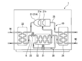
- FIG. 1 is a configuration diagram illustrating a schematic configuration of a hot water heat pump according to an embodiment of the present invention.
- the hot water heat pump 1 of the present embodiment includes a refrigeration cycle 10 configured by circulating a refrigerant R through a refrigerant circuit.
- the refrigerant circuit of the refrigeration cycle 10 is configured by connecting a compressor 21, an evaporator 22, a main expansion valve (decompression device) 23, and a condenser 24 by a refrigerant pipe 25.
- a so-called economizer cycle 30 is further combined with a refrigerant circuit.
- the economizer cycle 30 illustrated in this embodiment connects a turbo compressor 21A having two-stage impellers 21a and 21b as a compressor 21, a sub-expansion valve 31, and an intercooler 32 by a refrigerant pipe 25. It is configured.
- the refrigerant circuit combined with the economizer cycle 30 adiabatically expands a part of the refrigerant R from the condenser 24 by the sub-expansion valve 31, cools the remaining part of the refrigerant R from the condenser 24, and increases the refrigerating effect. ing.
- the refrigerant R evaporated in the intercooler 32 of the economizer cycle 30 is drawn into the second stage impeller 21b.
- the refrigerant R evaporated by the intercooler 32 has a lower temperature than the refrigerant R flowing from the first-stage impeller 21a to the second-stage impeller 21b. Therefore, in the economizer cycle 30, it is possible to increase the filling efficiency and improve the energy consumption efficiency (COP; Coefficient Of ⁇ Performance).
- the hot water heat pump 1 exchanges heat between the heat source water W1 and the refrigerant R in the evaporator 22, and exchanges heat in the condenser 24 between water to be heated (hereinafter simply referred to as hot water W2) and the refrigerant R.
- the inlet temperature of the heat source water W1 exemplified in this embodiment is 10 to 50 ° C.
- the outlet temperature of the hot water W2 is 90 ° C. at the maximum.
- the refrigeration cycle 10 is a so-called Lorentz cycle in which the refrigerant temperature changes (in other words, temperature slips) when the phase of the refrigerant R changes.
- the refrigerant R flowing through the refrigerant circuit of the refrigeration cycle 10 is a mixed refrigerant (also referred to as a mixed composition refrigerant) in which different types of first refrigerant and second refrigerant are mixed.
- the refrigerant R in this embodiment is a mixture of R1234ze (E) as the first refrigerant and R1233zd (E) as the second refrigerant.
- R1234ze (E) is simply referred to as “first refrigerant”
- R1233zd (E) is simply referred to as “second refrigerant”.
- At least one of the evaporator 22 and the condenser 24 exemplified in this embodiment has a heat source of a type capable of defining the flow directions of the heat source water W1, the hot water W2, and the refrigerant R, which are fluids, in one direction.
- An exchanger may be used. Examples of such a heat exchanger include a plate heat exchanger, a plate fin heat exchanger, and a microchannel heat exchanger.
- the mixing ratio (in other words, the mass ratio) of the first refrigerant in the refrigerant R is, for example, a temperature difference between the inlet temperature and the outlet temperature of the heat source water W1 of the hot water heat pump 1 described above (hereinafter, simply referred to as an inlet / outlet temperature difference). Is 7 ° C. or more, the content is more than 0% by mass and 75% by mass or less.
- the mixing ratio of the first refrigerant in the refrigerant R may be 20% by mass or more and 60% by mass or less.
- the mixing ratio of the first refrigerant in the refrigerant R may be 30% by mass or more and 50% by mass or less.
- the mixing ratio of the first refrigerant in the refrigerant R may be 35% by mass or more and 45% by mass or less.
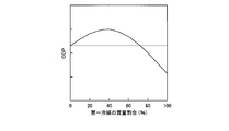
- FIG. 2 is a graph in which the vertical axis represents energy consumption efficiency (COP) and the horizontal axis represents the mass ratio (%) of the first refrigerant in the refrigerant, and shows a case where the difference between the inlet and outlet temperatures of the heat source water is 7 ° C. or more. I have.
- COP energy consumption efficiency
- FIG. 2 when the first refrigerant is 0% by mass, it is a single refrigerant of the second refrigerant, and when the first refrigerant is 100% by mass, it is a single refrigerant of the first refrigerant. (Hereinafter the same applies to FIGS. 3 and 4).
- the energy consumption efficiency (COP) of a single refrigerant composed of only the second refrigerant is simply referred to as “reference COP”.
- the energy consumption efficiency (COP) of the single refrigerant composed of only the first refrigerant is smaller than the energy consumption efficiency (COP) of the single refrigerant composed of only the second refrigerant.
- the mass ratio of the first refrigerant to the second refrigerant (in other words, the mixing ratio) is from 0% by mass to 100% by mass. %
- the energy consumption efficiency (COP) of the refrigerant R changes in a curved shape protruding upward. More specifically, the energy consumption efficiency (COP) of the refrigerant R changes in a curve shape that peaks (maximum) when the mass ratio of the first refrigerant is around 40% by mass.
- the energy consumption efficiency (COP) shown in FIG. 2 is larger than the reference COP when the mass ratio of the first refrigerant is greater than 0% by mass and 75% by mass or less.
- the energy consumption efficiency (COP) of the mixed refrigerant gradually decreases from near the peak of 40% by mass to 100% by mass.
- the energy consumption efficiency (COP) of the mixed refrigerant in the region where the mass ratio of the first refrigerant is greater than 75% by mass (more specifically, in the region greater than 75% by mass and 100% by mass or less). ) Is lower than the reference COP.
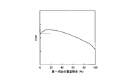
- FIG. 3 is a graph in which the vertical axis represents the energy consumption efficiency (COP) and the horizontal axis represents the mass ratio (%) of the first refrigerant in the refrigerant, and shows a case where the temperature difference between the inlet and the outlet of the heat source water is 5 ° C. .
- the refrigerant R The energy consumption efficiency (COP) changes in a curved shape protruding upward. More specifically, the energy consumption efficiency (COP) of the refrigerant R changes in a curve shape having a peak (maximum) when the mass ratio of the first refrigerant in the refrigerant R is around 30% by mass.
- the energy consumption efficiency (COP) shown in FIG. 3 is larger than the reference COP in a range where the mass ratio of the first refrigerant in the refrigerant R is more than 0% by mass and 70% by mass or less.
- the energy consumption efficiency (COP) of the refrigerant R gradually decreases from a peak of around 30% by mass to 100% by mass. In other words, in a region where the mass ratio of the first refrigerant in the refrigerant R is larger than 70% by mass (more specifically, in a region larger than 70% by mass and 100% by mass or less), the energy consumption of the refrigerant R is reduced.
- the efficiency (COP) is lower than the reference COP.
- FIG. 4 is a graph in which the vertical axis represents energy consumption efficiency (COP) and the horizontal axis represents the mass ratio (%) of the first refrigerant in the refrigerant, and shows a case where the difference between the inlet and outlet temperatures of the heat source water is 2 ° C. .
- COP energy consumption efficiency
- FIG. 4 when the temperature difference between the inlet and the outlet of the heat source water W1 of the hot water heat pump 1 is 2 ° C., when the mass ratio of the first refrigerant to the second refrigerant is increased from 0% by mass to 100% by mass, the refrigerant R
- the energy consumption efficiency (COP) changes in a curved shape protruding upward. More specifically, the energy consumption efficiency (COP) of the refrigerant R changes in a curve shape that peaks (maximum) when the mass ratio of the first refrigerant is around 10% by mass.
- the energy consumption efficiency (COP) shown in FIG. 4 is larger than the reference COP in a range where the mass ratio of the first refrigerant in the refrigerant R is more than 0% by mass and 40% by mass or less.
- the energy consumption efficiency (COP) of the refrigerant R gradually decreases from around 10% by mass at the peak to 100% by mass. In other words, in a region where the mass ratio of the first refrigerant in the refrigerant R is larger than 40% by mass (more specifically, in a region larger than 40% by mass and 100% by mass or less), the energy consumption of the refrigerant R is reduced.
- the efficiency (COP) is lower than the reference COP.
- the mass ratio of the first refrigerant in the refrigerant R is as described above.
- the maximum temperature slip occurs at 40 to 50% by mass, and the energy consumption efficiency (COP) becomes maximum.
- the peak of the energy consumption efficiency (COP) does not change when the temperature difference between the entrance and the exit is 7 ° C. or more.
- the peak position of the energy consumption efficiency (COP) is located on the left side of the above graph as the entrance / exit temperature difference is smaller. Furthermore, when the entrance / exit temperature difference is smaller than 7 ° C., the peak value of the energy consumption efficiency (COP) is smaller as the entrance / exit temperature difference is smaller.
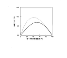
- FIG. 5 is a graph in which the vertical axis represents the temperature slip (° C.) and the horizontal axis represents the mass ratio (%) of the first refrigerant.
- the solid line indicates the temperature slip of the refrigerant R in the evaporator 22 when the internal pressure (absolute pressure) is 0.35 MPaA.
- the broken line indicates the temperature slip of the refrigerant R in the condenser 24 when the internal pressure (absolute pressure) is 1.8 MPaA.
- the temperature slip of the refrigerant R in the evaporator 22 becomes the maximum value of 7 ° C. when the mass ratio of the first refrigerant is 50% by mass, and the temperature slip of the refrigerant R in the condenser 24 is:
- the maximum value is 9.5 ° C. when the mass ratio of the first refrigerant is 40%.
- the energy consumption efficiency (COP) due to temperature slip is maximized by setting the mass ratio of the first refrigerant in the refrigerant R to about 40% by mass. it can.
- the temperature difference between the inlet and the outlet of the raw heat water W1 shown in FIG. 3 is 5 ° C.
- the mass ratio of the first refrigerant in the refrigerant R is set to about 30% by mass
- the energy consumption efficiency (COP) due to temperature slip is maximized.
- the mass ratio of the first refrigerant in the refrigerant R is set to about 10% by mass, the energy consumption efficiency (COP) due to temperature slip can be reduced. Can be maximized. That is, in a region where the difference between the inlet and outlet temperatures of the heat source water W1 is smaller than the maximum temperature slip of the refrigerant R, the smaller the difference between the inlet and outlet temperatures of the heat source water W1 is, the lower the mass ratio of the first refrigerant in the refrigerant R is. (COP) can be maximized.
- the global warming potential (GWP) of the first refrigerant alone is “1”
- the global warming potential (GWP) of the second refrigerant alone is “1”. . Therefore, according to the above embodiment, the global warming potential (GWP) of the refrigerant R can be reduced. Furthermore, by using a mixed refrigerant of the first refrigerant and the second refrigerant as the refrigerant R, it is possible to improve energy consumption efficiency (COP) as compared with a single refrigerant of the second refrigerant.
- COP energy consumption efficiency
- the difference between the inlet and outlet temperatures of the heat source water W1 is 7 ° C. or more, and the mass ratio of the first refrigerant in the refrigerant R1 is more than 0% by mass and 75% by mass or less. Therefore, according to the above embodiment, the energy consumption efficiency (COP) is higher than that of the second refrigerant alone having a higher energy consumption efficiency (COP) than the energy consumption efficiency (COP) of the first refrigerant alone. Can be obtained.
- the mass ratio of the first refrigerant in the refrigerant R is smaller than 20% by mass or larger than 60% by mass.
- Higher energy consumption efficiency (COP) can be obtained.
- the mass ratio of the first refrigerant in the refrigerant R is smaller than 30% by mass or larger than 50% by mass.
- Higher energy consumption efficiency (COP) can be obtained.
- the mass ratio of the first refrigerant in the refrigerant R is smaller than 35% by mass or larger than 45% by mass.
- Higher energy consumption efficiency (COP) can be obtained.
- the mass ratio of the first refrigerant in the refrigerant R is larger than 0% by mass and 70% by mass. % Or less. Therefore, when the temperature difference between the inlet and the outlet of the heat source water W1 is 5 ° C. or more and less than 7 ° C., a higher global warming potential (GWP) of the refrigerant R is suppressed and a higher energy consumption efficiency (COP) is obtained. be able to.
- GWP global warming potential
- COP energy consumption efficiency
- the mass ratio of the first refrigerant in the refrigerant R is set to 20% by mass or more and 40% by mass or less.
- Higher energy consumption efficiency (COP) can be obtained than when the mass ratio of the first refrigerant is smaller than 20% by mass or larger than 40% by mass.
- the mass ratio of the first refrigerant in the refrigerant R is larger than 0% by mass and 40% by mass. % Or less. Therefore, when the temperature difference between the inlet and the outlet of the heat source water W1 is 2 ° C. or more and less than 5 ° C., a higher energy consumption efficiency (COP) is obtained while suppressing an increase in the global warming potential (GWP) of the mixed refrigerant. be able to.
- COP energy consumption efficiency
- the hot water W2 is heated by the refrigeration cycle 10 having the above-described configuration. Accordingly, the effect of improving the energy consumption efficiency (COP) by the refrigerant R can be obtained, and the environmental load can be reduced, so that the commercial value of the hot water heat pump 1 can be improved.
- COP energy consumption efficiency
- the present invention is not limited to the configuration of the embodiment described above, and the design can be changed without departing from the gist of the present invention.
- the refrigeration cycle 10 includes the economizer cycle 30 has been described.
- the refrigeration cycle 10 is not limited to the one having the economizer cycle 30.
- the case where the heat source water W1 is used as the heat source fluid has been described as an example, but a fluid other than water may be used as the heat source.
- the refrigeration cycle 10 is used for the hot water heat pump 1
- the refrigeration cycle 10 may be used for a cooling / heating device other than the hot water heat pump.
- the energy consumption efficiency can be improved as compared with the single refrigerant while reducing the global warming potential of the mixed refrigerant.
Landscapes
- Engineering & Computer Science (AREA)
- Physics & Mathematics (AREA)
- Mechanical Engineering (AREA)
- Thermal Sciences (AREA)
- General Engineering & Computer Science (AREA)
- Heat-Pump Type And Storage Water Heaters (AREA)
Abstract
冷凍サイクルは、圧縮機、蒸発器、減圧装置及び凝縮器を冷媒配管で接続した冷媒回路に冷媒を流通させて、前記蒸発器によって熱源流体と前記冷媒とを熱交換し、前記凝縮器によって加熱対象となる加熱対象流体と前記冷媒とを熱交換する。前記冷媒は、R1234ze(E)とR1233zd(E)との混合冷媒である。
Description
この発明は、冷凍サイクル及び温水ヒートポンプに関する。
本願は、2018年6月27日に日本に出願された特願2018-121860号について優先権を主張し、その内容をここに援用する。
本願は、2018年6月27日に日本に出願された特願2018-121860号について優先権を主張し、その内容をここに援用する。
冷凍サイクルを備える冷熱機器においては、熱を輸送する媒質としてフロン系の冷媒を用いる場合が多い。このような冷媒は、オゾン破壊係数(ODP;Ozone Depletion Potential)や地球温暖化係数(GWP;Global Warming Potential)が小さいことが望まれる。しかし、単一種類の冷媒を用いると、所望のエネルギー消費効率(COP;Coefficient Of Performance)が得られない場合があった。
特許文献1には、単一冷媒でR410A機器の置き換えとなり得るものが存在しないため、R1234yfとR134aとの混合冷媒や、R32とR1234yfとの混合冷媒を用いる空気調和機が記載されている。
特許文献1には、単一冷媒でR410A機器の置き換えとなり得るものが存在しないため、R1234yfとR134aとの混合冷媒や、R32とR1234yfとの混合冷媒を用いる空気調和機が記載されている。
しかしながら、特許文献1の混合冷媒において、R1234yfの地球温暖化係数(GWP)は「4」と小さいが、R32の地球温暖化係数(GWP)は「675」と大きい。
また、R32のみを地球温暖化係数(GWP)の低い冷媒に置き換えた場合に、目標とするエネルギー消費効率(COP;Coefficient Of Performance)を得られない可能性がある。
この発明は、上記事情に鑑みてなされたものであり、混合冷媒の地球温暖化係数を低減しつつ、単一冷媒の場合よりもエネルギー消費効率を向上することができる冷凍サイクル及び温水ヒートポンプを提供するものである。
また、R32のみを地球温暖化係数(GWP)の低い冷媒に置き換えた場合に、目標とするエネルギー消費効率(COP;Coefficient Of Performance)を得られない可能性がある。
この発明は、上記事情に鑑みてなされたものであり、混合冷媒の地球温暖化係数を低減しつつ、単一冷媒の場合よりもエネルギー消費効率を向上することができる冷凍サイクル及び温水ヒートポンプを提供するものである。
上記の課題を解決するために以下の構成を採用する。
この発明の第一態様によれば、冷凍サイクルは、圧縮機、蒸発器、減圧装置及び凝縮器を冷媒配管で接続した冷媒回路に冷媒を流通させて、前記蒸発器によって熱源流体と前記冷媒とを熱交換し、前記凝縮器によって加熱対象となる加熱対象流体と前記冷媒とを熱交換する冷凍サイクルであって、前記冷媒は、R1234ze(E)とR1233zd(E)との混合冷媒である。
R1234ze(E)単体の地球温暖化係数(GWP)は、「1」であり、R1233zd(E)単体の地球温暖化係数(GWP)は「1」であるため、混合冷媒の地球温暖化係数を低減できる。
さらに、R1234ze(E)とR1233zd(E)との混合冷媒を用いることで、R1233zd(E)の単一冷媒よりもエネルギー消費効率(COP)を向上することが可能となる。
この発明の第一態様によれば、冷凍サイクルは、圧縮機、蒸発器、減圧装置及び凝縮器を冷媒配管で接続した冷媒回路に冷媒を流通させて、前記蒸発器によって熱源流体と前記冷媒とを熱交換し、前記凝縮器によって加熱対象となる加熱対象流体と前記冷媒とを熱交換する冷凍サイクルであって、前記冷媒は、R1234ze(E)とR1233zd(E)との混合冷媒である。
R1234ze(E)単体の地球温暖化係数(GWP)は、「1」であり、R1233zd(E)単体の地球温暖化係数(GWP)は「1」であるため、混合冷媒の地球温暖化係数を低減できる。
さらに、R1234ze(E)とR1233zd(E)との混合冷媒を用いることで、R1233zd(E)の単一冷媒よりもエネルギー消費効率(COP)を向上することが可能となる。
この発明の第二態様によれば、第一態様に係る冷凍サイクルにおいて、前記熱源流体の入口温度と出口温度との温度差は、7℃以上であり、前記R1234ze(E)を第一冷媒とし、前記R1233zd(E)を第二冷媒とした場合、前記混合冷媒における前記第一冷媒の混合割合は、0質量%よりも大きく75質量%以下であってもよい。
この発明の第三態様によれば、第二態様に係る冷凍サイクルにおいて、前記混合冷媒における前記第一冷媒の混合割合は、20質量%以上、かつ、60質量%以下であってもよい。
この発明の第四態様によれば、第二態様に係る冷凍サイクルにおいて、前記混合冷媒における前記第一冷媒の混合割合は、30質量%以上、かつ、50質量%以下であってもよい。
この発明の第五態様によれば、第二態様に係る冷凍サイクルにおいて、前記混合冷媒における前記第一冷媒の混合割合は、35質量%以上、かつ、45質量%以下であってもよい。
第二から第五態様のように構成することで、混合冷媒の地球温暖化係数(GWP)が大きくなることを抑制しつつ、加熱対象流体の入口温度と出口温度との温度差が7℃以上の場合に、エネルギー消費効率(COP)の向上を図ることが可能となる。
第二から第五態様のように構成することで、混合冷媒の地球温暖化係数(GWP)が大きくなることを抑制しつつ、加熱対象流体の入口温度と出口温度との温度差が7℃以上の場合に、エネルギー消費効率(COP)の向上を図ることが可能となる。
この発明の第六態様によれば、第一態様に係る冷凍サイクルにおいて、前記熱源流体の入口温度と出口温度との温度差は、5℃以上、かつ7℃未満、前記R1234ze(E)を第一冷媒とし、前記R1233zd(E)を第二冷媒とした場合、前記混合冷媒における前記第一冷媒の混合割合は、0質量%よりも大きく70質量%以下であってもよい。
この発明の第七態様によれば、第六態様に係る冷凍サイクルにおいて、前記混合冷媒における前記第一冷媒の混合割合は、20質量%以上、かつ、40質量%以下であってもよい。
第六態様や第七態様のように構成することで、混合冷媒の地球温暖化係数(GWP)が大きくなることを抑制しつつ、加熱対象流体の入口温度と出口温度との温度差が5℃以上、かつ、7℃未満の場合に、エネルギー消費効率(COP)の向上を図ることができる。
第六態様や第七態様のように構成することで、混合冷媒の地球温暖化係数(GWP)が大きくなることを抑制しつつ、加熱対象流体の入口温度と出口温度との温度差が5℃以上、かつ、7℃未満の場合に、エネルギー消費効率(COP)の向上を図ることができる。
この発明の第八態様によれば、第一態様に係る冷凍サイクルにおいて、前記熱源流体の入口温度と出口温度との温度差は、2℃以上、かつ、5℃未満であり、前記R1234ze(E)を第一冷媒とし、前記R1233zd(E)を第二冷媒とした場合、前記混合冷媒における前記第一冷媒の混合割合は、0質量%よりも大きく40質量%以下であってもよい。
第八態様のように構成することで、混合冷媒の地球温暖化係数(GWP)が大きくなることを抑制しつつ、加熱対象流体の入口温度と出口温度との温度差が2℃以上、かつ、5℃未満の場合に、エネルギー消費効率(COP)の向上を図ることができる。
第八態様のように構成することで、混合冷媒の地球温暖化係数(GWP)が大きくなることを抑制しつつ、加熱対象流体の入口温度と出口温度との温度差が2℃以上、かつ、5℃未満の場合に、エネルギー消費効率(COP)の向上を図ることができる。
この発明の第九態様によれば、温水ヒートポンプは、第一から八態様の何れか一つの態様に係る冷凍サイクルを備え、前記加熱対象流体は水である。
このように構成することで、混合冷媒によるエネルギー消費効率(COP)の向上効果が得られるとともに、環境負荷を低くできるため、温水ヒートポンプの商品性を向上できる。
このように構成することで、混合冷媒によるエネルギー消費効率(COP)の向上効果が得られるとともに、環境負荷を低くできるため、温水ヒートポンプの商品性を向上できる。
上記冷凍サイクル及び温水ヒートポンプによれば、混合冷媒の地球温暖化係数を低減しつつ、単一冷媒の場合よりもエネルギー消費効率を向上することができる。
次に、この発明の実施形態における冷凍サイクル及び温水ヒートポンプを図面に基づき説明する。
図1は、この発明の実施形態における温水ヒートポンプの概略構成を示す構成図である。
図1に示すように、この実施形態の温水ヒートポンプ1は、冷媒回路に冷媒Rを流通させることで構成される冷凍サイクル10を備えている。この冷凍サイクル10の冷媒回路は、圧縮機21、蒸発器22、主膨張弁(減圧装置)23、及び凝縮器24を冷媒配管25で接続して構成されている。この実施形態における冷凍サイクル10は、更に、冷媒回路に、いわゆるエコノマイザサイクル30が組み合わされている。
図1は、この発明の実施形態における温水ヒートポンプの概略構成を示す構成図である。
図1に示すように、この実施形態の温水ヒートポンプ1は、冷媒回路に冷媒Rを流通させることで構成される冷凍サイクル10を備えている。この冷凍サイクル10の冷媒回路は、圧縮機21、蒸発器22、主膨張弁(減圧装置)23、及び凝縮器24を冷媒配管25で接続して構成されている。この実施形態における冷凍サイクル10は、更に、冷媒回路に、いわゆるエコノマイザサイクル30が組み合わされている。
この実施形態で例示するエコノマイザサイクル30は、圧縮機21として二段の羽根車21a,21bを有するターボ圧縮機21Aと、副膨張弁31と、中間冷却器32と、を冷媒配管25で接続して構成されている。このエコノマイザサイクル30を組み合わせた冷媒回路は、凝縮器24からの冷媒Rの一部を副膨張弁31によって断熱膨張させて、凝縮器24からの冷媒Rの残部を冷却して冷凍効果を増加させている。
エコノマイザサイクル30の中間冷却器32で蒸発した冷媒Rは、二段目の羽根車21bに吸引される。この中間冷却器32で蒸発した冷媒Rは、一段目の羽根車21aから二段目の羽根車21bに流入する冷媒Rの温度よりも低温となる。そのため、エコノマイザサイクル30では、充填効率が上がりエネルギー消費効率(COP;Coefficient Of Performance)を向上することが可能となっている。
温水ヒートポンプ1は、熱源水W1と冷媒Rとを蒸発器22で熱交換し、加熱対象となる水(以下、単に温水W2と称する)と冷媒Rとを凝縮器24で熱交換する。この実施形態で例示する熱源水W1の入口温度は、10~50℃であり、温水W2の出口温度は、最高で90℃である。
冷凍サイクル10は、冷媒Rの相変化時に冷媒温度が変化(言い換えれば、温度すべり)する、いわゆるローレンツサイクルである。この冷凍サイクル10の冷媒回路を流れる冷媒Rは、それぞれ種類の異なる第一冷媒と第二冷媒とを混合した混合冷媒(混合組成冷媒ともいう)となっている。この実施形態における冷媒Rは、第一冷媒としてのR1234ze(E)と第二冷媒としてのR1233zd(E)とを混合してなる。以下の説明において、R1234ze(E)を単に「第一冷媒」と称し、R1233zd(E)を単に「第二冷媒」と称する。
この実施形態で例示する蒸発器22と凝縮器24との少なくとも一方は、流体である熱源水W1、温水W2、及び、冷媒Rの流れる方向を、それぞれ一方向に規定することができる形式の熱交換器を使用しても良い。このような熱交換器としては、プレート型熱交換器、プレートフィン型熱交換器、マイクロチャネル式熱交換器を例示できる。このような熱交換器を用いることで、蒸発器22や凝縮器24の内部における飽和温度の変化を流れ方向で順次変化させることができる。そして、冷媒Rと、熱源水W1や温水W2との流れを、いわゆるクロスフロー(対向流)とすることができる。そのため、冷媒Rの飽和温度の変化と熱源水W1や温水W2の温度変化を同一傾向とすることが可能となり、熱交換効率を向上させることができる。
冷媒Rにおける第一冷媒の混合割合(換言すれば、質量割合)は、例えば、上述した温水ヒートポンプ1の熱源水W1の入口温度と出口温度との温度差(以下、単に出入口温度差と称する)が7℃以上の場合、0質量%よりも大きく75質量%以下とされている。
さらに、上述した温水ヒートポンプ1の熱源水W1の出入口温度差が7℃以上の場合、冷媒Rにおける第一冷媒の混合割合は、20質量%以上、かつ、60質量%以下としてもよい。
さらに、上述した温水ヒートポンプ1の熱源水W1の出入口温度差が7℃以上の場合、冷媒Rにおける第一冷媒の混合割合は、30質量%以上、かつ、50質量%以下としてもよい。
さらに、上述した温水ヒートポンプ1の熱源水W1の出入口温度差が7℃以上の場合、冷媒Rにおける第一冷媒の混合割合は、35質量%以上、かつ、45質量%以下としてもよい。
図2は、縦軸をエネルギー消費効率(COP)、横軸を冷媒における第一冷媒の質量割合(%)としたグラフであって、熱源水の出入口温度差が7℃以上の場合を示している。
図2において、第一冷媒が0質量%のときは、第二冷媒の単一冷媒であることを意味し、第一冷媒が100質量%のときは、第一冷媒の単一冷媒であることを意味している(以下、図3、図4も同様)。また、以下の説明においては、第二冷媒のみからなる単一冷媒のエネルギー消費効率(COP)を単に「基準COP」と称する。第一冷媒のみからなる単一冷媒のエネルギー消費効率(COP)は、第二冷媒のみからなる単一冷媒のエネルギー消費効率(COP)よりも小さい。
図2において、第一冷媒が0質量%のときは、第二冷媒の単一冷媒であることを意味し、第一冷媒が100質量%のときは、第一冷媒の単一冷媒であることを意味している(以下、図3、図4も同様)。また、以下の説明においては、第二冷媒のみからなる単一冷媒のエネルギー消費効率(COP)を単に「基準COP」と称する。第一冷媒のみからなる単一冷媒のエネルギー消費効率(COP)は、第二冷媒のみからなる単一冷媒のエネルギー消費効率(COP)よりも小さい。
図2に示すように、温水ヒートポンプ1の熱源水W1の出入口温度差が7℃以上の場合、第二冷媒に対する第一冷媒の質量割合(換言すれば、混合割合)を0質量%から100質量%まで増加させると、冷媒Rのエネルギー消費効率(COP)は、上方に向かって凸となる曲線状に変化する。より具体的には、冷媒Rのエネルギー消費効率(COP)は、第一冷媒の質量割合が40質量%付近でピーク(極大)となる曲線状に変化している。
図2に示すエネルギー消費効率(COP)は、第一冷媒の質量割合が0質量%よりも大きく75質量%以下の範囲で、基準COPよりも大きくなっている。その一方で、混合冷媒のエネルギー消費効率(COP)は、ピークとなる40質量%付近から100質量%まで、徐々に減少している。言い換えれば、第一冷媒の質量割合が75質量%よりも大きい領域(より具体的には、75質量%よりも大きく、かつ、100質量%以下の領域)において、混合冷媒のエネルギー消費効率(COP)は、基準COPよりも低くなっている。
図3は、縦軸をエネルギー消費効率(COP)、横軸を冷媒における第一冷媒の質量割合(%)としたグラフであって、熱源水の出入口温度差が5℃の場合を示している。
図3に示すように、温水ヒートポンプ1の熱源水W1の出入口温度差が5℃の場合、第二冷媒に対する第一冷媒の質量割合を0質量%から100質量%まで増加させると、冷媒Rのエネルギー消費効率(COP)は、上方に向かって凸となる曲線状に変化する。より具体的には、冷媒Rのエネルギー消費効率(COP)は、冷媒Rにおける第一冷媒の質量割合が30質量%付近でピーク(極大)となる曲線状に変化している。
図3に示すように、温水ヒートポンプ1の熱源水W1の出入口温度差が5℃の場合、第二冷媒に対する第一冷媒の質量割合を0質量%から100質量%まで増加させると、冷媒Rのエネルギー消費効率(COP)は、上方に向かって凸となる曲線状に変化する。より具体的には、冷媒Rのエネルギー消費効率(COP)は、冷媒Rにおける第一冷媒の質量割合が30質量%付近でピーク(極大)となる曲線状に変化している。
図3に示すエネルギー消費効率(COP)は、冷媒Rにおける第一冷媒の質量割合が0質量%よりも大きく70質量%以下の範囲で、基準COPよりも大きくなっている。その一方で、冷媒Rのエネルギー消費効率(COP)は、ピークとなる30質量%付近から100質量%まで、徐々に減少している。言い換えれば、冷媒Rにおける第一冷媒の質量割合が70質量%よりも大きい領域(より具体的には、70質量%よりも大きく、かつ、100質量%以下の領域)において、冷媒Rのエネルギー消費効率(COP)は、基準COPよりも低くなっている。
図4は、縦軸をエネルギー消費効率(COP)、横軸を冷媒における第一冷媒の質量割合(%)としたグラフであって、熱源水の出入口温度差が2℃の場合を示している。
図4に示すように、温水ヒートポンプ1の熱源水W1の出入口温度差が2℃の場合、第二冷媒に対する第一冷媒の質量割合を0質量%から100質量%まで増加させると、冷媒Rのエネルギー消費効率(COP)は、上方に向かって凸となる曲線状に変化する。より具体的には、冷媒Rのエネルギー消費効率(COP)は、第一冷媒の質量割合が10質量%付近でピーク(極大)となる曲線状に変化している。
図4に示すように、温水ヒートポンプ1の熱源水W1の出入口温度差が2℃の場合、第二冷媒に対する第一冷媒の質量割合を0質量%から100質量%まで増加させると、冷媒Rのエネルギー消費効率(COP)は、上方に向かって凸となる曲線状に変化する。より具体的には、冷媒Rのエネルギー消費効率(COP)は、第一冷媒の質量割合が10質量%付近でピーク(極大)となる曲線状に変化している。
図4に示すエネルギー消費効率(COP)は、冷媒Rにおける第一冷媒の質量割合が0質量%よりも大きく40質量%以下の範囲で、基準COPよりも大きくなっている。その一方で、冷媒Rのエネルギー消費効率(COP)は、ピークとなる10質量%付近から100質量%まで、徐々に減少している。言い換えれば、冷媒Rにおける第一冷媒の質量割合が40質量%よりも大きい領域(より具体的には、40質量%よりも大きく、かつ、100質量%以下の領域)において、冷媒Rのエネルギー消費効率(COP)は、基準COPよりも低くなっている。
上述した冷媒Rは、例えば、蒸発器22の内部圧力(絶対圧)が0.35MPaA、凝縮器24の内部圧力(絶対圧)が1.8MPaである場合、冷媒Rにおける第一冷媒の質量割合が40~50質量%で最大温度すべりが生じ、エネルギー消費効率(COP)が最大となる。そして、エネルギー消費効率(COP)のピークは、出入口温度差が7℃以上において変化しない。
その一方で、出入口温度差が7℃よりも小さい場合、エネルギー消費効率(COP)のピークの位置は、出入口温度差が小さいほど、上述したグラフの左側に位置する。さらに、出入口温度差が7℃よりも小さい場合、エネルギー消費効率(COP)のピーク値は、出入口温度差が小さいほど小さくなっている。
図5は、縦軸を温度すべり(℃)横軸を、第一冷媒の質量割合(%)としたグラフである。図5のグラフにおいて、実線は、内部圧力(絶対圧)が0.35MPaAのときの蒸発器22における冷媒Rの温度すべりを示している。破線は、内部圧力(絶対圧)が1.8MPaAのときの凝縮器24における冷媒Rの温度すべりを示している。
図5に示すように、蒸発器22における冷媒Rの温度すべりは、第一冷媒の質量割合が50質量%のときに最大値である7℃となり、凝縮器24における冷媒Rの温度すべりは、第一冷媒の質量割合が40%のときに最大値である9.5℃となっている。熱源水W1の出入口温度差が、蒸発器22と凝縮器24を合わせた温度すべりの値を上回ると、温度すべりによるエネルギー消費効率(COP)の向上がはかられる。
図2に示す熱原水W1の出入口温度差が7℃以上の場合には、冷媒Rにおける第一冷媒の質量割合を40質量%程度にすれば、温度すべりによるエネルギー消費効率(COP)を最大化できる。また、図3に示す熱原水W1の出入口温度差が5℃の場合には、冷媒Rにおける第一冷媒の質量割合を30質量%程度にすれば、温度すべりによるエネルギー消費効率(COP)を最大化できる。同様に、図4に示す熱原水W1の出入口温度差が2℃の場合には、冷媒Rにおける第一冷媒の質量割合を10質量%程度にすれば、温度すべりによるエネルギー消費効率(COP)を最大化できる。
つまり、冷媒Rの最大温度すべりよりも熱源水W1の出入口温度差が小さい領域では、熱源水W1の出入口温度差が小さいほど冷媒Rにおける第一冷媒の質量割合を低下させることで、エネルギー消費効率(COP)を最大化できる。
つまり、冷媒Rの最大温度すべりよりも熱源水W1の出入口温度差が小さい領域では、熱源水W1の出入口温度差が小さいほど冷媒Rにおける第一冷媒の質量割合を低下させることで、エネルギー消費効率(COP)を最大化できる。
上述した実施形態の冷凍サイクル10では、第一冷媒の単体の地球温暖化係数(GWP)は、「1」であり、第二冷媒の単体の地球温暖化係数(GWP)は「1」である。したがって、上記実施形態によれば、冷媒Rの地球温暖化係数(GWP)を低減できる。
さらに、第一冷媒と第二冷媒との混合冷媒を冷媒Rとして用いることで、第二冷媒の単一冷媒よりもエネルギー消費効率(COP)を向上することが可能となる。
さらに、第一冷媒と第二冷媒との混合冷媒を冷媒Rとして用いることで、第二冷媒の単一冷媒よりもエネルギー消費効率(COP)を向上することが可能となる。
上述した実施形態の冷凍サイクル10では、熱源水W1の出入口温度差は、7℃以上であり、冷媒R1における第一冷媒の質量割合は、0質量%よりも大きく75質量%以下である。したがって、上記実施形態によれば、第一冷媒の単体のエネルギー消費効率(COP)よりも高いエネルギー消費効率(COP)を有する第二冷媒の単体の場合よりも、更に高いエネルギー消費効率(COP)を得ることができる。
さらに、冷媒Rにおける第一冷媒の質量割合を20質量%以上、かつ、60質量%以下とすることで、第一冷媒の質量割合を20質量%よりも小さい場合や、60質量%よりも大きくする場合よりも、高いエネルギー消費効率(COP)を得ることができる。
さらに、冷媒Rにおける第一冷媒の質量割合を30質量%以上、かつ、50質量%以下とすることで、第一冷媒の質量割合を30質量%よりも小さい場合や、50質量%よりも大きくする場合よりも、高いエネルギー消費効率(COP)を得ることができる。
さらに、冷媒Rにおける第一冷媒の質量割合を35質量%以上、かつ、45質量%以下とすることで、第一冷媒の質量割合を35質量%よりも小さい場合や、45質量%よりも大きくする場合よりも、高いエネルギー消費効率(COP)を得ることができる。
上述した実施形態の冷凍サイクル10では、熱源水W1の出入口温度差が5℃以上、かつ、7℃未満の場合に、冷媒Rにおける第一冷媒の質量割合は、0質量%よりも大きく70質量%以下である。したがって、熱源水W1の出入口温度差が5℃以上で7℃未満の場合に、冷媒Rの地球温暖化係数(GWP)が大きくなることを抑制しつつ、より高いエネルギー消費効率(COP)を得ることができる。
さらに、熱源水W1の出入口温度差が5℃以上、かつ、7℃未満の場合に、冷媒Rにおける第一冷媒の質量割合は、20質量%以上、かつ、40質量%以下とすることで、第一冷媒の質量割合を20質量%よりも小さい場合や、40質量%よりも大きくする場合よりも、高いエネルギー消費効率(COP)を得ることができる。
上述した実施形態の冷凍サイクル10では、熱源水W1の出入口温度差が2℃以上、かつ、5℃未満の場合に、冷媒Rにおける第一冷媒の質量割合は、0質量%よりも大きく40質量%以下とした。したがって、熱源水W1の出入口温度差が2℃以上で5℃未満の場合に、混合冷媒の地球温暖化係数(GWP)が大きくなることを抑制しつつ、より高いエネルギー消費効率(COP)を得ることができる。
上述した実施形態の温水ヒートポンプ1では、上述した構成を備える冷凍サイクル10により温水W2を加熱している。したがって、冷媒Rによるエネルギー消費効率(COP)の向上効果が得られるとともに、環境負荷を低くできるため、温水ヒートポンプ1の商品性を向上できる。
この発明は上述した実施形態の構成に限られるものではなく、その要旨を逸脱しない範囲で設計変更可能である。
例えば、上述した実施形態では、冷凍サイクル10がエコノマイザサイクル30を有する場合について説明した。しかし、冷凍サイクル10は、エコノマイザサイクル30を有するものに限られない。
さらに、上述した実施形態では、熱源流体として熱源水W1を用いる場合を一例に説明したが、熱源として水以外の流体を用いても良い。
例えば、上述した実施形態では、冷凍サイクル10がエコノマイザサイクル30を有する場合について説明した。しかし、冷凍サイクル10は、エコノマイザサイクル30を有するものに限られない。
さらに、上述した実施形態では、熱源流体として熱源水W1を用いる場合を一例に説明したが、熱源として水以外の流体を用いても良い。
また、上述した実施形態では、冷凍サイクル10を温水ヒートポンプ1に用いる場合について説明したが、温水ヒートポンプ以外の冷熱機器に用いても良い。
上記冷凍サイクル及び温水ヒートポンプによれば、混合冷媒の地球温暖化係数を低減しつつ、単一冷媒の場合よりもエネルギー消費効率を向上することができる。
1 温水ヒートポンプ
10 冷凍サイクル
21 圧縮機
21a 羽根車
21A ターボ圧縮機
21b 羽根車
22 蒸発器
23 主膨張弁
24 凝縮器
25 冷媒配管
30 エコノマイザサイクル
31 副膨張弁
32 中間冷却器
W1 熱源水
W2 温水
R 冷媒
10 冷凍サイクル
21 圧縮機
21a 羽根車
21A ターボ圧縮機
21b 羽根車
22 蒸発器
23 主膨張弁
24 凝縮器
25 冷媒配管
30 エコノマイザサイクル
31 副膨張弁
32 中間冷却器
W1 熱源水
W2 温水
R 冷媒
Claims (9)
- 圧縮機、蒸発器、減圧装置及び凝縮器を冷媒配管で接続した冷媒回路に冷媒を流通させて、前記蒸発器によって熱源流体と前記冷媒とを熱交換し、前記凝縮器によって加熱対象となる加熱対象流体と前記冷媒とを熱交換する冷凍サイクルであって、
前記冷媒は、R1234ze(E)とR1233zd(E)との混合冷媒である冷凍サイクル。 - 前記熱源流体の入口温度と出口温度との温度差は、7℃以上であり、
前記R1234ze(E)を第一冷媒とし、前記R1233zd(E)を第二冷媒とした場合、前記混合冷媒における前記第一冷媒の混合割合は、0質量%よりも大きく75質量%以下である請求項1に記載の冷凍サイクル。 - 前記混合冷媒における前記第一冷媒の混合割合は、20質量%以上、かつ、60質量%以下である請求項2に記載の冷凍サイクル。
- 前記混合冷媒における前記第一冷媒の混合割合は、30質量%以上、かつ、50質量%以下である請求項2に記載の冷凍サイクル。
- 前記混合冷媒における前記第一冷媒の混合割合は、35質量%以上、かつ、45質量%以下である請求項2に記載の冷凍サイクル。
- 前記熱源流体の入口温度と出口温度との温度差は、5℃以上、かつ、7℃未満であり、
前記R1234ze(E)を第一冷媒とし、前記R1233zd(E)を第二冷媒とした場合、前記混合冷媒における前記第一冷媒の混合割合は、0質量%よりも大きく70質量%以下である請求項1に記載の冷凍サイクル。 - 前記混合冷媒における前記第一冷媒の混合割合は、20質量%以上、かつ、40質量%以下である請求項6に記載の冷凍サイクル。
- 前記熱源流体の入口温度と出口温度との温度差は、2℃以上、かつ、5℃未満であり、
前記R1234ze(E)を第一冷媒とし、前記R1233zd(E)を第二冷媒とした場合、前記混合冷媒における前記第一冷媒の混合割合は、0質量%よりも大きく40質量%以下である請求項1に記載の冷凍サイクル。 - 請求項1から8の何れか一項に記載の冷凍サイクルを備え、前記加熱対象流体は水である温水ヒートポンプ。
Applications Claiming Priority (2)
| Application Number | Priority Date | Filing Date | Title |
|---|---|---|---|
| JP2018-121860 | 2018-06-27 | ||
| JP2018121860A JP2020003124A (ja) | 2018-06-27 | 2018-06-27 | 冷凍サイクル及び温水ヒートポンプ |
Publications (1)
| Publication Number | Publication Date |
|---|---|
| WO2020004125A1 true WO2020004125A1 (ja) | 2020-01-02 |
Family
ID=68986542
Family Applications (1)
| Application Number | Title | Priority Date | Filing Date |
|---|---|---|---|
| PCT/JP2019/024009 Ceased WO2020004125A1 (ja) | 2018-06-27 | 2019-06-18 | 冷凍サイクル及び温水ヒートポンプ |
Country Status (2)
| Country | Link |
|---|---|
| JP (1) | JP2020003124A (ja) |
| WO (1) | WO2020004125A1 (ja) |
Cited By (1)
| Publication number | Priority date | Publication date | Assignee | Title |
|---|---|---|---|---|
| CN121252282A (zh) * | 2025-11-19 | 2026-01-02 | 湖南工程学院 | 基于低gwp混合工质的复叠式高温热泵系统及性能优化方法 |
Citations (3)
| Publication number | Priority date | Publication date | Assignee | Title |
|---|---|---|---|---|
| JPH05223383A (ja) * | 1991-07-04 | 1993-08-31 | Tokyo Gas Co Ltd | ヒートポンプ装置 |
| CN103937458A (zh) * | 2014-04-04 | 2014-07-23 | 西安交通大学 | 有机朗肯循环混合工质 |
| JP2014210913A (ja) * | 2013-03-14 | 2014-11-13 | ハネウェル・インターナショナル・インコーポレーテッド | 高温ヒートポンプ用途のための低gwp流体 |
Family Cites Families (1)
| Publication number | Priority date | Publication date | Assignee | Title |
|---|---|---|---|---|
| JP5990972B2 (ja) * | 2012-03-28 | 2016-09-14 | 株式会社富士通ゼネラル | 空気調和機 |
-
2018
- 2018-06-27 JP JP2018121860A patent/JP2020003124A/ja active Pending
-
2019
- 2019-06-18 WO PCT/JP2019/024009 patent/WO2020004125A1/ja not_active Ceased
Patent Citations (3)
| Publication number | Priority date | Publication date | Assignee | Title |
|---|---|---|---|---|
| JPH05223383A (ja) * | 1991-07-04 | 1993-08-31 | Tokyo Gas Co Ltd | ヒートポンプ装置 |
| JP2014210913A (ja) * | 2013-03-14 | 2014-11-13 | ハネウェル・インターナショナル・インコーポレーテッド | 高温ヒートポンプ用途のための低gwp流体 |
| CN103937458A (zh) * | 2014-04-04 | 2014-07-23 | 西安交通大学 | 有机朗肯循环混合工质 |
Cited By (1)
| Publication number | Priority date | Publication date | Assignee | Title |
|---|---|---|---|---|
| CN121252282A (zh) * | 2025-11-19 | 2026-01-02 | 湖南工程学院 | 基于低gwp混合工质的复叠式高温热泵系统及性能优化方法 |
Also Published As
| Publication number | Publication date |
|---|---|
| JP2020003124A (ja) | 2020-01-09 |
Similar Documents
| Publication | Publication Date | Title |
|---|---|---|
| JP6042026B2 (ja) | 冷凍サイクル装置 | |
| CN106030219B (zh) | 空气调节装置 | |
| US10443900B2 (en) | Heat pump | |
| CN102597658A (zh) | 热泵 | |
| CN107076467B (zh) | 空气调节装置 | |
| JP6188918B2 (ja) | 冷凍装置 | |
| JP2013148330A (ja) | ヒートポンプ | |
| WO2016059696A1 (ja) | 冷凍サイクル装置 | |
| CN107109198A (zh) | 热循环用工作介质 | |
| WO2019225237A1 (ja) | 輸送用冷凍装置 | |
| JP2009300001A (ja) | 冷凍サイクル装置 | |
| JP6223545B2 (ja) | 冷凍装置 | |
| WO2014199445A1 (ja) | 冷凍装置 | |
| JP2020003124A (ja) | 冷凍サイクル及び温水ヒートポンプ | |
| US6739143B1 (en) | Refrigerating device | |
| CN104697229B (zh) | 热泵机组 | |
| WO2018008129A1 (ja) | 冷凍サイクル装置 | |
| CN108700340B (zh) | 制冷循环装置 | |
| JPWO2016189810A1 (ja) | ヒートポンプ装置 | |
| JP6695034B2 (ja) | ヒートポンプ装置 | |
| WO2023095260A1 (ja) | 空気調和機 | |
| JP2010216778A (ja) | 冷凍サイクル装置 | |
| JP2010112618A (ja) | 空気調和装置 | |
| JPWO2017138052A1 (ja) | 冷凍サイクル装置 | |
| Hui | Greener refrigerants |
Legal Events
| Date | Code | Title | Description |
|---|---|---|---|
| 121 | Ep: the epo has been informed by wipo that ep was designated in this application |
Ref document number: 19824783 Country of ref document: EP Kind code of ref document: A1 |
|
| NENP | Non-entry into the national phase |
Ref country code: DE |
|
| 122 | Ep: pct application non-entry in european phase |
Ref document number: 19824783 Country of ref document: EP Kind code of ref document: A1 |