WO2020003893A1 - 光ファイバーの製造方法、及び、光ファイバー - Google Patents
光ファイバーの製造方法、及び、光ファイバー Download PDFInfo
- Publication number
- WO2020003893A1 WO2020003893A1 PCT/JP2019/021825 JP2019021825W WO2020003893A1 WO 2020003893 A1 WO2020003893 A1 WO 2020003893A1 JP 2019021825 W JP2019021825 W JP 2019021825W WO 2020003893 A1 WO2020003893 A1 WO 2020003893A1
- Authority
- WO
- WIPO (PCT)
- Prior art keywords
- refractive index
- core
- optical fiber
- light
- index modulation
- Prior art date
- Legal status (The legal status is an assumption and is not a legal conclusion. Google has not performed a legal analysis and makes no representation as to the accuracy of the status listed.)
- Ceased
Links
Images






Classifications
-
- G—PHYSICS
- G02—OPTICS
- G02B—OPTICAL ELEMENTS, SYSTEMS OR APPARATUS
- G02B6/00—Light guides; Structural details of arrangements comprising light guides and other optical elements, e.g. couplings
- G02B6/02—Optical fibres with cladding with or without a coating
Definitions
- the present invention relates to a method for manufacturing an optical fiber used for a laser oscillator.
- an optical fiber having a core that propagates light in a length direction a plurality of regions (referred to as refractive index modulation regions) having a refractive index higher (or lower) than the refractive index of the core are defined inside the core. Those formed at intervals are known.
- the plurality of refractive index modulation regions act as diffraction gratings for the light. Therefore, an optical fiber in which a plurality of refractive index modulation regions are formed as described above is referred to as “fiber Bragg grating (FBG)”.
- FBG fiber Bragg grating
- light having a wavelength determined by the refractive index of the optical fiber and the predetermined interval is extracted as reflected light.
- a plurality of refractive index modulation regions are formed at the above-mentioned predetermined intervals in the vicinity of both ends of an optical fiber in which a core is doped with a rare earth element, etc.
- light having a wavelength determined by the predetermined interval can be amplified by reciprocating in the optical fiber. That is, laser oscillation can be realized in the optical fiber.
- Patent Document 1 discloses a technique in which a core layer of an optical fiber is irradiated with pulsed laser light to cause a chemical reaction in the core layer, thereby forming a refractive index modulation region in the core layer.
- the optical fiber is moved by the grating period, and the core layer is irradiated with pulsed laser light again, so that a plurality of refractive index modulations are provided at intervals of the grating period. Forming an area.
- the pulse laser beam could not be sufficiently focused inside the core, only a weak reaction could occur inside the core, and a refractive index modulation region having a high reflectance could be formed. Did not. Therefore, in order to manufacture an optical fiber exhibiting sufficient performance as an oscillation medium of a laser oscillator, it was necessary to form a large number of refractive index modulation regions inside the core. Forming a large number of refractive index modulation regions inside the core means forming the refractive index modulation regions over a wide range in the length direction of the core.
- the characteristics of the refractive index modulation region (especially, the reflectance) differ in the length direction of the core due to fluctuations in the characteristics in the length direction of the core. It was difficult to obtain highly selective laser oscillation. Further, when forming a large number of refractive index modulation regions inside the core, it is necessary to repeatedly irradiate the inside of the core with a pulsed laser, so that it takes time to manufacture an optical fiber as an oscillation medium of a laser oscillator.
- the width of the refractive index modulation region formed in the core in the length direction was increased because the pulse laser beam could not be sufficiently focused in the core. Therefore, it is necessary to increase the distance between adjacent refractive index modulation regions so that adjacent refractive index modulation regions do not overlap with each other.
- the wavelength of laser light that can be oscillated in an optical fiber is determined by the distance between adjacent refractive index modulation regions. Therefore, in order to oscillate short-wavelength laser light in an optical fiber having a refractive index modulation region formed by a conventional method, it is necessary to use reflection by higher-order diffraction. When reflection by higher-order diffraction is used, the refractive index modulation region reflects (strongly) light of other wavelengths other than the target wavelength, so that it is difficult to obtain laser oscillation with high wavelength selectivity. .
- An object of the present invention is to form a refractive index modulation region having a high reflectance while preventing the optical fiber from deteriorating during the formation of the refractive index modulation region in a method for manufacturing an optical fiber having a fiber Bragg grating. .
- An optical fiber manufacturing method is an optical fiber manufacturing method in which a refractive index modulation region is provided inside a core.
- the refractive index modulation region is a region having a refractive index different from that of the core.
- the method for manufacturing an optical fiber includes the following steps. ⁇ ⁇ ⁇ ⁇ A step of disposing a matching layer having a refractive index close to the refractive index of the coat layer between the objective lens and the coat layer.
- the objective lens is a lens that collects reaction light that changes the refractive index of the core.
- the coat layer is a resin layer provided on the outermost periphery of the optical fiber.
- the reaction light is applied to the inside of the core without peeling the outermost coat layer of the optical fiber. This can prevent the optical fiber from deteriorating during the formation of the refractive index modulation region inside the core. Further, it is not necessary to re-form the coat layer after forming the refractive index modulation region.
- the refractive index of the space between the objective lens and the coat layer can be increased.
- the numerical aperture of the objective lens can be increased, and the reaction light can be focused with a small spot diameter inside the core.
- a small area inside the core can be irradiated with strong reaction light, so that a small refractive index modulation region having a large reflectance can be formed inside the core.
- sufficient light reflection can be obtained even if the number of formed refractive index modulation regions inside the core is small.
- the number of the refractive index modulation regions formed inside the core can be reduced, it is not necessary to form the refractive index modulation regions over a wide range in the length direction of the core.
- the variation in the refractive index modulation region due to the variation in the characteristics in the length direction of the optical fiber is small, and the wavelength selectivity of the oscillating laser light is high.
- the reaction light may be a short pulse laser light having a short wavelength that is not absorbed by the optical fiber and the coat layer. Thereby, the reaction light can be focused inside the core with a smaller spot diameter without deteriorating the coat layer or the like.
- the optical fiber may have a clad disposed between the core and the coat layer and covering an outer periphery of the core.
- the clad may have at least one straight portion in a cross-sectional shape perpendicular to the length direction.
- the reaction light may be incident perpendicular to a plane having no curvature formed by the straight portions of the cladding.
- the cross-sectional shape of the clad may be any one of a D-shape, a polygon, and a shape obtained by cutting off a part of a circumferential portion of the D-shape.
- the matching layer may be formed of a liquid material.
- the matching layer may be arranged between the objective lens and the coat layer due to its surface tension. Thereby, the matching layer can be arranged between the objective lens and the coat layer by a simple method.
- the above manufacturing method may further include a step of forming the refractive index modulation region by moving the reaction light in a direction perpendicular to the length direction of the core while irradiating the core with the reaction light.
- the refractive index modulation region can be formed in a wide range in a cross section perpendicular to the length direction of the core. As a result, it is possible to increase the reflectance in units of the refractive index modulation region.
- the core may be ZBLAN glass doped with erbium. This makes it possible to manufacture an optical fiber that generates mid-infrared wavelength light by exciting the core with the exciting light.
- the matching layer may have a refractive index close to the refractive index of the coat layer. Thereby, the refraction of the reaction light generated at the interface between the coat layer and the matching layer can be minimized, and the reaction light can be collected with a small spot diameter inside the core.
- An optical fiber according to another aspect of the present invention is an optical fiber having a refractive index modulation region having a refractive index different from that of the core inside the core.
- This optical fiber is manufactured by the following method. ⁇ A matching layer having a refractive index close to the refractive index of the coat layer is provided between the objective lens that condenses the reaction light that changes the refractive index of the core and the resin coat layer provided on the outermost periphery of the optical fiber. Steps to place. Irradiating reaction light toward the inside of the core to form a refractive index modulation region;
- a small refractive index modulation region having a large reflectance can be formed inside the core, so that the optical fiber can shorten the length of the region where the refractive index modulation region is formed inside the core. Further, since the optical fiber has a small variation in the refractive index modulation region, the oscillation efficiency of the laser light is high, and the wavelength selectivity of the oscillatable laser light is high. Furthermore, since the above-mentioned optical fiber has a region where even short-wavelength laser light can be reflected by low-order diffraction, the wavelength selectivity of short-wavelength laser light that can oscillate can be increased.
- the optical fiber may be further provided with a cladding that covers the outer periphery of the core by being disposed between the core and the coat layer and has at least one straight portion in a cross-sectional shape perpendicular to the length direction. Thereby, a small refractive index modulation region having a large reflectance can be formed inside the core.
- the cross-sectional shape of the clad may be any one of a D-shape, a polygon, and a shape obtained by cutting off a part of a circumferential portion of the D-shape. Thereby, a small refractive index modulation region having a large reflectance can be formed inside the core.
- the core may be ZBLAN glass doped with erbium.
- the optical fiber can generate light having a wavelength of mid-infrared by exciting the core with the exciting light.
- a core a first grating region having a plurality of refractive index modulation regions, a second grating region having a plurality of refractive index modulation regions and arranged at a second distance from the first grating region in the length direction; May be provided.
- the optical fiber can be used as a medium of the laser oscillator.
- the two adjacent refractive index modulation regions formed in the first grating region and the second grating region may have a first interval.
- the optical fiber can generate laser light having a wavelength determined at the first interval.
- a refractive index modulation region having a high reflectance can be formed while preventing the optical fiber from deteriorating during the formation of the refractive index modulation region.
- FIG. 3 illustrates a structure of a laser oscillator.
- FIG. 2 is a diagram illustrating a detailed configuration of an optical fiber used in a laser oscillator.
- FIG. 1 is an overall view of an apparatus for forming a refractive index modulation region.
- FIG. 4 is an enlarged view of the vicinity of an objective lens in the forming apparatus.
- FIG. 4 is a diagram illustrating a reflection spectrum of a grating region.
- FIG. 4 is a diagram showing the scattered light intensity of a first grating region including a refractive index modulation region formed under non-optimal conditions.
- FIG. 1 is a diagram illustrating a configuration of a laser oscillator.
- the laser oscillator 1 includes an excitation light source 11, a light introducing unit 13, an optical fiber 15, and a collimator 17.
- the excitation light source 11 is a semiconductor laser that outputs excitation light L2 incident on a clad 153 (described later) of the optical fiber 15.
- the excitation light L2 incident on the cladding 153 passes through the core 151, so that the excitation light L2 is absorbed in the core 151.
- light emission is amplified inside the core 151 by stimulated emission, and the inside of the optical fiber 15 is repeatedly reflected by mirrors at both ends, thereby leading to laser oscillation.
- the wavelength of light generated by the laser oscillation is determined by the element doped in the core 151.
- the light introducing unit 13 introduces the excitation light L ⁇ b> 2 output from the excitation light source 11 into the clad 153 of the optical fiber 15.
- the light introduction unit 13 includes an excitation light guide fiber 131 and an introduction lens 133.
- the excitation light waveguide fiber 131 is, for example, an optical fiber that guides the excitation light L2 output from the excitation light source 11 to the introduction lens 133.
- the introduction lens 133 is arranged near the entrance I, which is one end of the optical fiber 15, and introduces the excitation light L2 guided by the excitation light waveguide fiber 131 into the cladding 153.
- the optical fiber 15 functions as a laser medium and a resonator in the laser oscillator 1 of the present embodiment, and amplifies the laser light L1 generated by the irradiation of the excitation light L2 to cause laser oscillation.
- the collimator 17 is a lens that converts the laser light L1 emitted from the exit O of the optical fiber 15 into a parallel light beam.
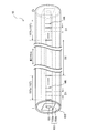
- FIG. 2 is a diagram showing a detailed configuration of an optical fiber used in a laser oscillator.
- the optical fiber 15 has a core 151, a clad 153, a coat layer 155, and a grating region 157.
- the core 151 is excited by the excitation light L2 introduced from the light introducing unit 13 and generates a laser beam L1 having a wavelength determined by the substance doped in the core 151. That is, the core 151 functions as a laser medium of the laser oscillator 1.
- the core 151 is a fluoride fiber doped with a rare earth element.
- ZBLAN glass is a glass containing zirconium (Zr), barium (Ba), lanthanum (La), aluminum (Al), and sodium (Na) as main components.
- the core 151 is excited by the excitation light L2, so that the laser light L1 having a mid-infrared wavelength (specifically, around 2.8 ⁇ m) is emitted. Can be generated.
- the clad 153 is a layer formed so as to cover the core 151 on the outer periphery of the core 151 and having a refractive index smaller than that of the core 151.
- the clad 153 includes a first clad 153a and a second clad 153b.
- the first cladding 153a is a ZBLAN glass that covers the outer periphery of the core 151.
- the first cladding 153a has a smaller refractive index than the core 151. Therefore, the first clad 153a confines the laser light L1 inside the core 151 by reflecting the laser light L1 generated inside the core 151 at the interface with the core 151.
- the first cladding 153a has a quadrangular shape having four sides (four linear portions) in a cross section perpendicular to the length direction (FIG. 2).
- the first cladding 153a has a rectangular cross section in a direction perpendicular to the length direction, but is not limited thereto.
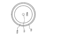
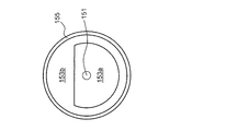
- the first cladding 153a is formed by cutting out a part of the circumference of a circle (FIG. 3A), a D-shape (FIG. 3B), a polygon (for example, an octagon (FIG. 3C)), or a D-shape. 3D) and the like.
- FIG. 3A is a diagram illustrating a first example of a cross-sectional shape of a first clad.
- FIG. 3B is a diagram showing a second example of the cross-sectional shape of the first clad.
- FIG. 3C is a diagram illustrating a third example of the cross-sectional shape of the first clad.
- FIG. 3D is a diagram illustrating a fourth example of the cross-sectional shape of the first clad.
- the second cladding 153b is a resin that covers the outer periphery of the first cladding 153a.
- the second cladding 153b is made of a low refractive index fluoride resin.
- the second cladding 153b has a smaller refractive index than the first cladding 153a. Therefore, the second cladding 153b reflects the pumping light L2 incident on the cladding 153 at the interface with the first cladding 153a, thereby confining the pumping light L2 inside the first cladding 153a and the core 151. Thereby, the excitation light L2 can pass through the inside of the first cladding 153a and the core 151 a plurality of times.
- the coating layer 155 is a resin (for example, acrylic resin) coating provided on the outermost periphery of the optical fiber 15.
- the coat layer 155 is a layer that prevents the optical fiber 15 (the first clad 153a and the core 151 made of ZBLAN glass) having deliquescence from coming into contact with moisture in the air.
- the coating layer 155 can prevent the optical fiber 15 from deteriorating.
- the grating area 157 is an area that reflects a part of the laser light L1 that has propagated through the core 151.
- the grating area 157 has a first grating area 157a and a second grating area 157b.
- the first grating region 157a is formed inside the core 151 near the entrance I of the excitation light L2 of the optical fiber 15.
- the first grating region 157a includes a plurality of refractive index modulation regions HR formed with a first interval D1.
- the refractive index modulation region HR is a region having a refractive index different from the refractive index of the core 151. That is, in the first grating region 157a, portions having a relatively high refractive index and portions having a relatively low refractive index are alternately arranged.
- the reflected light from a certain refractive index modulation region HR in the grating region 157 and the reflected light from an adjacent refractive index modulation region HR arranged at a first interval D1 have the same phase at the same location.
- the two reflected lights increase their mutual intensity by interference. Such reinforcement of the intensity of the reflected light occurs in the grating region 157, and as a result, light reflection occurs.
- the second grating region 157b is formed inside the core 151 near the exit O of the laser light L1 of the optical fiber 15. That is, the second grating region 157b is formed at a second interval D2 from the first grating region 157a in the length direction of the core 151. As shown in FIG. 3, the second grating region 157b includes a plurality of refractive index modulation regions HR formed at a first interval D1, similarly to the first grating region 157a.
- the second grating region 157b is a laser beam having a wavelength determined by the first interval D1 of the laser beam L1 propagating in the exit O direction through the core 151 based on the same principle as the reflection principle of the first grating region 157a. A part of the light L1 can be reflected toward the entrance I of the core 151. Of the laser light L1 propagating in the exit O direction, the laser light L1 that has passed through the second grating region 157b is output from the exit O. In order to output more laser light L1 from the exit O, it is preferable that the reflectance of the laser light L1 in the second grating region 157b is smaller than the reflectance in the first grating region 157a. Specifically, it is preferable that the formation length of the second grating region 157b is shorter than the formation length of the first grating region 157a.
- the core 151 of the optical fiber 15 has the first grating region 157a on the entrance I side of the excitation light L2, and has the second grating region 157b on the exit O side of the laser light L1, so that the specific wavelength can be increased.
- the laser beam L1 can be amplified between the first grating region 157a and the second grating region 157b. That is, laser oscillation of the laser light L1 can be realized in the core 151 without disposing a mirror or the like at any end of the optical fiber 15.
- the laser oscillator 1 including the optical fiber 15 of the present embodiment can reduce loss. As a result, laser light L1 having a higher intensity can be output efficiently.
- FIG. 4A is an overall view of an apparatus for forming a refractive index modulation region.
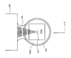
- FIG. 4B is an enlarged view near the objective lens in the forming apparatus.
- the forming apparatus 200 mainly includes a reaction light source 201, a moving table 203, an objective lens 205, and a control unit 209.
- the reaction light source 201 is a light source that outputs the reaction light L3.
- the reaction light L3 causes a chemical reaction at a location of the core 151 where the reaction light L3 is irradiated, and makes the refractive index of the location different from the refractive index of the core 151.
- the reaction light L3 has sufficient energy with respect to the core 151 to cause a reaction for modulating the refractive index.
- the wavelength of the reaction light L3 is preferably short.
- the reaction light L3 interacts with the other portions forming the path of the reaction light L3, that is, the cladding 153 and the coat layer 155 of the optical fiber 15 and is not absorbed. That is, the wavelength of the reaction light L3 is preferably not short enough to interact with the cladding 153 and the coat layer 155. Therefore, as the reaction light L3, a light having the minimum wavelength that is absorbed by the cladding 153 and the coat layer 155 and does not interact with each other is selected.
- a general processing laser (YAG laser) is used as the reaction light source 201 in consideration of the condition of the reaction light L3 for the optical fiber 15 and the availability of the light source used as the reaction light source 201.
- the light from the reaction light source 201 is converted to a higher harmonic, and the reaction light L3 having a wavelength of 515 nm is output.
- the reaction light L3 can be focused inside the core 151 with a smaller spot diameter without changing the quality of the clad 153 and the coat layer 155.
- the reaction light source 201 generates femtosecond short-pulse laser light (pulse width: 400 fs (femtosecond)) having the above wavelength as the reaction light L3. Further, the output intensity of the reaction light L3 is adjusted, for example, in the range of 0.01 ⁇ J to 1 ⁇ J. The output intensity of the reaction light L3 is appropriately adjusted according to the type of the optical fiber 15 forming the refractive index modulation region HR.
- the moving table 203 is a stage that can move in the length direction of the optical fiber 15 (X direction in FIG. 4A) and in the height direction perpendicular to it (Z direction in FIG. 4A).
- a moving table (stage) using a piezo element or the like as a driving source can be used as the moving table 203. Accordingly, the optical fiber 15 can be moved with high precision in the length direction and the height direction, so that the refractive index modulation region HR can be formed at an accurate position inside the core 151 of the optical fiber 15.
- the optical fiber 15 forming the refractive index modulation region HR is arranged on the movable table 203.
- a pair of holding members 204 are fixed on the upper surface of the moving table 203 in the X direction.
- the pair of holding members 204 are clamps that hold the optical fiber 15 at two places while applying a slight tension in the X direction (length direction). By applying tension in the length direction (X direction) of the optical fiber 15, the optical fiber 15 can be prevented from being held between the holding members 204 in a bent state.
- the objective lens 205 is a lens that focuses the reaction light L3 propagated from the reaction light source 201 through the optical path changing member 207 (for example, a prism mirror) into the core 151. Further, as shown in FIG. 4B, a matching layer ML is disposed between the objective lens 205 and the coat layer 155 of the optical fiber 15.
- the matching layer ML is formed of, for example, an immersion oil (a Cargill standard refraction liquid) (an example of a liquid material) used for forming an “immersion objective lens” in an optical microscope.
- the refractive index of the matching layer ML is preferably larger than the refractive index (1.0) of air, more preferably in the range of 1.3 to 1.6, and is preferably about 1.5, which is close to the refractive index of the coat layer 155. Most preferred. With a refractive index greater than air, the matching layer ML can increase the numerical aperture of the objective lens 205. In this embodiment, immersion oil having a refractive index of about 1.5 is used as the matching layer ML.
- the matching layer ML which is immersion oil, is held by the objective lens 205 and the coat layer 155 of the optical fiber 15 due to the surface tension.
- the refractive index between the objective lens 205 and the coating layer 155 of the optical fiber 15 is higher than that of air.
- the control unit 209 includes, for example, a CPU, a RAM, a ROM, a storage device (SSD, hard disk, etc.), a computer system including various interfaces, a control unit for the reaction light source 201, and a control unit for the moving table 203. , The reaction light source 201, the moving table 203, and the objective lens 205 are controlled. Note that the control unit of the reaction light source 201 and the control unit of the movable base 203 are controlled by executing a program (the program is stored in a storage device of the computer system) in the computer system of the control unit 209. You may.
- the forming apparatus 200 further includes a camera (not shown) above the optical path changing member 207. With this camera, processing marks formed by the reaction light L3 can be observed via the objective lens 205. As a result, the appropriate position of the core 151 can be irradiated with the reaction light L3.
- the forming apparatus 200 further includes a white light source (not shown) for introducing white light from one side of the optical fiber 15 to the core 151.
- a white light source (not shown) for introducing white light from one side of the optical fiber 15 to the core 151.
- the reflection or transmission spectrum of the optical fiber 15 can be observed.
- the quality of the formed grating region 157 can be confirmed during the manufacturing by the forming apparatus 200, and the manufacturing time can be reduced and the quality of the grating region 157 can be stabilized.
- the formed grating region 157 may be evaluated by measuring the laser oscillation output generated by introducing the excitation light L2 into the cladding 153 in the forming apparatus 200. Specifically, the evaluation of the grating region 157 using the excitation light L2 can be performed by introducing an evaluation device 300 described later into the forming device 200.
- the moving table 203 may be movable in the Y direction.
- a two-dimensional refractive index modulation region HR can be formed in the cross section of the core 151.
- the forming apparatus 200 moves the focal position of the reaction light L3 by the moving table 203 and / or the objective lens 205, and moves the focal position of the reaction light L3 to an arbitrary position inside the core 151 of the optical fiber 15.
- the refractive index can be different.
- an arbitrary form of the refractive index modulation region HR can be formed inside the core 151.
- FIG. 5A is a diagram illustrating an example of a configuration of the evaluation device.
- the evaluation device 300 is incorporated in the forming device 200 described above. Therefore, the evaluation device 300 causes the white light L4 to enter the clad 153 while forming the grating region 157 in the forming device 200, and measures the spectrum intensity of the transmitted light L1 ′ transmitted through the grating region 157, thereby causing laser oscillation.
- the performance of the optical fiber 15 as a medium can be evaluated.
- the evaluation device 300 includes a white light source 301, an optical waveguide fiber 303, an introduction unit 305, and a first light measurement unit 307.
- the white light source 301 outputs white light L4.
- the white light L4 has a wavelength in the range of 1000 nm to 5000 nm including the wavelength of light that can be excited by the optical fiber 15.
- a white light LED light source for example, a white light LED light source, a white electric lamp, or the like can be used.
- the optical waveguide fiber 303 is an optical fiber that guides the white light L4 output from the white light source 301 to the introduction unit 305.
- the introduction unit 305 is arranged near the other end of the optical fiber 15 opposite to the one end where the grating region 157 is formed, and introduces the white light L4 into the clad 153 from the other end.
- the first light measurement unit 307 is, for example, an optical spectrum analyzer that measures the spectrum intensity of the transmitted light L1 ′ that has passed through the grating area 157.
- FIG. 5B is a diagram illustrating another example of the evaluation device.
- a mirror 305a is provided in the introduction unit 305.
- the mirror 305a is a half mirror, a dichroic mirror, or the like, and reflects the reflected light L1 ′′ reflected by the grating area 157 in a direction different from the white light L4.
- the mirror 305a transmits the white light L4.
- the second light measurement unit 309 is, for example, an optical spectrum analyzer that measures the spectral intensity of the reflected light L1 ′′ reflected by the grating area 157 and reflected by the mirror 305a.
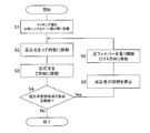
- FIG. 6 is a flowchart showing a method for manufacturing an optical fiber.
- the optical fiber 15 forming the refractive index modulation region HR is held by the holding member 204 of the forming apparatus 200 without peeling the coat layer 155. That is, in the present embodiment, in a state where the optical fiber 15 is coated with the coating layer 155, the core 151 is irradiated with the reaction light L3 to form the refractive index modulation region HR.
- step S1 the objective lens 205 is brought close to the optical fiber 15, and a matching layer ML is arranged between the objective lens 205 and the coat layer 155 of the optical fiber 15.
- immersion oil for forming the matching layer ML is injected into a gap between the objective lens 205 and the optical fiber 15.
- the immersion oil that is, the matching layer ML is held between the objective lens 205 and the coat layer 155 of the optical fiber 15 arranged close to each other by the surface tension.
- an air layer having a low refractive index is formed between the objective lens 205 and the coat layer 155 of the optical fiber 15 by using the surface tension. Without this, the matching layer ML can be easily formed.
- the reaction light source 201 After disposing the matching layer ML between the objective lens 205 and the coating layer 155 of the optical fiber 15, in step S2, the reaction light source 201 generates reaction light L3. After passing through the objective lens 205, the reaction light L3 generated by the reaction light source 201 propagates inside the matching layer ML.
- the refractive index of the matching layer ML is about 1.5, which is close to the refractive index of the coat layer 155 (the objective lens 205 and the clad 153). Therefore, the refraction at the interface between the matching layer ML and the coat layer 155 is smaller than the refraction at the interface between the air and the coat layer 155 when the matching layer ML is not provided.
- the reaction light L3 can be focused inside the core 151 with a small spot diameter.
- the moving table 203 is moved in the Z direction (an example of a direction perpendicular to the length direction of the core 151) in step S3. Accordingly, the spot SP of the reaction light L3 moves inside the core 151 in the diameter direction of the core 151.
- the moving speed when the spot SP of the reaction light L3 is moved in the Z direction depends on the frequency (frequency) of outputting the short-pulse reaction light L3 from the reaction light source 201 and / or the material constituting the optical fiber 15 or the like. It is determined based on. In the present embodiment, the moving speed is in the range of 30 ⁇ m to 3 mm / sec. In the present embodiment, the reaction light L3 is moved at the above moving speed, and the reaction light L3 is reciprocated 1 to 100 times in the Z direction in the core 151 (diameter of the core 151: 15 ⁇ m).
- the movement range of the reaction light L3 in the Z direction extends not only inside the core 151 but also to a part of the first cladding 153a.
- FIG. 7 is a diagram illustrating an example of the refractive index modulation region formed when the spot of the reaction light is moved in the diameter direction of the core.
- the moving speed when moving the spot SP of the reaction light L3 in the Z direction within a predetermined range, it is possible to form the refractive index modulation region HR uniform in the Z direction.
- the refractive index modulation region HR is not uniform in the Z direction.
- the inhomogeneous refractive index modulation region HR scatters the laser light L1 and lowers the laser oscillation efficiency in the optical fiber 15.
- the refractive index modulation region HR can be extended to a part of the first clad 153a.
- the laser light L1 is reflected at the interface between the core 151 and the first cladding 153a, the laser light L1 leaks from the outer periphery of the core 151 to the first cladding 153a by about a half wavelength of the laser light L1. Therefore, by extending the refractive index modulation region HR toward the first cladding 153a, the laser beam L1 leaked to the first cladding 153a can be reflected by the refractive index modulation region HR.
- step S4 After executing steps S2 and S3 to form one refractive index modulation region HR, it is determined in step S4 whether or not to form a further refractive index modulation region HR. In the present embodiment, whether or not to continue the formation of the refractive index modulation region HR is determined based on whether or not the number of formed refractive index modulation regions HR has reached a predetermined number. In another embodiment, the magnitude of the laser oscillation output generated in the optical fiber 15 in which the grating region 157 is formed may be used as a criterion for determining whether to continue formation of the refractive index modulation region HR.
- the reflection spectrum of the grating region 157 may be used as a criterion for determining whether to continue formation of the refractive index modulation region HR. For example, whether or not the intensity of light having a specific wavelength reflected by the grating region 157 has reached a desired level may be used as a criterion for determining whether to continue formation of the refractive index modulation region HR.
- the spectral shape of the light (the peak wavelength of the light, the half-width of the spectrum, the presence or absence of side lobes, and the like) may be used as a criterion.
- step S4 When it is determined that the formation of the refractive index modulation region HR is not to be continued based on the above determination criteria ("No" in step S4), the process of forming the refractive index modulation region HR is ended. On the other hand, when it is determined that the formation of the refractive index modulation region HR is to be continued (“Yes” in step S4), the irradiation of the reaction light L3 is stopped in step S5. Thereafter, in step S6, the movable table 203 is moved in the X direction, and the optical fiber 15 is moved in the length direction by the first interval D1.
- the above steps S2 to S4 are executed at the position in the length direction to form another refractive index modulation region HR.
- a plurality of refractive index modulation regions HR can be formed in the grating region 157 by separating the adjacent refractive index modulation regions HR by the first distance D1.
- Example (7-1) Conditions for Forming Refractive Index Modulated Region in Example
- the optical fiber 15 forming the grating region 157 was made of ZBLAN glass in which a core 151 having a square cross section was doped with erbium.
- the optical fiber 15 used in the embodiment is a double clad optical fiber in which the first clad 153a is a ZIBLAN glass and the second clad 153b is a resin.
- the matching layer ML is formed by applying a low auto-fluorescent immersion oil (refractive index: 1.515, viscosity: 450 mm 2 / s, manufactured by Olympus (registered trademark)) to the surface between the objective lens 205 and the coating layer 155 of the optical fiber 15. It was held by tension.
- a low auto-fluorescent immersion oil reffractive index: 1.515, viscosity: 450 mm 2 / s, manufactured by Olympus (registered trademark)
- the refractive index modulation region HR was formed using a reaction light L3 having a pulse width of 400 fs and a wavelength of 515 nm.
- the intensity of the reaction light L3 was adjusted at around 0.5 ⁇ J while confirming the irradiation mark by the reaction light L3.
- the interval (first interval D1) between the adjacent refractive index modulation regions HR was 970 nm. This interval can reflect the laser light L1 (wavelength: about 2.8 ⁇ m mid-infrared light) excited by the core 151 of erbium-doped ZBLAN glass using first-order diffraction.
- the moving speed of the spot SP of the reaction light L3 in the Z direction was 30 ⁇ m / sec. In this embodiment, the spot SP of the reaction light L3 is reciprocated once in the Z direction at the above moving speed to form the refractive index modulation region HR.
- Evaluation Results (7-2-1) Optical Microscope Image of Grating Area
- evaluation results of the optical fiber 15 having the grating area 157 manufactured in the example will be described.
- an optical microscope image of the grating region 157 formed in the optical fiber 15 will be described with reference to FIG.
- FIG. 8 is an optical microscope image of the grating region of the optical fiber.
- the grating region 157 corresponds to a portion where a line (vertical line) light and dark perpendicular to the length direction of the core 151 appears. Since the vertical line brightness is clear at a position corresponding to the grating region 157, it can be seen that a uniform refractive index modulation region HR is formed in the diameter direction of the core 151 using the above manufacturing conditions.
- the formation state of the grating region 157 can be visually confirmed by optical microscope observation, but it is difficult to accurately specify the microscopic structures of the grating region 157 and the refractive index modulation region HR. It is.
- a method of specifying the microscopic structures of the grating region 157 and the refractive index modulation region HR for example, observation with an electron microscope can be considered. To observe them with an electron microscope, a part of the core 151 is taken out. There is a need.
- the cladding 153 In order to take out a part of the core 151 to the outside, the cladding 153 needs to be peeled off, and the microscopic structures of the grating region 157 and the refractive index modulation region HR are destroyed by the operation up to observation with an electron microscope. The possibility is great. Further, in the case of an optical fiber formed of a deliquescent material such as ZBLAN glass, the refractive index modulation region HR is altered before the refractive index modulation region HR is taken out, and its structure changes.
- the formation is performed by evaluating the performance based on the optical characteristics of the grating region 157.
- the obtained refractive index modulation region HR was evaluated.
- the intensity of the light component of the wavelength (2.8 ⁇ m) is measured by the first light measuring unit 307, and the intensity of the light component of the wavelength corresponding to the laser light L 1 of the white light L 4 before transmission is transmitted to the first light measuring unit 307.
- the reflectance was calculated by dividing the difference between the measured intensity of the light component of the wavelength corresponding to the laser light L1 and the intensity of the light component of the wavelength corresponding to the laser light L1 of the white light L4 before transmission. .
- FIG. 9 shows the relationship between the formation length of the grating region 157 and the reflectance of the laser beam L1 in the example. As shown in FIG. 9, even if the formed length is about 2.0 mm, the reflectance of the grating region 157 is close to 1. This indicates that the reflectance of one refractive index modulation region HR included in the grating region 157 can be increased by using the above-described conditions for forming the refractive index modulation region HR. It also shows that a laser beam L1 with sufficient intensity can be obtained even in the grating region 157 having a short formation length.
- the performance of the grating region 157 was evaluated based on the spectrum of white light L4 transmitted through the grating region 157 (transmission spectrum of the grating region).
- the reflection spectrum of the grating region 157 was obtained by using the above-described evaluation device 300. Specifically, the component intensity of each wavelength included in the white light L4 transmitted through the grating region 157 is measured by the first light measurement unit 307, and the component intensity of each wavelength included in the white light L4 before transmission is determined. The quotient of the intensity of the corresponding wavelength component of the white light L4 measured by the one light measurement unit 307 was calculated as the transmittance at the wavelength. After that, the above-described calculation of the transmittance was repeatedly performed for all the wavelengths included in the white light L4 to obtain a transmission spectrum.
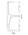
- FIG. 10 shows a transmission spectrum of the grating region 157 in the example.
- the transmittance of the grating region 157 is significantly reduced only at one specific wavelength (2.8 ⁇ m). That is, the reflectance of the grating region 157 is significantly increased at one wavelength.
- the grating region 157 having high wavelength selectivity of reflected light can be formed by using the above-described conditions for forming the refractive index modulation region HR.
- the grating region 157 of the example shows that the laser beam L1 having a wavelength of 2.8 ⁇ m can be reflected by reflection using first-order diffraction.
- the adjacent refractive index modulation regions HR may be separated from each other. Indicate that the refractive index modulation region HR is appropriately formed without overlapping.
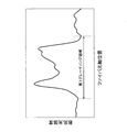
- red light (wavelength: 650 nm) was incident from the first grating region 157a side (entrance I side) and propagated through the core 151, and the scattered light intensity of the red light in each of the grating regions 157a and 157b was measured. .
- FIG. 11A shows the scattered light intensity of the first grating region 157a including the refractive index modulation region HR formed under non-optimal conditions.
- FIG. 11B shows the scattered light intensity of the second grating region 157b including the refractive index modulation region HR formed under the optimum condition.
- the laser light L1 is scattered in the grating region 157, and the core 151 It can be seen that the ratio of the laser light L1 that can propagate inside is reduced. That is, when the refractive index modulation region HR is not uniform inside the core 151, the oscillation efficiency of the laser light L1 is reduced.
- the refractive index modulation region HR is formed homogeneously.
- the refractive index modulation region HR can be made uniform inside the core 151, so that the laser light L1 does not scatter in the grating region 157, and the inside of the core 151
- the proportion of the laser beam L1 that can propagate can be increased. That is, when the refractive index modulation region HR is uniform inside the core 151, the oscillation efficiency of the laser beam L1 can be increased.
- the method for forming the refractive index modulation region HR has the following advantages as compared with the conventional method.
- a sufficient laser medium and an oscillator can be provided.
- the optical fiber 15 having excellent performance can be manufactured.
- a matching layer ML having a refractive index of about 1.5 is disposed between the objective lens 205 and the coating layer 155 of the optical fiber 15 so that the objective lens
- the spot diameter of the reaction light L3 inside the core 151 can be reduced.
- 515 nm which is the minimum wavelength that is not absorbed by the coat layer 155 and the clad 153, as the wavelength of the reaction light L3, the reaction light L3 is not degraded by the reaction light L3 without deteriorating the coat layer 155 and the clad 153. Can be focused inside the core 151 with a smaller spot diameter.
- Focusing the reaction light L3 with a small spot diameter inside the core 151 as described above means that the inside of the core 151 can be irradiated with the reaction light L3 having a large fluence. That is, by condensing the reaction light L3 into the core 151 with a small spot diameter as described above, the reaction of changing the refractive index is concentrated on the portion of the core 151 irradiated with the reaction light L3. Can be generated. As a result, the refractive index modulation region HR having a high reflectance and a small size can be formed inside the core 151.
- the refractive index modulation region HR having a high reflectivity and a small size can be formed inside the core 151, even if the number of the refractive index modulation regions HR formed in the grating region 157 is reduced, it is sufficient for laser oscillation.
- the grating region 157 having a high reflectivity can be formed.
- the optical fiber 15 has the grating region 157 with a formed length of at least about 1.5 mm to 2.0 mm, the laser medium and the resonator of the fiber laser are used. With sufficient performance. If the formation length of the grating region 157 can be reduced, the manufacturing time of the optical fiber 15 having the grating region 157 can be reduced.
- the grating region 157 Since the formation length of the grating region 157 can be reduced, the grating region 157 with stable quality can be formed. This is because if the formation length of the grating region 157 increases, the characteristics of the grating region 157 differ depending on the position in the length direction due to the distortion of the structure of the optical fiber 15 (twist, deviation of the position of the core 151, etc.). Because there is.
- the method according to the present embodiment in which the small-sized refractive index modulation region HR can be formed inside the core 151, is different from the conventional method in that the adjacent refractive index modulation regions HR overlap in the length direction of the core 151. Can be avoided. As a result, even if the interval (the first interval D1) between the adjacent refractive index modulation regions HR is set as the interval (about 1 ⁇ m) for reflecting the mid-infrared laser light L1 by using first-order diffraction, the adjacent refraction is used. The rate modulation regions HR do not overlap.
- the refractive index modulation regions HR do not overlap, so that only a specific wavelength determined by the first interval D1 is used. Can oscillate the laser light L1. That is, an ideal laser beam with excellent spectral characteristics can be output.
- the homogeneous refractive index modulation region HR can be formed inside the core 151.
- scattering of the laser beam L1 does not occur in the refractive index modulation region HR, so that an ideal laser beam having strong directivity and excellent spectral characteristics can be output.
- an arbitrary cross-sectional shape such as a circle, a D-shape, a polygon, or a star is used as a cross-sectional shape in a direction perpendicular to the length direction of the first clad 153a. But it is not limited to this.
- the reaction light L3 that forms the refractive index modulation region HR in the core 151 is perpendicularly incident from a plane having no curvature of the first cladding 153a.
- FIG. 12 is a diagram illustrating an example of a method of incident reaction light according to the second embodiment.
- the first cladding 153a preferably has at least one linear portion in a cross-sectional shape in a direction perpendicular to the length direction. That is, the cross-sectional shape of the first cladding 153a is preferably a D-shape, a polygon (for example, a quadrangle, an octagon, or the like).
- the spot shape of the reaction light L3 inside the core 151 is suppressed from being distorted, and the spot of the reaction light L3 inside the core 151 is suppressed. Shape can be reduced.
- the reaction light L3 can be appropriately focused inside the core 151 without distorting the spot shape.
- the first embodiment and the second embodiment have the following configurations and functions in common.
- a refractive index modulation region HR an example of a refractive index modulation region having a refractive index different from the refractive index of the core 151 is provided inside the core 151 (an example of the core).
- the method for manufacturing the optical fiber 15 includes the following steps.
- the objective lens 205 (an example of the objective lens) for condensing the reaction light L3 (an example of the reaction light) that changes the refractive index of the core 151 and the resin coat layer 155 (coat layer) provided on the outermost periphery of the optical fiber 15 And a step of arranging a matching layer ML (an example of a matching layer) having a refractive index close to that of the coat layer 155 (for example, step S1).
- a step of irradiating the reaction light L3 toward the inside of the core 151 to form the refractive index modulation region HR (for example, steps S2 to S6).
- the reaction light L3 is applied to the inside of the core 151 without peeling the outermost coat layer 155 of the optical fiber 15. This can prevent the optical fiber 15 from deteriorating during the formation of the refractive index modulation region HR inside the core 151. Further, it is not necessary to re-form the coat layer 155 after forming the refractive index modulation region HR.
- the refractive index of the space between the objective lens 205 and the coat layer 155 can be made higher than that of air.
- a small area inside the core 151 can be irradiated with the reaction light L3 having a high intensity. Therefore, a small refractive index modulation region HR having a large reflectance is formed. It can be formed inside the core 151.
- sufficient light reflection can be obtained even if the number of formed refractive index modulation regions HR inside the core 151 is small.
- the number of refractive index modulation regions formed inside the core can be reduced, it is not necessary to form the refractive index modulation region HR over a wide range in the length direction of the core.
- the variation in the refractive index modulation region HR due to the variation in the characteristics in the length direction of the optical fiber 15 is small, and the wavelength selectivity of the laser light that can oscillate is high.
- the small refractive index modulation regions HR can be formed inside the core 151, even if the distance between the adjacent refractive index modulation regions HR is reduced, these refractive index modulation regions HR do not overlap. As a result, in the optical fiber 15 manufactured by the above-described method, even a short-wavelength laser beam can be reflected by low-order diffraction, so that the wavelength selectivity of the short-wavelength laser beam that can oscillate is high.
- the present invention has been described above, but the present invention is not limited to the above embodiment, and various changes can be made without departing from the gist of the invention.
- a plurality of embodiments and modifications described in this specification can be arbitrarily combined as needed.
- the material of the optical fiber 15 and the first distance D1 between the refractive index modulation regions HR adjacent to each other can be appropriately changed according to the wavelength of the laser light L1 to be output by the laser oscillator 1.
- the conditions for forming the refractive index modulation region HR (for example, the wavelength, irradiation time, intensity, and the like of the reaction light L3) can be appropriately changed according to the optical characteristics of the material of the optical fiber 15.
- the method of forming the refractive index modulation region HR according to the above-described first embodiment and the second embodiment is not limited to the fluoride fiber, as long as the refractive index modulation can be induced by the reaction light L3. Applicable.
- the present invention can be applied not only to optical fibers but also to various optical waveguides.
- the moving table 203 may be movable in the diameter direction (Y direction) of the optical fiber 15 in addition to the length direction (X direction) and the height direction (Z direction) of the optical fiber 15. .
- the reaction light L3 may be moved two-dimensionally in the height direction and the diameter direction of the optical fiber 15 (that is, in the YZ plane).
- a two-dimensional refractive index modulation region HR can be formed in a cross section perpendicular to the length direction of the optical fiber 15.
- the present invention can be widely applied to a laser oscillator using an optical fiber as a laser medium and a resonator.
Landscapes
- Physics & Mathematics (AREA)
- General Physics & Mathematics (AREA)
- Optics & Photonics (AREA)
- Lasers (AREA)
- Optical Fibers, Optical Fiber Cores, And Optical Fiber Bundles (AREA)
Abstract
屈折率変調領域の形成中に光ファイバーが劣化することを防止しつつ、高い反射率を有する屈折率変調領域を形成する。屈折率変調領域HRを設けた光ファイバー15の製造方法は、コア151の屈折率を変化させる反応光L3を集光させる対物レンズ205と光ファイバー15のコート層155との間に、コート層155の屈折率と近い屈折率を有するマッチング層MLを配置するステップと、反応光L3をコア151内部に向けて照射して、屈折率変調領域HRを形成するステップと、を含む。
Description
本発明は、レーザ発振器に使用される光ファイバーの製造方法に関する。
従来、光を長さ方向に伝搬させるコアを有する光ファイバーにおいて、当該コアの内部にコアの屈折率よりも高い(又は低い)屈折率を有する複数の領域(屈折率変調領域と呼ぶ)が所定の間隔を空けて形成されたものが知られている。コア内部に光が伝搬するとき、この複数の屈折率変調領域は当該光に対して回折格子として働く。従って、上記のような複数の屈折率変調領域が形成された光ファイバーは、「ファイバーブラッググレーティング(Fiber Bragg Grating、FBG)」と呼ばれる。
複数の屈折率変調領域を所定の間隔を空けて形成した光ファイバーに光を伝搬させると、当該光のうち、光ファイバーの屈折率と上記所定の間隔にて決まる波長を有する光を反射光として取り出すことができる。また、例えば、コアに希土類などを添加した光ファイバーの両端近傍に上記所定の間隔で複数の屈折率変調領域を形成し、当該光ファバーに適切な励起光を導入すると、光ファイバーのコア内を伝搬した発光のうち、上記所定の間隔にて決まる波長を有する光を光ファイバー内で往復させて増幅できる。すなわち、レーザ発振を光ファイバー内にて実現できる。
特許文献1には、光ファイバーのコア層にパルスレーザ光を照射して当該コア層において化学反応を起こさせることにより、コア層内に屈折率変調領域を形成する技術が開示されている。特許文献1では、1つの屈折率変調領域を形成した後、光ファイバーをグレーティング周期分だけ移動させ、コア層に再度パルスレーザ光を照射することにより、グレーティング周期だけ間隔を空けて複数の屈折率変調領域を形成している。
特許文献1などに開示された従来の屈折率変調領域の形成方法では、光ファイバーのクラッドの外表面に設けられた保護用被膜を剥離した後に、光ファイバーのコア内部にパルスレーザ光を照射していた。この場合、潮解性を有する材料が光ファイバーに用いられていると、空気中の湿度により、屈折率変調領域の形成中に光ファイバーが劣化していた。また、さらなる劣化を防ぐために、屈折率変調領域を形成後に、光ファイバーの外周を保護用被膜などで再度被膜する必要があった。
また、従来の形成方法では、パルスレーザ光をコア内部に十分に集光できなかったために、コア内部にて弱い反応しか発生できず、高い反射率を有する屈折率変調領域を形成することができなかった。そのため、レーザ発振器の発振媒体として十分な性能を発揮する光ファイバーを製造するために、コア内部に多数の屈折率変調領域を形成する必要があった。
コア内部に多数の屈折率変調領域を形成することは、コアの長さ方向の広範囲にわたって屈折率変調領域を形成することを意味する。従って、コア内部に多数の屈折率変調領域を形成すると、コアの長さ方向の特性変動のために、屈折率変調領域の特性(特に反射率)がコアの長さ方向で異なることとなり、波長選択性の高いレーザ発振を得ることが難しかった。
また、コア内部に多数の屈折率変調領域を形成する場合には、コア内部に繰り返しパルスレーザを照射する必要があるので、レーザ発振器の発振媒体としての光ファイバーの製造に時間がかかっていた。
コア内部に多数の屈折率変調領域を形成することは、コアの長さ方向の広範囲にわたって屈折率変調領域を形成することを意味する。従って、コア内部に多数の屈折率変調領域を形成すると、コアの長さ方向の特性変動のために、屈折率変調領域の特性(特に反射率)がコアの長さ方向で異なることとなり、波長選択性の高いレーザ発振を得ることが難しかった。
また、コア内部に多数の屈折率変調領域を形成する場合には、コア内部に繰り返しパルスレーザを照射する必要があるので、レーザ発振器の発振媒体としての光ファイバーの製造に時間がかかっていた。
さらに、従来の形成方法では、パルスレーザ光をコア内部に十分に集光できなかったために、コア内部に形成される屈折率変調領域の長さ方向の幅が大きくなっていた。そのため、隣接する屈折率変調領域同士が重複しないよう、隣接する屈折率変調領域の間の距離を大きくする必要があった。
一般的に、光ファイバー内で発振できるレーザ光の波長は、隣接する屈折率変調領域の間の距離によって決まる。よって、従来の方法により屈折率変調領域を形成した光ファイバーにおいて短波長のレーザ光を発振させるには、高次の回折による反射を利用する必要があった。高次の回折による反射を利用した場合には、屈折率変調領域は、目的の波長以外の他の波長の光も(強く)反射するため、波長選択性の高いレーザ発振を得ることが難しかった。
一般的に、光ファイバー内で発振できるレーザ光の波長は、隣接する屈折率変調領域の間の距離によって決まる。よって、従来の方法により屈折率変調領域を形成した光ファイバーにおいて短波長のレーザ光を発振させるには、高次の回折による反射を利用する必要があった。高次の回折による反射を利用した場合には、屈折率変調領域は、目的の波長以外の他の波長の光も(強く)反射するため、波長選択性の高いレーザ発振を得ることが難しかった。
また、隣接する屈折率変調領域の間の距離を大きくする必要があるため、十分な反射率を有する光ファイバーを製造するには、コアの長さ方向の広範囲にわたり屈折率変調領域を形成する必要があり、上記と同様の問題を生じる。
本発明の目的は、ファイバーブラッググレーティングを有する光ファイバーの製造方法において、屈折率変調領域の形成中に光ファイバーが劣化することを防止しつつ、高い反射率を有する屈折率変調領域を形成することにある。
以下に、課題を解決するための手段として複数の態様を説明する。これら態様は、必要に応じて任意に組み合せることができる。
本発明の一見地に係る光ファイバーの製造方法は、コア内部に屈折率変調領域を設けた光ファイバーの製造方法である。屈折率変調領域は、コアの屈折率とは異なる屈折率を有する領域である。光ファイバーの製造方法は、以下のステップを含む。
◎対物レンズとコート層との間に、コート層の屈折率と近い屈折率を有するマッチング層を配置するステップ。
◎反応光をコア内部に向けて照射して屈折率変調領域を形成するステップ。
上記において、対物レンズは、コアの屈折率を変化させる反応光を集光させるレンズである。コート層は、光ファイバーの最外周に設けられた樹脂製の層である。
本発明の一見地に係る光ファイバーの製造方法は、コア内部に屈折率変調領域を設けた光ファイバーの製造方法である。屈折率変調領域は、コアの屈折率とは異なる屈折率を有する領域である。光ファイバーの製造方法は、以下のステップを含む。
◎対物レンズとコート層との間に、コート層の屈折率と近い屈折率を有するマッチング層を配置するステップ。
◎反応光をコア内部に向けて照射して屈折率変調領域を形成するステップ。
上記において、対物レンズは、コアの屈折率を変化させる反応光を集光させるレンズである。コート層は、光ファイバーの最外周に設けられた樹脂製の層である。
上記の製造方法においては、光ファイバーの最外周のコート層を剥離することなく、反応光のコア内部への照射を行っている。これにより、コア内部に屈折率変調領域を形成中に光ファイバーが劣化することを防止できる。また、屈折率変調領域を形成後に、コート層を再形成する必要がなくなる。
また、対物レンズとコート層との間にマッチング層が配置されることにより、対物レンズとコート層との間の空間の屈折率を高くできる。その結果、対物レンズの開口数を高くして、コア内部に反応光を小さなスポット径にて集光できる。
反応光をコア内部に小さなスポット径にて集光することにより、コア内部の小さな領域に強度の強い反応光を照射できるので、大きな反射率を有する小さな屈折率変調領域をコア内部に形成できる。その結果、上記の製造方法による光ファイバーにおいては、コア内部の屈折率変調領域の形成数が少なくても十分な光反射を得られる。
また、コア内部の屈折率変調領域の形成数を少なくできるので、コアの長さ方向の広範囲にわたり屈折率変調領域を形成する必要がない。その結果、上記の製造方法による光ファイバーにおいては、光ファイバーの長さ方向の特性のバラツキに起因する屈折率変調領域のバラツキが少なく、発振できるレーザ光の波長選択性が高い。
反応光をコア内部に小さなスポット径にて集光することにより、コア内部の小さな領域に強度の強い反応光を照射できるので、大きな反射率を有する小さな屈折率変調領域をコア内部に形成できる。その結果、上記の製造方法による光ファイバーにおいては、コア内部の屈折率変調領域の形成数が少なくても十分な光反射を得られる。
また、コア内部の屈折率変調領域の形成数を少なくできるので、コアの長さ方向の広範囲にわたり屈折率変調領域を形成する必要がない。その結果、上記の製造方法による光ファイバーにおいては、光ファイバーの長さ方向の特性のバラツキに起因する屈折率変調領域のバラツキが少なく、発振できるレーザ光の波長選択性が高い。
さらに、小さな屈折率変調領域をコア内部に形成できることにより、互いに隣接する屈折率変調領域の間の距離を小さくしても、これらの屈折率変調領域が重複しない。その結果、上記の製造方法による光ファイバーにおいては、短波長のレーザ光であっても低次の回折により反射できるので、発振できる短波長のレーザ光の波長選択性が高い。
上記の製造方法において、反応光は、光ファイバー及びコート層にて吸収されない短波長を有する短パルスレーザ光であってもよい。これにより、コート層などを変質させることなく、反応光をコア内部により小さなスポット径にて集光できる。
光ファイバーは、コアとコート層との間に配置され、コアの外周を覆うクラッドを有してもよい。この場合、当該クラッドは、その長さ方向とは垂直な断面形状において、少なくとも一つの直線部分を有してもよい。さらに、反応光は、クラッドの直線部分により形成される曲率を有さない平面に対して垂直に入射されてもよい。
これにより、コア内部で反応光のスポット形状が歪むことを抑制して、コア内部での反応光のスポット径を小さくできる。また、クラッド内部におけるコアの位置が光ファイバーの長さ方向で異なっていても、スポット形状を歪ませることなく、反応光をコア内部に集光できる。
これにより、コア内部で反応光のスポット形状が歪むことを抑制して、コア内部での反応光のスポット径を小さくできる。また、クラッド内部におけるコアの位置が光ファイバーの長さ方向で異なっていても、スポット形状を歪ませることなく、反応光をコア内部に集光できる。
クラッドの断面形状は、D字形状、多角形、又は、D字形状の円周部分の一部を切り取った形状のいずれかであってもよい。これにより、コア内部で反応光のスポット形状が歪むことを抑制して、コア内部での反応光のスポット径を小さくできる。
マッチング層は液状材料にて形成されてもよい。この場合、マッチング層は、その表面張力により対物レンズとコート層の間に配置されてもよい。
これにより、簡単な方法により、対物レンズとコート層の間にマッチング層を配置できる。
これにより、簡単な方法により、対物レンズとコート層の間にマッチング層を配置できる。
上記の製造方法は、反応光をコアに照射した状態で、反応光をコアの長さ方向とは垂直な方向に移動させて屈折率変調領域を形成するステップをさらに含んでもよい。
これにより、コアの長さ方向とは垂直な方向の断面内の広い範囲に屈折率変調領域を形成できる。その結果、屈折率変調領域単位の反射率を高くできる。
これにより、コアの長さ方向とは垂直な方向の断面内の広い範囲に屈折率変調領域を形成できる。その結果、屈折率変調領域単位の反射率を高くできる。
コアは、エルビウムをドープしたZBLANガラスであってもよい。これにより、コアを励起光により励起することで中赤外の波長の光を発生する光ファイバーを製造できる。
マッチング層は、コート層の屈折率に近い屈折率を有してもよい。これにより、コート層とマッチング層との界面において発生する反応光の屈折を最小にして、コア内部に反応光を小さなスポット径にて集光できる。
本発明の他の見地に係る光ファイバーは、コア内部にコアの屈折率とは異なる屈折率を有する屈折率変調領域を設けた光ファイバーである。この光ファイバーは、以下の方法によって製造される。
◎コアの屈折率を変化させる反応光を集光させる対物レンズと、光ファイバーの最外周に設けられた樹脂製のコート層との間に、コート層の屈折率と近い屈折率を有するマッチング層を配置するステップ。
◎反応光をコア内部に向けて照射して屈折率変調領域を形成するステップ。
◎コアの屈折率を変化させる反応光を集光させる対物レンズと、光ファイバーの最外周に設けられた樹脂製のコート層との間に、コート層の屈折率と近い屈折率を有するマッチング層を配置するステップ。
◎反応光をコア内部に向けて照射して屈折率変調領域を形成するステップ。
上記の製造方法により、コア内部に大きな反射率を有する小さな屈折率変調領域を形成できるので、上記の光ファイバーは、コア内部に屈折率変調領域を形成した領域の長さを短くできる。
また、上記の光ファイバーは、屈折率変調領域のバラツキが少ないので、レーザ光の発振効率が高く、かつ、発振できるレーザ光の波長選択性が高い。
さらに、上記の光ファイバーは、短波長のレーザ光であっても低次の回折により反射できる領域を有するので、発振できる短波長のレーザ光の波長選択性を高くできる。
また、上記の光ファイバーは、屈折率変調領域のバラツキが少ないので、レーザ光の発振効率が高く、かつ、発振できるレーザ光の波長選択性が高い。
さらに、上記の光ファイバーは、短波長のレーザ光であっても低次の回折により反射できる領域を有するので、発振できる短波長のレーザ光の波長選択性を高くできる。
光ファイバーは、コアとコート層との間に配置されることでコアの外周を覆い、その長さ方向とは垂直な断面形状において少なくとも一つの直線部分を有するクラッドをさらに備えてもよい。これにより、コア内部に、大きな反射率を有する小さな屈折率変調領域を形成できる。
クラッドの断面形状は、D字形状、多角形、又は、D字形状の円周部分の一部を切り取った形状のいずれかであってもよい。これにより、コア内部に、大きな反射率を有する小さな屈折率変調領域を形成できる。
コアは、エルビウムをドープしたZBLANガラスであってもよい。これにより、光ファイバーは、コアを励起光により励起することで中赤外の波長の光を発生できる。
コアは、複数の屈折率変調領域を有する第1グレーティング領域と、複数の屈折率変調領域を有し第1グレーティング領域から長さ方向に第2間隔を開けて配置される第2グレーティング領域と、を有してもよい。これにより、光ファイバーをレーザ発振器の媒体として用いることができる。
第1グレーティング領域及び第2グレーティング領域に形成される互いに隣接する2つの屈折率変調領域は、第1間隔を有してもよい。これにより、光ファイバーは、第1間隔で決定される波長を有するレーザ光を発生できる。
屈折率変調領域の形成中に光ファイバーが劣化することを防止しつつ、高い反射率を有する屈折率変調領域を形成できる。
1.第1実施形態
(1)レーザ発振器
以下、第1実施形態に係る、レーザ媒体及び共振器として機能する光ファイバー15の製造方法について説明していく。まず、図1を用いて、本実施形態に係る製造方法により製造される光ファイバー15が用いられるレーザ発振器1を説明する。図1に示すような、光ファイバー15をレーザ媒体及び共振器として用いるレーザ発振器1は、ファイバーレーザとも呼ばれ、レーザ加工装置の光源として使用できる。図1は、レーザ発振器の構成を示す図である。
(1)レーザ発振器
以下、第1実施形態に係る、レーザ媒体及び共振器として機能する光ファイバー15の製造方法について説明していく。まず、図1を用いて、本実施形態に係る製造方法により製造される光ファイバー15が用いられるレーザ発振器1を説明する。図1に示すような、光ファイバー15をレーザ媒体及び共振器として用いるレーザ発振器1は、ファイバーレーザとも呼ばれ、レーザ加工装置の光源として使用できる。図1は、レーザ発振器の構成を示す図である。
レーザ発振器1は、励起光源11と、光導入部13と、光ファイバー15と、コリメータ17と、を備える。
励起光源11は、光ファイバー15のクラッド153(後述)に入射する励起光L2を出力する半導体レーザである。クラッド153に入射された励起光L2がコア151を通過することで、コア151内で励起光L2が吸収される。その後、誘導放出により、コア151内部にて発光が増幅され、さらに光ファイバー15内部を両端のミラーにより反射を繰り返すことにより、レーザ発振に至る。当該レーザ発振により生じる光の波長は、コア151にドープされた元素により定まる。
励起光源11は、光ファイバー15のクラッド153(後述)に入射する励起光L2を出力する半導体レーザである。クラッド153に入射された励起光L2がコア151を通過することで、コア151内で励起光L2が吸収される。その後、誘導放出により、コア151内部にて発光が増幅され、さらに光ファイバー15内部を両端のミラーにより反射を繰り返すことにより、レーザ発振に至る。当該レーザ発振により生じる光の波長は、コア151にドープされた元素により定まる。
光導入部13は、励起光源11から出力した励起光L2を光ファイバー15のクラッド153に導入する。光導入部13は、励起光導波ファイバー131と、導入レンズ133と、を有する。
励起光導波ファイバー131は、励起光源11から出力した励起光L2を導入レンズ133に導波する、例えば光ファイバーである。導入レンズ133は、光ファイバー15の一端である入口Iの近傍に配置され、励起光導波ファイバー131により導波された励起光L2を、クラッド153に導入する。
励起光導波ファイバー131は、励起光源11から出力した励起光L2を導入レンズ133に導波する、例えば光ファイバーである。導入レンズ133は、光ファイバー15の一端である入口Iの近傍に配置され、励起光導波ファイバー131により導波された励起光L2を、クラッド153に導入する。
光ファイバー15は、本実施形態のレーザ発振器1において、レーザ媒体及び共振器として機能し、励起光L2の照射により発生したレーザ光L1を増幅させてレーザ発振させる。コリメータ17は、光ファイバー15の出口Oから出射したレーザ光L1を平行光線とするレンズである。
(2)光ファイバー
次に、図1及び図2を用いて、レーザ発振器1のレーザ媒体及び共振器として機能し、本実施形態に係る製造方法にて製造される光ファイバー15を説明する。図2は、レーザ発振器で用いられる光ファイバーの詳細構成を示す図である。光ファイバー15は、コア151と、クラッド153と、コート層155と、グレーティング領域157と、を有する。
次に、図1及び図2を用いて、レーザ発振器1のレーザ媒体及び共振器として機能し、本実施形態に係る製造方法にて製造される光ファイバー15を説明する。図2は、レーザ発振器で用いられる光ファイバーの詳細構成を示す図である。光ファイバー15は、コア151と、クラッド153と、コート層155と、グレーティング領域157と、を有する。
コア151は、光導入部13から導入した励起光L2により励起され、コア151にドープされた物質により決まる波長のレーザ光L1を発生する。すなわち、コア151は、レーザ発振器1のレーザ媒体として機能する。本実施形態において、コア151は、希土類元素をドープしたフッ化物ファイバーである。具体的には、希土類元素としてエルビウム(Er)をドープしたZBLANガラスである。ZBLANガラスは、ジルコニウム(Zr)、バリウム(Ba)、ランタン(La)、アルミニウム(Al)、ナトリウム(Na)を主成分とするガラスある。
エルビウムをドープしたZBLANガラスをコア151の材料として用いることにより、コア151は、励起光L2により励起されることで、中赤外の波長(具体的には、2.8μm近辺)のレーザ光L1を発生できる。
クラッド153は、コア151の外周においてコア151を覆うように形成された、コア151の屈折率よりも小さな屈折率を有する層である。本実施形態において、クラッド153は、第1クラッド153aと第2クラッド153bにより構成される。
第1クラッド153aは、コア151の外周を覆うZBLANガラスである。第1クラッド153aは、コア151よりも小さな屈折率を有する。そのため、第1クラッド153aは、コア151内部で発生したレーザ光L1を、コア151との界面において反射することで、レーザ光L1をコア151内部に閉じ込める。
第1クラッド153aは、コア151の外周を覆うZBLANガラスである。第1クラッド153aは、コア151よりも小さな屈折率を有する。そのため、第1クラッド153aは、コア151内部で発生したレーザ光L1を、コア151との界面において反射することで、レーザ光L1をコア151内部に閉じ込める。
本実施形態において、図2に示すように、第1クラッド153aは、長さ方向(図2)に垂直な方向の断面において、4辺(4つの直線部分)を有する四角形を有している。
なお、第1クラッド153aは、長さ方向に垂直な方向の断面形状として四角形を有しているが、これに限られない。例えば、第1クラッド153aを、円形(図3A)、D字形状(図3B)、多角形(例えば、八角形(図3C))、D字形状の円周の一部を切り取った形状(図3D)などの断面形状とすることができる。
図3Aは、第1クラッドの断面形状の第1例を示す図である。図3Bは、第1クラッドの断面形状の第2例を示す図である。図3Cは、第1クラッドの断面形状の第3例を示す図である。図3Dは、第1クラッドの断面形状の第4例を示す図である。
図3Aは、第1クラッドの断面形状の第1例を示す図である。図3Bは、第1クラッドの断面形状の第2例を示す図である。図3Cは、第1クラッドの断面形状の第3例を示す図である。図3Dは、第1クラッドの断面形状の第4例を示す図である。
第2クラッド153bは、第1クラッド153aの外周を覆う樹脂である。例えば、第2クラッド153bは、低屈折率フッ化物樹脂製である。第2クラッド153bは、第1クラッド153aよりも小さな屈折率を有する。そのため、第2クラッド153bは、クラッド153に入射された励起光L2を、第1クラッド153aとの界面において反射することで、励起光L2を第1クラッド153a及びコア151内部に閉じ込める。これにより、励起光L2を、第1クラッド153a及びコア151内部を複数回通過できる。
コート層155は、光ファイバー15の最外周に設けられた樹脂(例えば、アクリル樹脂)製の被膜である。コート層155は、潮解性を有する光ファイバー15(ZBLANガラス製の第1クラッド153a、コア151)と空気中の水分とが接触することを防止する層である。上記のコート層155により、光ファイバー15が劣化することを防止できる。
(3)グレーティング領域
グレーティング領域157は、コア151を伝搬したレーザ光L1の一部を反射する領域である。本実施形態において、グレーティング領域157は、第1グレーティング領域157aと、第2グレーティング領域157bと、を有する。
第1グレーティング領域157aは、光ファイバー15の励起光L2の入口Iの近傍において、コア151内部に形成される。図2に示すように、第1グレーティング領域157aは、第1間隔D1を空けて形成された複数の屈折率変調領域HRを含む。屈折率変調領域HRは、コア151の屈折率とは異なる屈折率を有する領域である。すなわち、第1グレーティング領域157aにおいては、屈折率が相対的に高い箇所と相対的に低い箇所が交互に配置される。
グレーティング領域157は、コア151を伝搬したレーザ光L1の一部を反射する領域である。本実施形態において、グレーティング領域157は、第1グレーティング領域157aと、第2グレーティング領域157bと、を有する。
第1グレーティング領域157aは、光ファイバー15の励起光L2の入口Iの近傍において、コア151内部に形成される。図2に示すように、第1グレーティング領域157aは、第1間隔D1を空けて形成された複数の屈折率変調領域HRを含む。屈折率変調領域HRは、コア151の屈折率とは異なる屈折率を有する領域である。すなわち、第1グレーティング領域157aにおいては、屈折率が相対的に高い箇所と相対的に低い箇所が交互に配置される。
グレーティング領域157内のある屈折率変調領域HRからの反射光と、第1間隔D1を空けて配置された隣接する屈折率変調領域HRからの反射光とが同一箇所で同位相となっていれば、これら2つの反射光は、干渉により互いにその強度を強めることとなる。このような反射光の強度の強め合いがグレーティング領域157内で発生し、結果的に光反射が起こる。
第2グレーティング領域157bは、光ファイバー15のレーザ光L1の出口O近傍において、コア151内部に形成される。すなわち、第2グレーティング領域157bは、第1グレーティング領域157aから、コア151の長さ方向に、第2間隔D2を空けて形成される。図3に示すように、第2グレーティング領域157bは、第1グレーティング領域157aと同様に、第1間隔D1を空けて形成された複数の屈折率変調領域HRを含む。
従って、第2グレーティング領域157bは、第1グレーティング領域157aにおける反射原理と同様の原理にて、コア151を出口O方向に伝搬してきたレーザ光L1のうち、第1間隔D1にて決まる波長のレーザ光L1の一部を、コア151の入口Iに向けて反射できる。出口O方向に伝搬してきたレーザ光L1のうち、第2グレーティング領域157bを通過したレーザ光L1が、出口Oから出力される。
なお、より多くのレーザ光L1を出口Oから出力するため、第2グレーティング領域157bにおけるレーザ光L1の反射率は、第1グレーティング領域157aにおける反射率よりも小さいことが好ましい。具体的には、第2グレーティング領域157bの形成長さは、第1グレーティング領域157aの形成長さよりも短いことが好ましい。
なお、より多くのレーザ光L1を出口Oから出力するため、第2グレーティング領域157bにおけるレーザ光L1の反射率は、第1グレーティング領域157aにおける反射率よりも小さいことが好ましい。具体的には、第2グレーティング領域157bの形成長さは、第1グレーティング領域157aの形成長さよりも短いことが好ましい。
光ファイバー15のコア151が、上記のように、励起光L2の入口I側に第1グレーティング領域157aを有し、レーザ光L1の出口O側に第2グレーティング領域157bを有することで、特定波長を有するレーザ光L1を、第1グレーティング領域157aと第2グレーティング領域157bとの間で増幅できる。すなわち、光ファイバー15のいずれかの端部にミラーなどを配置することなく、コア151内でレーザ光L1のレーザ発振を実現できる。
また、十分な強度のレーザ発振を実現するために光ファイバー15の端部近傍にミラーなどを配置する必要がないので、本実施形態の光ファイバー15を備えるレーザ発振器1は、損失を少なくできる。その結果、より大きな強度のレーザ光L1を効率よく出力できる。
(4)屈折率変調領域の形成装置
以下、本実施形態に係る光ファイバー15の製造方法(屈折率変調領域HRの形成方法)について説明する。まず、図4A及び図4Bを用いて、本実施形態に係る光ファイバー15に屈折率変調領域HRを形成する形成装置200の構成を説明する。図4Aは、屈折率変調領域の形成装置の全体図である。図4Bは、形成装置における対物レンズの近傍の拡大図である。
形成装置200は、反応光源201と、移動台203と、対物レンズ205と、制御部209と、を主に備える。反応光源201は、反応光L3を出力する光源である。反応光L3は、コア151の当該反応光L3が照射された箇所において化学反応を起こさせて、当該箇所の屈折率を、コア151の屈折率と異ならせる。
以下、本実施形態に係る光ファイバー15の製造方法(屈折率変調領域HRの形成方法)について説明する。まず、図4A及び図4Bを用いて、本実施形態に係る光ファイバー15に屈折率変調領域HRを形成する形成装置200の構成を説明する。図4Aは、屈折率変調領域の形成装置の全体図である。図4Bは、形成装置における対物レンズの近傍の拡大図である。
形成装置200は、反応光源201と、移動台203と、対物レンズ205と、制御部209と、を主に備える。反応光源201は、反応光L3を出力する光源である。反応光L3は、コア151の当該反応光L3が照射された箇所において化学反応を起こさせて、当該箇所の屈折率を、コア151の屈折率と異ならせる。
従って、反応光L3は、コア151に対しては、屈折率を変調させる反応を起こさせるための十分なエネルギーを有することが好ましい。また、反応光L3をコア151内部で小さいスポット径にて集光させるには、反応光L3の波長は短い方が好ましい。
その一方で、反応光L3の経路となっている他の箇所、すなわち、光ファイバー15のクラッド153及びコート層155に対しては、反応光L3は、これらと相互作用して吸収されないことが好ましい。すなわち、反応光L3の波長は、クラッド153及びコート層155と相互作用するような短波長でない方が好ましい。このため、反応光L3として、クラッド153及びコート層155にて吸収され相互作用しない最小の波長を有するものを選択する。
その一方で、反応光L3の経路となっている他の箇所、すなわち、光ファイバー15のクラッド153及びコート層155に対しては、反応光L3は、これらと相互作用して吸収されないことが好ましい。すなわち、反応光L3の波長は、クラッド153及びコート層155と相互作用するような短波長でない方が好ましい。このため、反応光L3として、クラッド153及びコート層155にて吸収され相互作用しない最小の波長を有するものを選択する。
本実施形態においては、上記の光ファイバー15に対する反応光L3の条件、及び、反応光源201として使用する光源の入手容易性等を考慮して、一般的な加工用レーザ(YAGレーザ)を反応光源201として用いた。また、当該反応光源201からの光を高調波変換して、波長515nmの反応光L3を出力するようにした。
このように、反応光L3の波長を適切に選択することにより、クラッド153及びコート層155を変質させることなく、反応光L3をコア151内部により小さなスポット径にて集光できる。
このように、反応光L3の波長を適切に選択することにより、クラッド153及びコート層155を変質させることなく、反応光L3をコア151内部により小さなスポット径にて集光できる。
また、反応光源201は、上記波長を有するフェムト秒の短パルスレーザ光(パルス幅:400fs(フェムト秒))を、反応光L3として発生する。さらに、反応光L3の出力強度は、例えば、0.01μJ~1μJの範囲にて調整される。反応光L3の出力強度は、屈折率変調領域HRを形成する光ファイバー15の種類などに従って適宜調整される。
移動台203は、光ファイバー15の長さ方向(図4AではX方向)、及び、それに垂直な高さ方向(図4AではZ方向)に移動可能なステージである。移動台203として、ピエゾ素子などを駆動源とした移動台(ステージ)を用いることができる。これにより、光ファイバー15をその長さ方向及び高さ方向に高精度に移動できるので、光ファイバー15のコア151内部の正確な位置に屈折率変調領域HRを形成できる。
また、移動台203は、その上部に、屈折率変調領域HRを形成する光ファイバー15を配置する。以下、図4Bを用いて、本実施形態の移動台203における光ファイバー15の配置方法を説明する。
図4Bに示すように、移動台203の上面には、X方向に並んで一対の保持部材204が固定されている。一対の保持部材204は、X方向(長さ方向)に若干の張力を加えた状態で、光ファイバー15を2箇所で保持するクランプである。光ファイバー15の長さ方向(X方向)に張力を加えることにより、光ファイバー15が保持部材204の間で撓んだ状態で保持されることを回避できる。
図4Bに示すように、移動台203の上面には、X方向に並んで一対の保持部材204が固定されている。一対の保持部材204は、X方向(長さ方向)に若干の張力を加えた状態で、光ファイバー15を2箇所で保持するクランプである。光ファイバー15の長さ方向(X方向)に張力を加えることにより、光ファイバー15が保持部材204の間で撓んだ状態で保持されることを回避できる。
対物レンズ205は、光路変更部材207(例えば、プリズムミラー)を介して、反応光源201から伝搬された反応光L3の焦点をコア151内に結ぶレンズである。また、図4Bに示すように、対物レンズ205と光ファイバー15のコート層155との間には、マッチング層MLが配置されている。
マッチング層MLは、例えば、光学顕微鏡において「液浸対物レンズ」を形成するために用いられるイマージョンオイル(カーギル標準屈折液)(液状材料の一例)により形成される。マッチング層MLの屈折率は、空気の屈折率(1.0)よりも大きいことが好ましく、1.3~1.6の範囲がより好ましく、コート層155の屈折率に近い1.5程度が最も好ましい。空気よりも大きい屈折率により、マッチング層MLは、対物レンズ205の開口数を増大できる。本実施形態では、マッチング層MLとして、屈折率が1.5程度であるイマージョンオイルを用いている。
また、イマージョンオイルであるマッチング層MLは、その表面張力により、対物レンズ205及び光ファイバー15のコート層155に保持されている。上記の構成により、対物レンズ205と光ファイバー15のコート層155との間は、空気よりも屈折率が高い状態となる。
また、イマージョンオイルであるマッチング層MLは、その表面張力により、対物レンズ205及び光ファイバー15のコート層155に保持されている。上記の構成により、対物レンズ205と光ファイバー15のコート層155との間は、空気よりも屈折率が高い状態となる。
制御部209は、例えば、CPU、RAM、ROM、記憶装置(SSD、ハードディスクなど)、各種インターフェースを備えたコンピュータシステムと、反応光源201の制御部と、移動台203の制御部と、により構成され、上記の反応光源201、移動台203、及び対物レンズ205を制御する。
なお、反応光源201の制御部、及び、移動台203の制御部は、制御部209のコンピュータシステムにおいてプログラム(当該プログラムは、コンピュータシステムの記憶装置に記憶されている)を実行することにより制御されてもよい。
なお、反応光源201の制御部、及び、移動台203の制御部は、制御部209のコンピュータシステムにおいてプログラム(当該プログラムは、コンピュータシステムの記憶装置に記憶されている)を実行することにより制御されてもよい。
形成装置200は、さらに、光路変更部材207の上部に図示しないカメラを備える。このカメラにより、対物レンズ205を介して、反応光L3により形成された加工痕を観察することができる。その結果、コア151の適切な位置に反応光L3を照射できる。
また、形成装置200は、光ファイバー15の片側からコア151に白色光を導入する白色光源(図示せず)を備える。白色光をコア151に導入することにより、光ファイバー15の反射あるいは透過スペクトルの観察が可能となる。その結果、形成装置200による製造中に、形成されたグレーティング領域157の品質を確認することが可能となり、製造時間の短縮とともに、グレーティング領域157の品質を安定化させることができる。
さらに、他の実施形態において、形成装置200において、クラッド153に励起光L2を導入することにより発生したレーザ発振出力を測定することで、形成されたグレーティング領域157の評価を行ってもよい。具体的には、形成装置200に、後述する評価装置300を導入することにより、励起光L2を用いたグレーティング領域157の評価を実行できる。
さらなる他の実施形態において、移動台203はY方向にも移動可能であってもよい。これにより、コア151の断面において二次元形状の屈折率変調領域HRを形成できる。
上記の構成を有することにより、本実施形態に係る形成装置200は、移動台203及び/又は対物レンズ205により反応光L3の焦点位置を移動させて、光ファイバー15のコア151内部の任意の位置の屈折率を異ならせることができる。その結果、コア151内部に任意の形態の屈折率変調領域HRを形成できる。
(5)光ファイバーの評価装置
以下、図5Aを用いて、上記の形成装置200を用いて形成したグレーティング領域157を有する光ファイバー15の評価装置300を説明する。図5Aは、評価装置の構成の一例を示す図である。
図5Aに示すように、評価装置300は、上記の形成装置200に組み込まれている。従って、評価装置300は、形成装置200にてグレーティング領域157を形成しながら白色光L4をクラッド153に入射し、グレーティング領域157を透過した透過光L1’のスペクトル強度を測定することで、レーザ発振媒体としての光ファイバー15の性能を評価できる。
以下、図5Aを用いて、上記の形成装置200を用いて形成したグレーティング領域157を有する光ファイバー15の評価装置300を説明する。図5Aは、評価装置の構成の一例を示す図である。
図5Aに示すように、評価装置300は、上記の形成装置200に組み込まれている。従って、評価装置300は、形成装置200にてグレーティング領域157を形成しながら白色光L4をクラッド153に入射し、グレーティング領域157を透過した透過光L1’のスペクトル強度を測定することで、レーザ発振媒体としての光ファイバー15の性能を評価できる。
評価装置300は、白色光源301と、光導波ファイバー303と、導入部305と、第1光測定部307と、を備える。白色光源301は、白色光L4を出力する。本実施形態において、白色光L4は、光ファイバー15で励起できる光の波長を含む、1000nm~5000nmの範囲の波長を有する。白色光源301としては、例えば、白色光LED光源、白色電灯などを用いることができる。
光導波ファイバー303は、白色光源301から出力した白色光L4を、導入部305に導波する光ファイバーである。導入部305は、光ファイバー15のグレーティング領域157が形成されている一端とは反対側の他端近傍に配置され、白色光L4を当該他端からクラッド153に導入する。第1光測定部307は、グレーティング領域157を通過した透過光L1’のスペクトル強度を測定する、例えば、光スペクトルアナライザである。
評価装置300の他の例として、図5Bに示すような、グレーティング領域157にて反射した反射光L1’’のスペクトル強度を測定する構成を有するものを使用できる。図5Bは、評価装置の他の例を示す図である。
図5Bに示すように、反射光L1’’を測定する評価装置300’においては、導入部305にミラー305aが設けられる。ミラー305aは、ハーフミラー、ダイクロイックミラーなどであり、グレーティング領域157にて反射された反射光L1’’を白色光L4とは異なる方向に反射する。その一方、ミラー305aは、白色光L4を透過させる。
図5Bに示すように、反射光L1’’を測定する評価装置300’においては、導入部305にミラー305aが設けられる。ミラー305aは、ハーフミラー、ダイクロイックミラーなどであり、グレーティング領域157にて反射された反射光L1’’を白色光L4とは異なる方向に反射する。その一方、ミラー305aは、白色光L4を透過させる。
また、評価装置300’は、第2光測定部309を有する。第2光測定部309は、グレーティング領域157にて反射され、ミラー305aにより反射された反射光L1’’のスペクトル強度を測定する、例えば、光スペクトルアナライザである。
(6)光ファイバーの製造方法
次に、図6を用いて、上記の形成装置200を用いた本実施形態に係る屈折率変調領域HRの形成方法(光ファイバー15の製造方法)を説明する。図6は、光ファイバーの製造方法を示すフローチャートである。
最初に、屈折率変調領域HRを形成する光ファイバー15を、コート層155を剥離することなく、形成装置200の保持部材204にて保持する。すなわち、本実施形態においては、光ファイバー15にコート層155が被膜された状態で、反応光L3をコア151に照射して屈折率変調領域HRを形成する。
次に、図6を用いて、上記の形成装置200を用いた本実施形態に係る屈折率変調領域HRの形成方法(光ファイバー15の製造方法)を説明する。図6は、光ファイバーの製造方法を示すフローチャートである。
最初に、屈折率変調領域HRを形成する光ファイバー15を、コート層155を剥離することなく、形成装置200の保持部材204にて保持する。すなわち、本実施形態においては、光ファイバー15にコート層155が被膜された状態で、反応光L3をコア151に照射して屈折率変調領域HRを形成する。
光ファイバー15を移動台203に設置後、ステップS1において、対物レンズ205を光ファイバー15に近づけて、対物レンズ205と光ファイバー15のコート層155との間にマッチング層MLを配置する。
具体的には、対物レンズ205と光ファイバー15との隙間に、マッチング層MLを形成するためのイマージョンオイルを注入する。これにより、イマージョンオイル、すなわち、マッチング層MLは、互いに近接して配置された対物レンズ205と光ファイバー15のコート層155との間に、その表面張力により保持される。
このように、マッチング層MLを形成する材料を液状とすることで、その表面張力を用いて、対物レンズ205と光ファイバー15のコート層155との間に、屈折率の低い空気の層を形成することなく、簡単にマッチング層MLを形成できる。
具体的には、対物レンズ205と光ファイバー15との隙間に、マッチング層MLを形成するためのイマージョンオイルを注入する。これにより、イマージョンオイル、すなわち、マッチング層MLは、互いに近接して配置された対物レンズ205と光ファイバー15のコート層155との間に、その表面張力により保持される。
このように、マッチング層MLを形成する材料を液状とすることで、その表面張力を用いて、対物レンズ205と光ファイバー15のコート層155との間に、屈折率の低い空気の層を形成することなく、簡単にマッチング層MLを形成できる。
対物レンズ205と光ファイバー15のコート層155との間にマッチング層MLを配置後、ステップS2において、反応光源201から反応光L3を発生させる。反応光源201が発生した反応光L3は、対物レンズ205を通過後、マッチング層ML内部を伝搬する。マッチング層MLの屈折率は1.5程度と、コート層155(対物レンズ205、クラッド153)の屈折率と近い。従って、マッチング層MLとコート層155との界面における屈折は、マッチング層MLを配置しない場合の空気とコート層155との界面における屈折よりも小さくなる。
マッチング層MLとコート層155との界面における反応光L3の屈折を小さくすることで対物レンズ205の開口数を大きくできるので、反応光L3を小さなスポット径にてコア151内部に集光できる。
反応光L3をコア151内部に照射した状態で、ステップS3において、移動台203をZ方向(コア151の長さ方向とは垂直な方向の一例)に移動させる。これにより、反応光L3のスポットSPが、コア151内部をコア151の直径方向に移動する。
また、反応光L3のスポットSPをZ方向に移動させるときの移動速度は、短パルスの反応光L3を反応光源201から出力する頻度(周波数)、及び/又は、光ファイバー15を構成する材料等に基づいて決定される。本実施形態においては、上記移動速度を30μm~3mm/秒の範囲とした。本実施形態では、反応光L3を上記移動速度にて移動させて、反応光L3をコア151(コア151の径:15μm)内をZ方向に1~100回往復させている。
また、反応光L3のスポットSPをZ方向に移動させるときの移動速度は、短パルスの反応光L3を反応光源201から出力する頻度(周波数)、及び/又は、光ファイバー15を構成する材料等に基づいて決定される。本実施形態においては、上記移動速度を30μm~3mm/秒の範囲とした。本実施形態では、反応光L3を上記移動速度にて移動させて、反応光L3をコア151(コア151の径:15μm)内をZ方向に1~100回往復させている。
さらに、反応光L3のZ方向の移動範囲(屈折率変調領域HRの形成範囲)は、コア151内部のみならず、第1クラッド153aの一部まで及んでいることが好ましい。例えば、コア151からレーザ光L1の半波長分だけ、第1クラッド153a側へ移動範囲を拡げることが好ましい。
スポットSPをZ方向に移動することにより、図7に示すように、コア151の長さ方向とは垂直な断面内(Y-Z平面内)において、Z方向に延びる屈折率変調領域HRを形成できる。その結果、屈折率変調領域HR単位の反射率をより高くできる。図7は、反応光のスポットをコアの直径方向に移動したときに形成される屈折率変調領域の一例を示す図である。
また、反応光L3のスポットSPをZ方向に移動させるときの移動速度を所定の範囲に設定することにより、Z方向に対して均質な屈折率変調領域HRを形成できる。
なお、スポットSPの移動速度が上記の範囲内にない場合には、屈折率変調領域HRがZ方向に対して不均質となる。後述するように、不均質な屈折率変調領域HRは、レーザ光L1を散乱してしまい、光ファイバー15内におけるレーザ発振効率を低下させる。
なお、スポットSPの移動速度が上記の範囲内にない場合には、屈折率変調領域HRがZ方向に対して不均質となる。後述するように、不均質な屈折率変調領域HRは、レーザ光L1を散乱してしまい、光ファイバー15内におけるレーザ発振効率を低下させる。
さらに、反応光L3のZ方向の移動範囲を第1クラッド153aの一部まで拡げることで、第1クラッド153aの一部まで屈折率変調領域HRを延ばすことができる。
コア151と第1クラッド153aとの界面でレーザ光L1が反射する際、レーザ光L1は、コア151の外周からレーザ光L1の半波長分程度、第1クラッド153aに漏れ出す。従って、第1クラッド153a側へ屈折率変調領域HRを延ばすことにより、第1クラッド153aに漏れ出したレーザ光L1に対しても、屈折率変調領域HRによる反射をさせることができる。
コア151と第1クラッド153aとの界面でレーザ光L1が反射する際、レーザ光L1は、コア151の外周からレーザ光L1の半波長分程度、第1クラッド153aに漏れ出す。従って、第1クラッド153a側へ屈折率変調領域HRを延ばすことにより、第1クラッド153aに漏れ出したレーザ光L1に対しても、屈折率変調領域HRによる反射をさせることができる。
上記ステップS2及びS3を実行して1つの屈折率変調領域HRを形成後、ステップS4において、さらに屈折率変調領域HRを形成するか否かを判断する。
本実施形態では、屈折率変調領域HRの形成を継続するか否かは、屈折率変調領域HRの形成数が予め決められた数となったか否かにより決定する。
他の実施形態において、グレーティング領域157が形成された光ファイバー15にて発生するレーザ発振出力の大きさを、屈折率変調領域HRの形成を継続するか否かの判断基準としてもよい。
さらに他の実施形態において、グレーティング領域157の反射スペクトルを、屈折率変調領域HRの形成を継続するか否かの判断基準としてもよい。例えば、グレーティング領域157にて反射された特定の波長を有する光の強度が所望の大きさとなったか否かを、屈折率変調領域HRの形成を継続するか否かの判断基準としてもよい。その他、当該光のスペクトル形状(当該光のピーク波長、スペクトルの半値幅、サイドローブの有無など)を判断基準としてもよい。
本実施形態では、屈折率変調領域HRの形成を継続するか否かは、屈折率変調領域HRの形成数が予め決められた数となったか否かにより決定する。
他の実施形態において、グレーティング領域157が形成された光ファイバー15にて発生するレーザ発振出力の大きさを、屈折率変調領域HRの形成を継続するか否かの判断基準としてもよい。
さらに他の実施形態において、グレーティング領域157の反射スペクトルを、屈折率変調領域HRの形成を継続するか否かの判断基準としてもよい。例えば、グレーティング領域157にて反射された特定の波長を有する光の強度が所望の大きさとなったか否かを、屈折率変調領域HRの形成を継続するか否かの判断基準としてもよい。その他、当該光のスペクトル形状(当該光のピーク波長、スペクトルの半値幅、サイドローブの有無など)を判断基準としてもよい。
上記の判断基準に基づいて、屈折率変調領域HRの形成を継続しないと決定した場合(ステップS4で「No」)、屈折率変調領域HRの形成プロセスを終了する。
一方、屈折率変調領域HRの形成を継続すると決定した場合(ステップS4で「Yes」)、ステップS5において反応光L3の照射を停止する。その後、ステップS6において、移動台203をX方向に移動させて、光ファイバー15を第1間隔D1だけ長さ方向に移動させる。
一方、屈折率変調領域HRの形成を継続すると決定した場合(ステップS4で「Yes」)、ステップS5において反応光L3の照射を停止する。その後、ステップS6において、移動台203をX方向に移動させて、光ファイバー15を第1間隔D1だけ長さ方向に移動させる。
光ファイバー15を第1間隔D1だけ長さ方向に移動後、当該長さ方向の位置にて、上記のステップS2~S4を実行し、他の屈折率変調領域HRを形成する。
上記のステップS1~S6を繰り返し実行することにより、グレーティング領域157において、互いに隣接する屈折率変調領域HRの間隔を第1間隔D1だけ空けて、複数の屈折率変調領域HRを形成できる。
上記のステップS1~S6を繰り返し実行することにより、グレーティング領域157において、互いに隣接する屈折率変調領域HRの間隔を第1間隔D1だけ空けて、複数の屈折率変調領域HRを形成できる。
(7)実施例
(7-1)実施例における屈折率変調領域の形成条件
以下、上記のステップS1~S6を形成装置200にて実行して製造した光ファイバー15の実施例について説明する。まず、実施例における屈折率変調領域HRの形成条件について説明する。
グレーティング領域157を形成する光ファイバー15は、断面形状が四角形であるコア151にエルビウムをドープしたZBLANガラス製のものを用いた。また、実施例で用いた光ファイバー15は、第1クラッド153aがZIBLANガラス、第2クラッド153bが樹脂であるダブルクラッドの光ファイバーである。
(7-1)実施例における屈折率変調領域の形成条件
以下、上記のステップS1~S6を形成装置200にて実行して製造した光ファイバー15の実施例について説明する。まず、実施例における屈折率変調領域HRの形成条件について説明する。
グレーティング領域157を形成する光ファイバー15は、断面形状が四角形であるコア151にエルビウムをドープしたZBLANガラス製のものを用いた。また、実施例で用いた光ファイバー15は、第1クラッド153aがZIBLANガラス、第2クラッド153bが樹脂であるダブルクラッドの光ファイバーである。
マッチング層MLは、低自家蛍光のイマージョンオイル(屈折率:1.515、粘度:450mm2/s、オリンパス(登録商標)製)を、対物レンズ205と光ファイバー15のコート層155との間に表面張力により保持させた。
屈折率変調領域HRは、パルス幅が400fs、波長が515nmである反応光L3を用いて形成した。反応光L3の強度は、反応光L3による照射痕を確認しながら0.5μJ付近にて調整した。
互いに隣接する屈折率変調領域HRの間隔(第1間隔D1)を970nmとした。この間隔は、エルビウムドープしたZBLANガラスのコア151にて励起されるレーザ光L1(波長:約2.8μmの中赤外光)を、一次の回折を利用して反射できるものである。また、反応光L3のスポットSPのZ方向の移動速度は、30μm/秒とした。本実施例においては、反応光L3のスポットSPを上記移動速度にてZ方向に1往復させて、屈折率変調領域HRを形成した。
(7-2)評価結果
(7-2-1)グレーティング領域の光学顕微鏡像
以下、実施例において製造したグレーティング領域157を有する光ファイバー15の評価結果を説明する。まず、図8を用いて、光ファイバー15に形成されたグレーティング領域157の光学顕微鏡像について説明する。図8は、光ファイバーのグレーティング領域の光学顕微鏡像である。
(7-2-1)グレーティング領域の光学顕微鏡像
以下、実施例において製造したグレーティング領域157を有する光ファイバー15の評価結果を説明する。まず、図8を用いて、光ファイバー15に形成されたグレーティング領域157の光学顕微鏡像について説明する。図8は、光ファイバーのグレーティング領域の光学顕微鏡像である。
図8の光学顕微鏡像において、グレーティング領域157は、コア151の長さ方向とは垂直な線状(縦線状)の明暗が現れている部分に対応する。グレーティング領域157に対応する箇所において縦線状の明暗が明確であることから、上記の製造条件を用いて、コア151の直径方向に均質な屈折率変調領域HRが形成されていることが分かる。
上記のように、光学顕微鏡観察により、グレーティング領域157の形成状態を視覚的に確認することができる一方、グレーティング領域157及び屈折率変調領域HRの微視的な構造を精度よく特定することは困難である。
グレーティング領域157及び屈折率変調領域HRの微視的な構造を特定する方法としては、例えば、電子顕微鏡観察などが考えられるが、これらを電子顕微鏡観察するにはコア151の一部を外部に取り出す必要がある。コア151の一部を外部に取り出すためには、クラッド153の剥離などが必要であり、電子顕微鏡観察までの作業により、グレーティング領域157及び屈折率変調領域HRの微視的な構造は破壊される可能性が大きい。また、ZBLANガラスなどの潮解性を有する材料で形成された光ファイバーの場合には、屈折率変調領域HRを外部に取り出すまでに屈折率変調領域HRが変質してしまい、その構造が変化する。
グレーティング領域157及び屈折率変調領域HRの微視的な構造を特定する方法としては、例えば、電子顕微鏡観察などが考えられるが、これらを電子顕微鏡観察するにはコア151の一部を外部に取り出す必要がある。コア151の一部を外部に取り出すためには、クラッド153の剥離などが必要であり、電子顕微鏡観察までの作業により、グレーティング領域157及び屈折率変調領域HRの微視的な構造は破壊される可能性が大きい。また、ZBLANガラスなどの潮解性を有する材料で形成された光ファイバーの場合には、屈折率変調領域HRを外部に取り出すまでに屈折率変調領域HRが変質してしまい、その構造が変化する。
以上のように、屈折率変調領域HRの構造を特定することには不可能・非実際的事情があるので、本実施形態では、グレーティング領域157の光学特性に基づく性能評価をすることにより、形成した屈折率変調領域HRを評価した。
(7-2-2)グレーティング領域の形成長さと反射率との関係
次に、グレーティング領域157の形成長さと、グレーティング領域157によるレーザ光L1の反射率との関係を用いて、上記の条件にて製造したグレーティング領域157の性能評価を行った。
グレーティング領域157の形成長さとグレーティング領域157によるレーザ光L1の反射率との関係は、上記の評価装置300を用いて得た。具体的には、屈折率変調領域HRを形成装置200により形成しながら、白色光L4をクラッド153に入射し、形成されたグレーティング領域157を透過した白色光L4のうち、レーザ光L1に対応する波長(2.8μm)の光成分の強度を第1光測定部307により測定し、透過前の白色光L4のレーザ光L1に対応する波長の光成分の強度と、第1光測定部307にて測定したレーザ光L1に対応する波長の光成分の強度との差分を、透過前の白色光L4のレーザ光L1に対応する波長の光成分の強度にて除算することで反射率を算出した。
次に、グレーティング領域157の形成長さと、グレーティング領域157によるレーザ光L1の反射率との関係を用いて、上記の条件にて製造したグレーティング領域157の性能評価を行った。
グレーティング領域157の形成長さとグレーティング領域157によるレーザ光L1の反射率との関係は、上記の評価装置300を用いて得た。具体的には、屈折率変調領域HRを形成装置200により形成しながら、白色光L4をクラッド153に入射し、形成されたグレーティング領域157を透過した白色光L4のうち、レーザ光L1に対応する波長(2.8μm)の光成分の強度を第1光測定部307により測定し、透過前の白色光L4のレーザ光L1に対応する波長の光成分の強度と、第1光測定部307にて測定したレーザ光L1に対応する波長の光成分の強度との差分を、透過前の白色光L4のレーザ光L1に対応する波長の光成分の強度にて除算することで反射率を算出した。
実施例における、グレーティング領域157の形成長さとレーザ光L1の反射率との関係を、図9に示す。図9に示すように、形成長さが2.0mm程度であっても、グレーティング領域157の反射率は1近くになっている。これは、上記の屈折率変調領域HRの形成条件を用いることで、グレーティング領域157に含まれる1つの屈折率変調領域HRが有する反射率を高くできることを示している。また、形成長さが短いグレーティング領域157でも、十分な強度のレーザ光L1を得られることを示している。
(7-2-3)グレーティング領域の透過スペクトル
次に、グレーティング領域157を透過する白色光L4のスペクトル(グレーティング領域の透過スペクトル)による、グレーティング領域157の性能評価を行った。グレーティング領域157の反射スペクトルは、上記の評価装置300を用いて得た。具体的には、グレーティング領域157を透過した白色光L4に含まれる各波長の成分強度を第1光測定部307により測定し、透過前の白色光L4に含まれる各波長の成分強度と、第1光測定部307にて測定した白色光L4の対応する波長成分の強度との商を、当該波長における透過率として算出した。その後、上記透過率の算出を、白色光L4に含まれる全波長に対して繰り返し実行して透過スペクトルとした。
次に、グレーティング領域157を透過する白色光L4のスペクトル(グレーティング領域の透過スペクトル)による、グレーティング領域157の性能評価を行った。グレーティング領域157の反射スペクトルは、上記の評価装置300を用いて得た。具体的には、グレーティング領域157を透過した白色光L4に含まれる各波長の成分強度を第1光測定部307により測定し、透過前の白色光L4に含まれる各波長の成分強度と、第1光測定部307にて測定した白色光L4の対応する波長成分の強度との商を、当該波長における透過率として算出した。その後、上記透過率の算出を、白色光L4に含まれる全波長に対して繰り返し実行して透過スペクトルとした。
実施例における、グレーティング領域157の透過スペクトルを、図10に示す。図10に示すように、特定の1つの波長(2.8μm)のみにおいて、グレーティング領域157の透過率が顕著に小さくなっていることが分かる。すなわち、1つの波長においてグレーティング領域157の反射率が顕著に大きくなっている。これは、上記の屈折率変調領域HRの形成条件を用いることで、反射する光の波長選択性が高いグレーティング領域157を形成できることを示している。
すなわち、実施例のグレーティング領域157は、2.8μmの波長を有するレーザ光L1を、一次の回折を使用した反射にて反射できていることを示している。さらに言い換えると、互いに隣接する屈折率変調領域HRの第1間隔D1を、上記波長のレーザ光L1を一次の回折を使用して反射できる間隔(970nm)としても、隣接する屈折率変調領域HR同士が重複することなく、屈折率変調領域HRが適切に形成されていることを示している。
(7-2-4)屈折率変調領域の均質性評価
グレーティング領域157に形成された屈折率変調領域HRの均質性の形成条件依存性について、光学顕微鏡像以外の方法で評価した。具体的には、図2に示す光ファイバー15の第1グレーティング領域157aにおいて、反応光L3のフルエンス(反応光L3の強度/スポット径)を過剰に大きくした最適でない条件にて屈折率変調領域HRを形成した。その一方、第2グレーティング領域157bにおいて、上記の最適条件で屈折率変調領域HRを形成した。その後、第1グレーティング領域157a側(入口I側)から赤色光(波長:650nm)を入射してコア151中を伝搬させて、各グレーティング領域157a、157bにおける上記赤色光の散乱光強度を測定した。
グレーティング領域157に形成された屈折率変調領域HRの均質性の形成条件依存性について、光学顕微鏡像以外の方法で評価した。具体的には、図2に示す光ファイバー15の第1グレーティング領域157aにおいて、反応光L3のフルエンス(反応光L3の強度/スポット径)を過剰に大きくした最適でない条件にて屈折率変調領域HRを形成した。その一方、第2グレーティング領域157bにおいて、上記の最適条件で屈折率変調領域HRを形成した。その後、第1グレーティング領域157a側(入口I側)から赤色光(波長:650nm)を入射してコア151中を伝搬させて、各グレーティング領域157a、157bにおける上記赤色光の散乱光強度を測定した。
図11Aに、最適でない条件で形成した屈折率変調領域HRを含む第1グレーティング領域157aの散乱光強度を示す。また、図11Bに、最適条件で形成した屈折率変調領域HRを含む第2グレーティング領域157bの散乱光強度を示す。
図11Aに示すように、上記の第1グレーティング領域157aでは、入射した赤色光の散乱が顕著であった。一方、図11Bに示すように、上記の第2グレーティング領域157bでは、赤色光の散乱が見られなかった。図11Aに示すように、光が散乱することは、コア151の長さ方向以外の方向にも光が反射されていることを意味し、屈折率変調領域HRが不均質に形成されていると予測される。このように、屈折率変調領域HRの形成条件が最適化されておらず、屈折率変調領域HRがコア151内部で不均質であると、グレーティング領域157でレーザ光L1が散乱して、コア151内部を伝搬できるレーザ光L1の割合が減少することが分かる。すなわち、屈折率変調領域HRがコア151内部において不均質であると、レーザ光L1の発振効率が低下する。
その逆に、図11Bに示すように、光の散乱がほとんど見られないことは、コア151の長さ方向以外の光反射が少ないことを意味し、屈折率変調領域HRが均質に形成されていると予測される。このように、屈折率変調領域HRの形成条件を最適化することで、屈折率変調領域HRをコア151内部で均質にできると、グレーティング領域157でレーザ光L1が散乱せず、コア151内部を伝搬できるレーザ光L1の割合を大きくできる。すなわち、屈折率変調領域HRがコア151内部において均質であると、レーザ光L1の発振効率を高くできる。
(8)まとめ
上記の評価結果から、本実施形態に係る屈折率変調領域HRの形成方法は、従来の方法と比較して、以下のような有利点があることが分かる。上記のように、本実施形態においては、光ファイバー15にコート層155が被膜された状態で、対物レンズ205とコート層155との間にマッチング層MLを配置することで、レーザ媒体及び発振器として十分な性能を有する光ファイバー15を製造できている。
コート層155を剥離することなく屈折率変調領域HRを形成することで、コア151内部に屈折率変調領域HRを形成中に、光ファイバー15が劣化することを防止できる。また、屈折率変調領域HRを形成後に、コート層155を再形成する必要がなくなる。
上記の評価結果から、本実施形態に係る屈折率変調領域HRの形成方法は、従来の方法と比較して、以下のような有利点があることが分かる。上記のように、本実施形態においては、光ファイバー15にコート層155が被膜された状態で、対物レンズ205とコート層155との間にマッチング層MLを配置することで、レーザ媒体及び発振器として十分な性能を有する光ファイバー15を製造できている。
コート層155を剥離することなく屈折率変調領域HRを形成することで、コア151内部に屈折率変調領域HRを形成中に、光ファイバー15が劣化することを防止できる。また、屈折率変調領域HRを形成後に、コート層155を再形成する必要がなくなる。
また、本実施形態では、屈折率変調領域HRの形成において、対物レンズ205と光ファイバー15のコート層155との間に、屈折率が1.5程度のマッチング層MLを配置することにより、対物レンズ205の開口数を大きくして、反応光L3のコア151内部でのスポット径を小さくできる。
さらに、反応光L3の波長として、コート層155及びクラッド153にて吸収されない最小の波長である515nmを選択することで、コート層155及びクラッド153を反応光L3により劣化させることなく、反応光L3をさらに小さなスポット径にてコア151内部に集光できる。
さらに、反応光L3の波長として、コート層155及びクラッド153にて吸収されない最小の波長である515nmを選択することで、コート層155及びクラッド153を反応光L3により劣化させることなく、反応光L3をさらに小さなスポット径にてコア151内部に集光できる。
上記のようにして反応光L3を小さなスポット径にてコア151内部に集光することは、コア151内部に大きなフルエンスの反応光L3を照射できることを意味する。すなわち、上記のようにして反応光L3を小さなスポット径にてコア151内部に集光することによって、コア151の反応光L3が照射された部分に、屈折率を変化させる反応を集中的に強く発生させることができる。その結果、高い反射率を有し、かつ、サイズの小さな屈折率変調領域HRをコア151内部に形成できる。
高い反射率を有し、かつ、サイズの小さな屈折率変調領域HRをコア151内部に形成できると、グレーティング領域157における屈折率変調領域HRの形成数を少なくしても、レーザ発振させるには十分な反射率を有するグレーティング領域157を形成できる。
上記のように、本実施形態に係る製造方法を用いた場合、形成長さが少なくとも1.5mm~2.0mm程度のグレーティング領域157を有する光ファイバー15であれば、ファイバーレーザのレーザ媒体及び共振器として十分な性能を有する。グレーティング領域157の形成長さを短くできれば、グレーティング領域157を有する光ファイバー15の製造時間を短縮できる。
また、グレーティング領域157の形成長さを短くできることにより、品質の安定したグレーティング領域157を形成できる。なぜなら、グレーティング領域157の形成長さが長くなると、光ファイバー15の構造のゆがみ(捻れ、コア151の位置の偏りなど)の影響を受けて、グレーティング領域157の特性が長さ方向の位置によって異なることがあるからである。
さらに、サイズの小さな屈折率変調領域HRをコア151内部に形成できる本実施形態に係る方法は、従来の方法と比較して、隣接する屈折率変調領域HR同士がコア151の長さ方向において重複することを回避できる。その結果、隣接する屈折率変調領域HRの間隔(第1間隔D1)を、中赤外のレーザ光L1を一次の回折を使用して反射させるための間隔(1μm程度)としても、隣接する屈折率変調領域HRが重複しない。
隣接する屈折率変調領域HRの第1間隔D1を、一次の回折を使用して反射させるための間隔としても屈折率変調領域HRが重複しないことにより、第1間隔D1で決まる特定の波長のみを有するレーザ光L1を発振できる。すなわち、スペクトル特性に優れた理想的なレーザ光を出力できる。
また、本実施形態に係る製造方法は、均質な屈折率変調領域HRをコア151内部に形成できる。その結果、屈折率変調領域HRにおいてレーザ光L1の散乱が生じないので、指向性が強く、かつ、スペクトル特性に優れた理想的なレーザ光を出力できる。
2.第2実施形態
上記の第1実施形態においては、第1クラッド153aの長さ方向に垂直な方向の断面形状として、円形、D字形状、多角形、星形などの任意の断面形状とすることができるとしていたが、これに限られない。コア151に屈折率変調領域HRを形成する反応光L3は、図12に示すように、第1クラッド153aの曲率を有さない平面から垂直に入射させることが好ましい。図12は、第2実施形態に係る反応光の入射方法の一例を示す図である。
上記の第1実施形態においては、第1クラッド153aの長さ方向に垂直な方向の断面形状として、円形、D字形状、多角形、星形などの任意の断面形状とすることができるとしていたが、これに限られない。コア151に屈折率変調領域HRを形成する反応光L3は、図12に示すように、第1クラッド153aの曲率を有さない平面から垂直に入射させることが好ましい。図12は、第2実施形態に係る反応光の入射方法の一例を示す図である。
従って、第1クラッド153aに曲率を有さない平面を形成するために、第1クラッド153aは、長さ方向に垂直な方向の断面形状において、少なくとも1つの直線部分を有することが好ましい。すなわち、第1クラッド153aの断面形状は、D字形状、多角形(例えば、四角形、八角形など)などが好ましい。
第1クラッド153aの曲率を有さない平面から垂直に反応光L3を入射することで、コア151内部で反応光L3のスポット形状が歪むことを抑制して、コア151内部における反応光L3のスポット形状を小さくできる。また、第1クラッド153a内部におけるコア151の位置が、光ファイバー15の長さ方向で異なっていても、スポット形状を歪ませることなく、反応光L3をコア151内部に適切に集光できる。
3.実施形態の共通事項
上記第1実施形態及び第2実施形態は、下記の構成及び機能を共通に有している。
光ファイバー15(光ファイバーの一例)の製造方法は、コア151(コアの一例)内部に、コア151の屈折率とは異なる屈折率を有する屈折率変調領域HR(屈折率変調領域の一例)を設けた光ファイバーの製造方法である。光ファイバー15の製造方法は、以下のステップを含む。
◎コア151の屈折率を変化させる反応光L3(反応光の一例)を集光させる対物レンズ205(対物レンズの一例)と光ファイバー15の最外周に設けられた樹脂製のコート層155(コート層の一例)との間に、コート層155の屈折率と近い屈折率を有するマッチング層ML(マッチング層の一例)を配置するステップ(例えば、ステップS1)。
◎反応光L3をコア151内部に向けて照射して、屈折率変調領域HRを形成するステップ(例えば、ステップS2~S6)。
上記第1実施形態及び第2実施形態は、下記の構成及び機能を共通に有している。
光ファイバー15(光ファイバーの一例)の製造方法は、コア151(コアの一例)内部に、コア151の屈折率とは異なる屈折率を有する屈折率変調領域HR(屈折率変調領域の一例)を設けた光ファイバーの製造方法である。光ファイバー15の製造方法は、以下のステップを含む。
◎コア151の屈折率を変化させる反応光L3(反応光の一例)を集光させる対物レンズ205(対物レンズの一例)と光ファイバー15の最外周に設けられた樹脂製のコート層155(コート層の一例)との間に、コート層155の屈折率と近い屈折率を有するマッチング層ML(マッチング層の一例)を配置するステップ(例えば、ステップS1)。
◎反応光L3をコア151内部に向けて照射して、屈折率変調領域HRを形成するステップ(例えば、ステップS2~S6)。
上記の製造方法においては、光ファイバー15の最外周のコート層155を剥離することなく、反応光L3のコア151内部への照射を行っている。これにより、コア151内部に屈折率変調領域HRを形成中に光ファイバー15が劣化することを防止できる。また、屈折率変調領域HRを形成後に、コート層155を再形成する必要がなくなる。
また、対物レンズ205とコート層155との間にマッチング層MLが配置されることにより、対物レンズ205とコート層155との間の空間の屈折率を空気よりも高くできる。その結果、対物レンズ205の開口数を高くして、コア151内部に反応光L3を小さなスポット径にて集光できる。
反応光L3をコア151内部に小さなスポット径にて集光することにより、コア151内部の小さな領域に強度の強い反応光L3を照射できるので、大きな反射率を有する小さな屈折率変調領域HRを、コア151内部に形成できる。その結果、上記の製造方法による光ファイバー15においては、コア151内部の屈折率変調領域HRの形成数が少なくても十分な光反射を得られる。
反応光L3をコア151内部に小さなスポット径にて集光することにより、コア151内部の小さな領域に強度の強い反応光L3を照射できるので、大きな反射率を有する小さな屈折率変調領域HRを、コア151内部に形成できる。その結果、上記の製造方法による光ファイバー15においては、コア151内部の屈折率変調領域HRの形成数が少なくても十分な光反射を得られる。
また、コア内部の屈折率変調領域の形成数を少なくできるので、コアの長さ方向の広範囲にわたり屈折率変調領域HRを形成する必要がない。その結果、上記の製造方法による光ファイバー15においては、光ファイバー15の長さ方向の特性のバラツキに起因する屈折率変調領域HRのバラツキが少なく、発振できるレーザ光の波長選択性が高い。
さらに、小さな屈折率変調領域HRをコア151内部に形成できることにより、互いに隣接する屈折率変調領域HRの間の距離を小さくしても、これらの屈折率変調領域HRが重複しない。その結果、上記の製造方法による光ファイバー15においては、短波長のレーザ光であっても低次の回折により反射できるので、発振できる短波長のレーザ光の波長選択性が高い。
4.他の実施形態
以上、本発明の一実施形態について説明したが、本発明は上記実施形態に限定されるものではなく、発明の要旨を逸脱しない範囲で種々の変更が可能である。特に、本明細書に書かれた複数の実施形態及び変形例は必要に応じて任意に組み合せ可能である。
例えば、レーザ発振器1にて出力したいレーザ光L1の波長に応じて、光ファイバー15の材料、及び、互いに隣接する屈折率変調領域HR間の第1間隔D1を、適宜変更できる。また、光ファイバー15の材料の光学的特性などに応じて、屈折率変調領域HRの形成条件(例えば、反応光L3の波長、照射時間、強度など)を適宜変更できる。
以上、本発明の一実施形態について説明したが、本発明は上記実施形態に限定されるものではなく、発明の要旨を逸脱しない範囲で種々の変更が可能である。特に、本明細書に書かれた複数の実施形態及び変形例は必要に応じて任意に組み合せ可能である。
例えば、レーザ発振器1にて出力したいレーザ光L1の波長に応じて、光ファイバー15の材料、及び、互いに隣接する屈折率変調領域HR間の第1間隔D1を、適宜変更できる。また、光ファイバー15の材料の光学的特性などに応じて、屈折率変調領域HRの形成条件(例えば、反応光L3の波長、照射時間、強度など)を適宜変更できる。
(A)上記の第1実施形態及び第2実施形態に係る屈折率変調領域HRを形成する方法は、例えば、反応光L3により屈折率変調を誘起できるものであれば、フッ化物ファイバー以外にも適用できる。例えば、光ファイバーに限らず様々な光導波路へも応用できる。
(B)移動台203は、光ファイバー15の長さ方向(X方向)、及び、高さ方向(Z方向)に加えて、光ファイバー15の直径方向(Y方向)にも移動可能であってもよい。この場合、コア151に屈折率変調領域HRを形成中に、反応光L3を光ファイバー15の高さ方向及び直径方向(すなわち、Y-Z平面内)に二次元的に移動させてもよい。これにより、光ファイバー15の長さ方向に垂直な断面において二次元的な屈折率変調領域HRを形成できる。
本発明は、光ファイバーをレーザ媒体及び共振器とするレーザ発振器に広く適用できる。
1 レーザ発振器
11 励起光源
13 光導入部
131 励起光導波ファイバー
133 導入レンズ
15 光ファイバー
151 コア
153 クラッド
153a 第1クラッド
153b 第2クラッド
155 コート層
157 グレーティング領域
157a 第1グレーティング領域
157b 第2グレーティング領域
17 コリメータ
200 形成装置
201 反応光源
203 移動台
204 保持部材
205 対物レンズ
207 光路変更部材
209 制御部
300、300’ 評価装置
301 白色光源
303 光導波ファイバー
305 導入部
305a ミラー
307 第1光測定部
309 第2光測定部
D1 第1間隔
D2 第2間隔
HR 屈折率変調領域
I 入口
L1 レーザ光
L1’ 透過光
L1’’ 反射光
L2 励起光
L3 反応光
L4 白色光
ML マッチング層
O 出口
SP スポット
11 励起光源
13 光導入部
131 励起光導波ファイバー
133 導入レンズ
15 光ファイバー
151 コア
153 クラッド
153a 第1クラッド
153b 第2クラッド
155 コート層
157 グレーティング領域
157a 第1グレーティング領域
157b 第2グレーティング領域
17 コリメータ
200 形成装置
201 反応光源
203 移動台
204 保持部材
205 対物レンズ
207 光路変更部材
209 制御部
300、300’ 評価装置
301 白色光源
303 光導波ファイバー
305 導入部
305a ミラー
307 第1光測定部
309 第2光測定部
D1 第1間隔
D2 第2間隔
HR 屈折率変調領域
I 入口
L1 レーザ光
L1’ 透過光
L1’’ 反射光
L2 励起光
L3 反応光
L4 白色光
ML マッチング層
O 出口
SP スポット
Claims (14)
- コア内部に前記コアの屈折率とは異なる屈折率を有する屈折率変調領域を設けた光ファイバーの製造方法であって、
前記コアの屈折率を変化させる反応光を集光させる対物レンズと前記光ファイバーの最外周に設けられた樹脂製のコート層との間に、前記コート層の屈折率と近い屈折率を有するマッチング層を配置するステップと、
前記反応光を前記コア内部に向けて照射して前記屈折率変調領域を形成するステップと、
を含む、光ファイバーの製造方法。 - 前記反応光は、前記光ファイバー及び前記コート層にて吸収されない短波長を有する短パルスレーザ光である、請求項1に記載の光ファイバーの製造方法。
- 前記光ファイバーは、前記コアと前記コート層との間に配置され前記コアの外周を覆うクラッドを有し、
前記クラッドは、その長さ方向とは垂直な断面形状において、少なくとも一つの直線部分を有し、
前記反応光は、前記直線部分により形成される曲率を有さない平面に対して垂直に入射される、請求項1又は2のいずれかに記載の光ファイバーの製造方法。 - 前記クラッドの断面形状は、D字形状、多角形、又は、D字形状の円周部分の一部を切り取った形状のいずれかである、請求項3に記載の光ファイバーの製造方法。
- 前記マッチング層は液状材料にて形成され、その表面張力により前記対物レンズと前記コート層の間に配置される、請求項1~3のいずれかに記載の光ファイバーの製造方法。
- 前記反応光を前記コアに照射した状態で、前記反応光を前記コアの長さ方向とは垂直な方向に移動させて前記屈折率変調領域を形成するステップをさらに含む、請求項1~4のいずれかに記載の光ファイバーの製造方法。
- 前記コアは、エルビウムをドープしたZBLANガラスである、請求項1~6のいずれかに記載の光ファイバーの製造方法。
- 前記マッチング層は、前記コート層の屈折率に近い屈折率を有する、請求項1~7のいずれかに記載の光ファイバーの製造方法。
- コア内部に前記コアの屈折率とは異なる屈折率を有する屈折率変調領域を設けた光ファイバーであって、
前記コアの屈折率を変化させる反応光を集光させる対物レンズと前記光ファイバーの最外周に設けられた樹脂製のコート層との間に、前記コート層の屈折率と近い屈折率を有するマッチング層を配置するステップと、
前記反応光を前記コア内部に向けて照射して前記屈折率変調領域を形成するステップと、
を含む、製造方法によって製造されてなる光ファイバー。 - 前記コアと前記コート層との間に配置されることで前記コアの外周を覆い、その長さ方向とは垂直な断面形状において少なくとも一つの直線部分を有するクラッドをさらに備える、請求項9に記載の光ファイバー。
- 前記クラッドの断面形状は、D字形状、多角形、又は、D字形状の円周部分の一部を切り取った形状のいずれかである、請求項10に記載の光ファイバー。
- 前記コアは、エルビウムをドープしたZBLANガラスである、請求項9~11のいずれかに記載の光ファイバー。
- 前記コアは、複数の前記屈折率変調領域を有する第1グレーティング領域と、複数の前記屈折率変調領域を有し前記第1グレーティング領域から長さ方向に第2間隔を開けて配置される第2グレーティング領域と、を有する請求項9~12のいずれかに記載の光ファイバー。
- 前記第1グレーティング領域及び前記第2グレーティング領域に形成される互いに隣接する2つの前記屈折率変調領域は第1間隔を有する、請求項9~13のいずれかに記載の光ファイバー。
Priority Applications (2)
| Application Number | Priority Date | Filing Date | Title |
|---|---|---|---|
| CN201980043722.6A CN112368614A (zh) | 2018-06-29 | 2019-05-31 | 光纤的制造方法以及光纤 |
| JP2020527316A JPWO2020003893A1 (ja) | 2018-06-29 | 2019-05-31 | 光ファイバーの製造方法、及び、光ファイバー |
Applications Claiming Priority (2)
| Application Number | Priority Date | Filing Date | Title |
|---|---|---|---|
| JP2018125551 | 2018-06-29 | ||
| JP2018-125551 | 2018-06-29 |
Publications (1)
| Publication Number | Publication Date |
|---|---|
| WO2020003893A1 true WO2020003893A1 (ja) | 2020-01-02 |
Family
ID=68987066
Family Applications (1)
| Application Number | Title | Priority Date | Filing Date |
|---|---|---|---|
| PCT/JP2019/021825 Ceased WO2020003893A1 (ja) | 2018-06-29 | 2019-05-31 | 光ファイバーの製造方法、及び、光ファイバー |
Country Status (3)
| Country | Link |
|---|---|
| JP (1) | JPWO2020003893A1 (ja) |
| CN (1) | CN112368614A (ja) |
| WO (1) | WO2020003893A1 (ja) |
Citations (2)
| Publication number | Priority date | Publication date | Assignee | Title |
|---|---|---|---|---|
| JP2009103786A (ja) * | 2007-10-22 | 2009-05-14 | Dainippon Printing Co Ltd | 回折格子作製用位相マスクを用いた回折格子作製方法 |
| WO2016123719A1 (en) * | 2015-02-05 | 2016-08-11 | Grenier Jason R | Reshaping of optical waveguides by refractive index modification |
-
2019
- 2019-05-31 CN CN201980043722.6A patent/CN112368614A/zh not_active Withdrawn
- 2019-05-31 WO PCT/JP2019/021825 patent/WO2020003893A1/ja not_active Ceased
- 2019-05-31 JP JP2020527316A patent/JPWO2020003893A1/ja not_active Withdrawn
Patent Citations (2)
| Publication number | Priority date | Publication date | Assignee | Title |
|---|---|---|---|---|
| JP2009103786A (ja) * | 2007-10-22 | 2009-05-14 | Dainippon Printing Co Ltd | 回折格子作製用位相マスクを用いた回折格子作製方法 |
| WO2016123719A1 (en) * | 2015-02-05 | 2016-08-11 | Grenier Jason R | Reshaping of optical waveguides by refractive index modification |
Non-Patent Citations (2)
| Title |
|---|
| BHARATHAN ET AL.: "Direct inscription of Bragg gratings into coated fluoride fibers for widely tunable and robust mid-infrared lasers", OPTICS EXPRESS, vol. 25, no. 24, 27 November 2017 (2017-11-27), pages 30013 - 30019, XP055666830, DOI: 10.1364/OE.25.030013 * |
| LIN ET AL.: "Fiber surface Bragg grating waveguide for refractive index measurements", OPTICS LETTERS, vol. 42, no. 9, 1 May 2017 (2017-05-01), pages 1684 - 1687, XP055666834, ISSN: 0146-9592, DOI: 10.1364/OL.42.001684 * |
Also Published As
| Publication number | Publication date |
|---|---|
| JPWO2020003893A1 (ja) | 2021-07-15 |
| CN112368614A (zh) | 2021-02-12 |
Similar Documents
| Publication | Publication Date | Title |
|---|---|---|
| US7532791B2 (en) | Ultrafast laser machining system and method for forming diffractive structures in optical fibers | |
| CN109792129B (zh) | 单片可见光波长光纤激光器 | |
| JPH10186246A (ja) | レーザビームの補正方法及び装置 | |
| EP2856584B1 (en) | High power spatial filter | |
| US9110246B2 (en) | High power spatial filter | |
| US9001850B2 (en) | Excitation unit for a fiber laser | |
| JP2006516811A (ja) | ファイバレーザ | |
| EP1703601A1 (en) | Fiber laser oscillator | |
| US7283293B2 (en) | High efficiency optical amplifying fiber | |
| JPH1123878A (ja) | レーザ装置及びレーザ加工装置 | |
| JPWO2020003893A1 (ja) | 光ファイバーの製造方法、及び、光ファイバー | |
| WO2019176572A1 (ja) | レーザ発振器、レーザ加工装置、光ファイバー、光ファイバーの製造方法、及び、光ファイバーの製造装置 | |
| JP6640094B2 (ja) | レーザ光照射装置 | |
| JP2017181777A (ja) | 透明光学材料の改質方法、光デバイス、光デバイスの製造方法、及び光デバイスの製造装置 | |
| JP6360862B2 (ja) | ファイバチャープドグレーティング素子及びファイバレーザ | |
| JPH1123867A (ja) | ファイババンドル及びファイババンドルの製造方法 | |
| JPWO2006098313A1 (ja) | 光増幅器およびレーザ装置 | |
| JP4287007B2 (ja) | レーザー装置並びにこれを用いたレーザー加工装置及び光信号増幅装置 | |
| JP2005200277A (ja) | 光ファイバの製造方法 | |
| JP3941063B2 (ja) | ファイバレーザ発振装置 | |
| JP4144566B2 (ja) | ファイバレーザ発振装置 | |
| WO2007116563A1 (ja) | 光源 | |
| KR100550819B1 (ko) | 공심형 광섬유 레이저 | |
| JP6826777B2 (ja) | 光源装置、及びこれを備えた光学分析装置 | |
| JP2005150229A (ja) | 光ファイバレーザ |
Legal Events
| Date | Code | Title | Description |
|---|---|---|---|
| 121 | Ep: the epo has been informed by wipo that ep was designated in this application |
Ref document number: 19826681 Country of ref document: EP Kind code of ref document: A1 |
|
| ENP | Entry into the national phase |
Ref document number: 2020527316 Country of ref document: JP Kind code of ref document: A |
|
| NENP | Non-entry into the national phase |
Ref country code: DE |
|
| 122 | Ep: pct application non-entry in european phase |
Ref document number: 19826681 Country of ref document: EP Kind code of ref document: A1 |