WO2020003828A1 - 充電式クリーナ - Google Patents
充電式クリーナ Download PDFInfo
- Publication number
- WO2020003828A1 WO2020003828A1 PCT/JP2019/020520 JP2019020520W WO2020003828A1 WO 2020003828 A1 WO2020003828 A1 WO 2020003828A1 JP 2019020520 W JP2019020520 W JP 2019020520W WO 2020003828 A1 WO2020003828 A1 WO 2020003828A1
- Authority
- WO
- WIPO (PCT)
- Prior art keywords
- charging
- battery
- control circuit
- charger
- main unit
- Prior art date
- Legal status (The legal status is an assumption and is not a legal conclusion. Google has not performed a legal analysis and makes no representation as to the accuracy of the status listed.)
- Ceased
Links
Images





Classifications
-
- A—HUMAN NECESSITIES
- A47—FURNITURE; DOMESTIC ARTICLES OR APPLIANCES; COFFEE MILLS; SPICE MILLS; SUCTION CLEANERS IN GENERAL
- A47L—DOMESTIC WASHING OR CLEANING; SUCTION CLEANERS IN GENERAL
- A47L9/00—Details or accessories of suction cleaners, e.g. mechanical means for controlling the suction or for effecting pulsating action; Storing devices specially adapted to suction cleaners or parts thereof; Carrying-vehicles specially adapted for suction cleaners
- A47L9/28—Installation of the electric equipment, e.g. adaptation or attachment to the suction cleaner; Controlling suction cleaners by electric means
- A47L9/2868—Arrangements for power supply of vacuum cleaners or the accessories thereof
- A47L9/2884—Details of arrangements of batteries or their installation
-
- H—ELECTRICITY
- H02—GENERATION; CONVERSION OR DISTRIBUTION OF ELECTRIC POWER
- H02J—ELECTRIC POWER NETWORKS; CIRCUIT ARRANGEMENTS OR SYSTEMS FOR SUPPLYING OR DISTRIBUTING ELECTRIC POWER; SYSTEMS FOR STORING ELECTRIC ENERGY
- H02J7/00—Circuit arrangements for charging or discharging batteries or for supplying loads from batteries
- H02J7/40—Circuit arrangements for charging or discharging batteries or for supplying loads from batteries characterised by the exchange of charge or discharge related data
- H02J7/47—Arrangements for checking compatibility or authentication between one component, e.g. a battery or a battery charger, and another component, e.g. a power source
-
- A—HUMAN NECESSITIES
- A47—FURNITURE; DOMESTIC ARTICLES OR APPLIANCES; COFFEE MILLS; SPICE MILLS; SUCTION CLEANERS IN GENERAL
- A47L—DOMESTIC WASHING OR CLEANING; SUCTION CLEANERS IN GENERAL
- A47L5/00—Structural features of suction cleaners
- A47L5/12—Structural features of suction cleaners with power-driven air-pumps or air-compressors, e.g. driven by motor vehicle engine vacuum
- A47L5/22—Structural features of suction cleaners with power-driven air-pumps or air-compressors, e.g. driven by motor vehicle engine vacuum with rotary fans
- A47L5/24—Hand-supported suction cleaners
-
- A—HUMAN NECESSITIES
- A47—FURNITURE; DOMESTIC ARTICLES OR APPLIANCES; COFFEE MILLS; SPICE MILLS; SUCTION CLEANERS IN GENERAL
- A47L—DOMESTIC WASHING OR CLEANING; SUCTION CLEANERS IN GENERAL
- A47L9/00—Details or accessories of suction cleaners, e.g. mechanical means for controlling the suction or for effecting pulsating action; Storing devices specially adapted to suction cleaners or parts thereof; Carrying-vehicles specially adapted for suction cleaners
- A47L9/28—Installation of the electric equipment, e.g. adaptation or attachment to the suction cleaner; Controlling suction cleaners by electric means
- A47L9/2868—Arrangements for power supply of vacuum cleaners or the accessories thereof
- A47L9/2873—Docking units or charging stations
-
- G—PHYSICS
- G01—MEASURING; TESTING
- G01R—MEASURING ELECTRIC VARIABLES; MEASURING MAGNETIC VARIABLES
- G01R31/00—Arrangements for testing electric properties; Arrangements for locating electric faults; Arrangements for electrical testing characterised by what is being tested not provided for elsewhere
- G01R31/36—Arrangements for testing, measuring or monitoring the electrical condition of accumulators or electric batteries, e.g. capacity or state of charge [SoC]
- G01R31/382—Arrangements for monitoring battery or accumulator variables, e.g. SoC
-
- H—ELECTRICITY
- H01—ELECTRIC ELEMENTS
- H01M—PROCESSES OR MEANS, e.g. BATTERIES, FOR THE DIRECT CONVERSION OF CHEMICAL ENERGY INTO ELECTRICAL ENERGY
- H01M10/00—Secondary cells; Manufacture thereof
- H01M10/42—Methods or arrangements for servicing or maintenance of secondary cells or secondary half-cells
- H01M10/44—Methods for charging or discharging
- H01M10/443—Methods for charging or discharging in response to temperature
-
- H—ELECTRICITY
- H01—ELECTRIC ELEMENTS
- H01M—PROCESSES OR MEANS, e.g. BATTERIES, FOR THE DIRECT CONVERSION OF CHEMICAL ENERGY INTO ELECTRICAL ENERGY
- H01M10/00—Secondary cells; Manufacture thereof
- H01M10/42—Methods or arrangements for servicing or maintenance of secondary cells or secondary half-cells
- H01M10/46—Accumulators structurally combined with charging apparatus
-
- H—ELECTRICITY
- H01—ELECTRIC ELEMENTS
- H01M—PROCESSES OR MEANS, e.g. BATTERIES, FOR THE DIRECT CONVERSION OF CHEMICAL ENERGY INTO ELECTRICAL ENERGY
- H01M10/00—Secondary cells; Manufacture thereof
- H01M10/42—Methods or arrangements for servicing or maintenance of secondary cells or secondary half-cells
- H01M10/48—Accumulators combined with arrangements for measuring, testing or indicating the condition of cells, e.g. the level or density of the electrolyte
-
- H—ELECTRICITY
- H01—ELECTRIC ELEMENTS
- H01M—PROCESSES OR MEANS, e.g. BATTERIES, FOR THE DIRECT CONVERSION OF CHEMICAL ENERGY INTO ELECTRICAL ENERGY
- H01M10/00—Secondary cells; Manufacture thereof
- H01M10/42—Methods or arrangements for servicing or maintenance of secondary cells or secondary half-cells
- H01M10/48—Accumulators combined with arrangements for measuring, testing or indicating the condition of cells, e.g. the level or density of the electrolyte
- H01M10/486—Accumulators combined with arrangements for measuring, testing or indicating the condition of cells, e.g. the level or density of the electrolyte for measuring temperature
-
- H—ELECTRICITY
- H02—GENERATION; CONVERSION OR DISTRIBUTION OF ELECTRIC POWER
- H02J—ELECTRIC POWER NETWORKS; CIRCUIT ARRANGEMENTS OR SYSTEMS FOR SUPPLYING OR DISTRIBUTING ELECTRIC POWER; SYSTEMS FOR STORING ELECTRIC ENERGY
- H02J7/00—Circuit arrangements for charging or discharging batteries or for supplying loads from batteries
- H02J7/855—Circuit arrangements for charging or discharging batteries or for supplying loads from batteries with circuits adapted for supplying loads from the battery
-
- H—ELECTRICITY
- H02—GENERATION; CONVERSION OR DISTRIBUTION OF ELECTRIC POWER
- H02J—ELECTRIC POWER NETWORKS; CIRCUIT ARRANGEMENTS OR SYSTEMS FOR SUPPLYING OR DISTRIBUTING ELECTRIC POWER; SYSTEMS FOR STORING ELECTRIC ENERGY
- H02J7/00—Circuit arrangements for charging or discharging batteries or for supplying loads from batteries
- H02J7/90—Regulation of charging or discharging current or voltage
- H02J7/92—Regulation of charging or discharging current or voltage with prioritisation of loads or sources
-
- H—ELECTRICITY
- H02—GENERATION; CONVERSION OR DISTRIBUTION OF ELECTRIC POWER
- H02J—ELECTRIC POWER NETWORKS; CIRCUIT ARRANGEMENTS OR SYSTEMS FOR SUPPLYING OR DISTRIBUTING ELECTRIC POWER; SYSTEMS FOR STORING ELECTRIC ENERGY
- H02J7/00—Circuit arrangements for charging or discharging batteries or for supplying loads from batteries
- H02J7/90—Regulation of charging or discharging current or voltage
- H02J7/933—Regulation of charging or discharging current or voltage the cycle being controlled or terminated in response to electric parameters
-
- H—ELECTRICITY
- H02—GENERATION; CONVERSION OR DISTRIBUTION OF ELECTRIC POWER
- H02J—ELECTRIC POWER NETWORKS; CIRCUIT ARRANGEMENTS OR SYSTEMS FOR SUPPLYING OR DISTRIBUTING ELECTRIC POWER; SYSTEMS FOR STORING ELECTRIC ENERGY
- H02J7/00—Circuit arrangements for charging or discharging batteries or for supplying loads from batteries
- H02J7/90—Regulation of charging or discharging current or voltage
- H02J7/96—Regulation of charging or discharging current or voltage in response to battery voltage
-
- H—ELECTRICITY
- H02—GENERATION; CONVERSION OR DISTRIBUTION OF ELECTRIC POWER
- H02J—ELECTRIC POWER NETWORKS; CIRCUIT ARRANGEMENTS OR SYSTEMS FOR SUPPLYING OR DISTRIBUTING ELECTRIC POWER; SYSTEMS FOR STORING ELECTRIC ENERGY
- H02J7/00—Circuit arrangements for charging or discharging batteries or for supplying loads from batteries
- H02J7/90—Regulation of charging or discharging current or voltage
- H02J7/971—Regulation of charging or discharging current or voltage the charge cycle being controlled or terminated in response to non-electric parameters
- H02J7/975—Regulation of charging or discharging current or voltage the charge cycle being controlled or terminated in response to non-electric parameters in response to temperature
- H02J7/977—Regulation of charging or discharging current or voltage the charge cycle being controlled or terminated in response to non-electric parameters in response to temperature of the battery
-
- H—ELECTRICITY
- H02—GENERATION; CONVERSION OR DISTRIBUTION OF ELECTRIC POWER
- H02J—ELECTRIC POWER NETWORKS; CIRCUIT ARRANGEMENTS OR SYSTEMS FOR SUPPLYING OR DISTRIBUTING ELECTRIC POWER; SYSTEMS FOR STORING ELECTRIC ENERGY
- H02J2105/00—Networks for supplying or distributing electric power characterised by their spatial reach or by the load
- H02J2105/40—Networks for supplying or distributing electric power characterised by their spatial reach or by the load characterised by the loads connecting to the networks or being supplied by the networks
Definitions
- the present invention relates to a rechargeable cleaner.
- Patent Document 1 is characterized in that a lithium ion secondary battery that can be rapidly charged with a current of 10 C or more is used as a battery.
- the current value of the charging current becomes 10 times or more the current value of the charging current at a charging rate of 1 C.
- the electric wire used for the charging path needs to be thicker than a normal electric wire, so that the rechargeable cleaner and the charger may be increased in size and weight.
- the electronic components may generate heat and become hot at the time of rapid charging, which may affect the life of various members.
- the rechargeable cleaner and the charger may be increased in size and weight. Therefore, there is a demand for a rechargeable cleaner that is small and lightweight and that can be rapidly charged and has a reduced influence on the life of various members.
- An aspect of the present invention is to provide a rechargeable cleaner that is small and lightweight and that can be rapidly charged and has a reduced influence on the life of various members.
- a main unit for generating a suction force capable of sucking dust together with air by a motor a rechargeable battery for supplying power to the motor, a charger for charging the battery, and the main unit
- a main unit control unit disposed in the unit, wherein the main unit control unit includes a cell voltage information indicating a cell voltage obtained from the battery, cell temperature information indicating a cell temperature, and a battery for identifying the battery.
- a rechargeable cleaner is provided, which controls at least one of a charging current and a charging voltage based on identification information and charger identification information for identifying the charger obtained from the charger. You.
- a rechargeable cleaner that is small and lightweight, and that can be rapidly charged and has less influence on the life of various members.
- FIG. 1 is a perspective view illustrating an example of a rechargeable cleaner according to the first embodiment.
- FIG. 2 is a perspective view illustrating an example of a main body of the rechargeable cleaner according to the first embodiment.
- FIG. 3 is a cross-sectional view illustrating an example of a main body of the rechargeable cleaner according to the first embodiment.
- FIG. 4 is a block diagram illustrating an example of a control circuit of the rechargeable cleaner according to the first embodiment.
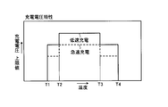
- FIG. 5 is a diagram illustrating the charging current characteristics.
- FIG. 6 is a diagram illustrating the charging voltage characteristics.
- FIG. 7 is a block diagram illustrating an example of an adjustment circuit that adjusts a charging current in the rechargeable cleaner according to the first embodiment.
- FIG. 1 is a perspective view illustrating an example of a rechargeable cleaner according to the first embodiment.
- FIG. 2 is a perspective view illustrating an example of a main body of the rechargeable cleaner according to the first embodiment.
- FIG. 3 is a cross-sectional view
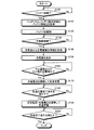
- FIG. 8 is a flowchart illustrating an example of a charging method of the rechargeable cleaner according to the first embodiment, and is a diagram illustrating processing in a main body control circuit.
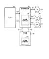
- FIG. 9 is a block diagram illustrating an example of a control circuit of the rechargeable cleaner according to the second embodiment.
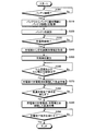
- FIG. 10 is a flowchart illustrating an example of a method of charging the rechargeable cleaner according to the second embodiment, and is a diagram illustrating a process in the main body control circuit.
- FIG. 11 is a flowchart illustrating an example of a charging method of the rechargeable cleaner according to the second embodiment, and is a diagram illustrating processing in a charger control circuit.
- FIG. 12 is a flowchart illustrating an example of a method of charging the rechargeable cleaner according to the second embodiment, and is a diagram illustrating processing in the charger control circuit.
- the X-axis direction is referred to as the “front-back direction”.
- the Y-axis direction is referred to as “left-right direction”.
- the Y-axis direction is a direction that is horizontally orthogonal to the X-axis direction.
- the Z-axis direction is referred to as the “vertical direction”.
- the Z-axis direction is a direction orthogonal to the X-axis direction and the Y-axis direction.
- FIG. 1 is a perspective view illustrating an example of a rechargeable cleaner according to the first embodiment.
- FIG. 2 is a perspective view illustrating an example of a main body of the rechargeable cleaner according to the first embodiment.
- FIG. 3 is a cross-sectional view illustrating an example of a main body of the rechargeable cleaner according to the first embodiment.
- FIG. 4 is a block diagram illustrating an example of a control circuit of the rechargeable cleaner according to the first embodiment.
- the rechargeable cleaner 10 operates by being supplied with power from a rechargeable battery pack (hereinafter, referred to as “battery”) 26.
- battery hereinafter, referred to as “battery”
- the rechargeable cleaner 10 includes a main unit (main unit) 20, a pipe unit 30, a nozzle unit 40, a control circuit board 60, and a charger 100.
- the main unit 20 generates a suction force capable of sucking dust together with air.
- the main unit 20 includes a case 21, an intake port 22, a motor 23, an intake fan 24, a dust filter 25, a battery 26, a handle 27, and a DC (Direct Current) jack 28.
- DC Direct Current
- the case 21 defines the outer shape of the main unit 20.
- the case 21 houses a motor 23, a suction fan 24, a dust filter 25, and a battery 26.
- the case 21 is formed in a cylindrical shape.
- the case 21 is provided with an opening / closing cover 211, a lid 212, and an exhaust port 213.
- the open / close cover 211 forms a part of the outer periphery of the case 21.
- the opening / closing cover 211 is arranged on the upper front part of the outer periphery of the case 21.
- the opening / closing cover 211 opens and closes with respect to the case 21. With the opening / closing cover 211 opened, the dust collection filter 25 can be taken in and out.
- the lid 212 forms a part of the outer periphery of the case 21.
- the lid 212 opens and closes with respect to the case 21. With the cover 212 opened, the battery 26 can be taken in and out.
- the exhaust port 213 connects the outside and the inside of the case 21.
- the exhaust port 213 discharges the air sucked from the suction port 22 to the outside of the case 21.
- the suction port 22 is a suction port that sucks dust into the dust collection filter 25 together with air.
- the suction port 22 communicates between the outside and the inside of the case 21.
- the suction port 22 is arranged at a front end of the case 21.
- the pipe unit 30 can be connected to the suction port 22.
- the suction port 22 sucks external air into the housing 2 through the pipe unit 30 when the suction fan 24 rotates.
- the motor 23 rotates the suction fan 24 for generating a suction force capable of sucking dust together with air by rotating.
- the motor 23 is rotated by electric power supplied from the battery 26 via a discharge path P11 that is an electric wire.
- the motor 23 is connected to a suction fan 24 via an output shaft.
- the motor 23 is disposed inside the case 21 behind the suction port 22, the suction fan 24, and the dust filter 25.
- the rotation speed of the motor 23 may be adjustable. In the present embodiment, the rotation speed of the motor 23 can be adjusted in three stages.
- the rotation speed of the motor 23 is controlled by a discharge current supplied from a main unit control circuit (main unit control unit) 70 of the control circuit board 60.
- the suction fan 24 generates a suction force capable of sucking dust together with air when the motor 23 rotates.
- the suction fan 24 generates an air flow capable of sucking dust together with air.
- the suction fan 24 is disposed inside the case 21 on the front side of the motor 23 and on the rear side of the dust filter 25.
- the suction fan 24 is connected to a rotation shaft of the motor 23.
- the suction fan 24 rotates when the motor 23 rotates.
- air is sucked into the case 21 from the suction port 22.
- the air volume of the suction fan 24 can be adjusted in conjunction with the rotation speed of the motor 23.
- the suction fan 24 can adjust the air volume in three stages.
- the air volume of the suction fan 24 corresponds to the operation mode of the rechargeable cleaner 10.
- the dust collection filter 25 removes dust contained in the sucked air.
- the dust collection filter 25 is formed in a cylindrical shape with one opening and the other end closed.
- the dust collection filter 25 is housed inside the case 21. More specifically, the dust collection filter 25 is disposed inside the case 21 behind the suction port 22.
- the dust collection filter 25 is disposed inside the case 21 in front of the suction fan 24.
- the opening of the dust collection filter 25 faces the suction port 22.
- the dust collection filter 25 allows the air sucked from the suction port 22 to pass therethrough, and keeps dust contained in the air inside.
- the air that has passed through the dust collection filter 25 is discharged from the exhaust port 213.
- the dust collection filter 25 can be mounted and removed with the cover 211 opened.
- the battery 26 is a rechargeable battery.
- the battery 26 is capable of quick charging.
- the battery 26 can be charged at a charging rate of 3C or more and less than 10C.
- Battery 26 supplies electric power to motor 23 of rechargeable cleaner 10.
- the battery 26 is formed by connecting a plurality of cells. In the present embodiment, the capacity of the battery 26 is about 1 Ah or more and about 2 Ah or less.
- the battery 26 is detachable inside the case 21 with the lid 212 opened.
- the battery 26 is electrically connected to the main unit control circuit 70 of the control circuit board 60 via a signal path P12 as a signal line and a charge / discharge path P13 as an electric wire.
- the battery 26 By setting the charging rate to $ 3C or more, the battery 26 is fully charged in 20 minutes or less. If the time is about 20 minutes, the length of the rest time is a typical rest time, so that the battery 26 is charged while the user is taking a rest.
- the charge rate is less than 10 C
- the capacity of the battery 26 is 1 Ah or more and 2 Ah or less
- the on-resistance of an FET (not shown) arranged in the circuit is 1 m ⁇
- the power consumption is 0.1 W or more and 0.4 W or less. Become. With this level of power consumption, the amount of heat generated is small, so a heat sink is not required.
- the battery 26 can detect at least one of the cell temperature and the cell voltage of the battery 26.
- the battery 26 detects a cell temperature and a cell voltage of the battery 26.
- the cell voltage of the battery 26 can be detected by a monitoring circuit (not shown).
- the cell temperature of the battery 26 can be detected by a temperature detection circuit (not shown).
- the battery 26 includes, as an analog signal, battery identification information for identifying the type of the battery 26 and battery information including at least one of the cell temperature and the cell voltage of the battery 26 via a signal path P12. Output to When connected to main unit 20, battery 26 outputs battery identification information and battery information to main unit control circuit 70.
- the battery 26 outputs battery information to the main unit control circuit 70 at a predetermined timing after the start of charging.
- the predetermined timing may be a timing at fixed time intervals or a timing at which the cell voltage or the cell temperature has changed by a threshold value or more.
- the discharge of the battery 26 via the charge / discharge path P13 is controlled by the main body control circuit 70.
- the discharge current flows through the charge / discharge path P13 and the discharge path P11.
- the battery 26 is controlled by the main body control circuit 70 to be charged via the charging path P17 and the charging / discharging path P13 which are electric wires.
- the charging current flows through the charging path P17 and the charging / discharging path P13.
- the handle 27 is a gripping portion that is gripped by the user.
- the DC jack 28 can be electrically connected to the DC plug 104 of the charger 100.
- the DC jack 28 can be electrically connected to the battery 26 via the control circuit board 60.
- the DC jack 28 supplies the charging DC supplied from the charger 100 to the battery 26 via the control circuit board 60.
- the pipe unit 30 allows the air and dust sucked from the nozzle unit 40 to pass through.
- the pipe unit 30 is detachable from the suction port 22 and the nozzle unit 40.
- the pipe unit 30 connects the suction port 22 and the nozzle unit 40.
- the pipe unit 30 has a pipe member 31.
- the pipe member 31 is formed in a cylindrical shape.
- the front end of the pipe member 31 can be connected to the nozzle unit 40.
- the rear end of the pipe member 31 can be connected to the suction port 22.
- the nozzle unit 40 sucks air and dust.
- the nozzle unit 40 is detachable from the front end of the pipe member 31 of the pipe unit 30.
- the nozzle unit 40 has a connecting part 41 and a head part 42.
- the connecting portion 41 can be connected to the front end of the pipe member 31 of the pipe unit 30.
- the connecting portion 41 is formed in a pipe shape.
- the connecting portion 41 is formed in an inverted shape in a side view.
- the connecting portion 41 has a head portion 42 rotatably connected to a distal end portion.
- the head section 42 is a suction port for sucking air and dust.
- the head section 42 has a housing 421 and a suction port (not shown).
- the head part 42 is connected to the connecting part 41 so as to be relatively rotatable in the circumferential direction of the pipe.
- the housing 421 is formed in a box shape extending in the left-right direction.
- the housing 421 can accommodate various members.
- the suction port is an opening formed on the bottom surface of the housing 421. The suction port communicates with the connecting portion 41.
- the operation switch 50 is disposed on the handle 27.
- the operation switch 50 is an electronic switch that can receive various operations on the rechargeable cleaner 10.
- the operation switch 50 can be operated while the user holds the handle 27.
- the operation switch 50 includes a drive switch (mode setting operation unit) 51 and a stop switch 52.
- the drive switch 51 is a switch pressed by the user to switch the operation mode indicating the strength of the suction force of the rechargeable cleaner 10.
- the operation mode can be alternately switched between strong (high mode), standard (low mode), and turbo (high power mode).
- high mode the motor 23 is rotated at a high speed.
- the low mode causes the motor 23 to rotate at a lower speed than the high mode.
- high power mode the motor 23 is rotated at a higher speed than in the high mode.
- the drive switch 51 outputs an electric signal corresponding to the operation information to the main unit control circuit 70 via the signal path P14 which is a signal line.
- the stop switch 52 is a switch pressed by a user to stop the operation of the rechargeable cleaner 10. When the stop switch 52 is pressed during the operation of the rechargeable cleaner 10, the operation can be stopped. When pressed, the stop switch 52 outputs an electric signal corresponding to the operation information to the main unit control circuit 70 via the signal path P15 which is a signal line.
- the LED 54 is arranged in front of the operation switch 50.
- the LED 54 is lit when the rechargeable cleaner 10 is charged to indicate a charged state. For example, the LED 54 lights in red during quick charging, lights in orange during low-speed charging, and turns off when not charging or when fully charged.
- the lighting state of the LED 54 is controlled via the main body control circuit 70.
- the control circuit board 60 is disposed inside the case 21.
- the control circuit board 60 has a function of receiving power from the charger 100 to charge the battery 26 and a function of receiving power from the battery 26 and discharging to the motor 23.
- the control circuit board 60 has a discharge path and a charge path.
- the discharge path is a path through which a current flows from the positive electrode side of the battery 26 to the negative electrode side of the battery 26 via the motor 23, in other words, electric power is discharged from the battery 26.
- the charging path is a path for connecting the positive terminal of the charger 100 to the positive terminal of the battery 26 and connecting the negative terminal of the charger 100 to the negative terminal of the battery 26, in other words, charging the battery 26.
- the control circuit board 60 is provided with electronic components for mounting such functions.
- the control circuit board 60 has a main body control circuit 70.
- the main unit control circuit 70 includes a CPU (Central Processing Unit) that performs arithmetic processing, and a memory that stores a program.
- the main body control circuit 70 executes the rotation of the motor 23 and the charging and discharging of the battery 26 according to the control program stored in the memory.
- CPU Central Processing Unit
- a current value of a discharge current set for each operation mode is stored as control data for rotating the motor 23 in each operation mode.
- the memory of the main unit control circuit 70 stores information indicating the specifications of the charger and the charging capacity for each charger type.
- the memory of the main body control circuit 70 stores, for each battery type, a rated capacity, a range of allowable voltage during charging, a range of allowable temperature during charging, and a high-rate charging current for rapid charging.
- the maximum current is stored as charging information.
- charging current characteristics and charging voltage characteristics are stored as charging information for each battery type.
- FIG. 5 is a diagram illustrating the charging current characteristics.
- FIG. 6 is a diagram illustrating the charging voltage characteristics.
- the charging current characteristic defines an upper limit value of the charging current with respect to the cell temperature.
- the charging current characteristics define the characteristics of the high-rate charging current for rapid charging and the characteristics of the low-rate charging current for low-speed charging, respectively.
- the charging voltage characteristic defines an upper limit value of the charging voltage with respect to the cell temperature.
- the charging voltage characteristic defines a charging voltage characteristic for fast charging and a charging voltage characteristic for low-speed charging, respectively.
- the main unit control circuit 70 is electrically connected to the motor 23 via the discharge path P11.
- the main unit control circuit 70 is electrically connected to the battery 26 via a signal path P12 and a charge / discharge path P13.
- the main unit control circuit 70 is electrically connected to the drive switch 51 via the signal path P14.
- the main unit control circuit 70 is electrically connected to the stop switch 52 via the signal path P15.
- the main unit control circuit 70 is electrically connected to the charger 100 via a signal path P16 and a charging path P17, which are signal lines.
- the main unit control circuit 70 Upon detecting that the battery 26 is connected to the main unit 20, the main unit control circuit 70 acquires battery identification information and battery information from the battery 26 via the signal path P12. The main unit control circuit 70 acquires battery information from the battery 26 via the signal path P12 at a predetermined timing after the start of charging.
- the main unit control circuit 70 detects that the charger 100 is connected to the main unit 20, the main unit control circuit 70 acquires charger identification information from the charger 100 via the signal path P16.
- the main unit control circuit 70 detects an output voltage between a terminal connected to the positive electrode side of the battery 26 and a terminal connected to the negative electrode side.
- the detected output voltage is the voltage of the battery 26, in other words, the output voltage from the battery 26.
- the main body control circuit 70 sets the operation mode as an initial operation mode, for example, a high mode.
- the main unit control circuit 70 supplies the discharge current of the battery 26 to the motor 23 via the charge / discharge path P13 and the discharge path P11.
- the operation mode is switched according to the presence or absence of the operation of the drive switch 51 or the operation continuation time, in other words, the continuation time of the ON state, until the stop switch 52 is operated. As a result, the main body control circuit 70 switches the discharge current of the battery 26.
- the main body control circuit 70 controls the rotation speed of the motor 23 according to the operation mode each time the drive switch 51 is operated during the operation of the motor 23.
- the main body control circuit 70 controls the rotation speed of the motor 23 to be a high speed corresponding to the high mode.
- the main unit control circuit 70 increases the discharge current of the battery 26.
- the main body control circuit 70 controls the rotation speed of the motor 23 to be a normal speed corresponding to the low mode.
- the main unit control circuit 70 reduces the discharge current of the battery 26.
- the main body control circuit 70 controls the rotation speed of the motor 23 to be a high speed corresponding to the high power mode.
- the main unit control circuit 70 makes the discharge current of the battery 26 larger than the discharge current in the high mode.
- the suction amount of the rechargeable cleaner 10 is controlled in accordance with each operation mode.
- the main body control circuit 70 stops supplying the discharge current and stops the rotation of the motor 23.
- the main unit control circuit 70 controls charging of the battery 26.
- the main unit control circuit 70 charges the battery 26 rapidly and then charges it at a low speed.
- the main unit control circuit 70 supplies at least one of the high-rate DC current and voltage output from the charger 100 based on the battery information, the battery identification information, and the charger identification information during charging, to the battery 26. Is adjusted to a charging current and a charging voltage necessary to charge the battery, and then output.
- Rapid charging refers to charging with a high-rate charging current of 3C or more and less than 10C.
- C is a unit representing a charge / discharge rate (charge / discharge rate).
- charge / discharge rate charge / discharge rate
- the current value of the charge current is three times that at 1C
- the current value of the charge current is ten times that at 1C.
- the main body control circuit 70 determines that the charging current is about 3 A or more and about 10 A or less, and when the capacity of the battery 26 is 2 Ah, the charging current is about 6 A or more and about 20 A or less. Is output.
- Low-speed charging refers to charging with a lower charging current than rapid charging.
- Low-speed charging refers to charging with a charging current having a current value equal to or less than the charging current value for quick charging. For example, if the quick charge is a constant current of 10 A, the slow charge is charged at a constant voltage with a current value of less than 10 A.
- the charging control by the main body control circuit 70 will be described in more detail.
- the main unit control circuit 70 starts rapid charging of the battery 26 when the charger 100 is connected to the main unit 20 and the state of the battery 26 satisfies the charging start condition when the driving of the motor 23 is stopped.
- the main unit control circuit 70 acquires a current value of a high-rate charging current in rapid charging based on the charging information and the battery identification information.
- the main body control circuit 70 generates and charges the high-rate charging current of the obtained current value by the adjustment circuit (adjustment circuit unit).
- the charge start condition is that the cell temperature of the battery 26 is equal to or less than the threshold value for charge start determination and the cell voltage is equal to or less than the threshold value for charge start determination.
- the charging start condition is stored as control data in the memory of the main unit control circuit 70.
- the charging start condition may further include a condition that the remaining capacity of the battery 26 is lower than a threshold value for determining the start of charging. More specifically, the fact that the output voltage from the battery 26 is lower than the threshold voltage for charge start determination may be added to the charge start condition.
- FIG. 7 is a block diagram illustrating an example of an adjustment circuit that adjusts a charging current in the rechargeable cleaner according to the first embodiment.
- the adjustment circuit is disposed on the control circuit board 60.
- the adjustment circuit adjusts at least one of a charging current and a charging voltage necessary for charging the battery 26, and outputs the high-output constant voltage output from the charger 100.
- the adjustment circuit converts the output to a low output by the voltage converter 61 as necessary, and outputs the low output.
- the main unit control circuit 70 switches to the low-speed charging during the quick charging when the condition for completing the quick charging is satisfied.
- the condition for completing the quick charge is that the cell voltage of the battery 26 falls within a predetermined range including the threshold voltage, or that the cell temperature falls outside the allowable temperature range.
- the condition for completing the quick charge is stored as control data in the memory of the main unit control circuit 70.
- the quick charge completion condition may be added to the condition that the output voltage from the battery 26 is higher than the threshold voltage for quick charge completion determination.
- the main body control circuit 70 stops charging when the charging completion condition is satisfied during low-speed charging.
- the completion condition of the charging is that the battery 26 is fully charged.
- the charge completion condition is determined based on, for example, at least one of an elapsed time from the start of charging, a charge capacity of the battery 26, and a cell voltage of the battery 26.
- the charging completion condition is stored as control data in the memory of the main body control circuit 70.
- the main unit control circuit 70 monitors various parameters such as the cell voltage, the cell temperature, and whether or not the battery 26 is disconnected in addition to the output voltage from the battery 26. When these parameters are abnormal, charging / discharging of the battery 26 is stopped. The main unit control circuit 70 adjusts the charging current and the charging voltage to appropriate values within a range in which the current value and the voltage value do not exceed the upper limits based on the cell temperature, the charging current characteristic, and the charging voltage characteristic. Output.
- the main body control circuit 70 can detect the temperature of the control circuit board 60 and the input voltage input from the charger 100.
- the main unit control circuit 70 regulates charging of the battery 26 when the temperature of the control circuit board 60 is equal to or higher than the threshold value or when the input voltage is low.
- the charging control of the battery 26 by the main body control circuit 70 is continued until the battery 26 is fully charged.
- the main body control circuit 70 stops supplying the charging current and ends the charging of the battery 26.
- the charger 100 generates and outputs a DC for charging the battery 26 from the AC supplied from the AC power supply.
- Charger 100 has insertion plug 101, adapter case 102, electric wire 103, and DC plug 104.
- the insertion plug 101 can be inserted into an outlet of an AC power supply.
- Various electronic components for generating a direct current are accommodated in the adapter case 102.
- Various electronic components housed in the adapter case 102 electrically connect the insertion plug 101 and the electric wire 103.
- the electric wire 103 electrically connects the insertion plug 101 and the DC plug 104.
- the DC plug 104 is arranged at the tip of the electric wire 103.
- the DC plug 104 can be electrically connected to the DC jack 28 of the main unit 20.
- the DC plug 104 supplies the direct current generated in the charger 100 to the battery 26 via the control circuit board 60 by being inserted into the DC jack 28 of the main unit 20.
- the charger 100 outputs charger identification information for identifying the type of the charger 100 as an analog signal to the main unit control circuit 70 via the signal path P16. When connected to main unit 20, charger 100 outputs charger identification information to main unit control circuit 70.
- FIG. 8 is a flowchart illustrating an example of a charging method of the rechargeable cleaner according to the first embodiment, and is a diagram illustrating processing in a main body control circuit.
- battery 26 When connected to main unit 20, battery 26 outputs battery identification information and battery information to main unit control circuit 70.
- the battery 26 outputs battery information to the main unit control circuit 70 at a predetermined timing after the start of charging.
- charger 100 When connected to main unit 20, charger 100 outputs charger identification information to main unit control circuit 70.
- the main unit control circuit 70 determines whether the battery 26 is connected to the main unit 20 (step S100). When determining that battery 26 is connected (Yes in step S100), main body control circuit 70 proceeds to step S110. When determining that battery 26 is not connected (No in step S100), main body control circuit 70 executes the process of step S100 again.
- the main unit control circuit 70 acquires the battery identification information and the battery information of the battery 26 from the battery 26 via the signal path P12 (step S110).
- the battery 26 outputs the battery information to the main unit control circuit 70 at a predetermined timing, and the main unit control circuit 70 acquires the battery information.
- the main unit control circuit 70 identifies the battery 26 based on the battery identification information of the battery 26 (step S120).
- the main unit control circuit 70 determines whether the charger 100 is connected to the main unit 20 (step S130). When determining that charger 100 is connected (Yes in step S130), main body control circuit 70 proceeds to step S140. When the DC plug 104 of the charger 100 is connected to the DC jack 28 of the main unit 20, the main unit control circuit 70 determines that the charger 100 is connected. When determining that charger 100 is not connected (No in step S130), main body control circuit 70 executes the process of step S130 again.
- the main unit control circuit 70 acquires charger identification information from the charger 100 (step S140).
- the main unit control circuit 70 identifies the charger 100 based on the charger identification information of the charger 100 (step S150).
- the main unit control circuit 70 determines whether the cell temperature and the cell voltage are equal to or lower than the threshold for charging, based on the battery information, as the charging starting condition (step S160). When it is determined that the cell temperature is equal to or less than the charge start threshold and the cell voltage is equal to or less than the charge start threshold (Yes in step S160), the main body control circuit 70 proceeds to step S170. When determining that the cell temperature is higher than the charging start threshold or that the cell voltage is higher than the charging start threshold (No in step S160), the main body control circuit 70 executes the processing of step S160 again.
- step S160 the main body control circuit 70 may determine that the remaining capacity of the battery 26 is lower than the threshold for determining the start of charging, in addition to the charging start condition.
- the main unit control circuit 70 executes the rapid charging by adjusting the charging current in the adjustment circuit (step S170). More specifically, the main unit control circuit 70 acquires a current value of a high-rate charging current for rapidly charging the battery 26 based on the charging information, the battery identification information, the charger information, and the charger identification information. Further, the main unit control circuit 70 may acquire the current value of the high-rate charging current for rapid charging based on the charging current characteristics and the charging voltage characteristics with respect to the cell temperature stored in advance. The main body control circuit 70 uses the adjustment circuit to generate a high-rate charging current of the obtained current value. Then, the main unit control circuit 70 outputs the generated high-rate charging current to the battery 26 via the charging / discharging path P13.
- step S170 the main body control circuit 70 constantly monitors whether the cell temperature is within the allowable temperature range for charging based on the battery information during rapid charging.
- the main unit control circuit 70 determines whether or not the quick charging completion condition is satisfied based on the battery information (step S180).
- the main unit control circuit 70 may determine whether the cell voltage of the battery 26 is equal to or less than a threshold as a condition for completing the quick charge.
- a threshold as a condition for completing the quick charge.
- step S180 when the cell temperature becomes high during the constant current charging in the rapid charging, the charging current is reduced to switch to the low-speed charging of the constant voltage charging with the constant voltage.
- the constant voltage may be changed linearly or stepwise so as to decrease as the cell temperature increases.
- step S180 the main unit control circuit 70 may determine that the output voltage from the battery 26 is higher than the threshold voltage for quick charge completion determination in addition to the quick charge completion condition.
- the main unit control circuit 70 executes low-speed charging by adjusting the charging current in the adjustment circuit (step S190).
- the main body control circuit 70 constantly monitors the cell temperature and the cell voltage during low-speed charging.
- the main unit control circuit 70 may acquire the current value of the low-rate charging current based on the charging current characteristics and the charging voltage characteristics.
- the main body control circuit 70 decreases the current value of the charging current.
- the main body control circuit 70 stops the low-speed charging.
- the main body control circuit 70 decreases the current value of the charging current.
- the main body control circuit 70 stops the low-speed charging when the cell voltage is higher than the upper threshold and is abnormal.
- the main unit control circuit 70 uses the adjustment circuit to generate a low-rate charging current that is lower than the high rate of the calculated current value. Then, the main unit control circuit 70 outputs the generated low-rate charging current to the battery 26 via the charging / discharging path P13.
- the main unit control circuit 70 determines whether the charging completion condition is satisfied based on the battery information (step S200).
- the main unit control circuit 70 determines a charging completion condition based on the information regarding the charging capacity of the battery 26. For example, the main unit control circuit 70 determines the charging completion condition based on at least one of the elapsed time from the start of charging, the charging capacity of the battery 26, and the cell voltage of the battery 26.
- main body control circuit 70 ends the charging.
- main body control circuit 70 executes the process of step S200 again.
- step S180 or step S200 the main body control circuit 70 determines that the cell temperature has greatly deviated from the allowable temperature range and has reached the preset abnormal temperature, and the charging is stopped. Stop.
- the main unit control circuit 70 sets the high level.
- the charging current at the rate is generated, and the battery 26 is rapidly charged.
- the mode is switched to the low-speed charging.
- the battery 26 is charged at low speed until a charging current at a lower rate than that at the time of rapid charging is generated and the battery is fully charged. Battery 26 is charged to a fully charged state in a short time.
- the main unit control circuit 70 generates a high-rate charging current during fast charging, and generates a lower-rate charging current during low-speed charging than during rapid charging.
- rapid charging can be performed with a high-rate charging current.
- the battery can be charged to a full charge state at a low charge rate with a low charge rate. In this manner, in the present embodiment, the battery 26 can be fully charged in a short time.
- rapid charging is performed with a high-rate charging current of 3 C or more and less than 10 C.
- the thickness of the electric wire in the charging / discharging path can be reduced as compared with the case where a charging current of 10 C or more is used. According to the present embodiment, it is possible to reduce the size and weight.
- the battery 26 since the charging rate is 3 C or more, the battery 26 is fully charged in 20 minutes or less. According to the present embodiment, the battery 26 can be charged during a general rest period.
- the power consumption when the charge rate is less than 10 C, the capacity of the battery 26 is 1 Ah or more and 2 Ah or less, and the on-resistance of an unillustrated FET arranged in the circuit is 1 m ⁇ , the power consumption is 0.1 W or more. 0.4 W or less. As described above, according to the present embodiment, power consumption is suppressed and a heat radiating plate is not required, so that the size and the weight can be reduced.
- the memory of the main unit control circuit 70 stores charging information for each battery type and charger information for each charger type.
- a current value of a high-rate charging current in rapid charging is acquired based on charging information and battery identification information, charger information and charger identification information.
- rapid charging can be appropriately performed regardless of the type of the battery 26 and the type of the charger 100.
- FIG. 9 is a block diagram illustrating an example of a control circuit of the rechargeable cleaner according to the second embodiment.
- FIG. 10 is a flowchart illustrating an example of a method of charging the rechargeable cleaner according to the second embodiment, and is a diagram illustrating a process in the main body control circuit.
- FIG. 11 is a flowchart illustrating an example of a charging method of the rechargeable cleaner according to the second embodiment, and is a diagram illustrating processing in a charger control circuit.
- FIG. 12 is a flowchart illustrating an example of a method of charging the rechargeable cleaner according to the second embodiment, and is a diagram illustrating processing in the charger control circuit.
- the basic structure of the rechargeable cleaner 10 is the same as that of the rechargeable cleaner 10 of the first embodiment.
- the same components as those of the rechargeable cleaner 10 are denoted by the same reference numerals or corresponding reference numerals, and detailed description thereof will be omitted.
- This embodiment is different from the first embodiment in that the main unit control circuit 70 does not have an adjustment circuit.
- the main body control circuit 70 supplies a charger control circuit (charger control unit) 110 with at least one of a charging current and a charging voltage necessary for charging the battery 26.
- a control signal for current adjustment is output so as to be adjusted and output.
- the main body control circuit 70 outputs a control signal for current adjustment based on the cell temperature, the charging current characteristic, and the charging voltage characteristic, in a range where the current value and the voltage value do not exceed the upper limit values.
- the main unit control circuit 70 does not have an adjustment circuit.
- the control signal for current adjustment includes at least one of a current value of a charging current generated and output in the charger 100 and a voltage value of a charging voltage.
- the charger 100 has a charger control circuit 110 in addition to the plug 101, the adapter case 102, the electric wire 103, and the DC plug 104.
- the charger control circuit 110 includes a CPU that performs arithmetic processing and a memory that stores a program. The charger control circuit 110 adjusts and outputs at least one of the current value of the charging current and the voltage value of the charging voltage based on the current adjustment control signal from the main body control circuit 70.
- steps S300 to S360, S380, and S400 are the same as those in steps S100 to S160, S180, and S200 in the flowchart shown in FIG.
- the main unit control circuit 70 adjusts the charging current in the charger 100 to execute rapid charging (step S370). More specifically, the main unit control circuit 70 acquires a current value of a high-rate charging current for rapidly charging the battery 26 based on the charging information, the battery identification information, the charger information, and the charger identification information. Further, the main unit control circuit 70 may acquire the current value of the high-rate charging current for rapid charging based on the charging current characteristics and the charging voltage characteristics with respect to the cell temperature stored in advance. The main unit control circuit 70 outputs a control signal for current adjustment to the charger 100 so as to generate a high-rate charging current of the obtained current value. Then, main unit control circuit 70 outputs the high-rate charging current generated by charger 100 to battery 26 via charging / discharging path P13.
- the main unit control circuit 70 adjusts the charging current in the charger 100 and executes low-speed charging (step S390).
- the main unit control circuit 70 may acquire the current value of the low-rate charging current based on the charging current characteristics and the charging voltage characteristics.
- the main unit control circuit 70 outputs a control signal for current adjustment to the charger 100 so as to generate a low-rate charging current lower than the high rate of the calculated current value.
- main unit control circuit 70 outputs the low-rate charging current generated by charger 100 to battery 26 via charging / discharging path P13.
- the charger control circuit 110 determines whether the charger 100 is connected to the main unit 20 (step S500). When determining that charger 100 is connected (Yes in step S500), charger control circuit 110 proceeds to step S510. When the DC plug 104 of the charger 100 is connected to the DC jack 28 of the main unit 20, the charger control circuit 110 determines that the DC plug is connected to the main unit 20. If the charger control circuit 110 does not determine that it is connected to the main unit 20 (No in step S500), it executes the process of step S500 again.
- the charger control circuit 110 outputs the charger identification information of the charger 100 to the main unit control circuit 70 via the signal path P12 (Step S510).
- the charger control circuit 110 determines whether or not a current adjustment control signal for adjusting the charging current has been received from the main body control circuit 70 (step S600). When determining that the control signal for the current adjustment has been received (Yes in step S600), charger control circuit 110 proceeds to step S610. If it is not determined that the control signal for current adjustment has been received (No in step S600), charger control circuit 110 executes the process of step S600 again.
- the charger control circuit 110 adjusts the charging current based on the current adjustment control signal (step S610).
- the charger control circuit 110 outputs the adjusted charging current to the main unit control circuit 70 (step S620).
- the main unit control circuit 70 causes the charger 100 to generate and output a high-rate charging current during rapid charging, and to generate and output a lower-rate charging current than during rapid charging during low-speed charging.
- rapid charging can be performed with a high-rate charging current.
- the electronic components for performing the current adjustment by the charger 100 and controlling the charging current and the charging voltage are not arranged on the control circuit board 60.
- the main unit 20 can be reduced in size and weight.
- the present embodiment can reduce the burden on the user when using the rechargeable cleaner 10.
- the electronic components for controlling the charging current and the charging voltage are not arranged on the control circuit board 60 by adjusting the current with the charger 100.
- the number of electronic components that generate heat in the main unit 20 can be suppressed.
- various members arranged in the main unit 20 can have a long life.
- the electric wire 103 of the charger 100 may be detachable from the adapter case 102. Thereby, when the electric wire 103 is disconnected, it can be easily replaced. Also, the electric wire 103 can be replaced with an electric wire 103 having an appropriate length according to the place where the charger 100 is used.
- the main unit 20 may be provided with a USB terminal capable of supplying power from the battery 26 to an external electronic device.
- a USB terminal capable of supplying power from the battery 26 to an external electronic device.
- the battery 26 may be capable of detecting the voltage of the battery 26.
- the voltage of the battery 26 can be detected by a monitoring circuit (not shown) arranged inside the battery 26.
- the monitoring circuit detects that the voltage of the battery 26 has exceeded the threshold value, the monitoring circuit can output the detection information to the main unit control circuit 70 as a digital signal.
- the main unit control circuit 70 can acquire the voltage detected in the battery 26.
- the main body control circuit 70 can calculate the voltage drop in the charge / discharge path P13 by comparing the voltage detected in the battery 26 with the voltage of the battery 26 detected in the main body control circuit 70. Become. This suppresses erroneous recognition of the voltage of the battery 26. In this way, charging can be more appropriately controlled.
- the battery 26 and the main body control circuit 70 are electrically connected via the signal path P12 which is a signal line and the charge / discharge path P13 which is an electric wire. It may function as a signal path P12 in addition to the path P13. For example, when charging / discharging is stopped by the switch, the electric wire may function as the signal path P12. Alternatively, information may be made communicable, for example, using an inductance component in the cell.
- the configuration of the rechargeable cleaner 10 described above is an example.
- the combination of the main unit 20, the pipe unit 30, and the nozzle unit 40 and their respective shapes are not limited thereto.
- the battery 26 may be detachable inside or outside the case 21 or may be non-removably assembled.
Landscapes
- Engineering & Computer Science (AREA)
- Power Engineering (AREA)
- General Chemical & Material Sciences (AREA)
- Chemical & Material Sciences (AREA)
- Chemical Kinetics & Catalysis (AREA)
- Electrochemistry (AREA)
- Manufacturing & Machinery (AREA)
- Mechanical Engineering (AREA)
- Physics & Mathematics (AREA)
- General Physics & Mathematics (AREA)
- Robotics (AREA)
- Charge And Discharge Circuits For Batteries Or The Like (AREA)
- Secondary Cells (AREA)
- Electric Vacuum Cleaner (AREA)
Abstract
モータ23によって空気とともに塵埃を吸込可能な吸込力を生じさせる本体ユニットと、モータ23に電力を供給する充電式のバッテリ26と、バッテリ26を充電する充電器100と、本体ユニットに配置された本体部制御回路70と、を備え、本体部制御回路70は、バッテリ26から取得したセル電圧を示すセル電圧情報と、セル温度を示すセル温度情報と、バッテリ26を識別するバッテリ識別情報と、充電器100から取得した充電器100を識別する充電器識別情報とに基づいて、充電電流と充電電圧との少なくともどちらかを制御する。
Description
本発明は、充電式クリーナに関する。
従来の充電式クリーナは、バッテリが完全放電状態から満充電状態になるまで充電するには、数時間を要する。そこで、短時間で、満充電状態にすることが可能な充電式クリーナに関する技術が知られている(例えば、特許文献1参照)。特許文献1は、バッテリとして、10C以上の電流で急速充電できるリチウムイオン二次電池が用いられることを特徴としている。
10C以上の充電レートで充電する場合、充電電流の電流値が、1Cの充電レートの充電電流の電流値の10倍以上になる。充電電流の電流値が大きくなると、充電経路に使用する電線を通常の電線より太くする必要があるので、充電式クリーナと充電器とが大型化、重量化するおそれがある。また、充電電流の電流値が大きくなると、急速充電時に、電子部品が発熱して高温になるおそれがあり、各種部材の寿命に影響を与えるおそれがある。または、その発熱を効率よく放熱するために、大きな放熱器を取り付けるため、充電式クリーナと充電器とが、大型化、重量化するおそれもある。そこで、小型かつ軽量で、各種部材の寿命への影響が低減された急速充電可能な充電式クリーナが望まれている。
本発明の態様は、小型かつ軽量で、各種部材の寿命への影響が低減された急速充電可能な充電式クリーナを提供することを目的とする。
本発明の態様に従えば、モータによって空気とともに塵埃を吸込可能な吸込力を生じさせる本体部と、前記モータに電力を供給する充電式のバッテリと、前記バッテリを充電する充電器と、前記本体部に配置された本体部制御部と、を備え、前記本体部制御部は、前記バッテリから取得したセル電圧を示すセル電圧情報と、セル温度を示すセル温度情報と、前記バッテリを識別するバッテリ識別情報と、前記充電器から取得した前記充電器を識別する充電器識別情報とに基づいて、充電電流と充電電圧との少なくともどちらかを制御する、ことを特徴とする充電式クリーナが提供される。
本発明の態様によれば、小型かつ軽量で、各種部材の寿命への影響が低減された急速充電可能な充電式クリーナが提供される。
以下、本発明の実施形態について、添付図面を参照して詳細に説明する。なお、この実施形態によりこの発明が限定されるものではない。また、下記実施形態における構成要素には、当業者が置換可能かつ容易なもの、または実質的に同一のものを含む。さらに、以下に記載した構成要素は適宜組み合わせることが可能であり、また、実施形態が複数ある場合には、各実施形態を組み合わせることも可能である。
以下の説明においては、X軸方向を、「前後方向」とする。Y軸方向を、「左右方向」とする。Y軸方向とは、X軸方向に対して水平に直交する方向である。前後方向「前」側へ向かって、左手側が「左」、右手側が「右」である。Z軸方向を、「上下方向」とする。Z軸方向とは、X軸方向及びY軸方向に対して直交する方向である。
[第一実施形態]
図1ないし図4を参照して、充電式クリーナ10の概要について説明する。図1は、第一実施形態に係る充電式クリーナの一例を示す斜視図である。図2は、第一実施形態に係る充電式クリーナの本体部の一例を示す斜視図である。図3は、第一実施形態に係る充電式クリーナの本体部の一例を示す断面図である。図4は、第一実施形態に係る充電式クリーナの制御回路の一例を示すブロック図である。充電式クリーナ10は、充電式のバッテリパック(以下、「バッテリ」という。)26から電力が供給されて動作する。
図1ないし図4を参照して、充電式クリーナ10の概要について説明する。図1は、第一実施形態に係る充電式クリーナの一例を示す斜視図である。図2は、第一実施形態に係る充電式クリーナの本体部の一例を示す斜視図である。図3は、第一実施形態に係る充電式クリーナの本体部の一例を示す断面図である。図4は、第一実施形態に係る充電式クリーナの制御回路の一例を示すブロック図である。充電式クリーナ10は、充電式のバッテリパック(以下、「バッテリ」という。)26から電力が供給されて動作する。
充電式クリーナ10は、本体ユニット(本体部)20と、パイプユニット30と、ノズルユニット40と、制御回路基板60と、充電器100とを備える。
本体ユニット20は、空気とともに塵埃を吸込可能な吸込力を生じさせる。本体ユニット20は、ケース21と、吸込口22と、モータ23と、吸込用ファン24と、集塵フィルタ25と、バッテリ26と、ハンドル27と、DC(Direct Current)ジャック28とを有する。
ケース21は、本体ユニット20の外形を規定する。ケース21は、モータ23と、吸込用ファン24と、集塵フィルタ25と、バッテリ26とを収容する。ケース21は、筒状に形成されている。ケース21は、開閉カバー211と、蓋部212と、排気口213とが配置されている。
開閉カバー211は、ケース21の外周の一部を形成している。開閉カバー211は、ケース21の外周の前上部に配置されている。開閉カバー211は、ケース21に対して開閉する。開閉カバー211を開いた状態で、集塵フィルタ25が出し入れ可能になる。
蓋部212は、ケース21の外周の一部を形成している。蓋部212は、ケース21に対して開閉する。蓋部212を開いた状態で、バッテリ26が出し入れ可能になる。
排気口213は、ケース21の外部と内部とを連通する。排気口213は、吸込口22から吸い込んだ空気をケース21の外部へ排出する。
吸込口22は、空気とともに塵埃を集塵フィルタ25へ吸い込む吸込み口である。吸込口22は、ケース21の外部と内部とを連通する。吸込口22は、ケース21の前端部に配置されている。吸込口22は、パイプユニット30が連結可能である。吸込口22は、吸込用ファン24が回転することにより、パイプユニット30を介して外部の空気を筐体2の内部に吸い込む。
モータ23は、回転することによって空気とともに塵埃を吸込可能な吸込力を生じさせるための吸込用ファン24を回転させる。モータ23は、電線である放電経路P11を介してバッテリ26から供給される電力によって回転する。モータ23は、出力軸を介して吸込用ファン24と連結されている。モータ23は、ケース21の内部において、吸込口22と吸込用ファン24と集塵フィルタ25より後側に配置されている。モータ23は、回転速度を調節可能であってもよい。本実施形態では、モータ23は、3段階で回転速度を調節可能である。モータ23は、制御回路基板60の本体部制御回路(本体部制御部)70から供給される放電電流によって回転速度が制御される。
吸込用ファン24は、モータ23が回転することによって空気とともに塵埃を吸込可能な吸込力を生じさせる。吸込用ファン24は、空気とともに塵埃を吸込可能な空気の流れを生じさせる。吸込用ファン24は、ケース21の内部において、モータ23より前側で、集塵フィルタ25より後側に配置されている。吸込用ファン24は、モータ23の回転軸と連結されている。吸込用ファン24は、モータ23が回転すると回転する。吸込用ファン24が回転すると、空気が吸込口22からケース21の内部に吸引される。吸込用ファン24は、モータ23の回転速度に連動して風量が調節可能である。本実施形態では、吸込用ファン24は、3段階で風量を調節可能である。吸込用ファン24の風量は、充電式クリーナ10の動作モードに対応する。
集塵フィルタ25は、吸引した空気に含まれる塵埃を除去する。集塵フィルタ25は、一方が開口し、他方の端部が閉じた筒状に形成されている。集塵フィルタ25は、ケース21の内部に収容されている。より詳しくは、集塵フィルタ25は、ケース21の内部において、吸込口22の後側に配置されている。集塵フィルタ25は、ケース21の内部において、吸込用ファン24の前側に配置されている。集塵フィルタ25は、開口が吸込口22に向かい合っている。集塵フィルタ25は、吸込口22から吸引した空気を通過させ、空気に含まれる塵埃を内部に留めおく。集塵フィルタ25を通過した空気は、排気口213から排出される。集塵フィルタ25は、開閉カバー211を開いた状態で装着と取外しとが可能である。
バッテリ26は、充電式のバッテリである。バッテリ26は、急速充電が可能である。バッテリ26は、3C以上、10C未満の充電レートで充電可能である。バッテリ26は、充電式クリーナ10のモータ23に電力を供給する。バッテリ26は、複数のセルが接続されて形成されている。本実施形態では、バッテリ26の容量は、1Ah程度以上、2Ah程度以下とする。バッテリ26は、蓋部212を開いた状態で、ケース21の内部に着脱可能である。バッテリ26は、制御回路基板60の本体部制御回路70と、信号線である信号経路P12及び電線である充放電経路P13を介して電気的に接続されている。
3C以上の充電レートとすることで、20分以下でバッテリ26が満充電状態になる。20分程度であれば、一般的な休憩時間の長さであるので、ユーザが休憩している間に、バッテリ26が充電される。
10C未満の充電レートとすることで、バッテリ26の容量を1Ah以上、2Ah以下、回路に配置された図示しないFETのオン抵抗を1mΩとすると、消費電力は0.1W以上、0.4W以下となる。この程度の消費電力であれば、発熱量が小さいので、放熱板は不要である。
バッテリ26は、バッテリ26のセル温度とセル電圧との少なくともどちらかを検出可能である。本実施形態では、バッテリ26は、バッテリ26のセル温度とセル電圧とを検出する。バッテリ26のセル電圧は、図示しない監視回路によって検出可能である。バッテリ26のセル温度は、図示しない温度検出回路によって検出可能である。バッテリ26は、バッテリ26の種類を識別するバッテリ識別情報と、バッテリ26のセル温度とセル電圧との少なくともどちらかを含むバッテリ情報とをアナログ信号で、信号経路P12を介して本体部制御回路70に出力する。バッテリ26は、本体ユニット20に接続されたとき、バッテリ識別情報とバッテリ情報とを本体部制御回路70に出力する。バッテリ26は、充電開始後においては所定のタイミングで、バッテリ情報を本体部制御回路70に出力する。
所定のタイミングとは、一定時間間隔ごとのタイミング、または、セル電圧またはセル温度が閾値以上、変化したタイミングとしてもよい。
バッテリ26は、本体部制御回路70によって、充放電経路P13を介する放電が制御される。バッテリ26の放電時、放電電流は、充放電経路P13と放電経路P11とを流れる。
バッテリ26は、本体部制御回路70によって、電線である充電経路P17と充放電経路P13とを介する充電が制御される。バッテリ26の充電時、充電電流は、充電経路P17と充放電経路P13とを流れる。
ハンドル27は、ユーザが把持する把持部である。
DCジャック28は、充電器100のDCプラグ104と電気的に接続可能である。DCジャック28は、制御回路基板60を介してバッテリ26と電気的に接続可能である。これらにより、DCジャック28は、充電器100から供給される充電用の直流を、制御回路基板60を介してバッテリ26へ供給する。
パイプユニット30は、ノズルユニット40から吸引した空気と塵埃とを通過させる。パイプユニット30は、吸込口22とノズルユニット40と着脱可能である。パイプユニット30は、吸込口22とノズルユニット40とを連結する。パイプユニット30は、パイプ部材31を有する。パイプ部材31は、円筒状に形成されている。パイプ部材31は、前端部がノズルユニット40に連結可能である。パイプ部材31は、後端部が吸込口22に連結可能である。
ノズルユニット40は、空気を塵埃とを吸引する。ノズルユニット40は、パイプユニット30のパイプ部材31の前端部に着脱可能である。ノズルユニット40は、連結部41と、ヘッド部42とを有する。
連結部41は、パイプユニット30のパイプ部材31の前端部に連結可能である。連結部41は、パイプ状に形成されている。連結部41は、側面視においてへの字型に形成されている。連結部41は、先端部にヘッド部42が回動可能に連結されている。
ヘッド部42は、空気と塵埃とを吸引する吸込口である。ヘッド部42は、ハウジング421と、図示しない吸込口とを有する。ヘッド部42は、連結部41に対してパイプの周方向で相対的に回転可能に連結される。ハウジング421は、左右方向に延びる箱状に形成されている。ハウジング421は、各種部材を収容可能である。吸込口は、ハウジング421の底面に形成された開口である。吸込口は、連結部41と連通している。
操作スイッチ50は、ハンドル27に配置されている。操作スイッチ50は、充電式クリーナ10に対する各種操作を受付可能な電子スイッチである。操作スイッチ50は、ユーザがハンドル27を握った状態で操作可能である。操作スイッチ50は、駆動スイッチ(モード設定操作部)51と、停止スイッチ52とを有する。
駆動スイッチ51は、充電式クリーナ10の吸込力の強さを示す動作モードを切り替えるためにユーザによって押し操作されるスイッチである。本実施形態では、駆動スイッチ51は、押下されるたびに、動作モードを強(ハイモード)と、標準(ローモード)と、ターボ(ハイパワーモード)とに交互に切り替え可能である。ハイモードは、モータ23を高速で回転させる。ローモードは、モータ23をハイモードより低速で回転させる。ハイパワーモードは、モータ23をハイモードより高速で回転させる。駆動スイッチ51は、押下されるたびに、操作情報に応じた電気信号を信号線である信号経路P14を介して本体部制御回路70に出力する。
停止スイッチ52は、充電式クリーナ10の動作を停止させるためにユーザによって押し操作されるスイッチである。停止スイッチ52は、充電式クリーナ10の動作時に押下されると、動作を停止可能である。停止スイッチ52は、押下されると、操作情報に応じた電気信号を信号線である信号経路P15を介して本体部制御回路70に出力する。
LED54は、操作スイッチ50の前側に配置されている。LED54は、充電式クリーナ10の充電時に点灯して充電状態を示す。例えば、LED54は、急速充電時は赤色で点灯し、低速充電時は橙色で点灯し、充電していない時または満充電時には消灯する。LED54は、本体部制御回路70を介して点灯状態が制御される。
制御回路基板60は、ケース21の内部に配置されている。制御回路基板60は、充電器100から電力供給を受けてバッテリ26を充電する機能と、バッテリ26から電力供給を受けてモータ23へ放電する機能とを有する。言い換えると、制御回路基板60は、放電経路と充電経路とを有する。放電経路は、バッテリ26の正極側からモータ23を介してバッテリ26の負極側へ電流を流す、言い換えると、バッテリ26から電力を放電する経路である。充電経路は、充電器100の正極側端子をバッテリ26の正極側に接続し、充電器100の負極側端子をバッテリ26の負極側に接続する、言い換えると、バッテリ26を充電する経路である。制御回路基板60は、このような機能を実装するための電子部品が組み付けられている。制御回路基板60は、本体部制御回路70を有する。
本体部制御回路70は、演算処理を行うCPU(Central Processing Unit)と、プログラムを格納したメモリとを備える。本体部制御回路70は、メモリに記憶した制御プログラムに従って、モータ23の回転とバッテリ26の充放電とを実行する。
本体部制御回路70のメモリには、各動作モードでモータ23を回転するための制御データとして、動作モードごとに設定された放電電流の電流値が記憶されている。
本体部制御回路70のメモリには、充電器種類ごとの充電器の仕様、充電能力を示す情報が記憶されている。
本体部制御回路70のメモリには、バッテリ種類ごとに、定格容量と、充電時の許容電圧の範囲と、充電時の許容温度の範囲と、急速充電の高レートの充電電流、言い換えると、許容最大電流とが充電情報として記憶されている。また、本体部制御回路70のメモリには、バッテリ種類ごとに、充電電流特性及び充電電圧特性が充電情報として記憶されている。
図5、図6を用いて、充電電流特性及び充電電圧特性について説明する。図5は、充電電流特性を説明する図である。図6は、充電電圧特性を説明する図である。充電電流特性は、セル温度に対して充電電流の上限値を規定している。充電電流特性は、急速充電の高レートの充電電流の特性と、低速充電の低レートの充電電流の特性とをそれぞれ規定している。充電電圧特性は、セル温度に対して充電電圧の上限値を規定している。充電電圧特性は、急速充電の充電電圧の特性と、低速充電の充電電圧の特性とをそれぞれ規定している。
本体部制御回路70は、放電経路P11を介してモータ23と電気的に接続されている。本体部制御回路70は、信号経路P12及び充放電経路P13を介してバッテリ26と電気的に接続されている。本体部制御回路70は、信号経路P14を介して駆動スイッチ51と電気的に接続されている。本体部制御回路70は、信号経路P15を介して停止スイッチ52と電気的に接続されている。本体部制御回路70は、信号線である信号経路P16及び充電経路P17を介して充電器100と電気的に接続されている。
本体部制御回路70は、本体ユニット20にバッテリ26が接続されたことを検出すると、信号経路P12を介して、バッテリ26からバッテリ識別情報とバッテリ情報とを取得する。本体部制御回路70は、充電開始後においては所定のタイミングで、信号経路P12を介して、バッテリ26からバッテリ情報を取得する。
本体部制御回路70は、本体ユニット20に充電器100が接続されたことを検出すると、信号経路P16を介して、充電器100から充電器識別情報を取得する。
本体部制御回路70は、バッテリ26の正極側に接続された端子と、負極側に接続された端子との間の出力電圧を検出する。検出された出力電圧は、バッテリ26の電圧、言い換えると、バッテリ26からの出力電圧である。
本体部制御回路70は、モータ23の停止時に駆動スイッチ51が操作されると、動作モードを、初期動作モードとして、例えばハイモードに設定する。本体部制御回路70は、バッテリ26の放電電流を、充放電経路P13と放電経路P11とを介してモータ23に供給する。そして、初期動作モードの設定後は、停止スイッチ52が操作されるまで、駆動スイッチ51の操作の有無、または、操作継続時間、言い換えると、オン状態の継続時間に応じて動作モードを切り替える。これにより、本体部制御回路70は、バッテリ26の放電電流を切り替える。
本体部制御回路70は、モータ23の動作時に駆動スイッチ51が操作されるたびに、モータ23の回転速度を動作モードに応じて制御する。本体部制御回路70は、駆動スイッチ51が操作されてハイモードにされると、モータ23の回転速度をハイモードに応じた速い速度になるように制御する。本体部制御回路70は、バッテリ26の放電電流を大きくする。本体部制御回路70は、駆動スイッチ51が操作されてローモードにされると、モータ23の回転速度をローモードに応じた通常の速度になるように制御する。本体部制御回路70は、バッテリ26の放電電流を小さくする。本体部制御回路70は、駆動スイッチ51が操作されてハイパワーモードにされると、モータ23の回転速度をハイパワーモードに応じた速い速度になるように制御する。本体部制御回路70は、バッテリ26の放電電流を、ハイモードの放電電流より大きくする。これらにより、充電式クリーナ10の吸引量が、各動作モードに対応して制御される。
本体部制御回路70は、モータ23の回転時に停止スイッチ52が操作されると、放電電流の供給を停止して、モータ23の回転を停止する。
本体部制御回路70は、バッテリ26への充電を制御する。本体部制御回路70は、バッテリ26を急速充電した後、低速充電する。本体部制御回路70は、充電時、バッテリ情報とバッテリ識別情報と充電器識別情報とに基づいて、充電器100から出力された高レートの直流の電流と電圧との少なくともどちらかを、バッテリ26を充電するのに必要な充電電流と充電電圧とに調整して出力する。
急速充電は、3C以上、10C未満の高レートの充電電流による充電のことである。「C」は、充放電率(充放電レート)を表す単位である。完全放電状態から満充電状態まで、定電流充電をした際に、1時間で達成可能であることを1Cという。1/3時間で達成可能であることを3C、1/10時間で達成可能であることを10Cという。3Cの充放電率では、充電電流の電流値は1Cのときの3倍、10Cの充放電率では、充電電流の電流値は1Cのときの10倍である。
本体部制御回路70は、急速充電時は、例えば、バッテリ26の容量が1Ahとすると、3A程度以上、10A程度以下、バッテリ26の容量が2Ahとすると、6A程度以上、20A程度以下の充電電流を出力する。
低速充電は、急速充電より低レートの充電電流による充電のことである。低速充電は、急速充電の充電電流の電流値以下の電流値の充電電流による充電のことである。例えば、急速充電が10Aの一定電流である場合、低速充電は10A未満の電流値で一定電圧で充電される。
本体部制御回路70による充電制御についてより詳しく説明する。本体部制御回路70は、モータ23の駆動停止時、充電器100が本体ユニット20に接続されて、バッテリ26の状態が充電開始条件を満たすと、バッテリ26への急速充電を開始する。本体部制御回路70は、充電情報とバッテリ識別情報とに基づいて、急速充電における高レートの充電電流の電流値を取得する。本体部制御回路70は、取得した電流値の高レートの充電電流を調整回路(調整回路部)によって生成して充電する。
充電開始条件とは、バッテリ26のセル温度が充電開始判定用の閾値以下、かつ、セル電圧が充電開始判定用の閾値以下であることである。充電開始条件は、本体部制御回路70のメモリに制御データとして記憶されている。
さらに、充電開始条件は、バッテリ26の残容量が充電開始判定用の閾値より低いことを条件に加えてもよい。より詳しくは、バッテリ26からの出力電圧が充電開始判定用の閾値電圧より低いことを、充電開始条件に加えてもよい。
図7を用いて、調整回路について説明する。図7は、第一実施形態に係る充電式クリーナにおいて充電電流を調整する調整回路の一例を示すブロック図である。調整回路は、制御回路基板60に配置されている。調整回路は、充電器100から出力される高出力の一定電圧を、バッテリ26を充電するのに必要な充電電流と充電電圧との少なくともどちらかを調整して出力する。調整回路は、必要に応じて電圧変換器61によって、低出力に変換して出力する。
本体部制御回路70は、急速充電中、急速充電の完了条件を満たすと、低速充電に切り替える。
急速充電の完了条件とは、バッテリ26のセル電圧が閾値電圧を含む所定範囲内になること、または、セル温度が許容温度の範囲外になることである。急速充電の完了条件は、本体部制御回路70のメモリに制御データとして記憶されている。
さらに、急速充電の完了条件は、バッテリ26からの出力電圧が急速充電完了判定用の閾値電圧より高いことを条件に加えてもよい。
本体部制御回路70は、低速充電中、充電の完了条件を満たすと、充電を停止する。
充電の完了条件とは、バッテリ26が満充電状態になることである。充電の完了条件は、例えば、充電を開始してからの経過時間と、バッテリ26の充電容量と、バッテリ26のセル電圧との少なくともいずれかに基づいて判定する。充電の完了条件は、本体部制御回路70のメモリに制御データとして記憶されている。
本体部制御回路70は、充放電制御を行うとき、バッテリ26からの出力電圧に加えて、セル電圧と、セル温度と、バッテリ26における断線の有無などの各種のパラメータを監視する。そして、これら各パラメータの異常時には、バッテリ26への充放電を停止させる。また、本体部制御回路70は、セル温度と充電電流特性及び充電電圧特性とに基づいて、電流値と電圧値とが上限値を超過しない範囲において、適切な充電電流と充電電圧とに調整して出力する。
本体部制御回路70は、制御回路基板60の温度と、充電器100から入力された入力電圧とを検出可能である。本体部制御回路70は、制御回路基板60の温度が閾値以上であるとき、または、入力電圧が低いときには、バッテリ26への充電を規制する。
このようにして、本体部制御回路70によるバッテリ26への充電制御は、バッテリ26が満充電状態になるまで継続される。本体部制御回路70は、バッテリ26の充電開始後、バッテリ26が満充電状態になると、充電電流の供給を停止して、バッテリ26の充電を終了する。
充電器100は、交流電源から供給された交流から、バッテリ26を充電するための直流を生成して出力する。充電器100は、差込プラグ101と、アダプタケース102と、電線103と、DCプラグ104とを有する。差込プラグ101は、交流電源のコンセントに差し込み可能である。アダプタケース102には、直流を生成するための各種電子部品が収容されている。アダプタケース102に収容された各種電子部品は、差込プラグ101と電線103とを電気的に接続する。電線103は、差込プラグ101とDCプラグ104とを電気的に接続する。DCプラグ104は、電線103の先端部に配置されている。DCプラグ104は、本体ユニット20のDCジャック28と電気的に接続可能である。DCプラグ104は、本体ユニット20のDCジャック28に差し込むことによって、充電器100において生成された直流を、制御回路基板60を介してバッテリ26へ供給する。
充電器100は、充電器100の種類を識別する充電器識別情報をアナログ信号で、信号経路P16を介して本体部制御回路70に出力する。充電器100は、本体ユニット20に接続されたとき、充電器識別情報を本体部制御回路70に出力する。
次に、図8を用いて、充電式クリーナ10の充電方法について説明する。図8は、第一実施形態に係る充電式クリーナの充電方法の一例を示すフローチャートであり、本体部制御回路における処理を示す図である。
充電式クリーナ10のバッテリ26を充電する際における、バッテリ26の動作について説明する。バッテリ26は、本体ユニット20に接続されたとき、バッテリ識別情報とバッテリ情報とを本体部制御回路70に出力する。バッテリ26は、充電開始後においては所定のタイミングで、バッテリ情報を本体部制御回路70に出力する。
つづいて、充電式クリーナ10のバッテリ26を充電する際における、充電器100の動作について説明する。充電器100は、本体ユニット20に接続されたとき、充電器識別情報を本体部制御回路70に出力する。
つづいて、充電式クリーナ10のバッテリ26を充電する際における、本体ユニット20に配置された制御回路基板60の本体部制御回路70における処理について説明する。
本体部制御回路70は、バッテリ26が本体ユニット20に接続されているかを判定する(ステップS100)。本体部制御回路70は、バッテリ26が接続されていると判定する場合(ステップS100でYes)、ステップS110に進む。本体部制御回路70は、バッテリ26が接続されていると判定しない場合(ステップS100でNo)、ステップS100の処理を再度実行する。
本体部制御回路70は、バッテリ26からバッテリ26のバッテリ識別情報とバッテリ情報とを信号経路P12を介して取得する(ステップS110)。
さらに、充電開始後においては、所定のタイミングで、バッテリ26がバッテリ情報を本体部制御回路70に出力し、本体部制御回路70がバッテリ情報を取得する。
本体部制御回路70は、バッテリ26のバッテリ識別情報に基づいて、バッテリ26を識別する(ステップS120)。
本体部制御回路70は、充電器100が本体ユニット20に接続されているかを判定する(ステップS130)。本体部制御回路70は、充電器100が接続されていると判定する場合(ステップS130でYes)、ステップS140に進む。本体部制御回路70は、本体ユニット20のDCジャック28に充電器100のDCプラグ104が接続されると、充電器100が接続されていると判定する。本体部制御回路70は、充電器100が接続されていると判定しない場合(ステップS130でNo)、ステップS130の処理を再度実行する。
本体部制御回路70は、充電器100から充電器識別情報を取得する(ステップS140)。
本体部制御回路70は、充電器100の充電器識別情報に基づいて、充電器100を識別する(ステップS150)。
本体部制御回路70は、充電開始条件として、バッテリ情報に基づいて、セル温度及びセル電圧は充電開始の閾値以下であるかを判定する(ステップS160)。本体部制御回路70は、セル温度が充電開始の閾値以下、かつ、セル電圧が充電開始の閾値以下であると判定した場合(ステップS160でYes)、ステップS170に進む。本体部制御回路70は、セル温度が充電開始の閾値より大きい、または、セル電圧が充電開始の閾値より大きいと判定する場合(ステップS160でNo)、ステップS160の処理を再度実行する。
ステップS160において、本体部制御回路70は、バッテリ26の残容量が充電開始判定用の閾値より低いことを充電開始条件に加えて判定してもよい。
本体部制御回路70は、調整回路において充電電流を調整して急速充電を実行する(ステップS170)。より詳しくは、本体部制御回路70は、充電情報とバッテリ識別情報と充電器情報と充電器識別情報とに基づいて、バッテリ26を急速充電する高レートの充電電流の電流値を取得する。また、本体部制御回路70は、予め記憶されたセル温度に対する充電電流特性及び充電電圧特性に基づいて、急速充電する高レートの充電電流の電流値を取得してもよい。本体部制御回路70は、調整回路によって、取得した電流値の高レートの充電電流を生成する。そして、本体部制御回路70は、生成した高レートの充電電流を充放電経路P13を介してバッテリ26に出力する。
さらに、ステップS170において、本体部制御回路70は、急速充電中は常時、バッテリ情報に基づいて、セル温度が充電時の許容温度の範囲内であるか監視する。
本体部制御回路70は、バッテリ情報に基づいて、急速充電の完了条件を満たすかを判定する(ステップS180)。本体部制御回路70は、急送充電の完了条件として、バッテリ26のセル電圧が閾値以下であるかを判定してもよい。これにより、急速充電において定電流充電中に、バッテリ26からの出力電圧が上昇しはじめると、言い換えると、バッテリ26からの出力電圧が閾値電圧になると、一定電圧による定電圧充電の低速充電に切り替える。さらに、本体部制御回路70は、急速充電の完了条件として、セル温度が許容温度の範囲内であるかを判定してもよい。これにより、急速充電において定電流充電中に、セル温度が高温になると、充電電流を減少させて一定電圧による定電圧充電の低速充電に切り替える。この場合、一定電圧は、セル温度が高いほど低くなるように線形または段階的に変化させてもよい。本体部制御回路70は、急速充電の完了条件を満たすと判定する場合(ステップS180でYes)、ステップS190に進む。本体部制御回路70は、急速充電の完了条件を満たすと判定しない場合(ステップS180でNo)、ステップS180の処理を再度実行する。
ステップS180において、本体部制御回路70は、バッテリ26からの出力電圧が急速充電完了判定用の閾値電圧より高いことを急速充電の完了条件に加えて判定してもよい。
本体部制御回路70は、調整回路において充電電流を調整して低速充電を実行する(ステップS190)。本体部制御回路70は、低速充電時、セル温度とセル電圧とを常時監視する。本体部制御回路70は、充電電流特性及び充電電圧特性に基づいて、低レートの充電電流の電流値を取得してもよい。本体部制御回路70は、セル温度が上限閾値以上である場合、充電電流の電流値を減少させる。本体部制御回路70は、セル温度が下限閾値より小さい場合、低速充電を停止する。本体部制御回路70は、セル電圧が上限閾値以上である場合、充電電流の電流値を減少させる。本体部制御回路70は、セル電圧が上限閾値より大きく異常である場合、低速充電を停止する。そして、本体部制御回路70は、調整回路によって、算出した電流値の高レートより低い低レートの充電電流を生成する。そして、本体部制御回路70は、生成した低レートの充電電流を充放電経路P13を介してバッテリ26に出力する。
本体部制御回路70は、バッテリ情報に基づいて、充電の完了条件を満たすかを判定する(ステップS200)。本体部制御回路70は、バッテリ26の充電容量に関する情報に基づいて、充電の完了条件を判定する。例えば、本体部制御回路70は、例えば、充電を開始してからの経過時間と、バッテリ26の充電容量と、バッテリ26のセル電圧との少なくともいずれかに基づいて充電の完了条件を判定する。本体部制御回路70は、充電の完了条件を満たすと判定した場合(ステップS200でYes)、充電を終了する。本体部制御回路70は、充電の完了条件を満たさないと判定した場合(ステップS200でNo)、ステップS200の処理を再度実行する。
なお、フローチャートにおいて図示していないが、ステップS180またはステップS200において、本体部制御回路70は、セル温度が許容温度の範囲から大きく外れた、あらかじめ設定された異常温度に達していると、充電を停止する。
このようにして、ユーザが、交流電源に接続された充電器100のDCプラグ104を、本体ユニット20のDCジャック28に接続し、充電開始条件を満たしていると、本体部制御回路70において高レートの充電電流が生成されて、バッテリ26が急速充電される。その後、急速充電の完了条件を満たすと、低速充電に切り替わる。低速充電時、急速充電時より低レートの充電電流が生成されて満充電状態になるまで、バッテリ26が低速充電される。バッテリ26は、短時間で、満充電状態まで充電される。
以上説明したように、本実施形態では、本体部制御回路70は、急速充電時には高レートの充電電流を生成し、低速充電時には急速充電時より低レートの充電電流を生成する。本実施形態は、高レートの充電電流で急速充電することができる。急速充電の完了条件を満たすと、低レートの充電電流で低速充電で満充電状態まで充電することができる。このようにして、本実施形態は、バッテリ26を短時間で、満充電状態にすることができる。
本実施形態は、3C以上、10C未満の高レートの充電電流で急速充電する。本実施形態は、10C以上の充電電流を使用する場合に比べて、充放電経路の電線の太さを細くすることができる。本実施形態によれば、小型化、軽量化することができる。
本実施形態は、3C以上の充電レートとするので、20分以下でバッテリ26が満充電状態になる。本実施形態によれば、一般的な休憩時間の間に、バッテリ26を充電することができる。
本実施形態では、10C未満の充電レートとすることで、バッテリ26の容量を1Ah以上、2Ah以下、回路に配置された図示しないFETのオン抵抗を1mΩとすると、消費電力は0.1W以上、0.4W以下となる。このように、本実施形態は、消費電力が抑えられ、放熱板が不要であるので、小型化、軽量化することができる。
また、本実施形態は、10C以上の充電電流を使用する場合に比べて、発熱を抑制することができるので、各種部材の寿命への影響を抑制することができる。
本実施形態は、本体部制御回路70のメモリには、バッテリ種類ごとの充電情報と、充電器種類ごとの充電器情報とが記憶されている。本実施形態では、充電情報及びバッテリ識別情報と、充電器情報と充電器識別情報とに基づいて、急速充電における高レートの充電電流の電流値を取得する。これらにより、本実施形態によれば、バッテリ26の種類及び充電器100の種類によらず、適切に急速充電することができる。
[第二実施形態]
図9ないし図12を参照しながら、本実施形態に係る充電式クリーナ10について説明する。図9は、第二実施形態に係る充電式クリーナの制御回路の一例を示すブロック図である。図10は、第二実施形態に係る充電式クリーナの充電方法の一例を示すフローチャートであり、本体部制御回路における処理を示す図である。図11は、第二実施形態に係る充電式クリーナの充電方法の一例を示すフローチャートであり、充電器制御回路における処理を示す図である。図12は、第二実施形態に係る充電式クリーナの充電方法の一例を示すフローチャートであり、充電器制御回路における処理を示す図である。充電式クリーナ10は、基本的な構成は第一実施形態の充電式クリーナ10と同様である。以下の説明においては、充電式クリーナ10と同様の構成要素には、同一の符号または対応する符号を付し、その詳細な説明は省略する。本実施形態では、本体部制御回路70が調整回路を有していない点が第一実施形態と異なる。
図9ないし図12を参照しながら、本実施形態に係る充電式クリーナ10について説明する。図9は、第二実施形態に係る充電式クリーナの制御回路の一例を示すブロック図である。図10は、第二実施形態に係る充電式クリーナの充電方法の一例を示すフローチャートであり、本体部制御回路における処理を示す図である。図11は、第二実施形態に係る充電式クリーナの充電方法の一例を示すフローチャートであり、充電器制御回路における処理を示す図である。図12は、第二実施形態に係る充電式クリーナの充電方法の一例を示すフローチャートであり、充電器制御回路における処理を示す図である。充電式クリーナ10は、基本的な構成は第一実施形態の充電式クリーナ10と同様である。以下の説明においては、充電式クリーナ10と同様の構成要素には、同一の符号または対応する符号を付し、その詳細な説明は省略する。本実施形態では、本体部制御回路70が調整回路を有していない点が第一実施形態と異なる。
本体部制御回路70は、バッテリ26を充電する際に、充電器制御回路(充電器制御部)110に対して、バッテリ26を充電するのに必要な充電電流と充電電圧との少なくともどちらかを調整して出力するように電流調整の制御信号を出力する。また、本体部制御回路70は、セル温度と充電電流特性及び充電電圧特性とに基づいて、電流値と電圧値とが上限値を超過しない範囲において、電流調整の制御信号を出力する。本実施形態では、本体部制御回路70は、調整回路を有していない。
電流調整の制御信号とは、充電器100において生成し出力する充電電流の電流値と充電電圧の電圧値との少なくともどちらかを含む。
充電器100は、差込プラグ101と、アダプタケース102と、電線103と、DCプラグ104とに加えて、充電器制御回路110を有する。
充電器制御回路110は、演算処理を行うCPUと、プログラムを格納したメモリとを備える。充電器制御回路110は、本体部制御回路70から電流調整の制御信号に基づいて、充電電流の電流値と充電電圧の電圧値との少なくともどちらかを調整して出力する。
次に、図10ないし図12を用いて、充電式クリーナ10の充電方法について説明する。
まず、図10を用いて、充電式クリーナ10のバッテリ26を充電する際における、制御回路基板60の本体部制御回路70における処理について説明する。ステップS300ないしステップS360、ステップS380、ステップS400の処理は、図8に示すフローチャートのステップS100ないしステップS160、ステップS180、ステップS200と同様の処理を行う。
本体部制御回路70は、充電器100において充電電流を調整させて急速充電を実行する(ステップS370)。より詳しくは、本体部制御回路70は、充電情報とバッテリ識別情報と充電器情報と充電器識別情報とに基づいて、バッテリ26を急速充電する高レートの充電電流の電流値を取得する。また、本体部制御回路70は、予め記憶されたセル温度に対する充電電流特性及び充電電圧特性に基づいて、急速充電する高レートの充電電流の電流値を取得してもよい。本体部制御回路70は、充電器100に対して、取得した電流値の高レートの充電電流を生成するよう電流調整の制御信号を出力する。そして、本体部制御回路70は、充電器100で生成された高レートの充電電流を充放電経路P13を介してバッテリ26に出力する。
本体部制御回路70は、充電器100において充電電流を調整させて低速充電を実行する(ステップS390)。本体部制御回路70は、充電電流特性及び充電電圧特性に基づいて、低レートの充電電流の電流値を取得してもよい。本体部制御回路70は、充電器100に対して、算出した電流値の高レートより低い低レートの充電電流を生成するよう電流調整の制御信号を出力する。そして、本体部制御回路70は、充電器100で生成された低レートの充電電流を充放電経路P13を介してバッテリ26に出力する。
つづいて、図11を用いて、充電式クリーナ10のバッテリ26を充電する際における、充電器100の充電器制御回路110における処理について説明する。
充電器制御回路110は、充電器100が本体ユニット20に接続されているかを判定する(ステップS500)。充電器制御回路110は、充電器100が接続されていると判定する場合(ステップS500でYes)、ステップS510に進む。充電器制御回路110は、本体ユニット20のDCジャック28に充電器100のDCプラグ104が接続されると、本体ユニット20に接続されていると判定する。充電器制御回路110は、本体ユニット20に接続されていると判定しない場合(ステップS500でNo)、ステップS500の処理を再度実行する。
充電器制御回路110は、充電器100の充電器識別情報を信号経路P12を介して本体部制御回路70に出力する(ステップS510)。
つづいて、図12を用いて、充電式クリーナ10のバッテリ26を充電する際における、充電器100の充電器制御回路110における処理について説明する。
充電器制御回路110は、本体部制御回路70から充電電流を調整する電流調整の制御信号を受信したかを判定する(ステップS600)。充電器制御回路110は、電流調整の制御信号を受信したと判定する場合(ステップS600でYes)、ステップS610に進む。充電器制御回路110は、電流調整の制御信号を受信したと判定しない場合(ステップS600でNo)、ステップS600の処理を再度実行する。
充電器制御回路110は、電流調整の制御信号に基づいて充電電流を調整する(ステップS610)。
充電器制御回路110は、調整した充電電流を本体部制御回路70に出力する(ステップS620)。
本実施形態では、本体部制御回路70は、充電器100に急速充電時には高レートの充電電流を生成して出力させ、低速充電時には急速充電時より低レートの充電電流を生成して出力させる。本実施形態は、高レートの充電電流で急速充電することができる。
本実施形態によれば、充電器100で電流調整を行い、制御回路基板60に充電電流と充電電圧とを制御する電子部品が配置されていない。本実施形態によれば、本体ユニット20を小型化、軽量化することができる。これにより、本実施形態は、充電式クリーナ10の使用時のユーザの負担を軽減することができる。
本実施形態は、充電器100で電流調整を行い、制御回路基板60に充電電流と充電電圧とを制御する電子部品が配置されていない。本実施形態は、本体ユニット20において発熱する電子部品の数を抑制することができる。本実施形態によれば、本体ユニット20に配置された各種部材を長寿命化することができる。
上記の充電器100の電線103は、アダプタケース102に対して着脱可能としてもよい。これにより、電線103が断線した場合、容易に交換することができる。また、充電器100の使用場所などに応じて、適切な長さの電線103に交換して使用することができる。
上記の本体ユニット20には、バッテリ26から外部の電子機器に給電可能なUSB端子を配置してもよい。これにより、例えば、災害時のように交流電源が停止したときなどに、ユーザの携帯用電子機器などに給電することができる。
上記のバッテリ26は、バッテリ26の電圧を検出可能としてもよい。バッテリ26の電圧は、バッテリ26の内部に配置された、図示しない監視回路によって検出可能である。監視回路は、バッテリ26の電圧が閾値を超えたことを検出すると、検出情報をデジタル信号で本体部制御回路70に出力可能である。本体部制御回路70は、バッテリ26において検出された電圧を取得可能である。本体部制御回路70は、バッテリ26において検出された電圧と、本体部制御回路70において検出されたバッテリ26の電圧とを比較することによって、充放電経路P13における電圧降下を算出することが可能になる。これにより、バッテリ26の電圧を誤認識することが抑制される。このようにして、より適切に充電を制御することができる。
上記では、バッテリ26と本体部制御回路70とは、信号線である信号経路P12及び電線である充放電経路P13を介して電気的に接続されているものして説明したが、電線が充放電経路P13に加えて、信号経路P12として機能してもよい。例えば、スイッチによって充放電を停止したとき、電線が信号経路P12として機能するようにしてもよい。または、例えば、セル内のインダクタンス成分を使用して、情報を通信可能にしてもよい。
上記で説明した充電式クリーナ10の構成は一例である。本体ユニット20とパイプユニット30とノズルユニット40との組み合わせ及びそれぞれの形状はこれに限定されない。また、バッテリ26は、ケース21の内部または外部に着脱可能であっても、着脱不可能に組み付けられていてもよい。
10…充電式クリーナ、20…本体ユニット(本体部)、21…ケース、22…吸込口、23…モータ、24…吸込用ファン、25…集塵フィルタ、26…バッテリ、27…ハンドル、28…DCジャック、30…パイプユニット、31…パイプ部材、40…ノズルユニット、41…連結部、42…ヘッド部、50…操作スイッチ、51…駆動スイッチ、52…停止スイッチ、54…LED、60…制御回路基板、70…本体部制御回路(本体部制御部)、100…充電器、110…充電器制御回路(充電器制御部)。
Claims (4)
- モータによって空気とともに塵埃を吸込可能な吸込力を生じさせる本体部と、
前記モータに電力を供給する充電式のバッテリと、
前記バッテリを充電する充電器と、
前記本体部に配置された本体部制御部と、
を備え、
前記本体部制御部は、前記バッテリから取得したセル電圧を示すセル電圧情報と、セル温度を示すセル温度情報と、前記バッテリを識別するバッテリ識別情報と、前記充電器から取得した前記充電器を識別する充電器識別情報とに基づいて、充電電流と充電電圧との少なくともどちらかを制御する、
ことを特徴とする充電式クリーナ。 - 前記本体部に配置され、前記充電器から出力される充電電流と充電電圧との少なくともどちらかを調整可能な調整回路部、
を備え、
前記本体部制御部は、前記調整回路によって、充電電流と充電電圧との少なくともどちらかを調整するよう制御する、
請求項1に記載の充電式クリーナ。 - 前記充電器に配置された充電器制御部、
を備え、
前記本体部制御部は、前記充電器制御部が、充電電流と充電電圧との少なくともどちらかを調整するよう制御する、
請求項1に記載の充電式クリーナ。 - 前記バッテリは、3C以上、10C未満の充電レートで充電可能である、
請求項1から3のいずれか一項に記載の充電式クリーナ。
Priority Applications (3)
| Application Number | Priority Date | Filing Date | Title |
|---|---|---|---|
| CN201980037144.5A CN112292794B (zh) | 2018-06-26 | 2019-05-23 | 充电式吸尘器 |
| DE112019002397.7T DE112019002397T5 (de) | 2018-06-26 | 2019-05-23 | Wiederaufladbare Reinigungsvorrichtung |
| US15/733,960 US11925307B2 (en) | 2018-06-26 | 2019-05-23 | Rechargeable cleaner having body controller |
Applications Claiming Priority (2)
| Application Number | Priority Date | Filing Date | Title |
|---|---|---|---|
| JP2018-121289 | 2018-06-26 | ||
| JP2018121289A JP7088758B2 (ja) | 2018-06-26 | 2018-06-26 | 充電式クリーナ |
Publications (1)
| Publication Number | Publication Date |
|---|---|
| WO2020003828A1 true WO2020003828A1 (ja) | 2020-01-02 |
Family
ID=68986359
Family Applications (1)
| Application Number | Title | Priority Date | Filing Date |
|---|---|---|---|
| PCT/JP2019/020520 Ceased WO2020003828A1 (ja) | 2018-06-26 | 2019-05-23 | 充電式クリーナ |
Country Status (5)
| Country | Link |
|---|---|
| US (1) | US11925307B2 (ja) |
| JP (1) | JP7088758B2 (ja) |
| CN (1) | CN112292794B (ja) |
| DE (1) | DE112019002397T5 (ja) |
| WO (1) | WO2020003828A1 (ja) |
Families Citing this family (12)
| Publication number | Priority date | Publication date | Assignee | Title |
|---|---|---|---|---|
| JP1640419S (ja) * | 2018-12-27 | 2019-09-02 | ||
| JP7336264B2 (ja) * | 2019-05-29 | 2023-08-31 | 株式会社マキタ | バッテリパック |
| JP7694395B2 (ja) | 2020-01-16 | 2025-06-18 | 三菱ケミカル株式会社 | ポリビニルアルコール系樹脂、ポリビニルアルコール系樹脂の製造方法、分散剤及び懸濁重合用分散剤 |
| JP7522023B2 (ja) * | 2020-12-16 | 2024-07-24 | 株式会社マキタ | バッテリパック |
| JP7499212B2 (ja) * | 2021-05-12 | 2024-06-13 | 東芝ライフスタイル株式会社 | 電池交換可能な電気機器 |
| USD952969S1 (en) * | 2021-05-26 | 2022-05-24 | Liang Jun Chen | Vacuum cleaner |
| CN117940048A (zh) * | 2021-09-29 | 2024-04-26 | 深圳市华思旭科技有限公司 | 吸尘器 |
| DE102021133613A1 (de) * | 2021-12-17 | 2023-06-22 | Tridonic Gmbh & Co Kg | Batterieladevorrichtung und Ladeverfahren mit Temperaturkompensation |
| DE102022202434A1 (de) | 2022-03-10 | 2023-09-14 | Brose Fahrzeugteile SE & Co. Kommanditgesellschaft, Coburg | Verstellsystem für einen Fahrzeugsitz und Verfahren zum Verstellen eines Fahrzeugsitzes |
| KR20250131814A (ko) * | 2023-02-13 | 2025-09-03 | 니뽄 다바코 산교 가부시키가이샤 | 에어로졸 생성 장치용 전력 공급 유닛 및 제어 방법 |
| US20250064284A1 (en) * | 2023-08-24 | 2025-02-27 | The Noco Company | Portable Vacuum With Removable Battery |
| KR20250088194A (ko) * | 2023-12-08 | 2025-06-17 | 삼성에스디아이 주식회사 | 배터리 팩의 충전 제어 장치 및 방법 |
Citations (7)
| Publication number | Priority date | Publication date | Assignee | Title |
|---|---|---|---|---|
| JP2001238362A (ja) * | 2000-02-24 | 2001-08-31 | Makita Corp | 充電装置、アダプタ及び二次電池 |
| WO2001080396A1 (en) * | 2000-04-13 | 2001-10-25 | Makita Corporation | Adapter for battery charger |
| JP2009238538A (ja) * | 2008-03-26 | 2009-10-15 | Panasonic Electric Works Co Ltd | 電池パック |
| WO2014119108A1 (ja) * | 2013-02-01 | 2014-08-07 | 株式会社マキタ | 電動作業機及び電動作業機システム |
| JP2014172151A (ja) * | 2013-03-12 | 2014-09-22 | Panasonic Corp | 電動工具 |
| JP2016010198A (ja) * | 2014-06-23 | 2016-01-18 | 株式会社マキタ | 充電制御装置、バッテリパック及び充電器 |
| WO2017002520A1 (ja) * | 2015-06-30 | 2017-01-05 | 日立工機株式会社 | 充電装置 |
Family Cites Families (15)
| Publication number | Priority date | Publication date | Assignee | Title |
|---|---|---|---|---|
| EP1128517A3 (en) | 2000-02-24 | 2003-12-10 | Makita Corporation | Adapters for rechargeable battery packs |
| JP2002345702A (ja) * | 2001-05-23 | 2002-12-03 | Toshiba Tec Corp | 電気掃除機 |
| JP2003324858A (ja) | 2002-05-08 | 2003-11-14 | Matsushita Electric Ind Co Ltd | 電気機器用充電装置及び電気掃除機 |
| JP3808420B2 (ja) | 2002-11-05 | 2006-08-09 | 松下電器産業株式会社 | 二次電池および充電器ならびにそれらを用いた二次電池システム |
| US6859014B2 (en) * | 2002-12-17 | 2005-02-22 | Motorola, Inc. | Method for rapid charge control in lithium batteries |
| JP2008278996A (ja) | 2007-05-09 | 2008-11-20 | Toshiba Corp | 充電式電気掃除機 |
| JP5098912B2 (ja) * | 2008-07-11 | 2012-12-12 | ソニー株式会社 | バッテリパックおよび充電制御システム |
| JP5821000B2 (ja) * | 2009-08-24 | 2015-11-24 | パナソニックIpマネジメント株式会社 | 充電回路 |
| US9722334B2 (en) * | 2010-04-07 | 2017-08-01 | Black & Decker Inc. | Power tool with light unit |
| JP5959993B2 (ja) * | 2012-08-24 | 2016-08-02 | 株式会社マキタ | 充電式ファン装置 |
| CN103595099B (zh) * | 2013-11-20 | 2015-06-17 | 南京特能电子有限公司 | 一种智能数字充电监测表 |
| JP6205254B2 (ja) | 2013-11-29 | 2017-09-27 | 株式会社マキタ | 充電制御装置 |
| KR20150128427A (ko) | 2014-05-09 | 2015-11-18 | 엘지전자 주식회사 | 진공 청소기 |
| JP6139725B2 (ja) | 2016-03-02 | 2017-05-31 | 株式会社マキタ | 電気掃除装置 |
| KR102508958B1 (ko) * | 2016-10-06 | 2023-03-13 | 삼성전자주식회사 | 충전을 수행하는 전자 장치 및 그 제어 방법 |
-
2018
- 2018-06-26 JP JP2018121289A patent/JP7088758B2/ja active Active
-
2019
- 2019-05-23 CN CN201980037144.5A patent/CN112292794B/zh active Active
- 2019-05-23 WO PCT/JP2019/020520 patent/WO2020003828A1/ja not_active Ceased
- 2019-05-23 US US15/733,960 patent/US11925307B2/en active Active
- 2019-05-23 DE DE112019002397.7T patent/DE112019002397T5/de active Pending
Patent Citations (7)
| Publication number | Priority date | Publication date | Assignee | Title |
|---|---|---|---|---|
| JP2001238362A (ja) * | 2000-02-24 | 2001-08-31 | Makita Corp | 充電装置、アダプタ及び二次電池 |
| WO2001080396A1 (en) * | 2000-04-13 | 2001-10-25 | Makita Corporation | Adapter for battery charger |
| JP2009238538A (ja) * | 2008-03-26 | 2009-10-15 | Panasonic Electric Works Co Ltd | 電池パック |
| WO2014119108A1 (ja) * | 2013-02-01 | 2014-08-07 | 株式会社マキタ | 電動作業機及び電動作業機システム |
| JP2014172151A (ja) * | 2013-03-12 | 2014-09-22 | Panasonic Corp | 電動工具 |
| JP2016010198A (ja) * | 2014-06-23 | 2016-01-18 | 株式会社マキタ | 充電制御装置、バッテリパック及び充電器 |
| WO2017002520A1 (ja) * | 2015-06-30 | 2017-01-05 | 日立工機株式会社 | 充電装置 |
Also Published As
| Publication number | Publication date |
|---|---|
| US20210228040A1 (en) | 2021-07-29 |
| CN112292794A (zh) | 2021-01-29 |
| JP2020005372A (ja) | 2020-01-09 |
| US11925307B2 (en) | 2024-03-12 |
| JP7088758B2 (ja) | 2022-06-21 |
| CN112292794B (zh) | 2024-04-09 |
| DE112019002397T5 (de) | 2021-01-28 |
Similar Documents
| Publication | Publication Date | Title |
|---|---|---|
| JP7088758B2 (ja) | 充電式クリーナ | |
| CN112292795B (zh) | 充电式吸尘器 | |
| CN215911524U (zh) | 一种电动工具系统 | |
| CN100468913C (zh) | 充电方法、充电电路及充电装置 | |
| CN101272059B (zh) | 对于多个电源中选定的一个电源可进行操作的电池充电器 | |
| JP2006288150A (ja) | リチウム電池用充電装置 | |
| WO2020003826A1 (ja) | 充電式クリーナ | |
| CN109891704B (zh) | 用于搭电启动车辆的设备 | |
| CN106253366A (zh) | 充电控制装置、充电器以及电池组 | |
| CN101461118A (zh) | 充电电路、充电系统、以及充电方法 | |
| CN1661878A (zh) | 充电控制系统和马达驱动成套工具 | |
| US6850041B2 (en) | Battery pack used as power source for portable device | |
| CN1974140B (zh) | 电池组及使用所述电池组的无绳电动工具 | |
| JP7224791B2 (ja) | クリーナ | |
| CN109672250A (zh) | 便携式充电风扇以及便携式充电风扇的放电方法 | |
| JP2020000342A (ja) | クリーナ | |
| JP7102250B2 (ja) | 充電式クリーナ | |
| JPH08185899A (ja) | 2次電池の冷却装置 | |
| JP2005287092A (ja) | 充電装置及びこの充電装置を備えてなる充電式電動器具セット | |
| JP2006286508A (ja) | リチウム電池パックおよびリチウム電池用充電装置 | |
| JPH06150978A (ja) | 充電器 | |
| JP2017060575A (ja) | 電気機器および電気掃除機 | |
| JP2001238361A (ja) | アダプタ | |
| JP7061007B2 (ja) | 電気機器 | |
| CN117652071A (zh) | 用于为可充电电池快速充电的方法 |
Legal Events
| Date | Code | Title | Description |
|---|---|---|---|
| 121 | Ep: the epo has been informed by wipo that ep was designated in this application |
Ref document number: 19825660 Country of ref document: EP Kind code of ref document: A1 |
|
| 122 | Ep: pct application non-entry in european phase |
Ref document number: 19825660 Country of ref document: EP Kind code of ref document: A1 |