WO2020003612A1 - 取付器具、及び電気機器 - Google Patents
取付器具、及び電気機器 Download PDFInfo
- Publication number
- WO2020003612A1 WO2020003612A1 PCT/JP2019/007535 JP2019007535W WO2020003612A1 WO 2020003612 A1 WO2020003612 A1 WO 2020003612A1 JP 2019007535 W JP2019007535 W JP 2019007535W WO 2020003612 A1 WO2020003612 A1 WO 2020003612A1
- Authority
- WO
- WIPO (PCT)
- Prior art keywords
- main body
- rosette
- hole
- ceiling
- support
- Prior art date
- Legal status (The legal status is an assumption and is not a legal conclusion. Google has not performed a legal analysis and makes no representation as to the accuracy of the status listed.)
- Ceased
Links
Images








Classifications
-
- F—MECHANICAL ENGINEERING; LIGHTING; HEATING; WEAPONS; BLASTING
- F24—HEATING; RANGES; VENTILATING
- F24F—AIR-CONDITIONING; AIR-HUMIDIFICATION; VENTILATION; USE OF AIR CURRENTS FOR SCREENING
- F24F7/00—Ventilation
- F24F7/003—Ventilation in combination with air cleaning
-
- F—MECHANICAL ENGINEERING; LIGHTING; HEATING; WEAPONS; BLASTING
- F16—ENGINEERING ELEMENTS AND UNITS; GENERAL MEASURES FOR PRODUCING AND MAINTAINING EFFECTIVE FUNCTIONING OF MACHINES OR INSTALLATIONS; THERMAL INSULATION IN GENERAL
- F16M—FRAMES, CASINGS OR BEDS OF ENGINES, MACHINES OR APPARATUS, NOT SPECIFIC TO ENGINES, MACHINES OR APPARATUS PROVIDED FOR ELSEWHERE; STANDS; SUPPORTS
- F16M13/00—Other supports for positioning apparatus or articles; Means for steadying hand-held apparatus or articles
- F16M13/02—Other supports for positioning apparatus or articles; Means for steadying hand-held apparatus or articles for supporting on, or attaching to, an object, e.g. tree, gate, window-frame, cycle
-
- F—MECHANICAL ENGINEERING; LIGHTING; HEATING; WEAPONS; BLASTING
- F21—LIGHTING
- F21V—FUNCTIONAL FEATURES OR DETAILS OF LIGHTING DEVICES OR SYSTEMS THEREOF; STRUCTURAL COMBINATIONS OF LIGHTING DEVICES WITH OTHER ARTICLES, NOT OTHERWISE PROVIDED FOR
- F21V21/00—Supporting, suspending, or attaching arrangements for lighting devices; Hand grips
- F21V21/02—Wall, ceiling, or floor bases; Fixing pendants or arms to the bases
- F21V21/03—Ceiling bases, e.g. ceiling roses
-
- F—MECHANICAL ENGINEERING; LIGHTING; HEATING; WEAPONS; BLASTING
- F21—LIGHTING
- F21V—FUNCTIONAL FEATURES OR DETAILS OF LIGHTING DEVICES OR SYSTEMS THEREOF; STRUCTURAL COMBINATIONS OF LIGHTING DEVICES WITH OTHER ARTICLES, NOT OTHERWISE PROVIDED FOR
- F21V33/00—Structural combinations of lighting devices with other articles, not otherwise provided for
Definitions
- the present invention relates to a mounting device for mounting an electric device to a ceiling rosette.
- Patent Document 1 An example of the electric device is disclosed in Patent Document 1.
- the ceiling-mounted lighting device of Patent Document 1 is fixed to so-called hanger portions on the left and right sides of a ceiling closet with screws.
- JP-A-6-325610 Japanese Unexamined Patent Publication
- the ceiling rosette is considered while considering whether or not there is a step (gap) between the ceiling rosette and the electric device and, if so, how much the step is. It is necessary to attach electrical equipment to Patent Document 1 does not discuss such a step.
- One object of one embodiment of the present invention is to realize an attachment device that can attach an electric device to a ceiling closet by a simple method.
- a mounting device for mounting an electric device on a ceiling rosette, wherein the first hole through which a sealing rosette body of the ceiling rosette can penetrate. And a support portion for supporting the sealing rosette main body portion through the first hole portion, wherein the support portion is configured to insert the sealing rosette main body portion into the first hole portion or in the opposite direction. It is movable along.
- an electric device can be attached to a ceiling closet by a simple method.
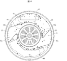
- FIG. 4 is a plan view showing a state in which an upper housing part in the main body part shown in FIG. 3 is removed.
- (A) is an enlarged view of the vicinity of the hanger portion and the upper plate portion in the mounted state
- (b) is a view of the vicinity of the hanger portion and the upper plate portion in the mounted state when using the supporting portion according to the modification. It is the figure which expanded.
- FIG. 1 It is a figure which shows the example of a structure of the main-body support part containing a fastening part, (a) is a figure which shows the state before the attachment of a fastening part, (b) is a figure which shows the state after the attachment of a fastening part, (C) is a sectional view showing a state of (b). It is a figure which shows the example of a structure of the main-body support part containing the fastening part which concerns on a modification, and is a figure which shows the state after mounting
- FIG. 1 It is a figure which shows the structural example of the main-body support part and rotation fixed part which is a modification
- (a) is a perspective view of a rotation fixed part
- (b) is a figure which shows the state before fixing by a lever part
- (C) is a figure which shows the state after fixing by the lever part.
- (A) is sectional drawing which shows an example of the torque splitter attached to the rotation fixed part
- (b) is a partial perspective view of a torque splitter.
- (b) is an exploded perspective view of a torque splitter.
- (A)-(c) is a figure which shows the example of arrangement
- FIG. 1 is a perspective view of the blower
- FIG. 1 is a perspective view of the blower
- FIG. 1 is a perspective view of the blower
- FIG. 1 is a perspective view of the blower
- FIG. 1 is a perspective view of the blower
- FIG. 1 is a perspective view of the blower
- FIG. 1 is a perspective view of the blower
- FIG. 1 is a perspective view of the blower
- FIG. 1 is a perspective view of the blower
- FIG. 1 is a perspective view of the blower
- FIG. 1 is a perspective view of the blower
- FIG. 1 is a perspective view of the blower
- FIG. 1 is a perspective view of the blower
- FIG. 1 is a perspective view of the blower
- FIG. 1 is a perspective view of the blower
- FIG. 1 is a perspective view of the blower
- FIG. 1 is a perspective view of the blower
- FIG. 1 is a perspective view of the blower
- a ceiling-mounted air blower eg, an air purifier
- the electric device include a lighting device (ceiling light), a projector, a display, and a ceiling fan.
- the electric device may be any device that is attached to the ceiling and that is supplied with power from wiring installed on the ceiling.
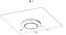
- FIG. 2 is a perspective view illustrating a state where the blower 1 is attached to a ceiling of a room.
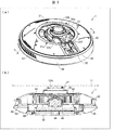
- FIG. 3A is a perspective view of the blower 1
- FIG. 3B is a sectional view of the blower 1 taken along the line AA ′.
- FIGS. 3A and 3B show a state (attachment state) in which the blower 1 is attached to the ceiling panel 11 (ceiling).
- the blower 1 is attached to a ceiling panel 11 of a house. Specifically, as shown in FIG. 3B, the ceiling panel 11 is provided with a ceiling rosette 12A. The blower 1 is attached to the ceiling rosette 12A and is supported by the ceiling rosette 12A.
- FIGS. 1A to 1C are views showing a mounting method when a main body support portion 21 (mounting device) to be described later is mounted on the ceiling closet 12A.
- the sealing rosette 12A is a so-called ceiling rosette with a hanger.
- the sealing rosette 12A has a sealing rosette body portion 12 and a hanger portion 13 (a screwing protrusion).
- the sealing rosette body 12 is provided with two hangers 13, one at each 180 ° position on the outer periphery thereof.
- Each of the two hangers 13 protrudes in the opposite direction from the sealing rosette main body 12, and has a hanger contact part 13 a that comes into contact with the upper plate 21 a of the main body support 21.
- the hanger contact portion 13a is provided with a screw fastening hole 13b into which the screw 23 is fastened.
- the weight of the blower 1 is about 8.5 kg, and the ceiling closet 12A can withstand the load of the blower 1.
- the blower 1 includes a main body support portion 21, a main body portion 22, a support member fitting portion 31, a power supply connection portion 32, and a power supply cord 33.
- the main body support 21 supports the main body 22.
- the main body support 21 functions as a mounting device for mounting the blower 1 to the ceiling closet 12A.
- the main body support portion 21 is attached to the support member fitting portion 31 in a state where the main body support portion 21 is fitted to the support member fitting portion 31 provided on the upper surface of the main body portion 22 as shown in FIG. Thus, the main body 22 is supported.
- blower 1 will be described as being provided with the main body supporting portion 21, but may be a member different from the blower 1.
- the support member fitting portion 31 is provided at the center position of the upper surface of the main body portion 22, and the main body support portion 21 is fitted therein. By connecting the main body support portion 21 and the support member fitting portion 31, the main body portion 22 is fixed to the main body support portion 21 so as not to rotate and supported.
- the support member fitting portion 31 is a member in which a member having a Z-shaped cross section is curved in a U-shape, and has an opening 31b in a part thereof.
- the main body support 21 is inserted through the opening 31b.
- the fitting protrusion 31a provided on the upper surface of the support member fitting portion 31 is located on the lower plate portion 21c of the main body supporting portion 21 at a position facing the fitting protrusion 31a.
- the main body support portion 21 is fixed to the support member fitting portion 31 by being fitted into the provided fitting hole 21f.
- the power supply connection part 32 is a member that is connected to the ceiling rosette 12A and is connected to a power supply cord 33 that is drawn from below the main body support part 21 to the upper surface of the main body part 22. Thereby, the power supplied from the wiring of the ceiling panel 11 can be supplied to the main body 22.
- the main body 22 mainly has the basic functions of the blower 1. Specifically, as shown in FIGS. 3A and 3B and FIG. 4, the main body 22 includes an upper housing 41, a blower 42, a blow passage 43, and a HEPA filter (High Efficiency Particulate Air Filter). ) 44, an illumination unit 45, an ion generating element 46, a pre-filter (not shown), a lower cover member 52, and a louvering 58.
- FIG. 4 is a plan view showing a state in which the upper casing 41 of the main body 22 shown in FIG. 3 is removed.
- the upper casing 41 is located at the top of the main body 22 and covers the inside of the main body 22 from above.
- the upper housing portion 41 has a shape in which the peripheral edge is curved downward and inclined.
- the support member fitting section 31 is attached to the upper housing section 41.
- the blower 42 is disposed at a position directly below the support member fitting portion 31, that is, the sealing rosette 12A, and includes a fan 47 and a motor 48 for rotating the fan 47.
- the fan 47 and the motor 48 are positioned at the center in the radial direction (the direction parallel to the ceiling) of the main body 22 so that the center of the fan 47 and the motor 48 in the vertical direction substantially coincides with the center of gravity of the main body 22. Is provided.
- the fan 47 is provided inside the air passage 43 as shown in FIG.
- the air passage 43 has two outlets 43a in opposite directions, and blows air from the outlets 43a when the fan 47 rotates.
- the outlet 43a is provided with a louver 57 extending vertically.
- the ion generating elements 46 are provided at positions near the two outlets 43a of the air passage 43, generate ions, and give the generated ions to the air blown out from the outlet 43a.
- the HEPA filter 44 has a function as a dust collection filter, and is provided below the main body 22. Below the HEPA filter 44, a pre-filter is provided. The pre-filter removes dust or dirt before the HEPA filter 44.
- a lower cover member 52 is provided below the pre-filter.
- a suction port 60 to the main body 22.
- the lighting unit 45 includes a lighting board 55 and a lighting cover 56 that covers the lighting board 55.
- the lighting board 55 includes a large number of LEDs and has a donut plate shape. Therefore, the blower 1 of the present embodiment also has a function as an LED device provided with LED lighting.
- the louvering 58 is formed in a ring shape and is provided between the outer peripheral portion of the upper housing portion 41 and the outer peripheral portion of the lighting cover 56.
- the louvering 58 has an opening 58a that can face the outlet 43a.
- the louvering 58 is rotatable with respect to the upper housing 41 and the illumination cover 56 by, for example, a manual operation.
- FIG. 5A is an enlarged view of the vicinity of the hanger portion 13 and the upper plate portion 21a in the attached state.
- FIG. 6 is a diagram illustrating an attached state.
- FIG. 6A is a view showing a state in which the main body supporting portion 21 is attached to the ceiling rosette 12A having the step D
- FIG. 6B is a diagram showing the main body supporting portion 21 in the ceiling closet 12A having no step D. It is a figure showing the state where was attached.
- the main body support 21 includes an upper plate 21a, a cylindrical portion 21b, a lower plate 21c, an inner wall 21d, and a rotation fixing unit 24, as shown in FIGS.
- the main body support 21 is formed of, for example, metal.
- the upper plate portion 21a is a portion that comes into contact with the hanger portion 13 (specifically, the hanger contact portion 13a) of the sealing rosette 12A.
- the upper plate portion 21a is provided with a screw hole 21e. In a state where the upper plate portion 21a and the hanger portion 13 are in contact with each other, the screw 23 is made to pass through the screw hole 21e from below, and then is fastened to the screw fastening hole 13b of the hanger portion 13, so that the ceiling rosette 12A and the main body support portion 21 is fixed.
- the upper plate portion 21a has a disk shape, and a first hole portion 25 (a circular hole) through which the sealing rosette body portion 12 can pass is formed in a central portion thereof.
- An inner wall portion 21d is provided to extend downward from an inner end of the upper plate portion 21a, and the first hole portion 25 is defined by the inner wall portion 21d.
- the first hole 25 has such a size that at least a portion of the sealing rosette body 12 located at substantially the same height as the hanger contact portion 13a can penetrate.
- the size of the first hole 25 is defined such that the sealing rosette body 12 penetrates so that the hanger contact portion 13a contacts the upper plate portion 21a.
- the lower plate portion 21c is a portion facing the main body portion 22 and is a flange portion fitted to the support member fitting portion 31.
- the cylindrical portion 21b is an intermediate portion extending vertically between the upper plate portion 21a and the lower plate portion 21c.
- the cylindrical portion 21b has a cylindrical shape with a predetermined height, and has an upper edge portion connected to the outer peripheral portion of the upper plate portion 21a.
- the lower plate portion 21c has a circular donut plate shape, and has an inner peripheral portion connected to a lower edge portion of the cylindrical portion 21b.
- a plurality of fitting holes 21f are formed over the entire circumference.
- the rotation fixing part 24 is a support part that supports the sealing rosette main body 12 through the first hole 25.
- the rotation fixing portion 24 is a cylindrical member that can be fitted into the first hole portion 25 and has a diameter substantially equal to the inner diameter of the first hole portion 25 (that is, the inner diameter of the bottom portion 12a).
- the rotation fixing part 24 is a rotation member that rotates around the rotation axis Ax (the same direction as the vertical direction) with respect to the inner wall part 21d.
- screw grooves 24a and 21da are provided on the peripheral portion (side surface portion) of the rotation fixing portion 24 and the inner wall portion 21d, respectively.
- the screw grooves 24a and 21da are provided at the same pitch, one of which is a male screw and the other is a female screw. Therefore, the rotation fixing part 24 moves in the vertical direction with respect to the inner wall part 21d by being rotated by the worker. That is, the rotation fixing portion 24 can move in the direction of inserting the sealing rosette body 12 into the first hole portion 25 or in the opposite direction (in other words, the vertical direction).
- the support portion is not limited to the rotation fixing portion 24, as long as the support portion supports the bottom portion 12a of the sealing rosette body portion 12 by being fitted into the first hole portion 25. Even in this case, the same effect as in the case where the rotation fixing portion 24 is provided can be obtained.
- a support 24 'shown in FIG. 5B can be used instead of the rotation fixing unit 24.
- FIG. 5B is an enlarged view of the vicinity of the hanger portion 13 and the upper plate portion 21a in the attached state when using the support portion 24 'according to a modification of the rotation fixing portion 24.
- the support portion 24 ' is fitted into the first hole portion 25 of the main body support portion 21' (mounting tool).
- a claw portion 24b is provided on the outer peripheral portion of the support portion 24 'instead of the screw groove 24a.
- the claw portion 24b is swingable in a left-right direction (a direction perpendicular to the up-down direction and a direction that is forward and backward with respect to the inner wall portion 21d).
- An inner wall 21d of the main body support 21 ' is provided with an uneven portion 21db (e.g., a saw-tooth uneven portion) having a plurality of concave portions and convex portions instead of the screw groove 21da.
- the claw portion 24b is engaged with the uneven portion 21db.
- the 'support portion 24' can move up and down without rotating like the rotation fixing portion 24.
- the support portion 24 ' moves upward while climbing over each convex portion of the uneven portion 21db, and its position is fixed by the concave portion when it comes into contact with the sealing rosette main body portion 12, as shown in FIG. 5B.
- the support portion 24' is moved downward while the claw portion 24b is tilted inward (in the direction of the center of the support portion 24 'and away from the inner wall 21d). Just fine.
- the claw portion 24b may be separately provided with a mechanism (link portion) for tilting the claw portion 24b inward. In this case, the claws 24b can be tilted inward without inserting a finger.
- the uneven portion 21db and the claw portion 24b lock the support portion 24 'so that the support portion 24' can move upward.
- the support portion 24 ' can be moved downward in the state as it is.
- the main body support 21 is attached to the ceiling closet 12A provided on the ceiling panel 11.
- the rotation fixing portion 24 is provided before mounting so that the sealing rosette body portion 12 penetrating the first hole portion 25 does not contact the rotation fixing portion 24 before the hanger portion 13 contacts the upper plate portion 21a. , Is located below the inner wall portion 21d.
- the operator presses the main body support 21 against the sealing rosette 12A, inserts the screw 23 into the screw hole 21e and the screw fastening hole 13b from below, and screws the screw 23. Fastened to the fastening hole 13b. This operation is similarly performed for two places (two hanger portions 13).
- the distance between the two screw fastening holes 13b formed at opposing positions is substantially constant, but the relative distance between the bottom 12a of the sealing rosette body 12 and the hanger portion 13 is relatively small.
- the position is not constant.
- a hanger portion 13 is provided at a position away from the bottom portion 12a of the sealing rosette body 12 in the height direction (upward) as the sealing rosette 12A.
- a sealing rosette 12A having a step D of about several millimeters.
- the height of the bottom 12a of the sealing rosette body 12 and the height of the hanger contact portion 13a are substantially the same (the bottom 12a and the hanger contact portion 13a are substantially flush with each other).
- a sealing rosette 12A is also a).
- the sealing rosette 12A has no step D.
- the main body support 21 is provided with the first hole 25 through which the sealing rosette main body 12 can pass as described above. Therefore, regardless of the presence or absence of the step D, the hanger contact portion 13a and the upper plate portion 21a come into contact with each other when the sealing rosette body portion 12 penetrates the first hole portion 25.
- the main body supporting portion 21 is fixed to the sealing rosette 12A with the upper plate portion 21a in contact with the hanger portion 13 regardless of the presence or absence of the step D. it can.
- the operator lifts the main body 22 to the position of the ceiling panel 11, fits the support member fitting portion 31 to the main body support portion 21, and fits the fitting convex portion 31a into the fitting hole 21f. .
- the main body 22 is fixed to the main body support 21 so as not to rotate.
- a power cord cover (not shown) is attached to the main body 22 so as to cover the power cord 33.
- FIGS. 7A and 7B are views showing an attached state of the main body supporting portion 210 of Comparative Example 1 and the ceiling closet 12A without a step D, wherein FIG. 7A is a perspective view and FIG. 7B is a sectional view.
- FIGS. 8A and 8B are views showing a mounting state of the main body supporting portion 210 of Comparative Example 1 and the ceiling rosette 12A having the step D, wherein FIG. 8A is a perspective view and FIG. 8B is a cross-sectional view.
- FIGS. 9A and 9B are cross-sectional views illustrating a mounting state of the main body support portion 211 of Comparative Example 2 and the sealing rosette 12A having the step D.
- a hole 250 is also provided in the upper plate portion 210a of the main body support portion 210, and the diameter of the hole portion 250 is the sealing rosette body portion. 12 is smaller than the diameter of the bottom 12a. Therefore, the sealing rosette body 12 (at least the portion of the sealing rosette body 12 located at substantially the same height as the hanger contact portion 13a) is not inserted into the hole 250.
- the size (dimensional tolerance) of the step D varies depending on the sealing rosette 12A. Therefore, in the case of the main body supporting portion 210, it is necessary to prepare the spacers 300 having various thicknesses corresponding to the steps D having various sizes. Further, it is not easy for an operator to select an appropriate spacer 300 according to the step D. Therefore, it is necessary to increase the margin for allowing a certain gap or to prepare a measuring jig for measuring the step D.
- the above-mentioned margin indicates an allowable range of fixing strength between the blower 1 and the sealing rosette 12A.
- the screw 23 cannot be sufficiently tightened, but even in that case, the blower 1 needs to be fixed to the ceiling closet 12A with a necessary and sufficient fixing strength. is there. That is, it is necessary that the fixing strength is guaranteed through evaluation and the like.
- the fixed strength is "guaranteed to seismic intensity 6 equivalent to earthquake vibration".
- the ceiling strength of the ceiling closet 12A and the blower 1 must be guaranteed up to a seismic intensity of 6 or more.
- a guarantee up to a seismic intensity of 8 is provided, and even if a 1 mm gap is formed, the warranty is not provided.
- the degree is reduced, it is guaranteed up to seismic intensity 7 or equivalent.
- the main body support portion 210 is used, even if there is a certain gap, it is necessary to secure a margin for securing the fixing strength in anticipation of the gap.
- the upper plate portion 211a of the main body support portion 211 has a hole 251 through which the sealing rosette main body portion 12 (at least a portion of the sealing rosette main body portion 12 located at substantially the same height as the hanger contact portion 13a) can pass.
- the upper plate portion 211a is provided with the hole 251 having the same size as the first hole 25 of the main body support portion 21. Therefore, as shown in FIG. 9A, even with the sealing rosette 12A having the step D, the bottom portion 12a of the sealing rosette main body portion 12 does not contact the upper plate portion 211a. As a result, the screw 23 can be sufficiently tightened.
- the main body support portion 211 is fixed to the sealing rosette 12A only at two places where the screws 23 are tightened. Therefore, as shown in FIG. 9B, the main body support portion 211 easily swings around the screw 23. Therefore, also in this case, the main body supporting portion 211 cannot be stably fixed to the sealing rosette 12A.
- the hanger contact can be performed regardless of the presence or absence of the step D.
- the portion 13a can be brought into contact with the upper plate portion 21a.
- the main body support portion 21 of the present embodiment by having the first hole portion 25 and the rotation fixing portion 24, the presence or absence of the step D is not considered (that is, regardless of the shape of the sealing rosette 12A).
- the main body support 21 can be stably fixed to the ceiling rosette 12A. That is, the main body support portion 21 can flexibly correspond to various shapes of the sealing rosette 12A.
- the main body supporting portion 21 can be easily and stably fixed to the sealing rosette 12A.
- the labor of the operator for stably fixing the fixing member can be reduced, it is possible to prevent a malfunction or an accident due to a mounting error.
- the support unit can be realized with a simple configuration.
- FIGS. 10A and 10B are diagrams illustrating a configuration example of the rotation fixing unit 24, where FIG. 10A is a cross-sectional view and FIG. 10B is a plan view.
- a grip portion 24c that is gripped by an operator to rotate the rotation fixing portion 24 around the rotation axis Ax is provided at the bottom of the rotation fixing portion 24. It does not matter. Thus, the operator can easily rotate the rotation fixing unit 24.
- a stamp, a seal or an illustration indicating the rotation direction may be attached to the bottom of the rotation fixing unit 24. Absent. In FIG. 10B, the characters "open ⁇ ⁇ close" are added.
- the main body support portion 21 may include a fixing portion (loosening prevention mechanism) for fixing the rotation fixing portion 24 in the mounted state.
- the provision of the fixing portion can prevent the rotation fixing portion 24 from being loosened in the mounted state.
- a mechanism as shown in FIGS. 11 to 13 can be exemplified.
- FIGS. 11A and 11B are diagrams illustrating a configuration example of the main body support portion 21 including the fastening portion 26 (fixed portion), where FIG. 11A is a diagram illustrating a state before the fastening portion 26 is attached, and FIG. It is a figure which shows the state after mounting
- the fastening portion 26 is an annular member having an inner diameter equal to the diameter of the rotation fixing portion 24, and the inner wall thereof has the same pitch as the thread groove 24 a provided in the rotation fixing portion 24. Is a nut provided with a thread groove 26a.
- FIG. 11A after the tightening of the rotation fixing unit 24 is completed (after the rotation fixing unit 24 comes into contact with the bottom 12 a of the sealing rosette body 12), the tightening unit 26 is fixed to the rotation fixing unit 24. It fits into the rotation fixing part 24 from below. Then, as shown in FIGS. 11B and 11C, the tightening portion 26 is tightened until it comes into contact with the inner wall portion 21d.
- the inner wall portion 21d and the tightening portion 26 function as a double nut. Therefore, loosening of the rotation fixing portion 24 in the mounted state can be prevented by tightening the tightening portion 26.
- FIG. 12 is a diagram illustrating a configuration example of the main body support portion 21 including a fastening portion 26A (fixed portion) according to a modification of the fastening portion 26, and is a diagram illustrating a state after the fastening portion 26A is attached.
- the tightening portion 26A has the same diameter as the diameter of the rotation fixing portion 24, and a screw groove 26aa having the same pitch as the screw groove 24a of the rotation fixing portion 24 is provided on the outer periphery thereof. That is, the fastening portion 26A can be screwed into the inner wall portion 21d, similarly to the rotation fixing portion 24. After the fastening of the rotation fixing portion 24 is completed, the fastening portion 26A is screwed into the inner wall portion 21d from below the rotation fixing portion 24 to prevent the rotation fixing portion 24 from being loosened. That is, since the same effect as the double nut is obtained by screwing the rotation fixing portion 24 and the tightening portion 26A into the inner wall portion 21d, it is possible to suppress the rotation fixing portion 24 from being loosened.
- FIG. 13 is a diagram illustrating a configuration example of a main body support portion 21A (attachment device) and a rotation fixing portion 24A (support portion, rotating member) which are modifications of the main body support portion 21 and the rotation fixing portion 24.
- 13A is a perspective view of the rotation fixing portion 24A
- FIG. 13B is a diagram showing a state before being fixed by the lever portion 27 (fixing portion, claw portion), and FIG. It is a figure showing the state after fixation.
- the rotation fixing portion 24A has a cutout portion 24Aa.
- a plurality of notches 24Aa are provided along the circumferential direction at the outer edge of the rotation fixing portion 24A.
- the main body supporting portion 21A is a lever partially fitted into the cutout portion 24Aa of the rotation fixing portion 24A fitted on the inner wall portion 21d.
- a portion 27 is provided.
- the lever portion 27 is provided so as to be able to pass through a through hole (not shown) provided in the inner wall portion 21d.
- ((B) of FIG. 13 shows a state in which the main body supporting portion 21A is fixed to the ceiling closet 12A by the screw 23, and before the rotation fixing portion 24A is tightened.
- at least a part of the lever portion 27 is located outside the inner wall portion 21d.
- the lever portion 27 only needs to be retracted to a position where the movement of the rotation fixing portion 24A is not hindered.
- the lever portions 27 may be provided at a plurality of locations along the inner wall portion 21d.
- the main body support portion 21 may include a mechanism for preventing the rotation fixing portion 24 from being overtightened.
- a mechanism for preventing the rotation fixing portion 24 from being overtightened for example, a mechanism that causes the rotation fixing unit 24 to idle when a torque equal to or more than a predetermined torque is applied to the rotation fixing unit 24 is exemplified.
- FIG. 14A is a cross-sectional view illustrating an example of the torque splitter 100 attached to the rotation fixing unit 24, and FIG. 14B is a partial perspective view of the torque splitter 100.
- FIGS. 15A and 15B are exploded perspective views of the torque splitter 100.
- FIG. 14B illustrates a state in which a part of the outer case 104 is removed (that is, a part of the internal structure of the torque splitter 100).
- FIG. 15A is a diagram of the torque splitter 100 as viewed obliquely from above
- FIG. 15B is a diagram of the torque splitter 100 as viewed obliquely from below.
- the torque splitter 100 includes a spring fixing portion 101, a spring 102, an internal ratchet mechanism 103, and an outer case 104. It has.
- a through hole that penetrates the screw 200 is provided in the center of the rotation fixing part 24. I have.
- the torque splitter 100 is fixed to the rotation fixing part 24 by a screw 200.
- the screw 200 fixes the rotation fixing part 24 and the internal ratchet mechanism 103.
- the rotation fixing unit 24 rotates in conjunction with the rotation of the torque splitter 100 until a predetermined torque is applied.
- the spring fixing portion 101 fixes the spring 102 together with the internal ratchet mechanism 103 at the center thereof. Further, the spring fixing portion 101 is connected to the outer case 104. Thus, by rotating the outer case 104, the spring fixing portion 101 rotates in conjunction with the outer case 104.
- the spring 102 is provided between the spring fixing portion 101 and the internal ratchet mechanism 103.
- the ratchet portion 103a formed on the outer wall at the bottom of the inner ratchet mechanism 103 and the ratchet portion 104a formed on the inner wall at the bottom of the outer case 104 come into contact at the meshing position EP by the force of the spring 102 (meshing). ).
- the ratchet portion 103a and the ratchet portion 104a have an uneven portion having a plurality of concave portions and convex portions (eg, a saw-tooth uneven portion).
- One of the ratchet portion 103a and the ratchet portion 104a has a convex portion that is erected in an inclined state, and the other is a convex portion that is erected vertically (extended upward or downward). have.
- a description will be given assuming that the ratchet portion 103a has a vertically erected protrusion and the ratchet portion 104a has a sloping protrusion.
- the spring 102 is provided so that the spring fixing portion 101 and the internal ratchet mechanism 103 are in contact with each other. Therefore, when the spring fixing portion 101 is rotated by rotating the outer case 104, if the torque is less than a predetermined torque, the internal ratchet mechanism 103 rotates. This is because the force of the protrusion of the ratchet portion 103a over the slope of the protrusion of the ratchet portion 104a (the force of climbing over the slope) is small, so that the protrusion does not climb over the slope. In this case, the rotation fixing unit 24 rotates in conjunction with the rotation of the internal ratchet mechanism 103.
- the predetermined torque is set by, for example, an experiment or the like by adjusting the stress of the spring 102 to such an extent that the rotation fixing portion 24 is not excessively tightened (for example, the rotation fixing portion 24 or the sealing rosette 12A is not broken).
- the predetermined torque for example, a value to be applied when the rotation fixing unit 24 contacts the bottom 12a of the sealing rosette body 12 may be set.
- the rotation of the rotation fixing unit 24 may be automated if safety in tightening the rotation fixing unit 24 is considered.
- a driving unit eg, a motor
- the operator may control the rotation of the rotation fixing unit 24 (that is, the movement in the vertical direction) by controlling the driving unit using a remote controller, for example.
- FIGS. 16A to 16C are diagrams showing examples of the arrangement of the LEDs 70.
- FIG. FIGS. 16A to 16C are enlarged views of the vicinity of the arrangement of the LEDs 70 when the main body 22 is viewed from above.
- the illumination board 55 is provided with a plurality of LEDs 70. As shown in FIGS. 16 (a) to 16 (c), at least a part of them is arranged so that the light emission direction is substantially horizontal (direction substantially perpendicular to the vertical direction).
- the projected image formed by the light emitted from the LED 70 is substantially circular.
- the following three methods can be considered. -Increase the distance between the LED 70 and the illumination cover 56 (the part to be irradiated with the light emitted from the LED 70). -Provide more LEDs 70.
- An optical member eg, a lens is provided between the LED 70 and the illumination cover 56.
- FIG. 16A consider a case where the LED 70 is provided such that the optical axis Ax10 of the LED 70 is substantially perpendicular to the illumination cover 56.
- FIG. 16B if the LED 70 is moved to an arrangement position P2 farther from the illumination cover 56 than the arrangement position P1 of the LED 70 shown in FIG.
- the irradiation range IA can be wider than in the case of a).
- components cannot be mounted in the light emitting direction of the LED 70.
- FIG. 16B since the LED 70 is disposed inside the main body 22 as compared with the case of FIG. 16A, components cannot be mounted more than in the case of FIG. Range increases. Therefore, space efficiency is reduced.
- FIG. 16B there is a possibility that a trouble such as changing the arrangement position of the illumination board 55 on which the LEDs 70 are arranged is required to mount the components.
- the LED 70 is arranged at the arrangement position P1 such that the optical axis Ax10 of the LED 70 is oriented in a direction different from the direction substantially perpendicular to the illumination cover 56 (that is, in an oblique direction). .
- the LEDs 70 are arranged such that the optical axes Ax10 of two adjacent LEDs 70 face in the direction in which they face each other.
- the LEDs 70 on the lighting board 55 are rarely attached so as to face in an oblique direction due to the manufacturing method or quality control.
- the boundary of the irradiation range of the light emitted from each LED 70 is ambiguous, even if the LED 70 is mounted obliquely, there is almost no actual harm in production technology.
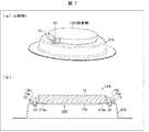
- FIG. 17A is a perspective view of the blower 1B
- FIG. 17B is a cross-sectional view of the blower 1B along the line BB '.
- FIGS. 17A and 17B show a state in which the blower 1B is attached to the ceiling panel 11 (attached state).
- the basic configuration of the air blower 1B is the same as that of the air blower 1, but the air blower 1B is different from the air blower 1 in that the air blower 1B includes a main body support 21B (attachment device) instead of the main body support 21. .
- the main body supporting portion 21B serves as a supporting portion that supports the sealing rosette main body portion 12 of the sealing rosette 12B via the first hole 25.
- a support plate 84 (support portion) is provided instead of the rotation fixing portion 24.
- a spring 85 (expandable member) for moving the support plate 84 in the vertical direction is provided.
- the sealing rosette 12B according to the first embodiment is different from the sealing rosette 12 according to the first embodiment in that a sealing cover 12b is provided at the bottom of the sealing rosette body 12, as shown in FIGS. Different from 12A.
- the rosette cover 12b covers the ceiling rosette body 12.
- Hangers 13 are connected to two places on the outer edge of the rosette cover 12b.
- the rosette cover 12b and the hanger portion 13 may be provided integrally, or may be provided separately.
- the sealing rosette 12A may be used in the present embodiment
- the sealing rosette 12B may be used in the first embodiment.
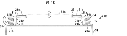
- FIG. 18 is a cross-sectional view of the main body support 21B.
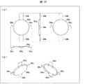
- 19A and 19B are diagrams illustrating a configuration example of the support plate 84, FIG. 19A is a plan view and a side view, and FIG. 19B is a perspective view.
- the support plate 84 includes a contact portion 84 a that contacts the ceiling rosette body 12 via the first hole 25, and a protrusion 84 b protruding from the contact portion 84 a.
- a second hole 21g is provided in the cylindrical portion 21b (side wall) of the main body support 21B.
- a protrusion 84b is provided through the second hole 21g.
- the second hole 21g is opened in the vertical direction at least by the amount of movement of the protrusion 84b so as to allow the protrusion 84b to move in the vertical direction.
- a spring 85 that extends and contracts in the up-down direction is provided on a part (eg, an end) of the protruding portion 84b protruding from the second hole 21g.
- the spring 85 is connected to a part of the protruding part 84b and a part of the lower plate part 21c. Due to the connection of the spring 85, a force is applied to the protruding portion 84b and the lower plate portion 21c in a direction away from each other.
- the expansion and contraction of the spring 85 allows the support plate 84 to move vertically. That is, the spring 85 holds the support plate 84 so that the support plate 84 can move up and down.
- the contact portion 84a can penetrate the first hole 25 and the inside diameter of the first hole 25 (that is, the inside diameter of the rosette cover 12b (bottom)). And a circular plate portion having substantially the same diameter.
- the main body 22 can be stably fixed to the ceiling rosette 12B in the mounted state.
- the shape and size of the contact portion 84a are not limited thereto, and may be any shape and size that can penetrate the first hole portion 25 and can support the sealing rosette body 12.
- the projecting portion 84b is provided at positions (two places) facing each other on the outer edge of the contact portion 84a.
- the position where the protruding portion 84b is provided may be a position where the protruding portion 84b protrudes from the second hole 21g when the support plate 84 is provided on the main body supporting portion 21B. Further, in the present embodiment, it is provided at two places, but the number is not limited.
- the contact portion 84a comes into contact with the rosette cover 12b, the contact portion 84a only needs to be provided to the extent that the contact portion 84a can move in the vertical direction stably.
- the number and formation position of the second holes 21g and the number and arrangement position of the springs 85 are determined according to the number and arrangement position of the protrusions 84b.
- the support plate 84 further includes a protrusion preventing portion 84c for preventing the contact portion 84a from excessively protruding from the first hole 25.
- the protrusion preventing portion 84c is provided at a position (two places) facing each other on the outer edge portion of the contact portion 84a (however, a position where the protrusion 84b is not provided).
- the number and the arrangement position of the protrusion prevention portions 84c are not limited to the above-mentioned number and arrangement position, as long as the excessive protrusion of the contact portion 84a by the spring 85 can be prevented stably.
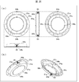
- FIG. 20 is a diagram showing a configuration example of the main body support portion 21B to which the support plate 84 and the spring 85 are attached, (a) is a plan view and a side view, and (b) is a perspective view.
- the contact portion 84a is provided to slightly protrude from the first hole 25 in order to easily support the sealing rosette main body 12.
- the protrusion preventing portion 84c contacts the upper plate portion 21a (back side)
- the amount of protrusion of the contact portion 84a from the first hole 25 is defined. I have.
- the spring 85 is connected to a part of the lower plate 21c and the end of the protrusion 84b as described above.
- the spring 85 may be provided between the support plate 84 and the main body 22.
- the main body 22 is attached to the main body support 21B by fitting the fitting protrusion 31a into the fitting hole 21f after fitting to the support member fitting portion 31.
- the main body support portion 21B and the main body portion 22 are integrated. Therefore, for example, even when one end of the spring 85 is provided in a part of the main body 22, the spring 85 can exhibit the same function as that when it is attached to the lower plate 21 c.
- one end of the spring 85 may be provided in a part of the support member fitting portion 31.
- the integrated main body supporting portion 21B and the main body portion 22 are attached to the sealing rosette 12B. Therefore, it is preferable that one end of the spring 85 be provided on the lower plate portion 21c in consideration of ease of attachment or safety.
- a spring 85 is used as a telescopic member that expands and contracts in the vertical direction.
- any member other than the spring 85 eg, rubber, resin, An elastic member such as a thermoplastic elastomer may be used.
- FIG. 21 is a diagram showing an attached state.
- FIG. 21A is a diagram illustrating a state in which the main body supporting portion 21B is attached to the ceiling closet 12B having the step D
- FIG. 21B is a diagram illustrating the main body supporting portion 21B in the ceiling closet 12B having no step D. It is a figure showing the state where was attached.
- a step D exists between the rosette cover 12b and the hanger contact portion 13a as shown in FIG. 21A.
- the contact portion 84a comes into contact with the rosette cover 12b. Since the step D exists, in this contact state, the upper plate portion 21a and the hanger contact portion 13a are not in contact.
- the screw 23 is tightened in this contact state, since the support plate 84 is connected to the spring 85, the support plate 84 is pushed down, and the sealing rosette body 12 is inserted into the first hole 25. As a result, the screw 23 can be tightened until the upper plate portion 21a contacts the hanger contact portion 13a (until the gap caused by the step D disappears).
- the spring 85 is provided between the support plate 84 and the main body 22 (specifically, the lower plate 21c of the main body support 21B). Therefore, as in the first embodiment, the main body supporting portion 21B can be stably and easily fixed to the ceiling closet 12B regardless of the shape of the ceiling closet 12B. In addition, since the support plate 84 is supported by the spring 85, even when a vibration due to an earthquake or the like occurs, the vibration of the main body 22 can be suppressed. That is, it is possible to improve the earthquake resistance of the blower 1B in the attached state.
- the mounting device is a mounting device for mounting an electric device on a ceiling rosette, wherein the first hole portion through which a sealing rosette body of the ceiling rosette can pass, and the first hole portion are provided. And a support for supporting the sealing rosette main body through the main body, wherein the support is movable along a direction in which the sealing rosette main body is inserted into the first hole or a direction opposite thereto.
- the support portion may support the bottom portion of the sealing rosette main body portion by being fitted into the first hole portion.
- a screw groove is provided in each of the support portion and an inner wall portion of the mounting device that defines the first hole, and the support portion includes the inner wall.
- a rotating member that rotates with respect to the part may be used.
- the mounting tool according to aspect 4 of the present invention in any one of aspects 1 to 3, in which the sealing rosette main body is supported by the support portion, so that the mounting tool is mounted on the ceiling rosette.
- a fixing portion for fixing the support portion may be provided.
- An attachment device in the first aspect, further includes an elastic member that expands and contracts along the insertion direction or the opposite direction, wherein the elastic member is provided between the support portion and the main body of the electric device. May be provided.
- the mounting device in the aspect 5, further comprises a lower plate portion facing the main body portion of the electric device, wherein the support portion contacts the sealing rosette main body portion via the first hole. And a projecting portion projecting from the contacting portion.
- the projecting portion penetrates the side wall of the mounting tool, and the projecting portion can be moved in the insertion direction or the opposite direction.
- a second hole may be provided, and the elastic member may be connected to a part of the protruding part protruding from the second hole and a part of the lower plate part.
- An electric device according to an aspect 7 of the present invention is the electric device attached to the ceiling rosette, and includes the attachment device according to any one of the aspects 1 to 6.
Landscapes
- Engineering & Computer Science (AREA)
- General Engineering & Computer Science (AREA)
- Mechanical Engineering (AREA)
- Chemical & Material Sciences (AREA)
- Combustion & Propulsion (AREA)
- Connector Housings Or Holding Contact Members (AREA)
- Non-Portable Lighting Devices Or Systems Thereof (AREA)
Abstract
簡易な手法で、シーリングローゼットに電気機器を取り付けることができる。本体支持部(21)は、シーリングローゼット本体部(12)が貫通可能な第1孔部(25)と、第1孔部を介してシーリングローゼット本体部を支持する回転固定部(24)と、を備える。回転固定部は、シーリングローゼット本体部の第1孔部への挿入方向又はその逆方向に沿って移動可能である。
Description
本発明は、シーリングローゼットに電気機器を取り付けるための取付器具に関する。
従来から、家屋の天井に設けられたシーリングローゼットに取り付けられることで、シーリングローゼットから給電される各種電気機器が知られている。当該電気機器の例が、特許文献1に開示されている。特許文献1の天井取付け照明器具は、シーリングローゼットの左右のいわゆるハンガー部にねじにて固定される。
シーリングローゼットの形状によっては、シーリングローゼットと電気機器との間に段差(隙間)が生じるか否か、及び、段差が生じている場合にはどの程度の段差であるのかを考慮しながら、シーリングローゼットに電気機器を取り付ける必要がある。特許文献1では、このような段差に関する検討はなされていない。
本発明の一態様は、簡易な手法で、シーリングローゼットに電気機器を取り付けることが可能な取付器具を実現することを目的とする。
上記の課題を解決するために、本発明の一態様に係る取付器具は、シーリングローゼットに電気機器を取り付けるための取付器具であって、前記シーリングローゼットのシーリングローゼット本体部が貫通可能な第1孔部と、前記第1孔部を介して前記シーリングローゼット本体部を支持する支持部と、を備え、前記支持部は、前記シーリングローゼット本体部の前記第1孔部への挿入方向又はその逆方向に沿って移動可能である。
本発明の一態様によれば、簡易な手法で、シーリングローゼットに電気機器を取り付けることができる。
〔実施形態1〕
本発明の実施形態を図面に基づいて以下に説明する。なお、本書では、天井に設けられたシーリングローゼットに取り付けられる電気機器として、天井取付型の送風装置(例:空気清浄機)を例に挙げて説明する。しかし、これに限らず、電気機器としては、例えば、照明装置(シーリングライト)、プロジェクタ、ディスプレイ、又はシーリングファンが挙げられる。つまり、電気機器は、天井に取り付けれ、かつ、天井に設置された配線から給電される機器であればよい。
本発明の実施形態を図面に基づいて以下に説明する。なお、本書では、天井に設けられたシーリングローゼットに取り付けられる電気機器として、天井取付型の送風装置(例:空気清浄機)を例に挙げて説明する。しかし、これに限らず、電気機器としては、例えば、照明装置(シーリングライト)、プロジェクタ、ディスプレイ、又はシーリングファンが挙げられる。つまり、電気機器は、天井に取り付けれ、かつ、天井に設置された配線から給電される機器であればよい。
<送風装置の天井への取り付け構造>
図2は、送風装置1を部屋の天井へ取り付けた状態を示す斜視図である。図3の(a)は、送風装置1の斜視図であり、(b)は、送風装置1のA-A’断面図である。図3の(a)及び(b)は、送風装置1が天井パネル11(天井)に取り付けられた状態(取付状態)を示している。
図2は、送風装置1を部屋の天井へ取り付けた状態を示す斜視図である。図3の(a)は、送風装置1の斜視図であり、(b)は、送風装置1のA-A’断面図である。図3の(a)及び(b)は、送風装置1が天井パネル11(天井)に取り付けられた状態(取付状態)を示している。
図2に示すように、送風装置1は、家屋の天井パネル11に取り付けられている。具体的には、図3の(b)に示すように、天井パネル11にはシーリングローゼット12Aが設けられている。送風装置1は、シーリングローゼット12Aに取り付けられ、かつシーリングローゼット12Aにより支持されている。
<シーリングローゼットの構成>
図1の(a)~(c)は、後述する本体支持部21(取付器具)がシーリングローゼット12Aに取り付けられるときの取付方法を示す図である。図1に示すように、シーリングローゼット12Aは、いわゆるハンガー付きのシーリングローゼットである。図1の(a)~(c)に示すように、シーリングローゼット12Aは、シーリングローゼット本体部12と、ハンガー部13(ねじ締め突起部)とを有している。シーリングローゼット本体部12には、その外周部の180度ごとの位置に各1個、合計2個のハンガー部13が設けられている。2個のハンガー部13は、それぞれシーリングローゼット本体部12から反対方向へ突出した状態となっており、本体支持部21の上板部21aと接触するハンガー接触部13aを有する。ハンガー接触部13aには、ねじ23が締結されるねじ締結孔13bが設けられている。
図1の(a)~(c)は、後述する本体支持部21(取付器具)がシーリングローゼット12Aに取り付けられるときの取付方法を示す図である。図1に示すように、シーリングローゼット12Aは、いわゆるハンガー付きのシーリングローゼットである。図1の(a)~(c)に示すように、シーリングローゼット12Aは、シーリングローゼット本体部12と、ハンガー部13(ねじ締め突起部)とを有している。シーリングローゼット本体部12には、その外周部の180度ごとの位置に各1個、合計2個のハンガー部13が設けられている。2個のハンガー部13は、それぞれシーリングローゼット本体部12から反対方向へ突出した状態となっており、本体支持部21の上板部21aと接触するハンガー接触部13aを有する。ハンガー接触部13aには、ねじ23が締結されるねじ締結孔13bが設けられている。
一例として、送風装置1の重量は、約8.5kgであり、シーリングローゼット12Aは、送風装置1の荷重に耐え得るものである。
<送風装置の構成>
送風装置1は、図3の(a)及び(b)に示すように、本体支持部21、本体部22、支持部材嵌合部31、電源接続部32、及び電源コード33を備えている。
送風装置1は、図3の(a)及び(b)に示すように、本体支持部21、本体部22、支持部材嵌合部31、電源接続部32、及び電源コード33を備えている。
本体支持部21は、本体部22を支持するものである。また、本体支持部21は、シーリングローゼット12Aに送風装置1を取り付けるための取付器具として機能する。本体支持部21は、図3の(a)に示すように、本体部22の上面部に設けられた支持部材嵌合部31に嵌合された状態で、支持部材嵌合部31に取り付けられることで本体部22を支持する。
なお、本書では、送風装置1に本体支持部21が備えられるものとして説明するが、送風装置1とは異なる部材であっても構わない。
支持部材嵌合部31は、本体部22の上面部の中央位置に設けられており、本体支持部21が嵌合される。本体支持部21と支持部材嵌合部31とが連結されることにより、本体部22は、本体支持部21に回転しないように固定され、かつ支持される。
支持部材嵌合部31は、断面Z形状の部材をU字形に湾曲させた状態のものであり、その一部に開口部31bを有する。開口部31bから本体支持部21が挿入される。挿入された状態において、支持部材嵌合部31の上面部に設けられた嵌合凸部31aが、当該嵌合凸部31aと対向する位置となった、本体支持部21の下板部21cに設けられた嵌合孔21fに嵌合されることで、本体支持部21は支持部材嵌合部31に固定される。
電源接続部32は、シーリングローゼット12Aと接続され、かつ、本体支持部21の下から本体部22の上面部へ引き出されている電源コード33が接続される部材である。これにより、天井パネル11の配線から給電された電力を、本体部22に供給できる。
本体部22は、主として、送風装置1の基本的な機能を備えている。具体的には、図3の(a)及び(b)、並びに図4に示すように、本体部22は、上筐体部41、送風機42、送風通路43、HEPAフィルタ(High Efficiency Particulate Air Filter)44、照明部45、イオン発生素子46、プレフィルタ(不図示)、下部カバー部材52、及びルーバリング58を備えている。図4は、図3に示した本体部22における上筐体部41を除去した状態を示す平面図である。
上筐体部41は、本体部22の最上部に位置し、本体部22の内部を上から覆っている。上筐体部41は、周縁部が下方へ湾曲して傾斜した形状となっている。上筐体部41には、上記支持部材嵌合部31が取り付けられている。
送風機42は、支持部材嵌合部31すなわちシーリングローゼット12Aの真下の位置に配置され、ファン47、及びファン47を回転させるモータ48を備えている。これらファン47及びモータ48は、鉛直方向において、これらファン47及びモータ48の中心が本体部22の重心とほぼ一致するように、本体部22の径方向(天井と平行な方向)の中央部に設けられている。
ファン47は、図4に示すように、送風通路43の内部に設けられている。送風通路43は、二つの吹出口43aを反対方向に有し、ファン47が回転することにより、それら吹出口43aから空気を吹き出すようになっている。吹出口43aには、上下方向に延びるルーバ57が設けられている。
イオン発生素子46は、送風通路43の二つの吹出口43aの近傍位置にそれぞれ設けられ、イオンを発生し、発生したイオンを吹出口43aから吹き出される空気に与える。
HEPAフィルタ44は、集塵フィルタとしての機能を有し、本体部22の下部に設けられている。HEPAフィルタ44の下には、プレフィルタが設けられている。プレフィルタは、HEPAフィルタ44の前段にて、埃又はゴミを除去する。
プレフィルタの下方には下部カバー部材52が設けられている。下部カバー部材52の周りは、本体部22への吸込口60となっている。
照明部45は、照明基板55、及び照明基板55を覆う照明カバー56を備えている。照明基板55は、多数のLEDを備え、ドーナツ板形状を有している。従って、本実施形態の送風装置1は、LED照明を備えたLED装置としての機能も有する。
ルーバリング58は、環状に形成され、上筐体部41の外周部と照明カバー56の外周部との間に設けられている。ルーバリング58は、吹出口43aに対向可能な開口部58aを有する。ルーバリング58は、例えば手動操作により、上筐体部41及び照明カバー56に対して回転可能となっている。
<本体支持部の詳細>
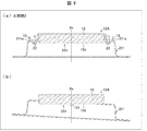
次に、本体支持部21の詳細について説明する。図5の(a)は、取付状態におけるハンガー部13及び上板部21a付近を拡大した図である。図6は、取付状態を示す図である。図6の(a)は、段差Dが存在するシーリングローゼット12Aに本体支持部21が取り付けられた状態を示す図であり、(b)は、段差Dが存在しないシーリングローゼット12Aに本体支持部21が取り付けられた状態を示す図である。
次に、本体支持部21の詳細について説明する。図5の(a)は、取付状態におけるハンガー部13及び上板部21a付近を拡大した図である。図6は、取付状態を示す図である。図6の(a)は、段差Dが存在するシーリングローゼット12Aに本体支持部21が取り付けられた状態を示す図であり、(b)は、段差Dが存在しないシーリングローゼット12Aに本体支持部21が取り付けられた状態を示す図である。
本体支持部21は、図1の(a)及び図5の(a)に示すように、上板部21a、円筒部21b、下板部21c、内壁部21d、及び回転固定部24を備える。本体支持部21は、例えば金属にて形成される。
上板部21aは、シーリングローゼット12Aのハンガー部13(具体的にはハンガー接触部13a)と接触する部分である。上板部21aには、ねじ孔21eが設けられている。上板部21aとハンガー部13とが接触した状態で、ねじ23を下方からねじ孔21eを貫通させた後、ハンガー部13のねじ締結孔13bに締結させることで、シーリングローゼット12Aと本体支持部21とを固定する。
上板部21aは、円板形状を有し、その中央部には、シーリングローゼット本体部12が貫通可能な第1孔部25(円形孔)が形成されている。上板部21aの内側端部から下方に延伸するように内壁部21dが設けられており、内壁部21dによって第1孔部25が規定されている。
第1孔部25は、少なくとも、ハンガー接触部13aと略同一の高さに位置するシーリングローゼット本体部12の部分が貫通可能な程度の大きさを有する。つまり、ハンガー接触部13aが上板部21aと接触するようにシーリングローゼット本体部12が貫通するように、第1孔部25の大きさが規定されている。
下板部21cは、本体部22と対向する部分であり、支持部材嵌合部31と嵌合する鍔部である。円筒部21bは、上板部21aと下板部21cとの間に、上下方向に延びる中間部である。
円筒部21bは、所定高さの円筒形を有し、上縁部が上板部21aの外周部とつながっている。下板部21cは、円形のドーナツ板形状であり、内周部が円筒部21bの下縁部とつながっている。下板部21cには、複数の嵌合孔21f(図3の(a)参照)が全周に亘って形成されている。
回転固定部24は、第1孔部25を介してシーリングローゼット本体部12を支持する支持部である。回転固定部24は、第1孔部25に嵌合可能に、かつ、第1孔部25の内径(つまり底部12aの内径)と略同一の直径を有する円柱部材である。
また、回転固定部24は、内壁部21dに対して、回転軸Ax(上下方向と同方向)の周りに回転する回転部材である。図5の(a)に示すように、回転固定部24の周縁部(側面部)、及び内壁部21dのそれぞれには、ねじ溝24a及び21daが設けられている。ねじ溝24a及び21daは同ピッチで設けられており、その一方が雄ねじ、他方が雌ねじである。そのため、回転固定部24は、作業者により回転されることにより、内壁部21dに対して上下方向に移動する。つまり、回転固定部24は、シーリングローゼット本体部12の第1孔部25への挿入方向又はその逆方向(換言すれば上下方向)に沿って移動できる。
なお、上記支持部は、第1孔部25に嵌合されることにより、シーリングローゼット本体部12の底部12aを支持するものであればよく、回転固定部24に限定されるものではない。この場合であっても、回転固定部24を備えた場合と同様の効果を奏することができる。上記支持部として、例えば、回転固定部24に代えて、図5の(b)に示す支持部24’を用いることができる。図5の(b)は、回転固定部24の変形例に係る支持部24’を用いた場合の、取付状態におけるハンガー部13及び上板部21a付近を拡大した図である。
図5の(b)に示すように、支持部24’は、本体支持部21’(取付器具)の第1孔部25に嵌合される。支持部24’の外周部には、ねじ溝24aに代えて、爪部24bが設けられている。爪部24bは、左右方向(上下方向に垂直な方向であって、内壁部21dに対して前後する方向)に揺動可能である。本体支持部21’の内壁部21dには、ねじ溝21daに代えて、複数の凹部及び凸部を有する凹凸部21db(例:鋸歯状の凹凸部)が設けられている。爪部24bは、この凹凸部21dbに係止する。
支持部24’は、回転固定部24のように回転することなく上下方向に移動可能である。支持部24’は、凹凸部21dbの各凸部を乗り越えながら上方向に移動し、図5の(b)に示すように、シーリングローゼット本体部12と接触したときの凹部によりその位置が固定される。支持部24’を取り外す場合には、爪部24bを内側(支持部24’の中心方向であって、内壁部21dから離間する方向)に倒しながら、支持部24’を下方向に移動させればよい。但し、第1孔部25に指を挿入して爪部24bを内側に倒す場合、爪部24b付近には、指が挿入可能な程度のスペース(幅W)が必要となる。爪部24bに、爪部24bを内側に倒すための機構(リンク部)を別途設けても構わない。この場合、指を挿入せずに爪部24bを内側に倒すことができる。
つまり、凹凸部21db及び爪部24bは、支持部24’が上方向に移動可能なように支持部24’を係止させるが、そのままの状態では支持部24’を下方向に移動させることができないラチェット構造を形成している。
<取付方法>
まず、天井パネル11に設けられているシーリングローゼット12Aに対して本体支持部21を取り付ける。なお、回転固定部24は、第1孔部25を貫通したシーリングローゼット本体部12が、ハンガー部13と上板部21aとの接触前に回転固定部24と接触しないように、取り付け前においては、内壁部21dの下方に位置している。
まず、天井パネル11に設けられているシーリングローゼット12Aに対して本体支持部21を取り付ける。なお、回転固定部24は、第1孔部25を貫通したシーリングローゼット本体部12が、ハンガー部13と上板部21aとの接触前に回転固定部24と接触しないように、取り付け前においては、内壁部21dの下方に位置している。
図1の(a)及び(b)に示すように、作業者は、本体支持部21をシーリングローゼット12Aに押し付け、下方からねじ孔21e及びねじ締結孔13bにねじ23を差し込み、ねじ23をねじ締結孔13bに締結する。この作業は、2個所(2個のハンガー部13)に対して同様に行う。
ここで、市販のシーリングローゼット12Aにおいては、対向する位置に形成された2つのねじ締結孔13bの間の距離は略一定であるが、シーリングローゼット本体部12の底部12aとハンガー部13との相対位置は一定ではない。具体的には、シーリングローゼット12Aとしては、図6の(a)に示すように、シーリングローゼット本体部12の底部12aから高さ方向(上方向)に離れた位置にハンガー部13が設けられているものがある。つまり、数ミリ程度の段差Dが存在するシーリングローゼット12Aがある。一方、図6の(b)に示すように、シーリングローゼット本体部12の底部12aとハンガー接触部13aとの高さが略一致している(底部12aとハンガー接触部13aとが略同一面にある)シーリングローゼット12Aも存在する。この場合、シーリングローゼット12Aには段差Dが存在しない。
図1の(a)及び(b)に示すように、本体支持部21には、上述のようにシーリングローゼット本体部12が貫通可能な第1孔部25が設けられている。そのため、段差Dの有無に依らず、シーリングローゼット本体部12が第1孔部25を貫通することで、ハンガー接触部13aと上板部21aとが接触する。
図1の(b)に示すように、この状態において、ねじ23により本体支持部21をシーリングローゼット12Aに固定した後、回転固定部24を下方から上方へ向けて内壁部21dにねじ込む。図1の(c)に示すように、回転固定部24は、シーリングローゼット本体部12の底部12aに接触するまでねじ込まれる。回転固定部24がシーリングローゼット本体部12の底部12aに接触することで、本体支持部21は、ねじ23に加え回転固定部24によってもシーリングローゼット12Aに固定される。
そのため、図6の(a)及び(b)に示すように、段差Dの有無に依らず、上板部21aをハンガー部13に接触させた状態で、シーリングローゼット12Aに本体支持部21を固定できる。
その後、作業者は、本体部22を天井パネル11の位置まで持ち上げ、支持部材嵌合部31を本体支持部21に嵌合させた後、嵌合凸部31aを嵌合孔21fに嵌合させる。これにより、本体部22は、回転しないように本体支持部21に固定される。その後、電源コード33を電源接続部32と接続した後、電源コード33を覆うように電源コードカバー(不図示)を本体部22に取り付ける。
なお、本体支持部21からの本体部22の取り外し、及び、シーリングローゼット12Aからの本体支持部21の取り外しは、上述した取り付け手順と逆の手順にて行うことができる。
<比較例との対比>
図7は、比較例1の本体支持部210と、段差D無しのシーリングローゼット12Aとの取付状態を示す図であり、(a)は斜視図であり、(b)は断面図である。図8は、比較例1の本体支持部210と、段差D有りのシーリングローゼット12Aとの取付状態を示す図であり、(a)は斜視図であり、(b)は断面図である。図9の(a)及び(b)は、比較例2の本体支持部211と、段差D有りのシーリングローゼット12Aとの取付状態を示す断面図である。
図7は、比較例1の本体支持部210と、段差D無しのシーリングローゼット12Aとの取付状態を示す図であり、(a)は斜視図であり、(b)は断面図である。図8は、比較例1の本体支持部210と、段差D有りのシーリングローゼット12Aとの取付状態を示す図であり、(a)は斜視図であり、(b)は断面図である。図9の(a)及び(b)は、比較例2の本体支持部211と、段差D有りのシーリングローゼット12Aとの取付状態を示す断面図である。
図7の(b)及び図8の(b)に示すように、本体支持部210の上板部210aにも孔部250が設けられているが、孔部250の直径は、シーリングローゼット本体部12の底部12aの直径よりも小さい。そのため、シーリングローゼット本体部12(少なくともハンガー接触部13aと略同一の高さに位置するシーリングローゼット本体部12の部分)は、孔部250に挿入されない。
この場合、図7の(a)及び(b)に示すように、段差D無しのシーリングローゼット12Aにおいては、上板部210aがシーリングローゼット本体部12の底部12aに接触したときに、ハンガー接触部13aにも接触する。そのため、ねじ23を締め付ける(締め込む)ことで、本体支持部210をシーリングローゼット12Aに安定して固定できる。
一方、図8の(a)及び(b)に示すように、段差D有りのシーリングローゼット12Aにおいては、上板部210aがハンガー接触部13aに接触する前に、シーリングローゼット本体部12の底部12aに接触する。そのため、シーリングローゼット本体部12が上板部210aに接触した状態において、ハンガー接触部13aと上板部210aとの間には段差D分の隙間が形成される。そのため、ねじ23を十分に締め付けることができない。つまり、本体支持部210をシーリングローゼット12Aに安定して固定するためには、図8の(b)に示すように、段差Dと同じ高さを有するスペーサ300をハンガー接触部13aと上板部210aとの間に挿入した状態で、ねじ23を締め付ける必要がある。
段差Dの大きさ(寸法公差)は、シーリングローゼット12Aによってばらつきがある。そのため、本体支持部210の場合、様々な大きさを有する段差Dに対応する各種厚さのスペーサ300を準備しておく必要がある。また、作業者にとって、段差Dに応じて適切なスペーサ300を選択することは容易なことではない。そのため、ある程度の隙間を許容するためのマージンを大きくとったり、段差Dを測定するための測定治具を準備しておいたりする必要がある。
上記マージンとは、送風装置1とシーリングローゼット12Aとの固定強度の許容範囲を指す。上述のように隙間が形成された場合、ねじ23を十分に締め付けることができないが、その場合であっても、送風装置1がシーリングローゼット12Aに対して必要十分な固定強度で固定される必要がある。つまり、評価等を通じて、その固定強度が保証されている必要がある。
例えば、上記固定強度が「地震の振動に対し震度6相当まで保証する」ものである場合を考える。この場合、隙間が形成される場合であっても、シーリングローゼット12A及び送風装置1には、震度6相当までの固定強度が保証されていなければならない。この場合、例えば、シーリングローゼット12Aに本体支持部21が完全に接触している場合には、震度8相当までの保証がなされ、かつ、1mmの隙間が形成される場合であっても、保証の度合いは下がるが、震度7相当までの保証がなされている。このように、本体支持部210を用いる場合には、ある程度の隙間があったとしても、その隙間分を見越して、上記固定強度を確保するためのマージンを確保しておく必要がある。
ここで、段差Dの有無に依らず、上板部をハンガー接触部13aに接触させるためには、図9の(a)に示す本体支持部211の構造が考えられる。本体支持部211の上板部211aには、シーリングローゼット本体部12(少なくともハンガー接触部13aと略同一の高さに位置に位置するシーリングローゼット本体部12の部分)が貫通可能な孔部251が設けられている。つまり、上板部211aには、本体支持部21の第1孔部25と同等の大きさを有する孔部251が設けられている。そのため、図9の(a)に示すように、段差Dを有するシーリングローゼット12Aであっても、シーリングローゼット本体部12の底部12aが上板部211aに接触することがない。その結果、ねじ23を十分に締め付けることができる。
しかし、図9の(a)の場合、本体支持部211は、ねじ23が締め付けられた2箇所のみで、シーリングローゼット12Aと固定される。そのため、図9の(b)に示すように、本体支持部211はねじ23を中心として揺動し易い。従って、この場合も、本体支持部211をシーリングローゼット12Aに安定して固定できない。
一方、本実施形態では、上述したように、本体支持部21には、シーリングローゼット本体部12が貫通可能な第1孔部25が設けられているため、段差Dの有無に依らず、ハンガー接触部13aと上板部21aとを接触させることができる。結果として、ねじ23を締め付けるときに段差Dに起因した隙間が存在しないので、スペーサ300を挿入する必要が無い。また、回転固定部24でシーリングローゼット12Aを下方から支持する。そのため、図9の(b)のように揺動してしまうことを防止できる。
従って、本実施形態の本体支持部21によれば、第1孔部25及び回転固定部24を有することで、段差Dの有無を考慮することなく(つまりシーリングローゼット12Aの形状に依らず)、本体支持部21をシーリングローゼット12Aに安定して固定できる。つまり、本体支持部21は、シーリングローゼット12Aの各種形状に応じてフレキシブルに対応できる。
また、各種厚さのスペーサ300又は測定治具を予め準備したり、上記マージンを大きく取ったりしておく必要も無い。そのため、本体支持部21をシーリングローゼット12Aに簡易に、かつ安定して固定できる。また、安定して固定させるための作業者の手間を削減できるので、取り付けミスによる不具合又は事故の発生を防止できる。
また、支持部として回転固定部24を採用した場合、簡易な構成で支持部を実現できる。
なお、支持部として支持部24’を採用した場合も、回転固定部24と同様の効果を奏することができる。
<付加的機能>
(回転容易化機構)
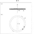
図10は、回転固定部24の構成例を示す図であり、(a)は断面図であり、(b)は平面図である。図10の(a)及び(b)に示すように、回転固定部24の底部には、回転固定部24を回転軸Axの周りを回転させるために作業者が把持する把持部24cが設けられていても構わない。これにより、作業者は、回転固定部24を容易に回転させることが可能となる。
(回転容易化機構)
図10は、回転固定部24の構成例を示す図であり、(a)は断面図であり、(b)は平面図である。図10の(a)及び(b)に示すように、回転固定部24の底部には、回転固定部24を回転軸Axの周りを回転させるために作業者が把持する把持部24cが設けられていても構わない。これにより、作業者は、回転固定部24を容易に回転させることが可能となる。
また、作業者による回転固定部24の回転方向(移動方向)の確認を容易にするために、回転固定部24の底部には、回転方向を示す刻印、シール又はイラストが付されていても構わない。図10の(b)では、「開ける←→閉める」という文字が付されている。
(緩み止め機構)
本体支持部21は、取付状態において、回転固定部24を固定する固定部(緩み止め機構)を備えていても構わない。固定部を備えることで、取付状態における回転固定部24の緩みを防止できる。固定部を備える本体支持部21及び21Aとして、図11~図13に示すような機構を例示できる。
本体支持部21は、取付状態において、回転固定部24を固定する固定部(緩み止め機構)を備えていても構わない。固定部を備えることで、取付状態における回転固定部24の緩みを防止できる。固定部を備える本体支持部21及び21Aとして、図11~図13に示すような機構を例示できる。
図11は、締め付け部26(固定部)を含む本体支持部21の構成例を示す図であり、(a)は締め付け部26の装着前の状態を示す図であり、(b)は締め付け部26の装着後の状態を示す図であり、(c)は、(b)の状態を示す断面図である。
締め付け部26は、図11の(c)に示すように、回転固定部24の直径を内径とする環状部材であり、その内壁には、回転固定部24に設けられたねじ溝24aと同ピッチのねじ溝26aが設けられたナットである。図11の(a)に示すように、回転固定部24の締め付けが完了した後(回転固定部24がシーリングローゼット本体部12の底部12aと接触した後)、締め付け部26を回転固定部24の下方から回転固定部24に嵌合する。そして、図11の(b)及び(c)に示すように、締め付け部26を内壁部21dに接触するまで締め付ける。
つまり、内壁部21d及び締め付け部26は、ダブルナットとして機能する。そのため、締め付け部26の締め付けにより、取付状態における回転固定部24の緩みを防止できる。
なお、上記固定部は、図12のような構造で実現されても構わない。図12は、締め付け部26の変形例に係る締め付け部26A(固定部)を含む本体支持部21の構成例を示す図であり、締め付け部26Aの装着後の状態を示す図である。
締め付け部26Aは、回転固定部24の直径と同一の直径を有していると共に、その外周に、回転固定部24のねじ溝24aと同一のピッチを有するねじ溝26aaが設けられている。つまり、締め付け部26Aは、回転固定部24と同様、内壁部21dへのねじ込みが可能である。回転固定部24の締め付けが完了した後、締め付け部26Aを回転固定部24の下方から内壁部21dにねじ込むことで、回転固定部24の緩み止めが防止される。つまり、回転固定部24及び締め付け部26Aが内壁部21dにねじ込まれることにより、ダブルナットと同様の効果が得られるため、回転固定部24の緩み止めを抑制できる。
また、図13は、本体支持部21及び回転固定部24の変形例である本体支持部21A(取付器具)及び回転固定部24A(支持部、回転部材)の構成例を示す図である。図13の(a)は回転固定部24Aの斜視図であり、(b)はレバー部27(固定部、爪部)による固定前の状態を示す図であり、(c)はレバー部27による固定後の状態を示す図である。
図13の(a)に示すように、回転固定部24Aは、切り欠き部24Aaを有している。切り欠き部24Aaは、回転固定部24Aの外縁部に、周方向に沿って複数設けられている。
また、図13の(b)及び(c)に示すように、本体支持部21Aは、内壁部21dに嵌合された回転固定部24Aの切り欠き部24Aaにその一部が嵌合されるレバー部27を備えている。レバー部27は、内壁部21dに設けられた貫通孔(不図示)を貫通可能に設けられている。
図13の(b)は、本体支持部21Aがねじ23によりシーリングローゼット12Aに固定されている状態であって、回転固定部24Aの締め付け前の状態である。この状態において、レバー部27の少なくとも一部は、内壁部21dの外側に位置している。レバー部27は、回転固定部24Aの移動を妨げない位置に退避していればよい。また、レバー部27は、内壁部21dに沿って複数箇所に設けられていても構わない。
その後、回転固定部24Aの締め付けの完了時において、作業者は、切り欠き部24Aaをレバー部27と対向させるように回転固定部24Aを回転させる。つまり、切り欠き部24Aaとレバー部27との位置合わせを行う。図13の(c)に示すように、切り欠き部24Aaをレバー部27と対向させた状態において、作業者は、レバー部27を本体支持部21Aの中心方向へ移動させることで、当該切り欠き部24Aaにレバー部27を嵌合する。これにより、取付状態において、回転固定部24Aを回転させようとする力が回転固定部24Aに印加されたとしても、レバー部27が切り欠き部24Aaに接触するので、回転固定部24Aの回転は阻止される。そのため、取付状態における回転固定部24Aの回転を防止できる。つまり、取付状態における回転固定部24Aの緩みを防止できる。
(締め過ぎ防止機構)
その他、本体支持部21は、回転固定部24の締め過ぎを防止する機構を備えていても構わない。当該機構としては、例えば、回転固定部24に所定のトルク以上のトルクが印加された場合に回転固定部24を空回りさせる機構が挙げられる。
その他、本体支持部21は、回転固定部24の締め過ぎを防止する機構を備えていても構わない。当該機構としては、例えば、回転固定部24に所定のトルク以上のトルクが印加された場合に回転固定部24を空回りさせる機構が挙げられる。
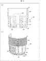
上記機構の一例について、図14及び図15を用いて説明する。図14の(a)は、回転固定部24に取り付けられたトルクスプリッタ100の一例を示す断面図であり、(b)は、トルクスプリッタ100の部分斜視図である。図15の(a)及び(b)は、トルクスプリッタ100の分解斜視図である。
なお、図14の(b)では、外ケース104の一部を取り外した状態(つまり、トルクスプリッタ100の内部構造の一部)が図示されている。また、図15の(a)は、トルクスプリッタ100を斜め上方向から見た図であり、(b)は、トルクスプリッタ100を斜め下方向から見た図である。
図14の(a)及び(b)、並びに、図15の(a)及び(b)に示すように、トルクスプリッタ100は、ばね固定部101、ばね102、内部ラチェット機構103、及び外ケース104を備えている。なお本例では、図14の(a)、並びに、図15の(a)及び(b)に示すように、回転固定部24の中央部には、ねじ200を貫通する貫通孔が設けられている。
トルクスプリッタ100は、ねじ200によって回転固定部24と固定される。具体的には、ねじ200は、回転固定部24と内部ラチェット機構103とを固定する。これにより、所定のトルクが印加されるまでは、トルクスプリッタ100の回転に連動して、回転固定部24が回転する。
ばね固定部101は、その中央部において、内部ラチェット機構103と共に、ばね102を固定する。また、ばね固定部101は、外ケース104に連結されている。これにより、外ケース104を回転させることで、ばね固定部101は、外ケース104に連動して回転する。
ばね102は、ばね固定部101と内部ラチェット機構103との間に設けられる。これにより、ばね102の力によって、内部ラチェット機構103の底部の外壁に形成されたラチェット部103aと、外ケース104の底部の内壁に形成されたラチェット部104aとが噛合位置EPで接触する(噛み合う)。
ラチェット部103a及びラチェット部104aは、複数の凹部及び凸部を有する凹凸部(例:鋸歯状の凹凸部)を有する。ラチェット部103a及びラチェット部104aのうちのいずれか一方は、傾斜した状態で立設した凸部を有しており、他方は、垂直に立設した(上方向又は下方向に延伸した)凸部を有している。本例では、ラチェット部103aが垂直に立設した凸部を有し、ラチェット部104aが傾斜した状態で立設した凸部を有するものとして説明する。
ばね102は、ばね固定部101と内部ラチェット機構103とが接触するように設けられている。そのため、外ケース104を回転させることでばね固定部101が回転すると、所定のトルク未満の場合には、内部ラチェット機構103が回転する。ラチェット部103aの凸部がラチェット部104aの凸部の斜面を乗り超える力(乗り上げる力)が小さいため、当該斜面を乗り越えらないためである。この場合、内部ラチェット機構103の回転に連動して、回転固定部24が回転する。その後、回転固定部24がシーリングローゼット本体部12の底部12aに接触すると、所定のトルクに達する。そのため、それ以降に外ケース104を回転させると、ラチェット部103aの凸部がラチェット部104aの凸部の斜面を乗り超えることにより、内部ラチェット機構103は回転せずに外ケース104が空回りする。これにより、回転固定部24を締め付けてしまうことを防止できる。
なお、ばね102の応力が大きいほど、ラチェット部103aの凸部がラチェット部104aの凸部の斜面を乗り上げる力も大きくなる。つまり、ばね102の応力を大きくするほど、より高いトルクで内部ラチェット機構103を回転させることができ、ひいては内部ラチェット機構103に連結している回転固定部24をより高いトルクで締め付けることができる。従って、所定のトルクは、例えば実験等により、回転固定部24を締め付け過ぎない(例:回転固定部24又はシーリングローゼット12Aを破壊しない)程度にばね102の応力を調整することで設定される。所定のトルクとしては、例えば、回転固定部24がシーリングローゼット本体部12の底部12aに接触したときに印加される値が設定されていればよい。
(締め付けの自動化)
また、回転固定部24の締め付けにおける安全性を考慮すれば、回転固定部24の回転は自動化されても構わない。この場合例えば、回転固定部24の軸部に、回転固定部24を回転軸Axの周りに回転させる駆動部(例:モータ)が接続されていても構わない。作業者は、例えばリモートコントローラを用いて駆動部を制御することで、回転固定部24の回転(つまり上下方向の移動)を制御しても構わない。
また、回転固定部24の締め付けにおける安全性を考慮すれば、回転固定部24の回転は自動化されても構わない。この場合例えば、回転固定部24の軸部に、回転固定部24を回転軸Axの周りに回転させる駆動部(例:モータ)が接続されていても構わない。作業者は、例えばリモートコントローラを用いて駆動部を制御することで、回転固定部24の回転(つまり上下方向の移動)を制御しても構わない。
<LEDの配置例>
なお、LED70の光出射方向は任意に設定されてよい。図16の(a)~(c)は、LED70の配置例を示す図である。図16の(a)~(c)は、本体部22を上方から見たときの、LED70の配置付近の拡大図である。
なお、LED70の光出射方向は任意に設定されてよい。図16の(a)~(c)は、LED70の配置例を示す図である。図16の(a)~(c)は、本体部22を上方から見たときの、LED70の配置付近の拡大図である。
図3の(a)を用いて説明したように、照明基板55には複数のLED70が設けられている。図16の(a)~(c)に示すように、少なくともそのうちの一部については、光出射方向が略水平方向(上下方向と略垂直な方向)を向くように配置されている。また、LED70から発せられる光が形成する投影像は略円形である。
上記光の照射範囲IAを広くしたい場合、例えば以下の3つの手法が考えられる。
・LED70と照明カバー56(LED70から発せられた光が照射される被照射部品)との距離を大きくする。
・より多くのLED70を設ける。
・LED70と照明カバー56との間に光学部材(例:レンズ)を設ける。
・LED70と照明カバー56(LED70から発せられた光が照射される被照射部品)との距離を大きくする。
・より多くのLED70を設ける。
・LED70と照明カバー56との間に光学部材(例:レンズ)を設ける。
例えば、図16の(a)に示すように、LED70の光軸Ax10が照明カバー56に対して略垂直となるように、LED70が設けられている場合を考える。この場合、図16の(b)に示すように、図16の(a)に示すLED70の配置位置P1よりも照明カバー56から離れた配置位置P2にLED70を移動させれば、図16の(a)の場合よりも照射範囲IAを広げることができる。
しかし、LED70の光出射方向には部品を搭載することはできない。図16の(b)の場合、図16の(a)の場合に比べ、LED70を本体部22のより内部に配置することになるため、図16の(a)の場合よりも部品を搭載できない範囲が増加する。そのため、スペース効率が低下する。また、図16の(b)の場合、部品を搭載するために、LED70が配置された照明基板55自体の配置位置を変更する等の手間が生じる可能性もある。
図16の(c)では、配置位置P1において、LED70の光軸Ax10が照明カバー56と略垂直方向とは異なる方向を向くように(つまり斜め方向を向くように)、LED70を配置している。本例では、隣接する2個のLED70の光軸Ax10が互いに向かい合う方向を向くように、LED70が配置されている。
一般に、照明基板55上のLED70は、その製法上又は精度管理上、斜め方向を向くように取り付けられることは少ない。一方で、各LED70から発せられる光の照射範囲の境目は曖昧であるため、LED70を斜めに取り付けたとしても、生産技術上の実害はほとんどない。
従って、LED70を斜めに取り付けるという単純なレイアウトの変更で、LED70の配置位置を変更することなく(配置位置P1のまま)、図16の(b)と同様、幅広い照射範囲IAに光を照射できる。図16の(c)に示すようにLED70を配置することで、以下のような効果を奏することができる。
・配置位置P1を変更することが無いので、スペース効率を向上させることができる。
・照射範囲IAを広げるための光学部品も不要となる。また、LED70を増加させる必要もない。
・2つのLED70の前方かつ中央付近が明るく、中央付近から離れるに従い暗くなるといった、自然な光を照射できる。
・LED70を正面から見たときにLED70自体を視認しにくい。
・配置位置P1を変更することが無いので、スペース効率を向上させることができる。
・照射範囲IAを広げるための光学部品も不要となる。また、LED70を増加させる必要もない。
・2つのLED70の前方かつ中央付近が明るく、中央付近から離れるに従い暗くなるといった、自然な光を照射できる。
・LED70を正面から見たときにLED70自体を視認しにくい。
〔実施形態2〕
本発明の他の実施形態について、以下に説明する。なお、説明の便宜上、上記実施形態にて説明した部材と同じ機能を有する部材については、同じ符号を付記し、その説明を繰り返さない。
本発明の他の実施形態について、以下に説明する。なお、説明の便宜上、上記実施形態にて説明した部材と同じ機能を有する部材については、同じ符号を付記し、その説明を繰り返さない。
<本体支持部の詳細>
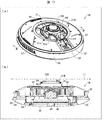
図17の(a)は、送風装置1Bの斜視図であり、(b)は、送風装置1BのB-B’断面図である。図17の(a)及び(b)は、送風装置1Bが天井パネル11に取り付けられた状態(取付状態)を示している。送風装置1Bの基本的な構成は送風装置1と同様であるが、送風装置1Bは、本体支持部21に代えて本体支持部21B(取付器具)を備えた点で、送風装置1とは異なる。
図17の(a)は、送風装置1Bの斜視図であり、(b)は、送風装置1BのB-B’断面図である。図17の(a)及び(b)は、送風装置1Bが天井パネル11に取り付けられた状態(取付状態)を示している。送風装置1Bの基本的な構成は送風装置1と同様であるが、送風装置1Bは、本体支持部21に代えて本体支持部21B(取付器具)を備えた点で、送風装置1とは異なる。
具体的には、図17の(a)及び(b)に示すように、本体支持部21Bは、第1孔部25を介してシーリングローゼット12Bのシーリングローゼット本体部12を支持する支持部として、回転固定部24に代えて支持板84(支持部)を備えている。また、支持板84を上下方向に沿って移動させるためのばね85(伸縮部材)を備えている。
なお、本実施形態のシーリングローゼット12Bは、後述の図21の(a)及び(b)に示すように、シーリングローゼット本体部12の底部にローゼットカバー12bを備える点で、実施形態1のシーリングローゼット12Aとは異なる。ローゼットカバー12bは、シーリングローゼット本体部12を覆うものである。ローゼットカバー12bの外縁部の2箇所にハンガー部13が接続されている。ローゼットカバー12bとハンガー部13とは一体に設けられていてもよいし、別体に設けられていてもよい。また、本実施形態においてシーリングローゼット12Aを用いても構わないし、実施形態1においてシーリングローゼット12Bを用いても構わない。
図18は、本体支持部21Bの断面図である。図19は、支持板84の構成例を示す図であり、(a)は平面図及び側面図であり、(b)は斜視図である。
支持板84は、図18に示すように、第1孔部25を介してシーリングローゼット本体部12と接触する接触部84aと、接触部84aから突出した突出部84bと、を備えている。
本体支持部21Bの円筒部21b(側壁)には、第2孔部21gが設けられている。第2孔部21gには、突出部84bが貫通して設けられている。第2孔部21gは、突出部84bの上下方向の移動を可能にするように、少なくとも突出部84bの移動量の分、上下方向に開口している。
第2孔部21gから突出した突出部84bの一部(例:端部)には、上下方向に沿って伸縮するばね85が設けられている。ばね85は、突出部84bの一部と、下板部21cの一部とに接続されている。ばね85の接続により、突出部84b及び下板部21cには相対的に離れる方向に力が印加される。そして、ばね85の伸縮により、支持板84は、上下方向に移動可能となる。つまり、ばね85は、支持板84が上下方向に移動可能なように支持板84を保持している。
図19の(a)及び(b)に示すように、接触部84aは、第1孔部25を貫通可能で、かつ、第1孔部25の内径(つまりローゼットカバー12b(底部)の内径)と略同一の直径を有する円形状の板部である。この場合、ローゼットカバー12bの略全面を接触部84aで支持できるので、取付状態において、本体部22をシーリングローゼット12Bに安定して固定できる。但し、接触部84aの形状及び大きさはこれに限らず、第1孔部25を貫通可能で、かつ、シーリングローゼット本体部12を支持可能な形状及び大きさであればよい。
突出部84bは、接触部84aの外縁部の、互いに対向する位置(2箇所)に設けられている。突出部84bが設けられる位置は、支持板84が本体支持部21Bに設けられたときに、第2孔部21gから突出される位置に設けられていればよい。また、本実施形態では、2箇所に設けられているが、その個数も問わない。接触部84aがローゼットカバー12bに接触したときに、接触部84aが安定して上下方向に移動できる程度に設けられていればよい。突出部84bの個数及び配置位置にあわせて、第2孔部21gの個数及び形成位置、並びに、ばね85の個数及び配置位置が決定される。
支持板84は、更に、接触部84aが第1孔部25から過剰に突出することを防止する突出防止部84cを備える。突出防止部84cは、接触部84aの外縁部の、互いに対向する位置(2箇所)(但し、突出部84bが設けられていない位置)に設けられている。ばね85による接触部84aの過剰な突出を安定して防止できるのであれば、突出防止部84cの個数及び配置位置は、上記個数及び配置位置に限られない。
図20は、支持板84及びばね85が取り付けられた本体支持部21Bの構成例を示す図であり、(a)は平面図及び側面図であり、(b)は斜視図である。図20の(b)に示すように、接触部84aは、シーリングローゼット本体部12を支持し易くするために、第1孔部25から僅かに突出して設けられている。図20の(a)及び(b)に示すように、突出防止部84cが上板部21a(裏側)と接触することで、接触部84aの第1孔部25からの突出量が規定されている。また、図20の(a)及び(b)に示すように、ばね85は、上述の通り、下板部21cの一部と突出部84bの端部とに接続されている。
なお、ばね85は、支持板84と本体部22との間に設けられていればよい。実施形態1と同様、本体部22は、支持部材嵌合部31に嵌合させた後、嵌合凸部31aを嵌合孔21fに嵌合させることで、本体支持部21Bに取り付けられる。この状態では、本体支持部21Bと本体部22とは一体化している。そのため、例えば、ばね85の一端を本体部22の一部に設けた場合であっても、ばね85は、下板部21cに取り付けた場合と同様の機能を発揮できる。また、ばね85の一端を支持部材嵌合部31の一部に設けても構わない。但し、この場合、一体化した本体支持部21Bと本体部22とをシーリングローゼット12Bに取り付けることになる。そのため、取り付けの容易性又は安全性等を考慮すれば、ばね85の一端は下板部21cに設けられることが好ましい。
また、上下方向に伸縮する伸縮部材としてばね85を用いる例を挙げて説明しているが、支持板84を上下方向に移動させる部材であれば、ばね85以外の部材(例:ゴム、樹脂又は熱可塑性エラストマー等の弾性部材)であっても構わない。
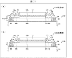
図21は、取付状態を示す図である。図21の(a)は、段差Dが存在するシーリングローゼット12Bに本体支持部21Bが取り付けられた状態を示す図であり、(b)は、段差Dが存在しないシーリングローゼット12Bに本体支持部21Bが取り付けられた状態を示す図である。
まず、図21の(a)に示すように、ローゼットカバー12bとハンガー接触部13aとの間に段差Dが存在する場合について説明する。段差Dを有するシーリングローゼット12Bに本体支持部21Bが取り付けられる場合、まず、接触部84aがローゼットカバー12bに接触する。段差Dが存在するため、この接触状態においては、上板部21aとハンガー接触部13aとは接触していない。この接触状態においてねじ23を締め付けていくと、支持板84がばね85に接続されているため、支持板84が押し下げられ、シーリングローゼット本体部12が第1孔部25に挿入されていく。その結果、上板部21aとハンガー接触部13aとが接触するまで(段差Dに起因した隙間がなくなるまで)ねじ23を締め付けることができる。
図21の(b)に示すように、ローゼットカバー12bとハンガー接触部13aとの間に段差Dが存在しない場合、接触部84aがローゼットカバー12bに接触したときに、上板部21aとハンガー接触部13aとの間に僅かな隙間が生じる。上述したように、接触部84aが第1孔部25から僅かに突出しているためである。この場合であっても、図21の(a)と同様、ねじ23を締め付けていくと、ばね85により、支持板84が押し下げられ、シーリングローゼット本体部12が第1孔部25に挿入されていく。その結果、上板部21aとハンガー接触部13aとが接触するまでねじ23を締め付けることができる。但し、図21の(a)の場合よりも支持板84の移動量(ばね85の縮み量)は小さい。
このように、ばね85が支持板84と本体部22(具体的には本体支持部21Bの下板部21c)との間に設けられている。そのため、実施形態1と同様、シーリングローゼット12Bの形状に依らず、本体支持部21Bをシーリングローゼット12Bに安定して、かつ簡易に固定できる。加えて、支持板84をばね85で支持しているので、地震等による揺れが発生した場合でも、本体部22の揺れを抑制できる。つまり、取付状態の送風装置1Bの耐震性を向上させることができる。
〔まとめ〕
本発明の態様1に係る取付器具は、シーリングローゼットに電気機器を取り付けるための取付器具であって、前記シーリングローゼットのシーリングローゼット本体部が貫通可能な第1孔部と、前記第1孔部を介して前記シーリングローゼット本体部を支持する支持部と、を備え、前記支持部は、前記シーリングローゼット本体部の前記第1孔部への挿入方向又はその逆方向に沿って移動可能である。
本発明の態様1に係る取付器具は、シーリングローゼットに電気機器を取り付けるための取付器具であって、前記シーリングローゼットのシーリングローゼット本体部が貫通可能な第1孔部と、前記第1孔部を介して前記シーリングローゼット本体部を支持する支持部と、を備え、前記支持部は、前記シーリングローゼット本体部の前記第1孔部への挿入方向又はその逆方向に沿って移動可能である。
本発明の態様2に係る取付器具は、態様1において、前記支持部は、前記第1孔部に嵌合されることにより、前記シーリングローゼット本体部の底部を支持しても構わない。
本発明の態様3に係る取付器具は、態様2において、前記支持部、及び前記第1孔部を規定する前記取付器具の内壁部のそれぞれにねじ溝が設けられ、前記支持部は、前記内壁部に対して回転する回転部材であっても構わない。
本発明の態様4に係る取付器具は、態様1から3の何れかにおいて、前記支持部により前記シーリングローゼット本体部が支持されることで、前記シーリングローゼットに前記取付器具が取り付けられた取付状態において、前記支持部を固定する固定部を備えても構わない。
本発明の態様5に係る取付器具は、態様1において、前記挿入方向又はその逆方向に沿って伸縮する伸縮部材を備え、前記伸縮部材は、前記支持部と前記電気機器の本体部との間に設けられていても構わない。
本発明の態様6に係る取付器具は、態様5において、前記電気機器の本体部と対向する下板部を備え、前記支持部は、前記第1孔部を介して前記シーリングローゼット本体部と接触する接触部と、前記接触部から突出した突出部と、を備え、前記取付器具の側壁には、前記突出部が貫通し、かつ前記突出部の前記挿入方向又はその逆方向への移動を可能にする第2孔部が設けられ、前記伸縮部材は、前記第2孔部から突出した前記突出部の一部と、前記下板部の一部とに接続されていても構わない。
本発明の態様7に係る電気機器は、前記シーリングローゼットに取り付けられる前記電気機器であって、態様1から6の何れかに記載の取付器具を備える。
〔付記事項〕
本発明は上述した各実施形態に限定されるものではなく、請求項に示した範囲で種々の変更が可能であり、異なる実施形態にそれぞれ開示された技術的手段を適宜組み合わせて得られる実施形態についても本発明の技術的範囲に含まれる。さらに、各実施形態にそれぞれ開示された技術的手段を組み合わせることにより、新しい技術的特徴を形成することができる。
本発明は上述した各実施形態に限定されるものではなく、請求項に示した範囲で種々の変更が可能であり、異なる実施形態にそれぞれ開示された技術的手段を適宜組み合わせて得られる実施形態についても本発明の技術的範囲に含まれる。さらに、各実施形態にそれぞれ開示された技術的手段を組み合わせることにより、新しい技術的特徴を形成することができる。
1、1B 送風装置(電気機器)
12 シーリングローゼット本体部
12A、12B シーリングローゼット
12a 底部
12b ローゼットカバー(底部)
21、21’、21A、21B 本体支持部(取付器具)
21b 円筒部(側壁)
21c 下板部
21d 内壁部
21g 第2孔部
21da ねじ溝
22 本体部
24、24A 回転固定部(支持部、回転部材)
24’ 支持部
24a ねじ溝
25 第1孔部
26 締め付け部(固定部)
26A 締め付け部(固定部)
27 レバー部(固定部)
84 支持板(支持部)
84a 接触部
84b 突出部
85 ばね(伸縮部材)
12 シーリングローゼット本体部
12A、12B シーリングローゼット
12a 底部
12b ローゼットカバー(底部)
21、21’、21A、21B 本体支持部(取付器具)
21b 円筒部(側壁)
21c 下板部
21d 内壁部
21g 第2孔部
21da ねじ溝
22 本体部
24、24A 回転固定部(支持部、回転部材)
24’ 支持部
24a ねじ溝
25 第1孔部
26 締め付け部(固定部)
26A 締め付け部(固定部)
27 レバー部(固定部)
84 支持板(支持部)
84a 接触部
84b 突出部
85 ばね(伸縮部材)
Claims (7)
- シーリングローゼットに電気機器を取り付けるための取付器具であって、
前記シーリングローゼットのシーリングローゼット本体部が貫通可能な第1孔部と、
前記第1孔部を介して前記シーリングローゼット本体部を支持する支持部と、を備え、
前記支持部は、前記シーリングローゼット本体部の前記第1孔部への挿入方向又はその逆方向に沿って移動可能である、取付器具。 - 前記支持部は、前記第1孔部に嵌合されることにより、前記シーリングローゼット本体部の底部を支持する、請求項1に記載の取付器具。
- 前記支持部、及び前記第1孔部を規定する前記取付器具の内壁部のそれぞれにねじ溝が設けられ、
前記支持部は、前記内壁部に対して回転する回転部材である、請求項2に記載の取付器具。 - 前記支持部により前記シーリングローゼット本体部が支持されることで、前記シーリングローゼットに前記取付器具が取り付けられた取付状態において、前記支持部を固定する固定部を備える、請求項1から3の何れか1項に記載の取付器具。
- 前記挿入方向又はその逆方向に沿って伸縮する伸縮部材を備え、
前記伸縮部材は、前記支持部と前記電気機器の本体部との間に設けられている、請求項1に記載の取付器具。 - 前記電気機器の本体部と対向する下板部を備え、
前記支持部は、
前記第1孔部を介して前記シーリングローゼット本体部と接触する接触部と、
前記接触部から突出した突出部と、を備え、
前記取付器具の側壁には、前記突出部が貫通し、かつ前記突出部の前記挿入方向又はその逆方向への移動を可能にする第2孔部が設けられ、
前記伸縮部材は、前記第2孔部から突出した前記突出部の一部と、前記下板部の一部とに接続されている、請求項5に記載の取付器具。 - 前記シーリングローゼットに取り付けられる前記電気機器であって、
請求項1から6の何れか1項に記載の取付器具を備える、電気機器。
Priority Applications (1)
| Application Number | Priority Date | Filing Date | Title |
|---|---|---|---|
| JP2020527197A JP7150844B2 (ja) | 2018-06-25 | 2019-02-27 | 取付器具、及び電気機器 |
Applications Claiming Priority (2)
| Application Number | Priority Date | Filing Date | Title |
|---|---|---|---|
| JP2018-119947 | 2018-06-25 | ||
| JP2018119947 | 2018-06-25 |
Publications (1)
| Publication Number | Publication Date |
|---|---|
| WO2020003612A1 true WO2020003612A1 (ja) | 2020-01-02 |
Family
ID=68986862
Family Applications (1)
| Application Number | Title | Priority Date | Filing Date |
|---|---|---|---|
| PCT/JP2019/007535 Ceased WO2020003612A1 (ja) | 2018-06-25 | 2019-02-27 | 取付器具、及び電気機器 |
Country Status (3)
| Country | Link |
|---|---|
| JP (1) | JP7150844B2 (ja) |
| TW (1) | TW202002442A (ja) |
| WO (1) | WO2020003612A1 (ja) |
Citations (3)
| Publication number | Priority date | Publication date | Assignee | Title |
|---|---|---|---|---|
| JPS5689109U (ja) * | 1979-12-10 | 1981-07-16 | ||
| JPH05151812A (ja) * | 1991-11-29 | 1993-06-18 | Toshiba Lighting & Technol Corp | 照明器具 |
| JPH10162632A (ja) * | 1996-12-03 | 1998-06-19 | Matsushita Electric Works Ltd | 照明器具 |
Family Cites Families (1)
| Publication number | Priority date | Publication date | Assignee | Title |
|---|---|---|---|---|
| JPS568910U (ja) * | 1979-07-02 | 1981-01-26 |
-
2019
- 2019-02-27 JP JP2020527197A patent/JP7150844B2/ja active Active
- 2019-02-27 WO PCT/JP2019/007535 patent/WO2020003612A1/ja not_active Ceased
- 2019-06-25 TW TW108122174A patent/TW202002442A/zh unknown
Patent Citations (3)
| Publication number | Priority date | Publication date | Assignee | Title |
|---|---|---|---|---|
| JPS5689109U (ja) * | 1979-12-10 | 1981-07-16 | ||
| JPH05151812A (ja) * | 1991-11-29 | 1993-06-18 | Toshiba Lighting & Technol Corp | 照明器具 |
| JPH10162632A (ja) * | 1996-12-03 | 1998-06-19 | Matsushita Electric Works Ltd | 照明器具 |
Also Published As
| Publication number | Publication date |
|---|---|
| JPWO2020003612A1 (ja) | 2021-08-05 |
| JP7150844B2 (ja) | 2022-10-11 |
| TW202002442A (zh) | 2020-01-01 |
Similar Documents
| Publication | Publication Date | Title |
|---|---|---|
| JP4352230B2 (ja) | 天井埋込形照明器具 | |
| US9746195B2 (en) | Ceiling mounted ventilation fan | |
| US8888315B2 (en) | Vapor-tight lighting fixture | |
| US11359806B2 (en) | Ventilation system | |
| US9575395B2 (en) | Ceiling hanger | |
| US7874711B2 (en) | Surface-mounted lighting system | |
| JP2018097923A (ja) | 照明器具 | |
| JP5552563B1 (ja) | Led照明装置 | |
| JP6601665B2 (ja) | 照明器具 | |
| JP7150844B2 (ja) | 取付器具、及び電気機器 | |
| JP2022168083A (ja) | 灯具 | |
| JP6508473B2 (ja) | 照明器具 | |
| JP4793728B2 (ja) | 配線器具 | |
| KR20150127909A (ko) | 평판조명 | |
| JP2022054170A (ja) | 取付装置および照明装置 | |
| JP2018097924A (ja) | 照明器具 | |
| JP2017195044A (ja) | 灯具 | |
| KR101719055B1 (ko) | 천정등 커버 탈착장치 | |
| JP7034669B2 (ja) | 送風装置 | |
| JP5695238B2 (ja) | Led照明装置 | |
| JP6639114B2 (ja) | 照明装置 | |
| JP2016171034A (ja) | 照明装置 | |
| JP5643412B1 (ja) | Led照明装置 | |
| KR20250115154A (ko) | Led 조명 기구 | |
| JP2025101246A (ja) | センサ装置 |
Legal Events
| Date | Code | Title | Description |
|---|---|---|---|
| 121 | Ep: the epo has been informed by wipo that ep was designated in this application |
Ref document number: 19826794 Country of ref document: EP Kind code of ref document: A1 |
|
| ENP | Entry into the national phase |
Ref document number: 2020527197 Country of ref document: JP Kind code of ref document: A |
|
| NENP | Non-entry into the national phase |
Ref country code: DE |
|
| 122 | Ep: pct application non-entry in european phase |
Ref document number: 19826794 Country of ref document: EP Kind code of ref document: A1 |