WO2020003573A1 - Vibration device and optical detection device - Google Patents
Vibration device and optical detection device Download PDFInfo
- Publication number
- WO2020003573A1 WO2020003573A1 PCT/JP2019/002547 JP2019002547W WO2020003573A1 WO 2020003573 A1 WO2020003573 A1 WO 2020003573A1 JP 2019002547 W JP2019002547 W JP 2019002547W WO 2020003573 A1 WO2020003573 A1 WO 2020003573A1
- Authority
- WO
- WIPO (PCT)
- Prior art keywords
- vibration
- light transmitting
- region
- vibrating
- vibration device
- Prior art date
Links
Images


Classifications
-
- G—PHYSICS
- G03—PHOTOGRAPHY; CINEMATOGRAPHY; ANALOGOUS TECHNIQUES USING WAVES OTHER THAN OPTICAL WAVES; ELECTROGRAPHY; HOLOGRAPHY
- G03B—APPARATUS OR ARRANGEMENTS FOR TAKING PHOTOGRAPHS OR FOR PROJECTING OR VIEWING THEM; APPARATUS OR ARRANGEMENTS EMPLOYING ANALOGOUS TECHNIQUES USING WAVES OTHER THAN OPTICAL WAVES; ACCESSORIES THEREFOR
- G03B17/00—Details of cameras or camera bodies; Accessories therefor
- G03B17/56—Accessories
-
- G—PHYSICS
- G02—OPTICS
- G02B—OPTICAL ELEMENTS, SYSTEMS OR APPARATUS
- G02B27/00—Optical systems or apparatus not provided for by any of the groups G02B1/00 - G02B26/00, G02B30/00
- G02B27/0006—Optical systems or apparatus not provided for by any of the groups G02B1/00 - G02B26/00, G02B30/00 with means to keep optical surfaces clean, e.g. by preventing or removing dirt, stains, contamination, condensation
-
- G—PHYSICS
- G02—OPTICS
- G02B—OPTICAL ELEMENTS, SYSTEMS OR APPARATUS
- G02B27/00—Optical systems or apparatus not provided for by any of the groups G02B1/00 - G02B26/00, G02B30/00
- G02B27/64—Imaging systems using optical elements for stabilisation of the lateral and angular position of the image
- G02B27/646—Imaging systems using optical elements for stabilisation of the lateral and angular position of the image compensating for small deviations, e.g. due to vibration or shake
-
- G—PHYSICS
- G03—PHOTOGRAPHY; CINEMATOGRAPHY; ANALOGOUS TECHNIQUES USING WAVES OTHER THAN OPTICAL WAVES; ELECTROGRAPHY; HOLOGRAPHY
- G03B—APPARATUS OR ARRANGEMENTS FOR TAKING PHOTOGRAPHS OR FOR PROJECTING OR VIEWING THEM; APPARATUS OR ARRANGEMENTS EMPLOYING ANALOGOUS TECHNIQUES USING WAVES OTHER THAN OPTICAL WAVES; ACCESSORIES THEREFOR
- G03B15/00—Special procedures for taking photographs; Apparatus therefor
-
- H—ELECTRICITY
- H04—ELECTRIC COMMUNICATION TECHNIQUE
- H04N—PICTORIAL COMMUNICATION, e.g. TELEVISION
- H04N23/00—Cameras or camera modules comprising electronic image sensors; Control thereof
-
- G—PHYSICS
- G03—PHOTOGRAPHY; CINEMATOGRAPHY; ANALOGOUS TECHNIQUES USING WAVES OTHER THAN OPTICAL WAVES; ELECTROGRAPHY; HOLOGRAPHY
- G03B—APPARATUS OR ARRANGEMENTS FOR TAKING PHOTOGRAPHS OR FOR PROJECTING OR VIEWING THEM; APPARATUS OR ARRANGEMENTS EMPLOYING ANALOGOUS TECHNIQUES USING WAVES OTHER THAN OPTICAL WAVES; ACCESSORIES THEREFOR
- G03B2205/00—Adjustment of optical system relative to image or object surface other than for focusing
- G03B2205/0053—Driving means for the movement of one or more optical element
- G03B2205/0061—Driving means for the movement of one or more optical element using piezoelectric actuators
-
- G—PHYSICS
- G03—PHOTOGRAPHY; CINEMATOGRAPHY; ANALOGOUS TECHNIQUES USING WAVES OTHER THAN OPTICAL WAVES; ELECTROGRAPHY; HOLOGRAPHY
- G03B—APPARATUS OR ARRANGEMENTS FOR TAKING PHOTOGRAPHS OR FOR PROJECTING OR VIEWING THEM; APPARATUS OR ARRANGEMENTS EMPLOYING ANALOGOUS TECHNIQUES USING WAVES OTHER THAN OPTICAL WAVES; ACCESSORIES THEREFOR
- G03B2205/00—Adjustment of optical system relative to image or object surface other than for focusing
- G03B2205/0053—Driving means for the movement of one or more optical element
- G03B2205/0069—Driving means for the movement of one or more optical element using electromagnetic actuators, e.g. voice coils
Definitions
- the present invention relates to a vibration device and an optical detection device capable of removing water droplets and the like by mechanical vibration.
- Patent Literature 1 discloses a vibration device having a light-transmitting portion disposed in front of a camera body. In this vibrating device, water droplets adhering to the light transmitting portion are atomized by vibrating the light transmitting portion largely. Patent Literature 1 describes that a water droplet can be moved to a hydrophilic portion side by forming a hydrophilic portion other than a region to be photographed.
- antinodes of vibration and nodes of vibration are formed in a portion of the translucent portion located in the visual field region of the camera body.
- the water droplet moves toward the antinode of the vibration, and the water droplet is atomized near the antinode of the vibration.
- the water droplet located at the node of the vibration is hard to move toward the antinode of the vibration. For this reason, water droplets may remain and the field of view of the camera body may be obstructed.
- An object of the present invention is to provide a vibration device and an optical detection device that can more reliably secure a detection area of an optical detection element.
- the vibration device includes a light-transmitting member disposed so as to include at least a part of the detection region of the optical detection element, and a vibration element having a vibration member connected to the light-transmitting member,
- the light-transmitting member has a central region and a peripheral region located around the central region, and a hydrophilic film is provided on the peripheral region of the light-transmitting member.
- the optical detection device includes a vibration device configured according to the present invention, and an optical detection element arranged so that the light transmitting body includes a detection region.
- FIG. 1 is a schematic perspective view of an imaging device having the vibration device according to the first embodiment.
- FIG. 2 is a schematic front sectional view of an imaging device having the vibration device according to the first embodiment of the present invention.
- FIG. 3 is a schematic perspective view of the piezoelectric vibrator according to the first embodiment of the present invention.
- FIG. 4 is a schematic diagram for explaining each vibration mode.
- FIGS. 5A to 5C are schematic perspective views for explaining examples of the polarization structure of the piezoelectric body in the first embodiment.
- FIG. 6 is a plan view of a vibration device according to a second embodiment of the present invention.
- FIG. 7 is a schematic front sectional view of a vibration device according to a third embodiment of the present invention.
- FIG. 8 is a schematic cross-sectional view for explaining a second vibration mode in the third embodiment of the present invention.
- FIG. 1 is a schematic perspective view of an imaging device having the vibration device according to the first embodiment.
- FIG. 2 is a schematic front sectional view of an imaging device having the vibration device according to the first embodiment.
- a control unit described later may be omitted.
- the vibrating device 1 is a vibrating device that removes water droplets and foreign matter from the field of view of the image sensor by moving water droplets and foreign matter by vibration, or atomizing the water droplets and the like.
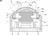
- the vibration device 1 includes a vibration element 2 including a cylindrical vibration body 3, a light transmitting body 4 provided to cover an opening of the vibration element 2, and an electric And a control unit 12 that is electrically connected.
- the imaging device 10 has a cylindrical case member 13 that supports the vibration device 1 at one end, and a base member 14 that is fixed to the other end of the case member 13.
- An image sensor 10A is arranged in an internal space surrounded by the vibration device 1, the case member 13, and the base member 14. Thereby, an imaging device 10 as an optical detection device according to one embodiment of the present invention is configured.
- the imaging element 10A for example, a CMOS, a CCD, a bolometer, a thermopile, or the like that receives light of any wavelength from the visible region to the far infrared region can be used.
- the imaging device 10 include a camera, a Radar and a LIDAR device, and the like.
- the case member 13 is fixed on the base member 14.
- a plurality of legs 15 are fixed on the base member 14.
- a board 16 is fixed on the plurality of legs 15.
- the image sensor 10A is fixed on the substrate 16.
- the imaging device 10A has an imaging device body 10a and a lens module 10b. The portion on the lens module 10b side of the imaging element 10A is located in the internal space of the vibration device 1, and the remaining portion is located in the internal space of the case member 13. Note that the entire imaging element 10A may be located in the internal space of the vibration device 1.
- a circuit for driving the image sensor 10A and the control unit 12 are provided on at least one main surface of the substrate 16 or one main surface of the base member 14.
- an optical detection element other than the imaging element 10A for optically detecting an energy ray may be arranged.
- the energy ray to be detected may be, for example, an active energy ray such as an electromagnetic wave or an infrared ray.
- a field of view as a detection region of the imaging element 10 ⁇ / b> A is included in the light transmitting body 4.
- the center of the visual field is located in the central area A of the light transmitting body 4, and the peripheral area of the visual field is located in the peripheral area B of the light transmitting body 4.
- the present invention is not limited to this, and the light transmitting body 4 may be disposed so as to include at least a part of the field of view of the imaging element 10A.
- the term "light-transmitting property" in the present specification refers to a light-transmitting property at which an energy ray or light having a wavelength detected by the optical detection element is transmitted.
- the imaging device 10 shown in FIGS. 1 and 2 is an example, and the configuration of the imaging device 10 is not limited to the above.
- the imaging device 10 only needs to include the vibration device 1 and the imaging element 10A.
- the vibration element 2 has a vibration body 3 and a piezoelectric vibrator 7.
- the vibrating body 3 is substantially cylindrical and has a first open end 3a and a second open end 3b.
- the direction connecting the first open end 3a and the second open end 3b is defined as the axial direction
- the direction orthogonal to the axial direction is defined as the radial direction.
- the vibrating body 3 has an extension 3c located on the first opening end 3a side and extending radially inward.
- the light transmitting member 4 is connected to a portion of the first opening end 3a located at the extension 3c so as to cover the opening of the vibrating member 3.
- the vibrating body 3 has a hinge 3d located between the first open end 3a and the second open end 3b.
- the hinge 3d extends radially outward.
- the vibration device 1 is supported by the case member 13 at the hinge 3d.
- the thickness in the radial direction of the vibrating body 3 is a thickness
- the thickness of the portion located between the hinge 3d and the extension 3c is the thickness of the hinge 3d and the second opening end. 3b.
- the vibrating body 3 may not have the hinge portion 3d and the extension portion 3c, and the thickness of the vibrating body 3 may be the same in all portions.
- the vibrating body 3 may have a cylindrical shape.
- the vibrating body 3 may have a cylindrical shape or a rectangular cylindrical shape.
- the piezoelectric vibrator 7 is disposed at the second opening end 3 b of the vibrating body 3.
- the piezoelectric vibrator 7 vibrates the connected body of the light transmitting body 4 and the vibrating body 3.
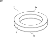
- FIG. 3 is a schematic perspective view of the piezoelectric vibrator according to the first embodiment.
- the piezoelectric vibrator 7 has an annular piezoelectric body 8.
- the piezoelectric body 8 is made of, for example, an appropriate piezoelectric ceramic such as Pb (Zr, Ti) O 3 or (K, Na) NbO 3 or an appropriate piezoelectric single crystal such as LiTaO 3 or LiNbO 3 .
- An electrode 9a is provided on one main surface of the piezoelectric body 8, and an electrode 9b is provided on the other main surface.
- one annular piezoelectric vibrator 7 is disposed on the vibrating body 3.
- the shape and the number of the piezoelectric vibrators 7 are not limited to the above.
- a plurality of piezoelectric vibrators may be arranged along a circumferential direction with the center of the vibrating body 3 as a rotation axis.
- the translucent member 4 has a dome shape in the present embodiment.
- the shape of the light transmitting body 4 is not limited to the above, and may be, for example, a disk shape.
- the light transmitting body 4 is made of a light transmitting material.
- As the translucent material for example, translucent plastic, glass, or translucent ceramics can be used.
- the light transmitting body 4 has a central area A and a peripheral area B located around the central area A.
- a water-repellent film 6 is provided in the central region A of the light transmitting body 4.
- a hydrophilic film 5 is provided in the peripheral region B of the light transmitting body 4. More specifically, the hydrophilic film 5 and the water-repellent film 6 are provided on the outer surface of the light transmitting body 4 that transmits light and energy rays into the inside of the vibration device 1.
- the material of the water-repellent film 6 include a fluorine-based material such as polytetrafluoroethylene and a silicon-based material such as a perfluoroalkyl group-containing silane.
- the material of the hydrophilic film 5 include an inorganic material such as TiO 2 and an organic material such as hydrophilic PVDF. Note that the water-repellent film 6 does not necessarily have to be provided on the translucent member 4.
- the control unit 12 is electrically connected to the vibration element 2. More specifically, the control unit 12 is electrically connected to the piezoelectric vibrator 7.
- the control unit 12 controls the vibration of the connected body of the light transmitting body 4 and the vibrating body 3 by the piezoelectric vibrator 7.
- a plurality of vibration modes may be switched by the control unit 12.
- the control unit 12 vibrates the connected body of the light transmitting body 4 and the vibrating body 3 so that the node of the vibration is located at the hinge 3d of the vibrating body 3.
- the vibration device 1 can be easily supported by the case member 13, and the sealing property of the imaging device 10 can be improved.
- the support of the case member 13 makes it difficult to hinder the vibration of the vibration device 1.
- the hydrophilic film 5 is provided in the peripheral region B of the light transmitting body 4. Thereby, the visual field of the imaging element 10A as a detection area of the optical detection element can be more reliably secured. This will be described below together with the details of the vibration mode used by the vibration device 1.
- FIG. 4 is a schematic diagram for explaining each vibration mode.
- FIG. 4 shows the phase of vibration of each region in the light transmitting body when viewed in plan.
- the region marked with a + sign and the region marked with a-sign indicate that the phases of vibration are opposite to each other.
- the vibration mode can be represented by the (m, n) mode.
- m and n are integers.
- m is the number of vibration node lines extending in the circumferential direction
- n is the number of vibration node lines extending in the radial direction.
- the (1,0) mode, the (1,1) mode, or the (1,2) mode is used.
- the line of the node of the vibration extending in the circumferential direction in the (1,0) mode, the (1,1) mode, and the (1,2) mode is located in the peripheral region B of the light transmitting body 4.
- the piezoelectric vibrator 7 of the vibration device 1 is configured to be able to excite the (1,0) mode, the (1,1) mode, or the (1,2) mode vibration in the light transmitting body 4. ing.
- the control section 12 controls the voltage or the like applied to the piezoelectric vibrator 7 to excite the (1,0) mode, (1,1) mode, or (1,2) mode vibration.
- FIGS. 5A to 5C are schematic perspective views illustrating examples of the polarization structure of the piezoelectric body according to the first embodiment.
- a region with a + sign indicates a region in which the polarization direction is from the lower surface to the upper surface in FIG. 5A of the piezoelectric body.
- a region with a minus sign indicates that the polarization direction is a direction from the upper surface to the lower surface of the piezoelectric body.
- FIGS. 5B and 5C The same applies to FIGS. 5B and 5C.
- the polarization directions of the regions arranged in the circumferential direction are all the same.
- the electrodes 9a and 9b of the piezoelectric vibrator 7 shown in FIG. 3 are annular. Therefore, when the piezoelectric body 8 having the polarization structure shown in FIG. 5A is used, the (1, 0) mode vibration is excited in the light transmitting body 4.
- FIG. 5B in the region divided into four in the circumferential direction, the polarization directions of the regions on both sides facing each other via the center are opposite.
- the piezoelectric body 8 having the polarization structure shown in FIG. 5B is used, the (1,1) mode vibration is excited in the light transmitting body 4.
- FIG. 5A the polarization directions of the regions arranged in the circumferential direction are all the same.
- the electrodes 9a and 9b of the piezoelectric vibrator 7 shown in FIG. 3 are annular. Therefore, when the piezoelectric body 8 having the polarization structure shown in FIG. 5A is used, the (1, 0
- the electrode 9a and the electrode 9b shown in FIG. 3 may be divided in the circumferential direction, and the divided electrodes may be arranged in the above-described regions of the piezoelectric body 8.
- the AC voltages having phases opposite to each other are applied to the regions on both sides facing each other with the center therebetween.
- the (1,1) mode vibration can be excited in the optical body 4.
- each vibration mode may be switched by the control unit 12.
- the antinode of the vibration in the (1,0) mode, (1,1) mode and (1,2) mode is located in the central area A of the light transmitting body 4 shown in FIG.
- Water droplets and the like attached near the antinode of the vibration in the light transmitting body 4 are atomized and removed. Further, water droplets and the like move toward the antinode of vibration. Therefore, water droplets and the like that are not located near the antinode of vibration can be removed by moving toward the antinode of vibration and atomizing.
- the nodes of the vibration in the (1,0) mode, the (1,1) mode, and the (1,2) mode are located in the peripheral region B of the light transmitting body 4.
- Water droplets and the like near the nodes of vibration cannot be atomized and are difficult to move. Therefore, as described above, water droplets remain in the conventional configuration, and there is a possibility that the visual field of the image sensor cannot be sufficiently secured.
- the hydrophilic film 5 is provided in the peripheral region B of the light transmitting body 4. More specifically, the hydrophilic film 5 is provided so as to cover a portion where the node of vibration is located in the peripheral region B.
- a portion located at a node of vibration includes a portion located near a node of vibration. This makes it possible to flatten water droplets and the like located at nodes of the vibration, and reduce optical obstacles caused by the attachment of the water droplets and the like.
- water droplets and the like located in the central region A can be easily moved and atomized. Therefore, the visual field of the image sensor 10A can be more reliably secured.
- the water repellent film 6 is provided in the central region A. Thereby, water droplets and the like can be more easily moved and atomized.
- the vibration device 1 the water-repellent film 6 is provided on the entire central region A of the light transmitting body 4.
- the (1, 0) mode in which no node of vibration is located in the central region A. This makes it possible to move and atomize water droplets and the like more reliably and more easily.
- the control unit 12 may switch between another vibration mode and the (1, 0) mode.
- the water repellent film 6 may be provided in a part of the central region A. In this case, it is preferable that the water-repellent film 6 is provided in a portion where the antinode of vibration of the light transmitting body 4 is located. Thereby, water droplets and the like can be easily atomized.
- the hydrophilic film 5 is provided on the entire peripheral region B.
- the hydrophilic film 5 may be provided only in a portion where a node of the vibration of the vibration mode to be used is located. Also in this case, water droplets and the like located at the nodes of the vibration can be flattened, and the field of view of the image sensor 10A can be more reliably secured.
- the nodes of the vibration are located in a region including the visual field of the imaging element 10A in the light transmitting body 4.
- the hydrophilic film 5 is provided in a region including the visual field of the imaging element 10A in the peripheral region B of the light transmitting body 4. This can reduce optical obstacles in the field of view of the image sensor 10A due to water drops or the like.
- the peripheral area B even when the nodes of vibration are located in a region not including the field of view of the imaging element 10A, water droplets and the like remaining and increasing at the portion where the nodes of vibration are located enter the field of view of the imaging element 10A. However, there is a possibility that the visual field cannot be secured.
- the hydrophilic film 5 may be provided in a region of the peripheral region B that does not include the field of view of the imaging element 10A. Thus, it is possible to prevent water droplets or the like that cause an optical obstacle from entering the visual field. Therefore, also in this case, the field of view of the image sensor 10A can be more reliably secured.
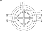
- FIG. 6 is a plan view of the vibration device according to the second embodiment.
- the present embodiment is different from the first embodiment in the arrangement of the hydrophilic film 25 and the water-repellent film 26. Except for the above points, the vibration device of the present embodiment has the same configuration as the vibration device 1 of the first embodiment.
- the (1, 2) mode is used.
- a plurality of antinodes of vibration are located on the light transmitting member 4.
- a node of vibration is located at a boundary of a plurality of antinodes of vibration.
- the hydrophilic film 25 is located at the boundary between the antinodes of the plurality of vibrations and at the nodes of the vibrations in the peripheral region B and the central region A of the light transmitting body 4.
- a plurality of water-repellent films 26 are provided, each of which is disposed at a portion where a plurality of vibration antinodes are located. This makes it possible to more easily move and atomize water droplets and the like attached to portions other than the portion where the node of vibration is located. Therefore, the field of view of the imaging element 10A can be more reliably secured.
- the (1, 2) mode is used.
- the hydrophilic film 25 is disposed at a position where a node of vibration is located in the vibration mode to be used, and a repellent is located at a position where an antinode of vibration is located.
- an aqueous membrane 26 is provided. Thereby, the field of view of the imaging element 10A can be more reliably secured.
- FIG. 7 is a schematic front sectional view of the vibration device according to the third embodiment.
- the present embodiment is different from the first embodiment in the configuration of the vibrating body 33. Except for the above points, the vibration device of the present embodiment has the same configuration as the vibration device 1 of the first embodiment.
- the vibrating body 33 includes a first vibrating body part 34 located on the first opening end 33a side, a second vibrating body part 35 located on the second opening end 33b side, and a first vibrating body. And a connecting portion 36 that connects the portion 34 and the second vibrating body portion 35.
- the first vibrating part 34 and the connecting part 36 are annular, and the second vibrating part 35 is cylindrical.
- the vibrating body 33 includes an annular first vibrating body portion 34, an annular connecting portion 36, and a cylindrical second vibrating body portion 35 such that their respective central axes are located on concentric axes. It is a tubular shape arranged.
- the outer peripheral edge and the inner peripheral edge refer to the outer peripheral edge and the inner peripheral edge in plan view.
- the first vibrating body portion 34 has a flange portion 39 that protrudes outside the second vibrating body portion 35.
- the outer peripheral edge of the flange portion 39 is located outside the outer peripheral edge of the second vibrating body portion 35.
- the vibrating body 33 has a flange portion 39 that protrudes outward from other portions of the vibrating body 33.
- the outer peripheral edge of the flange portion 39 is located outside the outer peripheral edge of another portion of the vibrating body 33.
- the first vibrator 34 has the flange 39. More specifically, the flange portion 39 of the first vibrator portion 34 is a portion that protrudes outward from the outer peripheral edge of the connecting portion 36 that is directly connected to the first vibrator portion 34.
- the outer peripheral edges of the connecting portion 36 and the second vibrating body portion 35 overlap each other, and the inner peripheral edge of the connecting portion 36 is closer than the inner peripheral edges of the second vibrating body portion 35 and the first vibrating body portion 34. It is located outside.
- the thickness of the connecting portion 36 is smaller than the thickness of the second vibrating body portion 35.
- the inner diameter of the connecting portion 36 is larger than the inner diameters of the other portions.
- a vibration mode in which antinodes of vibration are located on the outer peripheral edge of the flange portion 39 is used.
- the mode in which the vibration of the (m, n) mode is excited in the light transmitting body 4 is referred to as a first vibration mode
- the vibration mode in which the antinode of the vibration is located at the outer peripheral edge of the flange portion 39 is referred to as a second vibration mode. I do.
- FIG. 8 is a schematic cross-sectional view for explaining a second vibration mode in the third embodiment.
- FIG. 8 shows a portion corresponding to half of the cross section of the vibration device shown in FIG.
- the solid line indicates the original state of the vibrating device, and the dashed line indicates the vibrating state.
- the second vibration mode is a vibration mode in which the amplitude of the outer peripheral edge of the flange portion 39 is maximized. In the second vibration mode, the amplitude of the light transmitting body 4 is small.
- the control unit 12 of the present embodiment switches between the first vibration mode and the second vibration mode.
- Water droplets and the like located near the portion where the light transmitting body 4 and the vibrating body 3 are connected and near the outer peripheral edge of the light transmitting body 4 are easily moved to the outer peripheral edge of the flange portion 39 by the second vibration mode. Can be.
- water droplets and the like located near the outer peripheral edge of the light transmitting body 4 can be removed.
- the water droplets and the like moved to the outer peripheral edge of the flange portion 39 can be more reliably removed.
- water droplets and the like located outside the outer peripheral edge of the light transmitting body 4 can be reduced in optical disturbance or moved and atomized by the first vibration mode as in the first embodiment.
- the hydrophilic film 5 is disposed on the entire peripheral region B of the light transmitting member 4, and the hydrophilic film 5 is provided outside the light transmitting member 4. It has reached near the periphery. Therefore, water droplets and the like that are flattened at the portion where the hydrophilic film 5 is disposed can be quickly moved to the flange portion 39 by the second vibration mode and removed from the light transmitting member 4. Therefore, the field of view of the imaging element 10A can be more reliably secured.
- the first vibrator portion 34 has the flange portion 39.
- the second vibrating member 35 or the connecting portion 36 may have the flange 39. It is sufficient that the flange portion 39 is disposed closer to the light transmitting body 4 than the central position in the axial direction of the vibrating body 33.
- the light transmitting body 4 is connected to the outermost part of the vibrating body 33 in the axial direction.
- the position of the portion where the first vibrator 34 of the vibrator 33 is connected to the light transmitting body 4 is the same as the position of the flange 39.
- the distance between the connected portion and the flange portion 39 can be reduced as compared with the case where the position of the connected portion and the position of the flange portion 39 are different. . Therefore, in the second vibration mode, water droplets and the like can be suitably moved from the connected portion and the vicinity of the outer peripheral edge of the light transmitting member 4 to the flange portion 39.
- the light transmitting member 4 is not limited to the above, and may be connected to a portion other than the outermost portion in the axial direction of the vibrating member 33.
- a step is provided on the surface of the first vibrating body portion 34 on the light transmitting body 4 side, and the light transmitting body 4 is connected to a portion where the thickness of the first vibrating body portion 34 in the axial direction is thin. It may be.
- the connecting portion 36 is arranged such that the outer peripheral edges of the connecting portion 36 and the second vibrator portion 35 overlap in plan view, but the arrangement of the connecting portion 36 is not limited to this.
- the outer peripheral edges of the connecting portion 36 and the light transmitting body 4 may overlap.
- the flange portion 39 can be elongated without reducing the thickness of the first vibrating body portion 34 and the connecting portion 36 and without increasing the outer diameter of the first vibrating body portion 34. Therefore, the amplitude of the flange portion 39 in the second vibration mode can be increased without lowering the strength and increasing the size.
Abstract
Provided is a vibration device in which the detection region of an optical detection element can be more reliably ensured. This vibration device 1 is provided with a translucent body 4 which is disposed so as to include at least part the detection range of an image capturing element 10A (optical detection element), and a vibration element 2 which has a vibrator 3 connected to the translucent body 4. The translucent body 4 has a center region A and a peripheral region B which is located around the center region A. A hydrophilic film 5 is provided in the peripheral region B of the translucent body 4.
Description
本発明は、機械的振動によって水滴等を除去することが可能な振動装置及び光学検出装置に関する。
The present invention relates to a vibration device and an optical detection device capable of removing water droplets and the like by mechanical vibration.
従来、監視装置として用いられるカメラ等のイメージングデバイスにおいては、その視野を常に明瞭にすることが求められている。特に、車載用途等の屋外で使用されるカメラにおいては、雨滴等の水滴を除去するための機構が種々提案されている。下記の特許文献1には、カメラ本体の前方に配置される、透光性部分を有する振動装置が開示されている。この振動装置においては、透光性部分を大きく振動させることにより、透光体部に付着した水滴を霧化させる。特許文献1には、撮影される領域以外に親水性部分を構成することにより、水滴を親水性部分側に移動させ得ることが記載されている。
Conventionally, imaging devices such as cameras used as surveillance devices have been required to always have a clear visual field. In particular, for a camera used outdoors such as in a vehicle, various mechanisms for removing water droplets such as raindrops have been proposed. Patent Literature 1 below discloses a vibration device having a light-transmitting portion disposed in front of a camera body. In this vibrating device, water droplets adhering to the light transmitting portion are atomized by vibrating the light transmitting portion largely. Patent Literature 1 describes that a water droplet can be moved to a hydrophilic portion side by forming a hydrophilic portion other than a region to be photographed.
特許文献1に記載された振動装置では、透光性部分における、カメラ本体の視野領域に位置する部分に、振動の腹及び振動の節が形成される。このとき、透光性部分に水滴が付着すると、振動の腹に向かい水滴が移動し、振動の腹付近において水滴が霧化される。しかしながら、振動の節に位置する水滴は、振動の腹の方に移動し難い。そのため、水滴が残留し、カメラ本体の視野が阻害されるおそれがあった。
振動 In the vibration device described in Patent Literature 1, antinodes of vibration and nodes of vibration are formed in a portion of the translucent portion located in the visual field region of the camera body. At this time, if a water droplet adheres to the translucent portion, the water droplet moves toward the antinode of the vibration, and the water droplet is atomized near the antinode of the vibration. However, the water droplet located at the node of the vibration is hard to move toward the antinode of the vibration. For this reason, water droplets may remain and the field of view of the camera body may be obstructed.
本発明の目的は、光学検出素子の検出領域をより確実に確保することができる、振動装置及び光学検出装置を提供することにある。
An object of the present invention is to provide a vibration device and an optical detection device that can more reliably secure a detection area of an optical detection element.
本発明に係る振動装置は、光学検出素子の検出領域の少なくとも一部を含むように配置される透光体と、前記透光体に連結されている振動体を有する振動素子とを備え、前記透光体が中央領域と、前記中央領域の周辺に位置する周辺領域とを有し、前記透光体の前記周辺領域に親水性膜が設けられている。
The vibration device according to the present invention includes a light-transmitting member disposed so as to include at least a part of the detection region of the optical detection element, and a vibration element having a vibration member connected to the light-transmitting member, The light-transmitting member has a central region and a peripheral region located around the central region, and a hydrophilic film is provided on the peripheral region of the light-transmitting member.
本発明に係る光学検出装置は、本発明に従って構成された振動装置と、前記透光体に検出領域が含まれるように配置されている光学検出素子とを備える。
The optical detection device according to the present invention includes a vibration device configured according to the present invention, and an optical detection element arranged so that the light transmitting body includes a detection region.
本発明によれば、光学検出素子の検出領域をより確実に確保することができる、振動装置及び光学検出装置を提供することができる。
According to the present invention, it is possible to provide a vibration device and an optical detection device that can more reliably secure a detection area of an optical detection element.
以下、図面を参照しつつ、本発明の具体的な実施形態を説明することにより、本発明を明らかにする。
Hereinafter, the present invention will be clarified by describing specific embodiments of the present invention with reference to the drawings.
なお、本明細書に記載の各実施形態は、例示的なものであり、異なる実施形態間において、構成の部分的な置換または組み合わせが可能であることを指摘しておく。
Note that each embodiment described in the present specification is merely an example, and it should be pointed out that partial replacement or combination of configurations between different embodiments is possible.
図1は、第1の実施形態に係る振動装置を有するイメージングデバイスの模式的斜視図である。図2は、第1の実施形態に係る振動装置を有するイメージングデバイスの模式的正面断面図である。なお、図2以外の断面図においては、後述する制御部を省略することがある。
FIG. 1 is a schematic perspective view of an imaging device having the vibration device according to the first embodiment. FIG. 2 is a schematic front sectional view of an imaging device having the vibration device according to the first embodiment. In the cross-sectional views other than FIG. 2, a control unit described later may be omitted.
図1に示すイメージングデバイス10は振動装置1を有する。振動装置1は、振動により水滴や異物を移動させ、または水滴等を霧化することにより、撮像素子の視野内から水滴や異物を除去する振動装置である。図2に示すように、振動装置1は、筒状の振動体3を含む振動素子2と、振動素子2の開口部を覆うように設けられている透光体4と、振動素子2に電気的に接続されている制御部12とを有する。
イ メ ー ジ ン グ The imaging device 10 shown in FIG. The vibrating device 1 is a vibrating device that removes water droplets and foreign matter from the field of view of the image sensor by moving water droplets and foreign matter by vibration, or atomizing the water droplets and the like. As shown in FIG. 2, the vibration device 1 includes a vibration element 2 including a cylindrical vibration body 3, a light transmitting body 4 provided to cover an opening of the vibration element 2, and an electric And a control unit 12 that is electrically connected.
イメージングデバイス10は、振動装置1を一端側で支持している筒状のケース部材13と、ケース部材13の他端に固定されているベース部材14とを有する。振動装置1、ケース部材13及びベース部材14により囲まれた内部空間内に、撮像素子10Aが配置されている。それによって、本発明の一実施形態に係る光学検出装置としてのイメージングデバイス10が構成されている。
The imaging device 10 has a cylindrical case member 13 that supports the vibration device 1 at one end, and a base member 14 that is fixed to the other end of the case member 13. An image sensor 10A is arranged in an internal space surrounded by the vibration device 1, the case member 13, and the base member 14. Thereby, an imaging device 10 as an optical detection device according to one embodiment of the present invention is configured.
撮像素子10Aとしては、例えば、可視領域から遠赤外領域のいずれかの波長の光を受光する、CMOS、CCD、ボロメーターやサーモパイル等を挙げることができる。イメージングデバイス10としては、例えば、カメラ、RadarやLIDARデバイス等を挙げることができる。
As the imaging element 10A, for example, a CMOS, a CCD, a bolometer, a thermopile, or the like that receives light of any wavelength from the visible region to the far infrared region can be used. Examples of the imaging device 10 include a camera, a Radar and a LIDAR device, and the like.
図2に示すように、ケース部材13はベース部材14上に固定されている。ベース部材14上に複数の脚部15が固定されている。複数の脚部15上に基板16が固定されている。基板16上に撮像素子10Aが固定されている。撮像素子10Aは、撮像素子本体10a及びレンズモジュール10bを有する。撮像素子10Aにおけるレンズモジュール10b側の部分が、振動装置1の内部空間内に位置しており、残りの部分がケース部材13の内部空間内に位置している。なお、撮像素子10A全体が振動装置1の内部空間内に位置していてもよい。
ケ ー ス As shown in FIG. 2, the case member 13 is fixed on the base member 14. A plurality of legs 15 are fixed on the base member 14. A board 16 is fixed on the plurality of legs 15. The image sensor 10A is fixed on the substrate 16. The imaging device 10A has an imaging device body 10a and a lens module 10b. The portion on the lens module 10b side of the imaging element 10A is located in the internal space of the vibration device 1, and the remaining portion is located in the internal space of the case member 13. Note that the entire imaging element 10A may be located in the internal space of the vibration device 1.
本実施形態では、基板16の少なくとも一方の主面またはベース部材14の一方の主面に撮像素子10Aを駆動する回路や上記制御部12が設けられている。
In the present embodiment, a circuit for driving the image sensor 10A and the control unit 12 are provided on at least one main surface of the substrate 16 or one main surface of the base member 14.
なお、振動装置1、ケース部材13及びベース部材14により囲まれた内部空間内には、撮像素子10A以外の、エネルギー線を光学的に検出する光学検出素子が配置されていてもよい。検出するエネルギー線としては、例えば、電磁波や赤外線等の活性エネルギー線であってもよい。図2に示すイメージングデバイス10においては、撮像素子10Aの検出領域としての視野が、透光体4に含まれる。本実施形態では、この視野の中心は、透光体4の中央領域A内に位置しており、視野の周辺領域が、透光体4の周辺領域Bに位置している。もっとも、これに限定されず、透光体4は、撮像素子10Aの視野の少なくとも一部を含むように配置されていればよい。ここで、本明細書における透光性とは、少なくとも上記光学検出素子が検出する波長のエネルギー線や光が透過する透光性をいう。
In the internal space surrounded by the vibration device 1, the case member 13, and the base member 14, an optical detection element other than the imaging element 10A for optically detecting an energy ray may be arranged. The energy ray to be detected may be, for example, an active energy ray such as an electromagnetic wave or an infrared ray. In the imaging device 10 shown in FIG. 2, a field of view as a detection region of the imaging element 10 </ b> A is included in the light transmitting body 4. In the present embodiment, the center of the visual field is located in the central area A of the light transmitting body 4, and the peripheral area of the visual field is located in the peripheral area B of the light transmitting body 4. However, the present invention is not limited to this, and the light transmitting body 4 may be disposed so as to include at least a part of the field of view of the imaging element 10A. Here, the term "light-transmitting property" in the present specification refers to a light-transmitting property at which an energy ray or light having a wavelength detected by the optical detection element is transmitted.
図1及び図2に示すイメージングデバイス10は一例であって、イメージングデバイス10の構成は上記に限定されない。イメージングデバイス10は、振動装置1及び撮像素子10Aを有していればよい。
The imaging device 10 shown in FIGS. 1 and 2 is an example, and the configuration of the imaging device 10 is not limited to the above. The imaging device 10 only needs to include the vibration device 1 and the imaging element 10A.
以下において、振動装置1の詳細を説明する。
詳細 The details of the vibration device 1 will be described below.
図2に示すように、振動素子2は振動体3及び圧電振動子7を有する。本実施形態では、振動体3は略円筒状であり、第1の開口端部3a及び第2の開口端部3bを有する。ここで、第1の開口端部3a及び第2の開口端部3bを結ぶ方向を軸方向とし、軸方向に直交する方向を径方向とする。振動体3は、第1の開口端部3a側に位置し、かつ径方向内側に延びる延長部3cを有する。上記透光体4は、振動体3の開口部を覆うように、第1の開口端部3aにおける延長部3cに位置する部分に連結されている。
振動 As shown in FIG. 2, the vibration element 2 has a vibration body 3 and a piezoelectric vibrator 7. In the present embodiment, the vibrating body 3 is substantially cylindrical and has a first open end 3a and a second open end 3b. Here, the direction connecting the first open end 3a and the second open end 3b is defined as the axial direction, and the direction orthogonal to the axial direction is defined as the radial direction. The vibrating body 3 has an extension 3c located on the first opening end 3a side and extending radially inward. The light transmitting member 4 is connected to a portion of the first opening end 3a located at the extension 3c so as to cover the opening of the vibrating member 3.
振動体3は、第1の開口端部3aと第2の開口端部3bとの間に位置しているヒンジ部3dを有する。ヒンジ部3dは径方向外側に延びている。振動装置1は、ヒンジ部3dにおいて、ケース部材13に支持されている。ここで、振動体3の径方向における厚みを肉厚としたときに、ヒンジ部3dと延長部3cとの間に位置している部分の肉厚は、ヒンジ部3dと第2の開口端部3bとの間に位置している部分の肉厚より薄い。
The vibrating body 3 has a hinge 3d located between the first open end 3a and the second open end 3b. The hinge 3d extends radially outward. The vibration device 1 is supported by the case member 13 at the hinge 3d. Here, when the thickness in the radial direction of the vibrating body 3 is a thickness, the thickness of the portion located between the hinge 3d and the extension 3c is the thickness of the hinge 3d and the second opening end. 3b.
なお、振動体3はヒンジ部3d及び延長部3cを有していなくともよく、振動体3の肉厚は全ての部分において同じであってもよい。振動体3は筒状であればよく、例えば、振動体3は円筒状や角筒状であってもよい。
Note that the vibrating body 3 may not have the hinge portion 3d and the extension portion 3c, and the thickness of the vibrating body 3 may be the same in all portions. The vibrating body 3 may have a cylindrical shape. For example, the vibrating body 3 may have a cylindrical shape or a rectangular cylindrical shape.
振動素子2においては、振動体3の第2の開口端部3bに、圧電振動子7が配置されている。圧電振動子7は、透光体4及び振動体3の連結体を振動させる。
圧 電 In the vibrating element 2, the piezoelectric vibrator 7 is disposed at the second opening end 3 b of the vibrating body 3. The piezoelectric vibrator 7 vibrates the connected body of the light transmitting body 4 and the vibrating body 3.
図3は、第1の実施形態における圧電振動子の模式的斜視図である。
FIG. 3 is a schematic perspective view of the piezoelectric vibrator according to the first embodiment.
圧電振動子7は円環状の圧電体8を有する。圧電体8は、例えば、Pb(Zr,Ti)O3や(K,Na)NbO3等の適宜の圧電セラミックスまたはLiTaO3やLiNbO3等の適宜の圧電単結晶からなる。圧電体8の一方主面には電極9aが設けられており、他方主面には電極9bが設けられている。
The piezoelectric vibrator 7 has an annular piezoelectric body 8. The piezoelectric body 8 is made of, for example, an appropriate piezoelectric ceramic such as Pb (Zr, Ti) O 3 or (K, Na) NbO 3 or an appropriate piezoelectric single crystal such as LiTaO 3 or LiNbO 3 . An electrode 9a is provided on one main surface of the piezoelectric body 8, and an electrode 9b is provided on the other main surface.
本実施形態では、振動体3に1つの円環状の圧電振動子7が配置されている。なお、圧電振動子7の形状及び個数は上記に限定されない。例えば、平面視において、振動体3の中心を回転軸とした周回方向に沿い、複数の圧電振動子が配置されていてもよい。
In this embodiment, one annular piezoelectric vibrator 7 is disposed on the vibrating body 3. The shape and the number of the piezoelectric vibrators 7 are not limited to the above. For example, in a plan view, a plurality of piezoelectric vibrators may be arranged along a circumferential direction with the center of the vibrating body 3 as a rotation axis.
透光体4は、本実施形態ではドーム状である。なお、透光体4の形状は上記に限られず、例えば、円板状等であってもよい。透光体4は透光性材料からなる。透光性材料としては、例えば、透光性のプラスチック、ガラスまたは透光性のセラミックス等を用いることができる。
光 The translucent member 4 has a dome shape in the present embodiment. The shape of the light transmitting body 4 is not limited to the above, and may be, for example, a disk shape. The light transmitting body 4 is made of a light transmitting material. As the translucent material, for example, translucent plastic, glass, or translucent ceramics can be used.
透光体4は、中央領域Aと、中央領域Aの周辺に位置する周辺領域Bとを有する。透光体4の中央領域Aには撥水性膜6が設けられている。他方、透光体4の周辺領域Bには親水性膜5が設けられている。より具体的には、親水性膜5及び撥水性膜6は、透光体4における、振動装置1の内部に光やエネルギー線を透過させる外表面に設けられている。撥水性膜6の材料としては、例えば、ポリテトラフルオロエチレンのようなフッ素系材料やパーフルオロアルキル基含有シランなどのシリコン系材料等を挙げることができる。親水性膜5の材料としては、例えば、TiO2などの無機系材料や親水化PVDFのような有機系材料等を挙げることができる。なお、透光体4には、撥水性膜6は必ずしも設けられていなくともよい。
The light transmitting body 4 has a central area A and a peripheral area B located around the central area A. A water-repellent film 6 is provided in the central region A of the light transmitting body 4. On the other hand, a hydrophilic film 5 is provided in the peripheral region B of the light transmitting body 4. More specifically, the hydrophilic film 5 and the water-repellent film 6 are provided on the outer surface of the light transmitting body 4 that transmits light and energy rays into the inside of the vibration device 1. Examples of the material of the water-repellent film 6 include a fluorine-based material such as polytetrafluoroethylene and a silicon-based material such as a perfluoroalkyl group-containing silane. Examples of the material of the hydrophilic film 5 include an inorganic material such as TiO 2 and an organic material such as hydrophilic PVDF. Note that the water-repellent film 6 does not necessarily have to be provided on the translucent member 4.
振動素子2に上記制御部12が電気的に接続されている。より具体的には、制御部12は圧電振動子7に電気的に接続されている。制御部12は、圧電振動子7による、透光体4及び振動体3の連結体の振動を制御する。制御部12により、複数の振動モードを切り替えてもよい。本実施形態では、制御部12は、振動体3のヒンジ部3dに振動の節が位置するように、透光体4及び振動体3の連結体を振動させる。それによって、ケース部材13により振動装置1を容易に支持することができ、イメージングデバイス10の密閉性を高めることができる。加えて、ケース部材13による支持によって、振動装置1の振動を阻害し難い。
制 御 The control unit 12 is electrically connected to the vibration element 2. More specifically, the control unit 12 is electrically connected to the piezoelectric vibrator 7. The control unit 12 controls the vibration of the connected body of the light transmitting body 4 and the vibrating body 3 by the piezoelectric vibrator 7. A plurality of vibration modes may be switched by the control unit 12. In the present embodiment, the control unit 12 vibrates the connected body of the light transmitting body 4 and the vibrating body 3 so that the node of the vibration is located at the hinge 3d of the vibrating body 3. Thereby, the vibration device 1 can be easily supported by the case member 13, and the sealing property of the imaging device 10 can be improved. In addition, the support of the case member 13 makes it difficult to hinder the vibration of the vibration device 1.
本実施形態の特徴は、透光体4の周辺領域Bに親水性膜5が設けられていることにある。それによって、光学検出素子の検出領域としての、撮像素子10Aの視野をより確実に確保することができる。これを、振動装置1が利用する振動モードの詳細と共に、以下において説明する。
特 徴 The feature of this embodiment is that the hydrophilic film 5 is provided in the peripheral region B of the light transmitting body 4. Thereby, the visual field of the imaging element 10A as a detection area of the optical detection element can be more reliably secured. This will be described below together with the details of the vibration mode used by the vibration device 1.
図4は、各振動モードを説明するための模式図である。図4においては、平面視したときの透光体における各領域の振動の位相を示す。+の符号が付されている領域と、-の符号が付されている領域とは、振動の位相が互いに逆であることを示す。
FIG. 4 is a schematic diagram for explaining each vibration mode. FIG. 4 shows the phase of vibration of each region in the light transmitting body when viewed in plan. The region marked with a + sign and the region marked with a-sign indicate that the phases of vibration are opposite to each other.
振動モードは(m,n)モードで表すことができる。ここで、m及びnは整数である。mは周回方向に延びる振動の節のラインの本数であり、nは径方向に延びる振動の節のラインの本数である。本実施形態においては、(1,0)モード、(1,1)モードまたは(1,2)モードを利用する。なお、(1,0)モード、(1,1)モード及び(1,2)モードにおける周回方向に延びる振動の節のラインは、透光体4の周辺領域Bに位置する。
The vibration mode can be represented by the (m, n) mode. Here, m and n are integers. m is the number of vibration node lines extending in the circumferential direction, and n is the number of vibration node lines extending in the radial direction. In the present embodiment, the (1,0) mode, the (1,1) mode, or the (1,2) mode is used. The line of the node of the vibration extending in the circumferential direction in the (1,0) mode, the (1,1) mode, and the (1,2) mode is located in the peripheral region B of the light transmitting body 4.
ここで、振動装置1の圧電振動子7は、透光体4において(1,0)モード、(1,1)モードまたは(1,2)モードの振動を励振させることができるように構成されている。なお、圧電振動子7に印加する電圧等を上記制御部12により制御することによって、(1,0)モード、(1,1)モードまたは(1,2)モードの振動を励振させる。
Here, the piezoelectric vibrator 7 of the vibration device 1 is configured to be able to excite the (1,0) mode, the (1,1) mode, or the (1,2) mode vibration in the light transmitting body 4. ing. The control section 12 controls the voltage or the like applied to the piezoelectric vibrator 7 to excite the (1,0) mode, (1,1) mode, or (1,2) mode vibration.
図5(a)~図5(c)は、第1の実施形態における圧電体の分極構造の例を説明するための模式的斜視図である。図5(a)において、+の符号が付されている領域は、分極方向が圧電体の図5(a)における下面から上面に向かう方向となっている領域であることを示す。-の符号が付されている領域は、分極方向が圧電体の上面から下面に向かう方向となっている領域であることを示す。図5(b)及び図5(c)においても同様である。
FIGS. 5A to 5C are schematic perspective views illustrating examples of the polarization structure of the piezoelectric body according to the first embodiment. In FIG. 5A, a region with a + sign indicates a region in which the polarization direction is from the lower surface to the upper surface in FIG. 5A of the piezoelectric body. A region with a minus sign indicates that the polarization direction is a direction from the upper surface to the lower surface of the piezoelectric body. The same applies to FIGS. 5B and 5C.
図5(a)では、周回方向に配置された領域の分極方向が全て同じである。ここで、図3に示す圧電振動子7の電極9a及び電極9bは円環状である。よって、図5(a)に示す分極構造の圧電体8を用いる場合、透光体4において(1,0)モードの振動が励振される。図5(b)では、周回方向に4分割された領域において、中心を介して対向している両側の領域の分極方向が反対となっている。図5(b)に示す分極構造の圧電体8を用いる場合、透光体4において(1,1)モードの振動が励振される。図5(c)では、周回方向に4分割された領域において、中心を介して対向している両側の領域の分極方向が等しくされている。図5(c)に示す分極構造の圧電体8を用いる場合、透光体4において(1,2)モードの振動が励振される。
で は In FIG. 5A, the polarization directions of the regions arranged in the circumferential direction are all the same. Here, the electrodes 9a and 9b of the piezoelectric vibrator 7 shown in FIG. 3 are annular. Therefore, when the piezoelectric body 8 having the polarization structure shown in FIG. 5A is used, the (1, 0) mode vibration is excited in the light transmitting body 4. In FIG. 5B, in the region divided into four in the circumferential direction, the polarization directions of the regions on both sides facing each other via the center are opposite. When the piezoelectric body 8 having the polarization structure shown in FIG. 5B is used, the (1,1) mode vibration is excited in the light transmitting body 4. In FIG. 5C, in the region divided into four in the circumferential direction, the polarization directions of the regions on both sides facing each other via the center are equalized. When the piezoelectric body 8 having the polarization structure shown in FIG. 5C is used, (1,2) mode vibration is excited in the light transmitting body 4.
ここで、図3に示した電極9a及び電極9bは周回方向において分割されていてもよく、分割された各電極が圧電体8の上記各領域に配置されていてもよい。この場合には、図5(a)に示す分極構造の圧電体8を用いる場合においても、中心を介して対向している両側の領域に互いに逆の位相の交流電圧を印加することにより、透光体4において(1,1)モードの振動を励振させることができる。あるいは、中心を介して対向している両側の領域に同じ位相の交流電圧を印加することにより、透光体4において(1,2)モードの振動を励振させることができる。なお、制御部12により、各振動モードを切り替えてもよい。
Here, the electrode 9a and the electrode 9b shown in FIG. 3 may be divided in the circumferential direction, and the divided electrodes may be arranged in the above-described regions of the piezoelectric body 8. In this case, even when the piezoelectric body 8 having the polarization structure shown in FIG. 5A is used, the AC voltages having phases opposite to each other are applied to the regions on both sides facing each other with the center therebetween. The (1,1) mode vibration can be excited in the optical body 4. Alternatively, it is possible to excite the (1,2) mode vibration in the light transmitting member 4 by applying an AC voltage having the same phase to the regions on both sides opposed to each other with the center interposed therebetween. In addition, each vibration mode may be switched by the control unit 12.
(1,0)モード、(1,1)モード及び(1,2)モードにおける振動の腹は、図2に示す透光体4の中央領域Aに位置している。透光体4における振動の腹付近に付着した水滴等は霧化され、除去される。さらに、水滴等は振動の腹に向かい移動する。そのため、振動の腹付近に位置していなかった水滴等を、振動の腹に向かい移動させ、霧化させることにより除去できる。
The antinode of the vibration in the (1,0) mode, (1,1) mode and (1,2) mode is located in the central area A of the light transmitting body 4 shown in FIG. Water droplets and the like attached near the antinode of the vibration in the light transmitting body 4 are atomized and removed. Further, water droplets and the like move toward the antinode of vibration. Therefore, water droplets and the like that are not located near the antinode of vibration can be removed by moving toward the antinode of vibration and atomizing.
他方、(1,0)モード、(1,1)モード及び(1,2)モードにおける振動の節が透光体4の周辺領域Bに位置している。振動の節近傍における水滴等は霧化させることができず、かつ移動させ難い。そのため、上述したように、従来の構成においては水滴が残留し、撮像素子の視野を十分に確保できないおそれがある。
On the other hand, the nodes of the vibration in the (1,0) mode, the (1,1) mode, and the (1,2) mode are located in the peripheral region B of the light transmitting body 4. Water droplets and the like near the nodes of vibration cannot be atomized and are difficult to move. Therefore, as described above, water droplets remain in the conventional configuration, and there is a possibility that the visual field of the image sensor cannot be sufficiently secured.
これに対して、図2に示す本実施形態では、透光体4の周辺領域Bに親水性膜5が設けられている。より具体的には、親水性膜5は、周辺領域Bにおいて、振動の節が位置する部分を覆うように設けられている。なお、本明細書において、振動の節に位置する部分とは、振動の節近傍に位置する部分を含む。それによって、振動の節に位置する水滴等を平坦化させ、水滴等が付着したことによる光学的障害を低減させることができる。他方、透光体4において、中央領域Aに位置する水滴等は、容易に移動及び霧化させることができる。従って、撮像素子10Aの視野をより確実に確保することができる。
In contrast, in the present embodiment shown in FIG. 2, the hydrophilic film 5 is provided in the peripheral region B of the light transmitting body 4. More specifically, the hydrophilic film 5 is provided so as to cover a portion where the node of vibration is located in the peripheral region B. In this specification, a portion located at a node of vibration includes a portion located near a node of vibration. This makes it possible to flatten water droplets and the like located at nodes of the vibration, and reduce optical obstacles caused by the attachment of the water droplets and the like. On the other hand, in the light transmitting body 4, water droplets and the like located in the central region A can be easily moved and atomized. Therefore, the visual field of the image sensor 10A can be more reliably secured.
本実施形態のように、中央領域Aには撥水性膜6が設けられていることが好ましい。それによって、水滴等をより一層容易に移動及び霧化させることができる。なお、振動装置1においては、透光体4の中央領域Aの全体に撥水性膜6が設けられている。この場合には、中央領域Aに振動の節が位置しない(1,0)モードを利用することが好ましい。それによって、より確実に、かつより一層容易に水滴等を移動及び霧化することができる。なお、制御部12により、他の振動モードと(1,0)モードとを切り替えてもよい。
、 As in the present embodiment, it is preferable that the water repellent film 6 is provided in the central region A. Thereby, water droplets and the like can be more easily moved and atomized. In the vibration device 1, the water-repellent film 6 is provided on the entire central region A of the light transmitting body 4. In this case, it is preferable to use the (1, 0) mode in which no node of vibration is located in the central region A. This makes it possible to move and atomize water droplets and the like more reliably and more easily. The control unit 12 may switch between another vibration mode and the (1, 0) mode.
他方、撥水性膜6は中央領域Aの一部に設けられていてもよい。この場合には、撥水性膜6は、透光体4の振動の腹が位置する部分に設けられていることが好ましい。それによって、水滴等を容易に霧化させることができる。
On the other hand, the water repellent film 6 may be provided in a part of the central region A. In this case, it is preferable that the water-repellent film 6 is provided in a portion where the antinode of vibration of the light transmitting body 4 is located. Thereby, water droplets and the like can be easily atomized.
親水性膜5は、周辺領域Bの全体に設けられている。なお、親水性膜5は、利用する振動モードの振動の節が位置する部分のみに設けられていてもよい。この場合においても、振動の節に位置する水滴等を平坦化させることができ、撮像素子10Aの視野をより確実に確保することができる。
The hydrophilic film 5 is provided on the entire peripheral region B. In addition, the hydrophilic film 5 may be provided only in a portion where a node of the vibration of the vibration mode to be used is located. Also in this case, water droplets and the like located at the nodes of the vibration can be flattened, and the field of view of the image sensor 10A can be more reliably secured.
本実施形態では、透光体4における撮像素子10Aの視野を含む領域に振動の節が位置している。親水性膜5は、透光体4の周辺領域Bにおける、撮像素子10Aの視野を含む領域に設けられている。それによって、水滴等による、撮像素子10Aの視野における光学的障害を低減することができる。なお、周辺領域Bにおいて、撮像素子10Aの視野を含まない領域に振動の節が位置する場合にも、振動の節が位置する部分に残留して増加した水滴等が撮像素子10Aの視野に侵入し、視野を確保することができないおそれがある。親水性膜5は、周辺領域Bにおける、撮像素子10Aの視野を含まない領域に設けられていてもよい。それによって、光学的障害を生じさせる水滴等の上記視野への侵入を抑制することができる。従って、この場合においても、撮像素子10Aの視野をより確実に確保することができる。
In the present embodiment, the nodes of the vibration are located in a region including the visual field of the imaging element 10A in the light transmitting body 4. The hydrophilic film 5 is provided in a region including the visual field of the imaging element 10A in the peripheral region B of the light transmitting body 4. This can reduce optical obstacles in the field of view of the image sensor 10A due to water drops or the like. In the peripheral area B, even when the nodes of vibration are located in a region not including the field of view of the imaging element 10A, water droplets and the like remaining and increasing at the portion where the nodes of vibration are located enter the field of view of the imaging element 10A. However, there is a possibility that the visual field cannot be secured. The hydrophilic film 5 may be provided in a region of the peripheral region B that does not include the field of view of the imaging element 10A. Thus, it is possible to prevent water droplets or the like that cause an optical obstacle from entering the visual field. Therefore, also in this case, the field of view of the image sensor 10A can be more reliably secured.
図6は、第2の実施形態に係る振動装置の平面図である。
FIG. 6 is a plan view of the vibration device according to the second embodiment.
本実施形態は、親水性膜25及び撥水性膜26の配置が第1の実施形態と異なる。上記の点以外においては、本実施形態の振動装置は第1の実施形態の振動装置1と同様の構成を有する。
The present embodiment is different from the first embodiment in the arrangement of the hydrophilic film 25 and the water-repellent film 26. Except for the above points, the vibration device of the present embodiment has the same configuration as the vibration device 1 of the first embodiment.
本実施形態では(1,2)モードを利用する。(1,2)モードにおいては、透光体4に複数の振動の腹が位置する。複数の振動の腹の境界に振動の節が位置する。親水性膜25は、透光体4の周辺領域B及び中央領域Aにおいて、複数の振動の腹の境界に位置し、振動の節に位置する部分に設けられている。それによって、透光体4の周辺領域Bに加えて、中央領域Aにおいて振動の節に位置する部分に付着した水滴等を平坦化し、光学的障害を低減させることができる。
で は In the present embodiment, the (1, 2) mode is used. In the (1, 2) mode, a plurality of antinodes of vibration are located on the light transmitting member 4. A node of vibration is located at a boundary of a plurality of antinodes of vibration. The hydrophilic film 25 is located at the boundary between the antinodes of the plurality of vibrations and at the nodes of the vibrations in the peripheral region B and the central region A of the light transmitting body 4. Thereby, in addition to the peripheral region B of the light transmitting member 4, water droplets and the like attached to the portion located at the node of the vibration in the central region A can be flattened, and the optical obstacle can be reduced.
撥水性膜26は複数設けられており、複数の振動の腹が位置する部分にそれぞれ配置されている。それによって、振動の節が位置する部分以外に付着した水滴等をより一層容易に移動及び霧化させることができる。従って、撮像素子10Aの視野をより一層確実に確保することができる。
A plurality of water-repellent films 26 are provided, each of which is disposed at a portion where a plurality of vibration antinodes are located. This makes it possible to more easily move and atomize water droplets and the like attached to portions other than the portion where the node of vibration is located. Therefore, the field of view of the imaging element 10A can be more reliably secured.
本実施形態では(1,2)モードを利用する例を示す。なお、(1,1)モードや他の振動モードを利用する場合には、利用する振動モードにおいて振動の節が位置する部分に親水性膜25を配置し、振動の腹が位置する部分に撥水性膜26を配置することが好ましい。それによって、撮像素子10Aの視野をより一層確実に確保することができる。
In this embodiment, an example in which the (1, 2) mode is used will be described. When the (1, 1) mode or another vibration mode is used, the hydrophilic film 25 is disposed at a position where a node of vibration is located in the vibration mode to be used, and a repellent is located at a position where an antinode of vibration is located. Preferably, an aqueous membrane 26 is provided. Thereby, the field of view of the imaging element 10A can be more reliably secured.
図7は、第3の実施形態に係る振動装置の模式的正面断面図である。
FIG. 7 is a schematic front sectional view of the vibration device according to the third embodiment.
本実施形態は、振動体33の構成が第1の実施形態と異なる。上記の点以外においては、本実施形態の振動装置は第1の実施形態の振動装置1と同様の構成を有する。
The present embodiment is different from the first embodiment in the configuration of the vibrating body 33. Except for the above points, the vibration device of the present embodiment has the same configuration as the vibration device 1 of the first embodiment.
振動体33は、第1の開口端部33a側に位置する第1の振動体部34と、第2の開口端部33b側に位置する第2の振動体部35と、第1の振動体部34及び第2の振動体部35を連結している連結部36とを有する。第1の振動体部34及び連結部36は円環状であり、第2の振動体部35は円筒状である。振動体33は、円環状の第1の振動体部34と、円環状の連結部36と、円筒状の第2の振動体部35とをそれぞれの中心軸が同心軸上に位置するように配置された筒状である。
The vibrating body 33 includes a first vibrating body part 34 located on the first opening end 33a side, a second vibrating body part 35 located on the second opening end 33b side, and a first vibrating body. And a connecting portion 36 that connects the portion 34 and the second vibrating body portion 35. The first vibrating part 34 and the connecting part 36 are annular, and the second vibrating part 35 is cylindrical. The vibrating body 33 includes an annular first vibrating body portion 34, an annular connecting portion 36, and a cylindrical second vibrating body portion 35 such that their respective central axes are located on concentric axes. It is a tubular shape arranged.
ここで、本明細書において、特に断りのない場合には、外周縁及び内周縁は平面視における外周縁及び内周縁をいう。平面視において、第1の振動体部34は、第2の振動体部35よりも外側に張り出したフランジ部39を有する。フランジ部39の外周縁は、第2の振動体部35の外周縁よりも外側に位置している。平面視において、振動体33は、振動体33の他の部分よりも外側に張り出したフランジ部39を有する。フランジ部39の外周縁は、振動体33の他の部分の外周縁よりも外側に位置している。本実施形態では、第1の振動体部34がフランジ部39を有する。より具体的には、第1の振動体部34におけるフランジ部39は、第1の振動体部34に直接連結されている連結部36の外周縁から外側に張り出した部分である。
Here, in this specification, unless otherwise specified, the outer peripheral edge and the inner peripheral edge refer to the outer peripheral edge and the inner peripheral edge in plan view. In plan view, the first vibrating body portion 34 has a flange portion 39 that protrudes outside the second vibrating body portion 35. The outer peripheral edge of the flange portion 39 is located outside the outer peripheral edge of the second vibrating body portion 35. In a plan view, the vibrating body 33 has a flange portion 39 that protrudes outward from other portions of the vibrating body 33. The outer peripheral edge of the flange portion 39 is located outside the outer peripheral edge of another portion of the vibrating body 33. In the present embodiment, the first vibrator 34 has the flange 39. More specifically, the flange portion 39 of the first vibrator portion 34 is a portion that protrudes outward from the outer peripheral edge of the connecting portion 36 that is directly connected to the first vibrator portion 34.
平面視において、連結部36及び第2の振動体部35の外周縁は重なっており、かつ連結部36の内周縁が第2の振動体部35及び第1の振動体部34の内周縁より外側に位置している。振動体33の各部分における、径方向における外側の側面と内側の側面との距離を肉厚としたときに、連結部36の肉厚は第2の振動体部35の肉厚よりも薄い。振動体33においては、連結部36における内径が、他の部分の内径よりも大きい。
In a plan view, the outer peripheral edges of the connecting portion 36 and the second vibrating body portion 35 overlap each other, and the inner peripheral edge of the connecting portion 36 is closer than the inner peripheral edges of the second vibrating body portion 35 and the first vibrating body portion 34. It is located outside. When the distance between the outer side surface and the inner side surface in the radial direction in each portion of the vibrating body 33 is defined as the thickness, the thickness of the connecting portion 36 is smaller than the thickness of the second vibrating body portion 35. In the vibrating body 33, the inner diameter of the connecting portion 36 is larger than the inner diameters of the other portions.
本実施形態では、(1,0)モード、(1,1)モードまたは(1,2)モード以外に、振動の腹がフランジ部39の外周縁に位置する振動モードを利用する。ここで、透光体4において(m,n)モードの振動を励振させるモードを第1の振動モードとし、振動の腹がフランジ部39の外周縁に位置する振動モードを第2の振動モードとする。
In the present embodiment, in addition to the (1,0) mode, the (1,1) mode or the (1,2) mode, a vibration mode in which antinodes of vibration are located on the outer peripheral edge of the flange portion 39 is used. Here, the mode in which the vibration of the (m, n) mode is excited in the light transmitting body 4 is referred to as a first vibration mode, and the vibration mode in which the antinode of the vibration is located at the outer peripheral edge of the flange portion 39 is referred to as a second vibration mode. I do.
図8は、第3の実施形態における第2の振動モードを説明するための模式的断面図である。図8は、図2に示す振動装置の断面の半分に相当する部分を示す。実線は振動装置の元の状態を示し、一点鎖線は振動している状態を示す。
FIG. 8 is a schematic cross-sectional view for explaining a second vibration mode in the third embodiment. FIG. 8 shows a portion corresponding to half of the cross section of the vibration device shown in FIG. The solid line indicates the original state of the vibrating device, and the dashed line indicates the vibrating state.
第2の振動モードは、フランジ部39の外周縁の振幅が最大となる振動モードである。第2の振動モードにおいては、透光体4の振幅は小さい。本実施形態の制御部12は、第1の振動モードと第2の振動モードとを切り替える。
The second vibration mode is a vibration mode in which the amplitude of the outer peripheral edge of the flange portion 39 is maximized. In the second vibration mode, the amplitude of the light transmitting body 4 is small. The control unit 12 of the present embodiment switches between the first vibration mode and the second vibration mode.
透光体4と振動体3とが連結されている部分近傍及び透光体4の外周縁近傍に位置する水滴等は、第2の振動モードによりフランジ部39の外周縁に容易に移動させることができる。このように、透光体4の外周縁近傍に位置する水滴等を除去することができる。さらにフランジ部39の外周縁に移動させた水滴等を霧化させることにより、水滴等をより一層確実に除去することができる。他方、透光体4において外周縁近傍以外に位置する水滴等は、第1の振動モードにより、第1の実施形態と同様に光学的障害を低減し、または移動及び霧化させることができる。より具体的には、振動の節近傍に位置する水滴等を平坦化させることにより光学的障害を低減させ、振動の節近傍以外に位置する水滴等を移動及び霧化させることにより除去することができる。このように、振動モードを切り替えることにより、水滴等をより一層確実に除去することができ、撮像素子10Aの視野をより一層確実に確保することができる。
Water droplets and the like located near the portion where the light transmitting body 4 and the vibrating body 3 are connected and near the outer peripheral edge of the light transmitting body 4 are easily moved to the outer peripheral edge of the flange portion 39 by the second vibration mode. Can be. Thus, water droplets and the like located near the outer peripheral edge of the light transmitting body 4 can be removed. Further, by atomizing the water droplets and the like moved to the outer peripheral edge of the flange portion 39, the water droplets and the like can be more reliably removed. On the other hand, water droplets and the like located outside the outer peripheral edge of the light transmitting body 4 can be reduced in optical disturbance or moved and atomized by the first vibration mode as in the first embodiment. More specifically, it is possible to reduce optical obstacles by flattening water droplets and the like located in the vicinity of a node of vibration, and to remove water droplets and the like located in a region other than the vicinity of the vibration node by moving and atomizing. it can. In this way, by switching the vibration mode, water droplets and the like can be more reliably removed, and the field of view of the image sensor 10A can be more reliably secured.
加えて、本実施形態においては、第1の実施形態と同様に、透光体4の周辺領域Bの全体に親水性膜5が配置されており、親水性膜5は透光体4の外周縁近傍に至っている。よって、親水性膜5が配置された部分において平坦化された水滴等を、第2の振動モードによって速やかにフランジ部39に移動させ、透光体4から除去することができる。従って、撮像素子10Aの視野をより一層確実に確保することができる。
In addition, in the present embodiment, similarly to the first embodiment, the hydrophilic film 5 is disposed on the entire peripheral region B of the light transmitting member 4, and the hydrophilic film 5 is provided outside the light transmitting member 4. It has reached near the periphery. Therefore, water droplets and the like that are flattened at the portion where the hydrophilic film 5 is disposed can be quickly moved to the flange portion 39 by the second vibration mode and removed from the light transmitting member 4. Therefore, the field of view of the imaging element 10A can be more reliably secured.
ここで、上述したように、本実施形態においては、第1の振動体部34がフランジ部39を有する。なお、第2の振動体部35または連結部36がフランジ部39を有していてもよい。フランジ部39が、振動体33の軸方向における中央の位置よりも透光体4側に配置されていればよい。
Here, as described above, in the present embodiment, the first vibrator portion 34 has the flange portion 39. Note that the second vibrating member 35 or the connecting portion 36 may have the flange 39. It is sufficient that the flange portion 39 is disposed closer to the light transmitting body 4 than the central position in the axial direction of the vibrating body 33.
本実施形態では、軸方向において、振動体33の最も外側の部分に透光体4が連結されている。この軸方向において、振動体33の第1の振動体部34が透光体4に連結されている部分の位置と、フランジ部39の位置とは同じである。それによって、軸方向において、上記連結されている部分の位置と、フランジ部39の位置とが異なる場合と比較して、上記連結されている部分と、フランジ部39との距離を近づけることができる。従って、第2の振動モードにより、上記連結されている部分及び透光体4の外周縁付近からフランジ部39に、水滴等を好適に移動させることができる。
In the present embodiment, the light transmitting body 4 is connected to the outermost part of the vibrating body 33 in the axial direction. In this axial direction, the position of the portion where the first vibrator 34 of the vibrator 33 is connected to the light transmitting body 4 is the same as the position of the flange 39. Thereby, in the axial direction, the distance between the connected portion and the flange portion 39 can be reduced as compared with the case where the position of the connected portion and the position of the flange portion 39 are different. . Therefore, in the second vibration mode, water droplets and the like can be suitably moved from the connected portion and the vicinity of the outer peripheral edge of the light transmitting member 4 to the flange portion 39.
なお、上記に限られず、透光体4は、振動体33の軸方向における最も外側の部分以外の部分に連結されていてもよい。例えば、第1の振動体部34の透光体4側の面に段差が設けられており、第1の振動体部34の軸方向における厚みが薄くなっている部分に透光体4が連結されていてもよい。
The light transmitting member 4 is not limited to the above, and may be connected to a portion other than the outermost portion in the axial direction of the vibrating member 33. For example, a step is provided on the surface of the first vibrating body portion 34 on the light transmitting body 4 side, and the light transmitting body 4 is connected to a portion where the thickness of the first vibrating body portion 34 in the axial direction is thin. It may be.
本実施形態においては、平面視において、連結部36及び第2の振動体部35の外周縁が重なるように連結部36が配置されているが、連結部36の配置はこれに限られない。例えば、平面視において、連結部36及び透光体4の外周縁が重なっていてもよい。この場合には、透光体4と第1の振動体部34とが連結している部分及びフランジ部39が連ねられている。従って、上記連結されている部分付近及び透光体4の外周縁付近からフランジ部39に、水滴等をより一層速やかに移動させることができる。加えて、第1の振動体部34及び連結部36の肉厚を薄くすることなく、かつ第1の振動体部34の外径を大きくすることなく、フランジ部39を長くすることができる。従って、強度の低下及び大型化を招くことなく、第2の振動モードにおけるフランジ部39の振幅を大きくすることができる。
In the present embodiment, the connecting portion 36 is arranged such that the outer peripheral edges of the connecting portion 36 and the second vibrator portion 35 overlap in plan view, but the arrangement of the connecting portion 36 is not limited to this. For example, in plan view, the outer peripheral edges of the connecting portion 36 and the light transmitting body 4 may overlap. In this case, a portion where the light transmitting member 4 and the first vibrating member 34 are connected and the flange portion 39 are connected. Therefore, water droplets and the like can be more quickly moved from the vicinity of the connected portion and the vicinity of the outer peripheral edge of the light transmitting body 4 to the flange portion 39. In addition, the flange portion 39 can be elongated without reducing the thickness of the first vibrating body portion 34 and the connecting portion 36 and without increasing the outer diameter of the first vibrating body portion 34. Therefore, the amplitude of the flange portion 39 in the second vibration mode can be increased without lowering the strength and increasing the size.
1…振動装置
2…振動素子
3…振動体
3a,3b…第1,第2の開口端部
3c…延長部
3d…ヒンジ部
4…透光体
5…親水性膜
6…撥水性膜
7…圧電振動子
8…圧電体
9a,9b…電極
10…イメージングデバイス
10A…撮像素子
10a…撮像素子本体
10b…レンズモジュール
12…制御部
13…ケース部材
14…ベース部材
15…脚部
16…基板
25…親水性膜
26…撥水性膜
33…振動体
33a,33b…第1,第2の開口端部
34,35…第1,第2の振動体部
36…連結部
39…フランジ部 DESCRIPTION OFSYMBOLS 1 ... Vibration device 2 ... Vibration element 3 ... Vibration body 3a, 3b ... First and second opening end 3c ... Extension part 3d ... Hinge part 4 ... Translucent body 5 ... Hydrophilic film 6 ... Water repellent film 7 ... Piezoelectric vibrator 8 Piezoelectric bodies 9a and 9b Electrode 10 Imaging device 10A Imaging device 10a Imaging device body 10b Lens module 12 Control unit 13 Case member 14 Base member 15 Leg unit 16 Substrate 25 Hydrophilic film 26 water repellent film 33 vibrators 33a and 33b first and second open end portions 34 and 35 first and second vibrator portions 36 connecting portion 39 flange portion
2…振動素子
3…振動体
3a,3b…第1,第2の開口端部
3c…延長部
3d…ヒンジ部
4…透光体
5…親水性膜
6…撥水性膜
7…圧電振動子
8…圧電体
9a,9b…電極
10…イメージングデバイス
10A…撮像素子
10a…撮像素子本体
10b…レンズモジュール
12…制御部
13…ケース部材
14…ベース部材
15…脚部
16…基板
25…親水性膜
26…撥水性膜
33…振動体
33a,33b…第1,第2の開口端部
34,35…第1,第2の振動体部
36…連結部
39…フランジ部 DESCRIPTION OF
Claims (11)
- 光学検出素子の検出領域の少なくとも一部を含むように配置される透光体と、
前記透光体に連結されている振動体を有する振動素子と、
を備え、
前記透光体が中央領域と、前記中央領域の周辺に位置する周辺領域と、を有し、
前記透光体の前記周辺領域に親水性膜が設けられている、振動装置。 A light transmitting member arranged to include at least a part of the detection region of the optical detection element,
A vibrating element having a vibrating body connected to the light transmitting body;
With
The light transmitting body has a central region and a peripheral region located around the central region,
A vibrating device, wherein a hydrophilic film is provided in the peripheral region of the light transmitting body. - 前記親水性膜が、前記透光体の前記周辺領域における、前記検出領域を含む領域に設けられている、請求項1に記載の振動装置。 The vibration device according to claim 1, wherein the hydrophilic film is provided in a region including the detection region in the peripheral region of the light transmitting body.
- 前記透光体の前記中央領域に撥水性膜が設けられている、請求項1または2に記載の振動装置。 The vibration device according to claim 1 or 2, wherein a water-repellent film is provided in the central region of the light transmitting body.
- 前記振動素子が、前記振動体に配置された圧電振動子を有する、請求項1~3のいずれか1項に記載の振動装置。 The vibration device according to any one of claims 1 to 3, wherein the vibration element has a piezoelectric vibrator arranged on the vibration body.
- 平面視において、前記振動体が、前記振動体における他の部分よりも外側に張り出したフランジ部を有し、前記フランジ部の外周縁が、前記振動体における他の部分の外周縁よりも外側に位置する、請求項1~4のいずれか1項に記載の振動装置。 In a plan view, the vibrating body has a flange portion that protrudes outward from other portions of the vibrating body, and an outer peripheral edge of the flange portion is located outside an outer peripheral edge of another portion of the vibrating body. The vibration device according to any one of claims 1 to 4, wherein the vibration device is located.
- 前記親水性膜が、前記透光体における振動の節に位置する部分に設けられている、請求項1~5のいずれか1項に記載の振動装置。 (6) The vibration device according to any one of (1) to (5), wherein the hydrophilic film is provided at a portion of the light transmitting body located at a node of vibration.
- 前記撥水性膜が、前記透光体における振動の腹に位置する部分に設けられている、請求項1~6のいずれか1項に記載の振動装置。 (7) The vibration device according to any one of (1) to (6), wherein the water-repellent film is provided on a portion of the light transmitting member that is located at an antinode of vibration.
- 前記振動素子に電気的に接続されており、前記透光体及び前記振動体の連結体の振動を制御する制御部をさらに備える、請求項1~7のいずれか1項に記載の振動装置。 The vibration device according to any one of claims 1 to 7, further comprising: a control unit electrically connected to the vibration element, the control unit configured to control vibration of the connected body of the light transmitting body and the vibration body.
- 前記制御部が、前記透光体に複数の振動の腹が位置するように、前記振動素子及び前記透光体の連結体を振動させ、
複数の振動の腹の境界に前記親水性膜が設けられている、請求項8に記載の振動装置。 The control unit vibrates the connected element of the vibration element and the light transmitting member so that a plurality of antinodes of vibration are located in the light transmitting member,
The vibration device according to claim 8, wherein the hydrophilic film is provided at a boundary between a plurality of vibration antinodes. - 請求項1~9のいずれか1項に記載の振動装置と、
前記透光体に検出領域が含まれるように配置されている光学検出素子と、
を備える、光学検出装置。 A vibration device according to any one of claims 1 to 9,
An optical detection element arranged so as to include a detection region in the light transmitting body,
An optical detection device comprising: - 前記光学検出素子が撮像素子であり、前記検出領域が視野である、請求項10に記載の光学検出装置。 The optical detection device according to claim 10, wherein the optical detection element is an imaging element, and the detection area is a visual field.
Priority Applications (2)
| Application Number | Priority Date | Filing Date | Title |
|---|---|---|---|
| JP2020527178A JP6943341B2 (en) | 2018-06-28 | 2019-01-25 | Vibration device and optical detection device |
| US16/999,105 US20200379320A1 (en) | 2018-06-28 | 2020-08-21 | Vibration unit and optical detection device |
Applications Claiming Priority (2)
| Application Number | Priority Date | Filing Date | Title |
|---|---|---|---|
| JP2018123354 | 2018-06-28 | ||
| JP2018-123354 | 2018-06-28 |
Related Child Applications (1)
| Application Number | Title | Priority Date | Filing Date |
|---|---|---|---|
| US16/999,105 Continuation US20200379320A1 (en) | 2018-06-28 | 2020-08-21 | Vibration unit and optical detection device |
Publications (1)
| Publication Number | Publication Date |
|---|---|
| WO2020003573A1 true WO2020003573A1 (en) | 2020-01-02 |
Family
ID=68984733
Family Applications (1)
| Application Number | Title | Priority Date | Filing Date |
|---|---|---|---|
| PCT/JP2019/002547 WO2020003573A1 (en) | 2018-06-28 | 2019-01-25 | Vibration device and optical detection device |
Country Status (3)
| Country | Link |
|---|---|
| US (1) | US20200379320A1 (en) |
| JP (1) | JP6943341B2 (en) |
| WO (1) | WO2020003573A1 (en) |
Cited By (4)
| Publication number | Priority date | Publication date | Assignee | Title |
|---|---|---|---|---|
| JPWO2021186898A1 (en) * | 2020-03-19 | 2021-09-23 | ||
| WO2022085716A1 (en) * | 2020-10-23 | 2022-04-28 | 株式会社村田製作所 | Cleaning apparatus, imaging unit comprising cleaning apparatus, and cleaning method |
| WO2023100399A1 (en) * | 2021-11-30 | 2023-06-08 | 株式会社村田製作所 | Optical module and optical device |
| WO2023100396A1 (en) * | 2021-11-30 | 2023-06-08 | 株式会社村田製作所 | Optical module and optical device |
Families Citing this family (4)
| Publication number | Priority date | Publication date | Assignee | Title |
|---|---|---|---|---|
| WO2018100796A1 (en) * | 2016-11-30 | 2018-06-07 | 株式会社村田製作所 | Vibration device, water droplet removal device for camera, and camera |
| CN112004613B (en) * | 2018-06-28 | 2021-12-28 | 株式会社村田制作所 | Vibration device and optical detection device |
| EP3838426A4 (en) * | 2018-09-28 | 2022-06-22 | Murata Manufacturing Co., Ltd. | Vibration device and optical detection apparatus |
| USD939325S1 (en) * | 2019-10-11 | 2021-12-28 | John F. Bently | Mounting holder |
Citations (7)
| Publication number | Priority date | Publication date | Assignee | Title |
|---|---|---|---|---|
| JP2007189802A (en) * | 2006-01-12 | 2007-07-26 | Canon Inc | Oscillatory wave drive unit and oscillatory wave drive apparatus |
| JP2009265473A (en) * | 2008-04-28 | 2009-11-12 | Konica Minolta Opto Inc | Lens, imaging lens and imaging apparatus |
| WO2011078218A1 (en) * | 2009-12-25 | 2011-06-30 | 株式会社村田製作所 | Ultrasonic vibration device |
| JP2013080177A (en) * | 2011-10-05 | 2013-05-02 | Aisin Seiki Co Ltd | Camera with water droplet removal function |
| JP2015231216A (en) * | 2014-06-06 | 2015-12-21 | 株式会社タムロン | Optical unit and on-vehicle imaging apparatus |
| JP2017170303A (en) * | 2016-03-22 | 2017-09-28 | オリンパス株式会社 | Droplet removal device, imaging device having droplet removal device, control method of droplet removal device, and control program of droplet removal device |
| US20170361360A1 (en) * | 2016-06-20 | 2017-12-21 | Texas Instruments Incorporated | Ultrasonic lens cleaning with travelling wave excitation |
Family Cites Families (7)
| Publication number | Priority date | Publication date | Assignee | Title |
|---|---|---|---|---|
| JP4964049B2 (en) * | 2006-11-14 | 2012-06-27 | アルパイン株式会社 | Image display device for vehicle |
| JP5430367B2 (en) * | 2009-11-26 | 2014-02-26 | キヤノン株式会社 | Dust removing device and dust removing method |
| US8899761B2 (en) * | 2011-03-23 | 2014-12-02 | Gentex Corporation | Lens cleaning apparatus |
| JP6418330B2 (en) * | 2015-08-04 | 2018-11-07 | 株式会社村田製作所 | Vibration device and camera |
| US10987129B2 (en) * | 2015-09-04 | 2021-04-27 | Medos International Sarl | Multi-shield spinal access system |
| JP6597897B2 (en) * | 2016-06-24 | 2019-10-30 | 株式会社村田製作所 | Vibration device and imaging device |
| JP6617854B2 (en) * | 2017-04-24 | 2019-12-11 | 株式会社村田製作所 | Cleaning device and imaging unit including cleaning device |
-
2019
- 2019-01-25 WO PCT/JP2019/002547 patent/WO2020003573A1/en active Application Filing
- 2019-01-25 JP JP2020527178A patent/JP6943341B2/en active Active
-
2020
- 2020-08-21 US US16/999,105 patent/US20200379320A1/en active Pending
Patent Citations (7)
| Publication number | Priority date | Publication date | Assignee | Title |
|---|---|---|---|---|
| JP2007189802A (en) * | 2006-01-12 | 2007-07-26 | Canon Inc | Oscillatory wave drive unit and oscillatory wave drive apparatus |
| JP2009265473A (en) * | 2008-04-28 | 2009-11-12 | Konica Minolta Opto Inc | Lens, imaging lens and imaging apparatus |
| WO2011078218A1 (en) * | 2009-12-25 | 2011-06-30 | 株式会社村田製作所 | Ultrasonic vibration device |
| JP2013080177A (en) * | 2011-10-05 | 2013-05-02 | Aisin Seiki Co Ltd | Camera with water droplet removal function |
| JP2015231216A (en) * | 2014-06-06 | 2015-12-21 | 株式会社タムロン | Optical unit and on-vehicle imaging apparatus |
| JP2017170303A (en) * | 2016-03-22 | 2017-09-28 | オリンパス株式会社 | Droplet removal device, imaging device having droplet removal device, control method of droplet removal device, and control program of droplet removal device |
| US20170361360A1 (en) * | 2016-06-20 | 2017-12-21 | Texas Instruments Incorporated | Ultrasonic lens cleaning with travelling wave excitation |
Cited By (6)
| Publication number | Priority date | Publication date | Assignee | Title |
|---|---|---|---|---|
| JPWO2021186898A1 (en) * | 2020-03-19 | 2021-09-23 | ||
| WO2021186898A1 (en) * | 2020-03-19 | 2021-09-23 | 株式会社村田製作所 | Oscillation device and oscillation control method |
| JP7067679B2 (en) | 2020-03-19 | 2022-05-16 | 株式会社村田製作所 | Vibration device and vibration control method |
| WO2022085716A1 (en) * | 2020-10-23 | 2022-04-28 | 株式会社村田製作所 | Cleaning apparatus, imaging unit comprising cleaning apparatus, and cleaning method |
| WO2023100399A1 (en) * | 2021-11-30 | 2023-06-08 | 株式会社村田製作所 | Optical module and optical device |
| WO2023100396A1 (en) * | 2021-11-30 | 2023-06-08 | 株式会社村田製作所 | Optical module and optical device |
Also Published As
| Publication number | Publication date |
|---|---|
| US20200379320A1 (en) | 2020-12-03 |
| JPWO2020003573A1 (en) | 2021-02-15 |
| JP6943341B2 (en) | 2021-09-29 |
Similar Documents
| Publication | Publication Date | Title |
|---|---|---|
| WO2020003573A1 (en) | Vibration device and optical detection device | |
| JP6977784B2 (en) | Vibration device and optical detection device | |
| JP6665948B2 (en) | Vibration device, water drop removing device for camera and camera | |
| JP7070497B2 (en) | Vibration device and optical detection device | |
| JP6601576B2 (en) | Vibration device, water drop removing device for camera, and camera | |
| WO2021100227A1 (en) | Vibration device, and imaging unit provided with vibration device | |
| JP7111258B2 (en) | Vibration device and vibration control method | |
| WO2021038942A1 (en) | Vibration device and optical detection device | |
| US11770078B2 (en) | Vibration device and driving device | |
| US20200379321A1 (en) | Vibration device and optical detection device | |
| WO2021100228A1 (en) | Vibration device, and image-capturing unit including vibration device | |
| JP6962470B2 (en) | Vibration device | |
| WO2020230419A1 (en) | Optical device and optical unit comprising optical device | |
| WO2020003574A1 (en) | Oscillation device and optical detection device | |
| WO2019225042A1 (en) | Oscillation device and optical detection device | |
| JP6988987B2 (en) | A vibrating device and an imaging unit equipped with the vibrating device | |
| WO2020137262A1 (en) | Vibration device and optical detection device |
Legal Events
| Date | Code | Title | Description |
|---|---|---|---|
| 121 | Ep: the epo has been informed by wipo that ep was designated in this application |
Ref document number: 19824861 Country of ref document: EP Kind code of ref document: A1 |
|
| ENP | Entry into the national phase |
Ref document number: 2020527178 Country of ref document: JP Kind code of ref document: A |
|
| NENP | Non-entry into the national phase |
Ref country code: DE |
|
| 122 | Ep: pct application non-entry in european phase |
Ref document number: 19824861 Country of ref document: EP Kind code of ref document: A1 |