WO2020003448A1 - ドア装置 - Google Patents
ドア装置 Download PDFInfo
- Publication number
- WO2020003448A1 WO2020003448A1 PCT/JP2018/024637 JP2018024637W WO2020003448A1 WO 2020003448 A1 WO2020003448 A1 WO 2020003448A1 JP 2018024637 W JP2018024637 W JP 2018024637W WO 2020003448 A1 WO2020003448 A1 WO 2020003448A1
- Authority
- WO
- WIPO (PCT)
- Prior art keywords
- door
- car
- sensor
- landing
- sensor unit
- Prior art date
- Legal status (The legal status is an assumption and is not a legal conclusion. Google has not performed a legal analysis and makes no representation as to the accuracy of the status listed.)
- Ceased
Links
Images







Classifications
-
- B—PERFORMING OPERATIONS; TRANSPORTING
- B66—HOISTING; LIFTING; HAULING
- B66B—ELEVATORS; ESCALATORS OR MOVING WALKWAYS
- B66B13/00—Doors, gates, or other apparatus controlling access to, or exit from, cages or lift well landings
- B66B13/24—Safety devices in passenger lifts, not otherwise provided for, for preventing trapping of passengers
- B66B13/26—Safety devices in passenger lifts, not otherwise provided for, for preventing trapping of passengers between closing doors
Definitions
- the present invention relates to a door device for opening and closing a car entrance and a landing entrance.
- the present invention has been made to solve the above-described problem, and has as its object to obtain a door device that can more reliably detect an object that straddles a car entrance and a landing entrance.
- the door device is a first car door that opens and closes a car doorway, a first landing door that opens and closes a landing doorway by moving together with the first car door in a state facing the first car door, and a first detection area.
- a door control unit for controlling the movement of the first landing door.
- the door device of the present invention it is possible to more reliably detect an object straddling the car entrance and the landing entrance.
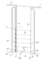
- FIG. 1 is a front view showing a door device according to Embodiment 1 of the present invention. It is an expansion perspective view which shows the door apparatus of FIG. It is an enlarged top view which shows the door apparatus of FIG.
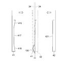
- FIG. 4 is an enlarged front view showing a guide member and a pressing member of FIG. 3.
- FIG. 13 is an enlarged front view showing a guide member and a holding member in a door device according to a second embodiment of the present invention.
- FIG. 13 is an enlarged front view showing a guide member and a holding member in a door device according to Embodiment 3 of the present invention.
- FIG. 13 is an enlarged front view showing a guide member and a pressing member in a door device according to Embodiment 4 of the present invention.
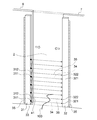
- FIG. 16 is an enlarged top view showing a door device according to Embodiment 6 of the present invention. It is an enlarged top view which shows the door apparatus by Embodiment 7 of this invention.
- FIG. 16 is an enlarged perspective view showing a door device according to Embodiment 8 of the present invention.
- FIG. 12 is an enlarged front view showing a guide member and a holding member of the door device of FIG. 11.
- 15 is a flowchart illustrating processing of a door control unit of a door device according to Embodiment 9 of the present invention.
- 15 is a flowchart showing processing of a door control unit of a door device according to Embodiment 10 of the present invention.
- FIG. 1 is a front view showing a door device according to Embodiment 1 of the present invention.
- FIG. 2 is an enlarged perspective view showing the door device of FIG.
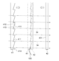
- FIG. 3 is an enlarged top view showing the door device of FIG.
- a car 1 is arranged in a hoistway of an elevator so as to be movable in the vertical direction.
- the car 1 is provided with a car doorway 2.
- a hanger case 3 arranged above the car entrance 2 and a car sill 4 arranged below the car entrance 2 are fixed to the car 1.
- the door rail 5 arranged along the width direction of the car doorway 2 is fixed to the hanger case 3.
- a first car door 6 and a second car door 7 for opening and closing the car entrance 2 are suspended.
- the first car door 6 and the second car door 7 are movable along the door rail 5 in the width direction of the car entrance 2.
- the car doorway 2 is opened and closed by the first car door 6 and the second car door 7 moving in the width direction of the car doorway 2.
- the hanger case 3 is provided with a door driving device 8 and a driven pulley 10.
- the door driving device 8 and the driven pulley 10 are arranged above the door rail 5.
- the door driving device 8 is a device that generates a driving force for moving the first car door 6 and the second car door 7.
- the drive shaft of the door drive device 8 is provided with a drive pulley 9.
- the drive pulley 9 rotates about the drive shaft of the door drive device 8 by the drive force of the door drive device 8.
- the drive pulley 9 and the driven pulley 10 are arranged apart from each other in the width direction of the car entrance 2.
- An endless transmission belt 11 is wound around the driving pulley 9 and the driven pulley 10. The transmission belt 11 moves according to the rotation of the driving pulley 9.
- the first car door 6 and the second car door 7 are individually connected to the transmission belt 11 via the connecting member 12. Thereby, the first car door 6 and the second car door 7 move in opposite directions according to the movement of the transmission belt 11.
- the car doorway 2 is opened and closed by the first car door 6 and the second car door 7 moving in opposite directions. Therefore, the door device according to the present embodiment is a double door system of an elevator.
- the car sill 4 is arranged along the width direction of the car doorway 2.
- a sill groove (not shown) is provided in the car sill 4 along the moving direction of the first car door 6 and the second car door 7.
- Each of the first car door 6 and the second car door 7 includes a door panel 25 that opens and closes the car doorway 2, a door hanger 26 provided at an upper end of the door panel 25, and a plurality of legs provided at a lower end of the door panel 25.
- the respective door panels 25 of the first car door 6 and the second car door 7 are arranged on a straight line along the width direction of the car entrance 2 when viewed from above.
- Each door hanger 26 of the first car door 6 and the second car door 7 is hung on the door rail 5.
- Each leg of the first car door 6 and the second car door 7 is inserted into a sill groove of the car sill 4.
- Each floor of the building is provided with a landing entrance 21 which is a space connecting the landing and the inside of the hoistway, as shown in FIG.
- a landing threshold (not shown) is provided below the landing entrance 21 along the width direction of the landing entrance 21.
- a first landing door 22 and a second landing door 23 for opening and closing the landing entrance 21 are provided.
- the first car door 6 faces the first hall door 22 in the depth direction of the car entrance 2 and the hall entrance 21.
- the second car door 7 faces the second hall door 23 in the depth direction of the car entrance 2 and the landing entrance 21.
- the first car door 6 moves together with the first landing door 22 and the second car door 7 moves together with the second landing door 23, so that the car entrance 2 and the The landing entrance 21 is simultaneously opened and closed.
- the sensor 33 is provided for each of the first car door 6 and the first car door 7.
- the sensor 33 includes a light emitting side sensor unit 31 as a first sensor unit and a light receiving side sensor unit 32 as a second sensor unit.
- the light emitting side sensor unit 31 is attached to a door closing side end of the door panel 25 of the first car door 6 by a sensor attaching member 35.
- the light emitting side sensor unit 31 is arranged along the height direction of the first car door 6 and the first landing door 22. Further, the light-emitting side sensor unit 31 is disposed between the first car door 6 and the first landing door 22 when viewed from above.
- the light-receiving-side sensor section 32 is attached to the door-closed end of the door panel 25 of the second car door 7 by a sensor attaching member 35.
- the light receiving side sensor unit 32 is disposed along the height direction of the second car door 7 and the second landing door 23.
- the light-receiving-side sensor unit 32 is disposed between the second car door 7 and the second landing door 23 when viewed from above.
- the sensor mounting member 35 for mounting the light receiving side sensor unit 32 to the second car door 7 is arranged separately from the sensor mounting member 35 for mounting the light emitting side sensor unit 31 to the first car door 6.
- the light emitting side sensor unit 31 includes a plurality of first light emitting units 311 and a housing that is a support member that supports the plurality of first light emitting units 311.
- the housing of the light-emitting side sensor unit 31 has a light-emitting unit installation surface provided with a plurality of first light-emitting units 311.
- the plurality of first light projecting units 311 are arranged at an interval in the height direction of the first car door 6 and the first landing door 22.
- the light-receiving-side sensor unit 32 has a plurality of first light-receiving units 321 and a housing that is a support member that supports the plurality of first light-receiving units 321.
- the housing of the light-receiving side sensor unit 32 has a light-receiving unit installation surface provided with a plurality of first light-receiving units 321.
- the plurality of first light receiving units 321 are arranged at an interval in the height direction of the second car door 7 and the second landing door 23.
- the light emitting side sensor part 31 and the light receiving side sensor part 32 are arranged in a state where the plurality of first light emitting parts 311 and the plurality of first light receiving parts 321 are individually opposed to each other in the width direction of the car entrance 2. .
- the width direction of each of the light emitting side sensor unit 31 and the light receiving side sensor unit 32 coincides with the depth direction of the car entrance 2 and the landing entrance 21.
- the position of the light emitting unit installation surface of the light emitting side sensor unit 31 is the same as the end face of the first car door 6 on the door closing side of the door panel 25 in the width direction of the car doorway 2.
- the position of the light receiving unit installation surface of the light receiving side sensor unit 32 is the same as the door closing side end surface of the door panel 25 of the second car door 7 in the width direction of the car entrance 2.
- a plurality of linear first beam paths each connecting the first light projecting unit 311 and each first light receiving unit 321 are provided between the light projecting side sensor unit 31 and the light receiving side sensor unit 32. It is set as a detection area. Therefore, the plurality of first beam paths are set at intervals in the vertical direction on an imaginary plane parallel to both the width direction and the vertical direction of the car doorway 2. The plurality of first beam paths are set between the car entrance 2 and the landing entrance 21 as shown in FIG.
- Each first light projecting unit 311 projects the beam 34 toward each first light receiving unit 321.
- the beam 34 emitted from each first light projecting unit 311 passes through each first beam path and is received by each first light receiving unit 321.
- the beam 34 passing through the first beam path including the object is blocked by the object.
- the sensor 33 does not detect an object.
- the sensor 33 detects the object by stopping the reception of the beam 34 by at least one of the plurality of first light receiving units 321. That is, the sensor 33 detects whether an object has entered the first detection area based on whether or not each of the first light receiving units 321 has received the beam 34. Therefore, in this example, the sensor 33 is a photoelectric sensor.
- the car 1 is provided with a door control unit 20 as shown in FIG.
- Information from the sensor 33 indicating whether an object has entered the first beam path, which is the first detection area, is sent from the light receiving side sensor unit 32 to the door control unit 20.
- the door control unit 20 controls the door driving device 8 based on information from the sensor 33.
- the door control unit 20 controls the movement of the first car door 6, the second car door 7, the first landing door 22, and the second landing door 23 by controlling the door driving device 8.
- the door control unit 20 sets the first car door 6, the second car Control is performed to reverse the moving direction of the door 7, the first landing door 22, and the second landing door 23 from the door closing direction to the door opening direction.
- a plate-like guide member 41 is fixed to the sensor mounting member 35 for mounting the light-emitting side sensor section 31 to the first car door 6.
- the guide member 41 is formed integrally with the sensor mounting member 35.
- the guide member 41 is disposed along the height direction of the first car door 6 and the first landing door 22, as shown in FIG. Further, the guide member 41 is disposed in a range in the height direction of the first car door 6 and the first landing door 22.
- the guide member 41 may be disposed in the entire height range of the first car door 6 and the first landing door 22, or may be arranged in the height direction of the first car door 6 and the first landing door 22. May be arranged only in a part of.
- the position of the lower end surface of the guide member 41 coincides with the position of the lower surface of the door panel 25 of the first car door 6 in the vertical direction. Further, in this example, the position of the upper end surface of the guide member 41 is lower than the position of the upper end surface of the door panel 25 of the first car door 6.
- the guide member 41 is disposed between the door panel 25 of the first car door 6 and the light-emitting side sensor unit 31 as shown in FIG.
- the door closing side end of the guide member 41 protrudes toward the door closing side from the light emitting unit installation surface of the light emitting side sensor unit 31. Further, the position of the door closing side end of the guide member 41 is a position that does not protrude to the door closing side from the door closing side end surface of the first landing door 22.
- a plate-shaped pressing member 42 is fixed to the sensor mounting member 35 for mounting the light receiving side sensor unit 32 to the second car door 7.
- the pressing member 42 is formed integrally with the sensor mounting member 35.
- the holding member 42 is arranged along the height direction of the second car door 7 and the second landing door 23.
- the holding member 42 is arranged in a range in the height direction of the second car door 7 and the second landing door 23.
- the holding member 42 may be arranged in the entire height range of the second car door 7 and the second landing door 23, or may be arranged in the height direction of the second car door 7 and the second landing door 23. May be arranged only in a part of.
- the position of the lower end surface of the pressing member 42 coincides with the position of the lower end surface of the guide member 41 in the vertical direction.
- the position of the upper end surface of the pressing member 42 coincides with the position of the upper end surface of the guide member 41 in the vertical direction.
- the pressing member 42 is disposed between the door panel 25 of the second car door 7 and the light receiving side sensor unit 32.
- the door-closed end of the pressing member 42 protrudes toward the door-closed side from the light-receiving unit installation surface of the light-receiving sensor 32.
- a vertical surface 421 extending in the vertical direction is formed at the door closing end of the pressing member 42.
- the position of the up-down direction surface 421 of the holding member 42 is closer to the door opening side than the end surface of the second landing door 23 on the door closing side.
- the holding member 42 is arranged at a position displaced in the depth direction of the car entrance 2 and the landing entrance 21 with respect to the guide member 41. Thereby, even if the 1st car door 6, the 2nd car door 7, the 1st hall door 22, and the 2nd hall door 23 reach the fully closed position which fully closes the car doorway 2 and the hall doorway 21, the holding member is also provided. 42 does not interfere with the guide member 41. In a state where the first car door 6, the second car door 7, the first landing door 22, and the second landing door 23 are in the fully closed position, a part of the door closing side end of the guide member 41 is connected to the car entrance 2 and the landing. In the depth direction of the entrance 21, it overlaps with the door closing side end of the holding member 42.
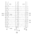
- FIG. 4 is an enlarged front view showing the guide member 41 and the pressing member 42 of FIG.
- a plurality of first recesses 411 are formed at the door-closing end of the guide member 41 and are arranged in the up-down direction. Each position of the plurality of first recesses 411 in the up-down direction is set in accordance with each position of the plurality of first beam paths.
- a first guide surface 412 and second guide surfaces 413 and 414 connected to the first guide surface 412 are formed on the inner surface of each first recess 411.
- Each first guide surface 412 is an inclined surface inclined with respect to the horizontal.
- Each of the first guide surfaces 412 is inclined toward the door opening side of the first car door 6 from the upper end to the lower end of the first guide surface 412.
- the second guide surface 413 formed on the inner surface of each of the first recesses 411 other than the first recess 411 at the lowermost position is horizontally moved from the lower end of the first guide surface 412 to the door closing side of the first car door 6. It is a horizontal plane that extends.
- the second guide surface 414 formed on the inner surface of the first concave portion 411 at the lowermost position is inclined downward from the lower end of the first guide surface 412 toward the door closing side of the first car door 6. Plane. Therefore, a lowermost second guide surface 414 is formed at the lower end of the guide member 41 as a lower end inclined surface.
- first guide surface 412 and the second guide surface 413 are formed alternately and continuously upward at the door-closed end of the guide member 41 from the upper end of the second guide surface 414 at the lowest position. ing.
- the position of each first beam path corresponding to each first recess 411 is set based on the boundary between the first guide surface 412 and the second guide surfaces 413, 414.
- the long object 100 may be a string, a rod, or the like.
- the guide member 41 moves the long object 100 straddling the car doorway 2 and the landing doorway 21 by moving together with the first car door 6 and the first landing door 22 in a direction in which the car doorway 2 and the landing doorway 21 close. It is guided to a first beam path, which is one detection area.
- the guide member 41 guides the long object 100 along the first guide surface 412, and moves the long object 100 downward toward the boundary between the first guide surface 412 and the second guide surfaces 413, 414. Lead to.
- the guide member 41 guides the elongated object 100 along the second guide surface 414 at the lowermost position, and is elongated toward the boundary between the first guide surface 412 and the second guide surface 414.
- the object 100 is guided upward.
- the long object 100 that has reached one of the boundary between the first guide surface 412 and the second guide surface 413 and the boundary between the first guide surface 412 and the second guide surface 414 is the first object through which the beam 34 passes. Enter one beam path.
- the pressing member 42 presses the long object 100 by the guide member 41. Thereby, when the respective states of the car doorway 2 and the landing doorway 21 are in the fully closed state, the long object 100 is held between the guide member 41 and the pressing member 42.
- the door devices include a hanger case 3, a car sill 4, a door rail 5, a first car door 6, a second car door 7, a door driving device 8, a driving pulley 9, a driven pulley 10, a transmission belt 11, a connecting member 12, It has a door control unit 20, a landing threshold, a first landing door 22, a second landing door 23, an engagement device 24, a sensor 33, a sensor mounting member 35, a guide member 41, and a holding member 42.
- the long object 100 does not stay on the upper surface of the car sill 4 but on the second guide surface 414 at the lowest position.
- the beam 34 passing through the first beam path is blocked by the object 100, and the long object 100 is detected by the sensor 33.
- the long object 100 When the long object 100 straddles the car doorway 2 and the landing doorway 21 in the air away from the car threshold 4, the first car door 6, the second car door 7, the first landing door 22 and When the closing operation of the second landing door 23 is started, the long object 100 comes into contact with the first guide surface 412.
- the long object 100 does not stay between the two first beam paths and follows the first guide surface 412. To the first beam path below. Thereby, the beam 34 passing through the first beam path is blocked by the object 100, and the long object 100 is detected by the sensor 33.
- the guide member 41 is disposed between the first car door 6 and the first landing door 22.
- the guide member 41 is arranged in a range in the height direction of the first car door 6 and the first landing door 22 without the guide member 41 interfering with each of the first car door 6 and the first landing door 22. be able to.
- the object 100 can be more reliably guided to the first beam path of the sensor 33 by the guide member 41. Therefore, the object 100 straddling between the car entrance 2 and the landing entrance 21 can be detected more reliably.
- the long object 100 can be guided by the guide member 41 to the first beam path of the sensor 33. Therefore, the number of first beam paths of the sensor 33 can be reduced, and the first detection area of the sensor 33 can be reduced. Thereby, the cost of the sensor 33 can be reduced.
- the guide member 41 is disposed between the first car door 6 and the light-emitting side sensor unit 31. For this reason, the guide member 41 can be arranged in the gap between the first car door 6 and the light emitting side sensor unit 31, and the guide member 41 can be easily attached to the existing first car door 6. That is, by disposing the guide member 41 between the first car door 6 and the light emitting side sensor section 31, it is possible to prevent the installation space of the guide member 41 from increasing toward the landing. Thereby, the guide member 41 can be easily attached to the existing first car door 6 while maintaining the distance between the car entrance 2 and the landing entrance 21.
- the pressing member 42 is disposed between the second car door 7 and the light-receiving-side sensor unit 32. For this reason, the pressing member 42 can be arranged in the gap between the second car door 7 and the light receiving side sensor unit 32, and the pressing member 42 can be easily attached to the existing second car door 7.
- the guide member 41 is provided on the sensor mounting member 35 for mounting the light emitting side sensor unit 31 to the first car door 6. For this reason, the guide member 41 and the sensor mounting member 35 can be handled as an integral part. Thereby, the number of parts can be reduced. In addition, the work of adjusting the positional relationship between the light emitting side sensor unit 31 and the guide member 41 can be facilitated. Therefore, it is possible to reduce the burden on the manufacturing operation of the door device, and it is possible to reduce the manufacturing cost.
- the pressing member 42 is provided on the sensor mounting member 35 for mounting the light-receiving-side sensor unit 32 to the second car door 7. For this reason, the pressing member 42 and the sensor mounting member 35 can be handled as an integral part. Thereby, the number of parts can be reduced. In addition, the operation of adjusting the positional relationship between the light receiving side sensor unit 32 and the pressing member 42 can be facilitated. Therefore, it is possible to reduce the burden on the manufacturing operation of the door device, and it is possible to reduce the manufacturing cost.
- the pressing member 42 is arranged at a position displaced in the depth direction of the car doorway 2 and the landing doorway 21 with respect to the guide member 41. For this reason, it is possible to more reliably press the long object 100 on the guide member 41 by the pressing member 42 while avoiding the pressing member 42 from interfering with the guide member 41.
- the guide member 41 has a first guide surface 412 that guides the long object 100 to the first beam path below. For this reason, the long object 100 can be guided in a direction that does not oppose the gravity applied to the long object 100, and guidance of the long object 100 to the first beam path can be further ensured.
- a second guide surface 414 at a lowermost position for guiding the elongated object 100 to the upper first beam path is formed. For this reason, it is easy to set the long object 100 without setting the first beam path at the height of the lower surface of the first car door 6 and the second car door 7 for which it is difficult to set the first beam path. And it can detect more reliably.
- Embodiment 2 FIG.
- the up-down direction surface 421 along the up-down direction is formed at the door closing side end of the holding member 42.
- a plurality of second concave portions may be formed at the door closing end of the holding member 42.
- FIG. 5 is an enlarged front view showing the guide member 41 and the pressing member 42 in the door device according to Embodiment 2 of the present invention.
- a plurality of second concave portions 422 arranged in the up-down direction are formed at the door closing side end of the pressing member 42.
- the respective positions of the plurality of second recesses 422 in the vertical direction are set in accordance with the respective positions of the plurality of first beam paths.
- first pressing surface 423 and second pressing surfaces 424 and 425 connected to the first pressing surface 423 are formed on the inner surface of each second concave portion 422.
- the first pressing surface 423 is an inclined surface inclined with respect to the horizontal.
- the first pressing surface 423 is inclined from the upper end to the lower end of the first pressing surface 423 toward the door opening side of the second car door 7.
- the second pressing surface 424 formed on the inner surface of each of the second concave portions 422 other than the lowermost second concave portion 422 is horizontally moved from the lower end of the first pressing surface 423 to the door closing side of the second car door 7. It is a horizontal plane that extends.
- the second pressing surface 425 formed on the inner surface of the second concave portion 422 at the lowermost position is inclined downward from the lower end of the first pressing surface 423 toward the door closing side of the second car door 7. Plane. Therefore, the lowermost second pressing surface 425 is formed at the lower end of the pressing member 42 as a lower end inclined surface.
- the first pressing surface 423 and the second pressing surface 424 are continuously formed alternately upward from the upper end of the second pressing surface 425 at the lowest position. ing.
- the position of each first beam path corresponding to each second recess 422 is set based on the boundary between the first pressing surface 423 and the second pressing surfaces 424, 425.
- the pressing member 42 presses the long object 100 by the guide member 41 as shown in FIG.
- the long object 100 is sandwiched between the first recess 411 and the second recess 422.
- the long object 100 is held between the guide member 41 and the pressing member 42.
- Other configurations are the same as in the first embodiment.
- the first recess 411 is formed in the guide member 41, and the second recess 422 is formed in the pressing member 42.
- the long object 100 can be sandwiched between the first recess 411 and the second recess 422, and the long object 100 is guided to the first beam path by each of the guide member 41 and the holding member 42. Can be.
- the long object 100 can be more reliably guided to the first beam path, which is the first detection area, and the long object 100 can be detected more reliably.
- the light emitting side sensor unit 31 is provided on the first car door 6 and the light receiving side sensor unit 32 is provided on the second car door 7.
- the light emitting side sensor unit 31 may be provided on the first landing door 22 and the light receiving side sensor unit 32 may be provided on the second landing door 23.
- a guide member 41 is provided on a sensor mounting member for attaching the light emitting side sensor unit 31 to the first landing door 22, and a pressing member 42 is provided on a sensor mounting member for attaching the light receiving side sensor unit 32 to the second landing door 23.
- the guide member 41 is disposed between the light-emitting side sensor unit 31 and the first landing door 22.
- the pressing member 42 is disposed between the light receiving side sensor unit 32 and the second landing door 23.
- the sensor 33 that detects the long object 100 is a photoelectric sensor.
- the sensor that detects the long object 100 may be a camera.
- FIG. 6 is an enlarged front view showing the guide member 41 and the pressing member 42 in the door device according to Embodiment 3 of the present invention.
- a camera (not shown) is arranged between the car entrance 2 and the landing entrance 21 as a sensor.
- the camera is provided on the first car door 6.
- the camera is arranged at the position of the light emitting side sensor unit 31 of the first embodiment.
- the detection area of the camera is a first detection area along the moving direction of the first car door 6 and the first landing door 22, that is, the width direction of the car entrance 2 and the landing entrance 21.
- the detection area of the camera is a band-shaped area having a set width D in the vertical direction. The camera detects the long object 100 when the object 100 enters the detection area of the camera.
- An upper guide surface 415 and a lower guide surface 416 that are vertically separated from each other and an intermediate surface 417 that connects the upper guide surface 415 and the lower guide surface 416 to each other are formed at the door closing side end of the guide member 41. I have.
- the upper guide surface 415 is formed at the upper end of the guide member 41.
- the upper guide surface 415 is inclined toward the door opening side of the first car door 6 from the upper end to the lower end of the upper guide surface 415.
- the lower guide surface 416 is formed at the lower end of the guide member 41. Further, the lower guide surface 416 is inclined toward the door opening side of the first car door 6 from the lower end to the upper end of the lower guide surface 416.
- the intermediate surface 417 is a surface connecting the lower end of the upper guide surface 415 and the upper end of the lower guide surface 416.
- the intermediate surface 417 extends along the up-down direction.
- the vertical positions of the upper guide surface 415, the lower guide surface 416, and the intermediate surface 417 are set in accordance with the detection area of the camera.
- the position of the upper guide surface 415 is set at a position deviated upward from the detection area of the camera.
- the position of the lower guide surface 416 is set at a position deviated downward from the detection area of the camera.
- the position of the intermediate plane 417 is set within the detection area of the camera.
- the guide member 41 moves in a direction in which the car doorway 2 and the landing doorway 21 are closed, so that the long object 100 is moved to the upper guide surface 415.
- the light is guided to the detection area of the camera along the lower guide surface 416.
- a camera is used as a sensor for detecting the long object 100.
- a pressure-sensitive sensor may be used as a sensor for detecting the long object 100.
- the first detection area which is the detection area of the pressure-sensitive sensor, is the area of the pressure-sensitive surface set for the pressure-sensitive sensor.
- the pressure sensor is attached to the intermediate surface 417 of the guide member 41. Even in this case, the long object 100 can be guided to the detection area of the pressure-sensitive sensor, and the long object 100 can be detected more reliably.
- the pressure sensor only needs to be disposed at a position where the long object 100 guided by the guide member 41 contacts. Therefore, the pressure-sensitive sensor may be attached to the first car door 6 instead of the guide member 41, for example.
- the first detection region of the sensor is a region along the width direction of the car entrance 2 and the landing entrance 21.
- the first detection region of the sensor may be a region along the vertical direction.
- FIG. 7 is an enlarged front view showing the guide member 41 and the pressing member 42 in the door device according to Embodiment 4 of the present invention.
- a sensor that detects the long object 100 is a photoelectric sensor.
- the configuration of the photoelectric sensor according to the present embodiment is the same as the configuration of the sensor 33 according to the first embodiment.
- a plurality of first beam paths through which the sensor beam 34 passes are set along the vertical direction.
- the light emitting side sensor section which is the first sensor section included in the sensor, is provided in the hanger case 3.
- the light-receiving-side sensor unit, which is the second sensor unit included in the sensor, is provided on the side surface in the width direction of the car sill 4.
- the first beam path of the sensor that is, the first detection area, is set only in the central area in the width direction of the car entrance 2 and the landing entrance 21.
- Other configurations are the same as those of the third embodiment.
- the guide member 41 moves in a direction in which the car doorway 2 and the landing doorway 21 are closed, so that the long object 100 is moved to the upper guide surface 415.
- the light is guided to the first detection area of the sensor along the lower guide surface 416.
- the pressing member 42 presses the long object 100 by the guide member 41 as shown in FIG.
- the long object 100 is held between the guide member 41 and the pressing member 42 in the first detection area of the sensor.
- the guide member 41 moves in the direction in which the car entrance 2 and the landing entrance 21 are closed, The long object 100 can be guided to the first detection area of the sensor. Thereby, the long object 100 can be detected more reliably.
- a camera may be used as a sensor for detecting the object 100.
- the camera is attached to the hanger case 3.
- a camera may be mounted above the landing entrance 21.
- the sensors for detecting the object 100 are attached to the hanger case 3 and the car sill 4.
- sensors for detecting the object 100 may be attached to the upper and lower portions of the landing entrance 21.
- FIG. FIG. 8 is an enlarged top view showing a door device according to Embodiment 5 of the present invention.
- the guide member 41 is attached to the door panel 25 of the first car door 6 by a component attaching member 51.
- the component attachment member 51 for attaching the guide member 41 to the first car door 6 is a separate member from the sensor attachment member 35 for attaching the light emitting side sensor unit 31 to the first car door 6.
- the guide member 41 is disposed between the light emitting side sensor unit 31 and the first landing door 22.
- the holding member 42 is attached to the door panel 25 of the second car door 7 by the component attaching member 51.
- the component attachment member 51 for attaching the holding member 42 to the second car door 7 is a separate member from the sensor attachment member 35 for attaching the light receiving side sensor 32 to the second car door 7.
- the pressing member 42 is disposed between the light receiving side sensor unit 32 and the second landing door 23.
- the holding member 42 is arranged at a position displaced in the depth direction of the car entrance 2 and the landing entrance 21 with respect to the guide member 41. Thereby, even when the state of the car doorway 2 and the landing doorway 21 is in the fully closed state, the pressing member 42 does not interfere with the guide member 41.
- Other configurations are the same as in the first embodiment.
- the guide member 41 is disposed between the light emitting side sensor unit 31 and the first landing door 22. For this reason, the guide member 41 can be easily arranged avoiding the light emitting side sensor unit 31. Further, the lower portion of the guide member 41 can be inserted into a gap between the car threshold 4 and the landing threshold. Thereby, even when the long object 100 straddling the car entrance 2 and the landing entrance 21 is placed on the car threshold 4 and the landing threshold, the long object 100 is more reliably guided to the first detection area of the sensor 33. Can be. Further, the distance from each of the first car door 6 and the first landing door 22 to the guide member 41 can be easily adjusted. Thereby, the guide member 41 can be made difficult to see from the passengers inside the car 1 and at the landing.
- the pressing member 42 is disposed between the light-receiving-side sensor unit 32 and the second landing door 23. For this reason, the pressing member 42 can be easily arranged avoiding the light receiving side sensor unit 32. Further, the lower part of the holding member 42 can be inserted into a gap between the car threshold 4 and the landing threshold. Thus, the long object 100 guided to the first detection area of the sensor 33 by the guide member 41 can be held more reliably. Further, the distance from each of the second car door 7 and the second landing door 23 to the pressing member 42 can be easily adjusted. This makes it possible to make the pressing member 42 invisible to the passengers inside the car 1 and at the landing.
- the light emitting side sensor unit 31 is provided on the first car door 6 and the light receiving side sensor unit 32 is provided on the second car door 7.
- the light emitting side sensor unit 31 may be provided on the first landing door 22 and the light receiving side sensor unit 32 may be provided on the second landing door 23.
- the guide member 41 is attached to the first landing door 22 by the component attachment member 51
- the pressing member 42 is attached to the second landing door 23 by the component attachment member 51.
- a guide member 41 is disposed between the light emitting side sensor unit 31 and the first car door 6, and a pressing member 42 is disposed between the light receiving side sensor unit 32 and the second car door 7. .
- the component mounting member 51 is a separate member from the sensor mounting member 35.
- the component mounting member 51 may be a single material integrated with the sensor mounting member 35. In this case, the number of components can be reduced, and the manufacturing cost of the door device can be reduced.
- FIG. 9 is an enlarged top view showing a door device according to Embodiment 6 of the present invention.
- the guide member 41 is provided in the light emitting side sensor unit 31. Further, the guide member 41 is attached to the light emitting unit installation surface, avoiding each of the first light emitting units 311. Further, the guide member 41 is disposed within a range in the width direction of the light emitting side sensor unit 31 when viewed from above. That is, the guide member 41 is arranged within the range of the light-emitting side sensor unit 31 in the depth direction of the car entrance 2 and the landing entrance 21. In this example, the guide member 41 is a separate member from the housing of the light emitting side sensor unit 31.
- the pressing member 42 is provided in the light receiving side sensor unit 32.
- the pressing member 42 is attached to the light receiving unit installation surface, avoiding each of the first light receiving units 321.
- the holding member 42 is disposed within a range in the width direction of the light receiving side sensor unit 32 when viewed from above. That is, the holding member 42 is disposed within the range of the light receiving side sensor unit 32 in the depth direction of the car entrance 2 and the landing entrance 21.
- the pressing member 42 is a separate member from the housing of the light receiving side sensor unit 32.
- the holding member 42 is arranged at a position displaced in the depth direction of the car entrance 2 and the landing entrance 21 with respect to the guide member 41. Thereby, even when the state of the car doorway 2 and the landing doorway 21 is in the fully closed state, the pressing member 42 does not interfere with the guide member 41.
- Other configurations are the same as in the first embodiment.
- the guide member 41 is provided in the light emitting side sensor unit 31.
- the guide member 41 can be arranged within the range in the width direction of the light emitting side sensor unit 31.
- the guide member 41 is a separate member from the housing of the light emitting side sensor unit 31.
- the housing of the light emitting side sensor unit 31 and the guide member 41 may be formed of a single material. In this way, the light emitting side sensor 31 and the guide member 41 can be simultaneously attached to the first car door 6, and the work of attaching the light emitting side sensor 31 and the guide member 41 can be facilitated.
- the pressing member 42 is a separate member from the housing of the light receiving side sensor unit 32.
- the housing of the light receiving side sensor unit 32 and the pressing member 42 may be formed of a single material. With this configuration, the light receiving side sensor 32 and the pressing member 42 can be simultaneously attached to the second car door 7, and the work of mounting the light receiving side sensor 32 and the pressing member 42 can be facilitated.
- the light emitting side sensor unit 31 is provided on the first car door 6.
- the light emitting side sensor unit 31 may be provided on the first landing door 22.
- the light-receiving-side sensor unit 32 is provided on the second car door 7.
- the light receiving side sensor unit 32 may be provided on the second landing door 23.
- FIG. FIG. 10 is an enlarged top view showing a door device according to Embodiment 7 of the present invention.
- the guide member 41 is disposed between the first car door 6 and the light emitting side sensor unit 31.
- the guide member 41 is attached to the door panel 25 of the first car door 6 in the same manner as in the first embodiment. That is, the guide member 41 is attached to the first car door 6 by the sensor attaching member 35 to which the light emitting side sensor unit 31 is attached.
- the holding member 42 is disposed between the second landing door 23 and the light receiving side sensor unit 32.
- the holding member 42 is attached to the door panel 25 of the second car door 7 in the same manner as in the fifth embodiment. That is, the pressing member 42 is attached to the door panel 25 of the second car door 7 by a component attaching member 51 separate from the sensor attaching member 35.
- the guide member 41 and the pressing member 42 are disposed on the opposite sides with respect to a straight line connecting the light emitting side sensor unit 31 and the light receiving side sensor unit 32, that is, the linear first beam path. ing.
- Other configurations are the same as in the first embodiment.
- the guide member 41 and the pressing member 42 are arranged on opposite sides with respect to a straight line connecting the light emitting side sensor unit 31 and the light receiving side sensor unit 32. For this reason, when the state of the car doorway 2 and the landing doorway 21 is in the fully closed state, the interference between the pressing member 42 and the guide member 41 can be more reliably prevented. Further, a first beam path can be set between the guide member 41 and the holding member 42. Therefore, the long object 100 can be guided to the first beam path of the sensor between the guide member 41 and the holding member 42. Thereby, the long object 100 can be detected more reliably.
- the guide member 41 is disposed between the light-emitting side sensor section 31 and the first car door 6, and the pressing member 42 is disposed between the light-receiving side sensor section 32 and the second landing door 23.
- the positional relationship between the guide member 41 and the pressing member 42 is not limited to this.
- the guide member 41 and the pressing member 42 are disposed on opposite sides with respect to a straight line connecting the light emitting side sensor unit 31 and the light receiving side sensor unit 32, the light emitting side sensor unit 31
- the guide is guided to one of a position between the first car door 6 and the first car door 6, a position within a range in the width direction of the light emitting side sensor unit 31, and a position between the light emitting side sensor unit 31 and the first landing door 22.
- the member 41 can be arranged. Further, a position between the light receiving side sensor unit 32 and the second car door 7, a position within a range in the width direction of the light receiving side sensor unit 32, and a position between the light receiving side sensor unit 32 and the second landing door 23.
- the holding member 42 can be arranged at any of the positions.
- FIG. 11 is an enlarged perspective view showing a door device according to Embodiment 8 of the present invention.
- FIG. 12 is an enlarged front view showing a guide member and a pressing member of the door device of FIG.
- the light emitting side sensor unit 31 includes a plurality of first light emitting units 311, a plurality of second light emitting units 312, and a housing in which each of the first light emitting units 311 and each of the second light emitting units 312 are installed. have.
- the configuration of the housing of the light emitting side sensor unit 31 is the same as that of the first embodiment.
- the plurality of first light emitting units 311 and the plurality of second light emitting units 312 are provided on the light emitting unit installation surface of the housing.
- the plurality of first light projecting units 311 are arranged at an interval in the height direction of the first car door 6 and the first landing door 22.
- the plurality of second light emitting units 312 are arranged at an interval in the height direction of the first car door 6 and the first landing door 22.
- the first light emitting units 311 and the second light emitting units 312 are alternately arranged in the height direction of the first car door 6 and the first landing door 22.
- the light receiving side sensor unit 32 includes a plurality of first light receiving units 321, a plurality of second light receiving units 322, and a housing in which each of the first light receiving units 321 and each of the second light receiving units 322 are installed. .
- the configuration of the housing of the light receiving side sensor unit 32 is the same as that of the first embodiment.
- the plurality of first light receiving units 321 and the plurality of second light receiving units 322 are provided on a light receiving unit installation surface of a common housing.
- the plurality of first light receiving units 321 are arranged at an interval in the height direction of the second car door 7 and the second landing door 23.
- the plurality of second light receiving units 322 are arranged at an interval in the height direction of the second car door 7 and the second landing door 23.
- the first light receiving units 321 and the second light receiving units 322 are alternately arranged in the height direction of the second car door 7 and the second landing door 23.
- the plurality of first light emitting units 311 and the plurality of first light receiving units 321 individually face each other in the width direction of the car entrance 2.
- the plurality of second light emitting units 312 and the plurality of second light receiving units 322 individually face each other in the width direction of the car entrance 2.
- Each first beam path is set as a first detection area.
- Each second beam path is set as a second detection area at a position different from each first detection area.
- a plurality of first beam paths and a plurality of second beam paths are alternately arranged in the vertical direction.
- each first beam path with respect to the guide member 41 is set based on the boundary between the first guide surface 412 and the second guide surfaces 413 and 414 as in the first embodiment.
- the vertical position of each second beam path with respect to the guide member 41 is set at a position farther from the boundary between the first guide surface 412 and the second guide surfaces 413 and 414 than the position of the first beam path. .
- Each first light projecting unit 311 projects the beam 34 toward each first light receiving unit 321.
- the beam 34 emitted from each first light projecting unit 311 passes through each first beam path and is received by each first light receiving unit 321.
- Each second light projecting unit 312 projects the beam 36 toward each second light receiving unit 322.
- the beam 36 emitted from each second light projecting unit 312 passes through each second beam path and is received by each second light receiving unit 322.
- the functions of the sensor 33 include a first sensor function for detecting an object entering the first beam path and a second sensor function for detecting an object entering the second beam path. Therefore, the first sensor function of the sensor 33 is a function of detecting an object by the first light projecting unit 311 and the first light receiving unit 321. The second sensor function of the sensor 33 is a function of detecting an object by the second light emitting unit 312 and the second light receiving unit 322.
- the lower limit of the size of the object that can be detected by the first sensor function is smaller than the lower limit of the size of the object that can be detected by the second sensor function. That is, the sensor 33 can detect an object whose first sensor function is smaller than that of the second sensor function.
- the sensor 33 detects a thin and long object 100 by a first sensor function, and detects a large object by a second sensor function. As the large object, a person, luggage, and the like can be considered.
- the diameter of the beam 34 emitted from each of the first light projecting units 311 is narrowed to be smaller than the diameter of the beam 36 emitted from each of the second light projecting units 312.
- the intensity of the beam 34 emitted from the first light projecting unit 311 is adjusted to be different from the intensity of the beam 36 emitted from the second light projecting unit 312.
- the light receiving sensitivity of the first light receiving unit 321 is adjusted to be different from the light receiving sensitivity of the second light receiving unit 322.
- the beam 34 passing through the first beam path including the object 100 is blocked by the object 100. Thereby, the long object 100 is detected by the sensor 33.
- the beam 36 passing through the second beam path containing the large object is blocked by the object. Thereby, a large object is detected by the sensor 33.
- the sensor 33 sends information indicating whether the object is detected by the first sensor function and the second sensor function to the door control unit 20.
- the door control unit 20 determines whether the first car door 6, the second car door 7, the first landing door 22, and the second landing door 23 are based on the detection of an object by each of the first sensor function and the second sensor function. Control movement. Other configurations are the same as in the first embodiment.
- the lower limit of the size of the object that can be detected by the first sensor function is smaller than the lower limit of the size of the object that can be detected by the second sensor function. For this reason, a thin long object such as a string and a large object such as a human can be distinguished and detected, and different control can be performed according to each of the thin long object and the large object. . Further, the long object 100 guided to the first beam path by the guide member 41 can be more reliably detected by the first sensor function.
- a plurality of first beam paths and a plurality of second beam paths are respectively set between the light emitting side sensor unit 31 and the light receiving side sensor unit 32.
- the sensor 33 can have two types of functions, the first sensor function and the second sensor function, by one combination of the light emitting side sensor unit 31 and the light receiving side sensor unit 32. This makes it possible to prevent the sensor 33 from having two types of functions and to prevent the light-emitting side sensor unit 31 and the light-receiving side sensor unit 32 from increasing the installation space.
- Embodiment 9 FIG.
- the configuration of the door device according to the present embodiment is the same as the configuration of the eighth embodiment shown in FIGS. 11 and 12 except for the control of the door control unit 20.
- the movement section from the fully open position to the fully closed position of the first car door 6, the second car door 7, the first landing door 22, and the second landing door 23, that is, the opening and closing movement section, is a detection section of the first sensor function.
- a detection section of the second sensor function is set closer to the door than the detection section of the second sensor function.
- the detection section of the first sensor function is a section of 20 mm from the fully closed position to the door opening side.
- the detection section of the second sensor function is a section obtained by removing the detection section of the first sensor function from the opening and closing movement section of the door.
- the door control unit 20 determines whether the first car door 6, the second car door 7, or the first landing door is based on whether an object is detected by the first sensor function. 22 and the movement of the second landing door 23 are controlled. Further, when a door is present in the detection section of the second sensor function, the door control unit 20 determines whether the first car door 6, the second car door 7, the first car door 7, The movement of the landing door 22 and the second landing door 23 is controlled. That is, the door control unit 20 performs one of the first sensor function and the second sensor function based on the positions of the first car door 6, the second car door 7, the first landing door 22, and the second landing door 23. The movement of the first car door 6, the second car door 7, the first landing door 22, and the second landing door 23 is controlled based on the information on whether or not an object is detected by the selected function.
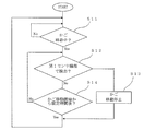
- FIG. 13 is a flowchart showing processing of the door control unit of the door device according to Embodiment 9 of the present invention.
- the door control unit 20 determines whether or not the position of the door is at the fully open position in step S1.
- step S1 If it is determined in step S1 that the door position is not at the fully open position, the door control unit 20 repeats the determination whether the door position is at the fully open position. On the other hand, if it is determined in step S1 that the position of the door is at the fully open position, the process proceeds to step S2.
- step S2 the door control unit 20 determines whether an object is detected by the second sensor function of the sensor 33.
- step S2 If it is determined in step S2 that an object has been detected by the second sensor function, the process proceeds to step S3. On the other hand, if no object is detected by the second sensor function in step S2, the process proceeds to step S4.
- step S3 the door control unit 20 performs the door opening operation. Thereafter, the process returns to step S1.
- step S4 the door control unit 20 starts the door closing operation. Thereafter, the process proceeds to step S5.
- step S5 the door control unit 20 determines whether or not the position of the door is within the detection section of the first sensor function.
- step S5 If it is determined in step S5 that the position of the door is not within the detection section of the first sensor function, the process returns to step S2. As a result, the door control unit 20 repeats the processes of step S2, step S4, and step S5 until the position of the door enters the detection section of the first sensor function.
- step S5 If it is determined in step S5 that the position of the door is within the detection section of the first sensor function, the process proceeds to step S6.
- step S6 the door control unit 20 determines whether an object is detected by the first sensor function of the sensor 33.
- step S6 If it is determined in step S6 that an object has been detected by the first sensor function, the process proceeds to step S3. Thus, the door control unit 20 controls the opening operation of the door by reversing the movement of the door. On the other hand, if it is determined in step S6 that the object has not been detected by the first sensor function, the process proceeds to step S7.
- step S7 the door control unit 20 determines whether the position of the door is the fully closed position. If it is determined that the position of the door is not at the fully closed position, the process returns to step S6. Thereby, the door control unit 20 repeats the processing of step S6 and the processing of step S7 until the position of the door reaches the fully closed position. On the other hand, when it is determined that the position of the door is the fully closed position, the process returns to step S1.
- one of the first sensor function and the second sensor function of the sensor 33 is selected based on the position of the door, and the door function is selected based on the information on the presence or absence of the detection of the object by the selected function. Movement is controlled. Therefore, for example, the long object 100 can be detected by the first sensor function of the sensor 33 at a door position where a large object is unlikely to pass through the car entrance 2 and the landing entrance 21. Thereby, the malfunction of the sensor 33 can be reduced.
- the length of the detection section of the first sensor function and the length of the detection section of the second sensor function are fixed lengths.
- the length of the detection section of the first sensor function and the length of the detection section of the second sensor function may be respectively variable.
- a part of the detection section of the first sensor function may overlap with the detection section of the second sensor function.
- one of the first sensor function and the second sensor function of the sensor 33 is selected based on the position of the door, and the control of the door control unit 20 is performed based on the selected function.
- the detection condition for the sensor 33 to detect an object by the first sensor function may be different from the detection condition for the sensor 33 to detect the object by the second sensor function.
- the time required from when the object enters the first beam path until the object is detected by the first sensor function, and the time required after the object enters the second beam path and the object is detected by the second sensor function. Time may be different from each other.
- the number of beams 34 blocked by the object for detecting the object by the first sensor function and the number of beams 36 blocked by the object for detecting the object by the second sensor function are different from each other. You may.
- the detection condition for the sensor 33 to detect the object by the first sensor function and the detection condition for the sensor 33 to detect the object by the second sensor function are different from each other, so that the malfunction of the sensor 33 is reduced. be able to.
- Embodiment 10 FIG.
- the configuration of the door device according to the present embodiment is the same as the configuration of the first embodiment except for the control of the door control unit 20.
- Information from the door control unit 20 is sent to an elevator control device that controls the operation of the elevator.
- the elevator control device controls the movement of the car 1 based on the information from the door control unit 20.
- the door control unit 20 outputs a door fully closed signal to the elevator control device when the car entrance 2 and the landing entrance 21 are completely closed.
- the door fully closed signal from the door control unit 20 is sent to the elevator control device, the car 1 can be moved under the control of the elevator control device.
- the door control unit 20 When the sensor 33 detects the long object 100 after the movement of the car 1 is started under the control of the elevator control device, the door control unit 20 outputs a stop signal for stopping the car to the elevator control device. When a stop signal from the door control unit 20 is sent to the elevator control device, the car 1 is emergency stopped under the control of the elevator control device.
- FIG. 14 is a flowchart showing processing of the door control unit of the door device according to Embodiment 10 of the present invention.
- the door control unit 20 determines whether the car 1 is moving based on information from the elevator control device.
- step S11 If it is determined in step S11 that the car 1 has not moved, the door control unit 20 repeats the determination whether the car 1 has moved. On the other hand, if it is determined in step S11 that the car 1 is moving, the process proceeds to step S12.
- step S12 the door control unit 20 determines whether the sensor 33 has detected the long object 100.
- step S12 If it is determined in step S12 that the sensor 33 has detected the object 100, the process proceeds to step S13. On the other hand, if it is determined in step S12 that the sensor 33 has not detected the object 100, the process proceeds to step S14.
- step S13 the door control unit 20 outputs a stop signal for stopping the movement of the car 1 to the elevator control device. Thereby, the movement of the car 1 is stopped in an emergency under the control of the elevator controller.
- step S14 the door control unit 20 determines whether or not the set time X has elapsed after the start of the movement of the car 1.
- the set time X is, for example, several seconds.
- step S14 If it is determined in step S14 that the set time X has not elapsed, the door control unit 20 repeats the processing of step S12 and the processing of step S14 until the set time X has elapsed. On the other hand, if it is determined in step S14 that the set time X has elapsed, the process returns to step S11.
- the door control unit 20 when the sensor 33 detects the object 100 after the start of the movement of the car 1, the door control unit 20 outputs a stop signal for stopping the car 1. For this reason, even if the movement of the car 1 is started in a state where the long object 100 is straddling the car entrance 2 and the landing entrance 21, the long object 100 moves with the movement of the car 1. Thereby, the sensor 33 can be set in a state where the long object 100 can be detected. Thus, it is possible to prevent the movement of the car 1 from continuing, and it is possible to prevent a failure of the elevator.
- the control of the door control unit 20 that outputs a stop signal for stopping the car 1 when the sensor 33 detects the long object 100 is the door according to the first embodiment. Applied to the device. However, after the movement of the car 1 is started, the control of the door control unit 20 that outputs a stop signal for stopping the car 1 when the sensor 33 detects the long object 100 is applied to the door devices according to the second to ninth embodiments. May be.
- the light emitting side sensor unit 31 is provided on the first car door 6 and the light receiving side sensor unit 32 is provided on the second car door 7.
- the light receiving side sensor unit 32 may be provided on the first car door 6 and the light emitting side sensor unit 31 may be provided on the second car door 7.
Landscapes
- Elevator Door Apparatuses (AREA)
Abstract
ドア装置において、第1かごドアは、かご出入口を開閉する。第1乗場ドアは、第1かごドアと対向した状態で第1かごドアとともに移動することにより、乗場出入口を開閉する。センサは、第1検出領域に入った物体を検出する。ガイド部材は、第1かごドアと第1乗場ドアとの間に配置される。また、ガイド部材は、第1かごドア及び第1乗場ドアの高さ方向の範囲に配置される。さらに、ガイド部材は、かご出入口及び乗場出入口が閉じる方向へ第1かごドア及び第1乗場ドアとともに移動することにより、かご出入口及び乗場出入口に跨る長尺の物体を第1検出領域に導く。
Description
この発明は、かご出入口及び乗場出入口を開閉するドア装置に関するものである。
従来、かご出入口を開閉する一対のかごドアの間に長尺物が挟まったことを検出するために、かごドアのドアパネルの戸当たり側端部に圧力検出センサを設け、かごドアのドアパネルの下端部に誘導板を設けたエレベータのドア装置が知られている。このような従来のドア装置では、かご出入口の下部に配置されたかご敷居の上面を長尺物が横切っている場合に、かごドアの閉動作時に移動する誘導板によって長尺物を圧力検出センサへ導くことができる(例えば特許文献1参照)。
しかし、特許文献1に示されている従来のドア装置では、かごドアのドアパネルの下端部からかご敷居の敷居溝内に誘導板が突出している。このため、かご敷居から上方へ離れた空中に長尺物がある場合には、誘導板の移動によって長尺物を圧力検出センサへ導くことができない。従って、かご出入口に長尺物が存在していても、圧力検出センサによって長尺物を検出することができない場合が生じてしまう。
この発明は、上記のような課題を解決するためになされたものであり、かご出入口及び乗場出入口に跨る物体をより確実に検出することができるドア装置を得ることを目的とする。
この発明によるドア装置は、かご出入口を開閉する第1かごドア、第1かごドアと対向した状態で第1かごドアとともに移動することにより、乗場出入口を開閉する第1乗場ドア、第1検出領域に入った物体を検出するセンサ、第1かごドアと第1乗場ドアとの間に配置され、かつ第1かごドア及び第1乗場ドアの高さ方向の範囲に配置され、かご出入口及び乗場出入口が閉じる方向へ第1かごドア及び第1乗場ドアとともに移動することにより、かご出入口及び乗場出入口に跨る物体を第1検出領域に導くガイド部材、及びセンサからの情報に基づいて、第1かごドア及び第1乗場ドアの移動を制御するドア制御部を備えている。
この発明によるドア装置によれば、かご出入口及び乗場出入口に跨る物体をより確実に検出することができる。
以下、この発明の実施の形態について図面を参照して説明する。
実施の形態1.
図1は、この発明の実施の形態1によるドア装置を示す正面図である。また、図2は、図1のドア装置を示す拡大斜視図である。さらに、図3は、図1のドア装置を示す拡大上面図である。図において、エレベータの昇降路内には、かご1が上下方向へ移動可能に配置されている。かご1には、かご出入口2が設けられている。また、かご1には、かご出入口2の上部に配置されたハンガケース3と、かご出入口2の下部に配置されたかご敷居4とが固定されている。
実施の形態1.
図1は、この発明の実施の形態1によるドア装置を示す正面図である。また、図2は、図1のドア装置を示す拡大斜視図である。さらに、図3は、図1のドア装置を示す拡大上面図である。図において、エレベータの昇降路内には、かご1が上下方向へ移動可能に配置されている。かご1には、かご出入口2が設けられている。また、かご1には、かご出入口2の上部に配置されたハンガケース3と、かご出入口2の下部に配置されたかご敷居4とが固定されている。
ハンガケース3には、かご出入口2の幅方向に沿って配置されたドアレール5が固定されている。ドアレール5には、かご出入口2を開閉する第1かごドア6及び第2かごドア7が吊り下げられている。第1かごドア6及び第2かごドア7は、かご出入口2の幅方向へドアレール5に沿って移動可能になっている。かご出入口2は、第1かごドア6及び第2かごドア7がかご出入口2の幅方向へ移動することにより開閉される。
また、ハンガケース3には、ドア駆動装置8及び従動プーリ10が設けられている。ドア駆動装置8及び従動プーリ10は、ドアレール5よりも上方に配置されている。
ドア駆動装置8は、第1かごドア6及び第2かごドア7を移動させる駆動力を発生する装置である。ドア駆動装置8の駆動軸には、駆動プーリ9が設けられている。駆動プーリ9は、ドア駆動装置8の駆動力によってドア駆動装置8の駆動軸を中心に回転する。
駆動プーリ9及び従動プーリ10は、かご出入口2の幅方向へ互いに離して配置されている。駆動プーリ9及び従動プーリ10には、無端状の伝達ベルト11が巻き掛けられている。伝達ベルト11は、駆動プーリ9の回転に応じて移動する。
第1かごドア6及び第2かごドア7は、接続部材12を介して伝達ベルト11に個別に接続されている。これにより、第1かごドア6及び第2かごドア7は、伝達ベルト11の移動に応じて互いに反対方向へ移動する。かご出入口2は、第1かごドア6及び第2かごドア7が互いに反対方向へ移動することにより開閉される。従って、本実施の形態によるドア装置は、エレベータの両開き式のドア装置になっている。
かご敷居4は、かご出入口2の幅方向に沿って配置されている。かご敷居4には、図示しない敷居溝が第1かごドア6及び第2かごドア7の移動方向に沿って設けられている。第1かごドア6及び第2かごドア7のそれぞれは、かご出入口2を開閉するドアパネル25と、ドアパネル25の上端部に設けられたドアハンガ26と、ドアパネル25の下端部に設けられた複数の脚とを有している。
第1かごドア6及び第2かごドア7のそれぞれのドアパネル25は、上から見たとき、かご出入口2の幅方向に沿った直線上に配置されている。第1かごドア6及び第2かごドア7のそれぞれのドアハンガ26は、ドアレール5に掛けられている。第1かごドア6及び第2かごドア7のそれぞれの脚は、かご敷居4の敷居溝に挿入されている。
建物の各階には、図3に示すように、乗場と昇降路内とを繋ぐ空間である乗場出入口21が設けられている。乗場出入口21の下部には、乗場出入口21の幅方向に沿った図示しない乗場敷居が設けられている。また、建物の各階には、乗場出入口21を開閉する第1乗場ドア22及び第2乗場ドア23が設けられている。
かご1が階に停止されている状態では、かご出入口2及び乗場出入口21の奥行き方向において第1かごドア6が第1乗場ドア22と対向している。また、かご1が階に停止されている状態では、かご出入口2及び乗場出入口21の奥行き方向において第2かごドア7が第2乗場ドア23と対向している。
第1かごドア6が第1乗場ドア22と対向している状態では、図1に示すように、かご出入口2の幅方向における第1かごドア6と第1乗場ドア22との相対移動が係合装置24によって制限される。これにより、第1かごドア6が第1乗場ドア22と対向している状態では、第1かごドア6がかご出入口2の幅方向へ移動することにより、第1乗場ドア22が第1かごドア6とともに移動する。
第2かごドア7が第2乗場ドア23と対向している状態では、図1に示すように、かご出入口2の幅方向における第2かごドア7と第2乗場ドア23との相対移動が係合装置24によって制限される。これにより、第2かごドア7が第2乗場ドア23と対向している状態では、第2かごドア7がかご出入口2の幅方向へ移動することにより、第2乗場ドア23が第2かごドア7とともに移動する。
従って、かご1が階に停止されている状態では、第1かごドア6が第1乗場ドア22とともに移動し、第2かごドア7が第2乗場ドア23とともに移動することにより、かご出入口2及び乗場出入口21が同時に開閉される。
第1かごドア6及び第1かごドア7のそれぞれには、センサ33が設けられている。センサ33は、第1センサ部としての投光側センサ部31と、第2センサ部としての受光側センサ部32とを有している。
投光側センサ部31は、第1かごドア6のドアパネル25の戸閉側端部にセンサ取付部材35によって取り付けられている。また、投光側センサ部31は、第1かごドア6及び第1乗場ドア22の高さ方向に沿って配置されている。さらに、投光側センサ部31は、上から見たとき、第1かごドア6と第1乗場ドア22との間に配置されている。
受光側センサ部32は、第2かごドア7のドアパネル25の戸閉側端部にセンサ取付部材35によって取り付けられている。受光側センサ部32は、第2かごドア7及び第2乗場ドア23の高さ方向に沿って配置されている。受光側センサ部32は、上から見たとき、第2かごドア7と第2乗場ドア23との間に配置されている。受光側センサ部32を第2かごドア7に取り付けるセンサ取付部材35は、投光側センサ部31を第1かごドア6に取り付けるセンサ取付部材35とは別個に配置されている。
投光側センサ部31は、図2に示すように、複数の第1投光部311と、複数の第1投光部311を支持する支持部材である筐体とを有している。投光側センサ部31の筐体には、図2に示すように、複数の第1投光部311が設けられた投光部設置面が形成されている。複数の第1投光部311は、第1かごドア6及び第1乗場ドア22の高さ方向へ互いに間隔を置いて配置されている。
受光側センサ部32は、複数の第1受光部321と、複数の第1受光部321を支持する支持部材である筐体とを有している。受光側センサ部32の筐体には、複数の第1受光部321が設けられた受光部設置面が形成されている。複数の第1受光部321は、第2かごドア7及び第2乗場ドア23の高さ方向へ互いに間隔を置いて配置されている。
投光側センサ部31及び受光側センサ部32は、かご出入口2の幅方向において複数の第1投光部311と複数の第1受光部321とを個別に対向させた状態で配置されている。投光側センサ部31及び受光側センサ部32のそれぞれの幅方向は、かご出入口2及び乗場出入口21の奥行き方向と一致している。投光側センサ部31の投光部設置面の位置は、図3に示すように、かご出入口2の幅方向において、第1かごドア6のドアパネル25の戸閉側の端面と同位置になっている。受光側センサ部32の受光部設置面の位置は、かご出入口2の幅方向において、第2かごドア7のドアパネル25の戸閉側の端面と同位置になっている。
投光側センサ部31と受光側センサ部32との間には、各第1投光部311と各第1受光部321とをそれぞれ結ぶ複数の直線状の第1ビーム経路が複数の第1検出領域として設定されている。従って、複数の第1ビーム経路は、かご出入口2の幅方向及び上下方向のいずれにも平行な仮想平面上に上下方向へ互いに間隔を置いて設定されている。また、複数の第1ビーム経路は、図3に示すように、かご出入口2と乗場出入口21との間に設定されている。
各第1投光部311は、各第1受光部321に向けてビーム34を投光する。各第1投光部311から出たビーム34は、各第1ビーム経路を通って各第1受光部321で受光される。複数の第1ビーム経路の少なくともいずれかに物体が入ると、物体が入った第1ビーム経路を通るビーム34が物体に遮られる。
複数の第1受光部321のそれぞれがビーム34の受光を継続しているときには、センサ33は物体を検出しない。これに対して、センサ33は、複数の第1受光部321の少なくともいずれかによるビーム34の受光が停止することにより物体を検出する。即ち、センサ33は、各第1受光部321によるビーム34の受光の有無に基づいて、第1検出領域に物体が入ったか否かを検出する。従って、この例では、センサ33が光電センサになっている。
かご1には、図1に示すように、ドア制御部20が設けられている。第1検出領域である第1ビーム経路に物体が入ったか否かを示すセンサ33の情報は、受光側センサ部32からドア制御部20へ送られる。ドア制御部20は、センサ33からの情報に基づいて、ドア駆動装置8を制御する。ドア制御部20は、ドア駆動装置8を制御することにより、第1かごドア6、第2かごドア7、第1乗場ドア22及び第2乗場ドア23のそれぞれの移動を制御する。第1かごドア6、第2かごドア7、第1乗場ドア22及び第2乗場ドア23の閉動作時にセンサ33が物体を検出すると、ドア制御部20は、第1かごドア6、第2かごドア7、第1乗場ドア22及び第2乗場ドア23の移動方向を戸閉方向から戸開方向へ反転させる制御を行う。
投光側センサ部31を第1かごドア6に取り付けるセンサ取付部材35には、板状のガイド部材41が固定されている。この例では、ガイド部材41がセンサ取付部材35と一体に形成されている。ガイド部材41は、図2に示すように、第1かごドア6及び第1乗場ドア22の高さ方向に沿って配置されている。また、ガイド部材41は、第1かごドア6及び第1乗場ドア22の高さ方向の範囲に配置されている。ガイド部材41は、第1かごドア6及び第1乗場ドア22の高さ方向の範囲の全部に配置されていてもよいし、第1かごドア6及び第1乗場ドア22の高さ方向の範囲の一部にのみ配置されていてもよい。この例では、ガイド部材41の下端面の位置が第1かごドア6のドアパネル25の下面の位置と上下方向において一致している。また、この例では、ガイド部材41の上端面の位置が第1かごドア6のドアパネル25の上端面の位置よりも低い位置になっている。
また、ガイド部材41は、図3に示すように、第1かごドア6のドアパネル25と投光側センサ部31との間に配置されている。ガイド部材41の戸閉側端部は、投光側センサ部31の投光部設置面よりも戸閉側へ突出している。また、ガイド部材41の戸閉側端部の位置は、第1乗場ドア22の戸閉側の端面よりも戸閉側に突出しない位置である。
受光側センサ部32を第2かごドア7に取り付けるセンサ取付部材35には、板状の押さえ部材42が固定されている。この例では、押さえ部材42がセンサ取付部材35と一体に形成されている。押さえ部材42は、第2かごドア7及び第2乗場ドア23の高さ方向に沿って配置されている。また、押さえ部材42は、第2かごドア7及び第2乗場ドア23の高さ方向の範囲に配置されている。押さえ部材42は、第2かごドア7及び第2乗場ドア23の高さ方向の範囲の全部に配置されていてもよいし、第2かごドア7及び第2乗場ドア23の高さ方向の範囲の一部にのみ配置されていてもよい。この例では、押さえ部材42の下端面の位置がガイド部材41の下端面の位置と上下方向において一致している。また、この例では、押さえ部材42の上端面の位置がガイド部材41の上端面の位置と上下方向において一致している。
また、押さえ部材42は、第2かごドア7のドアパネル25と受光側センサ部32との間に配置されている。押さえ部材42の戸閉側端部は、受光側センサ部32の受光部設置面よりも戸閉側へ突出している。また、押さえ部材42の戸閉側端部には、後述する図4に示すように、上下方向に沿った上下方向面421が形成されている。押さえ部材42の上下方向面421の位置は、第2乗場ドア23の戸閉側の端面よりも戸開側の位置になっている。
押さえ部材42は、ガイド部材41に対してかご出入口2及び乗場出入口21の奥行き方向へずれた位置に配置されている。これにより、かご出入口2及び乗場出入口21を全閉する全閉位置に第1かごドア6、第2かごドア7、第1乗場ドア22及び第2乗場ドア23が達したときにも、押さえ部材42がガイド部材41に干渉しない。第1かごドア6、第2かごドア7、第1乗場ドア22及び第2乗場ドア23が全閉位置にある状態では、ガイド部材41の戸閉側端部の一部がかご出入口2及び乗場出入口21の奥行き方向において押さえ部材42の戸閉側端部と重なる。
図4は、図3のガイド部材41及び押さえ部材42を示す拡大正面図である。ガイド部材41の戸閉側端部には、上下方向へ並ぶ複数の第1凹部411が形成されている。上下方向における複数の第1凹部411のそれぞれの位置は、複数の第1ビーム経路のそれぞれの位置に合わせて設定されている。
各第1凹部411の内面には、第1ガイド面412と、第1ガイド面412に繋がった第2ガイド面413,414とが形成されている。各第1ガイド面412は、水平に対して傾斜する傾斜面である。また、各第1ガイド面412は、第1ガイド面412の上端部から下端部に向かって第1かごドア6の戸開側へ傾斜している。
最下位置の第1凹部411以外の各第1凹部411の内面に形成されている第2ガイド面413は、第1ガイド面412の下端部から第1かごドア6の戸閉側へ水平に延びる水平面である。一方、最下位置の第1凹部411の内面に形成されている第2ガイド面414は、第1ガイド面412の下端部から第1かごドア6の戸閉側に向かって下方へ傾斜する傾斜面である。従って、ガイド部材41の下端部には、最下位置の第2ガイド面414が下端傾斜面として形成されている。
これにより、ガイド部材41の戸閉側端部には、最下位置の第2ガイド面414の上端部から、第1ガイド面412及び第2ガイド面413が交互に上方へ連続して形成されている。各第1凹部411に対応する各第1ビーム経路の位置は、第1ガイド面412と第2ガイド面413,414との境界部分を基準に設定されている。
ここで、長尺の物体100がかご出入口2及び乗場出入口21に跨っている場合について説明する。長尺の物体100としては、ひも、棒などが考えられる。
ガイド部材41は、かご出入口2及び乗場出入口21が閉じる方向へ第1かごドア6及び第1乗場ドア22とともに移動することにより、かご出入口2及び乗場出入口21に跨る長尺の物体100を、第1検出領域である第1ビーム経路へ導く。
ガイド部材41は、第1ガイド面412に沿って長尺の物体100を案内しながら、第1ガイド面412と第2ガイド面413,414との境界部分に向かって長尺の物体100を下方へ導く。また、ガイド部材41は、最下位置の第2ガイド面414に沿って長尺の物体100を案内しながら、第1ガイド面412と第2ガイド面414との境界部分に向かって長尺の物体100を上方へ導く。第1ガイド面412と第2ガイド面413との境界部分、及び第1ガイド面412と第2ガイド面414との境界部分のいずれかに達した長尺の物体100は、ビーム34が通る第1ビーム経路に入る。
第1かごドア6、第1乗場ドア22、第2かごドア7及び第2乗場ドア23が全閉位置にあるとき、即ちかご出入口2及び乗場出入口21のそれぞれの状態が全閉状態であるときには、図4に示すように、押さえ部材42が長尺の物体100をガイド部材41に押さえる。これにより、かご出入口2及び乗場出入口21のそれぞれの状態が全閉状態であるときには、長尺の物体100がガイド部材41と押さえ部材42との間で保持される。
なお、ドア装置は、ハンガケース3、かご敷居4、ドアレール5、第1かごドア6、第2かごドア7、ドア駆動装置8、駆動プーリ9、従動プーリ10、伝達ベルト11、接続部材12、ドア制御部20、乗場敷居、第1乗場ドア22、第2乗場ドア23、係合装置24、センサ33、センサ取付部材35、ガイド部材41及び押さえ部材42を有している。
次に、動作について説明する。長尺の物体100がかご敷居4の上面に載った状態でかご出入口2及び乗場出入口21に跨っている場合、第1かごドア6、第2かごドア7、第1乗場ドア22及び第2乗場ドア23の閉動作が開始されると、最下位置の第2ガイド面414に長尺の物体100が接触する。
この後、第1かごドア6及び第1乗場ドア22が戸閉方向へさらに移動すると、長尺の物体100は、かご敷居4の上面に留まることなく、最下位置の第2ガイド面414に沿って上方の第1ビーム経路へ導かれる。これにより、第1ビーム経路を通るビーム34が物体100に遮られ、長尺の物体100がセンサ33によって検出される。
また、長尺の物体100がかご敷居4よりも上方へ離れた空中でかご出入口2及び乗場出入口21に跨っている場合、第1かごドア6、第2かごドア7、第1乗場ドア22及び第2乗場ドア23の閉動作が開始されると、第1ガイド面412に長尺の物体100が接触する。
この後、第1かごドア6及び第1乗場ドア22が戸閉方向へさらに移動すると、長尺の物体100は、2つの第1ビーム経路の間に留まることなく、第1ガイド面412に沿って下方の第1ビーム経路へ導かれる。これにより、第1ビーム経路を通るビーム34が物体100に遮られ、長尺の物体100がセンサ33によって検出される。
長尺の物体100がセンサ33によって検出されると、ドアの閉動作がドア制御部20の制御によってドアの開動作に反転される。
このようなエレベータのドア装置では、第1かごドア6と第1乗場ドア22との間にガイド部材41が配置される。このため、第1かごドア6及び第1乗場ドア22のそれぞれにガイド部材41が干渉することなく、第1かごドア6及び第1乗場ドア22の高さ方向の範囲にガイド部材41を配置することができる。これにより、かご出入口2及び乗場出入口21に跨っている物体100が空中に保持されていても、ガイド部材41によってセンサ33の第1ビーム経路に物体100をより確実に導くことができる。従って、かご出入口2及び乗場出入口21の間に跨る物体100をより確実に検出することができる。
また、長尺の物体100がセンサ33の第1ビーム経路の位置から外れた位置にあっても、センサ33の第1ビーム経路に長尺の物体100をガイド部材41によって導くことができる。このため、センサ33の第1ビーム経路の数を減らすことができ、センサ33の第1検出領域を小さくすることができる。これにより、センサ33のコストの低減化を図ることができる。
また、ガイド部材41は、第1かごドア6と投光側センサ部31との間に配置されている。このため、第1かごドア6と投光側センサ部31との間の隙間にガイド部材41を配置することができ、既存の第1かごドア6にガイド部材41を容易に取り付けることができる。即ち、第1かごドア6と投光側センサ部31との間にガイド部材41を配置することによって、ガイド部材41の設置スペースが乗場側に増加してしまうことを防止することができる。これにより、かご出入口2と乗場出入口21との間の距離を維持したまま、既存の第1かごドア6にガイド部材41を容易に取り付けることができる。
また、押さえ部材42は、第2かごドア7と受光側センサ部32との間に配置されている。このため、第2かごドア7と受光側センサ部32との間の隙間に押さえ部材42を配置することができ、既存の第2かごドア7に押さえ部材42を容易に取り付けることができる。
また、ガイド部材41は、投光側センサ部31を第1かごドア6に取り付けるセンサ取付部材35に設けられている。このため、ガイド部材41及びセンサ取付部材35を一体の部品として扱うことができる。これにより、部品点数を減らすことができる。また、投光側センサ部31とガイド部材41との位置関係を調整する作業を容易にすることもできる。従って、ドア装置の製造作業の負担を軽減することができ、製造コストの低減化を図ることができる。
また、押さえ部材42は、受光側センサ部32を第2かごドア7に取り付けるセンサ取付部材35に設けられている。このため、押さえ部材42及びセンサ取付部材35を一体の部品として扱うことができる。これにより、部品点数を減らすことができる。また、受光側センサ部32と押さえ部材42との位置関係を調整する作業を容易にすることもできる。従って、ドア装置の製造作業の負担を軽減することができ、製造コストの低減化を図ることができる。
また、押さえ部材42は、ガイド部材41に対してかご出入口2及び乗場出入口21の奥行き方向へずれた位置に配置されている。このため、押さえ部材42がガイド部材41に干渉することを回避しながら、押さえ部材42によってガイド部材41に長尺の物体100をより確実に押さえることができる。
また、ガイド部材41には、長尺の物体100を下方の第1ビーム経路に導く第1ガイド面412が形成されている。このため、長尺の物体100にかかる重力に逆らわない方向へ長尺の物体100を導くことができ、第1ビーム経路への長尺の物体100の誘導をさらに確実にすることができる。
また、ガイド部材41の下端部には、長尺の物体100を上方の第1ビーム経路に導く最下位置の第2ガイド面414が形成されている。このため、第1ビーム経路を設定することが困難な第1かごドア6及び第2かごドア7の下面の高さに第1ビーム経路を設定しなくても、長尺の物体100を容易にかつより確実に検出することできる。
実施の形態2.
実施の形態1では、上下方向に沿った上下方向面421が押さえ部材42の戸閉側端部に形成されている。しかし、押さえ部材42の戸閉側端部に複数の第2凹部を形成してもよい。
実施の形態1では、上下方向に沿った上下方向面421が押さえ部材42の戸閉側端部に形成されている。しかし、押さえ部材42の戸閉側端部に複数の第2凹部を形成してもよい。
図5は、この発明の実施の形態2によるドア装置におけるガイド部材41及び押さえ部材42を示す拡大正面図である。押さえ部材42の戸閉側端部には、上下方向へ並ぶ複数の第2凹部422が形成されている。上下方向における複数の第2凹部422のそれぞれの位置は、複数の第1ビーム経路のそれぞれの位置に合わせて設定されている。
各第2凹部422の内面には、第1押さえ面423と、第1押さえ面423に繋がった第2押さえ面424,425とが形成されている。第1押さえ面423は、水平に対して傾斜する傾斜面である。また、第1押さえ面423は、第1押さえ面423の上端部から下端部に向かって第2かごドア7の戸開側へ傾斜している。
最下位置の第2凹部422以外の各第2凹部422の内面に形成されている第2押さえ面424は、第1押さえ面423の下端部から第2かごドア7の戸閉側へ水平に延びる水平面である。一方、最下位置の第2凹部422の内面に形成されている第2押さえ面425は、第1押さえ面423の下端部から第2かごドア7の戸閉側に向かって下方へ傾斜する傾斜面である。従って、押さえ部材42の下端部には、最下位置の第2押さえ面425が下端傾斜面として形成されている。
これにより、押さえ部材42の戸閉側端部には、最下位置の第2押さえ面425の上端部から、第1押さえ面423及び第2押さえ面424が交互に上方へ連続して形成されている。各第2凹部422に対応する各第1ビーム経路の位置は、第1押さえ面423と第2押さえ面424,425との境界部分を基準に設定されている。
かご出入口2及び乗場出入口21のそれぞれの状態が全閉状態であるときには、図5に示すように、押さえ部材42が長尺の物体100をガイド部材41に押さえる。押さえ部材42が長尺の物体100をガイド部材41に押さえている状態では、第1凹部411と第2凹部422との間に長尺の物体100が挟まれている。これにより、長尺の物体100がガイド部材41と押さえ部材42との間で保持される。他の構成は、実施の形態1と同様である。
このようなドア装置では、第1凹部411がガイド部材41に形成され、第2凹部422が押さえ部材42に形成されている。このため、第1凹部411と第2凹部422との間に長尺の物体100を挟むことができ、ガイド部材41及び押さえ部材42のそれぞれによって第1ビーム経路に長尺の物体100を導くことができる。これにより、第1検出領域である第1ビーム経路に長尺の物体100をさらに確実に導くことができ、長尺の物体100をさらに確実に検出することができる。
なお、実施の形態1及び2では、投光側センサ部31が第1かごドア6に設けられ、受光側センサ部32が第2かごドア7に設けられている。しかし、投光側センサ部31を第1乗場ドア22に設け、受光側センサ部32を第2乗場ドア23に設けてもよい。この場合、投光側センサ部31を第1乗場ドア22に取り付けるセンサ取付部材にガイド部材41が設けられ、受光側センサ部32を第2乗場ドア23に取り付けるセンサ取付部材に押さえ部材42が設けられる。また、この場合、ガイド部材41は、投光側センサ部31と第1乗場ドア22との間に配置される。さらに、この場合、押さえ部材42は、受光側センサ部32と第2乗場ドア23との間に配置される。
実施の形態3.
実施の形態1では、長尺の物体100を検出するセンサ33が光電センサになっている。しかし、長尺の物体100を検出するセンサをカメラにしてもよい。
実施の形態1では、長尺の物体100を検出するセンサ33が光電センサになっている。しかし、長尺の物体100を検出するセンサをカメラにしてもよい。
図6は、この発明の実施の形態3によるドア装置におけるガイド部材41及び押さえ部材42を示す拡大正面図である。かご出入口2と乗場出入口21との間には、図示しないカメラがセンサとして配置されている。カメラは、第1かごドア6に設けられている。カメラは、実施の形態1の投光側センサ部31の位置に配置されている。カメラの検出領域は、第1かごドア6及び第1乗場ドア22の移動方向、即ちかご出入口2及び乗場出入口21の幅方向に沿った第1検出領域になっている。カメラの検出領域は、上下方向に設定幅Dを持つ帯状の領域である。カメラは、カメラの検出領域に物体100が入ることにより長尺の物体100を検出する。
ガイド部材41の戸閉側端部には、上下方向に互いに離れている上部ガイド面415及び下部ガイド面416と、上部ガイド面415及び下部ガイド面416を互いに繋ぐ中間面417とが形成されている。
上部ガイド面415は、ガイド部材41の上端部に形成されている。また、上部ガイド面415は、上部ガイド面415の上端部から下端部に向かって第1かごドア6の戸開側へ傾斜している。
下部ガイド面416は、ガイド部材41の下端部に形成されている。また、下部ガイド面416は、下部ガイド面416の下端部から上端部に向かって第1かごドア6の戸開側へ傾斜している。
中間面417は、上部ガイド面415の下端部と下部ガイド面416の上端部とを繋ぐ面である。中間面417は、上下方向に沿って延びている。
上部ガイド面415、下部ガイド面416及び中間面417のそれぞれの上下方向の位置は、カメラの検出領域に合わせて設定されている。上部ガイド面415の位置は、カメラの検出領域から上方へ外れた位置に設定されている。下部ガイド面416の位置は、カメラの検出領域から下方へ外れた位置に設定されている。中間面417の位置は、カメラの検出領域内に設定されている。
長尺の物体100がかご出入口2及び乗場出入口21に跨っている状態では、かご出入口2及び乗場出入口21が閉じる方向へガイド部材41が移動することにより、長尺の物体100が上部ガイド面415又は下部ガイド面416に沿ってカメラの検出領域に導かれる。
かご出入口2及び乗場出入口21のそれぞれの状態が全閉状態であるときには、図6に示すように、押さえ部材42が長尺の物体100をガイド部材41に押さえる。これにより、長尺の物体100がガイド部材41と押さえ部材42との間で保持される。他の構成は、実施の形態1と同様である。
このように、物体100を検出するセンサをカメラにすることにより、さらに広い検出領域を確保することができる。このため、長尺の物体100をさらに確実に検出することができる。
なお、上記の例では、長尺の物体100を検出するセンサとしてカメラが用いられている。しかし、長尺の物体100を検出するセンサとして感圧センサを用いてもよい。この場合、感圧センサの検出領域である第1検出領域は、感圧センサに設定された感圧面の領域になる。また、この場合、感圧センサは、ガイド部材41の中間面417に取り付けられる。このようにしても、長尺の物体100を感圧センサの検出領域に導くことができ、長尺の物体100をさらに確実に検出することができる。感圧センサは、ガイド部材41によって導かれた長尺の物体100が接触する位置に配置されていればよい。従って、ガイド部材41ではなく例えば第1かごドア6に感圧センサを取り付けてもよい。
実施の形態4.
実施の形態3では、センサの第1検出領域がかご出入口2及び乗場出入口21の幅方向に沿った領域になっている。しかし、センサの第1検出領域を上下方向に沿った領域にしてもよい。
実施の形態3では、センサの第1検出領域がかご出入口2及び乗場出入口21の幅方向に沿った領域になっている。しかし、センサの第1検出領域を上下方向に沿った領域にしてもよい。
図7は、この発明の実施の形態4によるドア装置におけるガイド部材41及び押さえ部材42を示す拡大正面図である。本実施の形態では、長尺の物体100を検出するセンサが光電センサになっている。本実施の形態での光電センサの構成は、実施の形態1におけるセンサ33と同様の構成である。センサのビーム34が通る複数の第1ビーム経路は、上下方向に沿って設定されている。センサに含まれる第1センサ部である投光側センサ部は、ハンガケース3に設けられている。センサに含まれる第2センサ部である受光側センサ部は、かご敷居4の幅方向側面に設けられている。センサの第1ビーム経路、即ち第1検出領域は、かご出入口2及び乗場出入口21の幅方向における中央の範囲にのみ設定されている。他の構成は、実施の形態3と同様である。
長尺の物体100がかご出入口2及び乗場出入口21に跨っている状態では、かご出入口2及び乗場出入口21が閉じる方向へガイド部材41が移動することにより、長尺の物体100が上部ガイド面415又は下部ガイド面416に沿ってセンサの第1検出領域に導かれる。
かご出入口2及び乗場出入口21のそれぞれの状態が全閉状態であるときには、図7に示すように、押さえ部材42が長尺の物体100をガイド部材41に押さえる。これにより、長尺の物体100がガイド部材41と押さえ部材42との間でセンサの第1検出領域に保持される。
このように、長尺の物体100を検出するセンサの第1検出領域が上下方向に沿った領域であっても、かご出入口2及び乗場出入口21が閉じる方向へガイド部材41が移動することにより、長尺の物体100をセンサの第1検出領域に導くことができる。これにより、長尺の物体100をより確実に検出することができる。
なお、上記の例では、物体100を検出するセンサとしてカメラを用いてもよい。この場合、カメラは、ハンガケース3に取り付けられる。また、この場合、乗場出入口21の上部にカメラを取り付けてもよい。
また、上記の例では、物体100を検出するセンサがハンガケース3及びかご敷居4に取り付けられている。しかし、物体100を検出するセンサを乗場出入口21の上部及び下部に取り付けてもよい。
実施の形態5.
図8は、この発明の実施の形態5によるドア装置を示す拡大上面図である。ガイド部材41は、部品取付部材51によって第1かごドア6のドアパネル25に取り付けられている。ガイド部材41を第1かごドア6に取り付ける部品取付部材51は、投光側センサ部31を第1かごドア6に取り付けるセンサ取付部材35とは別個の部材になっている。ガイド部材41は、投光側センサ部31と第1乗場ドア22との間に配置されている。
図8は、この発明の実施の形態5によるドア装置を示す拡大上面図である。ガイド部材41は、部品取付部材51によって第1かごドア6のドアパネル25に取り付けられている。ガイド部材41を第1かごドア6に取り付ける部品取付部材51は、投光側センサ部31を第1かごドア6に取り付けるセンサ取付部材35とは別個の部材になっている。ガイド部材41は、投光側センサ部31と第1乗場ドア22との間に配置されている。
押さえ部材42は、部品取付部材51によって第2かごドア7のドアパネル25に取り付けられている。押さえ部材42を第2かごドア7に取り付ける部品取付部材51は、受光側センサ部32を第2かごドア7に取り付けるセンサ取付部材35とは別個の部材になっている。押さえ部材42は、受光側センサ部32と第2乗場ドア23との間に配置されている。
押さえ部材42は、ガイド部材41に対してかご出入口2及び乗場出入口21の奥行き方向へずれた位置に配置されている。これにより、かご出入口2及び乗場出入口21の状態が全閉状態になったときにも、押さえ部材42がガイド部材41に干渉しない。他の構成は、実施の形態1と同様である。
このようなドア装置では、ガイド部材41が投光側センサ部31と第1乗場ドア22との間に配置されている。このため、投光側センサ部31を避けてガイド部材41を容易に配置することができる。また、かご敷居4と乗場敷居との間の隙間にガイド部材41の下部を挿入することができる。これにより、かご出入口2及び乗場出入口21に跨る長尺の物体100がかご敷居4及び乗場敷居に載っている状態でも、センサ33の第1検出領域に長尺の物体100をさらに確実に導くことができる。さらに、第1かごドア6及び第1乗場ドア22のそれぞれからガイド部材41までの距離を容易に調整することもできる。これにより、かご1内及び乗場のそれぞれの乗客からガイド部材41を見えにくくすることができる。
また、押さえ部材42は、受光側センサ部32と第2乗場ドア23との間に配置されている。このため、受光側センサ部32を避けて押さえ部材42を容易に配置することができる。また、かご敷居4と乗場敷居との間の隙間に押さえ部材42の下部を挿入することができる。これにより、ガイド部材41によってセンサ33の第1検出領域に導かれた長尺の物体100をさらに確実に保持することができる。さらに、第2かごドア7及び第2乗場ドア23のそれぞれから押さえ部材42までの距離を容易に調整することもできる。これにより、かご1内及び乗場のそれぞれの乗客から押さえ部材42を見えにくくすることができる。
なお、上記の例では、投光側センサ部31が第1かごドア6に設けられ、受光側センサ部32が第2かごドア7に設けられている。しかし、投光側センサ部31を第1乗場ドア22に設け、受光側センサ部32を第2乗場ドア23に設けてもよい。この場合、ガイド部材41が部品取付部材51によって第1乗場ドア22に取り付けられ、押さえ部材42が部品取付部材51によって第2乗場ドア23に取り付けられる。また、この場合、投光側センサ部31と第1かごドア6との間にガイド部材41が配置され、押さえ部材42が受光側センサ部32と第2かごドア7との間に配置される。
また、上記の例では、部品取付部材51がセンサ取付部材35とは別部材になっている。しかし、部品取付部材51をセンサ取付部材35と一体の単一材にしてもよい。このようにすれば、部品点数を減らすことができ、ドア装置の製造コストの低減化を図ることができる。
実施の形態6.
図9は、この発明の実施の形態6によるドア装置を示す拡大上面図である。ガイド部材41は、投光側センサ部31に設けられている。また、ガイド部材41は、各第1投光部311を避けて投光部設置面に取り付けられている。さらに、ガイド部材41は、上から見たとき、投光側センサ部31の幅方向の範囲内に配置されている。即ち、ガイド部材41は、かご出入口2及び乗場出入口21の奥行き方向において投光側センサ部31の範囲内に配置されている。この例では、ガイド部材41が投光側センサ部31の筐体とは別部材になっている。
図9は、この発明の実施の形態6によるドア装置を示す拡大上面図である。ガイド部材41は、投光側センサ部31に設けられている。また、ガイド部材41は、各第1投光部311を避けて投光部設置面に取り付けられている。さらに、ガイド部材41は、上から見たとき、投光側センサ部31の幅方向の範囲内に配置されている。即ち、ガイド部材41は、かご出入口2及び乗場出入口21の奥行き方向において投光側センサ部31の範囲内に配置されている。この例では、ガイド部材41が投光側センサ部31の筐体とは別部材になっている。
押さえ部材42は、受光側センサ部32に設けられている。また、押さえ部材42は、各第1受光部321を避けて受光部設置面に取り付けられている。さらに、押さえ部材42は、上から見たとき、受光側センサ部32の幅方向の範囲内に配置されている。即ち、押さえ部材42は、かご出入口2及び乗場出入口21の奥行き方向において受光側センサ部32の範囲内に配置されている。この例では、押さえ部材42が受光側センサ部32の筐体とは別部材になっている。
押さえ部材42は、ガイド部材41に対してかご出入口2及び乗場出入口21の奥行き方向へずれた位置に配置されている。これにより、かご出入口2及び乗場出入口21の状態が全閉状態になったときにも、押さえ部材42がガイド部材41に干渉しない。他の構成は、実施の形態1と同様である。
このようなドア装置では、ガイド部材41が投光側センサ部31に設けられている。このため、投光側センサ部31の幅方向の範囲内にガイド部材41を配置することができる。これにより、第1かごドア6と第1乗場ドア22との間の距離が大きくなることを防止することができ、昇降路のスペースの増大を防止することができる。
なお、上記の例では、ガイド部材41が投光側センサ部31の筐体とは別部材になっている。しかし、投光側センサ部31の筐体とガイド部材41とを単一材で構成してもよい。このようにすれば、投光側センサ部31及びガイド部材41を第1かごドア6に同時に取り付けることができ、投光側センサ部31及びガイド部材41の取り付け作業を容易にすることができる。
また、上記の例では、押さえ部材42が受光側センサ部32の筐体とは別部材になっている。しかし、受光側センサ部32の筐体と押さえ部材42とを単一材で構成してもよい。このようにすれば、受光側センサ部32及び押さえ部材42を第2かごドア7に同時に取り付けることができ、受光側センサ部32及び押さえ部材42の取り付け作業を容易にすることができる。
また、上記の例では、投光側センサ部31が第1かごドア6に設けられている。しかし、投光側センサ部31を第1乗場ドア22に設けてもよい。
また、上記の例では、受光側センサ部32が第2かごドア7に設けられている。しかし、受光側センサ部32を第2乗場ドア23に設けてもよい。
実施の形態7.
図10は、この発明の実施の形態7によるドア装置を示す拡大上面図である。ガイド部材41は、第1かごドア6と投光側センサ部31との間に配置されている。また、ガイド部材41は、実施の形態1と同様にして第1かごドア6のドアパネル25に取り付けられている。即ち、ガイド部材41は、投光側センサ部31が取り付けられたセンサ取付部材35によって第1かごドア6に取り付けられている。
図10は、この発明の実施の形態7によるドア装置を示す拡大上面図である。ガイド部材41は、第1かごドア6と投光側センサ部31との間に配置されている。また、ガイド部材41は、実施の形態1と同様にして第1かごドア6のドアパネル25に取り付けられている。即ち、ガイド部材41は、投光側センサ部31が取り付けられたセンサ取付部材35によって第1かごドア6に取り付けられている。
押さえ部材42は、第2乗場ドア23と受光側センサ部32との間に配置されている。また、押さえ部材42は、実施の形態5と同様にして第2かごドア7のドアパネル25に取り付けられている。即ち、押さえ部材42は、センサ取付部材35とは別個の部品取付部材51によって第2かごドア7のドアパネル25に取り付けられている。
これにより、ガイド部材41及び押さえ部材42は、上から見たとき、投光側センサ部31と受光側センサ部32とを結ぶ直線、即ち直線状の第1ビーム経路に関して互いに反対側に配置されている。他の構成は、実施の形態1と同様である。
このようなドア装置では、ガイド部材41及び押さえ部材42が、上から見たとき、投光側センサ部31と受光側センサ部32とを結ぶ直線に関して互いに反対側に配置されている。このため、かご出入口2及び乗場出入口21の状態が全閉状態になったときに押さえ部材42とガイド部材41との干渉をさらに確実に防止することができる。また、ガイド部材41と押さえ部材42との間に第1ビーム経路を設定することができる。このため、ガイド部材41と押さえ部材42との間で長尺の物体100をセンサの第1ビーム経路に導くことができる。これにより、長尺の物体100をさらに確実に検出することができる。
なお、上記の例では、ガイド部材41が投光側センサ部31と第1かごドア6との間に配置され、押さえ部材42が受光側センサ部32と第2乗場ドア23との間に配置されている。しかし、ガイド部材41と押さえ部材42との位置関係は、これに限定されない。従って、上から見たとき、投光側センサ部31と受光側センサ部32とを結ぶ直線に関してガイド部材41及び押さえ部材42が互いに反対側に配置されるのであれば、投光側センサ部31と第1かごドア6との間の位置、投光側センサ部31の幅方向の範囲内の位置、及び投光側センサ部31と第1乗場ドア22との間の位置のいずれかにガイド部材41を配置することができる。また、受光側センサ部32と第2かごドア7との間の位置、受光側センサ部32の幅方向の範囲内の位置、及び受光側センサ部32と第2乗場ドア23との間の位置のいずれかに押さえ部材42を配置することができる。
実施の形態8.
図11は、この発明の実施の形態8によるドア装置を示す拡大斜視図である。また、図12は、図11のドア装置のガイド部材及び押さえ部材を示す拡大正面図である。投光側センサ部31は、複数の第1投光部311と、複数の第2投光部312と、各第1投光部311及び各第2投光部312が設置された筐体とを有している。投光側センサ部31の筐体の構成は、実施の形態1と同様である。
図11は、この発明の実施の形態8によるドア装置を示す拡大斜視図である。また、図12は、図11のドア装置のガイド部材及び押さえ部材を示す拡大正面図である。投光側センサ部31は、複数の第1投光部311と、複数の第2投光部312と、各第1投光部311及び各第2投光部312が設置された筐体とを有している。投光側センサ部31の筐体の構成は、実施の形態1と同様である。
複数の第1投光部311及び複数の第2投光部312は、筐体の投光部設置面に設けられている。複数の第1投光部311は、第1かごドア6及び第1乗場ドア22の高さ方向へ互いに間隔を置いて配置されている。複数の第2投光部312は、第1かごドア6及び第1乗場ドア22の高さ方向へ互いに間隔を置いて配置されている。この例では、第1かごドア6及び第1乗場ドア22の高さ方向へ第1投光部311と第2投光部312とが交互に配置されている。
受光側センサ部32は、複数の第1受光部321と、複数の第2受光部322と、各第1受光部321及び各第2受光部322が設置された筐体とを有している。受光側センサ部32の筐体の構成は、実施の形態1と同様である。
複数の第1受光部321及び複数の第2受光部322は、共通の筐体の受光部設置面に設けられている。複数の第1受光部321は、第2かごドア7及び第2乗場ドア23の高さ方向へ互いに間隔を置いて配置されている。複数の第2受光部322は、第2かごドア7及び第2乗場ドア23の高さ方向へ互いに間隔を置いて配置されている。この例では、第2かごドア7及び第2乗場ドア23の高さ方向へ第1受光部321と第2受光部322とが交互に配置されている。
複数の第1投光部311及び複数の第1受光部321は、かご出入口2の幅方向において個別に対向している。また、複数の第2投光部312及び複数の第2受光部322は、かご出入口2の幅方向において個別に対向している。これにより、投光側センサ部31と受光側センサ部32との間には、各第1投光部311及び各第1受光部321を結ぶ複数の直線状の第1ビーム経路と、各第2投光部312及び各第2受光部322を結ぶ複数の直線状の第2ビーム経路とが設定されている。また、第1ビーム経路及び第2ビーム経路は、かご出入口2と乗場出入口21との間に設定されている。
各第1ビーム経路は、第1検出領域として設定されている。各第2ビーム経路は、各第1検出領域とは異なる位置に第2検出領域として設定されている。この例では、複数の第1ビーム経路と複数の第2ビーム経路とが上下方向へ交互に並んでいる。
ガイド部材41に対する各第1ビーム経路の上下方向の位置は、実施の形態1と同様に、第1ガイド面412と第2ガイド面413,414との境界部分を基準に設定されている。ガイド部材41に対する各第2ビーム経路の上下方向の位置は、第1ガイド面412と第2ガイド面413,414との境界部分から第1ビーム経路の位置よりも離れた位置に設定されている。
各第1投光部311は、各第1受光部321に向けてビーム34を投光する。各第1投光部311から出たビーム34は、各第1ビーム経路を通って各第1受光部321で受光される。
各第2投光部312は、各第2受光部322に向けてビーム36を投光する。各第2投光部312から出たビーム36は、各第2ビーム経路を通って各第2受光部322で受光される。
センサ33の機能には、第1ビーム経路に入った物体を検出する第1センサ機能と、第2ビーム経路に入った物体を検出する第2センサ機能とが含まれている。従って、センサ33の第1センサ機能は、第1投光部311及び第1受光部321によって物体を検出する機能である。センサ33の第2センサ機能は、第2投光部312及び第2受光部322によって物体を検出する機能である。
第1センサ機能によって検出可能な物体の大きさの下限は、第2センサ機能によって検出可能な物体の大きさの下限よりも小さくなっている。即ち、センサ33は、第2センサ機能よりも第1センサ機能のほうが小さな物体を検出可能になっている。センサ33は、第1センサ機能によって細い長尺の物体100を検出し、第2センサ機能によって大型の物体を検出する。大型の物体としては、人、荷物などが考えられる。
この例では、各第1投光部311から出るビーム34の径が、各第2投光部312から出るビーム36の径よりも小さく絞られている。また、この例では、第1投光部311から出るビーム34の強度が、第2投光部312から出るビーム36の強度と異なるように調整されている。さらに、この例では、第1受光部321の受光感度が第2受光部322の受光感度と異なるように調整されている。これにより、第1センサ機能によって物体を検出するときの投光側センサ部31と受光側センサ部32との間の適正距離は、第2センサ機能によって物体を検出するときの投光側センサ部31と受光側センサ部32との間の適正距離よりも短くなっている。
第1ビーム経路に長尺の物体100が入ると、物体100が入った第1ビーム経路を通るビーム34が物体100に遮られる。これにより、長尺の物体100がセンサ33によって検出される。
第2ビーム経路に人などの大型の物体が入ると、大型の物体が入った第2ビーム経路を通るビーム36が物体に遮られる。これにより、大型の物体がセンサ33によって検出される。
物体を検出したときのセンサ33からは、第1センサ機能及び第2センサ機能のそれぞれによる物体の検出の有無を示す情報がドア制御部20へ送られる。ドア制御部20は、第1センサ機能及び第2センサ機能のそれぞれによる物体の検出の有無に基づいて、第1かごドア6、第2かごドア7、第1乗場ドア22及び第2乗場ドア23の移動を制御する。他の構成は、実施の形態1と同様である。
このようなドア装置では、第1センサ機能によって検出可能な物体の大きさの下限が、第2センサ機能によって検出可能な物体の大きさの下限よりも小さくなっている。このため、ひもなどの細い長尺の物体と、人などの大型の物体とを区別して検出することができ、細い長尺の物体及び大型の物体のそれぞれに応じた異なる制御をすることができる。また、ガイド部材41によって第1ビーム経路に導かれた長尺の物体100を第1センサ機能によってさらに確実に検出することができる。
また、投光側センサ部31と受光側センサ部32との間には、複数の第1ビーム経路及び複数の第2ビーム経路がそれぞれ設定されている。このため、投光側センサ部31及び受光側センサ部32の1つの組み合わせによって、第1センサ機能及び第2センサ機能の2種類の機能をセンサ33に持たせることができる。これにより、センサ33に2種類の機能を持たせながら、投光側センサ部31及び受光側センサ部32のそれぞれの設置スペースの拡大を防止することができる。
実施の形態9.
本実施の形態によるドア装置の構成は、ドア制御部20の制御を除き、図11及び図12に示す実施の形態8の構成と同様である。第1かごドア6、第2かごドア7、第1乗場ドア22及び第2乗場ドア23の全開位置から全閉位置までの移動区間、即ちドアの開閉移動区間は、第1センサ機能の検出区間と、第2センサ機能の検出区間とに区分されている。第1センサ機能の検出区間は、第2センサ機能の検出区間よりも戸閉側に設定されている。この例では、第1センサ機能の検出区間は、全閉位置から戸開側へ20mmの区間とされている。第2センサ機能の検出区間は、ドアの開閉移動区間から第1センサ機能の検出区間を除いた区間とされている。
本実施の形態によるドア装置の構成は、ドア制御部20の制御を除き、図11及び図12に示す実施の形態8の構成と同様である。第1かごドア6、第2かごドア7、第1乗場ドア22及び第2乗場ドア23の全開位置から全閉位置までの移動区間、即ちドアの開閉移動区間は、第1センサ機能の検出区間と、第2センサ機能の検出区間とに区分されている。第1センサ機能の検出区間は、第2センサ機能の検出区間よりも戸閉側に設定されている。この例では、第1センサ機能の検出区間は、全閉位置から戸開側へ20mmの区間とされている。第2センサ機能の検出区間は、ドアの開閉移動区間から第1センサ機能の検出区間を除いた区間とされている。
ドア制御部20は、第1センサ機能の検出区間にドアがあるときに、第1センサ機能による物体の検出の有無に基づいて、第1かごドア6、第2かごドア7、第1乗場ドア22及び第2乗場ドア23の移動を制御する。また、ドア制御部20は、第2センサ機能の検出区間にドアがあるときに、第2センサ機能による物体の検出の有無に基づいて、第1かごドア6、第2かごドア7、第1乗場ドア22及び第2乗場ドア23の移動を制御する。即ち、ドア制御部20は、第1かごドア6、第2かごドア7、第1乗場ドア22及び第2乗場ドア23の位置に基づいて、第1センサ機能及び第2センサ機能のいずれかを選択し、選択した機能による物体の検出の有無の情報に基づいて、第1かごドア6、第2かごドア7、第1乗場ドア22及び第2乗場ドア23の移動を制御する。
図13は、この発明の実施の形態9によるドア装置のドア制御部の処理を示すフローチャートである。ドア制御部20は、ドアの閉動作の制御を行うとき、ステップS1において、ドアの位置が全開位置にあるか否かを判定する。
ステップS1において、ドアの位置が全開位置にないと判定された場合、ドア制御部20は、ドアの位置が全開位置にあるか否かの判定を繰り返す。一方、ステップS1において、ドアの位置が全開位置にあると判定された場合、処理がステップS2へ進む。
ステップS2において、ドア制御部20は、センサ33の第2センサ機能によって物体が検出されているか否かを判定する。
ステップS2において、第2センサ機能によって物体が検出されていると判定された場合、処理がステップS3へ進む。一方、ステップS2において、第2センサ機能によって物体が検出されていない場合、処理がステップS4へ進む。
ステップS3において、ドア制御部20は、ドアの開動作が行う。この後、処理がステップS1に戻る。
ステップS4において、ドア制御部20は、ドアの閉動作を開始する。この後、処理がステップS5へ進む。
ステップS5において、ドア制御部20は、ドアの位置が第1センサ機能の検出区間内にあるか否かを判定する。
ステップS5において、ドアの位置が第1センサ機能の検出区間内にないと判定された場合、処理がステップS2へ戻る。これにより、ドア制御部20は、ドアの位置が第1センサ機能の検出区間内に入るまで、ステップS2、ステップS4及びステップS5のそれぞれの処理を繰り返す。
ステップS5において、ドアの位置が第1センサ機能の検出区間内にあると判定された場合、処理がステップS6へ進む。
ステップS6において、ドア制御部20は、センサ33の第1センサ機能によって物体が検出されているか否かを判定する。
ステップS6において、第1センサ機能によって物体が検出されていると判定された場合、処理がステップS3へ進む。これにより、ドア制御部20は、ドアの移動を反転してドアの開動作の制御を行う。一方、ステップS6において、第1センサ機能によって物体が検出されていないと判定された場合、処理がステップS7へ進む。
ステップS7において、ドア制御部20は、ドアの位置が全閉位置になっているか否かを判定する。ドアの位置が全閉位置になっていないと判定された場合、処理がステップS6へ戻る。これにより、ドア制御部20は、ドアの位置が全閉位置になるまで、ステップS6の処理と、ステップS7の処理とを繰り返す。一方、ドアの位置が全閉位置になっていると判定された場合、処理がステップS1へ戻る。
このようなドア装置では、センサ33の第1センサ機能及び第2センサ機能のいずれかがドアの位置に基づいて選択され、選択された機能による物体の検出の有無の情報に基づいて、ドアの移動が制御される。このため、例えば大型の物体がかご出入口2及び乗場出入口21を通過する可能性の低いドアの位置で、センサ33の第1センサ機能による長尺の物体100の検出を行うことができる。これにより、センサ33の誤動作を少なくすることができる。
なお、上記の例では、第1センサ機能の検出区間の長さと、第2センサ機能の検出区間の長さとがそれぞれ固定の長さになっている。しかし、第1センサ機能の検出区間の長さと、第2センサ機能の検出区間の長さとをそれぞれ可変にしてもよい。また、第1センサ機能の検出区間の一部を第2センサ機能の検出区間に重複させてもよい。
また、上記の例では、センサ33の第1センサ機能及び第2センサ機能のいずれかがドアの位置に基づいて選択され、選択された機能に基づいてドア制御部20の制御が行われる。しかし、センサ33が第1センサ機能によって物体を検出する検出条件と、センサ33が第2センサ機能によって物体を検出する検出条件とを互いに異ならせてもよい。
例えば、物体が第1ビーム経路に入ってから第1センサ機能によって物体を検出するまでに必要な時間と、物体が第2ビーム経路に入ってから第2センサ機能によって物体を検出するまでに必要な時間とを、互いに異ならせてもよい。また、例えば、第1センサ機能によって物体を検出するために物体に遮られるビーム34の数と、第2センサ機能によって物体を検出するために物体に遮られるビーム36の数とを、互いに異ならせてもよい。このように、センサ33が第1センサ機能によって物体を検出する検出条件と、センサ33が第2センサ機能によって物体を検出する検出条件とを互いに異ならせることによっても、センサ33の誤動作を少なくすることができる。
実施の形態10.
本実施の形態によるドア装置の構成は、ドア制御部20の制御を除き、実施の形態1の構成と同様である。ドア制御部20からの情報は、エレベータの運転を制御するエレベータ制御装置へ送られる。エレベータ制御装置は、ドア制御部20からの情報に基づいて、かご1の移動を制御する。
本実施の形態によるドア装置の構成は、ドア制御部20の制御を除き、実施の形態1の構成と同様である。ドア制御部20からの情報は、エレベータの運転を制御するエレベータ制御装置へ送られる。エレベータ制御装置は、ドア制御部20からの情報に基づいて、かご1の移動を制御する。
ドア制御部20は、かご出入口2及び乗場出入口21が全閉されたときにドア全閉信号をエレベータ制御装置へ出力する。ドア制御部20からのドア全閉信号がエレベータ制御装置へ送られると、エレベータ制御装置の制御により、かご1の移動が可能になる。
また、ドア制御部20は、かご1の移動がエレベータ制御装置の制御によって開始された後、センサ33が長尺の物体100を検出すると、かごを停止させる停止信号をエレベータ制御装置へ出力する。ドア制御部20からの停止信号がエレベータ制御装置へ送られると、エレベータ制御装置の制御により、かご1が非常停止する。
図14は、この発明の実施の形態10によるドア装置のドア制御部の処理を示すフローチャートである。ドア制御部20は、ステップS11において、エレベータ制御装置からの情報に基づいて、かご1が移動しているか否かを判定する。
ステップS11において、かご1が移動していないと判定された場合、ドア制御部20は、かご1が移動しているか否かの判定を繰り返す。一方、ステップS11において、かご1が移動していると判定された場合、処理がステップS12へ進む。
ステップS12において、ドア制御部20は、センサ33が長尺の物体100を検出したか否かを判定する。
ステップS12において、センサ33が物体100を検出したと判定された場合、処理がステップS13へ進む。一方、ステップS12において、センサ33が物体100を検出していないと判定された場合、処理がステップS14へ進む。
ステップS13において、ドア制御部20は、かご1の移動を停止させる停止信号をエレベータ制御装置へ出力する。これにより、かご1の移動は、エレベータ制御装置の制御により非常停止される。
ステップS14において、ドア制御部20は、かご1の移動開始後、設定時間Xが経過したか否かを判定する。設定時間Xは、例えば数秒とされる。
ステップS14において、設定時間Xが経過していないと判定された場合、ドア制御部20は、設定時間Xが経過するまで、ステップS12の処理と、ステップS14の処理とを繰り返す。一方、ステップS14において、設定時間Xが経過したと判定された場合、処理がステップS11に戻る。
このようなドア装置では、かご1の移動の開始後にセンサ33が物体100を検出したとき、かご1を停止させる停止信号をドア制御部20が出力する。このため、長尺の物体100がかご出入口2及び乗場出入口21に跨った状態でかご1の移動が開始されてしまった場合でも、かご1の移動に伴って長尺の物体100が移動することにより、センサ33が長尺の物体100を検出可能な状態にすることができる。これにより、かご1の移動がそのまま継続されることを防止することができ、エレベータの故障の防止を図ることができる。
なお、上記の例では、かご1の移動開始後、センサ33が長尺の物体100を検出したときにかご1を停止させる停止信号を出力するドア制御部20の制御が実施の形態1によるドア装置に適用されている。しかし、かご1の移動開始後、センサ33が長尺の物体100を検出したときにかご1を停止させる停止信号を出力するドア制御部20の制御を実施の形態2~9によるドア装置に適用してもよい。
また、実施の形態1、2、5~10では、投光側センサ部31が第1かごドア6に設けられ、受光側センサ部32が第2かごドア7に設けられている。しかし、受光側センサ部32を第1かごドア6に設け、投光側センサ部31を第2かごドア7に設けてもよい。
また、各上記実施の形態では、第1かごドア及び第1乗場ドアと、第2かごドア及び第2乗場ドアとが互いに反対方向へ移動する両開き式のドア装置について説明した。しかし、第1かごドア、第2かごドア、第1乗場ドア及び第2乗場ドアが同じ方向へ移動する片開き式のドア装置であっても同様の効果を得ることができる。
1 かご、2 かご出入口、6 第1かごドア、20 ドア制御部、22 第1乗場ドア、31 投光側センサ部(第1センサ部)、32 受光側センサ部(第2センサ部)、33 センサ、41 ガイド部材、42 押さえ部材、414 最下位置の第2ガイド面(下端傾斜面)、100 物体。
Claims (13)
- かご出入口を開閉する第1かごドア、
前記第1かごドアと対向した状態で前記第1かごドアとともに移動することにより、乗場出入口を開閉する第1乗場ドア、
第1検出領域に入った物体を検出するセンサ、
前記第1かごドアと前記第1乗場ドアとの間に配置され、かつ前記第1かごドア及び前記第1乗場ドアの高さ方向の範囲に配置され、前記かご出入口及び前記乗場出入口が閉じる方向へ前記第1かごドア及び前記第1乗場ドアとともに移動することにより、前記かご出入口及び前記乗場出入口に跨る物体を前記第1検出領域に導くガイド部材、及び
前記センサからの情報に基づいて、前記第1かごドア及び前記第1乗場ドアの移動を制御するドア制御部
を備えているドア装置。 - 前記センサは、前記第1かごドアと前記第1乗場ドアとの間に配置される第1センサ部を有し、
前記ガイド部材は、前記第1かごドアと前記第1センサ部との間に配置される請求項1に記載のドア装置。 - 前記センサは、前記第1かごドアと前記第1乗場ドアとの間に配置される第1センサ部を有し、
前記ガイド部材は、前記第1乗場ドアと前記第1センサ部との間に配置される請求項1に記載のドア装置。 - 前記第1センサ部は、センサ取付部材によって前記第1かごドア又は前記第1乗場ドアに取り付けられており、
前記ガイド部材は、前記センサ取付部材に設けられている請求項2又は請求項3に記載のドア装置。 - 前記センサは、前記第1かごドアと前記第1乗場ドアとの間に配置される第1センサ部を有し、
前記ガイド部材は、前記第1センサ部に設けられている請求項1に記載のドア装置。 - 前記かご出入口及び前記乗場出入口を全閉する全閉位置に前記第1かごドア及び前記第1乗場ドアがあるときに前記ガイド部材に前記長尺の物体を押さえる押さえ部材
を備え、
前記押さえ部材は、前記ガイド部材に対して前記かご出入口及び前記乗場出入口の奥行き方向へずれた位置に配置されている請求項1から請求項5のいずれか一項に記載のドア装置。 - 前記センサは、前記第1かごドアと前記第1乗場ドアとの間に配置される第1センサ部と、前記第1かごドア及び前記第1乗場ドアの移動方向において前記第1センサ部と対向する第2センサ部とを有し、
前記第1検出領域は、前記第1センサ部と前記第2センサ部との間に設定されており、
前記ガイド部材及び前記押さえ部材は、上から見たとき、前記第1センサ部と前記第2センサ部とを結ぶ直線に関して互いに反対側に配置されている請求項6に記載のドア装置。 - 前記ガイド部材の下端部には、下端傾斜面が形成されており、
前記下端傾斜面は、前記かご出入口及び前記乗場出入口が閉じる方向へ前記第1かごドア及び前記第1乗場ドアとともに前記ガイド部材が移動することにより、前記下端傾斜面よりも上方の前記第1検出領域へ前記長尺の物体を導く請求項1から請求項7のいずれか一項に記載のドア装置。 - 前記センサの機能には、前記第1検出領域に入った物体を検出する第1センサ機能と、前記第1検出領域と異なる第2検出領域に入った物体を検出する第2センサ機能とが含まれ、
前記第1センサ機能によって検出可能な物体の大きさの下限は、前記第2センサ機能によって検出可能な物体の大きさの下限よりも小さくなっており、
前記ドア制御部は、前記第1センサ機能及び前記第2センサ機能のそれぞれによる物体の検出の有無の情報に基づいて、前記第1かごドア及び前記第1乗場ドアの移動を制御する請求項1から請求項8のいずれか一項に記載のドア装置。 - 前記センサは、前記第1かごドアと前記第1乗場ドアとの間に配置される第1センサ部と、前記第1かごドア及び前記第1乗場ドアの移動方向において前記第1センサ部と対向する第2センサ部とを有し、
前記第1検出領域及び前記第2検出領域のそれぞれは、前記第1センサ部と前記第2センサ部との間に設定されている請求項9に記載のドア装置。 - 前記ドア制御部は、前記第1かごドア及び前記第1乗場ドアの位置に基づいて、前記第1センサ機能及び前記第2センサ機能のいずれかを選択し、選択した機能による物体の検出の有無の情報に基づいて、前記第1かごドア及び前記第1乗場ドアの移動を制御する請求項9又は請求項10に記載のドア装置。
- 前記センサが前記第1センサ機能によって物体を検出する条件と、前記センサが前記第2センサ機能によって物体を検出する条件とは、互いに異なっている請求項9又は請求項10に記載のドア装置。
- 前記ドア制御部は、かごの移動が開始された後、前記センサが物体を検出したときに、前記かごを停止させる停止信号を出力する請求項1から請求項12のいずれか一項に記載のドア装置。
Priority Applications (3)
| Application Number | Priority Date | Filing Date | Title |
|---|---|---|---|
| PCT/JP2018/024637 WO2020003448A1 (ja) | 2018-06-28 | 2018-06-28 | ドア装置 |
| JP2020526813A JP6949225B2 (ja) | 2018-06-28 | 2018-06-28 | ドア装置 |
| CN201880094891.8A CN112334405B (zh) | 2018-06-28 | 2018-06-28 | 门装置 |
Applications Claiming Priority (1)
| Application Number | Priority Date | Filing Date | Title |
|---|---|---|---|
| PCT/JP2018/024637 WO2020003448A1 (ja) | 2018-06-28 | 2018-06-28 | ドア装置 |
Publications (1)
| Publication Number | Publication Date |
|---|---|
| WO2020003448A1 true WO2020003448A1 (ja) | 2020-01-02 |
Family
ID=68984925
Family Applications (1)
| Application Number | Title | Priority Date | Filing Date |
|---|---|---|---|
| PCT/JP2018/024637 Ceased WO2020003448A1 (ja) | 2018-06-28 | 2018-06-28 | ドア装置 |
Country Status (3)
| Country | Link |
|---|---|
| JP (1) | JP6949225B2 (ja) |
| CN (1) | CN112334405B (ja) |
| WO (1) | WO2020003448A1 (ja) |
Cited By (1)
| Publication number | Priority date | Publication date | Assignee | Title |
|---|---|---|---|---|
| US20210179390A1 (en) * | 2018-10-23 | 2021-06-17 | Mitsubishi Electric Corporation | Door-pinch detection device and elevator door device |
Families Citing this family (1)
| Publication number | Priority date | Publication date | Assignee | Title |
|---|---|---|---|---|
| CN115535813B (zh) * | 2021-06-30 | 2025-10-28 | 上海三菱电梯有限公司 | 电梯安全检测装置 |
Citations (7)
| Publication number | Priority date | Publication date | Assignee | Title |
|---|---|---|---|---|
| JPS5048362U (ja) * | 1973-08-29 | 1975-05-13 | ||
| JP2003321177A (ja) * | 2002-05-08 | 2003-11-11 | Mitsubishi Electric Corp | エレベータ装置 |
| JP2012201418A (ja) * | 2011-03-23 | 2012-10-22 | Toshiba Elevator Co Ltd | 異物検出装置およびエレベータのドア装置 |
| JP2015037985A (ja) * | 2013-03-29 | 2015-02-26 | 東芝エレベータ株式会社 | エレベータのドア装置 |
| US20150315834A1 (en) * | 2014-05-02 | 2015-11-05 | Ensota Limited | Method of operating an automatic door installation |
| JP2017077959A (ja) * | 2015-10-22 | 2017-04-27 | 三菱電機ビルテクノサービス株式会社 | エレベータドアの制御装置 |
| JP2017222479A (ja) * | 2016-06-16 | 2017-12-21 | 三菱電機ビルテクノサービス株式会社 | 周回移動するベルトをドアに備えたエレベーター |
-
2018
- 2018-06-28 WO PCT/JP2018/024637 patent/WO2020003448A1/ja not_active Ceased
- 2018-06-28 CN CN201880094891.8A patent/CN112334405B/zh active Active
- 2018-06-28 JP JP2020526813A patent/JP6949225B2/ja active Active
Patent Citations (7)
| Publication number | Priority date | Publication date | Assignee | Title |
|---|---|---|---|---|
| JPS5048362U (ja) * | 1973-08-29 | 1975-05-13 | ||
| JP2003321177A (ja) * | 2002-05-08 | 2003-11-11 | Mitsubishi Electric Corp | エレベータ装置 |
| JP2012201418A (ja) * | 2011-03-23 | 2012-10-22 | Toshiba Elevator Co Ltd | 異物検出装置およびエレベータのドア装置 |
| JP2015037985A (ja) * | 2013-03-29 | 2015-02-26 | 東芝エレベータ株式会社 | エレベータのドア装置 |
| US20150315834A1 (en) * | 2014-05-02 | 2015-11-05 | Ensota Limited | Method of operating an automatic door installation |
| JP2017077959A (ja) * | 2015-10-22 | 2017-04-27 | 三菱電機ビルテクノサービス株式会社 | エレベータドアの制御装置 |
| JP2017222479A (ja) * | 2016-06-16 | 2017-12-21 | 三菱電機ビルテクノサービス株式会社 | 周回移動するベルトをドアに備えたエレベーター |
Cited By (2)
| Publication number | Priority date | Publication date | Assignee | Title |
|---|---|---|---|---|
| US20210179390A1 (en) * | 2018-10-23 | 2021-06-17 | Mitsubishi Electric Corporation | Door-pinch detection device and elevator door device |
| US11745984B2 (en) * | 2018-10-23 | 2023-09-05 | Mitsubishi Electric Corporation | Door-pinch detection device and elevator door device |
Also Published As
| Publication number | Publication date |
|---|---|
| JPWO2020003448A1 (ja) | 2020-12-17 |
| CN112334405B (zh) | 2022-09-02 |
| CN112334405A (zh) | 2021-02-05 |
| JP6949225B2 (ja) | 2021-10-13 |
Similar Documents
| Publication | Publication Date | Title |
|---|---|---|
| US9212028B2 (en) | Obstruction sensor system and method for elevator entry and exit | |
| EP2075210B1 (en) | Position detection device for elevator | |
| WO2007138688A1 (ja) | スライドドア装置及びエレベータ | |
| JP2009051615A (ja) | エレベータ装置 | |
| WO2020003448A1 (ja) | ドア装置 | |
| WO2009081476A1 (ja) | エレベータの位置検出装置 | |
| JP7296063B1 (ja) | エレベータのかごドア検出装置 | |
| JP2012153450A (ja) | エレベータの安全装置 | |
| US6206143B1 (en) | Elevator landing apparatus | |
| JP5436680B2 (ja) | エレベータ装置 | |
| JP5577636B2 (ja) | 出入口装置及びエレベータ装置 | |
| JP2014108833A (ja) | 乗客コンベヤ | |
| CN114599598A (zh) | 电梯装置以及电梯装置的门位置检测装置 | |
| JP2011241060A (ja) | エレベーター装置 | |
| KR101031096B1 (ko) | 자동문 및 자동문 제어방법 | |
| CN110603220B (zh) | 电梯装置 | |
| JP5473292B2 (ja) | エレベータ制御装置 | |
| CN105283403B (zh) | 电梯门的控制装置 | |
| JP2011144007A (ja) | エレベータのドア装置 | |
| KR20090005803U (ko) | 미닫이도어 개폐장치 | |
| JPWO2007023549A1 (ja) | エレベータのドア装置 | |
| JP2017019643A (ja) | 乗客コンベアの蓋検出装置 | |
| JP7571450B2 (ja) | エレベーターおよびエレベーターの着床位置の設定方法 | |
| WO2005090219A1 (ja) | エレベータの戸安全装置 | |
| JP2015151224A (ja) | エレベーターのドア装置及びエレベーター装置 |
Legal Events
| Date | Code | Title | Description |
|---|---|---|---|
| 121 | Ep: the epo has been informed by wipo that ep was designated in this application |
Ref document number: 18924284 Country of ref document: EP Kind code of ref document: A1 |
|
| ENP | Entry into the national phase |
Ref document number: 2020526813 Country of ref document: JP Kind code of ref document: A |
|
| NENP | Non-entry into the national phase |
Ref country code: DE |
|
| 122 | Ep: pct application non-entry in european phase |
Ref document number: 18924284 Country of ref document: EP Kind code of ref document: A1 |