WO2020003356A1 - エレベーターの制御システム - Google Patents
エレベーターの制御システム Download PDFInfo
- Publication number
- WO2020003356A1 WO2020003356A1 PCT/JP2018/024047 JP2018024047W WO2020003356A1 WO 2020003356 A1 WO2020003356 A1 WO 2020003356A1 JP 2018024047 W JP2018024047 W JP 2018024047W WO 2020003356 A1 WO2020003356 A1 WO 2020003356A1
- Authority
- WO
- WIPO (PCT)
- Prior art keywords
- brake
- electric motor
- control device
- control system
- operation control
- Prior art date
- Legal status (The legal status is an assumption and is not a legal conclusion. Google has not performed a legal analysis and makes no representation as to the accuracy of the status listed.)
- Ceased
Links
Images


Classifications
-
- B—PERFORMING OPERATIONS; TRANSPORTING
- B66—HOISTING; LIFTING; HAULING
- B66B—ELEVATORS; ESCALATORS OR MOVING WALKWAYS
- B66B1/00—Control systems of elevators in general
- B66B1/24—Control systems with regulation, i.e. with retroactive action, for influencing travelling speed, acceleration, or deceleration
- B66B1/28—Control systems with regulation, i.e. with retroactive action, for influencing travelling speed, acceleration, or deceleration electrical
- B66B1/32—Control systems with regulation, i.e. with retroactive action, for influencing travelling speed, acceleration, or deceleration electrical effective on braking devices, e.g. acting on electrically controlled brakes
Definitions
- the present invention relates to an elevator control system.
- Patent Document 1 describes an example of an elevator control system.
- the control system controls the brake.
- the armature of the brake is connected to the brake shoe.
- the control system suppresses the noise generated when the brake shoe collides with the brake drum by reducing the speed at which the gap between the brake shoe and the brake drum closes based on the information on the speed of the armature.
- An object of the present invention is to provide a control system capable of suppressing brake wear.
- An elevator control system includes a power supply device that supplies power to an electric motor that raises and lowers an elevator car, a brake switch that detects an operation state of a brake that brakes the electric motor, and a brake switch that detects braking of the brake. And an operation control device for interrupting the supply of power from the power supply device to the electric motor after a lapse of the standby time.
- the elevator control system supplies power to the power supply device, and the power supply device supplies power to the electric motor that moves the elevator car up and down.
- the brake switch detects an operating state of a brake that brakes the electric motor.
- the operation control device cuts off the supply of power from the power supply device to the electric motor after a standby time has elapsed since the brake switch detected the braking of the brake. Thereby, wear of the brake is suppressed.
- FIG. 1 is a configuration diagram of an elevator to which a control system according to Embodiment 1 is applied.
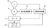
- FIG. 2 is a configuration diagram of a control system according to the first embodiment.
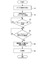
- 5 is a flowchart illustrating an example of an operation of the control system according to the first embodiment.
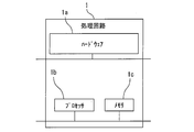
- FIG. 2 is a diagram showing a hardware configuration of a main part of the control system according to the first embodiment.
- 9 is a flowchart illustrating an example of an operation of the control system according to the second embodiment.
- FIG. 1 is a configuration diagram of an elevator to which the control system according to Embodiment 1 is applied.
- the control system 1 is applied to the elevator 2.
- the elevator 2 is provided in a building.
- the building has multiple floors.
- the hoistway passes through each floor of the building.
- the elevator 2 includes a hoist 3, a main rope 4, a car 5, a counterweight 6, and a brake 7.
- the hoisting machine 3 is provided on the hoistway.
- the hoist 3 includes an electric motor 8 and a sheave 9.
- the electric motor 8 is a device that receives power supply and rotates a rotating shaft.
- the power supplied to the motor 8 is, for example, three-phase AC power.
- the control of the motor 8 is performed, for example, by controlling the voltage or frequency of the supplied three-phase AC power.
- the sheave 9 is a device that rotates following the rotation axis of the electric motor 8.
- the main rope 4 is wound around the sheave 9 so as to be able to move following the rotation of the sheave 9.
- the car 5 is provided on the hoistway.
- the car 5 holds one end of the main rope 4 so that the car 5 can move up and down following the movement of the main rope 4 inside the hoistway.
- the counterweight 6 is provided on the hoistway. The counterweight 6 holds the other end of the main rope 4 so that it can move up and down following the movement of the main rope 4 inside the hoistway.
- the brake 7 is a device that brakes the elevation of the car 5 when the car 5 is stopped.
- the brake 7 includes, for example, a brake drum 10, a brake shoe 11, a brake coil 12, an armature 13, a brake arm 14, a spring 15, a displacement sensor 16, and a brake control device 17.
- the brake drum 10 is provided on the rotating shaft of the electric motor 8 so as to be able to rotate in synchronization with the rotating shaft of the electric motor 8.
- the brake drum 10 is, for example, a disk-shaped member.
- the brake shoe 11 faces the outer surface of the brake drum 10.
- the brake coil 12 is a device that generates a magnetic field when energized.
- the armature 13 is a device that is displaced by a magnetic field generated by the brake coil 12.
- the brake arm 14 is connected to the brake shoe 11 so that the brake shoe 11 can contact the outer surface of the brake drum 10.
- the other end of the brake arm 14 contacts the armature 13 so that the displacement of the armature 13 can be transmitted to the brake shoe 11.
- the spring 15 is provided on, for example, the brake arm 14 so that the brake shoe 11 can be pressed against the outer surface of the brake drum 10 by an elastic force.
- the displacement sensor 16 is provided on the armature 13.
- the displacement sensor 16 is a device that detects a displacement of the armature 13.
- the brake control device 17 is a device that controls the operation of the brake 7.
- the control system 1 includes an encoder 18, a brake switch 19, an operation control device 20, and a power conversion device 21.
- the encoder 18 is a device that detects a change in the rotation angle of the rotating shaft of the electric motor 8.
- the encoder 18 is provided on a rotating shaft of the electric motor 8.
- the encoder 18 includes, for example, an element that outputs a pulse signal according to a change in the rotation angle of the rotation shaft of the electric motor 8.
- the brake switch 19 is a device that detects the operation state of the brake 7.
- the operation state of the brake 7 includes braking and releasing the brake 7.
- the brake switch 19 includes, for example, a mechanism that detects an operating state of the brake 7 by detecting a mechanical displacement of a part of the brake 7.
- the displacement detected by the brake switch 19 is, for example, the displacement of the brake arm 14 by the armature 13.
- the brake switch 19 is provided on the brake arm 14, for example.
- the brake switch 19 is in the ON state.
- the brake switch 19 is in the OFF state. By switching from the ON state to the OFF state, the brake switch 19 detects the start of braking of the brake 7.
- the operation control device 20 is connected to the encoder 18 so as to receive a signal indicating a change in the rotation angle of the rotation shaft of the electric motor 8.
- the operation control device 20 is connected to the brake switch 19 so as to receive a signal indicating the operation state of the brake 7.
- the operation control device 20 is connected to the brake 7 so that a control signal can be transmitted.
- the operation control device 20 is connected to the power conversion device 21 so that a control signal can be transmitted.
- the operation control device 20 includes a timer.
- the operation control device 20 stores the delay time To.
- the initial value of the delay time To is set in advance.
- the power converter 21 is connected to an external power supply.
- the power conversion device 21 includes an element or a circuit that converts power supplied from an external power supply into three-phase AC power based on a control signal received from the operation control device 20.
- the power converter 21 is connected to the electric motor 8 so that three-phase AC power can be supplied to the electric motor 8.
- the power conversion device 21 is an example of a power supply device.
- the operation control device 20 In operation of the elevator 2, the operation control device 20 generates a torque command.
- the torque command is a command corresponding to a control target value of the torque generated by the electric motor 8.
- the operation control device 20 transmits a control signal representing the generated torque command to the power conversion device 21.
- the power converter 21 converts power supplied from an external power supply into three-phase AC power based on the received control signal.
- the power converter 21 supplies the converted three-phase AC power to the electric motor 8.
- the electric motor 8 rotates the rotating shaft by receiving the supply of the electric power.
- the sheave 9 rotates following the rotation axis of the electric motor 8.
- the car 5 moves up and down following the movement of the main rope 4 inside the hoistway.
- the counterweight 6 moves up and down following the movement of the main rope 4 inside the hoistway.
- the encoder 18 detects a change in the rotation angle of the rotation shaft of the electric motor 8.
- the encoder 18 outputs a pulse signal corresponding to a change in the rotation angle of the rotating shaft of the electric motor 8 as a signal indicating a change in the rotation angle of the rotating shaft of the electric motor 8.
- the operation control device 20 receives from the encoder 18 a signal indicating a change in the rotation angle of the rotation shaft of the electric motor 8.
- the operation control device 20 acquires information on the rotation speed of the electric motor 8 from the received signal.
- the operation control device 20 generates a torque command such that the rotation speed of the electric motor 8 matches the rotation speed indicated by the speed command.
- the speed command is a command that indicates a rotation speed corresponding to a control target value of the speed at which the car 5 moves up and down.
- the operation control device 20 does not generate a braking command.
- the brake coil 12 When the brake 7 has not received a control signal indicating a braking command from the operation control device 20, the brake coil 12 generates a magnetic field by energization.
- the armature 13 is displaced by a magnetic field generated by the brake coil 12 against the elastic force of the spring 15.
- the displacement of the armature 13 is transmitted from the brake arm 14 to the brake shoe 11.
- the brake shoe 11 is separated from the outer surface of the brake drum 10.
- the operation state of the brake 7 is release.
- the brake switch 19 detects that the brake 7 has been released.
- the brake switch 19 is in the ON state.
- the operation control device 20 transmits a control signal indicating a braking command to the brake 7.
- an unbalanced torque is applied to the sheave 9 of the hoisting machine 3.
- the unbalanced torque is a torque generated by a difference between the weight of the car 5 and the passenger riding the car 5 and the weight of the counterweight 6.
- the electric motor 8 of the hoisting machine 3 holds the rotating shaft without rotating by the torque generated by the electric power supplied from the electric power converter 21.
- the encoder 18 does not output a pulse signal.
- the brake 7 cuts off the power supply to the brake coil 12.
- the brake coil 12 does not generate a magnetic field.
- the brake shoe 11 approaches the outer surface of the brake drum 10 by the elastic force of the spring 15.
- the displacement sensor 16 detects a displacement of the armature 13.
- the displacement sensor 16 transmits a signal indicating the detected displacement to, for example, the brake control device 17.
- the brake control device 17 acquires information on the speed of the armature 13 from the received signal.
- the brake control device 17 generates a magnetic field in the brake coil 12 so as to adjust the speed of the displacement of the armature 13 based on the acquired information on the speed of the armature 13, so that the brake Reduce the speed at which the gap closes.
- the brake shoe 11 contacts the outer surface of the brake drum 10.
- the operation state of the brake 7 is braking.
- the brake switch 19 is turned off.
- the brake switch 19 detects the start of braking of the brake 7.
- the operation control device 20 starts counting the timer when the brake switch 19 is turned off. The timer continues counting until the delay time To stored in the operation control device 20 is reached.
- the brake shoe 11 While the timer continues counting, the brake shoe 11 is pressed against the outer surface of the brake drum 10 by the elastic force of the spring 15. The pressure with which the brake shoe 11 is pressed against the outer surface of the brake drum 10 gradually increases. As the pressure increases, the torque of the brake 7 gradually increases.
- the operation control device 20 transmits a control signal indicating power supply cutoff to the power conversion device 21. Based on the received control signal, power converter 21 cuts off the supply of power to electric motor 8. The electric motor 8 to which the supply of electric power is cut off does not generate torque. The operation control device 20 resets the count of the timer. The operation control device 20 restarts counting of the timer.
- the sheave 9 of the hoist 3 rotates by the unbalanced torque.
- the rotating shaft of the hoist 3 rotates together with the sheave 9.
- the brake drum 10 rotates in synchronization with the rotation shaft while being in contact with the brake shoe 11.
- the encoder 18 detects a change in the rotation angle of the rotation shaft.
- the encoder 18 outputs a pulse signal corresponding to a change in the rotation angle of the rotating shaft of the electric motor 8 as a signal indicating a change in the rotation angle of the rotating shaft of the electric motor 8.
- the operation control device 20 receives from the encoder 18 a signal indicating a change in the rotation angle of the rotation shaft of the electric motor 8.
- the brake shoe 11 is further pressed against the outer surface of the brake drum 10 by the elastic force of the spring 15.
- the pressure at which the brake shoe 11 is pressed against the outer surface of the brake drum 10 further increases.
- the torque of the brake 7 further increases.
- the rotation of the sheave 9 stops.
- the encoder 18 does not output a pulse signal.
- the operation control device 20 acquires the count of the timer when the pulse signal is no longer output from the encoder 18 as the measurement time ⁇ T.
- the operation control device 20 updates the stored delay time To as To + ⁇ T based on the measurement time ⁇ T.
- the operation control device 20 transmits a control signal indicating a braking command to the brake 7.
- the electric motor 8 of the hoisting machine 3 holds the rotating shaft without rotating by the torque generated by the electric power supplied from the electric power converter 21.
- the operation state of the brake 7 becomes braking.
- the brake switch 19 is turned off.
- the brake switch 19 detects the start of braking of the brake 7.
- the operation control device 20 starts counting the timer when the brake switch 19 is turned off. The timer continues counting until the updated delay time To stored in the operation control device 20 is reached.
- FIG. 2 is a configuration diagram of the control system according to the first embodiment.
- FIG. 3 is a flowchart illustrating an example of an operation of the control system according to the first embodiment.
- the operation control device 20 transmits a control signal indicating the generated torque command to the power conversion device 21.
- the power converter 21 converts power supplied from an external power supply into three-phase AC power based on the received control signal.
- the power converter 21 supplies the converted three-phase AC power to the electric motor 8.
- the electric motor 8 receives the supply of electric power and rotates the rotating shaft.
- the encoder 18 detects a change in the rotation angle of the rotation shaft of the electric motor 8.
- the operation control device 20 generates a torque command based on the change in the rotation angle and the speed command detected by the encoder 18.
- the car 5 moves up and down inside the hoistway according to the speed of up and down corresponding to the speed command. Thereafter, the car 5 stops at the landing position.
- step S1 of FIG. 3 the operation control device 20 detects that the car 5 has stopped at the landing position. Thereafter, the operation of the control system 1 proceeds to Step S2.
- step S2 the operation control device 20 transmits a signal indicating a braking command to the brake 7. Thereafter, the operation of the control system 1 proceeds to Step S3.
- step S3 the operation control device 20 determines whether the brake switch 19 is in the ON state. When the result of the determination is Yes, the operation of the control system 1 proceeds to step S3 again. When the determination result is No, the operation control device 20 starts counting the timer. Thereafter, the operation of the control system 1 proceeds to Step S4.
- step S4 the operation control device 20 determines whether the count of the timer has reached the delay time To. When the determination result is No, the operation of the control system 1 proceeds to step S4 again. When the determination result is Yes, the operation control device 20 resets the count of the timer. Thereafter, the operation of the control system 1 proceeds to Step S5.
- step S5 the operation control device 20 transmits a control signal indicating power supply cutoff to the power conversion device 21. After that, the power converter 21 cuts off the supply of power to the electric motor 8. Thereafter, the operation control device 20 restarts counting of the timer. Thereafter, the operation control device 20 acquires the count of the timer when the pulse signal is no longer output from the encoder 18 as the measurement time ⁇ T. Thereafter, the operation of the control system 1 proceeds to Step S6.
- step S6 the operation control device 20 updates the stored delay time To with the measurement time ⁇ T. Thereafter, the operation of the control system 1 ends.
- the control system 1 includes the power conversion device 21, the brake switch 19, and the operation control device 20.
- the power converter 21 supplies electric power to the electric motor 8.
- the electric motor 8 raises and lowers the car 5 of the elevator 2.
- the brake switch 19 detects an operation state of the brake 7.
- the brake 7 brakes the electric motor 8.
- the operation control device 20 causes the power conversion device 21 to cut off the supply of power to the electric motor 8.
- the control system 1 also includes the encoder 18.
- the encoder 18 detects a change in the rotation angle of the rotation shaft of the electric motor 8.
- the operation control device 20 measures a measurement time ⁇ T from when the power conversion device 21 cuts off the power supply to the electric motor 8 until the encoder 18 stops detecting the change in the rotation angle.
- the operation control device 20 updates the delay time To with the measured measurement time ⁇ T.
- the operation control device 20 measures the measurement time ⁇ T from when the delay time To elapses to when the torque of the brake 7 reaches the unbalanced torque.
- the operation control device 20 updates the delay time To with the measurement time ⁇ T.
- the operation control device 20 adjusts the delay time To so as to suppress the rotation of the brake drum 10 in a state where the brake shoe 11 is in contact. Thus, wear of the brake 7 is suppressed.
- the delay time To is adjusted based on the measurement time ⁇ T measured by the output of the encoder 18. Therefore, even when the state of the brake 7 changes due to elapse of time or the like, wear of the brake 7 is suppressed. Since the delay time To is adjusted based on the measurement time ⁇ T, there is no need for tuning by maintenance personnel or the like.
- the brake 7 may be, for example, a disc brake.
- the brake 7 includes, for example, a brake disk and a pair of brake pads.
- the brake disk is provided on the rotating shaft of the electric motor 8 so as to be able to rotate in synchronization with the rotating shaft of the electric motor 8.
- One of the pair of brake pads is provided on one side of the brake disc.
- the other of the pair of brake pads is provided on the other side of the brake disc.
- the brake arm 14 transmits the displacement of the armature 13 to each of the pair of brake pads.
- the brake 7 brakes the electric motor 8 by sandwiching a brake disc between a pair of brake pads.
- the brake 7 may include a displacement sensor that detects a displacement of the brake arm 14 or the brake shoe 11 or the like.
- the brake 7 may include a speed sensor that detects the speed of the armature 13, the brake arm 14, the brake shoe 11, or the like.
- the encoder 18 may directly detect a change in the rotation angle of the rotation shaft of the electric motor 8.
- the encoder 18 may detect a rotation position of a rotation shaft of the electric motor 8.
- the encoder 18 may indirectly detect a change in the rotation angle of the rotation shaft of the electric motor 8 based on the detected rotation position.
- the operation control device 20 does not need to update the delay time To when the encoder 18 does not detect a change in the rotation angle after the power conversion device 21 shuts off the power supply to the electric motor 8.
- FIG. 4 is a diagram illustrating a hardware configuration of a main part of the control system according to the first embodiment.
- Each function of the control system 1 can be realized by a processing circuit.
- the processing circuit includes at least one processor 1b and at least one memory 1c.
- the processing circuit may include at least one dedicated hardware 1a together with or as a substitute for the processor 1b and the memory 1c.
- each function of the control system 1 is realized by software, firmware, or a combination of software and firmware. At least one of software and firmware is described as a program.
- the program is stored in the memory 1c.
- the processor 1b implements each function of the control system 1 by reading and executing a program stored in the memory 1c.
- the processor 1b is also referred to as a CPU (Central Processing Unit), a processing device, an arithmetic device, a microprocessor, a microcomputer, or a DSP.
- the memory 1c includes, for example, a nonvolatile or volatile semiconductor memory such as a RAM, a ROM, a flash memory, an EPROM, and an EEPROM, a magnetic disk, a flexible disk, an optical disk, a compact disk, a mini disk, and a DVD.
- a nonvolatile or volatile semiconductor memory such as a RAM, a ROM, a flash memory, an EPROM, and an EEPROM, a magnetic disk, a flexible disk, an optical disk, a compact disk, a mini disk, and a DVD.
- the processing circuit includes the dedicated hardware 1a
- the processing circuit is realized by, for example, a single circuit, a composite circuit, a programmed processor, a parallel programmed processor, an ASIC, an FPGA, or a combination thereof.
- Each function of the control system 1 can be realized by a processing circuit.
- each function of the control system 1 can be realized by a processing circuit collectively.
- a part of each function of the control system 1 may be realized by dedicated hardware 1a, and the other part may be realized by software or firmware.
- the processing circuit implements each function of the control system 1 by hardware 1a, software, firmware, or a combination thereof.
- the function of the brake control device 17 may be realized by hardware common to the control system 1 or the like.
- Embodiment 2 FIG. In the second embodiment, points different from the example disclosed in the first embodiment will be described in detail. As for features not described in the second embodiment, any of the features disclosed in the first embodiment may be adopted.
- FIG. 5 is a flowchart illustrating an example of an operation of the control system according to the second embodiment.
- control system 1 according to the second embodiment operates in the same manner as the control system 1 according to the first embodiment from step S1 to step S6. After updating the delay time To stored in the operation control device 20 in step S6, the operation of the control system 1 according to the second embodiment proceeds to step S7.
- step S7 the operation control device 20 determines whether the updated delay time To is longer than a predetermined abnormality detection time.
- the operation of the control system 1 proceeds to step S8.
- the result of the determination is No, the operation of the control system 1 ends.
- step S8 the operation control device 20 detects an abnormality of the brake 7. Thereafter, the operation control device 20 disables the use of the elevator 2. Thereafter, the operation of the control system 1 ends.
- the operation control device 20 detects the abnormality of the brake 7.
- the operation control device 20 can detect an abnormality of the brake 7 during operation.
- the operation control device 20 When detecting an abnormality of the brake 7, the operation control device 20 disables the use of the elevator 2.
- the operation control device 20 disables the use of the elevator 2 when an abnormality has occurred in the brake 7.
- the operation of the elevator 2 in a state where the abnormality of the brake 7 has occurred is prevented beforehand.
- the operation control device 20 may report information of the detected abnormality to, for example, a facility or facility that manages information of the elevator 2.
- the operation control device 20 may disable the use of the elevator 2 by, for example, not generating a torque command.
- the operation control device 20 may transmit a control signal indicating an abnormality of the brake 7 to, for example, a device that receives a call from a user. At this time, the device or the like that has received the control signal does not accept the call from the user. As a result, the use of the elevator 2 becomes impossible.
- control system according to the present invention can be applied to an elevator.
- 1 control system 1a hardware, 1b processor, 1c memory, 2 elevator, 3 hoist, 4 main rope, 5 car, 6 balance weight, 7 brake, 8 electric motor, 9 sheave, 10 brake drum, 11 brake shoe , ⁇ 12 ⁇ brake coil, ⁇ 13 ⁇ armature, ⁇ 14 ⁇ brake arm, ⁇ 15 ⁇ spring, ⁇ 16 ⁇ displacement sensor, ⁇ 17 ⁇ brake controller, ⁇ 18 ⁇ encoder, ⁇ 19 ⁇ brake switch, ⁇ 20 ⁇ operation controller, ⁇ 21 ⁇ power converter
Landscapes
- Engineering & Computer Science (AREA)
- Automation & Control Theory (AREA)
- Elevator Control (AREA)
- Braking Arrangements (AREA)
Abstract
本発明の目的は、ブレーキ(7)の磨耗を抑えられる制御システム(1)を提供することである。制御システム(1)は、電力変換装置(21)と、ブレーキスイッチ(19)と、運転制御装置(20)と、を備える。電力変換装置(21)は、電動機(8)に電力を供給する。電動機(8)は、エレベーター(2)のかご(5)を昇降させる。ブレーキスイッチ(19)は、ブレーキ(7)の作動状態を検出する。ブレーキ(7)は、電動機(8)を制動する。ブレーキスイッチ(19)がブレーキ(7)の制動を検出してから遅れ時間Toが経過した後に、運転制御装置(20)は、電力変換装置(21)に電動機(8)への電力の供給を遮断させる。
Description
本発明は、エレベーターの制御システムに関する。
特許文献1にエレベーターの制御システムの例が記載されている。制御システムは、ブレーキを制御する。ブレーキのアーマチュアは、ブレーキシューに連結される。制御システムは、アーマチュアの速度の情報に基づいてブレーキシューとブレーキドラムとの間の間隙が閉じる速度を遅くすることで、ブレーキシューがブレーキドラムに衝突する際に発生する騒音を抑制する。
しかしながら、特許文献1に記載の制御システムによって、ブレーキのトルクは徐々に大きくなる。このため、エレベーターの巻上機の電動機に供給される電力は、ブレーキのトルクが大きくなる前に遮断されることがある。このとき、ブレーキシューとブレーキドラムが接触した状態で、ブレーキドラムが回転することがある。この場合、ブレーキが磨耗する。
本発明は、このような課題を解決するためになされた。本発明の目的は、ブレーキの磨耗を抑えられる制御システムを提供することである。
本発明に係るエレベーターの制御システムは、エレベーターのかごを昇降させる電動機に電力を供給する電力供給装置と、電動機を制動するブレーキの作動状態を検出するブレーキスイッチと、ブレーキスイッチがブレーキの制動を検出してから待機時間が経過した後に電力供給装置から電動機への電力の供給を遮断する運転制御装置と、を備える。
本発明によれば、エレベーターの制御システムは、電力供給装置と、電力供給装置は、エレベーターのかごを昇降させる電動機に電力を供給する。ブレーキスイッチは、電動機を制動するブレーキの作動状態を検出する。運転制御装置は、ブレーキスイッチがブレーキの制動を検出してから待機時間が経過した後に電力供給装置から電動機への電力の供給を遮断する。これにより、ブレーキの磨耗が抑えられる。
本発明を実施するための形態について添付の図面を参照しながら説明する。各図において、同一または相当する部分には同一の符号を付して、重複する説明は適宜に簡略化または省略する。
実施の形態1.
図1は、実施の形態1に係る制御システムが適用されるエレベーターの構成図である。
図1は、実施の形態1に係る制御システムが適用されるエレベーターの構成図である。
制御システム1は、エレベーター2に適用される。エレベーター2は、建築物に設けられる。建築物は、複数の階を有する。エレベーター2において、昇降路は、建築物の各階を貫く。エレベーター2は、巻上機3と、主ロープ4と、かご5と、釣合重り6と、ブレーキ7と、を備える。
巻上機3は、昇降路に設けられる。巻上機3は、電動機8と、シーブ9と、を備える。電動機8は、電力の供給を受けて回転軸を回転させる機器である。電動機8に供給される電力は、例えば三相交流電力である。電動機8の制御は、例えば供給される三相交流電力の電圧または周波数などの制御によって行われる。シーブ9は、電動機8の回転軸に追従して回転する機器である。
主ロープ4は、シーブ9の回転に追従して移動しうるように、シーブ9に巻きかけられる。
かご5は、昇降路に設けられる。かご5は、昇降路の内部において主ロープ4の移動に追従して昇降しうるように、主ロープ4の一端を保持する。釣合重り6は、昇降路に設けられる。釣合重り6は、昇降路の内部において主ロープ4の移動に追従して昇降しうるように、主ロープ4の他端を保持する。
ブレーキ7は、かご5が停止しているときなどにかご5の昇降を制動する装置である。ブレーキ7は、例えば、ブレーキドラム10と、ブレーキシュー11と、ブレーキコイル12と、アーマチュア13と、ブレーキアーム14と、バネ15と、変位センサー16と、ブレーキ制御装置17と、を備える。ブレーキドラム10は、電動機8の回転軸と同期して回転しうるように、電動機8の回転軸に設けられる。ブレーキドラム10は、例えば円盤状の部材である。ブレーキシュー11は、ブレーキドラム10の外面に対向する。ブレーキコイル12は、通電によって磁界を発生させる機器である。アーマチュア13は、ブレーキコイル12が発生させる磁界によって変位する機器である。ブレーキアーム14の一端は、ブレーキシュー11をブレーキドラム10の外面に接触させうるように、ブレーキシュー11に連結される。ブレーキアーム14の他端は、アーマチュア13の変位をブレーキシュー11に伝達しうるように、アーマチュア13に接触する。バネ15は、弾性力によりブレーキシュー11をブレーキドラム10の外面に押し付けうるように、例えばブレーキアーム14に設けられる。変位センサー16は、アーマチュア13に設けられる。変位センサー16は、アーマチュア13の変位を検出する機器である。ブレーキ制御装置17は、ブレーキ7の動作を制御する装置である。
制御システム1は、エンコーダー18と、ブレーキスイッチ19と、運転制御装置20と、電力変換装置21と、を備える。
エンコーダー18は、電動機8の回転軸の回転角の変化を検出する装置である。エンコーダー18は、電動機8の回転軸に設けられる。エンコーダー18は、例えば電動機8の回転軸の回転角の変化に応じてパルス信号を出力する素子を搭載する。
ブレーキスイッチ19は、ブレーキ7の作動状態を検出する装置である。ブレーキ7の作動状態は、ブレーキ7の制動および解放を含む。ブレーキスイッチ19は、例えばブレーキ7の一部の機械的な変位を検出することによってブレーキ7の作動状態を検出する機構を備える。ブレーキスイッチ19が検出する変位は、例えば、アーマチュア13によるブレーキアーム14の変位である。ブレーキスイッチ19は、例えばブレーキアーム14に設けられる。ブレーキ7の解放を検出しているとき、ブレーキスイッチ19は、ON状態である。ブレーキ7の制動を検出しているとき、ブレーキスイッチ19は、OFF状態である。ON状態からOFF状態への切り替わりによって、ブレーキスイッチ19は、ブレーキ7の制動の開始を検出する。
運転制御装置20は、電動機8の回転軸の回転角の変化を表す信号を受信しうるように、エンコーダー18に接続される。運転制御装置20は、ブレーキ7の作動状態を表す信号を受信しうるように、ブレーキスイッチ19に接続される。運転制御装置20は、制御信号を送信しうるように、ブレーキ7に接続される。運転制御装置20は、制御信号を送信しうるように、電力変換装置21に接続される。運転制御装置20は、タイマーを備える。運転制御装置20は、遅れ時間Toを記憶する。遅れ時間Toの初期値は、予め設定される。
電力変換装置21は、外部の電源に接続される。電力変換装置21は、外部の電源から供給される電力を運転制御装置20から受信する制御信号に基づいて三相交流電力に変換する素子または回路などを搭載する。電力変換装置21は、三相交流電力を電動機8に供給しうるように、電動機8に接続される。電力変換装置21は、電力供給装置の例である。
引き続き図1を用いて、制御システム1の機能を説明する。
エレベーター2の運転において、運転制御装置20は、トルク指令を生成する。トルク指令は、電動機8が発生させるトルクの制御目標値に対応する指令である。運転制御装置20は、生成したトルク指令を表す制御信号を電力変換装置21に送信する。
電力変換装置21は、受信した制御信号に基づいて、外部の電源から供給される電力を三相交流電力に変換する。電力変換装置21は、変換した三相交流電力を電動機8に供給する。
電動機8は、電力の供給を受けて回転軸を回転させる。シーブ9は、電動機8の回転軸に追従して回転する。かご5は、昇降路の内部において主ロープ4の移動に追従して昇降する。釣合重り6は、昇降路の内部において主ロープ4の移動に追従して昇降する。
エンコーダー18は、電動機8の回転軸の回転角の変化を検出する。エンコーダー18は、電動機8の回転軸の回転角の変化に応じたパルス信号を、電動機8の回転軸の回転角の変化を表す信号として出力する。
運転制御装置20は、エンコーダー18から、電動機8の回転軸の回転角の変化を表す信号を受信する。運転制御装置20は、受信した信号から、電動機8の回転速度の情報を取得する。運転制御装置20は、速度指令が表す回転速度に電動機8の回転速度が一致するようにトルク指令を生成する。速度指令は、かご5の昇降の速度の制御目標値に対応する回転速度を表す指令である。
このとき、運転制御装置20は、制動指令を生成しない。ブレーキ7が運転制御装置20から制動指令を表す制御信号を受信していないときに、ブレーキコイル12は、通電によって磁界を発生させる。アーマチュア13は、バネ15の弾性力に抗して、ブレーキコイル12が発生させる磁界によって変位している。ブレーキシュー11は、ブレーキアーム14からアーマチュア13の変位が伝達されている。ブレーキシュー11は、ブレーキドラム10の外面から離れている。ブレーキ7の作動状態は、解放である。ブレーキスイッチ19は、ブレーキ7の解放を検出している。ブレーキスイッチ19は、ON状態である。
かご5が着床位置に停止しているときに、運転制御装置20は制動指令を表す制御信号をブレーキ7に送信する。このとき、巻上機3のシーブ9に不平衡トルクがかかる。不平衡トルクは、かご5およびかご5に乗っている乗客の重量と釣合重り6の重量との差により生じるトルクである。ここで、巻上機3の電動機8は、電力変換装置21から供給される電力により発生させるトルクによって、回転軸を回転させずに保持している。電動機8の回転軸が回転していないときに、エンコーダー18は、パルス信号を出力しない。
受信した制御信号に基づいて、ブレーキ7は、ブレーキコイル12の通電を遮断する。ブレーキコイル12は、磁界を発生させない。バネ15の弾性力によって、ブレーキシュー11は、ブレーキドラム10の外面に近づく。変位センサー16は、アーマチュア13の変位を検出する。変位センサー16は、検出した変位を表す信号を例えばブレーキ制御装置17に送信する。ブレーキ制御装置17は、受信した信号からアーマチュア13の速度の情報を取得する。ブレーキ制御装置17は、取得したアーマチュア13の速度の情報に基づいてアーマチュア13の変位の速度を調整するようにブレーキコイル12に磁界を発生させることで、ブレーキシュー11とブレーキドラム10との間の間隙が閉じる速度を遅くする。ブレーキシュー11は、ブレーキドラム10の外面に接触する。ブレーキ7の作動状態は、制動になる。ブレーキスイッチ19は、OFF状態になる。ブレーキスイッチ19は、ブレーキ7の制動の開始を検出する。
運転制御装置20は、ブレーキスイッチ19がOFF状態になったときに、タイマーのカウントをスタートさせる。タイマーは、運転制御装置20が記憶している遅れ時間Toに達するまで、カウントを継続する。
タイマーがカウントを継続している間に、ブレーキシュー11は、バネ15の弾性力によりブレーキドラム10の外面に押し付けられる。ブレーキシュー11がブレーキドラム10の外面に押し付けられる圧力は、徐々に大きくなる。当該圧力が大きくなるにつれて、ブレーキ7のトルクは、徐々に大きくなる。
タイマーのカウントが遅れ時間Toに達したときに、運転制御装置20は、電力供給の遮断を表す制御信号を電力変換装置21に送信する。受信した制御信号に基づいて、電力変換装置21は、電動機8への電力の供給を遮断する。電力の供給が遮断された電動機8は、トルクを発生させない。運転制御装置20は、タイマーのカウントをリセットする。運転制御装置20は、タイマーのカウントを再びスタートさせる。
ブレーキ7のトルクが不平衡トルクより小さいときに電動機8への電力の供給が遮断された場合に、巻上機3のシーブ9は不平衡トルクによって回転する。巻上機3の回転軸は、シーブ9とともに回転する。ブレーキドラム10は、ブレーキシュー11と接触している状態で、回転軸と同期して回転する。エンコーダー18は、回転軸の回転角の変化を検出する。エンコーダー18は、電動機8の回転軸の回転角の変化に応じたパルス信号を、電動機8の回転軸の回転角の変化を表す信号として出力する。運転制御装置20は、エンコーダー18から、電動機8の回転軸の回転角の変化を表す信号を受信する。
ブレーキシュー11は、バネ15の弾性力によりブレーキドラム10の外面にさらに押し付けられる。ブレーキシュー11がブレーキドラム10の外面に押し付けられる圧力は、さらに大きくなる。当該圧力が大きくなるにつれて、ブレーキ7のトルクは、さらに大きくなる。ブレーキ7のトルクが不平衡トルクに達したときに、シーブ9の回転は停止する。このとき、エンコーダー18は、パルス信号を出力しない。運転制御装置20は、エンコーダー18からパルス信号が出力されなくなったときのタイマーのカウントを、測定時間ΔTとして取得する。
運転制御装置20は、測定時間ΔTによって、記憶している遅れ時間ToをTo+ΔTとして更新する。
その後、運転制御指令が生成するトルク指令に基づいて、かご5は、昇降路の内部において昇降する。
その後、運転制御装置20は、かご5が着床位置に再び停止しているときに、運転制御装置20は制動指令を表す制御信号をブレーキ7に送信する。巻上機3の電動機8は、電力変換装置21から供給される電力により発生させるトルクによって回転軸を回転させずに保持している。受信した制御信号に基づいて、ブレーキ7の作動状態は、制動になる。ブレーキスイッチ19は、OFF状態になる。ブレーキスイッチ19は、ブレーキ7の制動の開始を検出する。
運転制御装置20は、ブレーキスイッチ19がOFF状態になったときに、タイマーのカウントをスタートさせる。タイマーは、運転制御装置20が記憶している更新された遅れ時間Toに達するまで、カウントを継続する。
ブレーキ7の最大のトルクが不平衡トルクより大きいときに電動機8への電力の供給が遮断された場合に、巻上機3のシーブ9は不平衡トルクによって回転しない。
続いて、図2および図3を用いて、制御システム1の動作を説明する。
図2は、実施の形態1に係る制御システムの構成図である。図3は、実施の形態1に係る制御システムの動作の例を示すフローチャートである。
図2は、実施の形態1に係る制御システムの構成図である。図3は、実施の形態1に係る制御システムの動作の例を示すフローチャートである。
図2において、運転制御装置20は、生成したトルク指令を表す制御信号を電力変換装置21に送信する。電力変換装置21は、受信した制御信号に基づいて、外部の電源から供給される電力を三相交流電力に変換する。電力変換装置21は、変換した三相交流電力を電動機8に供給する。電動機8は、電力の供給を受けて回転軸を回転させる。エンコーダー18は、電動機8の回転軸の回転角の変化を検出する。運転制御装置20は、エンコーダー18が検出した回転角の変化および速度指令に基づいて、トルク指令を生成する。かご5は、速度指令が対応する昇降の速度によって、昇降路の内部を昇降する。その後、かご5は、着床位置に停止する。
図3のステップS1において、運転制御装置20は、かご5が着床位置に停止していることを検出する。その後、制御システム1の動作は、ステップS2に進む。
ステップS2において、運転制御装置20は、制動指令を表す信号をブレーキ7に送信する。その後、制御システム1の動作は、ステップS3に進む。
ステップS3において、運転制御装置20は、ブレーキスイッチ19がON状態であるかを判定する。判定結果がYesのときに、制御システム1の動作は、再びステップS3に進む。判定結果がNoのときに、運転制御装置20は、タイマーのカウントをスタートさせる。その後、制御システム1の動作は、ステップS4に進む。
ステップS4において、運転制御装置20は、タイマーのカウントが遅れ時間Toに達したかを判定する。判定結果がNoのときに、制御システム1の動作は、再びステップS4に進む。判定結果がYesのときに、運転制御装置20は、タイマーのカウントをリセットする。その後、制御システム1の動作は、ステップS5に進む。
ステップS5において、運転制御装置20は、電力供給の遮断を表す制御信号を電力変換装置21に送信する。その後、電力変換装置21は、電動機8への電力の供給を遮断する。その後、運転制御装置20は、タイマーのカウントを再びスタートさせる。その後、運転制御装置20は、エンコーダー18からパルス信号が出力されなくなったときのタイマーのカウントを、測定時間ΔTとして取得する。その後、制御システム1の動作は、ステップS6に進む。
ステップS6において、運転制御装置20は、測定時間ΔTによって、記憶している遅れ時間Toを更新する。その後、制御システム1の動作は、終了する。
以上に説明したように、実施の形態1に係る制御システム1は、電力変換装置21と、ブレーキスイッチ19と、運転制御装置20と、を備える。電力変換装置21は、電動機8に電力を供給する。電動機8は、エレベーター2のかご5を昇降させる。ブレーキスイッチ19は、ブレーキ7の作動状態を検出する。ブレーキ7は、電動機8を制動する。ブレーキスイッチ19がブレーキ7の制動を検出してから遅れ時間Toが経過した後に、運転制御装置20は、電力変換装置21に電動機8への電力の供給を遮断させる。
ブレーキスイッチ19が制動を検出してからトルクが徐々に大きくなるブレーキ7においても、電動機8に供給される電力は、遅れ時間Toの経過によってブレーキ7のトルクが大きくなってから遮断される。このため、ブレーキシュー11とブレーキドラム10とが接触した状態におけるブレーキドラム10の回転が抑えられる。これにより、ブレーキ7の磨耗が抑えられる。
巻上機3およびブレーキ7が昇降路の内部に設けられる場合に、ブレーキ7が小型であれば昇降路内における配置の自由度が高まる。ブレーキ7を小型にする場合に、例えばアーマチュア13を変位させるバネ15の弾性力を強くすることによって、ブレーキ7のトルクが確保される。このとき、ブレーキ7の制御装置は、アーマチュア13の速度の情報に基づいてブレーキシュー11とブレーキドラム10との間の間隙が閉じる速度を遅くする。これにより、バネ15の弾性力によってブレーキシュー11がブレーキドラム10に衝突して発生させる騒音が抑制される。このため、かご5の内部に乗客がいる場合にも、騒音によって乗客に不快感を与えることが抑えられる。このブレーキ7において、ブレーキスイッチ19が制動を検出してからブレーキ7のトルクは徐々に大きくなる。この場合においても、制御システム1は、ブレーキ7の制動によって発生する騒音の抑制と、ブレーキ7の磨耗の抑制と、を両立できる。
また、制御システム1は、エンコーダー18を備える。エンコーダー18は、電動機8の回転軸の回転角の変化を検出する。運転制御装置20は、電力変換装置21に電動機8への電力の供給を遮断させてからエンコーダー18が回転角の変化を検出しなくなるまでの測定時間ΔTを測定する。運転制御装置20は、測定した測定時間ΔTによって遅れ時間Toを更新する。
遅れ時間Toが短い場合に、ブレーキ7のトルクが不平衡トルクより小さいうちに電動機8への電力の供給が遮断されることがある。この場合に、運転制御装置20は、遅れ時間Toが経過してからブレーキ7のトルクが不平衡トルクに達するまでの測定時間ΔTを測定する。運転制御装置20は、測定時間ΔTによって遅れ時間Toを更新する。これにより、再びブレーキ7が電動機8を制動するときに、より長い遅れ時間Toが経過した後に電動機8への電力の供給が遮断される。このため、電動機8への電力の供給が遮断されたときのブレーキ7のトルクはより大きくなる。これにより、巻上機3のシーブ9が不平衡トルクによって回転することが抑制される。このように、運転制御装置20は、ブレーキシュー11が接触した状態のブレーキドラム10の回転を抑えるように遅れ時間Toを調整する。これにより、ブレーキ7の磨耗が抑えられる。
時間の経過などによってブレーキ7の状態が変化するときに、トルクが大きくなる時間などが変化することがある。時間の経過などによってブレーキ7の状態が変化する場合においても、遅れ時間Toは、エンコーダー18の出力によって測定された測定時間ΔTに基づいて調整される。このため、時間の経過などによってブレーキ7の状態が変化する場合においても、ブレーキ7の磨耗が抑えられる。遅れ時間Toは、測定時間ΔTに基づいて調整されるので、保守員などによるチューニングを必要としない。
なお、ブレーキ7は例えばディスクブレーキであってもよい。このとき、ブレーキ7は、例えば、ブレーキディスクと、一対のブレーキパッドと、を備える。ブレーキディスクは、電動機8の回転軸と同期して回転しうるように、電動機8の回転軸に設けられる。一対のブレーキパッドの一方は、ブレーキディスクの一側に設けられる。一対のブレーキパッドの他方は、ブレーキディスクの他側に設けられる。ブレーキアーム14は、アーマチュア13の変位を一対のブレーキパッドの各々に伝達する。ブレーキ7は、一対のブレーキパッドでブレーキディスクを挟み込むことによって、電動機8を制動する。
ブレーキ7は、ブレーキアーム14またはブレーキシュー11などの変位を検出する変位センサーを備えてもよい。ブレーキ7は、アーマチュア13、ブレーキアーム14またはブレーキシュー11などの速度を検出する速度センサーを備えてもよい。
エンコーダー18は、電動機8の回転軸の回転角の変化を直接検出してもよい。エンコーダー18は、電動機8の回転軸の回転位置を検出してもよい。エンコーダー18は、検出した回転位置に基づいて、電動機8の回転軸の回転角の変化を間接的に検出してもよい。
運転制御装置20は、電力変換装置21に電動機8への電力の供給を遮断させてからエンコーダー18が回転角の変化を検出しない場合に、遅れ時間Toを更新しなくてもよい。
続いて、図4を用いて制御システム1のハードウェア構成の例について説明する。
図4は、実施の形態1に係る制御システムの主要部のハードウェア構成を示す図である。
図4は、実施の形態1に係る制御システムの主要部のハードウェア構成を示す図である。
制御システム1の各機能は、処理回路により実現し得る。処理回路は、少なくとも1つのプロセッサ1bと少なくとも1つのメモリ1cとを備える。処理回路は、プロセッサ1bおよびメモリ1cと共に、あるいはそれらの代用として、少なくとも1つの専用のハードウェア1aを備えてもよい。
処理回路がプロセッサ1bとメモリ1cとを備える場合、制御システム1の各機能は、ソフトウェア、ファームウェア、またはソフトウェアとファームウェアとの組み合わせで実現される。ソフトウェアおよびファームウェアの少なくとも一方は、プログラムとして記述される。そのプログラムはメモリ1cに格納される。プロセッサ1bは、メモリ1cに記憶されたプログラムを読み出して実行することにより、制御システム1の各機能を実現する。
プロセッサ1bは、CPU(Central Processing Unit)、処理装置、演算装置、マイクロプロセッサ、マイクロコンピュータ、DSPともいう。メモリ1cは、例えば、RAM、ROM、フラッシュメモリ、EPROM、EEPROM等の、不揮発性または揮発性の半導体メモリ、磁気ディスク、フレキシブルディスク、光ディスク、コンパクトディスク、ミニディスク、DVD等により構成される。
処理回路が専用のハードウェア1aを備える場合、処理回路は、例えば、単一回路、複合回路、プログラム化したプロセッサ、並列プログラム化したプロセッサ、ASIC、FPGA、またはこれらの組み合わせで実現される。
制御システム1の各機能は、それぞれ処理回路で実現することができる。あるいは、制御システム1の各機能は、まとめて処理回路で実現することもできる。制御システム1の各機能について、一部を専用のハードウェア1aで実現し、他部をソフトウェアまたはファームウェアで実現してもよい。このように、処理回路は、ハードウェア1a、ソフトウェア、ファームウェア、またはこれらの組み合わせで制御システム1の各機能を実現する。
ブレーキ制御装置17の機能は、制御システム1と共通のハードウェアなどによって実現されてもよい。
実施の形態2.
実施の形態2では、実施の形態1で開示された例と相違する点について詳しく説明する。実施の形態2で説明しない特徴については、実施の形態1で開示された例のいずれの特徴が採用されてもよい。
実施の形態2では、実施の形態1で開示された例と相違する点について詳しく説明する。実施の形態2で説明しない特徴については、実施の形態1で開示された例のいずれの特徴が採用されてもよい。
図5を用いて、実施の形態2に係る制御システム1の動作を説明する。
図5は、実施の形態2に係る制御システムの動作の例を示すフローチャートである。
図5は、実施の形態2に係る制御システムの動作の例を示すフローチャートである。
実施の形態2に係る制御システム1は、ステップS1からステップS6までにおいて、実施の形態1に係る制御システム1と同様に動作する。ステップS6において運転制御装置20が記憶している遅れ時間Toを更新した後、実施の形態2に係る制御システム1の動作は、ステップS7に進む。
ステップS7において、運転制御装置20は、更新された遅れ時間Toが予め定められた異常検出時間より長いかを判定する。判定結果がYesのときに、制御システム1の動作は、ステップS8に進む。判定結果がNoのときに、制御システム1の動作は、終了する。
ステップS8において、運転制御装置20は、ブレーキ7の異常を検出する。その後、運転制御装置20は、エレベーター2の使用を不可にする。その後、制御システム1の動作は、終了する。
以上に説明したように、実施の形態2に係る制御システム1において、遅れ時間Toが予め定められた異常検出時間より長い場合に、運転制御装置20は、ブレーキ7の異常を検出する。
異常検出時間の間にブレーキ7のトルクの大きさが不平衡トルクの大きさに達しない場合に、遅れ時間Toが予め定められた異常検出時間より長くなる。このため、遅れ時間Toが予め定められた異常検出時間より長い状態は、ブレーキ7の故障などの異常を表す。このため、運転制御装置20は、運転においてブレーキ7の異常を検出できる。
また、ブレーキ7の異常を検出する場合に、運転制御装置20は、エレベーター2の使用を不可にする。
運転制御装置20は、ブレーキ7に異常が発生している場合に、エレベーター2の使用を不可にする。これにより、ブレーキ7の異常が発生している状態でのエレベーター2の運転が未然に防がれる。
なお、ブレーキ7の異常を検出する場合に、運転制御装置20は、例えばエレベーター2の情報を管理する設備または施設などに検出した異常の情報を通報してもよい。
運転制御装置20は、例えばトルク指令を生成しないことなどによってエレベーター2の使用を不可にしてもよい。運転制御装置20は、例えば利用者の呼びを受け付ける装置などに、ブレーキ7の異常を表す制御信号を送信してもよい。このとき、制御信号を受信した装置などは、利用者の呼びを受け付けない。これにより、エレベーター2の使用が不可になる。
本発明に係る制御システムは、エレベーターに適用できる。
1 制御システム、 1a ハードウェア、 1b プロセッサ、 1c メモリ、 2 エレベーター、 3 巻上機、 4 主ロープ、 5 かご、 6 釣合重り、 7 ブレーキ、 8 電動機、 9 シーブ、 10 ブレーキドラム、 11 ブレーキシュー、 12 ブレーキコイル、 13 アーマチュア、 14 ブレーキアーム、 15 バネ、 16 変位センサー、 17 ブレーキ制御装置、 18 エンコーダー、 19 ブレーキスイッチ、 20 運転制御装置、 21 電力変換装置
Claims (4)
- エレベーターのかごを昇降させる電動機に電力を供給する電力供給装置と、
前記電動機を制動するブレーキの作動状態を検出するブレーキスイッチと、
前記ブレーキスイッチが前記ブレーキの制動を検出してから遅れ時間が経過した後に前記電力供給装置に前記電動機への電力の供給を遮断させる運転制御装置と、
を備えるエレベーターの制御システム。 - 前記電動機の回転軸の回転角の変化を検出するエンコーダー
を備え、
前記運転制御装置は、前記電力供給装置に前記電動機への電力の供給を遮断させてから前記エンコーダーが前記回転角の変化を検出しなくなるまでの時間を測定し、測定した当該時間によって前記遅れ時間を更新する請求項1に記載のエレベーターの制御システム。 - 前記運転制御装置は、前記遅れ時間が予め定められた時間より長い場合に前記ブレーキの異常を検出する請求項2に記載のエレベーターの制御システム。
- 前記運転制御装置は、前記ブレーキの異常を検出する場合にエレベーターの使用を不可にする請求項3に記載のエレベーターの制御システム。
Priority Applications (3)
| Application Number | Priority Date | Filing Date | Title |
|---|---|---|---|
| CN201880093575.9A CN112292341B (zh) | 2018-06-25 | 2018-06-25 | 电梯的控制系统 |
| JP2020526736A JP6912006B2 (ja) | 2018-06-25 | 2018-06-25 | エレベーターの制御システム |
| PCT/JP2018/024047 WO2020003356A1 (ja) | 2018-06-25 | 2018-06-25 | エレベーターの制御システム |
Applications Claiming Priority (1)
| Application Number | Priority Date | Filing Date | Title |
|---|---|---|---|
| PCT/JP2018/024047 WO2020003356A1 (ja) | 2018-06-25 | 2018-06-25 | エレベーターの制御システム |
Publications (1)
| Publication Number | Publication Date |
|---|---|
| WO2020003356A1 true WO2020003356A1 (ja) | 2020-01-02 |
Family
ID=68984731
Family Applications (1)
| Application Number | Title | Priority Date | Filing Date |
|---|---|---|---|
| PCT/JP2018/024047 Ceased WO2020003356A1 (ja) | 2018-06-25 | 2018-06-25 | エレベーターの制御システム |
Country Status (3)
| Country | Link |
|---|---|
| JP (1) | JP6912006B2 (ja) |
| CN (1) | CN112292341B (ja) |
| WO (1) | WO2020003356A1 (ja) |
Cited By (1)
| Publication number | Priority date | Publication date | Assignee | Title |
|---|---|---|---|---|
| US12559343B2 (en) | 2020-12-04 | 2026-02-24 | Otis Elevator Company | Emergency terminal deceleration in elevator systems |
Citations (3)
| Publication number | Priority date | Publication date | Assignee | Title |
|---|---|---|---|---|
| JP2006096510A (ja) * | 2004-09-29 | 2006-04-13 | Mitsubishi Electric Corp | エレベータ装置 |
| JP2013124179A (ja) * | 2011-12-16 | 2013-06-24 | Hitachi Ltd | エレベータシステム及びエレベータの制御方法 |
| JP2017214223A (ja) * | 2012-05-31 | 2017-12-07 | コネ コーポレイションKone Corporation | ブレーキコントローラおよびエレベータシステム |
Family Cites Families (7)
| Publication number | Priority date | Publication date | Assignee | Title |
|---|---|---|---|---|
| GB1309134A (en) * | 1969-06-30 | 1973-03-07 | Westinghouse Electric Corp | Electric motor control system |
| JPH0930750A (ja) * | 1995-07-14 | 1997-02-04 | Hitachi Building Syst Co Ltd | エレベーターのブレーキ特性評価装置 |
| WO2010095243A1 (ja) * | 2009-02-20 | 2010-08-26 | 三菱電機株式会社 | エレベータのブレーキ装置 |
| JP2012025526A (ja) * | 2010-07-22 | 2012-02-09 | Toshiba Elevator Co Ltd | エレベータのブレーキ異常検出システムおよび方法 |
| JP5932577B2 (ja) * | 2012-09-06 | 2016-06-08 | 株式会社日立製作所 | エレベータの安全システム |
| CN103407850B (zh) * | 2013-07-31 | 2015-05-06 | 日立电梯(中国)有限公司 | 电梯智能制动控制方法与装置 |
| JP6449806B2 (ja) * | 2016-03-30 | 2019-01-09 | 株式会社日立製作所 | エレベータ装置及びその動作制御方法 |
-
2018
- 2018-06-25 JP JP2020526736A patent/JP6912006B2/ja active Active
- 2018-06-25 WO PCT/JP2018/024047 patent/WO2020003356A1/ja not_active Ceased
- 2018-06-25 CN CN201880093575.9A patent/CN112292341B/zh active Active
Patent Citations (3)
| Publication number | Priority date | Publication date | Assignee | Title |
|---|---|---|---|---|
| JP2006096510A (ja) * | 2004-09-29 | 2006-04-13 | Mitsubishi Electric Corp | エレベータ装置 |
| JP2013124179A (ja) * | 2011-12-16 | 2013-06-24 | Hitachi Ltd | エレベータシステム及びエレベータの制御方法 |
| JP2017214223A (ja) * | 2012-05-31 | 2017-12-07 | コネ コーポレイションKone Corporation | ブレーキコントローラおよびエレベータシステム |
Cited By (1)
| Publication number | Priority date | Publication date | Assignee | Title |
|---|---|---|---|---|
| US12559343B2 (en) | 2020-12-04 | 2026-02-24 | Otis Elevator Company | Emergency terminal deceleration in elevator systems |
Also Published As
| Publication number | Publication date |
|---|---|
| JPWO2020003356A1 (ja) | 2021-02-15 |
| JP6912006B2 (ja) | 2021-07-28 |
| CN112292341B (zh) | 2022-05-31 |
| CN112292341A (zh) | 2021-01-29 |
Similar Documents
| Publication | Publication Date | Title |
|---|---|---|
| JP5474040B2 (ja) | エレベータのブレーキ装置 | |
| CN105283404B (zh) | 用于人员运送设备的制动方法、用于执行制动方法的制动控制装置以及具有制动控制装置的人员运送设备 | |
| JP5079517B2 (ja) | エレベーターの非常停止システム | |
| KR100973881B1 (ko) | 엘리베이터 장치 | |
| JP5053075B2 (ja) | エレベータ装置 | |
| JP5138361B2 (ja) | エレベータ装置 | |
| JPWO2008117423A1 (ja) | エレベータのブレーキ装置 | |
| EP2321211B1 (en) | Elevator system, and method in conjunction with an elevator system | |
| CN108698790B (zh) | 电梯以及救援运转控制方法 | |
| JP2014169186A (ja) | トラクションシーブエレベータおよびトラクションシーブの駆動方法 | |
| JPH07206288A (ja) | エレベーター | |
| JP2011143982A (ja) | エレベータの制動制御装置及び制動制御方法 | |
| JP5031767B2 (ja) | エレベータ装置 | |
| JP6912006B2 (ja) | エレベーターの制御システム | |
| KR101250735B1 (ko) | 엘리베이터 장치 | |
| JP6655489B2 (ja) | エレベーター | |
| JP6449806B2 (ja) | エレベータ装置及びその動作制御方法 | |
| JP6821086B2 (ja) | エレベーター制御装置およびエレベーター制御方法 | |
| JP5774166B2 (ja) | エレベータ装置 | |
| US20240059522A1 (en) | Elevator system | |
| JP2007084174A (ja) | エレベーターのブレーキ装置 | |
| HK40046326A (en) | A method for monitoring brake dragging of an elevator | |
| JP2019001649A (ja) | エレベータ装置及びその制御方法 | |
| HK1214578B (en) | Braking method for a passenger transport system, brake control for carrying out the braking method and passenger transport system having a brake control |
Legal Events
| Date | Code | Title | Description |
|---|---|---|---|
| 121 | Ep: the epo has been informed by wipo that ep was designated in this application |
Ref document number: 18923776 Country of ref document: EP Kind code of ref document: A1 |
|
| ENP | Entry into the national phase |
Ref document number: 2020526736 Country of ref document: JP Kind code of ref document: A |
|
| NENP | Non-entry into the national phase |
Ref country code: DE |
|
| 122 | Ep: pct application non-entry in european phase |
Ref document number: 18923776 Country of ref document: EP Kind code of ref document: A1 |