WO2019244641A1 - 電源装置 - Google Patents
電源装置 Download PDFInfo
- Publication number
- WO2019244641A1 WO2019244641A1 PCT/JP2019/022438 JP2019022438W WO2019244641A1 WO 2019244641 A1 WO2019244641 A1 WO 2019244641A1 JP 2019022438 W JP2019022438 W JP 2019022438W WO 2019244641 A1 WO2019244641 A1 WO 2019244641A1
- Authority
- WO
- WIPO (PCT)
- Prior art keywords
- secondary battery
- power supply
- battery
- supply device
- battery cell
- Prior art date
- Legal status (The legal status is an assumption and is not a legal conclusion. Google has not performed a legal analysis and makes no representation as to the accuracy of the status listed.)
- Ceased
Links
Images



Classifications
-
- H—ELECTRICITY
- H01—ELECTRIC ELEMENTS
- H01M—PROCESSES OR MEANS, e.g. BATTERIES, FOR THE DIRECT CONVERSION OF CHEMICAL ENERGY INTO ELECTRICAL ENERGY
- H01M50/00—Constructional details or processes of manufacture of the non-active parts of electrochemical cells other than fuel cells, e.g. hybrid cells
- H01M50/20—Mountings; Secondary casings or frames; Racks, modules or packs; Suspension devices; Shock absorbers; Transport or carrying devices; Holders
- H01M50/204—Racks, modules or packs for multiple batteries or multiple cells
- H01M50/207—Racks, modules or packs for multiple batteries or multiple cells characterised by their shape
- H01M50/213—Racks, modules or packs for multiple batteries or multiple cells characterised by their shape adapted for cells having curved cross-section, e.g. round or elliptic
-
- H—ELECTRICITY
- H01—ELECTRIC ELEMENTS
- H01M—PROCESSES OR MEANS, e.g. BATTERIES, FOR THE DIRECT CONVERSION OF CHEMICAL ENERGY INTO ELECTRICAL ENERGY
- H01M50/00—Constructional details or processes of manufacture of the non-active parts of electrochemical cells other than fuel cells, e.g. hybrid cells
- H01M50/20—Mountings; Secondary casings or frames; Racks, modules or packs; Suspension devices; Shock absorbers; Transport or carrying devices; Holders
- H01M50/289—Mountings; Secondary casings or frames; Racks, modules or packs; Suspension devices; Shock absorbers; Transport or carrying devices; Holders characterised by spacing elements or positioning means within frames, racks or packs
-
- Y—GENERAL TAGGING OF NEW TECHNOLOGICAL DEVELOPMENTS; GENERAL TAGGING OF CROSS-SECTIONAL TECHNOLOGIES SPANNING OVER SEVERAL SECTIONS OF THE IPC; TECHNICAL SUBJECTS COVERED BY FORMER USPC CROSS-REFERENCE ART COLLECTIONS [XRACs] AND DIGESTS
- Y02—TECHNOLOGIES OR APPLICATIONS FOR MITIGATION OR ADAPTATION AGAINST CLIMATE CHANGE
- Y02E—REDUCTION OF GREENHOUSE GAS [GHG] EMISSIONS, RELATED TO ENERGY GENERATION, TRANSMISSION OR DISTRIBUTION
- Y02E60/00—Enabling technologies; Technologies with a potential or indirect contribution to GHG emissions mitigation
- Y02E60/10—Energy storage using batteries
Definitions
- the present invention relates to a power supply device using a cylindrical secondary battery cell.
- a power supply device using a plurality of secondary battery cells is used as a power supply for a portable device or an electric vehicle.
- Some of such secondary battery cells have a cylindrical outer can, and are held by a battery holder provided with a cylindrical hole into which a cylindrical secondary battery cell can be inserted.
- a battery holder provided with a cylindrical hole into which a cylindrical secondary battery cell can be inserted.
- the present invention has been made in view of such a background, and an object of the present invention is to provide a power supply device that suppresses a situation in which a cylindrical secondary battery cell rotates in a battery holder and improves reliability. To provide.
- the battery holder which forms one or more secondary battery cells which make an exterior can a cylindrical shape, and the cylindrical battery storage part holding the said secondary battery cell.
- a power supply device comprising: a tilting mechanism that tilts a cylindrical central axis of a secondary battery cell held in the battery storage portion from a cylindrical central axis of the battery storage portion. Can be provided.
- the tilting mechanism includes a first protrusion protruding from an inner surface at one end of the battery storage unit, The end of the outer can can be pressed by the first convex portion, and the secondary battery cell held in the battery housing can be held in an inclined posture in the battery housing.
- the tilting mechanism by pressing the end of the secondary battery cell with the first convex portion, the secondary battery cell can be easily held in the inclined posture.
- the effect of preventing rotation of the secondary battery cell is exerted by the frictional force pressed by the first protrusion.
- the tilting mechanism further includes, at the other end of the battery storage portion, a center axis of the battery storage portion.
- a second convex portion protruding from an inner surface opposite to the first convex portion, and the secondary battery cell held in the battery housing portion is configured such that a position at which an end of the outer can intersects the second battery cell. It is pressed by the one convex portion and the second convex portion, and can be held in an inclined posture in the battery storage portion.
- the secondary battery cell can be pressed by the second convex portion in addition to the first convex portion, and can be held in the inclined posture.
- the battery holder forms a plurality of battery storage units in a vertical posture, and the adjacent battery storage units are connected to each other.
- the plurality of secondary battery cells are horizontally separated in a parallel posture, and each of the plurality of secondary battery cells can be held in each battery storage unit.
- the secondary battery cell held in the battery storage unit formed in the vertical posture is held in the inclined posture in the battery space, so that even if the secondary battery cell is vibrated in the vertical direction in the vibration test, Since the center axis of the is tilted from the vertical direction, the radius of rotation is increased, so that the frictional resistance is increased, the opposing force against the rotation is increased, and the rotation is effectively prevented.
- the first protrusion may be formed to have the same amount of protrusion along the longitudinal direction of the battery housing. Can be.
- the first convex portion can be formed to project in a curved shape in a cross-sectional view.
- the cylindrical central axis of the secondary battery cell held in the battery storage unit is aligned with the cylindrical shape of the battery storage unit. It can be tilted 1 ° to 2 ° from the central axis of the shape.
- the battery holder covers both ends of the battery storage portion with end face plates, and the end face plate includes the secondary face.
- An electrode window for exposing the end face electrode of the battery cell can be formed.
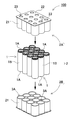
- FIG. 2 is a perspective view illustrating the power supply device according to the first embodiment.
- FIG. 2 is an exploded perspective view of the power supply device of FIG. 1.
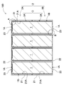
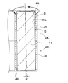
- FIG. 3 is a vertical sectional view taken along line III-III of the power supply device of FIG. 1.
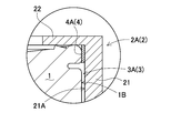
- FIG. 4 is an enlarged sectional view of a main part of a region surrounded by A of the power supply device of FIG. 3.
- FIG. 4 is an enlarged sectional view of a main part of a region surrounded by B in the power supply device of FIG. 3.
- FIG. 4 is a schematic cross-sectional view showing a state where a secondary battery cell rotates by vibration.
- FIG. 3 is a plan view of a lower holder unit of FIG. 2. It is a top view of a lower holder unit concerning a modification.
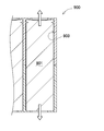
- FIG. 5 is a vertical sectional view of a power supply device according to a second embodiment. It is a vertical sectional view showing the conventional power supply device.
- FIG. 1 is a perspective view showing a power supply device 100 according to the first embodiment
- FIG. 2 is an exploded perspective view of the power supply device 100 in FIG. 1
- FIG. 3 is a vertical sectional view taken along line III-III in FIG. 4 is an enlarged cross-sectional view of a main part of a region surrounded by A of the power supply device 100 of FIG. 3
- FIG. 5 is an enlarged cross-sectional view of a main part of a region surrounded by B of the power supply device 100 of FIG. 3
- FIG. FIG. 7 is a schematic cross-sectional view showing how the cell 1 is rotated by vibration
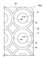
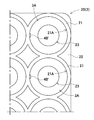
- FIG. 7 is a plan view of a lower holder unit in FIG. 2, and FIG. 8 is a plan view of a lower holder unit according to a modification.
- the power supply device 100 shown in these figures includes a battery holder 2 and a plurality of secondary battery cells 1 housed in the battery holder 2.
- end electrodes at both ends of a plurality of secondary battery cells 1 arranged at fixed positions in a battery holder 2 are connected by a lead plate to form a battery core pack. It is stored in the outer case. (Secondary battery cell 1)
- the electrode body is housed in a cylindrical outer can, filled with an electrolytic solution, and the opening of the outer can is sealed with a sealing plate.
- Both end surfaces 1A of the secondary battery cell 1 have positive and negative end surface electrodes provided at the bottom surface of the outer can and at the center of the sealing plate.
- the secondary battery cell 1 having positive and negative end face electrodes at both ends is disposed in a parallel posture to the battery holder 2, and the end face electrodes at both ends are exposed from the electrode window 23 of the battery holder 2, and are connected in parallel and / or with a lead plate. Or they are connected in series.
- the secondary battery cell 1 is a lithium ion secondary battery.
- the outer can and the sealing plate can be made of aluminum or an aluminum alloy.
- the present invention does not specify the secondary battery cell 1 as a lithium ion secondary battery, but includes all non-aqueous electrolyte secondary batteries, nickel-metal hydride batteries, and other currently used or developed secondary batteries. Battery can be used. (Battery holder 2)
- the battery holder 2 has a plurality of rechargeable battery cells 1 in a posture parallel to each other, and has both ends arranged on the same plane and arranged at a fixed position. For this reason, the battery holder 2 has a plurality of cylindrical battery housings formed as spaces for holding the secondary battery cells 1.
- This battery holder 2 is formed into a predetermined shape by a resin such as a thermoplastic resin which is an insulating material.
- the battery holder 2 can preferably be made of resin having excellent flame retardancy.
- a resin for example, PC (polycarbonate) or PP (polypropylene) can be used.
- a plurality of secondary battery cells 1 are inserted and arranged at a fixed position in a parallel posture.
- end face electrodes provided on both end faces of the secondary battery cell 1 are arranged on the same plane and are exposed from the electrode window 23.
- the battery holder 2 has a peripheral wall 21 that covers the outer peripheral surface 1B of the secondary battery cell 1 and an end plate 22 that faces the end surface 1A of the secondary battery cell 1.
- the peripheral wall 21 and the end plate 22 A plurality of battery storage sections 3 for storing the respective secondary battery cells 1 are provided. (Battery storage unit 3)
- the battery storage unit 3 has the secondary battery cell 1 inserted inside and is arranged at a fixed position.
- the battery housing part 3 has the inner peripheral surface 21A of the peripheral wall 21 formed in an inner shape along the outer peripheral surface 1B of the secondary battery cell 1, and the secondary battery cell 1 is inserted therein and arranged at a fixed position.
- the battery storage section 3 has a columnar shape, and the secondary battery cells 1 are arranged at fixed positions.
- the cylindrical battery housing 3 has an inner diameter slightly larger than the outer diameter of the secondary battery cell 1 in order to insert the secondary battery cell 1 and place it at a fixed position.
- the surface of the peripheral wall 21 disposed between the adjacent secondary battery cells 1 has a shape along the surface of the secondary battery cell 1.
- the battery holder 2 covers both ends of the battery storage section 3 for inserting and holding the secondary battery cells 1 with end face plates 22, and the end face 1 ⁇ / b> A of the secondary battery cell 1 stored in the battery storage section 3. Positioning. On the other hand, the battery holder 2 does not completely cover both ends of the battery housing portion 3 with the end face plates 22, but opens electrode windows 23 that expose end face electrodes at both ends of the secondary battery cell 1. A lead plate can be connected to the end face electrode of the secondary battery cell 1 exposed from the electrode window 23.
- the electrode window 23 is smaller than the outer shape of the secondary battery cell 1, and arranges the secondary battery cell 1 at a fixed position of the battery housing 3.
- the battery holder 2 shown in the exploded perspective view of FIG. 2 has an inner shape of the battery housing 3 having a cylindrical shape with an inner diameter into which the secondary battery cell 1 can be inserted without displacement.
- the illustrated battery holder 2 has a plurality of battery storage sections 3 arranged in a matrix in a parallel posture.
- the battery storage units are not limited to the example of the arrangement in a matrix, and may be a shape in which the battery storage units are arranged in a multi-row and multi-stage manner in a bale stack state offset in adjacent rows.
- the battery holder 2 having this structure is characterized in that the secondary battery cells 1 can be arranged in a space-efficient manner and the whole can be made compact. Another advantage is that by saving the resin in the valleys, the amount of resin used is reduced, the manufacturing cost is reduced, and the weight is reduced.
- the shape of the battery storage section does not necessarily have to be a column, but may be a polygonal column capable of storing a secondary battery cell, for example, a regular hexagonal column or a regular octagonal column.
- the battery holder 2 shown in FIGS. 1 to 3 is divided into a pair of holder units 2A and 2B in the middle of the secondary battery cell 1 in the axial direction.
- the peripheral wall 21 is divided into two parts in the middle in the axial direction, and a pair of holder units 2A and 2B are provided with divided storage parts 3A and 3A obtained by dividing the battery storage part 3 into two parts. are doing.
- the end of the secondary battery cell 1 is inserted with the opening of the divided storage portion 3A, which is the divided end of the peripheral wall 21, as an insertion hole.
- the divided storage portions 3A of the holder units 2A and 2B formed of resin are formed in an inner shape having a predetermined draft from the end face plate 22 toward the opening.
- This battery holder 2 inserts both ends of the secondary battery cell 1 into the divided storage sections 3A, 3A of the pair of holder units 2A, 2B, and also allows the pair of holder units 2A, 2B to hold the secondary battery cell 1 from both sides. Hold and hold.
- the depth of the divided storage portion 3A is set to be approximately half the total length of the secondary battery cell 1.
- the holder units 2A and 2B receive the secondary battery cell 1 in the battery storage section 3 formed by the opposed divided storage sections 3A and 3A in a state of being connected to each other, and the outer peripheral surface 1B of the secondary battery cell 1 Is entirely covered with the peripheral wall 21. As described above, the structure in which the entire outer peripheral surface 1B of the secondary battery cell 1 is covered with the peripheral wall 21 can effectively prevent the spread of fire between adjacent batteries.
- the pair of holder units 2A and 2B are connected to each other by, for example, screwing a set screw that penetrates one holder unit 2B into the other holder unit 2A.
- the secondary battery cells 1 whose both ends are stored in the opposing divided storage portions 3A are held between the holder units 2A and 2B from both ends and pressed into the inside of the battery storage portion 3. Is done. (Lead plate)
- a lead plate (not shown) connects a plurality of secondary battery cells 1 arranged in multiple stages and multiple rows in a predetermined arrangement.
- the lead plate connects a plurality of secondary battery cells 1 in parallel, connects them in series, or connects them in series and parallel.
- the lead plate is a metal plate, and is electrically connected to the end face electrode of the secondary battery cell 1 by ultrasonic welding, resistance welding, or laser welding.
- the lead plate is made of aluminum, nickel, or nickel plating, and the outer can and the sealing plate of the secondary battery cell 1 are made of aluminum or an aluminum alloy, the connection by resistance welding becomes difficult because of the low electrical resistance of aluminum. .
- the lead plate to the end face electrode by ultrasonic welding.
- the welding force is weaker than in resistance welding. Even in a structure in which the lead plate is connected by ultrasonic welding, a stable connection state between the lead plate and the end face electrode can be maintained, and a feature that can be used safely for a long period of time can be realized.
- the battery holder 2 has a plurality of battery storage sections formed in a vertical posture. Further, the battery holder 22 horizontally separates adjacent battery storage portions in a parallel posture. In this state, the plurality of secondary battery cells 1 are held in the respective battery storage sections.
- the secondary battery cell 1 held in the battery storage unit formed in the vertical posture is held in the inclined posture in the battery storage space, even if it is vibrated in the vertical direction in the vibration test, Since the central axis of the secondary battery cell 1 is inclined from the vertical direction, the radius of rotation is increased, so that the frictional resistance is increased, the opposing force against the rotation is increased, and the rotation is effectively prevented.
- tilt mechanism 4 tilt mechanism 4
- the battery housing is provided with a tilting mechanism 4 for tilting the cylindrical central axis of the secondary battery cell 1 held here from the cylindrical central axis of the battery housing.
- a tilting mechanism 4 for tilting the cylindrical central axis of the secondary battery cell 1 held here from the cylindrical central axis of the battery housing.
- a clearance is provided between the outer periphery of the secondary battery cell 901 and the battery storage section 903 so that the secondary battery cell 901 can be stored in the battery storage section 903 during assembly. Need to be formed. For this reason, the secondary battery cell 901 was not fixed in the battery storage section 903, and could not be prevented from rotating in the battery storage section 903. In particular, since the secondary battery cells 901 also have a clearance in the vertical direction in the battery storage section 903, when vibration is applied in the vertical direction, the secondary battery cells 901 move up and down in the battery storage section 903 by the clearance. A stroke occurs.
- the secondary battery cell 901 repeats up and down due to vibration, it does not come to the same position when ascending and descending, and slightly rotates. For this reason, when the vertical movement due to the vibration is repeated, the rotational movement is repeated in the same direction, and this is accumulated and the secondary battery cell 901 is rotated. When the secondary battery cell 901 rotates in the battery housing portion 903, there is a risk that a welded portion between the end face electrode and the bus bar may be damaged or broken.
- a first convex portion 4A and The 2nd convex part 4B is provided as a tilting mechanism 4 for tilting the secondary battery cell 1 in the battery storage space.
- the first convex portion 4A protrudes from the inner surface at one end (upper right in FIG. 3) of the battery housing portion.
- the second convex portion 4B protrudes from the inner surface of the other end (lower left in FIG. 3) of the battery housing portion opposite to the first convex portion 4A with respect to the center axis of the battery housing portion.
- the secondary battery cell 1 is vibrated up and down in a posture in which its central axis (indicated by a dashed line in FIG. 6) is inclined, so that the radius of rotation for rotating it is increased. For this reason, the resistance to the rotational movement becomes considerably larger than in the case of the vertical posture shown in FIG. 10, and the rotational movement is effectively prevented.
- the secondary battery cell 1 is press-fitted and inserted into the battery storage space provided with the first convex portion 4A and the second convex portion 4B, and is fixed.
- the surface of the first protrusion 4A and the second protrusion 4B may be formed in a plate shape.
- the second convex portion 4B ' may be formed so as to project in a curved shape in plan view.
- the secondary battery cell can be abutted in a point shape narrower than the example of FIG. 7 in plan view, and the pressure can be increased to hold the secondary battery cell more strongly.
- the amount of protrusion of the first protrusion 4A is designed according to the size of the bottom surface of the secondary battery cell 1 and the inner diameter of the battery housing.
- the first protrusion 4A is formed so as to have the same amount of protrusion along the longitudinal direction of the battery housing.
- the protrusion amount is, for example, about 0.1 mm to 1 mm.
- FIG. 9 shows a cross-sectional view of a power supply device 200 according to the second embodiment.
- the power supply device 200 shown in this figure has only the first protrusion 4A as the tilt mechanism 4 of the battery holder 2, and omits the second protrusion 4B.
- the secondary battery cells 1 can be effectively tilted in the battery housing, the rotation of the secondary battery cells 1 can be suppressed and the reliability can be increased while having a simpler configuration.
- the battery can be held in the inclined position in the battery housing.
- the secondary battery cell 1 can be easily maintained in the inclined posture.
- the effect of preventing the rotation of the secondary battery cell 1 by the frictional force pressed by the first protrusion 4A is also exerted.
- the protrusion amount of the first convex portion 4A may be larger than that of the example of the first embodiment.
- the inclination angle ⁇ between the cylindrical central axis of the secondary battery cell 1 held in the battery housing and the cylindrical central axis of the battery housing is emphasized for the sake of explanation.
- the inclination angle ⁇ is preferably set to 1 ° to 2 °.
- the provision of the tilt mechanism 4 for tilting the cylindrical central axis of the secondary battery cell 1 held in the battery housing from the cylindrical central axis of the battery housing is provided.
- the rotation of the secondary battery cell 1 can be suppressed, and the welding between the electrode of the secondary battery cell 1 and the bus bar can be protected, so that the reliability can be improved.
- the process of fixing the secondary battery cell 1 in the battery holder 2 can be simplified, and the advantage that reliability can be improved at low cost is obtained.
- the power supply device of the present invention is a power supply device having a structure in which a secondary battery cell is housed in a battery holder, and particularly a vibration or impact device that can prevent the secondary battery cell from rotating inside the battery housing. It can be effectively used for electric devices that are easily affected For example, it can be suitably used as a power source for vacuum cleaners, electric tools, assisted bicycles, electric scooters, carts, electric vehicles, and the like.
Landscapes
- Chemical & Material Sciences (AREA)
- Chemical Kinetics & Catalysis (AREA)
- Electrochemistry (AREA)
- General Chemical & Material Sciences (AREA)
- Battery Mounting, Suspending (AREA)
Abstract
外装缶を円筒形とする一以上の二次電池セル(1)と、二次電池セル(1)を保持する円筒形の電池収納部(3)を形成する電池ホルダ(2)とを備える電源装置(100)であって、電池収納部(3)は、該電池収納部(3)に保持された二次電池セル(1)の円筒形の中心軸を、該電池収納部(3)の円筒形の中心軸から傾斜させる傾斜機構を備える。これにより、電池収納部(3)内で二次電池セル(1)を傾斜姿勢に保持することで、回転半径を大きくして、電池ホルダ(2)内での二次電池セル(1)の動きを抑制できる。加えて、二次電池セル(1)を電池ホルダ(2)内に固定する工程を簡素化でき、低コストで信頼性を向上できる利点が得られる。
Description
本発明は、円筒形の二次電池セルを用いた電源装置に関する。
携帯機器用や電動車両などの電源として、複数の二次電池セルを用いた電源装置が用いられている。このような二次電池セルは、外装缶を円筒形とするものがあり、円筒形二次電池セルを挿入可能な円筒状の穴を設けた電池ホルダで保持している。この構造では、円筒状の穴の内部で二次電池セルが落下の衝撃や振動等によって回転することを阻止することができない。二次電池セルは端面をバスバーと溶接しているため、二次電池セルが回転すると、接続箇所が破断することがある。
これを防止するためには、二次電池セルが円筒状の穴の内部で回転しないように、接着剤や両面テープ等で二次電池セルの外装缶を物理的に固定することが考えられる。しかしながらこの方法では接着のための別工程が必要となって製造が煩雑になりコストが高くなる問題があった。
本発明は、このような背景に鑑みてなされたものであり、その目的の一は、円筒形の二次電池セルが電池ホルダ内で回転する事態を抑制して信頼性を高めた電源装置を提供することにある。
本発明の第1の側面に係る電源装置によれば、外装缶を円筒形とする一以上の二次電池セルと、前記二次電池セルを保持する円筒形の電池収納部を形成する電池ホルダとを備える電源装置であって、前記電池収納部は、該電池収納部に保持された二次電池セルの円筒形の中心軸を、該電池収納部の円筒形の中心軸から傾斜させる傾斜機構を備えることができる。上記構成により、電池収納部内で二次電池セルを傾斜姿勢に保持することで、回転半径を大きくして、電池ホルダ内での二次電池セルの動きを抑制できる。加えて、二次電池セルを電池ホルダ内に固定する工程を簡素化でき、低コストで信頼性を向上できる利点が得られる。
また、第2の側面に係る電源装置によれば、上記構成に加えて、前記傾斜機構が、前記電池収納部の一方の端部において、内面から突出する第一凸部を備えており、前記電池収納部内に保持された前記二次電池セルを、前記外装缶の端部が前記第一凸部に押圧されて、前記電池収納部内で傾斜姿勢に保持することができる。上記構成により、二次電池セルの端部を第一凸部で押圧することで、容易に傾斜姿勢に保持できる。加えて、第一凸部で押圧する摩擦力によって二次電池セルの回転を阻止する効果も発揮される。
さらに、第3の側面に係る電源装置によれば、上記何れかの構成に加えて、前記傾斜機構が、さらに、前記電池収納部の他方の端部において、前記電池収納部の中心軸に対して前記第一凸部と反対側の内面から突出する第二凸部を備え、前記電池収納部内に保持された前記二次電池セルは、前記外装缶の端部の交差する位置をそれぞれ前記第一凸部と第二凸部で押圧されて、前記電池収納部内で傾斜姿勢に保持させることができる。上記構成により、第一凸部に加えて第二凸部でも二次電池セルを押圧して、傾斜姿勢に保持できる。
さらにまた、第4の側面に係る電源装置によれば、上記何れかの構成に加えて、前記電池ホルダが、複数の電池収納部をそれぞれ垂直姿勢に形成し、かつ隣接する電池収納部が互いに平行姿勢で水平方向に離間されており、複数の前記二次電池セルを、それぞれ、各電池収納部に保持することができる。上記構成により、垂直姿勢に形成された電池収納部内に保持された二次電池セルは、電池空間内で傾斜姿勢に保持されるため、振動試験で垂直方向に振動されても、二次電池セルの中心軸が垂直方向から傾斜されていることで回転半径が大きくなる分、摩擦抵抗が増大されて回転に対する対抗力が増して回転が効果的に阻止される。
さらにまた、第5の側面に係る電源装置によれば、上記何れかの構成に加えて、前記第一凸部を、前記電池収納部の長手方向に沿って同じ突出量となるよう形成することができる。
さらにまた、第6の側面に係る電源装置によれば、上記何れかの構成に加えて、前記第一凸部を、断面視において曲面状に突出させることができる。
さらにまた、第7の側面に係る電源装置によれば、上記何れかの構成に加えて、前記電池収納部に保持された二次電池セルの円筒形の中心軸を、該電池収納部の円筒形の中心軸から1°~2°、傾斜させることができる。
さらにまた、第8の側面に係る電源装置によれば、上記何れかの構成に加えて、前記電池ホルダは、前記電池収納部の両端を端面プレートで覆うと共に、前記端面プレートは、前記二次電池セルの端面電極を表出させる電極窓を形成することができる。
以下、図面に基づいて本発明の実施形態に係る電源装置を詳細に説明する。なお、以下の説明では、必要に応じて特定の方向や位置を示す用語(例えば、「上」、「下」、及びそれらの用語を含む別の用語)を用いるが、それらの用語の使用は図面を参照した発明の理解を容易にするためであって、それらの用語の意味によって本発明の技術的範囲が制限されるものではない。また、複数の図面に表れる同一符号の部分は同一もしくは同等の部分又は部材を示す。
さらに以下に示す実施形態は、本発明の技術思想の具体例を示すものであって、本発明を以下に限定するものではない。また、以下に記載されている構成部品の寸法、材質、形状、その相対的配置等は、特定的な記載がない限り、本発明の範囲をそれのみに限定する趣旨ではなく、例示することを意図したものである。また、一の実施の形態、実施例において説明する内容は、他の実施の形態、実施例にも適用可能である。また、図面が示す部材の大きさや位置関係等は、説明を明確にするため、誇張していることがある。
[実施形態1]
[実施形態1]
本発明の実施形態1に係る電源装置を図1~図8に示す。これらの図において、図1は実施形態1に係る電源装置100を示す斜視図、図2は図1の電源装置100の分解斜視図、図3は図1のIII-III線における垂直断面図、図4は図3の電源装置100のAで囲んだ領域の要部拡大断面図、図5は図3の電源装置100のBで囲んだ領域の要部拡大断面図、図6は二次電池セル1が振動により回転する様子を示す模式断面図、図7は図2の下方のホルダーユニットの平面図、図8は変形例に係る下方のホルダーユニットの平面図を、それぞれ示している。これらの図に示す電源装置100は、電池ホルダ2と、この電池ホルダ2内に収納される複数の二次電池セル1を備えている。この電源装置100は、電池ホルダ2で定位置に配置している複数の二次電池セル1の両端の端面電極を、リード板で接続して電池のコアパックとしており、この電池のコアパックを外装ケースに収納している。
(二次電池セル1)
(二次電池セル1)
二次電池セル1は、円筒状の外装缶に電極体を収納し、電解液を充填して外装缶の開口部を封口板で密閉している。二次電池セル1の両端面1Aは、外装缶の底面と、封口板の中央部に設けた電極を正負の端面電極としている。両端に正負の端面電極のある二次電池セル1は、電池ホルダ2に平行姿勢で配置されて、その両端の端面電極を電池ホルダ2の電極窓23から露出させて、リード板で並列及び/又は直列に接続される。二次電池セル1はリチウムイオン二次電池である。リチウムイオン二次電池である二次電池セル1は、外装缶および封口板をアルミニウムまたはアルミニウム合金とすることができる。ただ、本発明は二次電池セル1をリチウムイオン二次電池に特定するものでなく、他の非水電解質二次電池やニッケル水素電池等、現在使用され、またはこれから開発される全ての二次電池が使用できる。
(電池ホルダ2)
(電池ホルダ2)
電池ホルダ2は、図2~図3に示すように、複数の二次電池セル1を互いに平行な姿勢として、両端部を同一平面に配置して定位置に配置している。このため電池ホルダ2は、二次電池セル1を保持する空間として、円筒形の電池収納部を複数形成している。
この電池ホルダ2は、絶縁材料である熱可塑性樹脂等の樹脂によって所定の形状に成形されている。電池ホルダ2は、好ましくは難燃性に優れた樹脂製とすることができる。このような樹脂として、例えば、PC(ポリカーボネート)やPP(ポリプロピレン)が使用できる。
図2~図3に示す電池ホルダ2は、複数の二次電池セル1を挿入して平行な姿勢で定位置に配置する。この電池ホルダ2は、二次電池セル1の両端面に設けている端面電極を同一平面に配置して電極窓23から露出させる。電池ホルダ2は、二次電池セル1の外周面1Bを被覆する周壁21と二次電池セル1の端面1Aと対向する端面プレート22とを有しており、これらの周壁21と端面プレート22で各二次電池セル1を収納する複数の電池収納部3を設けている。
(電池収納部3)
(電池収納部3)
電池収納部3は、内側に二次電池セル1を挿入して定位置に配置する。電池収納部3は、周壁21の内周面21Aを二次電池セル1の外周面1Bに沿う内形として、内部に二次電池セル1を挿入して定位置に配置する。図2~図3の電池ホルダ2は電池収納部3を円柱状として二次電池セル1を定位置に配置する。円柱状の電池収納部3は、二次電池セル1を挿入して定位置に配置するために、内径を二次電池セル1の外径よりも僅かに大きくしている。この電池ホルダ2は、隣接する二次電池セル1の間に配置される周壁21の表面を、二次電池セル1の表面に沿う形状とする。
さらに、電池ホルダ2は、二次電池セル1を挿入して保持する電池収納部3の両端を端面プレート22で覆っており、電池収納部3に収納される二次電池セル1の端面1Aを位置決めしている。一方で電池ホルダ2は、電池収納部3の両端を端面プレート22で完全に覆うのでなく、二次電池セル1の両端の端面電極を露出させる電極窓23を開口している。この電極窓23から露出する二次電池セル1の端面電極にリード板を接続できるようにしている。電極窓23は、二次電池セル1の外形よりも小さく、二次電池セル1を電池収納部3の定位置に配置する。
図2の分解斜視図に示す電池ホルダ2は、電池収納部3の内形を、二次電池セル1を位置ずれなく挿入できる内径の円柱状としている。図の電池ホルダ2は、複数の電池収納部3を平行な姿勢でマトリックス状に配置している。ただ電池収納部はマトリックス状の配置例に限らず、隣接する行でオフセットさせた俵積み状態に多列多段に並べた形状としてもよい。この構造の電池ホルダ2は、二次電池セル1をスペース効率よく配置して、全体をコンパクトにできる特徴がある。また、谷間部分の樹脂を節約することで、使用する樹脂の量を少なくして製造コストを低減して軽量化できる特長もある。
なお電池ホルダ2は、電池収納部の形状を必ずしも円柱状とする必要はなく、二次電池セルを収納可能な多角柱状、例えば、正六角柱状や正八角柱状等とすることもできる。
(ホルダーユニット2A、2B)
(ホルダーユニット2A、2B)
さらに、図1~図3に示す電池ホルダ2は、二次電池セル1の軸方向の中間において、一対のホルダーユニット2A、2Bに二分割している。図に示す電池ホルダ2は、周壁21を軸方向の中間で二分割しており、一対のホルダーユニット2A、2Bには、電池収納部3を二分割してなる分割収納部3A、3Aを開口している。各ホルダーユニット2A、2Bは、周壁21の分割端である分割収納部3Aの開口部を挿通穴として二次電池セル1の端部が挿入される。樹脂で成形されるホルダーユニット2A、2Bの分割収納部3Aは、端面プレート22から開口部に向かって所定の抜き勾配を有する内形に成形されている。
この電池ホルダ2は、一対のホルダーユニット2A、2Bの分割収納部3A、3Aに二次電池セル1の両端部を挿入すると共に、一対のホルダーユニット2A、2Bで二次電池セル1を両側から挟着して保持する。各ホルダーユニット2A、2Bは、分割収納部3Aの深さを二次電池セル1の全長のほぼ半分の長さとしている。このホルダーユニット2A、2Bは、互いに連結する状態で、対向する分割収納部3A、3Aで形成される電池収納部3に二次電池セル1を収納して、二次電池セル1の外周面1Bの全体を周壁21で被覆する。このように二次電池セル1の外周面1Bの全体を周壁21で被覆する構造は、隣接する電池間の類焼を有効に防止できる。
一対のホルダーユニット2A、2Bは、例えば一方のホルダーユニット2Bを貫通する止ネジを、他方のホルダーユニット2Aにねじ込んで互いに連結される。この状態で、対向する分割収納部3Aに両端部が収納される二次電池セル1は、両端側からホルダーユニット2A、2Bに挟着されて電池収納部3の内部に圧入された状態に保持される。
(リード板)
(リード板)
図示しないリード板は、多段多列に配置している複数の二次電池セル1を所定の配列で接続する。リード板は、複数の二次電池セル1を並列に接続し、あるいは直列に接続し、あるいはまた直列と並列に接続する。リード板は金属板で、超音波溶着し、あるいは抵抗溶接し、あるいはまたレーザー溶接して二次電池セル1の端面電極に電気接続される。とくに、リード板をアルミニウム、ニッケルまたはニッケルメッキとし、二次電池セル1の外装缶および封口板をアルミニウムまたはアルミニウム合金とする場合においては、アルミニウムの電気抵抗が低いため、抵抗溶接による接続が難しくなる。このため、このような場合においては、超音波溶着により、リード板を端面電極に溶着することが好ましい。特に、本発明の電源装置100では、電池収納部3に収納される二次電池セル1の回転を、後述する傾斜機構4により効果的に阻止できるので、抵抗溶接に比較して溶着力が弱くなる超音波溶着でリード板を接続する構造においても、リード板と端面電極の安定した接続状態を維持でき、長期間にわたって安心して使用できる特徴が実現できる。
電池ホルダ2は、複数の電池収納部をそれぞれ垂直姿勢に形成している。さらに電池ホルダ22は、隣接する電池収納部を互いに平行姿勢で水平方向に離間させている。この状態で複数の二次電池セル1は、それぞれ各電池収納部に保持されている。このような構成により、垂直姿勢に形成された電池収納部内に保持された二次電池セル1は、電池収納空間内で傾斜姿勢に保持されるため、振動試験で垂直方向に振動されても、二次電池セル1の中心軸が垂直方向から傾斜されていることで回転半径が大きくなる分、摩擦抵抗が増大されて回転に対する対抗力が増して回転が効果的に阻止される。以下、詳述する。
(傾斜機構4)
(傾斜機構4)
電池収納部は、ここに保持された二次電池セル1の円筒形の中心軸を、電池収納部の円筒形の中心軸から傾斜させる傾斜機構4を備えている。このように、電池収納部内で二次電池セル1を傾斜姿勢に保持することで、回転半径を大きくして、電池ホルダ2内での二次電池セル1の動きを抑制できる。加えて、二次電池セル1を電池ホルダ2内に固定する工程を簡素化でき、低コストで信頼性を向上できる利点が得られる。傾斜機構4としては、図4に示す第一凸部4Aや図5に示す第二凸部4Bが好適に利用できる。
従来の電源装置900では、図10に示すように、組立時に二次電池セル901を電池収納部903に収納できるよう、二次電池セル901の外周と電池収納部903との間にはクリアランスを形成する必要がある。このため、二次電池セル901は電池収納部903内で固定されず、電池収納部903内で回転することを阻止できなかった。特に電池収納部903内で二次電池セル901は上下方向にもクリアランスを有しているため、上下方向に振動が加わると、クリアランス分だけ二次電池セル901が電池収納部903内を上下するストロークが生じる。このため、二次電池セル901が振動により上下を繰り返すと、上昇して降下する際に同じ位置とならず、僅かに回転が生じる。このため、振動による上下運動を繰り返すと、同じ方向に回転移動が繰り返されるため、これが蓄積して二次電池セル901の回転が生じる。二次電池セル901が電池収納部903内で回転すると、端面電極とバスバーとの溶接部分が破損したり破断が生じるリスクが生じる。
また近年は二次電池セルの安全性が重視され、国連輸送試験等の厳格な試験をクリアすることが求められている。このような安全性試験では、実使用時よりも遙かに厳しい条件で縦方向(Z方向)や横方向(XY平面方向)への振動が繰り返されるため、このような試験をクリアするには実使用以上に過酷な条件下でも回転しない相当の耐性が求められている。
そこで本実施形態においては、図3及びその拡大断面図である図4及び図5に示すように、二次電池セル1を電池収納空間内で傾斜させる傾斜機構4として、第一凸部4Aと第二凸部4Bを設けている。第一凸部4Aは、電池収納部の一方の端部(図3において右上)において、内面から突出させている。一方、第二凸部4Bは、電池収納部の他方の端部(図3において左下)において、電池収納部の中心軸に対して第一凸部4Aと反対側の内面から突出させている。これにより、電池収納部内に保持された二次電池セル1は、外装缶の端部の交差する位置をそれぞれ第一凸部4Aと第二凸部4Bで押圧されて、電池収納部内で傾斜姿勢に保持される。
このように、単に二次電池セル1の表面を押圧して摩擦で二次電池セル1の回転を阻止するのみならず、凸部の位置を工夫して筒状の電池収納部内において傾斜姿勢としたことで、図6に示すように上下方向への振動が加えられた際に、二次電池セル1を回転させるための回転半径を大きくして、回転を阻止する効果が発揮される。すなわち、電源装置100を水平面に載置して、電池収納部の中心軸(図6において二点鎖線で示す)が垂直姿勢にある状態で、垂直方向に振動が加えられると、傾斜姿勢にある二次電池セル1は、その中心軸(図6において一点鎖線で示す)が傾斜された姿勢で上下方向に振動される結果、これを回転させるための回転半径が大きくなる。このため回転移動に対する抵抗が、図10に示す垂直姿勢の場合と比べて相当に大きくなって、回転移動が効果的に阻止される。
第一凸部4Aや第二凸部4Bを設けた電池収納空間内に、二次電池セル1は圧入して挿入され、固定される。第一凸部4Aや第二凸部4Bは、図7に示すように、表面を板状に形成してもよい。あるいは、図8に示す変形例に示すように、平面視において第二凸部4B’を曲面状に突出するように形成してもよい。これにより、平面視において図7の例よりも狭い点状に二次電池セルと当接させて、圧力を高めてより強く二次電池セルを保持できる。
また 第一凸部4Aの突出量は、二次電池セル1の底面の大きさや電池収納部の内径に応じて設計される。好ましくは、電池収納部の長手方向に沿って同じ突出量となるように第一凸部4Aが形成されている。突出量は、例えば0.1mm~1mm程度とする。
[実施形態2]
[実施形態2]
以上の実施形態1では、傾斜機構4として第一凸部4Aと第二凸部4Bを対向姿勢に配置した例を説明したが、本発明はこの構成に限らず、例えば第一凸部4Aのみ、あるいは第二凸部4Bのみを設けてもよい。図9に実施形態2に係る電源装置200の断面図を示す。この図に示す電源装置200は、電池ホルダ2の傾斜機構4として、第一凸部4Aのみを設けており、第二凸部4Bを省いている。この構成においても、二次電池セル1を電池収納部内で効果的に傾斜できるので、より簡素な構成としながら二次電池セル1の回転を抑えて信頼性を高めることができる。すなわち電池収納部内に保持された二次電池セル1の外装缶の端部を第一凸部4Aで押圧することで、電池収納部内で傾斜姿勢に保持できる。この結果、二次電池セル1の端部を第一凸部4Aで押圧することで、容易に傾斜姿勢に保持できる。加えて、第一凸部4Aで押圧する摩擦力によって二次電池セル1の回転を阻止する効果も発揮される。
また第一凸部4Aの突出量を、実施形態1の例よりも大きくしてもよい。
なお図6においては、電池収納部に保持された二次電池セル1の円筒形の中心軸と、電池収納部の円筒形の中心軸との傾斜角度αを、説明のため強調して表示させているが、傾斜角度αは、1°~2°とすることが好ましい。
以上のように本発明によれば、電池収納部に保持された二次電池セル1の円筒形の中心軸を、電池収納部の円筒形の中心軸から傾斜させる傾斜機構4を備えたことで、二次電池セル1が回転することを抑えて、二次電池セル1の電極とバスバーとの溶接を保護でき、もって信頼性を高めることができる。加えて、二次電池セル1を電池ホルダ2内に固定する工程を簡素化でき、低コストで信頼性を向上できる利点が得られる。
本発明の電源装置は、二次電池セルを電池ホルダに収納する構造の電源装置であって、二次電池セルが電池収納部の内部で回転するのを防止できる電源装置として、特に振動や衝撃を受けやすい電動機器に有効に使用できる。例えば掃除機、電動工具、アシスト自転車、電動スクーター、カート、電気自動車等の電源として好適に使用できる。
100、200、900…電源装置
1、901…二次電池セル
1A…端面
1B…外周面
2…電池ホルダ
2A…ホルダーユニット
2B…ホルダーユニット
3、903…電池収納部
3A…分割収納部
4…傾斜機構
4A…第一凸部
4B、4B’…第二凸部
21…周壁
21A…内周面
22…端面プレート
23…電極窓
1、901…二次電池セル
1A…端面
1B…外周面
2…電池ホルダ
2A…ホルダーユニット
2B…ホルダーユニット
3、903…電池収納部
3A…分割収納部
4…傾斜機構
4A…第一凸部
4B、4B’…第二凸部
21…周壁
21A…内周面
22…端面プレート
23…電極窓
Claims (8)
- 外装缶を円筒形とする一以上の二次電池セルと、
前記二次電池セルを保持する円筒形の電池収納部を形成する電池ホルダと、
を備える電源装置であって、
前記電池収納部は、該電池収納部に保持された二次電池セルの円筒形の中心軸を、該電池収納部の円筒形の中心軸から傾斜させる傾斜機構を備えてなる電源装置。 - 請求項1に記載の電源装置であって、
前記傾斜機構が、前記電池収納部の一方の端部において、内面から突出する第一凸部を備えており、
前記電池収納部内に保持された前記二次電池セルは、前記外装缶の端部が前記第一凸部に押圧されて、前記電池収納部内で傾斜姿勢に保持されてなる電源装置。 - 請求項2に記載の電源装置であって、
前記傾斜機構が、さらに、前記電池収納部の他方の端部において、前記電池収納部の中心軸に対して前記第一凸部と反対側の内面から突出する第二凸部を備え、
前記電池収納部内に保持された前記二次電池セルは、前記外装缶の端部の交差する位置をそれぞれ前記第一凸部と第二凸部で押圧されて、前記電池収納部内で傾斜姿勢に保持されてなる電源装置。 - 請求項1~3のいずれか一項に記載の電源装置であって、
前記電池ホルダが、複数の電池収納部をそれぞれ垂直姿勢に形成し、かつ隣接する電池収納部が互いに平行姿勢で水平方向に離間されており、
複数の前記二次電池セルが、それぞれ、各電池収納部に保持されてなる電源装置。 - 請求項1~4のいずれか一項に記載の電源装置であって、
前記第一凸部は、前記電池収納部の長手方向に沿って同じ突出量となるよう形成されてなる電源装置。 - 請求項1~5のいずれか一項に記載の電源装置であって、
前記第一凸部は、断面視において曲面状に突出されてなる電源装置。 - 請求項1~6のいずれか一項に記載の電源装置であって、
前記電池収納部に保持された二次電池セルの円筒形の中心軸が、該電池収納部の円筒形の中心軸から1°~2°、傾斜されてなる電源装置。 - 請求項1~7のいずれか一項に記載の電源装置であって、
前記電池ホルダは、前記電池収納部の両端を端面プレートで覆うと共に、
前記端面プレートは、前記二次電池セルの端面電極を表出させる電極窓を形成してなる電源装置。
Applications Claiming Priority (2)
| Application Number | Priority Date | Filing Date | Title |
|---|---|---|---|
| JP2018117441A JP2021152987A (ja) | 2018-06-20 | 2018-06-20 | 電源装置 |
| JP2018-117441 | 2018-06-20 |
Publications (1)
| Publication Number | Publication Date |
|---|---|
| WO2019244641A1 true WO2019244641A1 (ja) | 2019-12-26 |
Family
ID=68983672
Family Applications (1)
| Application Number | Title | Priority Date | Filing Date |
|---|---|---|---|
| PCT/JP2019/022438 Ceased WO2019244641A1 (ja) | 2018-06-20 | 2019-06-06 | 電源装置 |
Country Status (2)
| Country | Link |
|---|---|
| JP (1) | JP2021152987A (ja) |
| WO (1) | WO2019244641A1 (ja) |
Families Citing this family (5)
| Publication number | Priority date | Publication date | Assignee | Title |
|---|---|---|---|---|
| US12548847B2 (en) * | 2022-12-07 | 2026-02-10 | Samsung Sdi Co., Ltd. | Rechargeable battery module |
| EP4661182A4 (en) * | 2023-01-31 | 2026-05-06 | Panasonic Energy Co Ltd | Power supply device and method for manufacturing power supply device |
| WO2025070470A1 (ja) * | 2023-09-29 | 2025-04-03 | パナソニックIpマネジメント株式会社 | 蓄電モジュール |
| WO2025070703A1 (ja) * | 2023-09-29 | 2025-04-03 | パナソニックIpマネジメント株式会社 | 蓄電モジュール |
| WO2025070469A1 (ja) * | 2023-09-29 | 2025-04-03 | パナソニックIpマネジメント株式会社 | 蓄電モジュール |
Citations (4)
| Publication number | Priority date | Publication date | Assignee | Title |
|---|---|---|---|---|
| JP2016072069A (ja) * | 2014-09-30 | 2016-05-09 | 豊田合成株式会社 | 電池モジュール |
| JP2017079184A (ja) * | 2015-10-22 | 2017-04-27 | トヨタ自動車株式会社 | 組電池の製造方法 |
| JP2017139172A (ja) * | 2016-02-05 | 2017-08-10 | トヨタ自動車株式会社 | 電池モジュールの製造方法 |
| JP2017152157A (ja) * | 2016-02-23 | 2017-08-31 | トヨタ自動車株式会社 | 電池モジュール |
-
2018
- 2018-06-20 JP JP2018117441A patent/JP2021152987A/ja active Pending
-
2019
- 2019-06-06 WO PCT/JP2019/022438 patent/WO2019244641A1/ja not_active Ceased
Patent Citations (4)
| Publication number | Priority date | Publication date | Assignee | Title |
|---|---|---|---|---|
| JP2016072069A (ja) * | 2014-09-30 | 2016-05-09 | 豊田合成株式会社 | 電池モジュール |
| JP2017079184A (ja) * | 2015-10-22 | 2017-04-27 | トヨタ自動車株式会社 | 組電池の製造方法 |
| JP2017139172A (ja) * | 2016-02-05 | 2017-08-10 | トヨタ自動車株式会社 | 電池モジュールの製造方法 |
| JP2017152157A (ja) * | 2016-02-23 | 2017-08-31 | トヨタ自動車株式会社 | 電池モジュール |
Also Published As
| Publication number | Publication date |
|---|---|
| JP2021152987A (ja) | 2021-09-30 |
Similar Documents
| Publication | Publication Date | Title |
|---|---|---|
| WO2019244641A1 (ja) | 電源装置 | |
| JP4484782B2 (ja) | 二次電池 | |
| CN103078068B (zh) | 蓄电元件 | |
| JP6519161B2 (ja) | 蓄電素子 | |
| KR20220101633A (ko) | 단부 커버 조립체, 이차 배터리, 배터리 팩 및 배터리를 이용한 장치 | |
| KR102256733B1 (ko) | 배터리 모듈 및 이를 포함하는 배터리 팩 및 전력 저장 장치 | |
| JP4611852B2 (ja) | リチウムイオン二次電池 | |
| US9692023B2 (en) | Electricity storage module | |
| JP2012009319A (ja) | 二次電池および組電池 | |
| US8216705B2 (en) | Lithium rechargeable battery | |
| US20160072117A1 (en) | Rechargeable battery having fixing terminal and battery module using the same | |
| KR101243528B1 (ko) | 전지 수납 트레이 | |
| WO2024005034A1 (ja) | 蓄電モジュール | |
| KR20150034917A (ko) | 무용접 연결을 위한 커넥터 및 이를 적용한 전지팩 | |
| JPWO2019022098A1 (ja) | 電池パック及びその製造方法 | |
| JP6565585B2 (ja) | 電池パック | |
| US7985499B2 (en) | Battery having electrode lead element with fixing member | |
| JP2005276814A (ja) | 電池、電池パック及びそれらの製造方法 | |
| KR20190069044A (ko) | 배터리 모듈 및 이를 포함하는 배터리 팩 | |
| JP2015125824A (ja) | 電源モジュールおよび蓄電素子 | |
| US9614213B2 (en) | Battery pack | |
| JP2006190611A (ja) | 電源装置 | |
| JP7680118B2 (ja) | 耐衝撃性が向上した電池パック | |
| JP2014120700A (ja) | 蓄電モジュール | |
| KR100614355B1 (ko) | 리튬이온 이차전지 |
Legal Events
| Date | Code | Title | Description |
|---|---|---|---|
| 121 | Ep: the epo has been informed by wipo that ep was designated in this application |
Ref document number: 19821924 Country of ref document: EP Kind code of ref document: A1 |
|
| NENP | Non-entry into the national phase |
Ref country code: DE |
|
| 122 | Ep: pct application non-entry in european phase |
Ref document number: 19821924 Country of ref document: EP Kind code of ref document: A1 |
|
| NENP | Non-entry into the national phase |
Ref country code: JP |