WO2019244451A1 - モータ - Google Patents
モータ Download PDFInfo
- Publication number
- WO2019244451A1 WO2019244451A1 PCT/JP2019/015445 JP2019015445W WO2019244451A1 WO 2019244451 A1 WO2019244451 A1 WO 2019244451A1 JP 2019015445 W JP2019015445 W JP 2019015445W WO 2019244451 A1 WO2019244451 A1 WO 2019244451A1
- Authority
- WO
- WIPO (PCT)
- Prior art keywords
- insulator
- storage groove
- sensor
- motor according
- teeth
- Prior art date
- Legal status (The legal status is an assumption and is not a legal conclusion. Google has not performed a legal analysis and makes no representation as to the accuracy of the status listed.)
- Ceased
Links
Images













Classifications
-
- H—ELECTRICITY
- H02—GENERATION; CONVERSION OR DISTRIBUTION OF ELECTRIC POWER
- H02K—DYNAMO-ELECTRIC MACHINES
- H02K11/00—Structural association of dynamo-electric machines with electric components or with devices for shielding, monitoring or protection
- H02K11/20—Structural association of dynamo-electric machines with electric components or with devices for shielding, monitoring or protection for measuring, monitoring, testing, protecting or switching
- H02K11/21—Devices for sensing speed or position, or actuated thereby
- H02K11/215—Magnetic effect devices, e.g. Hall-effect or magneto-resistive elements
-
- H—ELECTRICITY
- H02—GENERATION; CONVERSION OR DISTRIBUTION OF ELECTRIC POWER
- H02K—DYNAMO-ELECTRIC MACHINES
- H02K11/00—Structural association of dynamo-electric machines with electric components or with devices for shielding, monitoring or protection
- H02K11/20—Structural association of dynamo-electric machines with electric components or with devices for shielding, monitoring or protection for measuring, monitoring, testing, protecting or switching
- H02K11/25—Devices for sensing temperature, or actuated thereby
-
- H—ELECTRICITY
- H02—GENERATION; CONVERSION OR DISTRIBUTION OF ELECTRIC POWER
- H02K—DYNAMO-ELECTRIC MACHINES
- H02K3/00—Details of windings
- H02K3/46—Fastening of windings on the stator or rotor structure
Definitions
- the present invention relates to a motor, and more particularly to a motor having a built-in sensor.
- a motor having a structure in which a temperature sensor, a magnetic sensor, and the like are built in that is, a so-called sensor built-in motor is known.
- a temperature sensor is built into a motor to monitor the temperature of a coil inside the motor. This prevents the coil insulation film from deteriorating due to the temperature rise of the coil.
- Patent Documents 1 and 2 have a structure in which the temperature sensor directly contacts the coil. For this reason, there is a possibility that the insulating film of the coil is damaged by the corners of the temperature sensor, and the insulating characteristics of the coil are degraded.
- the present invention has been made to solve the above-described problems, and has as its object to provide a motor that can incorporate a sensor without affecting the insulation characteristics of the motor.
- a motor includes a rotor, a ring-shaped stator core extending radially inward and having a plurality of teeth arranged in a circumferential direction, and a plurality of teeth.
- a stator having a plurality of coils wound around the rotor, and a pair of insulators arranged on both sides of each of the plurality of teeth in the direction of the rotation axis, wherein the coils are wound around the teeth via the insulators.
- a storage groove configured to open toward the direction of the teeth portion is formed in at least one of the insulators, and the sensor is stored in the storage groove.
- Another motor includes a rotor, a ring-shaped stator core extending radially inward and having a plurality of teeth arranged in a circumferential direction, and a plurality of coils wound around each of the plurality of teeth. And a pair of insulators disposed on both sides of each of the plurality of teeth in the direction of the rotation axis. The coils are wound around the teeth via the insulators.
- a storage groove that opens in the direction is formed in at least one of the insulators, and the sensor is stored in the storage groove.
- the corners of the sensor do not damage the insulating film of the coil, it is possible to realize a motor that can incorporate the sensor without affecting the insulation characteristics of the motor.
- FIG. 2 is a cross-sectional view illustrating a structure of the motor according to the first embodiment.
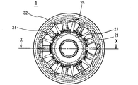
- FIG. 2 is a top view showing the structure of the motor according to the first embodiment.
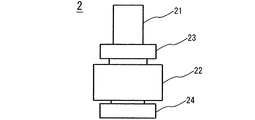
- FIG. 2 is a side view showing the structure of the rotor of the motor according to the first embodiment.
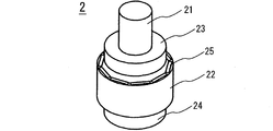
- FIG. 2 is a perspective view illustrating a structure of a rotor of the motor according to the first embodiment.
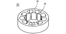
- FIG. 2 is a perspective view of a stator core of the motor according to the first embodiment.
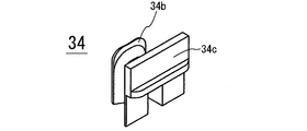
- FIG. 2 is a front perspective view of a load-side insulator of the motor according to the first embodiment.
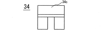
- FIG. 2 is a front view of a load-side insulator of the motor according to the first embodiment.
- FIG. 2 is a front view of a load-side insulator of the motor according to the first embodiment.
- FIG. 2 is a top view of a load-side insulator of the motor according to the first embodiment.
- FIG. 3 is a side view of a load-side insulator of the motor according to the first embodiment.
- FIG. 3 is a bottom view of the insulator on the load side of the motor according to the first embodiment.
- FIG. 3 is a cross-sectional view of a load-side insulator of the motor according to the first embodiment.
- FIG. 3 is a perspective view of the back side of the load-side insulator of the motor according to the first embodiment;
- FIG. 3 is a rear view of the insulator on the load side of the motor according to the first embodiment.
- FIG. 3 is a front perspective view of the insulator on the non-load side of the motor according to the first embodiment.
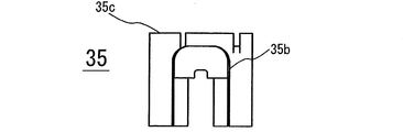
- FIG. 3 is a front view of the insulator on the non-load side of the motor according to the first embodiment.
- FIG. 3 is a top view of the insulator on the non-load side of the motor according to the first embodiment.
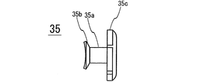
- FIG. 3 is a side view of the insulator on the non-load side of the motor according to the first embodiment.
- FIG. 3 is a bottom view of the insulator on the non-load side of the motor according to the first embodiment.
- FIG. 3 is a cross-sectional view of the insulator on the non-load side of the motor according to the first embodiment.
- FIG. 3 is a perspective view of the back side of the insulator on the non-load side of the motor according to the first embodiment.
- FIG. 3 is a rear view of the insulator on the non-load side of the motor according to the first embodiment.
- FIG. 14 is a bottom view showing the structure of the insulator on the load side of the motor according to Embodiment 2, in a state where no temperature sensor is arranged.
- FIG. 13 is a bottom view showing the structure of the insulator on the load side of the motor according to the second embodiment, in a state where a temperature sensor is arranged.
- FIG. 13 is a bottom view showing the structure of the insulator on the load side of the motor according to Embodiment 3, in which no temperature sensor is arranged.
- FIG. 13 is a bottom view showing the structure of the insulator on the load side of the motor according to the third embodiment, in a state where a temperature sensor is arranged.
- FIG. 16 is a bottom view showing the structure of the insulator on the load side of the motor according to Embodiment 4, in a state where no magnetic sensor is arranged.
- FIG. 17 is a bottom view showing the structure of the insulator on the load side of the motor according to Embodiment 4, and is a view showing a state where a magnetic sensor is arranged.
- FIG. 15 is a side view of an insulator on the non-load side of the motor according to the fifth embodiment.
- FIG. 15 is a cross-sectional view of an insulator on the non-load side of a motor according to a fifth embodiment.
- FIG. FIGS. 1 to 21 are views showing a structure of a motor 1 according to Embodiment 1 of the present invention.
- the motor 1 includes a rotor 2 and a ring-shaped stator 3.
- the direction along the shaft 21 of the rotor 2 is defined as the “rotation axis direction”.
- the direction in which the shaft 21 rotates is defined as “circumferential direction”, and the direction from the shaft 21 to the outer periphery of the stator 3 in a radial direction is defined as “radial direction”.
- FIGS. 1, 3 and 4 show the detailed structure of the rotor 2.
- the rotor 2 includes a shaft 21 as a rotating shaft, a rotor core 22 made of a magnetic material, bearings 23 and 24, and a magnet 25.
- the magnet 25 is inserted and fixed in a slot groove provided in the rotor core 22.
- the shaft 21 is fixed through the rotor core 22 and the bearings 23 and 24.
- the magnet 25 is inserted into the slot groove provided in the rotor core 22.
- the magnet 25 may be attached to the outer peripheral surface of the rotor core 22.
- a structure that does not use the magnet 25, such as a rotor core of a cage induction motor, may be used.
- the stator 3 includes a ring-shaped stator core 31 made of a magnetic material, a frame 32 fitted over the stator core 31, a coil 33, and insulators 34 and 35.
- the bracket 4 is fitted to the lower part of the frame 32.
- FIG. 5 shows a detailed structure of the stator core 31.
- a plurality of teeth portions 36 extending along the radial direction of the stator core 31 are provided on the inner peripheral side of the stator core 31.
- an insulator 34 is attached from above in the figure, and an insulator 35 is attached from below in the figure.
- a coil 33 is wound around each of the teeth portions 36 after the insulators 34 and 35 are attached.
- the insulators 34, 35 electrically insulate the teeth 36 of the stator core 31 from the coil 33, and are made of an insulating material, for example, a resin.
- the insulator 34 is mounted on the side near the load along the rotation axis direction of the rotor 2, that is, on the “load side”.
- the insulator 35 is mounted on the side opposite to the load, that is, on the “anti-load side” along the rotation axis direction of the rotor 2.
- the insulators 34 and 35 are attached from both sides along the rotation axis direction of the rotor 2.
- the bearing 23 on the load side of the rotor 2 is supported by the frame 32 of the stator 3.
- the bearing 24 on the non-load side of the rotor 2 is supported by the bracket 4 fitted to the frame 32.
- FIGS. 6 to 13 show the detailed structure of the insulator 34 attached to the load side of each tooth portion 36 of the stator core 31.
- the insulator 34 has a cover 34a that covers the teeth 36, and an inner brim 34b and an outer brim 34c that support the coil 33 wound around the cover 34a.
- a round portion having a diameter substantially equal to the wire diameter of the coil 33 to be wound is formed in the corner portion 34e of the cover portion 34a. This prevents the bending R of the coil 33 from becoming extremely small, and prevents the insulating properties of the insulating film of the coil 33 from being degraded. For this reason, it is preferable that the R dimension of the round formed at the corner 34e be large.
- each portion of the insulator 34 may be any size as long as it is equal to or greater than the minimum thickness that can be formed. Therefore, it is preferable that the thickness of the cover portion 34a in the rotation axis direction, that is, the thickness in the direction above the paper surface of FIG. 6 is determined according to the above-described R dimension.
- FIGS. 14 to 21 show the detailed structure of the insulator 35 attached to the non-load side of each tooth portion 36 of the stator core 31.
- FIG. 14 to 21 show the detailed structure of the insulator 35 attached to the non-load side of each tooth portion 36 of the stator core 31.
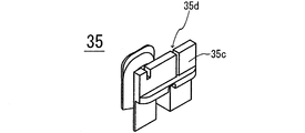
- the insulator 35 has a cover 35a that covers the teeth 36, and an inner flange 35b and an outer flange 35c that support the coil 33 wound around the cover 35a.
- a round having a diameter substantially equal to the wire diameter of the coil 33 to be wound is formed in the corner 35 e of the cover 35 a. This prevents the bending R of the coil 33 from becoming extremely small, and prevents the insulating properties of the insulating film of the coil 33 from being degraded. For this reason, it is preferable that the R dimension of the round formed in the corner 35e be large.
- the thickness of each portion of the insulator 35 may be at least the minimum thickness dimension that can be formed. Therefore, it is preferable that the thickness of the cover portion 35a in the rotation axis direction, that is, the thickness in the direction above the paper surface of FIG. 14 is determined according to the above-described R dimension.
- a coil introduction groove 35d is formed in the outer flange 35c of the insulator 35.
- a storage groove 35f for storing a temperature sensor for measuring the temperature of the coil 33 is formed on the lower surface of the cover portion 35a, that is, the surface facing the teeth portion 36. ing.
- the storage groove 35f is open toward the teeth portion 36 of the stator core 31, and is formed along the radial direction of the stator core 31.
- the end face 35g on the side of the outer brim 35c and the end face 35h on the side of the inner brim 35b are both open.
- the temperature sensor When the temperature sensor is incorporated in the motor 1, the temperature sensor is housed and fixed in the housing groove 35f.
- a fixing method of the temperature sensor press-fitting into the storage groove 35f, adhesion, resin encapsulation, or the like can be considered.
- the timing of storing the temperature sensor at the time of assembling the motor 1 may be before or after the coil 33 is wound as long as the frame 32 is fitted to the stator core 31. Is also good.
- the thickness of the portion where the storage groove 35f is formed is determined based on a requirement to form a round at the corner 35e of the cover 35a. That is, the portion where the storage groove 35f is formed is a portion which originally became a dead space.
- the dimension increase in the rotation axis direction of the insulator 35 is obtained by subtracting the thickness originally required for the insulator 35 from the outer dimension of the temperature sensor 5 and then adding the minimum moldable thickness. It is enough with the value.
- the size of the insulator 35 will increase by the outside dimension of the temperature sensor. Therefore, in the first embodiment, an increase in the dimension in the rotation axis direction is significantly suppressed as compared with the case where the temperature sensor is attached to the outside of the coil 33.
- the insulator is attached to the teeth portion of the stator, and the coil is wound over the insulator.
- a storage groove that opens toward the teeth portion is formed in the cover portion of the insulator, and the sensor is stored in the storage groove.
- the sensor while the sensor is disposed inside the coil, the sensor is prevented from directly touching the coil and damaging its insulating film. Thereby, the sensor can be built in without affecting the insulation characteristics of the motor.
- the sensor is arranged inside the coil, the coil can be easily aligned and wound, and the wound shape of the coil is not affected.
- a fixing method such as press-fitting, bonding, resin encapsulation or the like can be used, so that an additional component for fixing the sensor is unnecessary.
- Embodiment 2 FIG. Next, the structure of the motor according to Embodiment 2 of the present invention will be described with reference to FIGS. It should be noted that Embodiments 2 to 4 to be described hereinafter are derivatives that have Embodiment 1 as a basic structure. Therefore, a detailed description of the same or similar structure as in the first embodiment will be omitted.
- FIGS. 22 and 23 are bottom views of the insulator 235 according to the second embodiment, and are views of the insulator 235 viewed from the direction of the teeth portion 36 of the stator 3. This insulator 235 is attached to the non-load side of the teeth portion 36 and corresponds to the insulator 35 of the first embodiment.
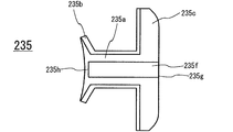
- the storage groove 235f formed on the lower surface of the cover portion 235a of the insulator 235 opens toward the teeth portion 36 of the stator core 31, and is formed along the radial direction of the stator core 31. I have. However, as best shown in FIG. 22, in the storage groove 235f, the end face 235g on the side of the outer brim 235c is open, but the end face 235h on the side of the inner brim 235b is closed.
- FIG. 23 is a diagram illustrating a state where the temperature sensor 5 is disposed in the storage groove 235f.
- the wiring of the temperature sensor 5 is taken out from the open end surface 235g of the storage groove 235f on the side of the outer brim portion 235c.
- a closed end surface 235h of the storage groove 235f on the side of the inner flange portion 235b functions as a positioning reference when the temperature sensor 5 is arranged, and one end of the temperature sensor 5 is stopped.
- At least one end of the storage groove is closed, and functions as a positioning reference when arranging the sensor.
- the sensor is prevented from protruding and interfering with the side of the rotating rotor, that is, the side of the inner brim portion.
- Embodiment 3 FIG. Next, the structure of the motor according to Embodiment 3 of the present invention will be described with reference to FIGS.
- FIGS. 24 and 25 are bottom views of the insulator 335 according to the third embodiment, and are views of the insulator 335 viewed from the direction of the teeth 36 of the stator 3.
- This insulator 235 is attached to the non-load side of the teeth portion 36 and corresponds to the insulator 35 of the first embodiment.
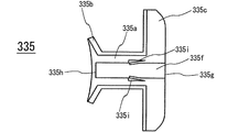
- the end surface 335g on the side of the outer flange 335c is open, but the end surface 335h on the side of the inner flange 335b is open. It is closed.
- a snap-fit mechanism 335i is provided in the storage groove 335f at a position about the outer dimension of the temperature sensor 5 from the closed end surface 335h.
- the snap fit mechanism 335i has a portion smaller than the width of the storage groove 335f, and the temperature sensor 5 can be inserted from the right side in the drawing and can be moved to the left side in the drawing.
- FIG. 25 is a diagram showing a state where the temperature sensor 5 is arranged in the storage groove 235f. As shown in this figure, once the temperature sensor 5 is moved to the closed end surface 335h, thereafter, the temperature sensor 5 cannot move to the right side in the figure.
- the storage groove is closed, and the storage groove is provided with the snap fit mechanism.
- the sensor can be easily inserted into the storage groove and can be fixed.
- Embodiment 4 FIG. Next, the structure of a motor according to Embodiment 4 of the present invention will be described with reference to FIGS.
- FIGS. 26 and 27 are bottom views of the insulator 435 according to the fourth embodiment, and are views of the insulator 435 as viewed from the direction of the teeth 36 of the stator 3.
- the insulator 435 is mounted on the non-load side of the teeth portion 36 and corresponds to the insulator 35 of the first embodiment.
- both end surface 435g on outer flange portion 435c and end surface 435h on inner flange portion 435b are both formed. is open.
- the storage groove 435f is provided with a first protrusion 435j near the end face 435h, and the second protrusion is provided at a position away from the end face 435h by about the outer dimension of the sensor 6.
- a thick portion 4351 is formed in a portion sandwiched between the first protrusion 435j and the second protrusion 435k.
- FIG. 27 is a diagram illustrating a state where the magnetic sensor 6 is disposed in the storage groove 235f.
- the magnetic sensor 6 is arranged for monitoring the magnetic flux of the rotor and estimating its rotational speed, and the tip 6a for detecting magnetism projects from the end surface 435h on the side of the inner flange 435b toward the rotor. .
- the magnetic sensor 6 is disposed in the storage groove 435f at a position of the thick portion 435l between the first protrusion 435j and the second protrusion 435k, and the first protrusion 435j and the second protrusion 435j. It is fixed by being sandwiched between 435k and thick portion 435l.
- both ends of the storage groove are open, and the storage groove has at least two protrusions and a thickness formed at a portion sandwiched between the at least two protrusions. Section is provided.
- the sensor for measuring the characteristics of the rotor can be arranged in the storage groove and can be fixed.
- Embodiment 5 FIG. Next, the configuration of a motor according to Embodiment 5 of the present invention will be described with reference to FIGS.
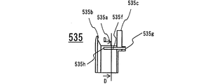
- FIG. 28 is a side view of an insulator 535 according to the fifth embodiment.
- the insulator 535 is attached to the non-load side of the teeth portion 36, and corresponds to the insulator 35 of the first embodiment.
- a housing groove 535f for housing a temperature sensor for measuring the temperature of the coil 33 is formed on one side surface of the cover 535a of the insulator 535.
- the storage groove 535f is formed along the radial direction of the stator core 31.
- the end face 535g on the side of the outer flange 535c is open, but the end face 535h on the side of the inner flange 535b is closed.
- the temperature sensor When the temperature sensor is incorporated in the motor 1, the temperature sensor is housed and fixed in the housing groove 535f.
- a fixing method of the temperature sensor press-fitting into the storage groove 535f, adhesion, resin encapsulation, or the like can be considered.
- the storage groove 535f that opens in the circumferential direction is formed on at least one side surface of the cover 535a of the insulator 535.
- the sensor can be easily inserted into the storage groove 535f, and can be fixed.
Landscapes
- Engineering & Computer Science (AREA)
- Power Engineering (AREA)
- Microelectronics & Electronic Packaging (AREA)
- Insulation, Fastening Of Motor, Generator Windings (AREA)
Abstract
モータは、ロータと、径方向内側に延びて、周方向に配列された複数のティース部を有するリング状のステータコア、および複数のティース部のそれぞれに巻き付けられた複数のコイルを有するステータと、複数のティース部のそれぞれの回転軸方向の両側に配置される一対のインシュレータとを備えている。コイルが、インシュレータを介して、ティース部のまわりに巻かれて構成され、ティース部の方向に向かって開口する収納溝が、インシュレータの少なくとも一方に形成されており、センサが、収納溝に収納されている。
Description
本発明は、モータに係り、特にセンサを内蔵したモータに関する。
従来より、温度センサ、磁気センサ等を内蔵する構造のモータ、いわゆるセンサ内蔵型モータが知られている。
例えば、温度センサは,モータ内部のコイルの温度を監視する目的で、モータに内蔵される。これにより、コイルの温度上昇によってコイルの絶縁被膜が劣化することを防止する。
通常、モータ内部のコイルの表面は、放熱面として機能するため、コイルの内側と表面とでは温度にむらが存在する。そのため、温度センサを内蔵するモータにおいて、より正確にコイルの温度を測定するために、巻回されたコイルの内側に温度センサを埋め込む技術が提案されている(例えば、特許文献1、特許文献2参照)。
しかしながら、特許文献1、2では、温度センサがコイルに直接触れる構造となっている。そのため、温度センサの角部によって、コイルの絶縁皮膜が傷つけられ、コイルの絶縁特性が低下するおそれがある。
本発明は、上記の課題を解決するためになされたものであり、モータの絶縁特性に影響を与えずにセンサを内蔵することができる、モータを提供することを目的とする。
上記の課題を解決するために、本発明に係るモータは、ロータと、径方向内側に延びて、周方向に配列された複数のティース部を有するリング状のステータコア、および複数のティース部のそれぞれに巻き付けられた複数のコイルを有するステータと、複数のティース部のそれぞれの回転軸方向の両側に配置される一対のインシュレータとを備え、コイルが、インシュレータを介して、ティース部のまわりに巻かれて構成され、ティース部の方向に向かって開口する収納溝が、インシュレータの少なくとも一方に形成されており、センサが、収納溝に収納されている。
また、本発明に係る別のモータは、ロータと、径方向内側に延びて、周方向に配列された複数のティース部を有するリング状のステータコア、および複数のティース部のそれぞれに巻き付けられた複数のコイルを有するステータと、複数のティース部のそれぞれの回転軸方向の両側に配置される一対のインシュレータとを備え、コイルが、インシュレータを介して、ティース部のまわりに巻かれて構成され、周方向に向かって開口する収納溝が、インシュレータの少なくとも一方に形成されており、センサが、収納溝に収納されている。
本発明に係るモータによれば、センサの角部がコイルの絶縁皮膜を傷つけることがないため、モータの絶縁特性に影響を与えずにセンサを内蔵することができるモータを実現できる。
以下、添付図面を参照して、本願が開示するモータの実施の形態を詳細に説明する。ただし、以下に示す実施の形態は一例であり、これらの実施の形態によって本発明が限定されるものではない。
実施の形態1.
図1~図21は、本発明の実施の形態1に係るモータ1の構造を示す図である。
図1~図21は、本発明の実施の形態1に係るモータ1の構造を示す図である。
図1、図2に示されるように、実施の形態1に係るモータ1は、ロータ2と、リング形状のステータ3とを備えている。これ以降、ロータ2のシャフト21に沿う方向を「回転軸方向」と定義する。また、シャフト21の回転する方向を「周方向」、シャフト21からステータ3の外周に放射状に向かう方向を「径方向」と定義する。
図1、図3、図4には、ロータ2の詳細な構造が示されている。ロータ2は、回転軸であるシャフト21と、磁性材料によって構成されるロータコア22と、軸受ベアリング23,24と、磁石25とを含んでいる。磁石25は、ロータコア22に設けられたスロット溝に挿入されて固定されている。シャフト21は、ロータコア22および軸受ベアリング23,24を貫通して固定されている。
なお、本実施の形態1では、ロータコア22に設けられたスロット溝に磁石25が挿入される構造であるが、ロータコア22の外周面に磁石25を貼り付ける構造であってもよい。また、かご型誘導モータのロータコアのように、磁石25を使用しない構造であってもよい。
また、図1に示されるように、ステータ3は、磁性材料によって構成されるリング形状のステータコア31と、ステータコア31の上部に嵌め合わされるフレーム32と、コイル33と、インシュレータ34,35とを含んでいる。また、フレーム32の下部には、ブラケット4が嵌め合わされている。
図5には、ステータコア31の詳細な構造が示されている。ステータコア31の内周側には、ステータコア31の径方向に沿って延びる複数のティース部36が設けられている。
各ティース部36には、図中の上方向からインシュレータ34が取り付けられる共に、図中の下方向からインシュレータ35が取り付けられる。また、インシュレータ34,35が取り付けられた後の各ティース部36には、コイル33が巻き付けられる。
インシュレータ34,35は、ステータコア31の各ティース部36とコイル33とを電気的に絶縁するものであり、絶縁材料、例えば樹脂によって構成されている。
なお、図1の断面図に示されるように、インシュレータ34は、ロータ2の回転軸方向に沿って負荷に近い側、すなわち「負荷側」に取り付けられている。また、インシュレータ35は、ロータ2の回転軸方向に沿って負荷と反対の側、すなわち「反負荷側」に取り付けられている。
換言すれば、各ティース部36について、インシュレータ34,35は、ロータ2の回転軸方向に沿って、両側から取り付けられている。
また、同じく図1の断面図に示されるように、ロータ2の負荷側の軸受ベアリング23は、ステータ3のフレーム32によって支持されている。一方、ロータ2の反負荷側の軸受ベアリング24は、フレーム32に嵌め合わされたブラケット4によって支持されている。
次に、本実施の形態1に係るインシュレータ34,35の詳細について説明する。
図6~図13には、ステータコア31の各ティース部36の負荷側に取り付けられるインシュレータ34の詳細な構造が示されている。
インシュレータ34は、ティース部36を覆うカバー部34aと、カバー部34aの上から巻き付けられるコイル33を支える内ツバ部34bおよび外ツバ部34cとを有している。
図6に示されるように、カバー部34aの角部34eには、巻き付けられるコイル33の線径と同程度のラウンドが形成されている。これにより、コイル33の曲げRが極端に小さくなることが回避され、コイル33の絶縁皮膜の絶縁特性が低下することが防止される。この理由から、角部34eに形成されるラウンドのR寸法は、大きいほうが好ましい。
一方、インシュレータ34の各部分の厚みは、成形可能な最小の厚み寸法以上であればよい。そのため、カバー部34aの回転軸方向の厚み、すなわち図6の紙面上方向の厚みは、上記のR寸法にあわせて決定されることが好ましい。
図14~図21には、ステータコア31の各ティース部36の反負荷側に取り付けられるインシュレータ35の詳細な構造が示されている。
インシュレータ35は、ティース部36を覆うカバー部35aと、カバー部35aの上から巻き付けられるコイル33を支える内ツバ部35bおよび外ツバ部35cとを有している。
図14に示されるように、カバー部35aの角部35eには、巻き付けられるコイル33の線径と同程度のラウンドが形成されている。これにより、コイル33の曲げRが極端に小さくなることが回避され、コイル33の絶縁皮膜の絶縁特性が低下することが防止される。この理由から、角部35eに形成されるラウンドのR寸法は、大きいほうが好ましい。
一方、インシュレータ35の各部分の厚みは、成形可能な最小の厚み寸法以上であればよい。そのため、カバー部35aの回転軸方向の厚み、すなわち図14の紙面上方向の厚みは、上記のR寸法にあわせて決定されることが好ましい。
また、インシュレータ35の外ツバ部35cには、コイル導入溝35dが形成されている。
さらに、図18、図19に示されるように、カバー部35aの下面、すなわちティース部36に対向する面には、コイル33の温度を測定する温度センサを収納するための収納溝35fが形成されている。
収納溝35fは、ステータコア31のティース部36に向けて開口しており、ステータコア31の径方向に沿って形成されている。また、収納溝35fにおいて、外ツバ部35cの側の端面35gと内ツバ部35bの側の端面35hとは、ともに開いている。
モータ1の内部に温度センサを組み込む際には、この収納溝35fに温度センサを収納して固定する。温度センサの固定方法としては、収納溝35fへの圧入、接着、樹脂封入等が考えられる。
特に、コイル33から温度センサへの熱伝導を促進するためには、接着、樹脂封入等の熱伝導性の優れた方法によって固定するのが好ましい。また、モータ1の組み立て時に温度センサを収納するタイミングは、ステータコア31にフレーム32を嵌め合わせた後であれば、コイル33を巻き付ける前であってもよいし、コイル33を巻き付けた後であってもよい。
なお、先述したように、インシュレータ35において、収納溝35fが形成される部分の厚みは、カバー部35aの角部35eにラウンドを形成する要求から決定されている。すなわち、収納溝35fが形成される部分は、元々はデッドスペースとなっていた部分である。
したがって、インシュレータ35の回転軸方向、すなわち図14の紙面上方向の寸法増加は、温度センサ5の外寸からインシュレータ35に元来必要であった厚みを減算した後、成形可能な最小厚みを加算した値で済む。
これに対して、仮にコイル33の外側に温度センサを取り付ける場合には、温度センサの外寸の分だけインシュレータ35の寸法が増加してしまう。したがって、本実施の形態1では、コイル33の外部に温度センサを取り付ける場合と比較すると、回転軸方向の寸法増加が大幅に抑えられる。
以上に説明したように、本発明の実施の形態1係るモータでは、ステータのティース部にインシュレータが取り付けられており、インシュレータの上からコイルが巻き付けられている。インシュレータのカバー部には、ティース部に向けて開口する収納溝が形成されており、この収納溝内にセンサが収納されている。
したがって、センサをコイルの内側に配置しながら、センサがコイルに直接触れてその絶縁皮膜を傷つけることが防止される。これにより、モータの絶縁特性に影響を与えずにセンサを内蔵することができる。
また、センサをコイルの内側に配置しているにもかかわらず、容易にコイルを整列して巻き付けることができ、コイルの巻き付き形状に影響を与えることがない。
また、上述したように、インシュレータにおいて、元来デッドスペースとなっていた部分に収納溝が形成されるため、省スペースなセンサ内蔵型モータとすることができる。
さらに、収納溝内にセンサを固定する際には、圧入、接着、樹脂封入等の固定方法を使用することができるため、センサ固定用の追加部品が不要である。
実施の形態2.
次に、本発明の実施の形態2に係るモータの構造について、図22、図23を参照して説明する。なお、これ以降に説明する実施の形態2~4は、実施の形態1を基本構造とする派生形態である。そのため、実施の形態1と同一または同様の構造については、詳細な説明は省略する。
次に、本発明の実施の形態2に係るモータの構造について、図22、図23を参照して説明する。なお、これ以降に説明する実施の形態2~4は、実施の形態1を基本構造とする派生形態である。そのため、実施の形態1と同一または同様の構造については、詳細な説明は省略する。
図22、図23は、実施の形態2に係るインシュレータ235の下面図であり、インシュレータ235をステータ3のティース部36の方向から見た図である。このインシュレータ235は、ティース部36の反負荷側に取り付けられるものであり、実施の形態1のインシュレータ35に相当するものである。
実施の形態1と同様に、インシュレータ235のカバー部235aの下面に形成される収納溝235fは、ステータコア31のティース部36に向けて開口しており、ステータコア31の径方向に沿って形成されている。しかしながら、図22に最もよく示されるように、収納溝235fにおいて、外ツバ部235cの側の端面235gは開いているが、内ツバ部235bの側の端面235hは閉じている。
図23は、収納溝235fに温度センサ5を配置した状態を示す図である。この図に示されるように、収納溝235fの外ツバ部235cの側の開いている端面235gからは、温度センサ5の配線が取り出される。一方、収納溝の235fの内ツバ部235bの側の閉じている端面235hは、温度センサ5を配置する際の位置決め基準として機能し、温度センサ5の一端が当て止めされている。
以上説明したように、本実施の形態2では、収納溝の少なくとも一端は閉じており、センサを配置する際の位置決め基準として機能する。これにより、例えば複数のティース部のそれぞれにセンサを配置する際の位置のばらつきを防止することができる。また、センサが回転するロータの側、すなわち内ツバ部の側にはみ出して干渉することが防止される。
実施の形態3.
次に、本発明の実施の形態3に係るモータの構造について、図24、図25を参照して説明する。
次に、本発明の実施の形態3に係るモータの構造について、図24、図25を参照して説明する。
図24、図25は、実施の形態3に係るインシュレータ335の下面図であり、インシュレータ335をステータ3のティース部36の方向から見た図である。このインシュレータ235は、ティース部36の反負荷側に取り付けられるものであり、実施の形態1のインシュレータ35に相当するものである。
実施の形態2と同様に、インシュレータ335のカバー部335aの下面に形成される収納溝335fにおいて、外ツバ部335cの側の端面335gは開いているが、内ツバ部335bの側の端面335hは閉じている。また、図24に最もよく示されるように、収納溝335fには、閉じている側の端面335hから温度センサ5の外寸程度離れた位置に、スナップフィット機構335iが設けられている。スナップフィット機構335iは、収納溝335fの幅よりも小さい部分を有しており、図中の右側から温度センサ5を挿入して、図中の左側へと移動させることができる。
図25は、収納溝235fに温度センサ5を配置した状態を示す図である。この図に示されるように、ひとたび温度センサ5を閉じている側の端面335hまで移動させると、それ以降、温度センサ5は図中の右側へと移動することができなくなる。
以上説明したように、本実施の形態3では、収納溝の少なくとも一端は閉じており、収納溝にスナップフィット機構が設けられている。これにより、収納溝に簡単にセンサを挿入することができ、また固定することができる。
実施の形態4.
次に、本発明の実施の形態4に係るモータの構造について、図26、図27を参照して説明する。
次に、本発明の実施の形態4に係るモータの構造について、図26、図27を参照して説明する。
図26、図27は、実施の形態4に係るインシュレータ435の下面図であり、インシュレータ435をステータ3のティース部36の方向から見た図である。このインシュレータ435は、ティース部36の反負荷側に取り付けられるものであり、実施の形態1のインシュレータ35に相当するものである。
実施の形態2,3とは異なり、インシュレータ435のカバー部435aの下面に形成される収納溝435fにおいて、外ツバ部435cの側の端面435gと内ツバ部435bの側の端面435hとは、ともに開いている。また、図26に最もよく示されるように、収納溝435fには、端面435hの付近に第1の突起部435jが設けられており、端面435hからセンサ6の外寸程度離れた位置に第2の突起部435kが設けられている。また、第1の突起部435jと第2の突起部435kとに挟まれた部分には、肉厚部435lが形成されている。
図27は、収納溝235fに磁気センサ6を配置した状態を示す図である。磁気センサ6は、ロータの磁束を監視してその回転速度を推測するために配置されており、磁気を検知する先端部6aが内ツバ部435bの側の端面435hからロータに向けて飛び出している。
磁気センサ6は、収納溝435fにおいて、第1の突起部435jと第2の突起部435kとに挟まれた肉厚部435lの位置に配置され、第1の突起部435jと第2の突起部435kと肉厚部435lとで挟まれることによって、固定されている。
以上説明したように、本実施の形態4では、収納溝の両端は開いており、収納溝には、少なくとも2つの突起部と、少なくとも2つの突起部によって挟まれた部分に形成される肉厚部とが設けられている。これにより、ロータの特性を測定するセンサを収納溝に配置することができ、また固定することができる。
実施の形態5.
次に、本発明の実施の形態5に係るモータの構成について、図28、図29を参照して説明する。
次に、本発明の実施の形態5に係るモータの構成について、図28、図29を参照して説明する。
図28は、実施の形態5に係るインシュレータ535の側面図である。このインシュレータ535は、ティース部36の反負荷側に取り付けられるものであり、実施の形態1のインシュレータ35に相当するものである。
インシュレータ535のカバー部535aの一方の側面には、コイル33の温度を測定する温度センサを収納するための収納溝535fが形成されている。
収納溝535fは、ステータコア31の径方向に沿って形成されている。また、収納溝535fにおいて、外ツバ部535cの側の端面535gは開いているが、内側ツバ部535bの側の端面535hは閉じている。
モータ1の内部に温度センサを組み込む際には、この収納溝535fに温度センサを収納して固定する。温度センサの固定方法としては、収納溝535fへの圧入、接着、樹脂封入等が考えられる。
以上説明したように、本実施の形態5では、インシュレータ535のカバー部535aの少なくとも一方の側面に、周方向に向けて開口する収納溝535fが形成されている。これにより、収納溝535fに簡単にセンサを挿入することができ、また固定することができる。
1 モータ、2 ロータ、3 ステータ、5 温度センサ、6 磁気センサ、33 コイル、34 インシュレータ、35 インシュレータ、35a カバー部、35f 収納溝、35g 端面、35h 端面、36 ティース部、234 インシュレータ、235 インシュレータ、235a カバー部、235f 収納溝、235g 端面、235h 端面、334 インシュレータ、335 インシュレータ、335a カバー部、335f 収納溝、335g 端面、335h 端面、335i スナップフィット機構、434 インシュレータ、435 インシュレータ、435a カバー部、435f 収納溝、435g 端面、435h 端面、435j 第1の突起部、435k 第2の突起部、435l 肉厚部、535 インシュレータ、535a カバー部、535f 収納溝。
Claims (10)
- ロータと、
径方向内側に延びて、周方向に配列された複数のティース部を有するリング状のステータコア、および前記複数のティース部のそれぞれに巻き付けられた複数のコイルを有するステータと、
前記複数のティース部のそれぞれの回転軸方向の両側に配置される一対のインシュレータとを備え、
前記コイルが、前記インシュレータを介して、前記ティース部のまわりに巻かれて構成され、
前記ティース部の方向に向かって開口する収納溝が、前記インシュレータの少なくとも一方に形成されており、
センサが、前記収納溝に収納されている、モータ。 - 前記収納溝は前記ステータの径方向に沿って形成されており、前記収納溝の少なくとも一端は閉じている、請求項1に記載のモータ。
- 前記収納溝には、スナップフィット機構が設けられている、請求項2に記載のモータ。
- 前記センサは温度センサである、請求項1~3のいずれか一項に記載のモータ。
- 前記収納溝に収納される前記センサは、樹脂によって封入されている、請求項4に記載のモータ。
- 前記収納溝は前記ステータの径方向に沿って形成されており、前記収納溝の両端は開いており、
前記収納溝には少なくとも2つの突起部と、該少なくとも2つの突起部によって挟まれた部分に形成される肉厚部とが設けられている、請求項1に記載のモータ。 - 前記センサは磁気センサである、請求項6に記載のモータ。
- ロータと、
径方向内側に延びて、周方向に配列された複数のティース部を有するリング状のステータコア、および前記複数のティース部のそれぞれに巻き付けられた複数のコイルを有するステータと、
前記複数のティース部のそれぞれの回転軸方向の両側に配置される一対のインシュレータとを備え、
前記コイルが、前記インシュレータを介して、前記ティース部のまわりに巻かれて構成され、
周方向に向かって開口する収納溝が、前記インシュレータの少なくとも一方に形成されており、
センサが、前記収納溝に収納されている、モータ。 - 前記センサは温度センサである、請求項8に記載のモータ。
- 前記収納溝に収納される前記センサは、樹脂によって封入されている、請求項9に記載のモータ。
Priority Applications (1)
| Application Number | Priority Date | Filing Date | Title |
|---|---|---|---|
| JP2020525291A JPWO2019244451A1 (ja) | 2018-06-21 | 2019-04-09 | モータ |
Applications Claiming Priority (2)
| Application Number | Priority Date | Filing Date | Title |
|---|---|---|---|
| JP2018-117903 | 2018-06-21 | ||
| JP2018117903 | 2018-06-21 |
Publications (1)
| Publication Number | Publication Date |
|---|---|
| WO2019244451A1 true WO2019244451A1 (ja) | 2019-12-26 |
Family
ID=68983947
Family Applications (1)
| Application Number | Title | Priority Date | Filing Date |
|---|---|---|---|
| PCT/JP2019/015445 Ceased WO2019244451A1 (ja) | 2018-06-21 | 2019-04-09 | モータ |
Country Status (2)
| Country | Link |
|---|---|
| JP (1) | JPWO2019244451A1 (ja) |
| WO (1) | WO2019244451A1 (ja) |
Cited By (5)
| Publication number | Priority date | Publication date | Assignee | Title |
|---|---|---|---|---|
| KR20220012743A (ko) * | 2020-07-23 | 2022-02-04 | 현대모비스 주식회사 | 모터용 버스바 유닛 |
| JP7036245B1 (ja) | 2021-02-05 | 2022-03-15 | 三菱電機株式会社 | インシュレータ及び固定子 |
| JP2023006461A (ja) * | 2021-06-30 | 2023-01-18 | 株式会社ミツバ | モータ装置 |
| JP2023149022A (ja) * | 2022-03-30 | 2023-10-13 | 株式会社豊田自動織機 | 電動機 |
| WO2024127740A1 (ja) * | 2022-12-16 | 2024-06-20 | 株式会社ミツバ | モータ |
Citations (5)
| Publication number | Priority date | Publication date | Assignee | Title |
|---|---|---|---|---|
| JPS49124504U (ja) * | 1973-02-20 | 1974-10-24 | ||
| JP2008061376A (ja) * | 2006-08-31 | 2008-03-13 | Canon Inc | 駆動装置 |
| JP2013116011A (ja) * | 2011-11-30 | 2013-06-10 | Hitachi Automotive Systems Ltd | 機電一体型駆動装置 |
| JP2013172478A (ja) * | 2012-02-17 | 2013-09-02 | Nifco Inc | インシュレータ及びステータ |
| JP2016226250A (ja) * | 2015-05-29 | 2016-12-28 | 日本電産株式会社 | モータ、送風装置、および掃除機 |
-
2019
- 2019-04-09 JP JP2020525291A patent/JPWO2019244451A1/ja active Pending
- 2019-04-09 WO PCT/JP2019/015445 patent/WO2019244451A1/ja not_active Ceased
Patent Citations (5)
| Publication number | Priority date | Publication date | Assignee | Title |
|---|---|---|---|---|
| JPS49124504U (ja) * | 1973-02-20 | 1974-10-24 | ||
| JP2008061376A (ja) * | 2006-08-31 | 2008-03-13 | Canon Inc | 駆動装置 |
| JP2013116011A (ja) * | 2011-11-30 | 2013-06-10 | Hitachi Automotive Systems Ltd | 機電一体型駆動装置 |
| JP2013172478A (ja) * | 2012-02-17 | 2013-09-02 | Nifco Inc | インシュレータ及びステータ |
| JP2016226250A (ja) * | 2015-05-29 | 2016-12-28 | 日本電産株式会社 | モータ、送風装置、および掃除機 |
Cited By (10)
| Publication number | Priority date | Publication date | Assignee | Title |
|---|---|---|---|---|
| KR20220012743A (ko) * | 2020-07-23 | 2022-02-04 | 현대모비스 주식회사 | 모터용 버스바 유닛 |
| KR102832208B1 (ko) | 2020-07-23 | 2025-07-10 | 현대모비스 주식회사 | 모터용 버스바 유닛 |
| JP7036245B1 (ja) | 2021-02-05 | 2022-03-15 | 三菱電機株式会社 | インシュレータ及び固定子 |
| CN114865855A (zh) * | 2021-02-05 | 2022-08-05 | 三菱电机株式会社 | 绝缘体和定子 |
| JP2022120283A (ja) * | 2021-02-05 | 2022-08-18 | 三菱電機株式会社 | インシュレータ及び固定子 |
| CN114865855B (zh) * | 2021-02-05 | 2025-03-18 | 三菱电机株式会社 | 绝缘体和定子 |
| JP2023006461A (ja) * | 2021-06-30 | 2023-01-18 | 株式会社ミツバ | モータ装置 |
| JP2023149022A (ja) * | 2022-03-30 | 2023-10-13 | 株式会社豊田自動織機 | 電動機 |
| JP7669963B2 (ja) | 2022-03-30 | 2025-04-30 | 株式会社豊田自動織機 | 電動機 |
| WO2024127740A1 (ja) * | 2022-12-16 | 2024-06-20 | 株式会社ミツバ | モータ |
Also Published As
| Publication number | Publication date |
|---|---|
| JPWO2019244451A1 (ja) | 2020-12-17 |
Similar Documents
| Publication | Publication Date | Title |
|---|---|---|
| WO2019244451A1 (ja) | モータ | |
| CN205489998U (zh) | 马达 | |
| US9041259B2 (en) | Actuator assembly having a motor with heat dissipation | |
| US20170019000A1 (en) | Rotating electric machine | |
| WO2017033917A1 (ja) | モータ | |
| JPWO2018179833A1 (ja) | モータ | |
| JP6536499B2 (ja) | モータ装置 | |
| JP2010158094A (ja) | ブラシレスモータ | |
| JP2007060844A (ja) | 磁気センサ付き回転電機 | |
| JPWO2018179831A1 (ja) | モータ | |
| CN115912756A (zh) | 马达 | |
| WO2019107074A1 (ja) | モータおよび該モータを含む電気機器 | |
| JP6693148B2 (ja) | モータ | |
| JP2013009571A (ja) | モータ | |
| US9960653B2 (en) | Driving device having sealing member with first and second annular protrusions | |
| JP2017208872A (ja) | 回転電機 | |
| JP2019068525A (ja) | モータ | |
| US11063503B2 (en) | Brushless motor | |
| JP2006333614A (ja) | 回転電機およびその製造方法 | |
| JP3881353B2 (ja) | ステッピングモータ | |
| JP5368524B2 (ja) | レゾルバステータ構造 | |
| CN110089009A (zh) | 轴向间隙型旋转电机 | |
| JP2020072500A (ja) | 回転電機 | |
| JP7062042B1 (ja) | 回転電機 | |
| WO2019189526A1 (ja) | ステータおよびモータ |
Legal Events
| Date | Code | Title | Description |
|---|---|---|---|
| 121 | Ep: the epo has been informed by wipo that ep was designated in this application |
Ref document number: 19821500 Country of ref document: EP Kind code of ref document: A1 |
|
| ENP | Entry into the national phase |
Ref document number: 2020525291 Country of ref document: JP Kind code of ref document: A |
|
| NENP | Non-entry into the national phase |
Ref country code: DE |
|
| 122 | Ep: pct application non-entry in european phase |
Ref document number: 19821500 Country of ref document: EP Kind code of ref document: A1 |