WO2019239778A1 - 車両制御装置、割り込み情報管理方法及び割り込み情報管理プログラム - Google Patents
車両制御装置、割り込み情報管理方法及び割り込み情報管理プログラム Download PDFInfo
- Publication number
- WO2019239778A1 WO2019239778A1 PCT/JP2019/019304 JP2019019304W WO2019239778A1 WO 2019239778 A1 WO2019239778 A1 WO 2019239778A1 JP 2019019304 W JP2019019304 W JP 2019019304W WO 2019239778 A1 WO2019239778 A1 WO 2019239778A1
- Authority
- WO
- WIPO (PCT)
- Prior art keywords
- vehicle control
- control device
- identifier
- vehicle
- interrupt information
- Prior art date
- Legal status (The legal status is an assumption and is not a legal conclusion. Google has not performed a legal analysis and makes no representation as to the accuracy of the status listed.)
- Ceased
Links
Images


Classifications
-
- G—PHYSICS
- G06—COMPUTING OR CALCULATING; COUNTING
- G06F—ELECTRIC DIGITAL DATA PROCESSING
- G06F9/00—Arrangements for program control, e.g. control units
- G06F9/06—Arrangements for program control, e.g. control units using stored programs, i.e. using an internal store of processing equipment to receive or retain programs
- G06F9/46—Multiprogramming arrangements
- G06F9/48—Program initiating; Program switching, e.g. by interrupt
- G06F9/4806—Task transfer initiation or dispatching
- G06F9/4812—Task transfer initiation or dispatching by interrupt, e.g. masked
-
- G—PHYSICS
- G06—COMPUTING OR CALCULATING; COUNTING
- G06F—ELECTRIC DIGITAL DATA PROCESSING
- G06F9/00—Arrangements for program control, e.g. control units
- G06F9/06—Arrangements for program control, e.g. control units using stored programs, i.e. using an internal store of processing equipment to receive or retain programs
- G06F9/44—Arrangements for executing specific programs
- G06F9/455—Emulation; Interpretation; Software simulation, e.g. virtualisation or emulation of application or operating system execution engines
- G06F9/45533—Hypervisors; Virtual machine monitors
- G06F9/45558—Hypervisor-specific management and integration aspects
-
- G—PHYSICS
- G06—COMPUTING OR CALCULATING; COUNTING
- G06F—ELECTRIC DIGITAL DATA PROCESSING
- G06F9/00—Arrangements for program control, e.g. control units
- G06F9/06—Arrangements for program control, e.g. control units using stored programs, i.e. using an internal store of processing equipment to receive or retain programs
- G06F9/46—Multiprogramming arrangements
- G06F9/54—Interprogram communication
-
- F—MECHANICAL ENGINEERING; LIGHTING; HEATING; WEAPONS; BLASTING
- F02—COMBUSTION ENGINES; HOT-GAS OR COMBUSTION-PRODUCT ENGINE PLANTS
- F02D—CONTROLLING COMBUSTION ENGINES
- F02D41/00—Electrical control of supply of combustible mixture or its constituents
- F02D41/24—Electrical control of supply of combustible mixture or its constituents characterised by the use of digital means
- F02D41/26—Electrical control of supply of combustible mixture or its constituents characterised by the use of digital means using computer, e.g. microprocessor
- F02D41/266—Electrical control of supply of combustible mixture or its constituents characterised by the use of digital means using computer, e.g. microprocessor the computer being backed-up or assisted by another circuit, e.g. analogue
Definitions
- the present invention relates to a vehicle control device, an interrupt information management method, and an interrupt information management program.
- Such application migration can be easily performed in a distributed computing environment composed of highly versatile hardware devices. However, in an environment that includes many dedicated vehicle devices specialized for one function, such as an automobile, the application can be transferred to another device without interrupting the connection with the vehicle device that supplies the data required by the application. Difficult to migrate.
- Patent Document 1 discloses “a computer system integrated with a vehicle user interface, wherein the computer system includes a processing system including a multi-core processor, and the processing A system provides virtualization to a first guest operating system at one or more first cores of the multi-core processor and a second guest at one or more second different cores of the multi-core processor Configured to provide virtualization to an operating system, wherein the first guest operating system is configured for reliable operation, and the virtualization is configured such that the operation of the second guest operating system is the first guest operating system. Suspend the reliable operation of the system Preventing the door, it is described a computer system. "
- Patent Document 1 an in-vehicle computerized user interface is described. According to the invention in Patent Document 1, in order to prevent the operation of one operating system from interfering with the operation of another operating system, a plurality of different operating systems that operate substantially independently are provided. However, in Patent Document 1, application migration in an automobile network is not considered, and when migrating an application, connection with a vehicle device that supplies data required by the application is interrupted. Will be limited.
- the present invention transfers an interrupt signal generated between a hardware device and an application by a virtualization management unit (for example, a hypervisor), thereby reducing a delay caused by data transfer and the like, and making the application flexible and quick.
- a virtualization management unit for example, a hypervisor
- one of the representative aspects of the present invention is a first vehicle control device that can be connected to a vehicle device, and the first vehicle control device includes a plurality of virtualization managements.
- the second identifier that uniquely identifies the virtualization management unit implemented in the first vehicle control device, and the third identifier that uniquely identifies the application software are associated with each other
- a mapping table is stored, and the arithmetic unit receives the interrupt information including the first identifier from the vehicle device, and based on the mapping table, the first vehicle control device From among the plurality of virtualization management unit definitive determines the virtualization management unit as the transfer destination of the interrupt signal request, the vehicle control apparatus characterized by.
- an interrupt signal generated between a hardware device and an application is transferred by a virtualization management unit, thereby reducing a delay that occurs in data transfer and the like, and transferring an application flexibly and quickly.
- FIG. 1 is a schematic diagram showing an automobile network according to an embodiment of the present invention.
- FIG. 2 is a diagram illustrating a mapping table in the first embodiment.
- FIG. 3 is a diagram illustrating a data processing system for transferring an interrupt signal from an unchangeable vehicle device according to the first embodiment to an application.
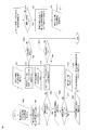
- FIG. 4 is a flowchart showing an operation of transferring an interrupt signal from an invariable vehicle device according to the first embodiment to an application.
- FIG. 5 is a diagram illustrating a mapping table in the second embodiment.
- FIG. 6 is a diagram showing a data processing system for transferring an interrupt signal from a changeable vehicular device in the second embodiment to an application.
- FIG. 7 is a flowchart showing an operation of transferring an interrupt signal from a vehicular device that can be changed to the application in the second embodiment.
- the present invention transfers an interrupt signal generated in communication with a hardware device such as a vehicle device to a desired application regardless of a device in which application software (hereinafter also referred to as “application”) is currently installed.
- application application software
- the application migration means a transition from one operating environment (a logical space constructed by an ECU, a server device, and a cloud server) to another operating environment.
- an application running in a virtualization management unit implemented on one device for example, a hardware device
- a typical electronic processing environment includes a hardware layer that provides hardware resources such as RAM and CPU, a hypervisor layer that manages the operation of one or more virtual machines, and an OS (Operating System) for each virtual machine. ) And the application layer on which the application software runs.
- the hypervisor assigns resources to supervisors and application software implemented in lower layers as the uppermost control program in this structure, and accepts communication with external devices.
- the virtualization management unit in the present invention may be a hypervisor or a supervisor. However, it is desirable to realize the virtualization manager as a hypervisor in consideration of minimizing the delay that occurs in interrupt information transfer.
- the embodiment is described using the hypervisor as an example of the virtualization management unit, but the present invention is not limited to this, and a configuration using a virtualization management unit other than the hypervisor may be used. .
- Application migration in automotive networks is an important part of realizing next-generation automotive architectures, and technology that allows flexible and rapid transfer of interrupt signals and free application migration to enable such architectures Is required.
- the present invention transfers an interrupt signal generated between a hardware device and an application to a destination application by an interrupt transfer unit mounted on a virtualization management unit (for example, a hypervisor), so that the hardware device
- a virtualization management unit for example, a hypervisor
- this problem is solved by using a virtualization management unit (that is, a hypervisor) mounted on each SOC of a vehicle control device mounted on an automobile. That is, the virtualization management unit of each SOC has a storage unit that manages a mapping table composed of a plurality of mutually independent name spaces (hereinafter also referred to as “name spaces”).
- This storage unit is a storage medium that stores the above-described mapping table in a form that can be accessed by the interrupt transfer unit.
- a semiconductor memory element such as a RAM (Random Access Memory), a flash memory (Flash Memory), or the like It may be realized by a hard disk, an optical disk or the like.
- the above-mentioned name space is an IRQ name space that identifies an IRQ (Interrupt Service Request), an application name space that uniquely identifies an application running on a hypervisor in the system (hereinafter referred to as A name space), and an SoC
- the hypervisor name space (hereinafter referred to as H name space) that uniquely identifies the hypervisor that is implemented in the data transmission path name space (hereinafter referred to as “connection name space”) for identifying the transmission paths that can be used in the SoC Say).
- Each of these IRQ name space, H name space, A name space, and connection name space is used to uniquely identify a first identifier that uniquely identifies interrupt information from a vehicle device, and a virtualization manager. It functions as a second identifier, a third identifier for uniquely identifying an application, and a fourth identifier for uniquely identifying a connection (that is, a network path) for transmitting interrupt information.
- the mapping table described above is a table for mapping one name space to another name space, and includes an IRQ name to A name table, an A name to H name table, and an H name to connection table.
- the interrupt transfer unit can specify the control device to which the generated interrupt signal is transferred by referring to these mapping tables, and transfer the interrupt signal. As a result, even when the application is transferred to a control device different from the control device physically connected to the vehicle device, communication between the vehicle device that generated the interrupt signal and the application that manages the vehicle device is performed. Not interrupted.
- FIG. 1 is a schematic diagram showing an automobile network 100 according to the first embodiment of the present invention.
- the automobile network 100 includes a vehicle device 105 and vehicle control devices 110, 120, 130, and 140.
- the vehicle control device is a device that is mounted inside an automobile and comprehensively controls various systems in the automobile using electronic circuits.
- the vehicle control device has various functions of the system such as an engine, a motor, a meter, a transmission, a brake, an air bag, a lamp, a power steering, a power window, a car air conditioner, a vehicle-side receiver of an electronic key, a car audio, a car navigation It may be an ECU (Electronic Control Unit) to be controlled.
- Each of these vehicle control devices has one or more SOCs (System-on-a-chip).
- a virtualization management unit such as one or a plurality of hypervisors is mounted on each SOC.
- Each of these virtualization management units is included in a vehicle control device (for example, ECU) having a different configuration.
- vehicle control device having a different configuration means that the respective vehicle control devices are devices that are physically independent of each other.
- hardware for example, the number of CPUs, memory capacity, sensor type
- software for example, application functions
- each virtualization management unit implements one or more virtual machines. Furthermore, applications that control various systems of the automobile described above are installed in each virtual machine. This application includes, for example, an application that detects the temperature of the engine, an application that causes a camera mounted on a car to capture an image, an application that identifies an obstacle in the captured image, and the like. Note that, here, an automobile including four vehicle control devices has been described as an example, but the present invention is not limited to this, and may be an automobile equipped with more vehicle control devices or fewer vehicle control devices. Good.
- the vehicle device is a dedicated device that is mounted inside the automobile and performs a predetermined function.
- Examples of the vehicle device include a camera, a thermometer, a vehicle speed sensor, a pneumatic sensor, a battery voltage sensor, and the like.
- Each of these vehicle devices 105 is connected to one vehicle control device and controlled.
- These vehicular devices 105 may be non-changeable devices (devices that cannot execute arbitrary programs) or may be changeable devices (devices that can execute arbitrary programs).
- the changeable device can take part of the function of the interrupt transfer unit, so the processing flow is different compared to the case where an unchangeable device is used.
- the process and flow in the case where a non-changeable device is used and the process flow in the case where a changeable device is used will be described with reference to FIGS. 4 and 7, respectively.
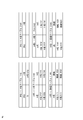
- the mapping table shown in FIG. 2 is a diagram illustrating an example of a mapping table when an unchangeable device is used as a vehicle device.
- the mapping table in the present embodiment includes an IRQ indicating which application a certain IRQ (processing request included in interrupt information) corresponds to A name tables 1142 and 3142, and each application includes The A name to H name tables 1143 and 3143 indicating which hypervisor is controlled, and the H name to connection tables 1144 and 3144 indicating paths for accessing the respective hypervisors are included.
- These mapping tables may be stored in an interrupt transfer unit included in a hypervisor layer mounted on each vehicle control device.
- mapping tables 1142, 1143, and 1144 may be stored in the vehicle control device 1300 shown in FIG. 3, and the mapping tables 3142, 3143, and 3144 may be stored in the vehicle control device 3300 (not shown).
- the interrupt transfer unit can specify a transmission destination to which the interrupt is transferred by referring to these mapping tables.
- the interrupt transfer unit first refers to the A name table 1142 from the IRQ, and applies to the application targeted by the interrupt (for example, an application corresponding to the A name 1212). ). After identifying the application, the interrupt transfer unit refers to the A name to the H name table 1143 to identify the hypervisor on which the identified application is mounted (for example, a hypervisor corresponding to the H name 1141).
- the interrupt transfer unit After identifying the hypervisor, the interrupt transfer unit refers to the connection table 1144 from the H name and identifies a connection (for example, connection 1031) for accessing the identified hypervisor. Thus, the interrupt transfer unit can transfer the generated interrupt signal to the application to which the interrupt signal corresponds via the hypervisor.
- a connection for example, connection 1031
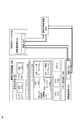
- FIG. 3 is a diagram showing a data processing system for transferring an interrupt signal from an unchangeable vehicle device according to the first embodiment of the present invention to an application.
- the data processing system includes a vehicle control device 1300, a vehicle device 2300, and a vehicle control device 3300 as shown in FIG.
- the vehicle control devices 1300 and 3300 are devices that comprehensively control various systems in an automobile using electronic circuits.
- the vehicle device 2300 is an apparatus for performing predetermined functions such as a camera, a thermometer, a vehicle speed sensor, and an air pressure sensor.
- the vehicle control device includes a CPU 1010 and a CPU 1020.
- FIG. 3 shows a vehicle control apparatus including two CPUs as an example, the number of CPUs is not limited in the present invention, and a configuration including n CPUs may be used.
- the vehicle control device 1300 may be mutually connected to an external device of the vehicle device 2300 or the vehicle control device 3300, and may include an information communication unit 1030 for performing communication with the external device.
- the information communication unit 1030 exchanges data with other devices in the automobile network, and includes a connection 1031.
- the connection 1031 is an IO interface for inputting / outputting data to / from an external device.
- connection 1031 functions as a fourth identifier for uniquely identifying the network route to the vehicle control device 1300.
- FIG. 3 shows a configuration in which the vehicle control device 1300, the vehicle device 2300, and the vehicle control device 3300 are connected to each other, but the vehicle device 2300 and the vehicle control device 3300 are connected to each other. A configuration in which the vehicle control device 1300 and the vehicle device 2300 are not connected to each other is also possible.
- the vehicle control device 1300 includes a hypervisor 1100 that includes an interrupt transfer unit 1140.
- the interrupt transfer unit 1140 includes an IRQ to A name table 1142, an A name to H name table 1143, and an H name to connection table 1144, and transfers an interrupt signal generated from a vehicle device.
- the arithmetic unit is a software module that performs arithmetic operations such as logical operations and four arithmetic operations, and may be included in a virtualization management unit such as the hypervisor 1100.
- the expression “included” means that the function of the calculation unit is processed by the virtualization management unit.
- the calculation unit is substantially controlled by the virtualization management unit, and the calculation unit is on the virtualization management unit. It includes both aspects when implemented and controlled by the virtualization manager. As described above, by mounting the arithmetic unit in the virtualization management unit, the process of transferring interrupt information can be performed in the hypervisor layer, and the delay occurring in the interrupt transfer can be minimized.
- the hypervisor 1100 generates a virtual environment 1200 using resources such as the CPU 1010, the CPU 1020, and the memory 1040.
- the virtual environment 1200 is a logical space for abstracting physical resources of the vehicle control device 1300 and executing virtual machines and applications independently of each other.
- an operating system such as Windows or Linux is installed as the supervisors 1210 and 1220.
- an application 1211 and an application 1222 are installed on each of the supervisors 1210 and 1220.
- these applications 1211, 1222 may be programs that process raw data acquired by the vehicle device 2300.
- each of the applications 1211, 1222 may be configured to operate simultaneously in an independent state.
- each of the applications 1211, 1222 is associated with an A name for uniquely identifying each of the networks.
- the application 1211 is associated with the A name 1212
- the application 1222 is associated with the A name 1222.
- these A names are stored in the mapping table of the interrupt transfer unit 1140 and are used to specify the hypervisor and application to which the interrupt signal should be transferred.
- the vehicle device 2300 is a dedicated device for performing predetermined functions such as a camera, a thermometer, a vehicle speed sensor, and an air pressure sensor.
- the vehicular device 2300 includes an information communication unit 2030. Similar to the information communication unit 1030 of the vehicle control device 1300, the information communication unit 2030 performs data exchange with other devices in the automobile network, and includes a connection 2031.
- the connection 2031 is an IO interface for inputting / outputting data to / from an external device.
- connection 2031 functions as a fourth identifier for uniquely identifying the vehicle control device 2300.
- the vehicular device 2300 is a non-changeable device that does not have a programmable interface, and thus has only a function of acquiring raw data and transmitting it to the vehicle control apparatus.
- the present invention is not limited to this, and the vehicular device 2300 may have another function.
- the vehicle control device 3300 is a device that comprehensively controls various systems in an automobile using electronic circuits. Since the structure and function of the vehicle control device 3300 are substantially the same as those of the vehicle control device 1300, detailed description of the same components will be omitted. Similar to the vehicle control device 1300, the vehicle control device 3300 includes physical resources such as a CPU and a memory, a hypervisor, and a virtual environment. Similarly to the vehicle control device 1300, the hypervisor of the vehicle control device 3300 and the application running on the hypervisor are identified by the H name as the second identifier and the A name as the third identifier.
- FIG. 4 is a flowchart showing an operation of transferring an interrupt signal from an unchangeable vehicle device according to the first embodiment of the present invention to an application.
- the mark “#” is used to indicate a target device / function unit, and may be an arbitrary reference sign.
- the interrupt transfer process shown in FIG. 4 is performed when an application is transferred from one hypervisor to another hypervisor of the vehicle control device.
- this processing is performed when an application (for example, the application 1211 illustrated in FIG. 3) that analyzes video data acquired by a camera (for example, the vehicle device 2300 illustrated in FIG. 3) is a hypervisor (for example, the original vehicle control device). 3 may be applied to a case where the hypervisor of another vehicle control device (for example, the hypervisor 1100 of the vehicle control device 1300 shown in FIG. 3) is transferred from the hypervisor of the vehicle control device 3300 shown in FIG. .
- This application migration may be performed for reasons such as improving the use efficiency of the overall system resources and improving quality of service (QoS) for customers.
- QoS quality of service
- the specific procedure for application migration and the application migration destination may be determined as appropriate according to restrictions such as the resource usage rate of the automobile network, application availability, network load, and time, and are not limited here.
- the applications have the same A name (that is, the A name of the application does not change from the start time to the end time), and the mapping table described above may be stored in each hypervisor of the automobile network.
- a well-known algorithm eg path finding algorithm, loop-free routing algorithm, ideal link-state algorithm, etc.
- the hypervisor may be notified of which route should be used to access the hypervisor, and the mapping table may be updated.
- this algorithm By executing this algorithm periodically (every time, an application is added / deleted / changed etc.), the mapping table of each hypervisor can be updated.
- the vehicle device (for example, the vehicle device 2300 shown in FIG. 3) generates interrupt information.
- the interrupt information is a signal that requests the CPU to interrupt the current process and forcibly execute the specified process.
- the vehicle device may generate interrupt information in order to cause the application to process the captured image after capturing the video.
- step 4001 the information communication unit of the vehicle device transmits interrupt information to a predetermined connection # via connection #.
- the information communication unit 2030 of the vehicle device 2300 illustrated in FIG. 3 may transmit interrupt information to the connection 3031 of the vehicle control device 3300 via the connection 2031.
- connection # receives interrupt information from the vehicle device.
- step 4003 the information communication unit having the connection # transmits the received interrupt information to the interrupt transfer unit in the same vehicle control device.
- step 4004 the interrupt transfer unit determines whether or not the received interrupt information is associated with H name metadata designating the destination hypervisor. If the received interrupt information is associated with H name metadata designating the destination hypervisor, the process proceeds to step 4005. If the received interrupt information is not associated with the H name metadata specifying the destination hypervisor, the process proceeds to step 4009.
- the interrupt transfer unit reads IRQ information from the received interrupt information.
- step 4010 the interrupt transfer unit searches the A name corresponding to the IRQ by referring to the A name table # from the IRQ using the IRQ information read in step 4009.
- the interrupt transfer unit determines whether an A name corresponding to the read IRQ exists from the IRQ in the A name table #.
- the interrupt transfer unit refers to the A name table 3142 from the IRQ shown in FIG. 2 using the IRQ information read in step 4009, and acquires the A name 1212 that is the A name corresponding to the IRQ. If the A name corresponding to the received IRQ is in the A name table # from the IRQ, the process proceeds to step 4012, and if not, the process ends.
- the interrupt transfer unit associates the acquired A name with the interrupt information. Specifically, the interrupt transfer unit attaches metadata specifying the A name corresponding to the application to be processed by the interrupt information to the interrupt information. As an example, the interrupt transfer unit may associate the metadata specifying the A name 1212 with the interrupt information.
- step 4013 in order to determine on which hypervisor the application corresponding to the A name acquired in step 4011 is running, the interrupt transfer unit uses the acquired A name to start from the A name.
- the H name corresponding to the A name that is, the hypervisor
- the interrupt transfer unit determines whether the H name corresponding to the acquired A name exists from the A name to the H name table #.
- the interrupt transfer unit refers to the H name table 3144 from the A name shown in FIG. 2 using the IRQ information read in step 4011, and selects the H name 1141 that is the H name corresponding to the A name 1212. get. If the H name corresponding to the received A name is in the A name to H name table #, the process proceeds to step 4015, and if not, the process ends.
- the interrupt transfer unit associates the acquired H name with the interrupt information. Specifically, the interrupt transfer unit attaches metadata specifying the H name corresponding to the hypervisor including the application to be processed by the interrupt information to the interrupt information. As an example, the interrupt transfer unit may associate the metadata specifying the H name 1141 with the interrupt information.
- step 4005 the interrupt transfer unit extracts the H name (H name associated in step 4015) from the interrupt information.
- the interrupt transfer unit may extract the H name 1141 from the interrupt information.
- step 4006 the interrupt transfer unit uses the extracted H name to determine whether the hypervisor that received the interrupt information is the same hypervisor as the hypervisor specified as the H name (that is, the transmission destination). Is installed in the same device as the hypervisor that received the interrupt information). The hypervisor that has received the interrupt information is the same hypervisor as the hypervisor specified for the associated H name (that is, the hypervisor that has received the interrupt information is the destination hypervisor) The process proceeds to step 4007, otherwise the process proceeds to step 4016.
- the interrupt transfer unit associates the interrupt information with the interrupt information in step 4012. Extract A name from interrupt information.
- the interrupt transfer unit may extract the A name 1212 from the interrupt information.
- Step 4015 the interrupt transfer unit transmits the received interrupt information to the application having the extracted A name.
- the hypervisor that received the interrupt information is the same as the hypervisor specified by the H name
- the application having the extracted A name is the same vehicle control device as the hypervisor, and the H There is no need to refer to the connection table by name.
- step 4006 If it is determined in step 4006 that the hypervisor that has received the interrupt information is not the hypervisor designated by the H name, then in step 4016, the interrupt transfer unit uses the extracted H name to By referring to the connection table # from the name, the connection # corresponding to the H name is searched.
- the interrupt transfer unit determines whether or not the connection # corresponding to the extracted H name exists in the connection table # from the H name.
- the interrupt transfer unit refers to the connection table 3143 from the H name shown in FIG. 2 using the H name 1141 extracted in step 4005, and acquires the connection 1031 which is the connection # corresponding to the H name. . If the connection # name corresponding to the received H name is in the connection table # from the H name, the process proceeds to step 4018, and if not, the process ends.
- the interrupt transfer unit transmits the interrupt information to the connection # acquired in step 4017 using the information communication unit #.
- the interrupt transfer unit transmits the interrupt information illustrated in FIG. 3 to the connection 1031 of the vehicle control device 1300 via the connection 3031 (not illustrated in FIG. 3) of the vehicle control device 3300.
- step 4019 the information communication unit of the destination vehicle control device receives the interrupt information transmitted in step 4018 via connection # and transmits it to the interrupt transfer unit in the same vehicle control device.
- the information communication unit 1030 of the vehicle control device 1300 transmits the received interrupt information to the interrupt transfer unit 1140 via the connection 1031.
- the interrupt transfer unit that has received the interrupt information transfers the interrupt information to the application to be transmitted by using the H name and the A name associated with the interrupt information by performing the processing from step 4003 described above. can do.
- mapping table in the second embodiment will be described with reference to FIGS.
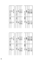
- the mapping table shown in FIG. 5 is a diagram illustrating an example of a mapping table when a changeable device is used as a vehicle device.
- the mapping table in the present embodiment includes ARQ tables 1152 and 2152 indicating which application a certain IRQ corresponds to, and which hypervisor controls each application.
- a name to H name tables 1153 and 2153, and connection names 1154 and 2154 from H names indicating connections (ie, routes) for accessing the respective hypervisors are included.
- These mapping tables may be stored in an interrupt transfer unit included in a hypervisor layer mounted on each vehicle control device.
- the mapping tables 1152, 1153, and 1154 may be stored in the vehicle control device 1300 shown in FIG. 6, and the mapping tables 2152, 2153, and 2154 may be stored in the vehicle control device 3300 (not shown).
- the interrupt transfer unit can specify a transmission destination to which the interrupt is transferred by referring to these mapping tables.
- the data processing system according to the present embodiment includes a changeable vehicle device that is responsible for part of the interrupt information transfer process. This is different from the mapping table according to the first embodiment.
- the mapping table in the present embodiment includes an H name (for example, H name 2141) for identifying a changeable vehicle device and a connection 2031 that is an input / output interface of the changeable vehicle device. This is different from the mapping table according to the first embodiment.
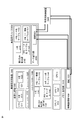
- FIG. 6 is a diagram illustrating a data processing system for transferring an interrupt signal from a changeable vehicle device according to the second embodiment of the present invention to an application.
- the data processing system includes a vehicle control device 1300, a vehicle device 2500, and a vehicle control device 3300 as shown in FIG.
- the vehicle control devices 1300 and 3300 are devices that comprehensively control various systems in an automobile using electronic circuits.
- the vehicle device 2500 is a dedicated device for performing predetermined functions such as a camera, a thermometer, a vehicle speed sensor, and an air pressure sensor.
- the data processing system according to the second embodiment differs from the data processing system according to the second embodiment in that it has a changeable vehicle device 2500 instead of the changeable vehicle device 2300.
- the vehicle device 2500 is different from the vehicle device 2300 that simply acquires and transmits raw data, in addition to the information communication unit 2030 and the connection 2031, the interrupt transfer unit 2140, the H name 2141, and the IRQ to A A name table 2142, an A name to an H name table 2143, and an H name to a connection table 2144 are included.
- the changeable vehicle device 2500 can perform a part of the interrupt transfer process (that is, a process of determining the hypervisor that is the transmission destination of the interrupt information). This can be performed more efficiently than the data processing system according to the first embodiment.
- the configuration of the data processing system according to the second embodiment is the same as that of the data processing system according to the first embodiment, except that it has a changeable vehicle device 2500 instead of the changeable vehicle device 2300. It is the same. Therefore, description of components that are substantially the same as those of the data processing system according to the first embodiment will not be repeated here.
- FIG. 7 is a flowchart showing an operation of transferring an interrupt signal from a changeable vehicle device (for example, the changeable vehicle device 2500 shown in FIG. 6) to an application in an embodiment of the present invention.
- the flowchart shown in FIG. 7 is different from the process shown in FIG. 4 in that the process of determining the hypervisor that is the transmission destination of the interrupt information is performed by a (changeable) vehicle device.
- the process for determining the hypervisor that is the destination of the interrupt information is performed by the vehicle device, thereby reducing the time required to deliver the interrupt information to the destination hypervisor and saving resources such as the CPU. Etc. are obtained.
- the mark “#” is used to indicate a target device / function unit, and may be an arbitrary reference sign.
- the interrupt transfer process shown in FIG. 7 is performed when an application is transferred from one hypervisor to another vehicle controller hypervisor.
- this processing is performed when an application (for example, the application 1211 illustrated in FIG. 6) that analyzes video data acquired by a camera (for example, the vehicle device 2500 illustrated in FIG. 6) is a hypervisor (for example, the original vehicle control device). 6 may be applied to a case in which the hypervisor of another vehicle control device (for example, the hypervisor 1100 of the vehicle control device 1300 shown in FIG. 6) is transferred from the hypervisor of the vehicle control device 3300 shown in FIG. .
- This application migration may be performed for reasons such as improving the use efficiency of resources of the entire system and improving quality of service (QoS) for customers.
- QoS quality of service
- the specific procedure for performing application migration and the application migration destination may be appropriately determined according to restrictions such as the resource usage rate of the automobile network, application availability, network load, and time, It is not limited here.
- the applications have the same A name (that is, the A name of the application does not change from the start time to the end time), and the mapping table described above may be stored in each hypervisor of the automobile network.
- a well-known algorithm eg path finding algorithm, loop-free routing algorithm, ideal link-state algorithm, etc.
- the hypervisor may be notified of which route should be used to access the hypervisor, and the mapping table may be updated. By executing this algorithm periodically (every time, an application is added / deleted / changed etc.), the mapping table of each hypervisor can be updated.
- the vehicle device (for example, the vehicle device 2500 shown in FIG. 6) generates interrupt information.
- the interrupt information is a signal that requests the CPU to interrupt the current process and forcibly execute the specified process.
- the vehicle device may generate interrupt information in order to cause the application to process the captured image after capturing the video.
- step 5001 the vehicle device that generated the interrupt information transmits the interrupt information to the interrupt transfer unit in the vehicle device.
- the vehicle device 2500 illustrated in FIG. 6 transmits interrupt information to the interrupt transfer unit 2140 of the vehicle device 2500.
- step 5002 the interrupt transfer unit that has received the interrupt information (for example, the interrupt transfer unit 2140 of the vehicle device 2500 shown in FIG. 6), the received name information that specifies the destination hypervisor. It is determined whether or not it is associated with data. If the received interrupt information is associated with H name metadata designating the destination hypervisor, the process proceeds to step 5003. If the received interrupt information is not associated with the H name metadata specifying the destination hypervisor, the process proceeds to step 5007.
- the interrupt transfer unit reads IRQ information from the received interrupt information.
- step 5008 the interrupt transfer unit refers to the A name table # from the IRQ using the IRQ information read in step 5007, and searches for the A name corresponding to the IRQ.
- the interrupt transfer unit determines whether an A name corresponding to the read IRQ exists from the IRQ in the A name table #.
- the interrupt transfer unit refers to the A name table 2152 from the IRQ shown in FIG. 6 using the IRQ information read in step 5007, and acquires the A name 1222 that is the A name corresponding to the IRQ. If the A name corresponding to the received IRQ is in the A name table # from the IRQ, the process proceeds to step 5010, and if the A name corresponding to the received IRQ is not in the A name table # from the IRQ. This process ends.
- the interrupt transfer unit associates the acquired A name with the interrupt information. Specifically, the interrupt transfer unit attaches metadata specifying the A name corresponding to the application to be processed by the interrupt information to the interrupt information. As an example, the interrupt transfer unit 2140 may associate the metadata specifying the A name 1222 with the interrupt information.
- step 5011 in order to determine on which hypervisor the application corresponding to the A name acquired in step 5008 is running, the interrupt transfer unit uses the acquired A name to start from the A name.
- the H name corresponding to the A name that is, the hypervisor
- the interrupt transfer unit determines whether the H name corresponding to the acquired A name exists from the A name to the H name table #.
- the interrupt transfer unit 2140 refers to the H name table 2153 from the A name shown in FIG. 6 using the IRQ information read in step 5007, and the H name 1141 that is the H name corresponding to the A name 1222 To get. If the H name corresponding to the received A name is in the A name to H name table #, the process proceeds to step 5013, and if not, the process ends.
- the interrupt transfer unit associates the acquired H name with the interrupt information. Specifically, the interrupt transfer unit attaches metadata specifying the H name corresponding to the hypervisor including the application to be processed by the interrupt information to the interrupt information. As an example, the interrupt transfer unit 2140 may associate the metadata specifying the H name 1141 with the interrupt information.
- step 5002 the process returns to step 5002, and it is determined whether or not the received interrupt information is associated with H name metadata specifying the destination hypervisor.
- H name metadata since the H name metadata is associated with the interrupt information in step 5013, it is determined that the H name metadata is associated, and the process proceeds to step 5003.
- the interrupt transfer unit extracts the H name (H name associated in step 5013) from the interrupt information.
- the interrupt transfer unit may extract the H name 1141 from the interrupt information.
- step 5004 the interrupt transfer unit uses the extracted H name to determine whether the hypervisor that has received the interrupt information is the same hypervisor as the hypervisor specified as the H name (that is, the transmission destination). Is installed in the same device as the hypervisor that received the interrupt information). The hypervisor that received the interrupt information is the same hypervisor as the hypervisor specified for the associated H name (that is, the hypervisor that received the interrupt information is the destination hypervisor) The process proceeds to step 5005, otherwise the process proceeds to step 5014.
- the interrupt transfer unit associates the interrupt information with the interrupt information in step 5010. Extract A name from interrupt information.
- the interrupt transfer unit 2140 may extract the A name 1222 from the interrupt information.
- step 5006 the interrupt transfer unit transmits the received interrupt information to the application having the extracted A name, and this process ends.
- the hypervisor that received the interrupt information is the same as the hypervisor specified by the H name
- the application having the extracted A name is the same vehicle control device as the hypervisor, and the H name There is no need to refer to the connection table.
- step 5004 If it is determined in step 5004 that the hypervisor that has received the interrupt information is not the hypervisor designated by the H name, the process proceeds to step 5014.
- step 5014 using the extracted H name, the interrupt transfer unit refers to the connection table # from the H name and searches for a connection # corresponding to the H name.
- the interrupt transfer unit determines whether or not the connection # corresponding to the extracted H name exists in the connection table # from the H name.
- the interrupt transfer unit 2140 uses the H name 1141 extracted in step 5003 to refer to the connection table 2154 from the H name shown in FIG. To do. If the connection # name corresponding to the received H name is in the connection table # from the H name, the process proceeds to step 45016, and if not, the process ends.
- the interrupt transfer unit transmits the interrupt information to the connection # of the destination vehicle control apparatus acquired in Step 5015 using the information communication unit #.
- the interrupt transfer unit 2140 transmits the interrupt information illustrated in FIG. 6 to the connection 1031 of the vehicle control device 1300 via the connection 2031.
- step 5017 the information communication unit of the destination vehicle control device receives the interrupt information transmitted in step 5016 via connection # and transmits it to the interrupt transfer unit in the same vehicle control device.
- the information communication unit 1030 of the vehicle control device 1300 transmits the received interrupt information to the interrupt transfer unit 1140 via the connection 1031.
- the interrupt transfer unit that has received the interrupt information transfers the interrupt information to the application to be transmitted by using the H name and the A name associated with the interrupt information by performing the processing from step 5002 described above. can do.
- the data processing system according to the second embodiment shortens the time until the interrupt signal reaches the destination vehicle control device by performing the interrupt transfer process using the changeable vehicle device. Since the processing load of the vehicle control device can be reduced, interrupt transfer processing can be performed more efficiently than the data processing system according to the first embodiment.
- the above-described vehicle control device (for example, the vehicle control devices 1300 and 3300 shown in FIG. 3) is mounted on a semiconductor substrate as an SoC and interconnected by a communication medium such as PCI Express.
- a hypervisor and an interrupt transfer unit are mounted on each SoC, and these SoCs can exchange data such as interrupt information transfer via PCI Express functioning as an information communication unit ( In other words, PCI Express functions as the information communication unit 1030 in FIG.
- the above-described vehicle control device (for example, the vehicle control devices 1300 and 3 shown in FIG. 3). 300) is mounted on an automobile as an ECU, and is interconnected to other devices (other ECUs and devices for vehicles such as cameras and sensors) by in-vehicle Ethernet.
- a hypervisor and an interrupt transfer unit are mounted on each ECU, and interrupt information can be transferred to each other via the in-vehicle Ethernet.
- a plurality of hypervisors may be mounted on each ECU. In this case, the configuration may be such that interrupt transfer ON / OFF is set for each hypervisor.
- the above-described vehicle control devices (for example, the vehicle control devices 1300 and 3300 shown in FIG. 3) are installed in different automobiles. These automobiles are interconnected by wireless communication such as LTE Advanced and 802.11. In such a case, the vehicle device (for example, the vehicle device 2300 shown in FIG. 3) is connected to only one vehicle control device.
- a hypervisor and an interrupt transfer unit are mounted on each vehicle, and these hypervisors and interrupt transfer units send different interrupt information via wireless communication such as the above-described LTE Advanced and 802.11. It can be transferred to the application installed in the car. Thereby, the application may be transferred to another automobile while maintaining the connection with the vehicle device of the original automobile.
- one of the vehicle control devices described above (for example, the vehicle control device 1300 shown in FIG. 3) is mounted on an automobile, and one or a plurality of vehicle devices (for example, the vehicle device shown in FIG. 3). 2300).
- the other control devices are installed in the data center and are interconnected to the vehicle control device mounted on the automobile via a network such as the Internet.
- the application installed in the vehicle is transferred to the control device installed in the data center, and the interrupt transfer unit of the vehicle Can transfer interrupt information from a vehicle device to a control device installed in a data center via the Internet.
- the application can utilize the resources of the control device of the data center while maintaining the connection with the vehicle device of the original automobile, and the effect of improving the performance of the application can be obtained.
- Vehicle device 110, 120, 130, 140, 150: Vehicle control device, 1100: Hypervisor, 1142, 2152, 3142: IRQ to A name table, 1143, 2153, 3143: A name to H name table, 1144, 2154, 3144: Connection table from H name, 1300, 3300: Vehicle control device, 2300: Unchangeable vehicle device, 2500: Changeable vehicle device
Landscapes
- Engineering & Computer Science (AREA)
- Software Systems (AREA)
- Theoretical Computer Science (AREA)
- Physics & Mathematics (AREA)
- General Engineering & Computer Science (AREA)
- General Physics & Mathematics (AREA)
- Small-Scale Networks (AREA)
- Combined Controls Of Internal Combustion Engines (AREA)
Priority Applications (1)
| Application Number | Priority Date | Filing Date | Title |
|---|---|---|---|
| DE112019002392.6T DE112019002392T5 (de) | 2018-06-14 | 2019-05-15 | Fahrzeugsteuergerät, verfahren zur verwaltung von interruptinformationen und programm zur verwaltung von interruptinformationen |
Applications Claiming Priority (2)
| Application Number | Priority Date | Filing Date | Title |
|---|---|---|---|
| JP2018113852A JP6838233B2 (ja) | 2018-06-14 | 2018-06-14 | 車両制御装置、割り込み情報管理方法及び割り込み情報管理プログラム |
| JP2018-113852 | 2018-06-14 |
Publications (1)
| Publication Number | Publication Date |
|---|---|
| WO2019239778A1 true WO2019239778A1 (ja) | 2019-12-19 |
Family
ID=68843265
Family Applications (1)
| Application Number | Title | Priority Date | Filing Date |
|---|---|---|---|
| PCT/JP2019/019304 Ceased WO2019239778A1 (ja) | 2018-06-14 | 2019-05-15 | 車両制御装置、割り込み情報管理方法及び割り込み情報管理プログラム |
Country Status (3)
| Country | Link |
|---|---|
| JP (1) | JP6838233B2 (OSRAM) |
| DE (1) | DE112019002392T5 (OSRAM) |
| WO (1) | WO2019239778A1 (OSRAM) |
Cited By (3)
| Publication number | Priority date | Publication date | Assignee | Title |
|---|---|---|---|---|
| CN113311738A (zh) * | 2020-02-27 | 2021-08-27 | 马自达汽车株式会社 | 车载机器控制装置 |
| CN113311737A (zh) * | 2020-02-27 | 2021-08-27 | 马自达汽车株式会社 | 车载机器控制装置 |
| EP3872631A1 (en) * | 2020-02-27 | 2021-09-01 | Mazda Motor Corporation | In-vehicle equipment controller and vehicle control system |
Citations (3)
| Publication number | Priority date | Publication date | Assignee | Title |
|---|---|---|---|---|
| JP2012145993A (ja) * | 2011-01-07 | 2012-08-02 | Mitsubishi Electric Corp | 計算機システム及び割込み制御方法及びプログラム |
| JP2013041409A (ja) * | 2011-08-15 | 2013-02-28 | Fujitsu Ltd | 情報処理装置、割込み制御方法および割込み制御プログラム |
| JP2013250950A (ja) * | 2012-06-04 | 2013-12-12 | Hitachi Ltd | 計算機システム、仮想化機構、及び計算機システムの制御方法 |
-
2018
- 2018-06-14 JP JP2018113852A patent/JP6838233B2/ja active Active
-
2019
- 2019-05-15 WO PCT/JP2019/019304 patent/WO2019239778A1/ja not_active Ceased
- 2019-05-15 DE DE112019002392.6T patent/DE112019002392T5/de active Pending
Patent Citations (3)
| Publication number | Priority date | Publication date | Assignee | Title |
|---|---|---|---|---|
| JP2012145993A (ja) * | 2011-01-07 | 2012-08-02 | Mitsubishi Electric Corp | 計算機システム及び割込み制御方法及びプログラム |
| JP2013041409A (ja) * | 2011-08-15 | 2013-02-28 | Fujitsu Ltd | 情報処理装置、割込み制御方法および割込み制御プログラム |
| JP2013250950A (ja) * | 2012-06-04 | 2013-12-12 | Hitachi Ltd | 計算機システム、仮想化機構、及び計算機システムの制御方法 |
Cited By (11)
| Publication number | Priority date | Publication date | Assignee | Title |
|---|---|---|---|---|
| CN113311738A (zh) * | 2020-02-27 | 2021-08-27 | 马自达汽车株式会社 | 车载机器控制装置 |
| CN113311737A (zh) * | 2020-02-27 | 2021-08-27 | 马自达汽车株式会社 | 车载机器控制装置 |
| EP3872631A1 (en) * | 2020-02-27 | 2021-09-01 | Mazda Motor Corporation | In-vehicle equipment controller and vehicle control system |
| EP3872632A1 (en) * | 2020-02-27 | 2021-09-01 | Mazda Motor Corporation | In-vehicle equipment control device |
| JP2021135808A (ja) * | 2020-02-27 | 2021-09-13 | マツダ株式会社 | 車載機器制御装置 |
| JP2021135806A (ja) * | 2020-02-27 | 2021-09-13 | マツダ株式会社 | 車載機器制御装置及び車両制御システム |
| CN113386686A (zh) * | 2020-02-27 | 2021-09-14 | 马自达汽车株式会社 | 车载机器控制装置和车辆控制系统 |
| CN113311737B (zh) * | 2020-02-27 | 2023-06-06 | 马自达汽车株式会社 | 车载机器控制装置 |
| CN113386686B (zh) * | 2020-02-27 | 2024-05-28 | 马自达汽车株式会社 | 车载机器控制装置和车辆控制系统 |
| JP7532806B2 (ja) | 2020-02-27 | 2024-08-14 | マツダ株式会社 | 車載機器制御装置及び車両制御システム |
| JP7567172B2 (ja) | 2020-02-27 | 2024-10-16 | マツダ株式会社 | 車載機器制御装置 |
Also Published As
| Publication number | Publication date |
|---|---|
| JP6838233B2 (ja) | 2021-03-03 |
| DE112019002392T5 (de) | 2021-03-04 |
| JP2019215822A (ja) | 2019-12-19 |
Similar Documents
| Publication | Publication Date | Title |
|---|---|---|
| US11044318B2 (en) | Efficient communications amongst computing nodes for operating autonomous vehicles | |
| CN107506258B (zh) | 用于数据备份的方法和设备 | |
| CN105531972B (zh) | 控制数据存储输入/输出请求 | |
| US8867403B2 (en) | Virtual network overlays | |
| US9838300B2 (en) | Temperature sensitive routing of data in a computer system | |
| US9628374B1 (en) | Ethernet link aggregation with shared physical ports | |
| US9537798B1 (en) | Ethernet link aggregation with shared physical ports | |
| US20190215381A1 (en) | Mobile edge computing: method to maintain reachability of apps moving between fog and cloud, using duplicate eids | |
| JP5662949B2 (ja) | 仮想ネットワーク環境におけるコピーの迂回 | |
| WO2019239778A1 (ja) | 車両制御装置、割り込み情報管理方法及び割り込み情報管理プログラム | |
| CN115858103A (zh) | 用于开放堆栈架构虚拟机之间热迁移的方法、设备及介质 | |
| KR101572689B1 (ko) | 네트워크 인터페이스 가상화 장치 및 방법 | |
| US10931581B2 (en) | MAC learning in a multiple virtual switch environment | |
| US20200304368A1 (en) | Accessing processing devices of a network device | |
| US11722368B2 (en) | Setting change method and recording medium recording setting change program | |
| US9563388B2 (en) | Sharing a hosted device in a computer network | |
| JP7632549B2 (ja) | ソースホストからターゲットホストへのライブマイグレーションを実行するシステム及び方法 | |
| CN109656674B (zh) | 一种计算机设备、虚拟化芯片及数据传输方法 | |
| CN118235373A (zh) | 虚拟网络间入口处的安全群组解析 | |
| US12500964B2 (en) | Communication system, electronic control device, and communication method | |
| CN113691624B (zh) | 基于容器的数据传输方法及设备 | |
| US20220283835A1 (en) | Library based virtual machine migration | |
| CN119052074A (zh) | 基于dpu的网络配置方法、工作节点、控制节点及设备 |
Legal Events
| Date | Code | Title | Description |
|---|---|---|---|
| 121 | Ep: the epo has been informed by wipo that ep was designated in this application |
Ref document number: 19818646 Country of ref document: EP Kind code of ref document: A1 |
|
| 122 | Ep: pct application non-entry in european phase |
Ref document number: 19818646 Country of ref document: EP Kind code of ref document: A1 |