WO2019239778A1 - Vehicle control device, interruption information management method, and interruption management program - Google Patents
Vehicle control device, interruption information management method, and interruption management program Download PDFInfo
- Publication number
- WO2019239778A1 WO2019239778A1 PCT/JP2019/019304 JP2019019304W WO2019239778A1 WO 2019239778 A1 WO2019239778 A1 WO 2019239778A1 JP 2019019304 W JP2019019304 W JP 2019019304W WO 2019239778 A1 WO2019239778 A1 WO 2019239778A1
- Authority
- WO
- WIPO (PCT)
- Prior art keywords
- vehicle control
- control device
- identifier
- vehicle
- interrupt information
- Prior art date
Links
Images


Classifications
-
- G—PHYSICS
- G06—COMPUTING; CALCULATING OR COUNTING
- G06F—ELECTRIC DIGITAL DATA PROCESSING
- G06F9/00—Arrangements for program control, e.g. control units
- G06F9/06—Arrangements for program control, e.g. control units using stored programs, i.e. using an internal store of processing equipment to receive or retain programs
- G06F9/46—Multiprogramming arrangements
- G06F9/48—Program initiating; Program switching, e.g. by interrupt
- G06F9/4806—Task transfer initiation or dispatching
- G06F9/4812—Task transfer initiation or dispatching by interrupt, e.g. masked
-
- G—PHYSICS
- G06—COMPUTING; CALCULATING OR COUNTING
- G06F—ELECTRIC DIGITAL DATA PROCESSING
- G06F9/00—Arrangements for program control, e.g. control units
- G06F9/06—Arrangements for program control, e.g. control units using stored programs, i.e. using an internal store of processing equipment to receive or retain programs
- G06F9/44—Arrangements for executing specific programs
- G06F9/455—Emulation; Interpretation; Software simulation, e.g. virtualisation or emulation of application or operating system execution engines
- G06F9/45533—Hypervisors; Virtual machine monitors
- G06F9/45558—Hypervisor-specific management and integration aspects
-
- G—PHYSICS
- G06—COMPUTING; CALCULATING OR COUNTING
- G06F—ELECTRIC DIGITAL DATA PROCESSING
- G06F9/00—Arrangements for program control, e.g. control units
- G06F9/06—Arrangements for program control, e.g. control units using stored programs, i.e. using an internal store of processing equipment to receive or retain programs
- G06F9/46—Multiprogramming arrangements
- G06F9/54—Interprogram communication
-
- F—MECHANICAL ENGINEERING; LIGHTING; HEATING; WEAPONS; BLASTING
- F02—COMBUSTION ENGINES; HOT-GAS OR COMBUSTION-PRODUCT ENGINE PLANTS
- F02D—CONTROLLING COMBUSTION ENGINES
- F02D41/00—Electrical control of supply of combustible mixture or its constituents
- F02D41/24—Electrical control of supply of combustible mixture or its constituents characterised by the use of digital means
- F02D41/26—Electrical control of supply of combustible mixture or its constituents characterised by the use of digital means using computer, e.g. microprocessor
- F02D41/266—Electrical control of supply of combustible mixture or its constituents characterised by the use of digital means using computer, e.g. microprocessor the computer being backed-up or assisted by another circuit, e.g. analogue
Abstract
Conventionally, an application embedded in a vehicle network operates in cooperation with dedicated hardware such as a camera, a sensor, a GPU, or an FPGA, and is apt to depend on hardware. Thus, when the application is shifted, the connection in cooperation with the hardware may sometimes be cut off. Therefore, in the present invention, interrupt information generated between a hardware device and an application is transmitted to an application of a transmission destination by an interrupt transmission unit 1140 embedded in a virtualization management unit. Thus, it is possible to flexibly and swiftly shift the application and suppress a delay in the transmission of the interrupt information from occurring without cutting off the connection between the application and the hardware device.
Description
本発明は、車両制御装置、割り込み情報管理方法及び割り込み情報管理プログラムに関する。
The present invention relates to a vehicle control device, an interrupt information management method, and an interrupt information management program.
複数のハードウエアデバイスが相互接続された電子処理システムや電子処理環境においては、アプリケーションを1つのハードウエアエデバイスから別のハードウエアエデバイスに移行可能であることが重要である。そして,この様なアプリケーション移行プロセスを用いれば、アプリケーションの可用性を維持し、システム全体の性能を向上することが可能であることから、複数のハードウエアデバイスが相互接続された電子処理システムなどにおいて広く使用されている。
In an electronic processing system or an electronic processing environment in which a plurality of hardware devices are interconnected, it is important that an application can be transferred from one hardware device to another hardware device. And, by using such an application migration process, it is possible to maintain the availability of the application and improve the performance of the entire system. Therefore, it is widely used in electronic processing systems in which a plurality of hardware devices are interconnected. It is used.
このようなアプリケーション移行は、汎用性の高いハードウエアデバイスからなる分散コンピューティング環境においては容易に行うことができる。しかし、自動車などのような、1つの機能に特化した専用の車両用デバイスを多く含む環境では、アプリケーションが要するデータを供給する車両用デバイスとの接続を中断せずにアプリケーションを別の装置に移行することが難しい。
Such application migration can be easily performed in a distributed computing environment composed of highly versatile hardware devices. However, in an environment that includes many dedicated vehicle devices specialized for one function, such as an automobile, the application can be transferred to another device without interrupting the connection with the vehicle device that supplies the data required by the application. Difficult to migrate.
これに対して、特表2017-507401(特許文献1)号公報には、「車両ユーザインターフェースと統合されるコンピュータシステムであって、前記コンピュータシステムは、マルチコアプロセッサを備える処理システムを備え、前記処理システムは、前記マルチコアプロセッサの1つ又は複数の第1のコアにおいて第1のゲストオペレーティングシステムに仮想化を提供し、且つ前記マルチコアプロセッサの1つ又は複数の第2の異なるコアにおいて第2のゲストオペレーティングシステムに仮想化を提供するように構成され、前記第1のゲストオペレーティングシステムは高信頼性動作用に構成され、前記仮想化は前記第2のゲストオペレーティングシステムの動作が前記第1のゲストオペレーティングシステムの前記高信頼性動作を中断することを防ぐ、コンピュータシステム」が記載されている。
On the other hand, Japanese Translation of PCT International Publication No. 2017-507401 (Patent Document 1) discloses “a computer system integrated with a vehicle user interface, wherein the computer system includes a processing system including a multi-core processor, and the processing A system provides virtualization to a first guest operating system at one or more first cores of the multi-core processor and a second guest at one or more second different cores of the multi-core processor Configured to provide virtualization to an operating system, wherein the first guest operating system is configured for reliable operation, and the virtualization is configured such that the operation of the second guest operating system is the first guest operating system. Suspend the reliable operation of the system Preventing the door, it is described a computer system. "
上記の特許文献1においては、車載用のコンピュータ化ユーザインタフェースが記載されている。特許文献1における発明によると、1つのオペレーティングシステムの動作が他のオペレーティングシステムの動作との干渉を防ぐために、実質的に独立して動作する複数の異なるオペレーティングシステムが提供される。しかし、特許文献1においては、自動車ネットワークにおけるアプリケーション移行が検討されておらず、アプリケーションを移行する際には、アプリケーションが要するデータを供給する車両用デバイスとの接続が中断されてしまうため、アプリケーション移行が限られてしまう。
In the above Patent Document 1, an in-vehicle computerized user interface is described. According to the invention in Patent Document 1, in order to prevent the operation of one operating system from interfering with the operation of another operating system, a plurality of different operating systems that operate substantially independently are provided. However, in Patent Document 1, application migration in an automobile network is not considered, and when migrating an application, connection with a vehicle device that supplies data required by the application is interrupted. Will be limited.
そこで本発明は、ハードウエアデバイスとアプリケーションの間で発生する割り込み信号を仮想化管理部(例えば、ハイパーバイザ)によって転送することで、データの転送等に生じる遅延を削減し、アプリケーションを柔軟かつ迅速に移行することを目的とする。
Therefore, the present invention transfers an interrupt signal generated between a hardware device and an application by a virtualization management unit (for example, a hypervisor), thereby reducing a delay caused by data transfer and the like, and making the application flexible and quick. The purpose is to transition to.
前述の課題を解決するために、代表的な本発明の一つは、車両用デバイスに接続可能な第1の車両制御装置であって、前記第1の車両制御装置は、複数の仮想化管理部、記憶部及び演算部とを備え、アプリケーションソフトウエアが実装されており、前記記憶部は、前記第1の車両制御装置に接続される車両用デバイスからの割り込み情報を一意に識別する第1の識別子と、前記第1の車両制御装置に実装される前記仮想化管理部を一意に識別する第2の識別子と、前記アプリケーションソフトウエアを一意に識別する第3の識別子と、を対応付けたマッピングテーブルを格納し、前記演算部は、前記第1の識別子を含む割り込み情報を前記車両用デバイスから受信した場合に、前記マッピングテーブルに基づき、前記第1の車両制御装置における前記複数の仮想化管理部の中から、前記割り込み信号要求の転送先となる仮想化管理部を決定する、ことを特徴とする車両制御装置。
In order to solve the above-described problem, one of the representative aspects of the present invention is a first vehicle control device that can be connected to a vehicle device, and the first vehicle control device includes a plurality of virtualization managements. A storage unit, a calculation unit, and application software installed therein, wherein the storage unit uniquely identifies interrupt information from a vehicle device connected to the first vehicle control device. , The second identifier that uniquely identifies the virtualization management unit implemented in the first vehicle control device, and the third identifier that uniquely identifies the application software are associated with each other A mapping table is stored, and the arithmetic unit receives the interrupt information including the first identifier from the vehicle device, and based on the mapping table, the first vehicle control device From among the plurality of virtualization management unit definitive determines the virtualization management unit as the transfer destination of the interrupt signal request, the vehicle control apparatus characterized by.
本発明によると、ハードウエアデバイスとアプリケーションの間で発生する割り込み信号を仮想化管理部によって転送することで、データの転送等に生じる遅延を削減し、アプリケーションを柔軟かつ迅速に移行することを目的とする。
上記した以外の課題、構成及び効果は、以下の実施形態の説明により明らかにされる。 According to the present invention, an interrupt signal generated between a hardware device and an application is transferred by a virtualization management unit, thereby reducing a delay that occurs in data transfer and the like, and transferring an application flexibly and quickly. And
Problems, configurations, and effects other than those described above will be clarified by the following description of embodiments.
まず、本発明の全体概要について説明する。本発明は、アプリケーションソフトウェア(以下、「アプリケーション」ともいう。)が現在実装されている装置に関わらず、車両用デバイス等のハードウエアデバイスとの通信において発生する割り込み信号を所望のアプリケーションに転送することで、アプリケーションの装置間移行を容易に行うための技術である。ここでは、アプリケーション移行とは、1つの動作環境(自動車のECU,サーバ装置、クラウドサーバによって構築されている論理空間)から、別の動作環境へと移すことを意味する。このアプリケーション移行は、1つの装置(例えば、ハードウエアデバイス)の上に実装されている仮想化管理部において稼働しているアプリケーションを、別の装置の上に実装されている仮想化管理部に移行することを含んでもよく、アプリケーションを1つの装置の上に実装されている仮想化管理部を同一の装置の別の仮想化管理部に移行することを含んでもよい。
First, an overall outline of the present invention will be described. The present invention transfers an interrupt signal generated in communication with a hardware device such as a vehicle device to a desired application regardless of a device in which application software (hereinafter also referred to as “application”) is currently installed. This is a technique for easily migrating applications between devices. Here, the application migration means a transition from one operating environment (a logical space constructed by an ECU, a server device, and a cloud server) to another operating environment. In this application migration, an application running in a virtualization management unit implemented on one device (for example, a hardware device) is migrated to a virtualization management unit implemented on another device. It may also include migrating a virtualization management unit implemented on one device to another virtualization management unit of the same device.
一般的な電子処理環境は、RAMやCPUなどのハードウエア資源を提供するハードウエア層と、一つまたは複数の仮想機械の稼働を管理するハイパーバイザ層と、それぞれの仮想機械のOS(Operating System)を実装するスーパーバイザ層と、アプリケーションソフトウェアが稼働するアプリケーション層からなる。ハイパーバイザは、この構造における最も上位の制御プログラムとして、下位の層で実装されるスーパーバイザやアプリケーションソフトウェアにリソースを分け与え、外部の装置とのコミュニケーションを受け付ける。
本発明における仮想化管理部とは、ハイパーバイザであってもよく、スーパーバイザであってもよい。ただし、割り込み情報転送に生じる遅延を最小化することを考慮すると、仮想化管理部をハイパーバイザとして実現することが望ましい。
なお、本明細書では、ハイパーバイザを仮想化管理部の一例として実施形態を説明するが、本発明はこれに限定されず、ハイパーバイザ以外の仮想化管理部を使用する構成であってもよい。 A typical electronic processing environment includes a hardware layer that provides hardware resources such as RAM and CPU, a hypervisor layer that manages the operation of one or more virtual machines, and an OS (Operating System) for each virtual machine. ) And the application layer on which the application software runs. The hypervisor assigns resources to supervisors and application software implemented in lower layers as the uppermost control program in this structure, and accepts communication with external devices.
The virtualization management unit in the present invention may be a hypervisor or a supervisor. However, it is desirable to realize the virtualization manager as a hypervisor in consideration of minimizing the delay that occurs in interrupt information transfer.
In the present specification, the embodiment is described using the hypervisor as an example of the virtualization management unit, but the present invention is not limited to this, and a configuration using a virtualization management unit other than the hypervisor may be used. .
上述したように、クラウド等の分散コンピューティング環境においては、アプリケーションがハードウエアに依存している傾向(以下、「ハードウエア依存性」ということがある)が低く、物理的なリソースさえあれば、QoE(Quality of Experience)改善やリソース使用効率の向上等の理由で、アプリケーションを一つの装置から別の装置へと移行することは広く行われている。しかし、自動車ネットワークでは、アプリケーションは、カメラ、センサ、GPU(Graphic Processing Unit)、FPGA(Field Programmable Gate Array)等の専用ハードウエアと連携して稼働し、ハードウエア依存性が高いため、アプリケーションが移行されると、連携しているハードウエアとの接続が中断されてしまうことがある。
As described above, in a distributed computing environment such as a cloud, there is a low tendency for applications to depend on hardware (hereinafter sometimes referred to as “hardware dependency”), and if there are physical resources, Migrating applications from one device to another is widely performed for reasons such as improving QoE (Quality 等 of Experience) and improving resource usage efficiency. However, in an automobile network, applications move in conjunction with dedicated hardware such as cameras, sensors, GPU (Graphic Processing Unit), FPGA (Field Programmable Gate Array), etc. If this happens, the connection with the associated hardware may be interrupted.
自動車ネットワークにおけるアプリケーション移行は、次世代の自動車アーキテクチャを実現するための重要な一環であり、斯かるアーキテクチャを可能にするために、割り込み信号を柔軟かつ迅速に転送し、アプリケーションを自由に移行できる技術が求められる。
Application migration in automotive networks is an important part of realizing next-generation automotive architectures, and technology that allows flexible and rapid transfer of interrupt signals and free application migration to enable such architectures Is required.
従って、本発明は、ハードウエアデバイスとアプリケーションの間で発生する割り込み信号を仮想化管理部(例えば、ハイパーバイザ)に実装される割り込み転送部によって送信先のアプリケーションに転送することで、ハードウエアデバイスとアプリケーションの接続を中断することなく、アプリケーションを柔軟かつ迅速に1つのハードウエアエデバイスから別のハードウエアエデバイスに移行することを目的とする。具体的には、本発明では、自動車に搭載される車両制御装置の各SOCに実装される仮想化管理部(すなわち、ハイパーバイザ)を利用してこの問題を解決している。すなわち、各SOCの仮想化管理部には、複数のお互いに独立した名称の空間(以下、「名称空間」ともいう。)からなるマッピングテーブルを管理する記憶部を有している。この記憶部とは、上述したマッピングテーブルを割り込み転送部によってアクセス可能な形で格納するストレージ媒体であり、例えば、RAM(Random Access Memory)、フラッシュメモリ(Flash Memory)等の半導体メモリ素子、または、ハードディスク、光ディスク等のよって実現されてもよい。
Therefore, the present invention transfers an interrupt signal generated between a hardware device and an application to a destination application by an interrupt transfer unit mounted on a virtualization management unit (for example, a hypervisor), so that the hardware device The purpose is to migrate applications from one hardware device to another flexibly and quickly without interrupting the connection of the application. Specifically, in the present invention, this problem is solved by using a virtualization management unit (that is, a hypervisor) mounted on each SOC of a vehicle control device mounted on an automobile. That is, the virtualization management unit of each SOC has a storage unit that manages a mapping table composed of a plurality of mutually independent name spaces (hereinafter also referred to as “name spaces”). This storage unit is a storage medium that stores the above-described mapping table in a form that can be accessed by the interrupt transfer unit. For example, a semiconductor memory element such as a RAM (Random Access Memory), a flash memory (Flash Memory), or the like It may be realized by a hard disk, an optical disk or the like.
上述した名称空間とは、IRQ(Interrupt Service Request)を判別するIRQ名空間と、システム内のハイパーバイザ上で動作するアプリケーションを一意に識別するアプリケーション名空間(以下、A名空間)と、SoC上で実装されるハイパーバイザを一意に識別するハイパーバイザ名空間(以下、H名空間)と、SoCに使用可能な伝送経路を特定するためのデータ伝送経路名空間(以下、「接続名空間」ともいう。)とを含む。
The above-mentioned name space is an IRQ name space that identifies an IRQ (Interrupt Service Request), an application name space that uniquely identifies an application running on a hypervisor in the system (hereinafter referred to as A name space), and an SoC The hypervisor name space (hereinafter referred to as H name space) that uniquely identifies the hypervisor that is implemented in the data transmission path name space (hereinafter referred to as “connection name space”) for identifying the transmission paths that can be used in the SoC Say).
これらのIRQ名空間、H名空間、A名空間、及び接続名空間はそれぞれ、車両用デバイスからの割り込み情報を一意に識別する第1の識別子と、仮想化管理部を一意に識別するための第2の識別子と、アプリケーションを一意に識別するための第3の識別子と、割り込み情報を送信するための接続(すなわち、ネットワーク経路)を一意に識別する第4の識別子として機能する。
Each of these IRQ name space, H name space, A name space, and connection name space is used to uniquely identify a first identifier that uniquely identifies interrupt information from a vehicle device, and a virtualization manager. It functions as a second identifier, a third identifier for uniquely identifying an application, and a fourth identifier for uniquely identifying a connection (that is, a network path) for transmitting interrupt information.
上述したマッピングテーブルは、一つの名称空間を別の名称空間へとマッピングするためのテーブルであり、IRQ名からA名テーブル、A名からH名テーブル、及びH名から接続テーブルを含む。車両用デバイスからの割り込み信号が発生すると、割り込み転送部は、これらのマッピングテーブルを参照することで、発生した割り込み信号を転送すべき制御装置を特定し、割り込み信号を転送することができる。これにより、アプリケーションが、車両用デバイスと物理的に接続されている制御装置と異なる制御装置に移行されても、割り込み信号を発生させた車両用デバイスと当該車両用デバイスを管理するアプリケーションの通信が中断されない。
The mapping table described above is a table for mapping one name space to another name space, and includes an IRQ name to A name table, an A name to H name table, and an H name to connection table. When an interrupt signal is generated from the vehicle device, the interrupt transfer unit can specify the control device to which the generated interrupt signal is transferred by referring to these mapping tables, and transfer the interrupt signal. As a result, even when the application is transferred to a control device different from the control device physically connected to the vehicle device, communication between the vehicle device that generated the interrupt signal and the application that manages the vehicle device is performed. Not interrupted.
以下、図面を参照して、本発明の実施例について説明する。なお、この実施例により本発明が限定されるものではない。また、図面の記載において、同一部分には同一の符号を付して示している。
Hereinafter, embodiments of the present invention will be described with reference to the drawings. In addition, this invention is not limited by this Example. Moreover, in description of drawing, the same code | symbol is attached | subjected and shown to the same part.
(第1の実施形態)
図1は、本発明の第1の実施形態における自動車ネットワーク100を示す概略図である。図1に示されるように、自動車ネットワーク100は、車両用デバイス105と、車両制御装置110、120、130、140とを含む。 (First embodiment)
FIG. 1 is a schematic diagram showing anautomobile network 100 according to the first embodiment of the present invention. As shown in FIG. 1, the automobile network 100 includes a vehicle device 105 and vehicle control devices 110, 120, 130, and 140.
図1は、本発明の第1の実施形態における自動車ネットワーク100を示す概略図である。図1に示されるように、自動車ネットワーク100は、車両用デバイス105と、車両制御装置110、120、130、140とを含む。 (First embodiment)
FIG. 1 is a schematic diagram showing an
ここでの車両制御装置とは、自動車内部に搭載され、自動車における様々なシステムを電子回路を用いて総合的に制御する装置である。車両制御装置は例えば、エンジン、モーター、メーター、トランスミッション、ブレーキ、エアバッグ、ランプ、パワーステアリング、パワーウィンドウ、カーエアコン、電子キーの車両側受信部、カーオーディオ、カーナビゲーション等のシステムの各種機能を制御するECU(Electronic Control Unit)であってもよい。これらの車両制御装置はぞれぞれ、一つまたは複数のSOC(System-on-a-chip)を有する。また、それぞれのSOCには、1つまたは複数のハイパーバイザなどのような仮想化管理部が実装される。これらの仮想化管理部はそれぞれ、構成の異なる車両制御装置(例えば、ECU)に含まれる。ここでは、構成の異なる車両制御装置という表現は、それぞれの車両制御装置がお互いに物理的に独立した装置であることを意味する。また、それぞれの車両制御装置に搭載されているハードウエア(例えば、CPUの数、メモリの容量、センサの種類)またはソフトウエア(例えば、アプリケーションの機能)が他の車両制御装置と異なる構成であってもよい。後述するように、マッピングテーブルをそれぞれの車両制御装置の記憶部に格納することで、構成の異なる車両制御装置の間で、割り込み情報を転送することができる。
Here, the vehicle control device is a device that is mounted inside an automobile and comprehensively controls various systems in the automobile using electronic circuits. The vehicle control device has various functions of the system such as an engine, a motor, a meter, a transmission, a brake, an air bag, a lamp, a power steering, a power window, a car air conditioner, a vehicle-side receiver of an electronic key, a car audio, a car navigation It may be an ECU (Electronic Control Unit) to be controlled. Each of these vehicle control devices has one or more SOCs (System-on-a-chip). In addition, a virtualization management unit such as one or a plurality of hypervisors is mounted on each SOC. Each of these virtualization management units is included in a vehicle control device (for example, ECU) having a different configuration. Here, the expression “vehicle control device having a different configuration” means that the respective vehicle control devices are devices that are physically independent of each other. In addition, hardware (for example, the number of CPUs, memory capacity, sensor type) or software (for example, application functions) installed in each vehicle control device is different from other vehicle control devices. May be. As described later, by storing the mapping table in the storage unit of each vehicle control device, interrupt information can be transferred between vehicle control devices having different configurations.
また、それぞれの仮想化管理部は、1つまたは複数の仮想機械を実装する。更に、各仮想機械には、上述した自動車の様々なシステムを制御するアプリケーションが実装される。このアプリケーションは、例えば、エンジンの温度を検出するアプリケーション、車に搭載されるカメラに画像を撮像させるアプリケーション、撮像された画像における障害物を特定するアプリケーションなどを含む。なお、ここでは、車両制御装置を4つ含む自動車を一例として説明したが、本発明はこれに限定されず、より多くの車両制御装置やより少ない車両制御装置が搭載される自動車であってもよい。
Also, each virtualization management unit implements one or more virtual machines. Furthermore, applications that control various systems of the automobile described above are installed in each virtual machine. This application includes, for example, an application that detects the temperature of the engine, an application that causes a camera mounted on a car to capture an image, an application that identifies an obstacle in the captured image, and the like. Note that, here, an automobile including four vehicle control devices has been described as an example, but the present invention is not limited to this, and may be an automobile equipped with more vehicle control devices or fewer vehicle control devices. Good.
ここでの車両用デバイスとは、自動車内部に搭載され、予め定めた機能を実施するための専用装置である。車両用デバイスは例えば、カメラ、温度計、車速センサ、空気圧センサ、バッテリ電圧センサなどを含む。これらの車両用デバイス105はそれぞれ、1つの車両制御装置に接続し、制御される。これらの車両用デバイス105は、変更不可能なデバイス(任意のプログラムが実施不可能なデバイス)であってもよく、変更可能なデバイス(任意のプログラムが実施可能なデバイス)であってもよい。
Here, the vehicle device is a dedicated device that is mounted inside the automobile and performs a predetermined function. Examples of the vehicle device include a camera, a thermometer, a vehicle speed sensor, a pneumatic sensor, a battery voltage sensor, and the like. Each of these vehicle devices 105 is connected to one vehicle control device and controlled. These vehicular devices 105 may be non-changeable devices (devices that cannot execute arbitrary programs) or may be changeable devices (devices that can execute arbitrary programs).
後述するように、変更可能なデバイスは、割り込み転送部の機能の一部を担うことができるため、変更不可能なデバイスが使用される場合に比べ、処理のフローが異なる。変更不可能なデバイスが使用される場合における処理とフローと、変更可能なデバイスが使用される場合における処理のフローは、それぞれ図4及び図7を参照して説明する。
As will be described later, the changeable device can take part of the function of the interrupt transfer unit, so the processing flow is different compared to the case where an unchangeable device is used. The process and flow in the case where a non-changeable device is used and the process flow in the case where a changeable device is used will be described with reference to FIGS. 4 and 7, respectively.
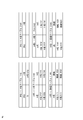
次に、図2を参照して、本実施形態におけるマッピングテーブルについて説明する。図2に示すマッピングテーブルは、変更不可能なデバイスが車両用デバイスとして使用される場合のマッピングテーブルの一例を示す図である。
Next, the mapping table in the present embodiment will be described with reference to FIG. The mapping table shown in FIG. 2 is a diagram illustrating an example of a mapping table when an unchangeable device is used as a vehicle device.
図2に示されるように、本実施形態におけるマッピングテーブルは、あるIRQ(割り込み情報に含まれる処理要求)がどのアプリケーションに該当するかを示すIRQからA名テーブル1142、3142と、それぞれのアプリケーションがどのハイパーバイザによって制御されているかを示すA名からH名テーブル1143、3143と、それぞれのハイパーバイザをアクセスするための経路を示すH名から接続テーブル1144、3144とを含む。これらのマッピングテーブルは、各車両制御装置に実装されるハイパーバイザ層が有する割り込み転送部に格納されてもよい。
As shown in FIG. 2, the mapping table in the present embodiment includes an IRQ indicating which application a certain IRQ (processing request included in interrupt information) corresponds to A name tables 1142 and 3142, and each application includes The A name to H name tables 1143 and 3143 indicating which hypervisor is controlled, and the H name to connection tables 1144 and 3144 indicating paths for accessing the respective hypervisors are included. These mapping tables may be stored in an interrupt transfer unit included in a hypervisor layer mounted on each vehicle control device.
例えば、マッピングテーブル1142、1143、及び1144は図3に示す車両制御装置1300に格納され、マッピングテーブル3142、3143、及び3144は車両制御装置3300に格納されてもよい(例示せず)。これにより、車両用デバイスからの割り込み信号が発生すると、割り込み転送部はこれらのマッピングテーブルを参照することで、当該割り込みを転送すべき送信先を特定することができる。
For example, the mapping tables 1142, 1143, and 1144 may be stored in the vehicle control device 1300 shown in FIG. 3, and the mapping tables 3142, 3143, and 3144 may be stored in the vehicle control device 3300 (not shown). Thus, when an interrupt signal is generated from the vehicular device, the interrupt transfer unit can specify a transmission destination to which the interrupt is transferred by referring to these mapping tables.
例えば、一例として、車両用デバイスからの割り込み信号が発生すると、割り込み転送部は、まず、IRQからA名テーブル1142を参照し、当該割り込みが対象とするアプリケーション(例えば、A名1212に該当するアプリケーション)を特定する。アプリケーションを特定した後、割り込み転送部は、A名からH名テーブル1143を参照し、特定したアプリケーションが実装されているハイパーバイザを特定する(例えば、H名1141に該当するハイパーバイザ)。
For example, when an interrupt signal from a vehicle device is generated as an example, the interrupt transfer unit first refers to the A name table 1142 from the IRQ, and applies to the application targeted by the interrupt (for example, an application corresponding to the A name 1212). ). After identifying the application, the interrupt transfer unit refers to the A name to the H name table 1143 to identify the hypervisor on which the identified application is mounted (for example, a hypervisor corresponding to the H name 1141).
ハイパーバイザを特定した後、割り込み転送部は、H名から接続テーブル1144を参照し、特定したハイパーバイザをアクセスするための接続(例えば、接続1031)を特定する。これにより、割り込み転送部は、ハイパーバイザを介して、発生した割り込み信号を、割り込み信号が該当するアプリケーションに転送することができる。
After identifying the hypervisor, the interrupt transfer unit refers to the connection table 1144 from the H name and identifies a connection (for example, connection 1031) for accessing the identified hypervisor. Thus, the interrupt transfer unit can transfer the generated interrupt signal to the application to which the interrupt signal corresponds via the hypervisor.
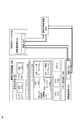
次に、図3を参照して、本発明に係るデータ処理システムについて説明する。図3は、本発明の第1の実施形態おける変更不可能な車両用デバイスからの割り込み信号をアプリケーションに転送するためのデータ処理システムを示す図である。
Next, the data processing system according to the present invention will be described with reference to FIG. FIG. 3 is a diagram showing a data processing system for transferring an interrupt signal from an unchangeable vehicle device according to the first embodiment of the present invention to an application.
本実施形態に係るデータ処理システムは、図3に示されるように、車両制御装置1300と、車両用デバイス2300と、車両制御装置3300とを含む。上述したように、車両制御装置1300、3300は自動車における様々なシステムを電子回路を用いて総合的に制御する装置である。また、車両用デバイス2300は、カメラ、温度計、車速センサ、空気圧センサ等の予め定めた機能を実施するための装置である。
The data processing system according to the present embodiment includes a vehicle control device 1300, a vehicle device 2300, and a vehicle control device 3300 as shown in FIG. As described above, the vehicle control devices 1300 and 3300 are devices that comprehensively control various systems in an automobile using electronic circuits. The vehicle device 2300 is an apparatus for performing predetermined functions such as a camera, a thermometer, a vehicle speed sensor, and an air pressure sensor.
また、車両制御装置はCPU1010及びCPU1020とを含む。図3には、二つのCPUを含む車両制御装置が一例として示されているが、本発明では、CPUの数は限定されるものではなく、CPUをn個含む構成であってもよい。
Also, the vehicle control device includes a CPU 1010 and a CPU 1020. Although FIG. 3 shows a vehicle control apparatus including two CPUs as an example, the number of CPUs is not limited in the present invention, and a configuration including n CPUs may be used.
また、車両制御装置1300は、車両用デバイス2300や車両制御装置3300の外部装置に相互的に接続されてもよく、外部装置との通信を行うための情報通信部1030を含んでもよい。この情報通信部1030は、自動車ネットワークにおける他の装置とのデータやり取りを行うものであり、接続1031を含む。この接続1031とは、外部装置とデータを入出力するためのIOインターフェースである。
Further, the vehicle control device 1300 may be mutually connected to an external device of the vehicle device 2300 or the vehicle control device 3300, and may include an information communication unit 1030 for performing communication with the external device. The information communication unit 1030 exchanges data with other devices in the automobile network, and includes a connection 1031. The connection 1031 is an IO interface for inputting / outputting data to / from an external device.
また、接続1031の「1031」とは、車両制御装置1300までのネットワーク経路を一意に識別する第4の識別子として機能する。なお、図3では、車両制御装置1300、車両用デバイス2300、及び車両制御装置3300のそれぞれがお互いに相互的に接続されている構成を示しているが、車両用デバイス2300と車両制御装置3300がお互いに接続されていない構成や、車両制御装置1300と車両用デバイス2300がお互いに接続されていない構成も可能である。
Further, “1031” of the connection 1031 functions as a fourth identifier for uniquely identifying the network route to the vehicle control device 1300. FIG. 3 shows a configuration in which the vehicle control device 1300, the vehicle device 2300, and the vehicle control device 3300 are connected to each other, but the vehicle device 2300 and the vehicle control device 3300 are connected to each other. A configuration in which the vehicle control device 1300 and the vehicle device 2300 are not connected to each other is also possible.
車両制御装置1300は、割り込み転送部1140を含むハイパーバイザ1100を有する。割り込み転送部1140は、上述したように、IRQからA名テーブル1142と、A名からH名テーブル1143と、H名から接続テーブル1144とを含み、車両用デバイスから発生した割り込み信号を転送する演算部である。この演算部とは、論理演算や四則演算などの演算を行うソフトウエアモジュールであり、ハイパーバイザ1100のような仮想化管理部に含まれてもよい。ここでは、「含まれる」という表現は、演算部の機能が仮想化管理部によって処理されることを意味する。具体的には、演算部は仮想化管理部内に実装されていない場合であっても演算部が実質的に仮想化管理部によって制御されている場合、及び、演算部が仮想化管理部上に実装されており、仮想化管理部によって制御されている場合の両方の態様を含む。このように、演算部を仮想化管理部内に実装することにより、割り込み情報を転送する処理をハイパーバイザ層において行うことができ、割り込み転送に生じる遅延を最小化することが可能となる。
The vehicle control device 1300 includes a hypervisor 1100 that includes an interrupt transfer unit 1140. As described above, the interrupt transfer unit 1140 includes an IRQ to A name table 1142, an A name to H name table 1143, and an H name to connection table 1144, and transfers an interrupt signal generated from a vehicle device. Part. The arithmetic unit is a software module that performs arithmetic operations such as logical operations and four arithmetic operations, and may be included in a virtualization management unit such as the hypervisor 1100. Here, the expression “included” means that the function of the calculation unit is processed by the virtualization management unit. Specifically, even when the calculation unit is not implemented in the virtualization management unit, the calculation unit is substantially controlled by the virtualization management unit, and the calculation unit is on the virtualization management unit. It includes both aspects when implemented and controlled by the virtualization manager. As described above, by mounting the arithmetic unit in the virtualization management unit, the process of transferring interrupt information can be performed in the hypervisor layer, and the delay occurring in the interrupt transfer can be minimized.
ハイパーバイザ1100は、CPU1010、CPU1020、及びメモリ1040等のリソースを用いて、仮想化環境1200を生成する。仮想化環境1200とは、車両制御装置1300の物理リソースを抽象化し、仮想機械やアプリケーションをお互いに独立した状態で実行させるための論理空間である。仮想化環境1200内では、WindowsやLinux等のオペレーティングシステムがスーパーバイザ1210、1220として実装される。それぞれのスーパーバイザ1210、1220の上では、アプリ1211及びアプリ1222が実装される。上述したように、これらのアプリ1211、1222とは、車両用デバイス2300が取得した生データを処理するプログラムであってもよい。
The hypervisor 1100 generates a virtual environment 1200 using resources such as the CPU 1010, the CPU 1020, and the memory 1040. The virtual environment 1200 is a logical space for abstracting physical resources of the vehicle control device 1300 and executing virtual machines and applications independently of each other. In the virtual environment 1200, an operating system such as Windows or Linux is installed as the supervisors 1210 and 1220. On each of the supervisors 1210 and 1220, an application 1211 and an application 1222 are installed. As described above, these applications 1211, 1222 may be programs that process raw data acquired by the vehicle device 2300.
また、それぞれのアプリ1211、1222は、お互いに独立した状態で同時に稼働するように構成されてもよい。更に、図3に示されるように、各アプリ1211、1222は、それぞれがネットワークで一意に識別されるためのA名に対応付けられている。例えば、アプリ1211はA名1212に対応付けられており、アプリ1222はA名1222に対応付られている。上述したように、これらのA名は、割り込み転送部1140のマッピングテーブルに格納され、割り込み信号を転送すべきハイパーバイザ及びアプリケーションを特定するために用いられる。
Further, the respective applications 1211, 1222 may be configured to operate simultaneously in an independent state. Further, as shown in FIG. 3, each of the applications 1211, 1222 is associated with an A name for uniquely identifying each of the networks. For example, the application 1211 is associated with the A name 1212, and the application 1222 is associated with the A name 1222. As described above, these A names are stored in the mapping table of the interrupt transfer unit 1140 and are used to specify the hypervisor and application to which the interrupt signal should be transferred.
上述したように、車両用デバイス2300は、カメラ、温度計、車速センサ、空気圧センサ等の予め定めた機能を実施するための専用装置である。図3に示されるように、車両用デバイス2300は情報通信部2030を含む。この情報通信部2030は、車両制御装置1300の情報通信部1030と同様に、自動車ネットワークにおける他の装置とのデータやり取りを行うものであり、接続2031を含む。この接続2031とは、外部装置とデータを入出力するためのIOインターフェースである。
As described above, the vehicle device 2300 is a dedicated device for performing predetermined functions such as a camera, a thermometer, a vehicle speed sensor, and an air pressure sensor. As shown in FIG. 3, the vehicular device 2300 includes an information communication unit 2030. Similar to the information communication unit 1030 of the vehicle control device 1300, the information communication unit 2030 performs data exchange with other devices in the automobile network, and includes a connection 2031. The connection 2031 is an IO interface for inputting / outputting data to / from an external device.
また、接続2031の「2031」とは、車両制御装置2300を一意に識別する第4の識別子として機能する。本実施形態では、車両用デバイス2300は、プログラム可能なインタフェースを有しない変更不可能なデバイスであるため、生データを取得し、車両制御装置に送信する機能だけを有する。ただし、本発明はこれに限定されず、車両用デバイス2300は他の機能を有する構成であってもよい。
Also, “2031” of the connection 2031 functions as a fourth identifier for uniquely identifying the vehicle control device 2300. In the present embodiment, the vehicular device 2300 is a non-changeable device that does not have a programmable interface, and thus has only a function of acquiring raw data and transmitting it to the vehicle control apparatus. However, the present invention is not limited to this, and the vehicular device 2300 may have another function.
上述したように、車両制御装置3300は、自動車における様々なシステムを電子回路を用いて総合的に制御する装置である。この車両制御装置3300の構造や機能は、車両制御装置1300と実質的に同様であるため、同様の構成要素について、詳細な説明を省略する。車両制御装置3300は、車両制御装置1300と同様に、CPUやメモリ等の物理リソース、ハイパーバイザ、及び仮想化環境を含む。また、車両制御装置3300のハイパーバイザやハイパーバイザ上で稼働するアプリケーションは、車両制御装置1300と同様に、第2の識別子であるH名および第3の識別子であるA名で識別される。
As described above, the vehicle control device 3300 is a device that comprehensively controls various systems in an automobile using electronic circuits. Since the structure and function of the vehicle control device 3300 are substantially the same as those of the vehicle control device 1300, detailed description of the same components will be omitted. Similar to the vehicle control device 1300, the vehicle control device 3300 includes physical resources such as a CPU and a memory, a hypervisor, and a virtual environment. Similarly to the vehicle control device 1300, the hypervisor of the vehicle control device 3300 and the application running on the hypervisor are identified by the H name as the second identifier and the A name as the third identifier.
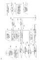
次に、図4を参照して、割り込み信号を転送することでアプリケーションと車両用デバイスとの通信を維持する処理について説明する。図4は、本発明の第1の実施形態における変更不可能な車両用デバイスからの割り込み信号をアプリケーションに転送する動作を示すフローチャート図である。
なお、以下の説明では、「#」というマークは、対象の装置・機能部を示す意味で使われており、任意の参照符号であってもよい。 Next, processing for maintaining communication between the application and the vehicle device by transferring an interrupt signal will be described with reference to FIG. FIG. 4 is a flowchart showing an operation of transferring an interrupt signal from an unchangeable vehicle device according to the first embodiment of the present invention to an application.
In the following description, the mark “#” is used to indicate a target device / function unit, and may be an arbitrary reference sign.
図4で示される割り込み転送処理は、あるアプリケーションが1つのハイパーバイザから、別の車両制御装置のハイパーバイザに移行された際に行われる。一例として、本処理は、カメラ(例えば、図3に示す車両用デバイス2300)が取得した映像データを解析するアプリケーション(例えば、図3に示すアプリ1211)が元の車両制御装置のハイパーバイザ(例えば、図3に示す車両制御装置3300のハイパーバイザ)から、別の車両制御装置のハイパーバイザ(例えば、図3に示す車両制御装置1300のハイパーバイザ1100)に移行された場合に適用されてもよい。このアプリケーション移行は、全体のシステムリソースの使用効率の向上、顧客向けのQoS(Quality of Service)改善等の理由で行われてもよい。
The interrupt transfer process shown in FIG. 4 is performed when an application is transferred from one hypervisor to another hypervisor of the vehicle control device. As an example, this processing is performed when an application (for example, the application 1211 illustrated in FIG. 3) that analyzes video data acquired by a camera (for example, the vehicle device 2300 illustrated in FIG. 3) is a hypervisor (for example, the original vehicle control device). 3 may be applied to a case where the hypervisor of another vehicle control device (for example, the hypervisor 1100 of the vehicle control device 1300 shown in FIG. 3) is transferred from the hypervisor of the vehicle control device 3300 shown in FIG. . This application migration may be performed for reasons such as improving the use efficiency of the overall system resources and improving quality of service (QoS) for customers.
アプリケーション移行を行うための具体的な手順やアプリケーションの移行先は、自動車ネットワークのリソース使用率、アプリケーション可用性、ネットワーク負荷や時間等の制約に応じて適宜に決められてもよく、ここでは限定されない。本発明では、アプリケーションは同一のA名(すなわち、アプリケーションのA名が起動時から終了時まで変わらない)を有し、上述したマッピングテーブルが自動車ネットワークの各ハイパーバイザに格納されていればよい。
The specific procedure for application migration and the application migration destination may be determined as appropriate according to restrictions such as the resource usage rate of the automobile network, application availability, network load, and time, and are not limited here. In the present invention, the applications have the same A name (that is, the A name of the application does not change from the start time to the end time), and the mapping table described above may be stored in each hypervisor of the automobile network.
一例として、自動車ネットワーク起動時に、周知のアルゴリズム(例えば、path finding algorithm、loop-free routing algorithm、ideal link-state algorithm等)が、ネットワーク内でどのハイパーバイザが使用されているか、特定のH名を有するハイパーバイザにアクセスするためにどの経路を使えばよいかを各ハイパーバイザに通知し、マッピングテーブルを更新してもよい。このアルゴリズムを定期的(一定時間ごとに、アプリケーションが追加・削除・変更される度等)に実行することで、それぞれのハイパーバイザが有するマッピングテーブルを更新することができる。
As an example, when starting up an automobile network, a well-known algorithm (eg path finding algorithm, loop-free routing algorithm, ideal link-state algorithm, etc.) can be used to specify which hypervisor is used in the network. The hypervisor may be notified of which route should be used to access the hypervisor, and the mapping table may be updated. By executing this algorithm periodically (every time, an application is added / deleted / changed etc.), the mapping table of each hypervisor can be updated.
図4に示すように、ステップ4000では、車両用デバイス(例えば、図3に示す車両用デバイス2300)が割り込み情報を生成する。この割り込み情報とは、CPUに対して、現在の処理を中断して、指定した処理を強制的に実行させることを要求する信号である。例えば、車両用デバイスがカメラである場合、車両デバイスは映像を撮像した後、撮像した画像をアプリケーションに処理させるために、割り込み情報を生成してもよい。
As shown in FIG. 4, in step 4000, the vehicle device (for example, the vehicle device 2300 shown in FIG. 3) generates interrupt information. The interrupt information is a signal that requests the CPU to interrupt the current process and forcibly execute the specified process. For example, when the vehicle device is a camera, the vehicle device may generate interrupt information in order to cause the application to process the captured image after capturing the video.
次に、ステップ4001では、車両用デバイスの情報通信部は接続#を介して、割り込み情報を所定の接続#に送信する。一例として、図3に示す車両用デバイス2300の情報通信部2030は、接続2031を介して、割り込み情報を車両制御装置3300の接続3031に送信してもよい。
Next, in step 4001, the information communication unit of the vehicle device transmits interrupt information to a predetermined connection # via connection #. As an example, the information communication unit 2030 of the vehicle device 2300 illustrated in FIG. 3 may transmit interrupt information to the connection 3031 of the vehicle control device 3300 via the connection 2031.
次に、ステップ4002では、接続#は車両用デバイスからの割り込み情報を受信する。
Next, in step 4002, connection # receives interrupt information from the vehicle device.
次に、ステップ4003では、接続#を有する情報通信部は、受信した割り込み情報を同一の車両制御装置内の割り込み転送部に送信する。
Next, in step 4003, the information communication unit having the connection # transmits the received interrupt information to the interrupt transfer unit in the same vehicle control device.
次に、ステップ4004では、割り込み転送部は、受信した割り込み情報が送信先のハイパーバイザを指定するH名メタデータに対応付けられているか否かを判断する。受信した割り込み情報は、送信先のハイパーバイザを指定するH名メタデータに対応付られている場合には、本処理はステップ4005に進行する。受信した割り込み情報は、送信先のハイパーバイザを指定するH名メタデータに対応付けられていない場合には、本処理はステップ4009に進行する。
Next, in step 4004, the interrupt transfer unit determines whether or not the received interrupt information is associated with H name metadata designating the destination hypervisor. If the received interrupt information is associated with H name metadata designating the destination hypervisor, the process proceeds to step 4005. If the received interrupt information is not associated with the H name metadata specifying the destination hypervisor, the process proceeds to step 4009.
受信した割り込み情報は、送信先のハイパーバイザを指定するH名メタデータに対応付られていない場合には、次にステップ4009では、割り込み転送部は受信した割り込み情報からIRQの情報を読み出す。
If the received interrupt information is not associated with the H name metadata designating the destination hypervisor, in step 4009, the interrupt transfer unit reads IRQ information from the received interrupt information.
次に、ステップ4010では、割り込み転送部は、ステップ4009で読み出したIRQ情報を用いて、IRQからA名テーブル#を参照し、当該IRQに対応するA名を検索する。
Next, in step 4010, the interrupt transfer unit searches the A name corresponding to the IRQ by referring to the A name table # from the IRQ using the IRQ information read in step 4009.
次に、ステップ4011では、割り込み転送部は、読み出したIRQに対応するA名がIRQからA名テーブル#に存在するかを判定する。一例としては、割り込み転送部は、ステップ4009で読み出したIRQ情報を用いて、図2に示すIRQからA名テーブル3142を参照し、当該IRQに対応するA名であるA名1212を取得する。受信したIRQに対応するA名がIRQからA名テーブル#にある場合には、本処理はステップ4012に進行し、ない場合には、本処理は終了する。
Next, in step 4011, the interrupt transfer unit determines whether an A name corresponding to the read IRQ exists from the IRQ in the A name table #. As an example, the interrupt transfer unit refers to the A name table 3142 from the IRQ shown in FIG. 2 using the IRQ information read in step 4009, and acquires the A name 1212 that is the A name corresponding to the IRQ. If the A name corresponding to the received IRQ is in the A name table # from the IRQ, the process proceeds to step 4012, and if not, the process ends.
次に、ステップ4012では、割り込み転送部は、取得したA名と、割り込み情報とを対応付ける。具体的には、割り込み転送部は、当該割り込み情報が処理すべきアプリケーションに該当するA名を指定するメタデータを割り込み情報に付す。一例として、割り込み転送部は、割り込み情報に、A名1212を指定するメタデータを対応付けてもよい。
Next, in step 4012, the interrupt transfer unit associates the acquired A name with the interrupt information. Specifically, the interrupt transfer unit attaches metadata specifying the A name corresponding to the application to be processed by the interrupt information to the interrupt information. As an example, the interrupt transfer unit may associate the metadata specifying the A name 1212 with the interrupt information.
次に、ステップ4013では、ステップ4011で取得したA名に該当するアプリケーションがどのハイパーバイザ上に稼働しているかを判定するために、割り込み転送部は、取得したA名を用いて、A名からH名テーブル#を参照し、当該A名に対応するH名(すなわち、ハイパーバイザ)を検索する。
Next, in step 4013, in order to determine on which hypervisor the application corresponding to the A name acquired in step 4011 is running, the interrupt transfer unit uses the acquired A name to start from the A name. With reference to the H name table #, the H name corresponding to the A name (that is, the hypervisor) is searched.
次に、ステップ4014では、割り込み転送部は、取得したA名に対応するH名がA名からH名テーブル#に存在するかを判定する。一例としては、割り込み転送部は、ステップ
4011で読み出したIRQ情報を用いて、図2に示すA名からH名テーブル3144を参照し、当該A名1212に対応するH名であるH名1141を取得する。受信したA名に対応するH名がA名からH名テーブル#にある場合には、本処理はステップ4015に進行し、ない場合には、本処理は終了する。 Next, instep 4014, the interrupt transfer unit determines whether the H name corresponding to the acquired A name exists from the A name to the H name table #. As an example, the interrupt transfer unit refers to the H name table 3144 from the A name shown in FIG. 2 using the IRQ information read in step 4011, and selects the H name 1141 that is the H name corresponding to the A name 1212. get. If the H name corresponding to the received A name is in the A name to H name table #, the process proceeds to step 4015, and if not, the process ends.
4011で読み出したIRQ情報を用いて、図2に示すA名からH名テーブル3144を参照し、当該A名1212に対応するH名であるH名1141を取得する。受信したA名に対応するH名がA名からH名テーブル#にある場合には、本処理はステップ4015に進行し、ない場合には、本処理は終了する。 Next, in
次に、ステップ4015では、割り込み転送部は、取得したH名と、割り込み情報とを対応付ける。具体的には、割り込み転送部は、当該割り込み情報が処理すべきアプリケーションを含むハイパーバイザに該当するH名を指定するメタデータを割り込み情報に付す。一例として、割り込み転送部は、割り込み情報に、H名1141を指定するメタデータを対応付けてもよい。
Next, in Step 4015, the interrupt transfer unit associates the acquired H name with the interrupt information. Specifically, the interrupt transfer unit attaches metadata specifying the H name corresponding to the hypervisor including the application to be processed by the interrupt information to the interrupt information. As an example, the interrupt transfer unit may associate the metadata specifying the H name 1141 with the interrupt information.
次に、A名とH名を割り込み情報に対応付けた後、本処理はステップ4005に戻る。ステップ4005では、割り込み転送部は、割り込み情報からH名(ステップ4015で対応付けたH名)を抽出する。一例として、割り込み転送部は、割り込み情報からH名1141を抽出してもよい。
Next, after the A name and the H name are associated with the interrupt information, the process returns to step 4005. In step 4005, the interrupt transfer unit extracts the H name (H name associated in step 4015) from the interrupt information. As an example, the interrupt transfer unit may extract the H name 1141 from the interrupt information.
次に、ステップ4006では、割り込み転送部は、抽出したH名を用いて、割り込み情報を受信したハイパーバイザがH名に指定されているハイパーバイザと同一のハイパーバイザであるか(つまり、送信先のアプリケーションが、割り込み情報を受信したハイパーバイザと同一の装置内で実装されているか)を判定する。割り込み情報を受信したハイパーバイザは、対応付られているH名に指定されているハイパーバイザと同一のハイパーバイザである場合(すなわち、割り込み情報を受信したハイパーバイザが送信先のハイパーバイザであるため、別の制御装置に転送する必要はない)には、本処理は、ステップ4007に進行し、そうでない場合には、本処理はステップ4016に進行する。
In step 4006, the interrupt transfer unit uses the extracted H name to determine whether the hypervisor that received the interrupt information is the same hypervisor as the hypervisor specified as the H name (that is, the transmission destination). Is installed in the same device as the hypervisor that received the interrupt information). The hypervisor that has received the interrupt information is the same hypervisor as the hypervisor specified for the associated H name (that is, the hypervisor that has received the interrupt information is the destination hypervisor) The process proceeds to step 4007, otherwise the process proceeds to step 4016.
割り込み情報を受信したハイパーバイザは、対応付られているH名に指定されているハイパーバイザと同一のハイパーバイザである場合、ステップ4007では、割り込み転送部は、ステップ4012で割り込み情報に対応付けたA名を割り込み情報から抽出する。一例として、割り込み転送部は、A名1212を割り込み情報から抽出してもよい。
When the hypervisor that has received the interrupt information is the same hypervisor as the hypervisor specified in the associated H name, in step 4007, the interrupt transfer unit associates the interrupt information with the interrupt information in step 4012. Extract A name from interrupt information. As an example, the interrupt transfer unit may extract the A name 1212 from the interrupt information.
次に、ステップ4015では、割り込み転送部は、受信した割り込み情報を、抽出したA名を持つアプリケーションに送信する。なお、ここでは、割り込み情報を受信したハイパーバイザは、H名で指定されているハイパーバイザと同一であるため、抽出したA名を持つアプリケーションが当該ハイパーバイザと同一の車両制御装置であり、H名から接続テーブルを参照する必要はない。
Next, in Step 4015, the interrupt transfer unit transmits the received interrupt information to the application having the extracted A name. Here, since the hypervisor that received the interrupt information is the same as the hypervisor specified by the H name, the application having the extracted A name is the same vehicle control device as the hypervisor, and the H There is no need to refer to the connection table by name.
ステップ4006において、割り込み情報を受信したハイパーバイザはH名に指定されているハイパーバイザではないと判定された場合、次に、ステップ4016では、割り込み転送部は、抽出したH名を用いて、H名から接続テーブル#を参照し、当該H名に対応する接続#を検索する。
If it is determined in step 4006 that the hypervisor that has received the interrupt information is not the hypervisor designated by the H name, then in step 4016, the interrupt transfer unit uses the extracted H name to By referring to the connection table # from the name, the connection # corresponding to the H name is searched.
次に、ステップ4017では、割り込み転送部は、抽出したH名に対応する接続#がH名から接続テーブル#に存在するか否かを判定する。一例としては、割り込み転送部は、ステップ4005で抽出したH名1141を用いて、図2に示すH名から接続テーブル3143を参照し、当該H名に対応する接続#である接続1031を取得する。受信したH名に対応する接続#名がH名から接続テーブル#にある場合には、本処理はステップ4018に進行し、ない場合には、本処理は終了する。
Next, in step 4017, the interrupt transfer unit determines whether or not the connection # corresponding to the extracted H name exists in the connection table # from the H name. As an example, the interrupt transfer unit refers to the connection table 3143 from the H name shown in FIG. 2 using the H name 1141 extracted in step 4005, and acquires the connection 1031 which is the connection # corresponding to the H name. . If the connection # name corresponding to the received H name is in the connection table # from the H name, the process proceeds to step 4018, and if not, the process ends.
次に、ステップ4018では、割り込み転送部は、情報通信部#を用いて、ステップ4017で取得した接続#に割り込み情報を送信する。一例として、割り込み転送部は、車両制御装置3300の接続3031(図3に例示せず)を介して、図3に示す割り込み情報を車両制御装置1300の接続1031に送信する。
Next, in step 4018, the interrupt transfer unit transmits the interrupt information to the connection # acquired in step 4017 using the information communication unit #. As an example, the interrupt transfer unit transmits the interrupt information illustrated in FIG. 3 to the connection 1031 of the vehicle control device 1300 via the connection 3031 (not illustrated in FIG. 3) of the vehicle control device 3300.
次に、ステップ4019では、送信先の車両制御装置の情報通信部は、接続#を介してステップ4018で送信された割り込み情報を受信し、同一の車両制御装置内の割り込み転送部に送信する。一例として、車両制御装置1300の情報通信部1030は、接続1031を介して、受信した割り込み情報を割り込み転送部1140に送信する。次に、割り込み情報を受信した割り込み転送部は、上述したステップ4003からの処理を行うことで、割り込み情報に対応付けられたH名及びA名を用いて、割り込み情報を送信すべきアプリケーションに転送することができる。
Next, in step 4019, the information communication unit of the destination vehicle control device receives the interrupt information transmitted in step 4018 via connection # and transmits it to the interrupt transfer unit in the same vehicle control device. As an example, the information communication unit 1030 of the vehicle control device 1300 transmits the received interrupt information to the interrupt transfer unit 1140 via the connection 1031. Next, the interrupt transfer unit that has received the interrupt information transfers the interrupt information to the application to be transmitted by using the H name and the A name associated with the interrupt information by performing the processing from step 4003 described above. can do.
このように、上述した割り込み転送部及びマッピングテーブルを用いることで、アプリケーションが、一つの制御装置から別の制御装置へと移行されても、車両用デバイスからの割り込み信号を転送させることによって、割り込み信号を発生させた車両用デバイスと当該車両用デバイスを管理するアプリケーションの通信が中断されない。
(第2の実施形態) As described above, by using the interrupt transfer unit and the mapping table described above, even if the application is transferred from one control device to another control device, the interrupt signal is transferred from the vehicle device, thereby interrupting the device. Communication between the vehicle device that generated the signal and the application that manages the vehicle device is not interrupted.
(Second Embodiment)
次に、図5~7を参照して、第2の実施形態におけるマッピングテーブルについて説明する。
Next, the mapping table in the second embodiment will be described with reference to FIGS.
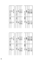
図5に示すマッピングテーブルは、変更可能なデバイスが車両用デバイスとして使用される場合のマッピングテーブルの一例を示す図である。
The mapping table shown in FIG. 5 is a diagram illustrating an example of a mapping table when a changeable device is used as a vehicle device.
図5に示されるように、本実施形態におけるマッピングテーブルは、あるIRQがどのアプリケーションに該当するかを示すIRQからA名テーブル1152、2152と、それぞれのアプリケーションがどのハイパーバイザによって制御されているかを示すA名からH名テーブル1153、2153と、それぞれのハイパーバイザをアクセスするための接続(すなわち、経路)を示すH名から接続テーブル1154、2154とを含む。これらのマッピングテーブルは、各車両制御装置に実装されるハイパーバイザ層が有する割り込み転送部に格納されてもよい。
例えば、マッピングテーブル1152、1153、及び1154は図6に示す車両制御装置1300に格納され、マッピングテーブル2152、2153、及び2154は車両制御装置3300に格納されてもよい(例示せず)。これにより、車両用デバイスからの割り込み信号が発生すると、割り込み転送部はこれらのマッピングテーブルを参照することで、当該割り込みを転送すべき送信先を特定することができる。 As shown in FIG. 5, the mapping table in the present embodiment includes ARQ tables 1152 and 2152 indicating which application a certain IRQ corresponds to, and which hypervisor controls each application. A name to H name tables 1153 and 2153, and connection names 1154 and 2154 from H names indicating connections (ie, routes) for accessing the respective hypervisors are included. These mapping tables may be stored in an interrupt transfer unit included in a hypervisor layer mounted on each vehicle control device.
For example, the mapping tables 1152, 1153, and 1154 may be stored in the vehicle control device 1300 shown in FIG. 6, and the mapping tables 2152, 2153, and 2154 may be stored in the vehicle control device 3300 (not shown). Thus, when an interrupt signal is generated from the vehicular device, the interrupt transfer unit can specify a transmission destination to which the interrupt is transferred by referring to these mapping tables.
後述するように、本実施形態に係るデータ処理システム(図6参照)は、割り込み情報転送処理の一部を担う変更可能な車両用デバイスを備えているため、本実施形態におけるマッピングテーブルの構成は、実施形態1に係るマッピングテーブルと異なる。具体的には、本実施形態におけるマッピングテーブルは、変更可能な車両用デバイスを識別するH名(例えば、H名2141)及び変更可能な車両用デバイスの入出力インターフェースとなる接続2031を有する点において、実施形態1に係るマッピングテーブルと異なる。このようなマッピングテーブル構成を用いることで、変更可能車両用デバイスは、割り込み情報転送処理の一部を担うことができ、実施形態1に係るデータ処理システムより更に効率よく行うことができる。
As will be described later, the data processing system according to the present embodiment (see FIG. 6) includes a changeable vehicle device that is responsible for part of the interrupt information transfer process. This is different from the mapping table according to the first embodiment. Specifically, the mapping table in the present embodiment includes an H name (for example, H name 2141) for identifying a changeable vehicle device and a connection 2031 that is an input / output interface of the changeable vehicle device. This is different from the mapping table according to the first embodiment. By using such a mapping table configuration, the changeable vehicle device can take part of the interrupt information transfer process, and can be performed more efficiently than the data processing system according to the first embodiment.
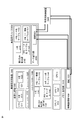
次に、図6を参照して、本発明に係るデータ処理システムについて説明する。図6は、本発明の第2の実施形態における変更可能な車両用デバイスからの割り込み信号をアプリケーションに転送するためのデータ処理システムを示す図である。
Next, a data processing system according to the present invention will be described with reference to FIG. FIG. 6 is a diagram illustrating a data processing system for transferring an interrupt signal from a changeable vehicle device according to the second embodiment of the present invention to an application.
本実施形態に係るデータ処理システムは、図6に示されるように、車両制御装置1300と、車両用デバイス2500と、車両制御装置3300とを含む。上述したように、車両制御装置1300、3300は自動車における様々なシステムを電子回路を用いて総合的に制御する装置である。また、車両用デバイス2500は、カメラ、温度計、車速センサ、空気圧センサ等の予め定めた機能を実施するための専用装置である。
The data processing system according to the present embodiment includes a vehicle control device 1300, a vehicle device 2500, and a vehicle control device 3300 as shown in FIG. As described above, the vehicle control devices 1300 and 3300 are devices that comprehensively control various systems in an automobile using electronic circuits. The vehicle device 2500 is a dedicated device for performing predetermined functions such as a camera, a thermometer, a vehicle speed sensor, and an air pressure sensor.
第2の実施形態に係るデータ処理システムは、変更不可能な車両用デバイス2300の代わりに、変更可能な車両用デバイス2500を有する点において、第2の実施形態に係るデータ処理システムと異なる。具体的には、車両用デバイス2500は、単に生データを取得して送信する車両用デバイス2300と異なり、情報通信部2030及び接続2031に加えて、割り込み転送部2140、H名2141、IRQからA名テーブル2142、A名からH名テーブル2143、及び、H名から接続テーブル2144を含む。このように、変更可能な車両用デバイス2500は、割り込み転送処理の一部(すなわち、割り込み情報の送信先となるハイパーバイザを判定する処理)を行うことができるため、割り込み信号を転送する処理を、第1の実施形態に係るデータ処理システムより更に効率よく行うことができる。
The data processing system according to the second embodiment differs from the data processing system according to the second embodiment in that it has a changeable vehicle device 2500 instead of the changeable vehicle device 2300. Specifically, the vehicle device 2500 is different from the vehicle device 2300 that simply acquires and transmits raw data, in addition to the information communication unit 2030 and the connection 2031, the interrupt transfer unit 2140, the H name 2141, and the IRQ to A A name table 2142, an A name to an H name table 2143, and an H name to a connection table 2144 are included. In this way, the changeable vehicle device 2500 can perform a part of the interrupt transfer process (that is, a process of determining the hypervisor that is the transmission destination of the interrupt information). This can be performed more efficiently than the data processing system according to the first embodiment.
第2の実施形態に係るデータ処理システムの構成は、変更不可能な車両用デバイス2300の代わりに、変更可能な車両用デバイス2500を有する点以外では、第1の実施形態に係るデータ処理システムと同様である。そのため、第1の実施形態に係るデータ処理システムと実質的に同様である構成要素の説明はここで繰り返さない。
The configuration of the data processing system according to the second embodiment is the same as that of the data processing system according to the first embodiment, except that it has a changeable vehicle device 2500 instead of the changeable vehicle device 2300. It is the same. Therefore, description of components that are substantially the same as those of the data processing system according to the first embodiment will not be repeated here.
次に、図7を参照して、割り込み信号を転送することでアプリケーションと車両用デバイスの通信を維持する処理について説明する。図7は、本発明の一実施例における変更可能な車両用デバイス(例えば、図6に示す変更可能な車両用デバイス2500)からの割り込み信号をアプリケーションに転送する動作を示すフローチャート図である。図7に示されるフローチャートでは、割り込み情報の送信先となるハイパーバイザを判定する処理が(変更可能な)車両用デバイスによって行われる点において、図4に示される処理と異なる。このように、割り込み情報の送信先となるハイパーバイザを判定する処理を車両用デバイスによって行うことで、割り込み情報を送信先のハイパーバイザに届けるための時間を短縮し、CPUなどのリソースを節約する等の効果が得られる。
なお、以下の説明では、「#」というマークは、対象の装置・機能部を示す意味で使われており、任意の参照符号であってもよい。 Next, processing for maintaining communication between the application and the vehicle device by transferring an interrupt signal will be described with reference to FIG. FIG. 7 is a flowchart showing an operation of transferring an interrupt signal from a changeable vehicle device (for example, the changeable vehicle device 2500 shown in FIG. 6) to an application in an embodiment of the present invention. The flowchart shown in FIG. 7 is different from the process shown in FIG. 4 in that the process of determining the hypervisor that is the transmission destination of the interrupt information is performed by a (changeable) vehicle device. In this way, the process for determining the hypervisor that is the destination of the interrupt information is performed by the vehicle device, thereby reducing the time required to deliver the interrupt information to the destination hypervisor and saving resources such as the CPU. Etc. are obtained.
In the following description, the mark “#” is used to indicate a target device / function unit, and may be an arbitrary reference sign.
図7で示される割り込み転送処理は、あるアプリケーションが1つのハイパーバイザから、別の車両制御装置のハイパーバイザに移行された際に行われる。一例として、本処理は、カメラ(例えば、図6に示す車両用デバイス2500)が取得した映像データを解析するアプリケーション(例えば、図6に示すアプリ1211)が元の車両制御装置のハイパーバイザ(例えば、図6に示す車両制御装置3300のハイパーバイザ)から、別の車両制御装置のハイパーバイザ(例えば、図6に示す車両制御装置1300のハイパーバイザ1100)に移行された場合に適用されてもよい。このアプリケーション移行は、全体システムのリソースの使用効率の向上、顧客向けのQoS(Quality of Service)改善等の理由で行われてもよい。
The interrupt transfer process shown in FIG. 7 is performed when an application is transferred from one hypervisor to another vehicle controller hypervisor. As an example, this processing is performed when an application (for example, the application 1211 illustrated in FIG. 6) that analyzes video data acquired by a camera (for example, the vehicle device 2500 illustrated in FIG. 6) is a hypervisor (for example, the original vehicle control device). 6 may be applied to a case in which the hypervisor of another vehicle control device (for example, the hypervisor 1100 of the vehicle control device 1300 shown in FIG. 6) is transferred from the hypervisor of the vehicle control device 3300 shown in FIG. . This application migration may be performed for reasons such as improving the use efficiency of resources of the entire system and improving quality of service (QoS) for customers.
上述したように、アプリケーション移行を行うための具体的な手順やアプリケーションの移行先は、自動車ネットワークのリソース使用率、アプリケーション可用性、ネットワーク負荷や時間等の制約に応じて適宜に決められてもよく、ここでは限定されない。本発明では、アプリケーションは同一のA名(すなわち、アプリケーションのA名が起動時から終了時まで変わらない)を有し、上述したマッピングテーブルが自動車ネットワークの各ハイパーバイザに格納されていればよい。一例として、自動車ネットワーク起動時に、周知のアルゴリズム(例えば、path finding algorithm、loop-free routing algorithm、ideal link-state algorithm等)が、ネットワーク内でどのハイパーバイザが使用されているか、特定のH名を有するハイパーバイザにアクセスするためにどの経路を使えばよいかを各ハイパーバイザに通知し、マッピングテーブルを更新してもよい。このアルゴリズムを定期的(一定時間ごとに、アプリケーションが追加・削除・変更される度等)に実行することで、それぞれのハイパーバイザが有するマッピングテーブルを更新することができる。
As described above, the specific procedure for performing application migration and the application migration destination may be appropriately determined according to restrictions such as the resource usage rate of the automobile network, application availability, network load, and time, It is not limited here. In the present invention, the applications have the same A name (that is, the A name of the application does not change from the start time to the end time), and the mapping table described above may be stored in each hypervisor of the automobile network. As an example, when starting up an automobile network, a well-known algorithm (eg path finding algorithm, loop-free routing algorithm, ideal link-state algorithm, etc.) can be used to specify which hypervisor is used in the network. The hypervisor may be notified of which route should be used to access the hypervisor, and the mapping table may be updated. By executing this algorithm periodically (every time, an application is added / deleted / changed etc.), the mapping table of each hypervisor can be updated.
図7に示すように、ステップ5000では、車両用デバイス(例えば、図6に示す車両用デバイス2500)が割り込み情報を生成する。この割り込み情報とは、CPUに対して、現在の処理を中断して、指定した処理を強制的に実行させることを要求する信号である。例えば、車両用デバイスがカメラである場合、車両デバイスは映像を撮像した後、撮像した画像をアプリケーションに処理させるために、割り込み情報を生成してもよい。
As shown in FIG. 7, in step 5000, the vehicle device (for example, the vehicle device 2500 shown in FIG. 6) generates interrupt information. The interrupt information is a signal that requests the CPU to interrupt the current process and forcibly execute the specified process. For example, when the vehicle device is a camera, the vehicle device may generate interrupt information in order to cause the application to process the captured image after capturing the video.
次に、ステップ5001では、割り込み情報を生成した車両用デバイスは、当該車両用のデバイス内の割り込み転送部に送信する。一例として、図6に示す車両用デバイス2500は、割り込み情報を当該車両用デバイス2500の割り込み転送部2140に送信する。
Next, in step 5001, the vehicle device that generated the interrupt information transmits the interrupt information to the interrupt transfer unit in the vehicle device. As an example, the vehicle device 2500 illustrated in FIG. 6 transmits interrupt information to the interrupt transfer unit 2140 of the vehicle device 2500.
次に、ステップ5002では、割り込み情報を受信した割り込み転送部(例えば、図6に示す車両用デバイス2500の割り込み転送部2140)は、受信した割り込み情報が送信先のハイパーバイザを指定するH名メタデータに対応付けられているか否かを判定する。受信した割り込み情報は、送信先のハイパーバイザを指定するH名メタデータに対応付けられている場合には、本処理はステップ5003に進行する。受信した割り込み情報は、送信先のハイパーバイザを指定するH名メタデータに対応付けられていない場合には、本処理はステップ5007に進行する。
Next, in step 5002, the interrupt transfer unit that has received the interrupt information (for example, the interrupt transfer unit 2140 of the vehicle device 2500 shown in FIG. 6), the received name information that specifies the destination hypervisor. It is determined whether or not it is associated with data. If the received interrupt information is associated with H name metadata designating the destination hypervisor, the process proceeds to step 5003. If the received interrupt information is not associated with the H name metadata specifying the destination hypervisor, the process proceeds to step 5007.
受信した割り込み情報は、送信先のハイパーバイザを指定するH名メタデータに対応付けられていない場合には、次にステップ5007では、割り込み転送部は受信した割り込み情報からIRQの情報を読み出す。
If the received interrupt information is not associated with the H name metadata designating the destination hypervisor, then in step 5007, the interrupt transfer unit reads IRQ information from the received interrupt information.
次に、ステップ5008では、割り込み転送部は、ステップ5007で読み出したIRQ情報を用いて、IRQからA名テーブル#を参照し、当該IRQに対応するA名を検索する。
Next, in step 5008, the interrupt transfer unit refers to the A name table # from the IRQ using the IRQ information read in step 5007, and searches for the A name corresponding to the IRQ.
次に、ステップ5009では、割り込み転送部は、読み出したIRQに対応するA名がIRQからA名テーブル#に存在するかを判定する。一例としては、割り込み転送部は、ステップ5007で読み出したIRQ情報を用いて、図6に示すIRQからA名テーブル2152を参照し、当該IRQに対応するA名であるA名1222を取得する。受信したIRQに対応するA名がIRQからA名テーブル#にある場合には、本処理はステップ5010に進行し、受信したIRQに対応するA名がIRQからA名テーブル#にない場合には、本処理は終了する。
Next, in step 5009, the interrupt transfer unit determines whether an A name corresponding to the read IRQ exists from the IRQ in the A name table #. As an example, the interrupt transfer unit refers to the A name table 2152 from the IRQ shown in FIG. 6 using the IRQ information read in step 5007, and acquires the A name 1222 that is the A name corresponding to the IRQ. If the A name corresponding to the received IRQ is in the A name table # from the IRQ, the process proceeds to step 5010, and if the A name corresponding to the received IRQ is not in the A name table # from the IRQ. This process ends.
次に、ステップ5010では、割り込み転送部は、取得したA名と、割り込み情報とを対応付ける。具体的には、割り込み転送部は、当該割り込み情報が処理すべきアプリケーションに該当するA名を指定するメタデータを割り込み情報に付す。一例として、割り込み転送部2140は、割り込み情報に、A名1222を指定するメタデータを対応付けてもよい。
Next, in step 5010, the interrupt transfer unit associates the acquired A name with the interrupt information. Specifically, the interrupt transfer unit attaches metadata specifying the A name corresponding to the application to be processed by the interrupt information to the interrupt information. As an example, the interrupt transfer unit 2140 may associate the metadata specifying the A name 1222 with the interrupt information.
次に、ステップ5011では、ステップ5008で取得したA名に該当するアプリケーションがどのハイパーバイザ上に稼働しているかを判定するために、割り込み転送部は、取得したA名を用いて、A名からH名テーブル#を参照し、当該A名に対応するH名(すなわち、ハイパーバイザ)を検索する。
Next, in step 5011, in order to determine on which hypervisor the application corresponding to the A name acquired in step 5008 is running, the interrupt transfer unit uses the acquired A name to start from the A name. With reference to the H name table #, the H name corresponding to the A name (that is, the hypervisor) is searched.
次に、ステップ5012では、割り込み転送部は、取得したA名に対応するH名がA名からH名テーブル#に存在するかを判定する。一例としては、割り込み転送部2140は、ステップ5007で読み出したIRQ情報を用いて、図6に示すA名からH名テーブル2153を参照し、当該A名1222に対応するH名であるH名1141を取得する。受信したA名に対応するH名がA名からH名テーブル#にある場合には、本処理はステップ5013に進行し、ない場合には、本処理は終了する。
Next, in step 5012, the interrupt transfer unit determines whether the H name corresponding to the acquired A name exists from the A name to the H name table #. As an example, the interrupt transfer unit 2140 refers to the H name table 2153 from the A name shown in FIG. 6 using the IRQ information read in step 5007, and the H name 1141 that is the H name corresponding to the A name 1222 To get. If the H name corresponding to the received A name is in the A name to H name table #, the process proceeds to step 5013, and if not, the process ends.
次に、ステップ5013では、割り込み転送部は、取得したH名と、割り込み情報とを対応付ける。具体的には、割り込み転送部は、当該割り込み情報が処理すべきアプリケーションを含むハイパーバイザに該当するH名を指定するメタデータを割り込み情報に付す。一例として、割り込み転送部2140は、割り込み情報に、H名1141を指定するメタデータを対応付けてもよい。
Next, in step 5013, the interrupt transfer unit associates the acquired H name with the interrupt information. Specifically, the interrupt transfer unit attaches metadata specifying the H name corresponding to the hypervisor including the application to be processed by the interrupt information to the interrupt information. As an example, the interrupt transfer unit 2140 may associate the metadata specifying the H name 1141 with the interrupt information.
次に、本処理はステップ5002に戻り、受信した割り込み情報が送信先のハイパーバイザを指定するH名メタデータに対応付けられているか否かを判定する。今回の処理では、H名メタデータがステップ5013で割り込み情報に対応付けられたため、H名メタデータが対応付られていると判定され、本処理はステップ5003に進行する。
Next, the process returns to step 5002, and it is determined whether or not the received interrupt information is associated with H name metadata specifying the destination hypervisor. In this process, since the H name metadata is associated with the interrupt information in step 5013, it is determined that the H name metadata is associated, and the process proceeds to step 5003.
次に、ステップ5003では、割り込み転送部は、割り込み情報からH名(ステップ5013で対応付けたH名)を抽出する。一例として、割り込み転送部は、割り込み情報からH名1141を抽出してもよい。
Next, in step 5003, the interrupt transfer unit extracts the H name (H name associated in step 5013) from the interrupt information. As an example, the interrupt transfer unit may extract the H name 1141 from the interrupt information.
次に、ステップ5004では、割り込み転送部は、抽出したH名を用いて、割り込み情報を受信したハイパーバイザがH名に指定されているハイパーバイザと同一のハイパーバイザであるか(つまり、送信先のアプリケーションが、割り込み情報を受信したハイパーバイザと同一の装置内で実装されているか)を判定する。割り込み情報を受信したハイパーバイザは、対応付けられているH名に指定されているハイパーバイザと同一のハイパーバイザである場合(すなわち、割り込み情報を受信したハイパーバイザが送信先のハイパーバイザであるため、別の制御装置に転送する必要はない)には、本処理は、ステップ5005に進行し、そうでない場合には、本処理はステップ5014に進行する。
In step 5004, the interrupt transfer unit uses the extracted H name to determine whether the hypervisor that has received the interrupt information is the same hypervisor as the hypervisor specified as the H name (that is, the transmission destination). Is installed in the same device as the hypervisor that received the interrupt information). The hypervisor that received the interrupt information is the same hypervisor as the hypervisor specified for the associated H name (that is, the hypervisor that received the interrupt information is the destination hypervisor) The process proceeds to step 5005, otherwise the process proceeds to step 5014.
割り込み情報を受信したハイパーバイザが、対応付けられているH名に指定されているハイパーバイザと同一のハイパーバイザである場合、ステップ5005では、割り込み転送部は、ステップ5010で割り込み情報に対応付けたA名を割り込み情報から抽出する。一例として、割り込み転送部2140は、A名1222を割り込み情報から抽出してもよい。
When the hypervisor that has received the interrupt information is the same hypervisor as the hypervisor specified in the associated H name, in step 5005, the interrupt transfer unit associates the interrupt information with the interrupt information in step 5010. Extract A name from interrupt information. As an example, the interrupt transfer unit 2140 may extract the A name 1222 from the interrupt information.
次に、ステップ5006では、割り込み転送部は、受信した割り込み情報を、抽出したA名を持つアプリケーションに送信し、本処理は終了する。なお、ここでは、割り込み情報を受信したハイパーバイザがH名で指定されているハイパーバイザと同一であるため、抽出したA名を持つアプリケーションが当該ハイパーバイザと同一の車両制御装置であり、H名から接続テーブルを参照する必要はない。
Next, in step 5006, the interrupt transfer unit transmits the received interrupt information to the application having the extracted A name, and this process ends. Here, since the hypervisor that received the interrupt information is the same as the hypervisor specified by the H name, the application having the extracted A name is the same vehicle control device as the hypervisor, and the H name There is no need to refer to the connection table.
ステップ5004において、割り込み情報を受信したハイパーバイザはH名に指定されているハイパーバイザではないと判定された場合、次に本処理はステップ5014に進行する。ステップ5014では、割り込み転送部は、抽出したH名を用いて、H名から接続テーブル#を参照し、当該H名に対応する接続#を検索する。
If it is determined in step 5004 that the hypervisor that has received the interrupt information is not the hypervisor designated by the H name, the process proceeds to step 5014. In step 5014, using the extracted H name, the interrupt transfer unit refers to the connection table # from the H name and searches for a connection # corresponding to the H name.
次に、ステップ5015では、割り込み転送部は、抽出したH名に対応する接続#がH名から接続テーブル#に存在するか否かを判定する。一例としては、割り込み転送部2140は、ステップ5003で抽出したH名1141を用いて、図6に示すH名から接続テーブル2154を参照し、当該H名に対応する接続#である接続1031を取得する。受信したH名に対応する接続#名がH名から接続テーブル#にある場合には、本処理はステップ45016に進行し、ない場合には、本処理は終了する。
Next, in step 5015, the interrupt transfer unit determines whether or not the connection # corresponding to the extracted H name exists in the connection table # from the H name. As an example, the interrupt transfer unit 2140 uses the H name 1141 extracted in step 5003 to refer to the connection table 2154 from the H name shown in FIG. To do. If the connection # name corresponding to the received H name is in the connection table # from the H name, the process proceeds to step 45016, and if not, the process ends.
次に、ステップ5016では、割り込み転送部は、情報通信部#を用いて、ステップ5015で取得した送信先の車両制御装置の接続#に割り込み情報を送信する。一例として、割り込み転送部2140は接続2031を介して、図6に示す割り込み情報を車両制御装置1300の接続1031に送信する。
Next, in Step 5016, the interrupt transfer unit transmits the interrupt information to the connection # of the destination vehicle control apparatus acquired in Step 5015 using the information communication unit #. As an example, the interrupt transfer unit 2140 transmits the interrupt information illustrated in FIG. 6 to the connection 1031 of the vehicle control device 1300 via the connection 2031.
次に、ステップ5017では、送信先の車両制御装置の情報通信部は、接続#を介してステップ5016で送信された割り込み情報を受信し、同一の車両制御装置内の割り込み転送部に送信する。一例として、車両制御装置1300の情報通信部1030は、接続1031を介して、受信した割り込み情報を割り込み転送部1140に送信する。次に、割り込み情報を受信した割り込み転送部は、上述したステップ5002からの処理を行うことで、割り込み情報に対応付けられたH名及びA名を用いて、割り込み情報を送信すべきアプリケーションに転送することができる。
Next, in step 5017, the information communication unit of the destination vehicle control device receives the interrupt information transmitted in step 5016 via connection # and transmits it to the interrupt transfer unit in the same vehicle control device. As an example, the information communication unit 1030 of the vehicle control device 1300 transmits the received interrupt information to the interrupt transfer unit 1140 via the connection 1031. Next, the interrupt transfer unit that has received the interrupt information transfers the interrupt information to the application to be transmitted by using the H name and the A name associated with the interrupt information by performing the processing from step 5002 described above. can do.
このように、第2の実施形態に係るデータ処理システムは、変更可能な車両用デバイスを用いて割り込み転送処理を行うことで、割り込み信号が送信先の車両制御装置に届くまでの時間を短縮し、車両制御装置の処理負荷を削減できるため、第1の実施形態に係るデータ処理システムに比べて、割り込み転送処理を更に効率よく行うことが可能となる。
As described above, the data processing system according to the second embodiment shortens the time until the interrupt signal reaches the destination vehicle control device by performing the interrupt transfer process using the changeable vehicle device. Since the processing load of the vehicle control device can be reduced, interrupt transfer processing can be performed more efficiently than the data processing system according to the first embodiment.
次に、実施例1~4を用いて、本発明に係る割り込み転送を実装した具体例を説明する。
Next, a specific example in which the interrupt transfer according to the present invention is implemented will be described using the first to fourth embodiments.
実施例1は、上述した車両制御装置(例えば、図3に示す車両制御装置1300、3300)を、SoCとして半導体基盤に搭載し、PCIExpress等の通信媒体によって相互接続する。このような場合には、各SoC上には、ハイパーバイザ及び割り込み転送部が実装され、これらのSoCは情報通信部として機能するPCIExpress経由で、割り込み情報転送等のデータやり取りを行うことができる(すなわち、PCIExpressは図3における情報通信部1030として機能する)。
In the first embodiment, the above-described vehicle control device (for example, the vehicle control devices 1300 and 3300 shown in FIG. 3) is mounted on a semiconductor substrate as an SoC and interconnected by a communication medium such as PCI Express. In such a case, a hypervisor and an interrupt transfer unit are mounted on each SoC, and these SoCs can exchange data such as interrupt information transfer via PCI Express functioning as an information communication unit ( In other words, PCI Express functions as the information communication unit 1030 in FIG.
実施例2では、上述した車両制御装置(例えば、図3に示す車両制御装置1300、3
300)は、ECUとして自動車に搭載され、車載Ethernetによって他のデバイス(他のECU及びカメラやセンサ等の車両用デバイス)に相互接続される。このような場合には、各ECU上には、ハイパーバイザ及び割り込み転送部は実装され、車載Ethernetを介してお互いに割り込み情報を転送することができる。また、本実施例では、各ECUには複数のハイパーバイザが実装されてもよい。この場合には、ハイパーバイザごとに、割り込み転送のON・OFFを設定する構成であってもよい。 In the second embodiment, the above-described vehicle control device (for example, the vehicle control devices 1300 and 3 shown in FIG. 3).
300) is mounted on an automobile as an ECU, and is interconnected to other devices (other ECUs and devices for vehicles such as cameras and sensors) by in-vehicle Ethernet. In such a case, a hypervisor and an interrupt transfer unit are mounted on each ECU, and interrupt information can be transferred to each other via the in-vehicle Ethernet. In the present embodiment, a plurality of hypervisors may be mounted on each ECU. In this case, the configuration may be such that interrupt transfer ON / OFF is set for each hypervisor.
本実施例3では、上述した車両制御装置(例えば、図3に示す車両制御装置1300、3300)は、それぞれ異なる自動車に搭載される。これらの自動車は、LTEAdvancedや802.11等の無線通信で相互接続される。このような場合には、車両用デバイス(例えば、図3に示す車両用デバイス2300)は、1つの車両制御装置のみに接続される。
In the third embodiment, the above-described vehicle control devices (for example, the vehicle control devices 1300 and 3300 shown in FIG. 3) are installed in different automobiles. These automobiles are interconnected by wireless communication such as LTE Advanced and 802.11. In such a case, the vehicle device (for example, the vehicle device 2300 shown in FIG. 3) is connected to only one vehicle control device.
また、この場合には、それぞれの自動車に、ハイパーバイザや割り込み転送部が実装され、これらのハイパーバイザや割り込み転送部は、上述したLTEAdvancedや802.11等の無線通信を介して、割り込み情報を別の自動車に実装されているアプリケーションに転送することができる。これにより、アプリケーションは、元の自動車の車両用デバイスとの接続を維持しつつ、別の自動車に移行されてもよい。
In this case, a hypervisor and an interrupt transfer unit are mounted on each vehicle, and these hypervisors and interrupt transfer units send different interrupt information via wireless communication such as the above-described LTE Advanced and 802.11. It can be transferred to the application installed in the car. Thereby, the application may be transferred to another automobile while maintaining the connection with the vehicle device of the original automobile.
本実施例4では、上述した車両制御装置の1つ(例えば、図3に示す車両制御装置1300)は自動車に搭載され、1つまたは複数の車両用デバイス(例えば、図3に示す車両用デバイス2300)に接続される。そして、他の制御装置は、データセンターに設置され、インターネット等のネットワークを介して自動車に搭載されている車両制御装置に相互接続される。このような場合には、自動車に搭載されている制御装置のリソースが不足する場合には、自動車に実装されているアプリケーションがデータセンターに設置されている制御装置に移行され、自動車の割り込み転送部は車両用デバイスからの割り込み情報を、インターネットを介してデータセンターに設置される制御装置に転送することができる。これにより、アプリケーションは、元の自動車の車両用デバイスとの接続を維持しつつ、データセンターの制御装置のリソースを活用することができ、アプリケーションの性能を向上させる効果が得られる。
In the fourth embodiment, one of the vehicle control devices described above (for example, the vehicle control device 1300 shown in FIG. 3) is mounted on an automobile, and one or a plurality of vehicle devices (for example, the vehicle device shown in FIG. 3). 2300). The other control devices are installed in the data center and are interconnected to the vehicle control device mounted on the automobile via a network such as the Internet. In such a case, if the resources of the control device installed in the vehicle are insufficient, the application installed in the vehicle is transferred to the control device installed in the data center, and the interrupt transfer unit of the vehicle Can transfer interrupt information from a vehicle device to a control device installed in a data center via the Internet. Thereby, the application can utilize the resources of the control device of the data center while maintaining the connection with the vehicle device of the original automobile, and the effect of improving the performance of the application can be obtained.
以上、本発明のいくつかの実施例を説明してきたが、これらは、本発明の説明のための例示であって、本発明の範囲をこれらの実施例にのみ限定する趣旨ではない。本発明は、他の種々の形態でも実施する事が可能である。
Although several embodiments of the present invention have been described above, these are examples for explaining the present invention, and are not intended to limit the scope of the present invention only to these embodiments. The present invention can be implemented in various other forms.
105:車両用デバイス,110、120、130、140、150:車両制御装置,1100:ハイパーバイザ,1142、2152、3142:IRQからA名テーブル,1143、2153、3143:A名からH名テーブル,1144、2154、3144:H名から接続テーブル,1300、3300:車両制御装置,2300:変更不可能な車両用デバイス,2500:変更可能な車両用デバイス
105: Vehicle device, 110, 120, 130, 140, 150: Vehicle control device, 1100: Hypervisor, 1142, 2152, 3142: IRQ to A name table, 1143, 2153, 3143: A name to H name table, 1144, 2154, 3144: Connection table from H name, 1300, 3300: Vehicle control device, 2300: Unchangeable vehicle device, 2500: Changeable vehicle device
Claims (15)
- 車両用デバイスに接続可能な第1の車両制御装置であって、
前記第1の車両制御装置は、
複数の仮想化管理部、記憶部及び演算部とを備え、
アプリケーションソフトウエアが実装されており、
前記記憶部は、前記第1の車両制御装置に接続される車両用デバイスからの割り込み情報を一意に識別する第1の識別子と、前記第1の車両制御装置に実装される前記仮想化管理部を一意に識別する第2の識別子と、前記アプリケーションソフトウエアを一意に識別する第3の識別子と、を対応付けたマッピングテーブルを格納し、
前記演算部は、
前記第1の識別子を含む割り込み情報を前記車両用デバイスから受信した場合に、
前記マッピングテーブルに基づき、前記第1の車両制御装置における前記複数の仮想化管理部の中から、前記割り込み情報の転送先となる仮想化管理部を決定する、
ことを特徴とする車両制御装置。 A first vehicle control device connectable to a vehicle device,
The first vehicle control device includes:
A plurality of virtualization management units, a storage unit and a calculation unit,
Application software is implemented,
The storage unit includes a first identifier for uniquely identifying interrupt information from a vehicle device connected to the first vehicle control device, and the virtualization management unit implemented in the first vehicle control device. A mapping table that associates a second identifier for uniquely identifying the third identifier for uniquely identifying the application software;
The computing unit is
When the interrupt information including the first identifier is received from the vehicle device,
Based on the mapping table, a virtualization management unit that is a transfer destination of the interrupt information is determined from the plurality of virtualization management units in the first vehicle control device.
The vehicle control apparatus characterized by the above-mentioned. - 前記第1の車両制御装置において、
前記演算部が、前記仮想化管理部に含まれる、
ことを特徴とする請求項1に記載の車両制御装置。 In the first vehicle control device,
The calculation unit is included in the virtualization management unit,
The vehicle control device according to claim 1. - 前記複数の仮想化管理部は、それぞれ構成の異なる車両制御装置に含まれる、
ことを特徴とする請求項2に記載の車両制御装置。 The plurality of virtualization management units are included in vehicle control devices having different configurations.
The vehicle control device according to claim 2. - 前記第1の車両制御装置において、
前記記憶部に格納される前記マッピングテーブルは、割り込み情報を転送する際に使用するネットワーク経路を一意に識別する第4の識別子と、前記第2の識別子とを対応付けた情報を含む、
ことを特徴とする請求項3に記載の車両制御装置。 In the first vehicle control device,
The mapping table stored in the storage unit includes information in which a fourth identifier that uniquely identifies a network path used when transferring interrupt information is associated with the second identifier;
The vehicle control device according to claim 3. - 前記第1の車両制御装置に接続される車両用デバイスは、任意のプログラムが実施可能なデバイスである、
ことを特徴とする請求項1に記載の車両制御装置。 The vehicle device connected to the first vehicle control device is a device capable of executing an arbitrary program.
The vehicle control device according to claim 1. - 前記第1の車両制御装置及び第2の車両制御装置が自動車に搭載され、
前記第2の車両制御装置は、
第2の仮想化管理部を実装し、
前記第1の車両制御装置に実装される前記アプリケーションソフトウエアが前記第2の車両制御装置に移行された場合に、
前記第1の車両制御装置の前記演算部は、
前記車両用デバイスから、前記第1の識別子を含む割り込み情報を受信し、
前記第1の識別子を用いて、前記マッピングテーブルから、前記第2の車両制御装置の前記第2の仮想化管理部に対応する前記第2の識別子を抽出し、
前記第2の識別子を用いて、前記マッピングテーブルから、前記アプリケーションソフトウエアに対応する前記第3の識別子を抽出し、
前記第3の識別子を用いて、前記マッピングテーブルから、前記第2の車両制御装置までのネットワーク経路に対応する前記第4の識別子を抽出し、
前記割り込み情報を、前記第2の車両制御装置までの前記ネットワーク経路を介して送信する、
ことを特徴とする請求項4に記載の車両制御装置。 The first vehicle control device and the second vehicle control device are mounted on an automobile,
The second vehicle control device includes:
Implement the second virtualization manager,
When the application software implemented in the first vehicle control device is transferred to the second vehicle control device,
The calculation unit of the first vehicle control device includes:
Receiving interrupt information including the first identifier from the vehicle device;
Using the first identifier, the second identifier corresponding to the second virtualization management unit of the second vehicle control device is extracted from the mapping table,
Extracting the third identifier corresponding to the application software from the mapping table using the second identifier;
Using the third identifier, the fourth identifier corresponding to the network route to the second vehicle control device is extracted from the mapping table,
Transmitting the interrupt information via the network route to the second vehicle control device;
The vehicle control device according to claim 4. - 車両用デバイスに接続可能な第1の車両制御装置における割り込み情報管理方法であって、
前記第1の車両制御装置は、
複数の仮想化管理部、記憶部及び演算部とを備え、
アプリケーションソフトウエアが実装されており、
前記記憶部は、前記第1の車両制御装置に接続される車両用デバイスからの割り込み情報を一意に識別する第1の識別子と、前記第1の車両制御装置に実装される前記仮想化管理部を一意に識別する第2の識別子と、前記アプリケーションソフトウエアを一意に識別する第3の識別子と、を対応付けたマッピングテーブルを格納しており、
前記演算部が、
前記第1の識別子を含む割り込み情報を前記車両用デバイスから受信した場合に、
前記マッピングテーブルに基づき、前記第1の車両制御装置における前記複数の仮想化管理部の中から、前記割り込み情報の転送先となる仮想化管理部を前記演算部によって決定する工程、
を含む割り込み情報管理方法。 An interrupt information management method in a first vehicle control device connectable to a vehicle device,
The first vehicle control device includes:
A plurality of virtualization management units, a storage unit and a calculation unit,
Application software is implemented,
The storage unit includes a first identifier for uniquely identifying interrupt information from a vehicle device connected to the first vehicle control device, and the virtualization management unit implemented in the first vehicle control device. A mapping table in which a second identifier for uniquely identifying a third identifier for uniquely identifying the application software is stored;
The computing unit is
When the interrupt information including the first identifier is received from the vehicle device,
A step of determining, by the calculation unit, a virtualization management unit that is a transfer destination of the interrupt information from among the plurality of virtualization management units in the first vehicle control device based on the mapping table;
Interrupt information management method. - 前記第1の車両制御装置において、
前記演算部が、前記仮想化管理部に含まれる、
ことを特徴とする請求項7に記載の割り込み情報管理方法。 In the first vehicle control device,
The calculation unit is included in the virtualization management unit,
The interrupt information management method according to claim 7. - 前記複数の仮想化管理部は、それぞれ構成の異なる車両制御装置に含まれる、
ことを特徴とする請求項8に記載の割り込み情報管理方法。 The plurality of virtualization management units are included in vehicle control devices having different configurations.
9. The interrupt information management method according to claim 8, wherein: - 前記第1の車両制御装置において、
前記記憶部に格納される前記マッピングテーブルは、割り込み情報を転送する際に使用するネットワーク経路を一意に識別する第4の識別子と、前記第2の識別子とを対応付けた情報を含む、
ことを特徴とする請求項9に記載の割り込み情報管理方法。 In the first vehicle control device,
The mapping table stored in the storage unit includes information in which a fourth identifier that uniquely identifies a network path used when transferring interrupt information is associated with the second identifier;
The interrupt information management method according to claim 9. - 車両用デバイスに接続可能な第1の車両制御装置における割り込み情報管理プログラムであって、
前記第1の車両制御装置は、
複数の仮想化管理部、記憶部及び演算部とを備え、
アプリケーションソフトウエアが実装されており、
前記記憶部は、前記第1の車両制御装置に接続される車両用デバイスからの割り込み情報を一意に識別する第1の識別子と、前記第1の車両制御装置に実装される前記仮想化管理部を一意に識別する第2の識別子と、前記アプリケーションソフトウエアを一意に識別する第3の識別子と、を対応付けたマッピングテーブルを格納しており、
前記演算部が前記第1の識別子を含む割り込み情報を前記車両用デバイスから受信した場合に、
前記マッピングテーブルに基づき、前記第1の車両制御装置における前記複数の仮想化管理部の中から、前記割り込み情報の転送先となる仮想化管理部を前記演算部によって決定する工程、
をコンピュータに実行させる割り込み情報管理プログラム。 An interrupt information management program in a first vehicle control device connectable to a vehicle device,
The first vehicle control device includes:
A plurality of virtualization management units, a storage unit and a calculation unit,
Application software is implemented,
The storage unit includes a first identifier for uniquely identifying interrupt information from a vehicle device connected to the first vehicle control device, and the virtualization management unit implemented in the first vehicle control device. A mapping table in which a second identifier for uniquely identifying a third identifier for uniquely identifying the application software is stored;
When the calculation unit receives interrupt information including the first identifier from the vehicle device,
A step of determining, by the calculation unit, a virtualization management unit that is a transfer destination of the interrupt information from among the plurality of virtualization management units in the first vehicle control device based on the mapping table;
Information management program that causes a computer to execute - 前記第1の車両制御装置において、
前記演算部が、前記仮想化管理部に含まれる、
ことを特徴とする請求項11に記載の割り込み情報管理プログラム。 In the first vehicle control device,
The calculation unit is included in the virtualization management unit,
The interrupt information management program according to claim 11, wherein: - 前記複数の仮想化管理部は、それぞれ構成の異なる車両制御装置に含まれる、
ことを特徴とする請求項12に記載の割り込み情報管理プログラム。 The plurality of virtualization management units are included in vehicle control devices having different configurations.
The interrupt information management program according to claim 12, wherein: - 前記第1の車両制御装置において、
前記記憶部に格納される前記マッピングテーブルは、割り込み情報を転送する際に使用するネットワーク経路を一意に識別する第4の識別子と、前記第2の識別子とを対応付けた情報を含む、
ことを特徴とする請求項13に記載の割り込み情報管理プログラム。 In the first vehicle control device,
The mapping table stored in the storage unit includes information in which a fourth identifier that uniquely identifies a network path used when transferring interrupt information is associated with the second identifier;
The interrupt information management program according to claim 13. - 前記第1の車両制御装置及び第2の車両制御装置が自動車に搭載され、
前記第2の車両制御装置は、
第2の仮想化管理部を実装し、
前記第1の車両制御装置に実装される前記アプリケーションソフトウエアが前記第2の車両制御装置に移行された場合に、
前記第1の車両制御装置の前記演算部は、
前記車両用デバイスから、前記第1の識別子を含む割り込み情報を受信する工程と、
前記第1の識別子を用いて、前記マッピングテーブルから、前記第2の車両制御装置の前記第2の仮想化管理部に対応する前記第2の識別子を抽出する工程と、
前記第2の識別子を用いて、前記マッピングテーブルから、前記アプリケーションソフトウエアに対応する前記第3の識別子を抽出する工程と、
前記第3の識別子を用いて、前記マッピングテーブルから、前記第2の車両制御装置までのネットワーク経路に対応する前記第4の識別子を抽出する工程と、
前記割り込み情報を、前記第2の車両制御装置までの前記ネットワーク経路を介して送信する工程と、
をコンピュータに実行させる、請求項11に記載の割り込み情報管理プログラム。 The first vehicle control device and the second vehicle control device are mounted on an automobile,
The second vehicle control device includes:
Implement the second virtualization manager,
When the application software implemented in the first vehicle control device is transferred to the second vehicle control device,
The calculation unit of the first vehicle control device includes:
Receiving interrupt information including the first identifier from the vehicle device;
Extracting the second identifier corresponding to the second virtualization management unit of the second vehicle control device from the mapping table using the first identifier;
Extracting the third identifier corresponding to the application software from the mapping table using the second identifier;
Extracting the fourth identifier corresponding to the network route to the second vehicle control device from the mapping table using the third identifier;
Transmitting the interrupt information via the network route to the second vehicle control device;
12. The interrupt information management program according to claim 11, which causes a computer to execute.
Priority Applications (1)
| Application Number | Priority Date | Filing Date | Title |
|---|---|---|---|
| DE112019002392.6T DE112019002392T5 (en) | 2018-06-14 | 2019-05-15 | VEHICLE CONTROL UNIT, METHOD FOR MANAGING INTERRUPT INFORMATION AND PROGRAM FOR MANAGING INTERRUPT INFORMATION |
Applications Claiming Priority (2)
| Application Number | Priority Date | Filing Date | Title |
|---|---|---|---|
| JP2018113852A JP6838233B2 (en) | 2018-06-14 | 2018-06-14 | Vehicle control device, interrupt information management method and interrupt information management program |
| JP2018-113852 | 2018-06-14 |
Publications (1)
| Publication Number | Publication Date |
|---|---|
| WO2019239778A1 true WO2019239778A1 (en) | 2019-12-19 |
Family
ID=68843265
Family Applications (1)
| Application Number | Title | Priority Date | Filing Date |
|---|---|---|---|
| PCT/JP2019/019304 WO2019239778A1 (en) | 2018-06-14 | 2019-05-15 | Vehicle control device, interruption information management method, and interruption management program |
Country Status (3)
| Country | Link |
|---|---|
| JP (1) | JP6838233B2 (en) |
| DE (1) | DE112019002392T5 (en) |
| WO (1) | WO2019239778A1 (en) |
Cited By (3)
| Publication number | Priority date | Publication date | Assignee | Title |
|---|---|---|---|---|
| CN113311738A (en) * | 2020-02-27 | 2021-08-27 | 马自达汽车株式会社 | Vehicle-mounted device control device |
| CN113311737A (en) * | 2020-02-27 | 2021-08-27 | 马自达汽车株式会社 | Vehicle-mounted device control device |
| EP3872631A1 (en) * | 2020-02-27 | 2021-09-01 | Mazda Motor Corporation | In-vehicle equipment controller and vehicle control system |
Citations (3)
| Publication number | Priority date | Publication date | Assignee | Title |
|---|---|---|---|---|
| JP2012145993A (en) * | 2011-01-07 | 2012-08-02 | Mitsubishi Electric Corp | Computer system, interruption control method and program |
| JP2013041409A (en) * | 2011-08-15 | 2013-02-28 | Fujitsu Ltd | Information processing apparatus, interruption control method and interruption control program |
| JP2013250950A (en) * | 2012-06-04 | 2013-12-12 | Hitachi Ltd | Computer system, virtualization mechanism and control method of computer system |
-
2018
- 2018-06-14 JP JP2018113852A patent/JP6838233B2/en active Active
-
2019
- 2019-05-15 DE DE112019002392.6T patent/DE112019002392T5/en active Pending
- 2019-05-15 WO PCT/JP2019/019304 patent/WO2019239778A1/en active Application Filing
Patent Citations (3)
| Publication number | Priority date | Publication date | Assignee | Title |
|---|---|---|---|---|
| JP2012145993A (en) * | 2011-01-07 | 2012-08-02 | Mitsubishi Electric Corp | Computer system, interruption control method and program |
| JP2013041409A (en) * | 2011-08-15 | 2013-02-28 | Fujitsu Ltd | Information processing apparatus, interruption control method and interruption control program |
| JP2013250950A (en) * | 2012-06-04 | 2013-12-12 | Hitachi Ltd | Computer system, virtualization mechanism and control method of computer system |
Cited By (6)
| Publication number | Priority date | Publication date | Assignee | Title |
|---|---|---|---|---|
| CN113311738A (en) * | 2020-02-27 | 2021-08-27 | 马自达汽车株式会社 | Vehicle-mounted device control device |
| CN113311737A (en) * | 2020-02-27 | 2021-08-27 | 马自达汽车株式会社 | Vehicle-mounted device control device |
| EP3872631A1 (en) * | 2020-02-27 | 2021-09-01 | Mazda Motor Corporation | In-vehicle equipment controller and vehicle control system |
| EP3872632A1 (en) * | 2020-02-27 | 2021-09-01 | Mazda Motor Corporation | In-vehicle equipment control device |
| CN113386686A (en) * | 2020-02-27 | 2021-09-14 | 马自达汽车株式会社 | Vehicle-mounted device control device and vehicle control system |
| CN113311737B (en) * | 2020-02-27 | 2023-06-06 | 马自达汽车株式会社 | Vehicle-mounted machine control device |
Also Published As
| Publication number | Publication date |
|---|---|
| JP6838233B2 (en) | 2021-03-03 |
| JP2019215822A (en) | 2019-12-19 |
| DE112019002392T5 (en) | 2021-03-04 |
Similar Documents
| Publication | Publication Date | Title |
|---|---|---|
| US11044318B2 (en) | Efficient communications amongst computing nodes for operating autonomous vehicles | |
| US9838300B2 (en) | Temperature sensitive routing of data in a computer system | |
| WO2019239778A1 (en) | Vehicle control device, interruption information management method, and interruption management program | |
| US8964600B2 (en) | Methods of forming virtual network overlays | |
| US9628374B1 (en) | Ethernet link aggregation with shared physical ports | |
| US10257152B2 (en) | Suppressing ARP broadcasting in a hypervisor | |
| US9537798B1 (en) | Ethernet link aggregation with shared physical ports | |
| US20220263913A1 (en) | Data center cluster architecture | |
| US10715633B2 (en) | Maintaining reachability of apps moving between fog and cloud using duplicate endpoint identifiers | |
| US20070288938A1 (en) | Sharing data between partitions in a partitionable system | |
| JP6297232B2 (en) | Data processing apparatus, data processing method, and data processing program | |
| JP5662949B2 (en) | Copy bypass in a virtual network environment | |
| US20170353384A1 (en) | System and method for virtualized receive descriptors | |
| US11080225B2 (en) | Peer direct mechanism for direct memory access across host devices | |
| KR101572689B1 (en) | Apparatus for Virtualizing a Network Interface and Method thereof | |
| CN115858103A (en) | Method, apparatus, and medium for live migration between open stack architecture virtual machines | |
| US10931581B2 (en) | MAC learning in a multiple virtual switch environment | |
| US11836475B2 (en) | Electronic control unit, software update method, software update program product and electronic control system | |
| US20200304368A1 (en) | Accessing processing devices of a network device | |
| CN109656674B (en) | Computer equipment, virtualization chip and data transmission method | |
| US20240118692A1 (en) | System and method for preforming live migration from a source host to a target host | |
| US11722368B2 (en) | Setting change method and recording medium recording setting change program | |
| EP4044522A1 (en) | Communication system, electronic control device, and communication method | |
| US11836476B2 (en) | Electronic control unit, software update method, software update program product and electronic control system | |
| US20220283835A1 (en) | Library based virtual machine migration |
Legal Events
| Date | Code | Title | Description |
|---|---|---|---|
| 121 | Ep: the epo has been informed by wipo that ep was designated in this application |
Ref document number: 19818646 Country of ref document: EP Kind code of ref document: A1 |
|
| 122 | Ep: pct application non-entry in european phase |
Ref document number: 19818646 Country of ref document: EP Kind code of ref document: A1 |