WO2019239709A1 - 移動体用表示制御装置、移動体用表示制御方法、及び制御プログラム - Google Patents
移動体用表示制御装置、移動体用表示制御方法、及び制御プログラム Download PDFInfo
- Publication number
- WO2019239709A1 WO2019239709A1 PCT/JP2019/016112 JP2019016112W WO2019239709A1 WO 2019239709 A1 WO2019239709 A1 WO 2019239709A1 JP 2019016112 W JP2019016112 W JP 2019016112W WO 2019239709 A1 WO2019239709 A1 WO 2019239709A1
- Authority
- WO
- WIPO (PCT)
- Prior art keywords
- image
- display
- moving body
- attribute
- layer
- Prior art date
- Legal status (The legal status is an assumption and is not a legal conclusion. Google has not performed a legal analysis and makes no representation as to the accuracy of the status listed.)
- Ceased
Links
Images


Classifications
-
- B—PERFORMING OPERATIONS; TRANSPORTING
- B60—VEHICLES IN GENERAL
- B60K—ARRANGEMENT OR MOUNTING OF PROPULSION UNITS OR OF TRANSMISSIONS IN VEHICLES; ARRANGEMENT OR MOUNTING OF PLURAL DIVERSE PRIME-MOVERS IN VEHICLES; AUXILIARY DRIVES FOR VEHICLES; INSTRUMENTATION OR DASHBOARDS FOR VEHICLES; ARRANGEMENTS IN CONNECTION WITH COOLING, AIR INTAKE, GAS EXHAUST OR FUEL SUPPLY OF PROPULSION UNITS IN VEHICLES
- B60K35/00—Instruments specially adapted for vehicles; Arrangement of instruments in or on vehicles
- B60K35/20—Output arrangements, i.e. from vehicle to user, associated with vehicle functions or specially adapted therefor
- B60K35/21—Output arrangements, i.e. from vehicle to user, associated with vehicle functions or specially adapted therefor using visual output, e.g. blinking lights or matrix displays
- B60K35/23—Head-up displays [HUD]
- B60K35/232—Head-up displays [HUD] controlling the projection distance of virtual images depending on the condition of the vehicle or the driver
-
- B—PERFORMING OPERATIONS; TRANSPORTING
- B60—VEHICLES IN GENERAL
- B60K—ARRANGEMENT OR MOUNTING OF PROPULSION UNITS OR OF TRANSMISSIONS IN VEHICLES; ARRANGEMENT OR MOUNTING OF PLURAL DIVERSE PRIME-MOVERS IN VEHICLES; AUXILIARY DRIVES FOR VEHICLES; INSTRUMENTATION OR DASHBOARDS FOR VEHICLES; ARRANGEMENTS IN CONNECTION WITH COOLING, AIR INTAKE, GAS EXHAUST OR FUEL SUPPLY OF PROPULSION UNITS IN VEHICLES
- B60K35/00—Instruments specially adapted for vehicles; Arrangement of instruments in or on vehicles
- B60K35/80—Arrangements for controlling instruments
- B60K35/81—Arrangements for controlling instruments for controlling displays
-
- B—PERFORMING OPERATIONS; TRANSPORTING
- B60—VEHICLES IN GENERAL
- B60R—VEHICLES, VEHICLE FITTINGS, OR VEHICLE PARTS, NOT OTHERWISE PROVIDED FOR
- B60R11/00—Arrangements for holding or mounting articles, not otherwise provided for
- B60R11/02—Arrangements for holding or mounting articles, not otherwise provided for for radio sets, television sets, telephones, or the like; Arrangement of controls thereof
-
- G—PHYSICS
- G01—MEASURING; TESTING
- G01C—MEASURING DISTANCES, LEVELS OR BEARINGS; SURVEYING; NAVIGATION; GYROSCOPIC INSTRUMENTS; PHOTOGRAMMETRY OR VIDEOGRAMMETRY
- G01C21/00—Navigation; Navigational instruments not provided for in groups G01C1/00 - G01C19/00
- G01C21/26—Navigation; Navigational instruments not provided for in groups G01C1/00 - G01C19/00 specially adapted for navigation in a road network
- G01C21/34—Route searching; Route guidance
- G01C21/36—Input/output arrangements for on-board computers
-
- G—PHYSICS
- G02—OPTICS
- G02B—OPTICAL ELEMENTS, SYSTEMS OR APPARATUS
- G02B27/00—Optical systems or apparatus not provided for by any of the groups G02B1/00 - G02B26/00, G02B30/00
- G02B27/01—Head-up displays
-
- G—PHYSICS
- G08—SIGNALLING
- G08G—TRAFFIC CONTROL SYSTEMS
- G08G1/00—Traffic control systems for road vehicles
- G08G1/16—Anti-collision systems
Definitions
- the present disclosure relates to a moving body display control device, a moving body display control method, and a control program.
- HUD head-up display
- Patent Document 1 discloses display of movement attributes such as a right turn mark displayed at an intersection position and a pedestrian warning mark displayed at a detected pedestrian position for display items to be projected on a predetermined area of a windshield. It is disclosed that an item image and an image of a fixed attribute display item such as speedometer information representing vehicle speed and tachometer information representing engine rotation speed can be displayed simultaneously.
- both images are mixed, reducing the visibility of both the moving attribute display item and the fixed attribute display item. There is a risk that.
- the present disclosure projects a moving attribute display item image and a fixed attribute display item image onto a common projection member when a virtual image is superimposed on the foreground of the moving object by projecting the image onto the projection member. Even if both virtual images are displayed on the foreground of the moving object in combination, the display control device for moving object, the display control method for moving object, and the control program that suppress the deterioration of the visibility of both virtual images The purpose is to provide.
- a display control apparatus for a moving body is used in a moving body, and a head-up display that superimposes and displays a virtual image on the foreground of the moving body by projecting an image drawn on the display onto a projection member.
- the moving body display control device includes a determination information acquisition unit that acquires information for determining content, which is information for determining the content of an image to be drawn on a display, and content determination information acquired by the determination information acquisition unit.
- a drawing control unit for drawing an image on the display The drawing control unit divides the moving attribute image whose position is changed according to the object in the foreground to be superimposed and the fixed attribute image whose position is fixed regardless of the foreground into different layers on one display device. draw.
- a control program is used in a moving body, and a head-up display that superimposes a virtual image on the foreground of the moving body by projecting an image to be drawn on the display onto a projection member.
- An information acquisition unit for determining content determination information that is information for determining the content of an image to be drawn on the display of the device, and an image on the display according to the information for content determination acquired by the information acquisition unit for determination.
- an image is drawn on a display of a head-up display device that superimposes a virtual image on a foreground of a moving object by projecting the image to be drawn on the display onto a projection member
- a moving attribute image whose position is changed according to the target and a fixed attribute image whose position is fixed regardless of the foreground are divided into different layers and drawn on one display. Therefore, even when a virtual image of a moving attribute image and a fixed attribute image is displayed in combination on the foreground of the moving object, both can be displayed separately. Therefore, it is possible to suppress a reduction in both visibility due to a mixture of both virtual images.
- the mobile body system 1 is used in mobile bodies such as vehicles, ships, and aircraft.
- the following description will be given by giving an example of application to a vehicle such as an automobile.
- a mobile system 1 shown in FIG. 1 is used in a vehicle, and includes an HMI (Human Machine Interface) system 2, an ADAS (Advanced Driver Assistant Systems) locator 3, a peripheral monitoring sensor 4, a vehicle state sensor 5, and a vehicle control ECU 6. , Navigation device 7 and automatic operation ECU 8 are included. It is assumed that the HMI system 2, the ADAS locator 3, the periphery monitoring sensor 4, the vehicle state sensor 5, the vehicle control ECU 6, the navigation device 7, and the automatic driving ECU 8 are connected to the in-vehicle LAN, for example.
- HMI Human Machine Interface
- ADAS Advanced Driver Assistant Systems
- the ADAS locator 3 includes a GNSS (Global Navigation Satellite System) receiver and an inertial sensor.
- the GNSS receiver receives positioning signals from a plurality of artificial satellites.
- the inertial sensor includes, for example, a gyro sensor and an acceleration sensor.
- the ADAS locator 3 sequentially measures the position of the vehicle by combining the positioning signal received by the GNSS receiver and the measurement result of the inertial sensor.
- the vehicle position may be measured using a travel distance obtained from detection results sequentially output from a vehicle speed sensor mounted on the host vehicle. And the measured vehicle position is output to in-vehicle LAN.
- the ADAS locator 3 may include a map database (hereinafter referred to as a map DB) that stores a three-dimensional map made up of point shapes of road shapes and structure feature points as map data.
- a map DB map database
- the ADAS locator 3 does not use a GNSS receiver, but detects this 3D map and the road shape and the point cloud of the feature points of the structure LIDAR (Light Detection and Ranging / Laser Imaging It is good also as a structure which pinpoints the vehicle position of the own vehicle using the detection results in the periphery monitoring sensors 4 such as Detection (Randing).
- the map data of the three-dimensional map may be obtained from the outside of the own vehicle via the communication module.
- the surrounding monitoring sensor 4 is an autonomous sensor that monitors the surrounding environment of the vehicle.
- the periphery monitoring sensor 4 is a stationary static object such as a pedestrian, a non-human animal, a moving dynamic target such as a vehicle other than the own vehicle, and a fallen object on the road, a guardrail, a curb, and a tree. Detect obstacles around the vehicle such as target. In addition, road markings such as travel lane markings around the vehicle are detected.
- the surrounding monitoring sensor 4 is, for example, a surrounding monitoring camera that captures a predetermined range around the host vehicle, a millimeter wave radar, a sonar, a LIDAR, or the like that transmits an exploration wave to the predetermined range around the host vehicle.
- the peripheral monitoring camera sequentially outputs captured images that are sequentially captured to the in-vehicle LAN as sensing information.
- a sensor that transmits an exploration wave such as sonar, millimeter wave radar, or LIDAR sequentially outputs a scanning result based on a reception signal obtained when a reflected wave reflected by a detection target is received to the in-vehicle LAN as sensing information.
- the periphery monitoring sensor 4 includes an illuminance sensor (hereinafter referred to as a front illuminance sensor) 41 that detects the illuminance in front of the vehicle.
- a front illuminance sensor 41 that detects the illuminance in front of the vehicle.
- the vehicle state sensor 5 is a sensor group for detecting various states of the host vehicle.
- the vehicle state sensor 5 includes a vehicle speed sensor that detects the vehicle speed of the host vehicle, a steering sensor that detects the steering angle of the host vehicle, an accelerator position sensor that detects the opening degree of the accelerator pedal of the host vehicle, and a depression of the brake pedal of the host vehicle. There are brake pedal force sensors that detect the amount.
- the vehicle state sensor 5 outputs sensing information to be detected to the in-vehicle LAN.
- the sensing information detected by the vehicle state sensor 5 may be configured to be output to the in-vehicle LAN via an ECU mounted on the own vehicle.
- the vehicle state sensor 5 includes an illuminance sensor (hereinafter referred to as an indoor illuminance sensor) 51 that detects the illuminance in the room of the host vehicle or a height sensor 52.
- an illuminance sensor hereinafter referred to as an indoor illuminance sensor
- an index of brightness an example in which illuminance is used as an index of brightness has been shown, but the present invention is not necessarily limited thereto, and a configuration using an index other than illuminance may be employed.
- the height sensor 52 is a sensor that detects the height of the host vehicle.
- the height sensor 52 is provided, for example, in the vicinity of each wheel of the host vehicle, and measures the amount of sinking with respect to the vehicle body for each wheel that is displaced up and down by the operation of the suspension device.
- the height sensor 52 sequentially outputs measurement data obtained by measuring the amount of depression of each wheel. That is, the height sensor 52 sequentially outputs information indicating the pitching state of the own vehicle (hereinafter, pitching information).
- Pitching is a rotational motion like the behavior of a seesaw with the left-right direction of the host vehicle as an axis, and can be rephrased as a longitudinal motion.
- the height sensor 52 may be configured to directly measure the distance from the vehicle body to the road surface as posture change information using ultrasonic waves or laser light irradiated from the vehicle body toward the road surface.
- the vehicle control ECU 6 is an electronic control device that performs acceleration / deceleration control and / or steering control of the host vehicle.
- the vehicle control ECU 6 includes a steering ECU that performs steering control, a power unit control ECU that performs acceleration / deceleration control, a brake ECU, and the like.
- the vehicle control ECU 6 obtains detection signals output from sensors such as an accelerator position sensor, a brake pedal force sensor, a rudder angle sensor, and a wheel speed sensor mounted on the host vehicle, and performs electronic control throttle, brake actuator, EPS (Electric Power Steering) Outputs control signals to each travel control device such as a motor.
- the vehicle control ECU 6 can output the detection signals of the above-described sensors to the in-vehicle LAN.
- the navigation device 7 includes a map DB storing map data, searches for a route that satisfies conditions such as time priority and distance priority to a set destination, and performs route guidance according to the searched route.
- the map DB may be a non-volatile memory that stores map data such as link data, segment data, node data, and road shapes. Note that the map data may include a three-dimensional map including a road shape and a point group of feature points of the structure.
- the automatic driving ECU 8 controls the vehicle control ECU 6 to execute an automatic driving function for performing a driving operation by the driver.
- the autonomous driving ECU 8 travels based on the vehicle position and three-dimensional map data acquired from the ADAS locator 3, sensing information from the surrounding monitoring sensor 4, and map data acquired from the navigation device 7. Recognize the environment. As an example, the shape and movement state of an object around the own vehicle are recognized from the sensing information of the surrounding monitoring sensor 4, or the shape of a road marking around the own vehicle is recognized. Then, by combining with the vehicle position of the own vehicle and the map data, a virtual space in which the actual traveling environment is reproduced in three dimensions is generated.
- the automatic driving ECU 8 generates a driving plan for automatically driving the vehicle by the automatic driving function based on the recognized driving environment.
- a long-term travel plan and a short-term travel plan are generated.
- a route for directing the vehicle to a set destination is defined.
- the long-term driving plan it is good also as a structure using the route searched with the navigation apparatus 7.
- FIG. in the short-term travel plan a planned travel locus for realizing travel according to the long-term travel plan is defined using the generated virtual space around the vehicle. Specifically, execution of steering for lane tracking and lane change, acceleration / deceleration for speed adjustment, and sudden braking for collision avoidance is determined based on a short-term travel plan.
- the HMI system 2 includes an HCU (Human Machine Interface Control Unit) 20, an operation device 21, and a display device 22.
- the HMI system 2 accepts an input operation from a driver who is a user of the own vehicle or is directed toward the driver of the own vehicle. To present information.
- the operation device 21 is a switch group operated by the driver of the own vehicle.
- the operation device 21 is used for performing various settings.
- the operation device 21 includes a steering switch provided in a spoke spoke portion of the own vehicle.
- a head-up display (HUD) device 220 is used as the display device 22.
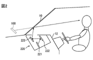
- the HUD device 220 will be described with reference to FIG.
- the HUD device 220 is provided on the instrument panel 12 of the own vehicle, and includes a display 221, a plane mirror 222, and a concave mirror 223.
- the HUD device 220 projects an image on the front windshield 10 under the control of the HCU 20.
- the HUD device 220 projects a display image formed by the display unit 221 onto a projection area defined on the front windshield 10 as a projection member through an optical system such as a plane mirror 222 and a concave mirror 223. More specifically, an image displayed on the display 221 (that is, a display image) is reflected by the plane mirror 222, then enlarged by the concave mirror 223, and projected onto a projection area defined on the front windshield 10. .
- the projection area is assumed to be located in front of the driver's seat, for example.
- the display 221 is, for example, a TFT liquid crystal panel, and outputs light of a display image drawn on the liquid crystal panel by transmitting light from the backlight.
- the luminous flux of the display image reflected on the vehicle interior side by the front windshield 10 is perceived by the driver sitting in the driver's seat. Further, the light flux from the foreground as the scenery existing in front of the own vehicle that is transmitted through the front windshield 10 formed of translucent glass is also perceived by the driver sitting in the driver's seat. As a result, the driver can visually recognize the virtual image 100 of the display image formed in front of the front windshield 10 with a part of the foreground. That is, the HUD device 220 superimposes and displays the virtual image 100 on the foreground of the host vehicle to realize a so-called AR (Augmented Reality) display. As the display image, there are a moving attribute image whose position is changed in accordance with a target in the foreground to be superimposed and a fixed attribute image whose position is fixed regardless of the foreground.
- the virtual image 100 is displayed so that the upper side of the virtual image 100 can be seen more distally than the lower side when viewed from the driver.
- a description will be given by taking as an example a case where the vehicle is tilted in the front-rear direction of the vehicle. This eliminates the use of two indicators: a display for displaying the virtual image 100 so as to be visible on the proximal side of the driver and a display for displaying the virtual image 100 so as to be visible on the distal side of the driver.
- the virtual image 100 can be easily viewed as being displayed from the proximal side to the distal side. Note that the present invention is not necessarily limited to this configuration, and the virtual image 100 may be displayed without being tilted in the front-rear direction of the host vehicle.
- the display 221 is a TFT liquid crystal panel as an example, but the present invention is not necessarily limited thereto.
- another type of display device may be used, and the optical system is not limited to the above-described one, such as using a reflective screen instead of the flat mirror 222.
- the projection member on which the HUD device 220 projects the display image is not limited to the front windshield 10 and may be a light-transmitting combiner.
- a device that displays an image may be used as the display device 22. Examples include a combination meter display, CID (Center Information Display), and the like.
- the HCU 20 is configured mainly by a microcomputer including a processor, a volatile memory, a nonvolatile memory, an I / O, and a bus for connecting them, and is connected to the HUD device 220.
- the HCU 20 controls display on the HUD device 220 by executing a control program stored in the nonvolatile memory.
- the HCU 20 corresponds to a moving body display control device. Executing this control program by the processor corresponds to executing a display control method for a moving body corresponding to the control program.
- the memory is a non-transitory storage medium that stores computer-readable programs and data in a non-transitory manner.
- the non-transitional tangible storage medium is realized by a semiconductor memory or a magnetic disk.
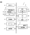
- the HCU 20 includes an information processing block 200 and a display control block 210 as functional blocks regarding display control in the HUD device 220.
- the functions executed by the HCU 20 may be configured by hardware using one or a plurality of ICs.
- some or all of the functional blocks provided in the HCU 20 may be realized by a combination of execution of software by a processor and hardware members.
- the information processing block 200 selectively acquires information necessary for display control in the display control block 210 among various information output to the in-vehicle LAN. In addition, the information processing block 200 performs processing for converting the acquired information into a state suitable for display control. As illustrated in FIG. 3, the information processing block 200 includes a determination information acquisition unit 201, a room brightness acquisition unit 202, a front brightness acquisition unit 203, and a pitching information acquisition unit 204 as sub function blocks.
- the determination information acquisition unit 201 acquires information necessary for determining the contents to be displayed on the HUD device 220.
- information for determining the content of the image drawn on the display 221 of the HUD device 220 (hereinafter, content determination information) is acquired.
- the content determination information the vehicle position output from the ADAS locator 3, the route searched by the navigation device 7, the map data stored in the map DB, the traveling environment recognized by the automatic driving ECU 8, the automatic driving ECU 8 There are a travel plan to be generated, sensing information in the vehicle state sensor 5, operation input information in the operation device 21, setting of an automatic driving function in the automatic driving ECU 8, operation information, and the like.
- the vehicle is equipped with devices that monitor the driver, such as a device that detects the direction of the driver's line of sight, a sensor that detects whether the driver of the vehicle is holding the steering wheel, It is good also as a structure which the information acquisition part 201 for determination acquires the monitoring result of the driver in an apparatus as information for content determination.
- the indoor brightness acquisition unit 202 acquires the illuminance of the vehicle interior detected by the indoor illuminance sensor 51.
- the front brightness acquisition unit 203 acquires the front illuminance detected by the front illuminance sensor 41.
- the pitching information acquisition unit 204 acquires pitching information that is sequentially acquired from the height sensor 52 and indicates the pitching state of the vehicle.
- the display control block 210 controls the display on the HUD device 220 based on the information acquired by the information processing block 200. As illustrated in FIG. 3, the display control block 210 includes a first drawing control unit 211, a second drawing control unit 213, and an arbitration synthesis processing unit 216 as sub function blocks.
- the first drawing control unit 211 and the second drawing control unit 213 generate image data of a display image to be drawn on the display 221 of the HUD device 220 based on information acquired by the information processing block 200.
- the first drawing control unit 211 and the second drawing control unit 213 correspond to a drawing control unit.
- the first drawing control unit 211 and the second drawing control unit 213 draw the display image on the display unit 221 by outputting the generated image data to the display unit 221.
- the first drawing control unit 211 and the second drawing control unit 213 change the content and arrangement mode of the display image according to the content determination information acquired by the determination information acquisition unit 201.
- a display image belonging to the fixed attribute image is referred to as a fixed attribute display
- a display image belonging to the movement attribute image is referred to as a movement attribute display.
- the first drawing control unit 211 generates fixed attribute display image data based on information for fixed attribute display in the information acquired by the information processing block 200.
- the second drawing control unit 213 generates image data for movement attribute display based on the information for movement attribute display in the information acquired by the information processing block 200. That is, the first drawing control unit 211 draws the fixed attribute display on the display 221, and the second drawing control unit 213 draws the movement attribute display on the display 221.
- an image showing information on the instrument of the own vehicle an image showing a setting state of the function of the own vehicle such as an automatic driving function, and an operating state of the automatic driving function
- An image showing the content of the traffic sign on the running road an image showing the monitoring state of the driver, and the like.
- Examples of the image showing the information of the own vehicle meter include an image showing the vehicle speed.
- As an image showing the setting state of the function of the vehicle such as the automatic driving function there is an icon image showing whether the automatic driving function such as the ACC (Adaptive Cruise Control) function is on or off, or whether the route guidance function is on or off. Can be mentioned.
- As an image which shows the operation state of an automatic driving function the icon image etc. which show the presence or absence of operation
- Examples of the image indicating the restriction information on the road being traveled include an icon image indicating the contents of a road sign such as a speed restriction sign for the road being traveled.
- Examples of the image indicating the monitoring state of the driver include an icon image indicating whether or not the steering wheel is gripped by the driver.
- the fixed attribute display is not limited to the example given here.
- the fixed attribute display may be arranged in a corresponding area below the projection area when projected onto the projection area.
- the fixed attribute display is displayed mainly on the proximal side of the driver.
- Examples of the movement attribute display drawn by the second drawing control unit 213 include a turn-by-turn (TBT) image, a lane guidance image indicating a planned lane, a marking image indicating the presence of surrounding facilities, and the following of the own vehicle.
- TBT turn-by-turn
- Examples of the TBT image include a linear or sheet-like image along the road surface of the planned travel route for indicating the planned travel route of the host vehicle.
- Examples of the lane guidance image include an image in which a lane marking of the planned lane is emitted in a pseudo manner, and a linear or sheet-like image showing a range in the lane along the shape of the planned lane.
- the lane guidance image may include an image of an arrow indicating the planned traveling direction.
- Examples of the marking image indicating the tracking target vehicle of the host vehicle include an image surrounding or pointing to the tracking target vehicle.
- Examples of the warning marker image include an image that surrounds or points to the notification target object.
- Examples of the notification target include pedestrians, bicycles, motorcycles, automobiles other than the own vehicle, and the like.
- the movement attribute image is not limited to the example given here.
- the movement attribute display is arranged at a position corresponding to the object of the movement attribute display in the foreground, it may be arranged over the entire projection area. Thereby, the movement attribute display is displayed from the proximal side to the distal side of the driver.
- the first drawing control unit 211 and the second drawing control unit 213 have different layers for drawing a display image on the display 221, and the mediation synthesis processing unit 216 determines which display image is the upper layer. Arbitration as to whether the lower layer is used or not is performed by superposing the upper layer on the lower layer.
- the arbitration composition processing unit 216 sets the movement attribute display layer as a higher layer than the fixed attribute display layer. .
- the arbitration synthesis processing unit 216 sets the fixed attribute display layer as a higher layer than the movement attribute display layer.
- the arbitration synthesis processing unit 216 sets the movement attribute display layer as the upper layer.
- the fixed attribute display layer is set as the upper layer.
- the movement attribute display including emergency information may be an image of the warning marker described above.
- the emergency information may be information on a situation in which it is necessary to alert the presence of a notification target approaching the host vehicle so that an image of a warning marker is displayed.
- FIGS. 4A to 4C are diagrams for explaining an example of a display when emergency information is not included in the movement attribute display.
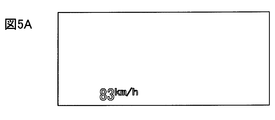
- FIGS. 5A to 5C are diagrams when emergency information is included in the movement attribute display. It is a figure for demonstrating an example of a display.
- FIG. 4A is a fixed attribute display, which is an image showing the speed of the host vehicle.
- FIG. 4B is a movement attribute display, which is an image of lane guidance that also includes an image of an arrow indicating the planned traveling direction.
- FIG. 4C is a diagram illustrating a display example in which the images of FIGS. 4A and 4B are superimposed on the foreground. Vi in FIG. 4C indicates a projection area.
- the fixed attribute display layer is set as the upper layer, while the movement attribute display layer is set as the lower layer.
- An image in which a layer with a fixed attribute display is superimposed on the foreground is displayed. Therefore, an image showing that the vehicle speed of the host vehicle is overwritten on the image of the lane guidance is displayed, and each image is displayed in a more distinguishable manner, and an image showing the vehicle speed of the host vehicle is displayed more easily. Is done.
- FIG. 5A is a fixed attribute display, which is an image showing the speed of the host vehicle.
- FIG. 5B is a movement attribute display, which is an image of a warning marker for alerting the presence of a pedestrian approaching the vehicle.
- FIG. 5C is a diagram showing a display example in which the images of FIGS. 5A and 5B are superimposed and displayed on the foreground. Vi in FIG. 5C indicates a projection area.
- the layer for the movement attribute display is set as the upper layer, while the layer for the fixed attribute display is set as the lower layer, An image on which layers of movement attribute display are superimposed is superimposed on the foreground. Therefore, a display is made in which the image of the warning marker appears to be overwritten on the image indicating the vehicle speed of the host vehicle, and the images of the warning marker are displayed in a more easily viewable manner while displaying each image in a more distinguishable manner.
- the layers may be divided according to the type of display item even if they are the same movement attribute display, or the layers may be divided according to the type of display item even if they are the same fixed attribute display.
- the first drawing control unit 211 includes a first luminance correction unit 212 as shown in FIG.
- the first brightness correction unit 212 changes the apparent brightness of the fixed attribute display by changing the transmittance of the fixed attribute display according to the illuminance in the vehicle interior acquired by the room brightness acquisition unit 202.
- the first brightness correction unit 212 changes the apparent brightness of the fixed attribute display by changing the transmittance of the fixed attribute display according to the illuminance in the vehicle interior acquired by the room brightness acquisition unit 202.
- What is necessary is just to set it as the structure changed to the transmittance
- this correspondence relationship may be made available to the first drawing control unit 211 by storing in advance in the nonvolatile memory of the HCU 20 what is obtained by simulation, experiment, or the like.
- the fixed attribute display mainly displayed on the proximal side of the driver it is necessary to change the luminance of the appearance in accordance with the illuminance in the room of the own vehicle in order to improve the visibility.
- it is possible to improve the visibility by changing the apparent luminance of the fixed attribute display in accordance with the illuminance in the vehicle interior.
- the second drawing control unit 213 includes a second luminance correction unit 214 as shown in FIG.
- the second luminance correction unit 214 changes the apparent luminance of the movement attribute display by changing the transmittance of the movement attribute display according to the illuminance in front of the host vehicle acquired by the front brightness acquisition unit 203.
- the second luminance correction unit 214 changes the apparent luminance of the movement attribute display by changing the transmittance of the movement attribute display according to the illuminance in front of the host vehicle acquired by the front brightness acquisition unit 203.
- What is necessary is just to set it as the structure changed to the transmittance
- this correspondence relationship may be used by the second drawing control unit 213 by storing the correspondence obtained by simulation, experiment, or the like in advance in the nonvolatile memory of the HCU 20.
- the movement attribute display that can be displayed to the far side of the driver, it is necessary to change the luminance of the appearance according to the illuminance in front of the host vehicle in order to improve the visibility.
- the first luminance correction unit 212 and the second luminance correction unit 214 change the transmittance of the display image by a display 221 for performing fixed attribute display and a display 221 for performing movement attribute display. This is because it is common and the backlight is common, and it is difficult to switch the brightness of the backlight separately between the fixed attribute display and the movement attribute display.
- the first luminance correction unit 212 and the second luminance correction unit 214 lower the transmittance of the display image of the lower layer relative to the upper layer image. Thereby, it becomes possible to further improve the visibility of the display image of the upper layer.
- the first luminance correction unit 212 and the second luminance correction unit 214 may be configured to relatively reduce the transmittance of the display image of the lower layer by increasing the transmittance of the display image of the upper layer.
- the transmittance of the display image of the lower layer may be relatively lowered by lowering the transmittance of the display image of the lower layer. It is more preferable that the transmittance of the display image of the lower layer is relatively lowered by lowering the transmittance of the display image of the lower layer.
- the transmittance of the display image of the lower layer may be relatively lowered by lowering the transmittance of the layer image.
- the transmittance of the lower layer image cannot be reduced in order to satisfy the above-mentioned range of transmittance of the display image according to the illuminance, the transmittance of the upper layer image can be increased.
- the transmittance of the display image of the lower layer may be relatively lowered.
- the first luminance correction unit 212 and the second luminance correction unit 214 satisfy the above-described transmittance range of the display image according to the illuminance, and are layers that are lower layers than images of layers that are upper layers. If it is not possible to achieve a relatively low transmittance of the display image, the following may be performed. For example, when the movement attribute display layer is an upper layer, the lower layer layer image is lower than the upper layer image, rather than satisfying the display image transmittance range according to the illuminance described above. What is necessary is just to give priority to making the transmittance
- the display of the layer that is the lower layer with respect to the image of the layer that is the upper layer is to meet the above-described transmittance range of the display image according to the illuminance What is necessary is just to give priority over lowering the transmittance of the image. According to this, it becomes possible to improve the visibility of the display image as necessary, such as giving priority to enhancing the visibility of the movement attribute display including the emergency information.
- the second drawing control unit 213 further includes a position correction unit 215 as shown in FIG.
- the position correction unit 215 draws an image to be drawn on the display unit 221 so as to reduce the shift in the display position of the virtual image 100 of the movement attribute display with respect to the foreground due to pitching.
- Perform position correction to move the position As an example, a correction function for correcting a shift in display position is set in advance by the HCU 20, and correction of position correction is performed by calculating this correction function based on the pitching information acquired by the pitching information acquisition unit 204. What is necessary is just to set it as the structure which calculates a value.
- the correction function is a function indicating a correspondence relationship between the pitching information and a correction value for reducing the shift of the display position of the virtual image 100 of the movement attribute display with respect to the foreground.
- the position correction unit 215 may be configured to perform position correction by moving the drawing position of the movement attribute display according to the calculated correction value.
- the position correction unit 215 performs position correction so as to reduce the shift of the display position due to the pitching of the own vehicle, the shift of the movement attribute display with respect to the target of the movement attribute display in the foreground is reduced, It is possible to prevent the intention of the movement attribute display from becoming difficult to be transmitted to the driver.
- this position correction based on the pitching information is not performed for the fixed attribute display. That is, the first drawing control unit 211 moves the drawing position of the image drawn on the display 221 so as to reduce the shift of the display position of the virtual image 100 of the fixed attribute display with respect to the foreground due to the pitching based on the pitching information. Does not perform position correction. This is because the fixed attribute display is not a display image that changes its position according to the object in the foreground, and therefore, a part of the display image deviates from the projection area by position correction rather than reducing the display position shift due to pitching. This is because it is preferable to prioritize the prevention of chipping.
- FIG. 6 may be configured to start when the power of the HUD device 220 is turned on and the function of the HUD device 220 is turned on.
- the function of the HUD device 220 may be switched on / off according to an input operation received by the operation device 21.
- the power supply of the HUD device 220 may be switched according to on / off of a switch (hereinafter referred to as a power switch) for starting the internal combustion engine or motor generator of the host vehicle.
- a power switch for starting the internal combustion engine or motor generator of the host vehicle.
- the determination information acquisition unit 201, the indoor brightness acquisition unit 202, the front brightness acquisition unit 203, and the pitching information acquisition unit 204 of the information processing block 200 are among the various information output to the in-vehicle LAN. Information necessary for display control in the display control block 210 is selectively acquired.
- the arbitration composition processing unit 216 sets the movement attribute display layer as a higher layer than the fixed attribute display layer, and proceeds to S5.
- the arbitration composition processing unit 216 sets the fixed attribute display layer as a layer higher than the movement attribute display layer, and proceeds to S5.
- the first luminance correction unit 212 lowers the transmittance of the display image of the fixed attribute display layer or the second luminance correction unit 214 moves. Increase the transmittance of the display image of the attribute display layer. Thereby, the transmittance of the display image of the layer with the fixed attribute display is made relatively lower than the transmittance of the display image of the layer with the movement attribute display.
- the first luminance correction unit 212 increases the transmittance of the display image of the fixed attribute display layer, or the second luminance correction unit 214 sets the movement attribute. Decrease the transmittance of the display image of the display layer.
- the transmittance of the display image of the layer with the movement attribute display is made relatively lower than the transmittance of the display image of the layer with the fixed attribute display.
- the first luminance correction unit 212 changes the transmittance of the fixed attribute display according to the illuminance in the vehicle interior acquired by the indoor brightness acquisition unit 202
- the second luminance correction unit 214 acquires the front brightness.
- the transmissivity of the movement attribute display is changed according to the illuminance ahead of the host vehicle acquired by the unit 203.
- the position correction unit 215 corrects the position of the movement attribute display based on the pitching information acquired by the pitching information acquisition unit 204.
- the process of S6 may be performed before the process of S5, or may be performed before the process of S2.
- the arbitration composition processing unit 216 causes the first drawing control unit 211 and the second drawing control unit 213 to draw the upper layer by overlapping the lower layer. For example, when the movement attribute display layer is an upper layer, the movement attribute display layer is drawn on top of the fixed attribute display layer. On the other hand, when the fixed attribute display layer is an upper layer, the fixed attribute display layer is drawn by being superimposed on the movement attribute display layer.
- the movement attribute display and the fixed attribute display are divided into different layers and drawn on one display 221. Even when the virtual image of the display and the fixed attribute display is displayed in combination on the foreground of the vehicle, both can be displayed separately. Therefore, it is possible to suppress a reduction in both visibility due to a mixture of both virtual images.
- the virtual image 100 is superimposed on the foreground of a moving body such as a vehicle by projecting an image onto a projection member such as the front windshield 10, an image of a moving attribute display item and an image of a fixed attribute display item are displayed. Even in a case where both virtual images are displayed on the foreground of the moving object by being projected onto a common projection member, the visibility of both virtual images can be prevented from being lowered.
- the transmittance between the movement attribute display and the fixed attribute display is changed. Therefore, even when the movement attribute display and the fixed attribute display are drawn by one display 221, It is possible to easily switch the apparent luminance individually. Furthermore, according to the configuration of the first embodiment, since it is possible to perform switching for changing the transmittance between the movement attribute display and the fixed attribute display separately, it is possible to make the apparent luminance of both different, It is possible to display both of them easily.
- the movement attribute display layer when the movement attribute display includes emergency information, the movement attribute display layer is set as the upper layer.
- the fixed attribute display layer is set as the upper layer.
- the present invention is not limited to this. Which layer of the movement attribute display and the fixed attribute display is set as the upper layer may be switched according to conditions other than the emergency information, or may be fixed regardless of the conditions. Even in this case, as long as the movement attribute display and the fixed attribute display are divided into different layers, it is possible to display both of them separately, so the visibility of both can be improved by mixing both virtual images. It becomes possible to suppress the decrease.
- the first luminance correction unit 212 changes the transmittance of the fixed attribute display according to the illuminance of the vehicle interior acquired by the indoor brightness acquisition unit 202
- the second luminance correction unit 214 Although the configuration in which the transmittance of the movement attribute display is changed according to the illuminance in front of the host vehicle acquired by the brightness acquisition unit 203 is shown, the configuration is not necessarily limited thereto.
- the configuration may be such that the HCU 20 does not include the room brightness acquisition unit 202 and does not change the transmittance of the fixed attribute display according to the illuminance in the room of the host vehicle.
- the HCU 20 may not include the front brightness acquisition unit 203 and may not change the transmittance of the movement attribute display according to the illuminance ahead of the host vehicle.
- the position correction unit 215 performs the position correction of the movement attribute display based on the pitching information acquired by the pitching information acquisition unit 204.
- the configuration is not necessarily limited thereto.
- the HCU 20 may not include the pitching information acquisition unit 204 and the position correction unit 215 and may not perform position correction of the movement attribute display.
- Embodiment 6 In Embodiment 1, although the example applied when the own vehicle has an automatic driving function was given and demonstrated, it does not necessarily restrict to this. For example, the structure in which the own vehicle does not have an automatic driving function may be sufficient. In this case, the mobile system 1 does not include the automatic operation ECU 8, and the travel environment may be recognized by another ECU.
- the configuration in which the HCU 20 separate from the HUD device 220 performs the function related to the display control in the HUD device 220 is shown, but the configuration is not necessarily limited thereto.
- the control circuit provided in the HUD device 220 may be responsible for functions related to display control in the HUD device 220, or may be configured as the control circuit provided in the combination meter.
- control and the method described in the present disclosure may be realized by a dedicated computer constituting a processor programmed to execute one or a plurality of functions embodied by a computer program.
- control and the method thereof described in the present disclosure may be realized by a dedicated computer that configures a processor with a dedicated hardware logic circuit.
- control and the method described in the present disclosure may be realized by one or more dedicated computers configured by a combination of a processor that executes a computer program and one or more hardware logic circuits.
- the computer program may be stored in a computer-readable non-transition tangible recording medium as instructions executed by the computer.
- each step is expressed as, for example, S1. Further, each step can be divided into a plurality of sub-steps, while a plurality of steps can be combined into one step.
- the embodiment, configuration, and aspect of the display control device for mobile body, the display control method for mobile body, and the control program according to one aspect of the present disclosure have been exemplified, but the embodiment, configuration, and aspect according to the present disclosure are described above.
- the present invention is not limited to each embodiment, each configuration, and each aspect.
- embodiments, configurations, and aspects obtained by appropriately combining technical parts disclosed in different embodiments, configurations, and aspects are also included in the scope of the embodiments, configurations, and aspects according to the present disclosure.
Landscapes
- Engineering & Computer Science (AREA)
- Mechanical Engineering (AREA)
- Chemical & Material Sciences (AREA)
- Combustion & Propulsion (AREA)
- Transportation (AREA)
- Physics & Mathematics (AREA)
- Remote Sensing (AREA)
- Radar, Positioning & Navigation (AREA)
- General Physics & Mathematics (AREA)
- Automation & Control Theory (AREA)
- Optics & Photonics (AREA)
- Instrument Panels (AREA)
- Fittings On The Vehicle Exterior For Carrying Loads, And Devices For Holding Or Mounting Articles (AREA)
- Traffic Control Systems (AREA)
- Navigation (AREA)
- Controls And Circuits For Display Device (AREA)
Applications Claiming Priority (2)
| Application Number | Priority Date | Filing Date | Title |
|---|---|---|---|
| JP2018112068A JP7024619B2 (ja) | 2018-06-12 | 2018-06-12 | 移動体用表示制御装置、移動体用表示制御方法、及び制御プログラム |
| JP2018-112068 | 2018-06-12 |
Publications (1)
| Publication Number | Publication Date |
|---|---|
| WO2019239709A1 true WO2019239709A1 (ja) | 2019-12-19 |
Family
ID=68843119
Family Applications (1)
| Application Number | Title | Priority Date | Filing Date |
|---|---|---|---|
| PCT/JP2019/016112 Ceased WO2019239709A1 (ja) | 2018-06-12 | 2019-04-15 | 移動体用表示制御装置、移動体用表示制御方法、及び制御プログラム |
Country Status (2)
| Country | Link |
|---|---|
| JP (1) | JP7024619B2 (https=) |
| WO (1) | WO2019239709A1 (https=) |
Cited By (1)
| Publication number | Priority date | Publication date | Assignee | Title |
|---|---|---|---|---|
| WO2024111403A1 (ja) * | 2022-11-21 | 2024-05-30 | トヨタ自動車株式会社 | 車両用表示制御装置、車両用表示制御方法及び車両用表示制御プログラム |
Families Citing this family (3)
| Publication number | Priority date | Publication date | Assignee | Title |
|---|---|---|---|---|
| WO2021168698A1 (en) | 2020-02-26 | 2021-09-02 | Baidu.Com Times Technology (Beijing) Co., Ltd. | A mixed regular and open-space trajectory planning method for autonomous driving vehicle |
| EP3891571A4 (en) * | 2020-02-26 | 2021-12-22 | Baidu.com Times Technology (Beijing) Co., Ltd. | TRAJECTORY PLANNING WITH OBSTACLE AVOIDANCE FOR AUTONOMOUS VEHICLES |
| CN113984087A (zh) * | 2021-11-08 | 2022-01-28 | 维沃移动通信有限公司 | 导航方法、装置、电子设备和可读存储介质 |
Citations (5)
| Publication number | Priority date | Publication date | Assignee | Title |
|---|---|---|---|---|
| JP2009053539A (ja) * | 2007-08-28 | 2009-03-12 | Sony Corp | 情報表示装置、情報表示方法およびプログラム |
| WO2016051586A1 (ja) * | 2014-10-03 | 2016-04-07 | 三菱電機株式会社 | 表示制御装置 |
| JP2017013590A (ja) * | 2015-06-30 | 2017-01-19 | 日本精機株式会社 | ヘッドアップディスプレイ装置 |
| JP2017081428A (ja) * | 2015-10-28 | 2017-05-18 | 日本精機株式会社 | 車両用表示装置 |
| JP2018022105A (ja) * | 2016-08-05 | 2018-02-08 | パナソニックIpマネジメント株式会社 | ヘッドアップディスプレイ装置、表示制御方法及び制御プログラム |
Family Cites Families (1)
| Publication number | Priority date | Publication date | Assignee | Title |
|---|---|---|---|---|
| KR101899981B1 (ko) * | 2016-12-02 | 2018-09-19 | 엘지전자 주식회사 | 차량용 헤드 업 디스플레이 |
-
2018
- 2018-06-12 JP JP2018112068A patent/JP7024619B2/ja active Active
-
2019
- 2019-04-15 WO PCT/JP2019/016112 patent/WO2019239709A1/ja not_active Ceased
Patent Citations (5)
| Publication number | Priority date | Publication date | Assignee | Title |
|---|---|---|---|---|
| JP2009053539A (ja) * | 2007-08-28 | 2009-03-12 | Sony Corp | 情報表示装置、情報表示方法およびプログラム |
| WO2016051586A1 (ja) * | 2014-10-03 | 2016-04-07 | 三菱電機株式会社 | 表示制御装置 |
| JP2017013590A (ja) * | 2015-06-30 | 2017-01-19 | 日本精機株式会社 | ヘッドアップディスプレイ装置 |
| JP2017081428A (ja) * | 2015-10-28 | 2017-05-18 | 日本精機株式会社 | 車両用表示装置 |
| JP2018022105A (ja) * | 2016-08-05 | 2018-02-08 | パナソニックIpマネジメント株式会社 | ヘッドアップディスプレイ装置、表示制御方法及び制御プログラム |
Cited By (1)
| Publication number | Priority date | Publication date | Assignee | Title |
|---|---|---|---|---|
| WO2024111403A1 (ja) * | 2022-11-21 | 2024-05-30 | トヨタ自動車株式会社 | 車両用表示制御装置、車両用表示制御方法及び車両用表示制御プログラム |
Also Published As
| Publication number | Publication date |
|---|---|
| JP2019214273A (ja) | 2019-12-19 |
| JP7024619B2 (ja) | 2022-02-24 |
Similar Documents
| Publication | Publication Date | Title |
|---|---|---|
| US20230191911A1 (en) | Vehicle display apparatus | |
| US10362230B2 (en) | In-vehicle display device | |
| US10254539B2 (en) | On-vehicle device, method of controlling on-vehicle device, and computer-readable storage medium | |
| US10452930B2 (en) | Information display device mounted in vehicle including detector | |
| JP6969509B2 (ja) | 車両用表示制御装置、車両用表示制御方法、及び制御プログラム | |
| US11200806B2 (en) | Display device, display control method, and storage medium | |
| CN111034186B (zh) | 周围车辆显示方法及周围车辆显示装置 | |
| JP2015101311A (ja) | 車両情報投影システム | |
| JP2021193020A (ja) | 表示制御装置および表示制御プログラム | |
| US11274934B2 (en) | Information output device, output control method, and storage medium | |
| WO2018173512A1 (ja) | 車両用表示制御装置及び車両用表示ユニット | |
| WO2019239709A1 (ja) | 移動体用表示制御装置、移動体用表示制御方法、及び制御プログラム | |
| JP2021037894A (ja) | 表示制御装置および表示制御プログラム | |
| WO2020189238A1 (ja) | 車両用表示制御装置、車両用表示制御方法、車両用表示制御プログラム | |
| WO2020121810A1 (ja) | 表示制御装置、表示制御プログラムおよびコンピュータ読み出し可能持続的有形記録媒体 | |
| JP7310851B2 (ja) | 車両用表示装置 | |
| JP2021028777A (ja) | 表示制御装置 | |
| US12202510B2 (en) | Display system | |
| JP7172730B2 (ja) | 車両用表示制御装置、車両用表示制御方法、車両用表示制御プログラム | |
| WO2022210171A1 (ja) | 車両用表示システム、車両用表示方法、及び車両用表示プログラム | |
| JP7400242B2 (ja) | 車両用表示制御装置および車両用表示制御方法 | |
| JP2020095033A (ja) | 表示制御装置および表示制御プログラム | |
| JP2020138609A (ja) | 車両用表示制御装置、車両用表示制御方法、車両用表示制御プログラム | |
| JP7014206B2 (ja) | 表示制御装置および表示制御プログラム | |
| JP7206867B2 (ja) | 表示制御装置および表示制御プログラム |
Legal Events
| Date | Code | Title | Description |
|---|---|---|---|
| 121 | Ep: the epo has been informed by wipo that ep was designated in this application |
Ref document number: 19820515 Country of ref document: EP Kind code of ref document: A1 |
|
| NENP | Non-entry into the national phase |
Ref country code: DE |
|
| 122 | Ep: pct application non-entry in european phase |
Ref document number: 19820515 Country of ref document: EP Kind code of ref document: A1 |