WO2019239709A1 - Moving body display control device, moving body display control method, and control program - Google Patents
Moving body display control device, moving body display control method, and control program Download PDFInfo
- Publication number
- WO2019239709A1 WO2019239709A1 PCT/JP2019/016112 JP2019016112W WO2019239709A1 WO 2019239709 A1 WO2019239709 A1 WO 2019239709A1 JP 2019016112 W JP2019016112 W JP 2019016112W WO 2019239709 A1 WO2019239709 A1 WO 2019239709A1
- Authority
- WO
- WIPO (PCT)
- Prior art keywords
- image
- display
- moving body
- attribute
- layer
- Prior art date
Links
Images


Classifications
-
- B—PERFORMING OPERATIONS; TRANSPORTING
- B60—VEHICLES IN GENERAL
- B60K—ARRANGEMENT OR MOUNTING OF PROPULSION UNITS OR OF TRANSMISSIONS IN VEHICLES; ARRANGEMENT OR MOUNTING OF PLURAL DIVERSE PRIME-MOVERS IN VEHICLES; AUXILIARY DRIVES FOR VEHICLES; INSTRUMENTATION OR DASHBOARDS FOR VEHICLES; ARRANGEMENTS IN CONNECTION WITH COOLING, AIR INTAKE, GAS EXHAUST OR FUEL SUPPLY OF PROPULSION UNITS IN VEHICLES
- B60K35/00—Arrangement of adaptations of instruments
-
- B—PERFORMING OPERATIONS; TRANSPORTING
- B60—VEHICLES IN GENERAL
- B60R—VEHICLES, VEHICLE FITTINGS, OR VEHICLE PARTS, NOT OTHERWISE PROVIDED FOR
- B60R11/00—Arrangements for holding or mounting articles, not otherwise provided for
- B60R11/02—Arrangements for holding or mounting articles, not otherwise provided for for radio sets, television sets, telephones, or the like; Arrangement of controls thereof
-
- G—PHYSICS
- G01—MEASURING; TESTING
- G01C—MEASURING DISTANCES, LEVELS OR BEARINGS; SURVEYING; NAVIGATION; GYROSCOPIC INSTRUMENTS; PHOTOGRAMMETRY OR VIDEOGRAMMETRY
- G01C21/00—Navigation; Navigational instruments not provided for in groups G01C1/00 - G01C19/00
- G01C21/26—Navigation; Navigational instruments not provided for in groups G01C1/00 - G01C19/00 specially adapted for navigation in a road network
- G01C21/34—Route searching; Route guidance
- G01C21/36—Input/output arrangements for on-board computers
-
- G—PHYSICS
- G02—OPTICS
- G02B—OPTICAL ELEMENTS, SYSTEMS OR APPARATUS
- G02B27/00—Optical systems or apparatus not provided for by any of the groups G02B1/00 - G02B26/00, G02B30/00
- G02B27/01—Head-up displays
-
- G—PHYSICS
- G08—SIGNALLING
- G08G—TRAFFIC CONTROL SYSTEMS
- G08G1/00—Traffic control systems for road vehicles
- G08G1/16—Anti-collision systems
Abstract
Provided is a moving body display control device that controls a heads-up display device, the moving body display control device comprising: a determination information acquisition unit (201) that acquires content determination information that is information for determining content of an image drawn on a display unit; and drawing control units (211, 213) that draw an image on the display unit according to the content determination information that is acquired by the determination information acquisition unit. The drawing control units draw a moving attribute image that changes position according to a foreground object to be displayed overlaid and a fixed attribute image of which position is fixed regardless of the foreground which are divided into different layers on one display unit.
Description
本出願は、2018年6月12日に出願された日本国特許出願2018-112068号に基づくものであり、ここにその記載内容を参照により援用する。
This application is based on Japanese Patent Application No. 2018-112068 filed on June 12, 2018, the contents of which are incorporated herein by reference.
本開示は、移動体用表示制御装置、移動体用表示制御方法、及び制御プログラムに関するものである。
The present disclosure relates to a moving body display control device, a moving body display control method, and a control program.
ウインドシールド等の投影部材へ画像を投影することによって車両の前景に虚像を重畳表示させるヘッドアップディスプレイ(以下、HUD)が知られている。例えば特許文献1には、ウインドシールドの所定領域に投射されることになる表示項目について、交差点の位置に表示する右折マーク,検出した歩行者の位置に表示する歩行者警告マークといった移動属性の表示項目の画像と、車速を表す速度計情報,エンジンの回転速度を表す回転速度計情報といった固定属性の表示項目の画像とが同時に表示され得ることが開示されている。
2. Description of the Related Art A head-up display (hereinafter referred to as “HUD”) that displays a virtual image superimposed on a foreground of a vehicle by projecting an image onto a projection member such as a windshield is known. For example, Patent Document 1 discloses display of movement attributes such as a right turn mark displayed at an intersection position and a pedestrian warning mark displayed at a detected pedestrian position for display items to be projected on a predetermined area of a windshield. It is disclosed that an item image and an image of a fixed attribute display item such as speedometer information representing vehicle speed and tachometer information representing engine rotation speed can be displayed simultaneously.
移動属性の表示項目の画像と固定属性の表示項目の画像とを同時に表示させる場合、双方の画像が混ざり合って、移動属性の表示項目と固定属性の表示項目との両方の視認性を低下させてしまうおそれがある。
When displaying both the moving attribute display item image and the fixed attribute display item image at the same time, both images are mixed, reducing the visibility of both the moving attribute display item and the fixed attribute display item. There is a risk that.
本開示は、投影部材へ画像を投影することによって移動体の前景に虚像を重畳表示させる際に、移動属性の表示項目の画像と固定属性の表示項目の画像とを共通の投影部材へ投影して移動体の前景に双方の虚像を複合的に表示させる場合であっても、双方の虚像の視認性が低下することを抑える移動体用表示制御装置、移動体用表示制御方法、及び制御プログラムを提供することを目的とする。
The present disclosure projects a moving attribute display item image and a fixed attribute display item image onto a common projection member when a virtual image is superimposed on the foreground of the moving object by projecting the image onto the projection member. Even if both virtual images are displayed on the foreground of the moving object in combination, the display control device for moving object, the display control method for moving object, and the control program that suppress the deterioration of the visibility of both virtual images The purpose is to provide.
本開示の一態様によれば、移動体用表示制御装置は、移動体で用いられ、表示器に描画する画像を投影部材へ投影することによって移動体の前景に虚像を重畳表示させるヘッドアップディスプレイ装置を制御する。移動体用表示制御装置は、表示器に描画する画像の内容を定めるための情報である内容決定用情報を取得する決定用情報取得部と、決定用情報取得部で取得する内容決定用情報に応じて表示器に画像を描画する描画制御部とを備える。描画制御部は、重畳表示させる前景中の対象に合わせて位置を変化させる移動属性の画像と、前景にかかわらず位置が定まっている固定属性の画像とを異なるレイヤに分けて1つの表示器に描画する。
According to one aspect of the present disclosure, a display control apparatus for a moving body is used in a moving body, and a head-up display that superimposes and displays a virtual image on the foreground of the moving body by projecting an image drawn on the display onto a projection member. Control the device. The moving body display control device includes a determination information acquisition unit that acquires information for determining content, which is information for determining the content of an image to be drawn on a display, and content determination information acquired by the determination information acquisition unit. And a drawing control unit for drawing an image on the display. The drawing control unit divides the moving attribute image whose position is changed according to the object in the foreground to be superimposed and the fixed attribute image whose position is fixed regardless of the foreground into different layers on one display device. draw.
本開示の別の態様によれば、移動体用表示制御方法は、移動体で用いられ、表示器に描画する画像を投影部材へ投影することによって移動体の前景に虚像を重畳表示させるヘッドアップディスプレイ装置を制御する。移動体用表示制御方法は、表示器に描画する画像の内容を定めるための情報である内容決定用情報を取得し、取得する内容決定用情報に応じて表示器に画像を描画する際に、重畳表示させる前景中の対象に合わせて位置を変化させる移動属性の画像と、前景にかかわらず位置が定まっている固定属性の画像とを異なるレイヤに分けて1つの表示器に描画する。
According to another aspect of the present disclosure, a moving body display control method is used in a moving body, and a head-up that superimposes and displays a virtual image on the foreground of a moving body by projecting an image to be drawn on a display onto a projection member. Control the display device. When the mobile object display control method acquires content determination information that is information for determining the content of an image to be drawn on the display, and draws an image on the display according to the content determination information to be acquired, The moving attribute image whose position is changed according to the object in the foreground to be superimposed and the fixed attribute image whose position is fixed regardless of the foreground are divided into different layers and drawn on one display.
本開示の別の態様によれば、制御プログラムは、コンピュータを、移動体で用いられ、表示器に描画する画像を投影部材へ投影することによって移動体の前景に虚像を重畳表示させるヘッドアップディスプレイ装置の表示器に描画する画像の内容を定めるための情報である内容決定用情報を取得する決定用情報取得部と、決定用情報取得部で取得する内容決定用情報に応じて表示器に画像を描画する際に、重畳表示させる前景中の対象に合わせて位置を変化させる移動属性の画像と、前景にかかわらず位置が定まっている固定属性の画像とを異なるレイヤに分けて1つの表示器に描画する描画制御部として機能させる。
According to another aspect of the present disclosure, a control program is used in a moving body, and a head-up display that superimposes a virtual image on the foreground of the moving body by projecting an image to be drawn on the display onto a projection member. An information acquisition unit for determining content determination information that is information for determining the content of an image to be drawn on the display of the device, and an image on the display according to the information for content determination acquired by the information acquisition unit for determination When drawing an image, a moving attribute image whose position is changed according to the object in the foreground to be superimposed and a fixed attribute image whose position is fixed regardless of the foreground are divided into different layers, and one display Function as a drawing control unit for drawing.
本開示によれば、表示器に描画する画像を投影部材へ投影することによって移動体の前景に虚像を重畳表示させるヘッドアップディスプレイ装置の表示器に画像を描画する際に、重畳表示させる前景中の対象に合わせて位置を変化させる移動属性の画像と、前景にかかわらず位置が定まっている固定属性の画像とを異なるレイヤに分けて1つの表示器に描画する。よって、移動属性の画像と固定属性の画像との虚像を移動体の前景に複合的に表示させる場合であっても、双方を区別して表示することが可能になる。よって、双方の虚像が混ざり合うことによる双方の視認性の低下を抑えることが可能になる。その結果、投影部材へ画像を投影することによって移動体の前景に虚像を重畳表示させる際に、移動属性の表示項目の画像と固定属性の表示項目の画像とを共通の投影部材へ投影して移動体の前景に双方の虚像を複合的に表示させる場合であっても、双方の虚像の視認性が低下することを抑えることが可能になる。
According to the present disclosure, when an image is drawn on a display of a head-up display device that superimposes a virtual image on a foreground of a moving object by projecting the image to be drawn on the display onto a projection member, A moving attribute image whose position is changed according to the target and a fixed attribute image whose position is fixed regardless of the foreground are divided into different layers and drawn on one display. Therefore, even when a virtual image of a moving attribute image and a fixed attribute image is displayed in combination on the foreground of the moving object, both can be displayed separately. Therefore, it is possible to suppress a reduction in both visibility due to a mixture of both virtual images. As a result, when the virtual image is superimposed on the foreground of the moving object by projecting the image onto the projection member, the image of the display item with the movement attribute and the image of the display item with the fixed attribute are projected onto the common projection member. Even when both virtual images are displayed in combination on the foreground of the moving object, it is possible to suppress a reduction in the visibility of both virtual images.
本開示についての上記および他の目的、特徴や利点は、添付図面を参照した下記詳細な説明から、より明確になる。添付図面において、
移動体システムの概略的な構成の一例を示す図である。
HUD装置の車両への搭載例を示す図である。
HCUの概略的な構成の一例を示す図である。
移動属性表示に緊急情報が含まれない場合の表示制御ブロックでの表示制御による表示の一例について説明を行うための図である。
移動属性表示に緊急情報が含まれない場合の表示制御ブロックでの表示制御による表示の一例について説明を行うための図である。
移動属性表示に緊急情報が含まれない場合の表示制御ブロックでの表示制御による表示の一例について説明を行うための図である。
移動属性表示に緊急情報が含まれる場合の表示制御ブロックでの表示制御による表示の一例について説明を行うための図である。
移動属性表示に緊急情報が含まれる場合の表示制御ブロックでの表示制御による表示の一例について説明を行うための図である。
移動属性表示に緊急情報が含まれる場合の表示制御ブロックでの表示制御による表示の一例について説明を行うための図である。
HCUでの虚像表示制御関連処理の流れの一例を示すフローチャートである。
The above and other objects, features, and advantages of the present disclosure will become more apparent from the following detailed description with reference to the accompanying drawings. In the accompanying drawings,
It is a figure which shows an example of a schematic structure of a mobile body system. It is a figure which shows the example of mounting to a vehicle of a HUD apparatus. It is a figure which shows an example of a schematic structure of HCU. It is a figure for demonstrating an example of the display by the display control in a display control block when emergency information is not included in a movement attribute display. It is a figure for demonstrating an example of the display by the display control in a display control block when emergency information is not included in a movement attribute display. It is a figure for demonstrating an example of the display by the display control in a display control block when emergency information is not included in a movement attribute display. It is a figure for demonstrating an example of the display by the display control in a display control block in case emergency information is included in a movement attribute display. It is a figure for demonstrating an example of the display by the display control in a display control block in case emergency information is included in a movement attribute display. It is a figure for demonstrating an example of the display by the display control in a display control block in case emergency information is included in a movement attribute display. It is a flowchart which shows an example of the flow of the virtual image display control related processing in HCU.
図面を参照しながら、開示のための複数の実施形態を説明する。なお、説明の便宜上、複数の実施形態の間において、それまでの説明に用いた図に示した部分と同一の機能を有する部分については、同一の符号を付し、その説明を省略する場合がある。同一の符号を付した部分については、他の実施形態における説明を参照することができる。
A plurality of embodiments for disclosure will be described with reference to the drawings. For convenience of explanation, among the embodiments, parts having the same functions as those shown in the drawings used in the explanation so far may be given the same reference numerals and explanation thereof may be omitted. is there. For the parts denoted by the same reference numerals, the description in other embodiments can be referred to.
(実施形態1)
(移動体システム1の概略構成)
以下、本実施形態について図面を用いて説明する。移動体システム1は、車両,船舶,航空機といった移動体で用いられるものである。本実施形態では、自動車といった車両に適用される場合の例を挙げて以降の説明を行う。 (Embodiment 1)
(Schematic configuration of mobile system 1)
Hereinafter, the present embodiment will be described with reference to the drawings. Themobile body system 1 is used in mobile bodies such as vehicles, ships, and aircraft. In the present embodiment, the following description will be given by giving an example of application to a vehicle such as an automobile.
(移動体システム1の概略構成)
以下、本実施形態について図面を用いて説明する。移動体システム1は、車両,船舶,航空機といった移動体で用いられるものである。本実施形態では、自動車といった車両に適用される場合の例を挙げて以降の説明を行う。 (Embodiment 1)
(Schematic configuration of mobile system 1)
Hereinafter, the present embodiment will be described with reference to the drawings. The
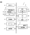
図1に示す移動体システム1は、車両で用いられるものであり、HMI(Human Machine Interface)システム2、ADAS(Advanced Driver Assistance Systems)ロケータ3、周辺監視センサ4、車両状態センサ5、車両制御ECU6、ナビゲーション装置7、及び自動運転ECU8を含んでいる。HMIシステム2、ADASロケータ3、周辺監視センサ4、車両状態センサ5、車両制御ECU6、ナビゲーション装置7、及び自動運転ECU8は、例えば車内LANに接続されているものとする。
A mobile system 1 shown in FIG. 1 is used in a vehicle, and includes an HMI (Human Machine Interface) system 2, an ADAS (Advanced Driver Assistant Systems) locator 3, a peripheral monitoring sensor 4, a vehicle state sensor 5, and a vehicle control ECU 6. , Navigation device 7 and automatic operation ECU 8 are included. It is assumed that the HMI system 2, the ADAS locator 3, the periphery monitoring sensor 4, the vehicle state sensor 5, the vehicle control ECU 6, the navigation device 7, and the automatic driving ECU 8 are connected to the in-vehicle LAN, for example.
ADASロケータ3は、GNSS(Global Navigation Satellite System)受信機、及び慣性センサを備えている。GNSS受信機は、複数の人工衛星からの測位信号を受信する。慣性センサは、例えばジャイロセンサ及び加速度センサを備える。ADASロケータ3は、GNSS受信機で受信する測位信号と、慣性センサの計測結果とを組み合わせることにより、自車の車両位置を逐次測位する。なお、車両位置の測位には、自車に搭載された車速センサから逐次出力される検出結果から求めた走行距離等を用いる構成としてもよい。そして、測位した車両位置を車内LANへ出力する。
The ADAS locator 3 includes a GNSS (Global Navigation Satellite System) receiver and an inertial sensor. The GNSS receiver receives positioning signals from a plurality of artificial satellites. The inertial sensor includes, for example, a gyro sensor and an acceleration sensor. The ADAS locator 3 sequentially measures the position of the vehicle by combining the positioning signal received by the GNSS receiver and the measurement result of the inertial sensor. The vehicle position may be measured using a travel distance obtained from detection results sequentially output from a vehicle speed sensor mounted on the host vehicle. And the measured vehicle position is output to in-vehicle LAN.
ADASロケータ3は、地図データとして、道路形状及び構造物の特徴点の点群からなる三次元地図を格納する地図データベース(以下、地図DB)を備える構成としてもよい。ADASロケータ3は、この三次元地図を用いる場合、GNSS受信機を用いずに、この三次元地図と、道路形状及び構造物の特徴点の点群を検出するLIDAR(Light Detection and Ranging/Laser Imaging Detection and Ranging)等の周辺監視センサ4での検出結果とを用いて、自車の車両位置を特定する構成としてもよい。なお、この三次元地図の地図データは、通信モジュールを介して自車の外部から取得する構成としてもよい。
The ADAS locator 3 may include a map database (hereinafter referred to as a map DB) that stores a three-dimensional map made up of point shapes of road shapes and structure feature points as map data. When this 3D map is used, the ADAS locator 3 does not use a GNSS receiver, but detects this 3D map and the road shape and the point cloud of the feature points of the structure LIDAR (Light Detection and Ranging / Laser Imaging It is good also as a structure which pinpoints the vehicle position of the own vehicle using the detection results in the periphery monitoring sensors 4 such as Detection (Randing). The map data of the three-dimensional map may be obtained from the outside of the own vehicle via the communication module.
周辺監視センサ4は、自車の周辺環境を監視する自律センサである。一例として、周辺監視センサ4は、歩行者,人間以外の動物、自車以外の車両等の移動する動的物標、及び路上の落下物,ガードレール、縁石、及び樹木等の静止している静的物標といった自車周辺の障害物を検出する。他にも、自車周辺の走行区画線等の路面標示を検出する。周辺監視センサ4は、例えば、自車周囲の所定範囲を撮像する周辺監視カメラ、自車周囲の所定範囲に探査波を送信するミリ波レーダ、ソナー、LIDAR等のセンサである。周辺監視カメラは、逐次撮像する撮像画像をセンシング情報として車内LANへ逐次出力する。ソナー、ミリ波レーダ、LIDAR等の探査波を送信するセンサは、検出対象によって反射された反射波を受信した場合に得られる受信信号に基づく走査結果をセンシング情報として車内LANへ逐次出力する。
The surrounding monitoring sensor 4 is an autonomous sensor that monitors the surrounding environment of the vehicle. As an example, the periphery monitoring sensor 4 is a stationary static object such as a pedestrian, a non-human animal, a moving dynamic target such as a vehicle other than the own vehicle, and a fallen object on the road, a guardrail, a curb, and a tree. Detect obstacles around the vehicle such as target. In addition, road markings such as travel lane markings around the vehicle are detected. The surrounding monitoring sensor 4 is, for example, a surrounding monitoring camera that captures a predetermined range around the host vehicle, a millimeter wave radar, a sonar, a LIDAR, or the like that transmits an exploration wave to the predetermined range around the host vehicle. The peripheral monitoring camera sequentially outputs captured images that are sequentially captured to the in-vehicle LAN as sensing information. A sensor that transmits an exploration wave such as sonar, millimeter wave radar, or LIDAR sequentially outputs a scanning result based on a reception signal obtained when a reflected wave reflected by a detection target is received to the in-vehicle LAN as sensing information.
周辺監視センサ4として、自車の前方の照度を検出する照度センサ(以下、前方照度センサ)41を備えることが好ましい。ここでは、照度を明るさの指標として用いる場合の例を示すが、必ずしもこれに限らず、照度以外の指標を用いる構成としてもよい。なお、自車の前方の明るさは、周辺監視カメラのうちの自車の前方の所定範囲を撮像する前方カメラでの前方画像から検出する構成としてもよい。
It is preferable that the periphery monitoring sensor 4 includes an illuminance sensor (hereinafter referred to as a front illuminance sensor) 41 that detects the illuminance in front of the vehicle. Here, an example in which illuminance is used as an index of brightness is shown, but the present invention is not necessarily limited thereto, and a configuration using an index other than illuminance may be employed. Note that the brightness in front of the host vehicle may be detected from a front image of a front camera that captures a predetermined range in front of the host vehicle of the peripheral monitoring cameras.
車両状態センサ5は、自車の各種状態を検出するためのセンサ群である。車両状態センサ5としては、自車の車速を検出する車速センサ,自車の操舵角を検出する操舵センサ,自車のアクセルペダルの開度を検出するアクセルポジションセンサ,自車のブレーキペダルの踏み込み量を検出するブレーキ踏力センサ等がある。車両状態センサ5は、検出するセンシング情報を車内LANへ出力する。なお、車両状態センサ5で検出するセンシング情報は、自車に搭載されるECUを介して車内LANへ出力される構成であってもよい。
The vehicle state sensor 5 is a sensor group for detecting various states of the host vehicle. The vehicle state sensor 5 includes a vehicle speed sensor that detects the vehicle speed of the host vehicle, a steering sensor that detects the steering angle of the host vehicle, an accelerator position sensor that detects the opening degree of the accelerator pedal of the host vehicle, and a depression of the brake pedal of the host vehicle. There are brake pedal force sensors that detect the amount. The vehicle state sensor 5 outputs sensing information to be detected to the in-vehicle LAN. The sensing information detected by the vehicle state sensor 5 may be configured to be output to the in-vehicle LAN via an ECU mounted on the own vehicle.
車両状態センサ5として、自車の室内の照度を検出する照度センサ(以下、室内照度センサ)51を備えたり、ハイトセンサ52を備えたりすることが好ましい。ここでも、照度を明るさの指標として用いる場合の例を示したが、必ずしもこれに限らず、照度以外の指標を用いる構成としてもよい。
It is preferable that the vehicle state sensor 5 includes an illuminance sensor (hereinafter referred to as an indoor illuminance sensor) 51 that detects the illuminance in the room of the host vehicle or a height sensor 52. Here, an example in which illuminance is used as an index of brightness has been shown, but the present invention is not necessarily limited thereto, and a configuration using an index other than illuminance may be employed.
ハイトセンサ52は、自車の車高を検出するセンサである。ハイトセンサ52は、例えば自車の各輪の近傍に設けられており、懸架装置の動作によって上下に変位する各輪について、車体に対する沈み込み量を計測する。ハイトセンサ52は、各輪の沈み込み量を計測した計測データを逐次出力する。つまり、ハイトセンサ52は、自車のピッチングの状態を示す情報(以下、ピッチング情報)を逐次出力する。ピッチングは、自車の左右方向を軸にしたシーソーの挙動のような回転運動であって、前後上下運動と言い換えることもできる。なお、ハイトセンサ52は、車体から路面へ向けて照射した超音波又はレーザ光により、車体から路面までの距離を姿勢変化情報として直接的に計測する構成であってもよい。
The height sensor 52 is a sensor that detects the height of the host vehicle. The height sensor 52 is provided, for example, in the vicinity of each wheel of the host vehicle, and measures the amount of sinking with respect to the vehicle body for each wheel that is displaced up and down by the operation of the suspension device. The height sensor 52 sequentially outputs measurement data obtained by measuring the amount of depression of each wheel. That is, the height sensor 52 sequentially outputs information indicating the pitching state of the own vehicle (hereinafter, pitching information). Pitching is a rotational motion like the behavior of a seesaw with the left-right direction of the host vehicle as an axis, and can be rephrased as a longitudinal motion. The height sensor 52 may be configured to directly measure the distance from the vehicle body to the road surface as posture change information using ultrasonic waves or laser light irradiated from the vehicle body toward the road surface.
車両制御ECU6は、自車の加減速制御及び/又は操舵制御を行う電子制御装置である。車両制御ECU6としては、操舵制御を行う操舵ECU、加減速制御を行うパワーユニット制御ECU及びブレーキECU等がある。車両制御ECU6は、自車に搭載されたアクセルポジションセンサ、ブレーキ踏力センサ、舵角センサ、車輪速センサ等の各センサから出力される検出信号を取得し、電子制御スロットル、ブレーキアクチュエータ、EPS(Electric Power Steering)モータ等の各走行制御デバイスへ制御信号を出力する。車両制御ECU6は、上述の各センサの検出信号を車内LANへ出力可能である。
The vehicle control ECU 6 is an electronic control device that performs acceleration / deceleration control and / or steering control of the host vehicle. The vehicle control ECU 6 includes a steering ECU that performs steering control, a power unit control ECU that performs acceleration / deceleration control, a brake ECU, and the like. The vehicle control ECU 6 obtains detection signals output from sensors such as an accelerator position sensor, a brake pedal force sensor, a rudder angle sensor, and a wheel speed sensor mounted on the host vehicle, and performs electronic control throttle, brake actuator, EPS (Electric Power Steering) Outputs control signals to each travel control device such as a motor. The vehicle control ECU 6 can output the detection signals of the above-described sensors to the in-vehicle LAN.
ナビゲーション装置7は、地図データを格納した地図DBを備え、設定される目的地までの時間優先,距離優先等の条件を満たす経路を探索し、その探索した経路に従った経路案内を行う。地図DBは、不揮発性メモリであって、リンクデータ、セグメントデータ、ノードデータ、道路形状等の地図データを格納しているものとすればよい。なお、地図データには、道路形状及び構造物の特徴点の点群からなる三次元地図を含む構成であってもよい。
The navigation device 7 includes a map DB storing map data, searches for a route that satisfies conditions such as time priority and distance priority to a set destination, and performs route guidance according to the searched route. The map DB may be a non-volatile memory that stores map data such as link data, segment data, node data, and road shapes. Note that the map data may include a three-dimensional map including a road shape and a point group of feature points of the structure.
自動運転ECU8は、車両制御ECU6を制御することにより、ドライバによる運転操作の代行を行う自動運転機能を実行する。自動運転ECU8は、ADASロケータ3から取得する自車の車両位置及び三次元地図の地図データ,周辺監視センサ4でのセンシング情報,ナビゲーション装置7から取得する地図データをもとに、自車の走行環境を認識する。一例としては、周辺監視センサ4でのセンシング情報から、自車周辺の物体の形状及び移動状態を認識したり、自車周辺の路面標示の形状を認識したりする。そして、自車の車両位置及び地図データと組み合わせることで、実際の走行環境を三次元で再現した仮想空間を生成する。
The automatic driving ECU 8 controls the vehicle control ECU 6 to execute an automatic driving function for performing a driving operation by the driver. The autonomous driving ECU 8 travels based on the vehicle position and three-dimensional map data acquired from the ADAS locator 3, sensing information from the surrounding monitoring sensor 4, and map data acquired from the navigation device 7. Recognize the environment. As an example, the shape and movement state of an object around the own vehicle are recognized from the sensing information of the surrounding monitoring sensor 4, or the shape of a road marking around the own vehicle is recognized. Then, by combining with the vehicle position of the own vehicle and the map data, a virtual space in which the actual traveling environment is reproduced in three dimensions is generated.
自動運転ECU8は、認識した走行環境に基づき、自動運転機能によって自車を自動走行させるための走行計画を生成する。走行計画としては、長中期の走行計画と、短期の走行計画とが生成される。長中期の走行計画では、設定された目的地に自車を向かわせるための経路が規定される。長中期の走行計画については、ナビゲーション装置7で探索した経路を用いる構成としてもよい。短期の走行計画では、生成した自車の周囲の仮想空間を用いて、長中期の走行計画に従った走行を実現するための予定走行軌跡が規定される。具体的に、車線追従及び車線変更のための操舵、速度調整のための加減速、並びに衝突回避のための急制動等の実行が、短期の走行計画に基づいて決定される。
The automatic driving ECU 8 generates a driving plan for automatically driving the vehicle by the automatic driving function based on the recognized driving environment. As the travel plan, a long-term travel plan and a short-term travel plan are generated. In the long-term driving plan, a route for directing the vehicle to a set destination is defined. About the long-term driving plan, it is good also as a structure using the route searched with the navigation apparatus 7. FIG. In the short-term travel plan, a planned travel locus for realizing travel according to the long-term travel plan is defined using the generated virtual space around the vehicle. Specifically, execution of steering for lane tracking and lane change, acceleration / deceleration for speed adjustment, and sudden braking for collision avoidance is determined based on a short-term travel plan.
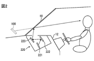
HMIシステム2は、HCU(Human Machine Interface Control Unit)20、操作デバイス21、及び表示装置22を備えており、自車のユーザであるドライバからの入力操作を受け付けたり、自車のドライバに向けて情報を提示したりする。操作デバイス21は、自車のドライバが操作するスイッチ群である。操作デバイス21は、各種の設定を行うために用いられる。例えば、操作デバイス21としては、自車のステアリングのスポーク部に設けられたステアリングスイッチ等がある。表示装置22としては、ヘッドアップディスプレイ(HUD)装置220を用いる。ここで、図2を用いてHUD装置220について説明を行う。
The HMI system 2 includes an HCU (Human Machine Interface Control Unit) 20, an operation device 21, and a display device 22. The HMI system 2 accepts an input operation from a driver who is a user of the own vehicle or is directed toward the driver of the own vehicle. To present information. The operation device 21 is a switch group operated by the driver of the own vehicle. The operation device 21 is used for performing various settings. For example, the operation device 21 includes a steering switch provided in a spoke spoke portion of the own vehicle. A head-up display (HUD) device 220 is used as the display device 22. Here, the HUD device 220 will be described with reference to FIG.
図2に示すようにHUD装置220は、自車のインストルメントパネル12に設けられ、表示器221、平面ミラー222、及び凹面ミラー223を有する。HUD装置220は、HCU20の制御下で画像をフロントウインドシールド10に投影する。HUD装置220は、表示器221によって形成される表示画像を、平面ミラー222及び凹面ミラー223といった光学系を通じて、投影部材としてのフロントウインドシールド10に既定された投影領域に投影する。より詳しくは、表示器221に表示される画像(つまり、表示画像)が、平面ミラー222で反射された後、凹面ミラー223により拡大され、フロントウインドシールド10に既定された投影領域に投影される。投影領域は、例えば運転席前方に位置するものとする。表示器221は、例えばTFT液晶パネルであって、バックライトからの光を透過させることで、液晶パネルに描画する表示画像の光を出力する。
As shown in FIG. 2, the HUD device 220 is provided on the instrument panel 12 of the own vehicle, and includes a display 221, a plane mirror 222, and a concave mirror 223. The HUD device 220 projects an image on the front windshield 10 under the control of the HCU 20. The HUD device 220 projects a display image formed by the display unit 221 onto a projection area defined on the front windshield 10 as a projection member through an optical system such as a plane mirror 222 and a concave mirror 223. More specifically, an image displayed on the display 221 (that is, a display image) is reflected by the plane mirror 222, then enlarged by the concave mirror 223, and projected onto a projection area defined on the front windshield 10. . The projection area is assumed to be located in front of the driver's seat, for example. The display 221 is, for example, a TFT liquid crystal panel, and outputs light of a display image drawn on the liquid crystal panel by transmitting light from the backlight.
フロントウインドシールド10によって車室内側に反射される表示画像の光束は、運転席に着座するドライバによって知覚される。また、透光性ガラスにより形成されるフロントウインドシールド10を透過してくる、自車の前方に存在する風景としての前景からの光束も、運転席に着座するドライバによって知覚される。これにより、ドライバは、フロントウインドシールド10の前方にて結像される表示画像の虚像100を、前景の一部と重ねて視認可能となる。つまり、HUD装置220は、自車の前景に虚像100を重畳表示し、所謂AR(Augmented Reality)表示を実現する。表示画像としては、重畳表示させる前景中の対象に合わせて位置を変化させる移動属性の画像と、前景にかかわらず位置が定まっている固定属性の画像とがある。
The luminous flux of the display image reflected on the vehicle interior side by the front windshield 10 is perceived by the driver sitting in the driver's seat. Further, the light flux from the foreground as the scenery existing in front of the own vehicle that is transmitted through the front windshield 10 formed of translucent glass is also perceived by the driver sitting in the driver's seat. As a result, the driver can visually recognize the virtual image 100 of the display image formed in front of the front windshield 10 with a part of the foreground. That is, the HUD device 220 superimposes and displays the virtual image 100 on the foreground of the host vehicle to realize a so-called AR (Augmented Reality) display. As the display image, there are a moving attribute image whose position is changed in accordance with a target in the foreground to be superimposed and a fixed attribute image whose position is fixed regardless of the foreground.
本実施形態では、平面ミラー222及び凹面ミラー223といった光学系に対して表示器221を傾けることで、ドライバから見て虚像100の上方が下方よりも遠位側により見え易くなるように虚像100を自車の前後方向に傾けて表示させる場合を例に挙げて説明を行う。これにより、虚像100がドライバの近位側に見えるように表示させるための表示器と虚像100がドライバの遠位側に見えるように表示させるための表示器との2つの表示器を用いなくても、虚像100が近位側から遠位側にわたって表示されているように見せ易くなる。なお、必ずしもこの構成に限らず、虚像100を自車の前後方向に傾けずに表示させる構成としてもよい。
In the present embodiment, by tilting the display 221 with respect to the optical system such as the flat mirror 222 and the concave mirror 223, the virtual image 100 is displayed so that the upper side of the virtual image 100 can be seen more distally than the lower side when viewed from the driver. A description will be given by taking as an example a case where the vehicle is tilted in the front-rear direction of the vehicle. This eliminates the use of two indicators: a display for displaying the virtual image 100 so as to be visible on the proximal side of the driver and a display for displaying the virtual image 100 so as to be visible on the distal side of the driver. However, the virtual image 100 can be easily viewed as being displayed from the proximal side to the distal side. Note that the present invention is not necessarily limited to this configuration, and the virtual image 100 may be displayed without being tilted in the front-rear direction of the host vehicle.
本実施形態では、表示器221がTFT液晶パネルである場合を例に挙げて以降の説明を行うが、必ずしもこれに限らない。例えば、表示画像を描画可能であれば、他の方式の表示器であっても構わず、光学系も平面ミラー222の代わりに反射型のスクリーンを用いるなど上述したものに限らない。なお、HUD装置220が表示画像を投影する投影部材は、フロントウインドシールド10に限らず、透光性コンバイナであっても構わない。また、表示装置22として、HUD装置220の他にも、画像を表示する装置を用いる構成としてもよい。一例としては、コンビネーションメータのディスプレイ,CID(Center Information Display)等がある。
In the present embodiment, the following description is given by taking the case where the display 221 is a TFT liquid crystal panel as an example, but the present invention is not necessarily limited thereto. For example, as long as a display image can be drawn, another type of display device may be used, and the optical system is not limited to the above-described one, such as using a reflective screen instead of the flat mirror 222. The projection member on which the HUD device 220 projects the display image is not limited to the front windshield 10 and may be a light-transmitting combiner. In addition to the HUD device 220, a device that displays an image may be used as the display device 22. Examples include a combination meter display, CID (Center Information Display), and the like.
HCU20は、プロセッサ、揮発性メモリ、不揮発性メモリ、I/O、これらを接続するバスを備えるマイクロコンピュータを主体として構成され、HUD装置220に接続されている。HCU20は、不揮発性メモリに記憶された制御プログラムを実行することにより、HUD装置220での表示を制御する。このHCU20が移動体用表示制御装置に相当する。プロセッサがこの制御プログラムを実行することは、制御プログラムに対応する移動体用表示制御方法が実行されることに相当する。メモリは、コンピュータによって読み取り可能なプログラム及びデータを非一時的に格納する非遷移的実体的記憶媒体(non-transitory tangible storage medium)である。また、非遷移的実体的記憶媒体は、半導体メモリ又は磁気ディスクなどによって実現される。なお、HUD装置220による表示の制御に関するHCU20の構成については以下で詳述する。
The HCU 20 is configured mainly by a microcomputer including a processor, a volatile memory, a nonvolatile memory, an I / O, and a bus for connecting them, and is connected to the HUD device 220. The HCU 20 controls display on the HUD device 220 by executing a control program stored in the nonvolatile memory. The HCU 20 corresponds to a moving body display control device. Executing this control program by the processor corresponds to executing a display control method for a moving body corresponding to the control program. The memory is a non-transitory storage medium that stores computer-readable programs and data in a non-transitory manner. The non-transitional tangible storage medium is realized by a semiconductor memory or a magnetic disk. The configuration of the HCU 20 relating to display control by the HUD device 220 will be described in detail below.
(HCU20の概略構成)
ここで、図3を用いてHCU20の概略構成についての説明を行う。HCU20は、HUD装置220での表示の制御に関して、図3に示すように、情報処理ブロック200及び表示制御ブロック210を機能ブロックとして備える。なお、HCU20が実行する機能の一部又は全部を、一つ或いは複数のIC等によりハードウェア的に構成してもよい。また、HCU20が備える機能ブロックの一部又は全部は、プロセッサによるソフトウェアの実行とハードウェア部材の組み合わせによって実現されてもよい。 (Schematic configuration of HCU20)
Here, a schematic configuration of theHCU 20 will be described with reference to FIG. As shown in FIG. 3, the HCU 20 includes an information processing block 200 and a display control block 210 as functional blocks regarding display control in the HUD device 220. Note that some or all of the functions executed by the HCU 20 may be configured by hardware using one or a plurality of ICs. Also, some or all of the functional blocks provided in the HCU 20 may be realized by a combination of execution of software by a processor and hardware members.
ここで、図3を用いてHCU20の概略構成についての説明を行う。HCU20は、HUD装置220での表示の制御に関して、図3に示すように、情報処理ブロック200及び表示制御ブロック210を機能ブロックとして備える。なお、HCU20が実行する機能の一部又は全部を、一つ或いは複数のIC等によりハードウェア的に構成してもよい。また、HCU20が備える機能ブロックの一部又は全部は、プロセッサによるソフトウェアの実行とハードウェア部材の組み合わせによって実現されてもよい。 (Schematic configuration of HCU20)
Here, a schematic configuration of the
情報処理ブロック200は、車内LANに出力された種々の情報のうちで、表示制御ブロック210での表示制御に必要な情報を選択的に取得する。加えて情報処理ブロック200は、取得した情報を表示制御に適した状態に変換する処理を行う。情報処理ブロック200は、図3に示すように、決定用情報取得部201、室内明るさ取得部202、前方明るさ取得部203、及びピッチング情報取得部204をサブ機能ブロックとして備える。
The information processing block 200 selectively acquires information necessary for display control in the display control block 210 among various information output to the in-vehicle LAN. In addition, the information processing block 200 performs processing for converting the acquired information into a state suitable for display control. As illustrated in FIG. 3, the information processing block 200 includes a determination information acquisition unit 201, a room brightness acquisition unit 202, a front brightness acquisition unit 203, and a pitching information acquisition unit 204 as sub function blocks.
決定用情報取得部201は、HUD装置220で表示させる内容を定めるために必要な情報を取得する。言い換えると、HUD装置220の表示器221に描画する画像の内容を定めるための情報(以下、内容決定用情報)を取得する。内容決定用情報の一例としては、ADASロケータ3から出力される車両位置,ナビゲーション装置7で探索する経路,地図DBに格納されている地図データ,自動運転ECU8で認識した走行環境,自動運転ECU8で生成する走行計画,車両状態センサ5でのセンシング情報,操作デバイス21での操作入力情報,自動運転ECU8での自動運転機能の設定及び動作情報等がある。
The determination information acquisition unit 201 acquires information necessary for determining the contents to be displayed on the HUD device 220. In other words, information for determining the content of the image drawn on the display 221 of the HUD device 220 (hereinafter, content determination information) is acquired. As an example of the content determination information, the vehicle position output from the ADAS locator 3, the route searched by the navigation device 7, the map data stored in the map DB, the traveling environment recognized by the automatic driving ECU 8, the automatic driving ECU 8 There are a travel plan to be generated, sensing information in the vehicle state sensor 5, operation input information in the operation device 21, setting of an automatic driving function in the automatic driving ECU 8, operation information, and the like.
なお、自車のドライバの視線方向を検出する装置,自車のドライバがステアリングホイールを把持しているかを検出するセンサ等のドライバをモニタリングする機器を自車に備えている場合には、これらの機器でのドライバのモニタリング結果を内容決定用情報として決定用情報取得部201が取得する構成としてもよい。
If the vehicle is equipped with devices that monitor the driver, such as a device that detects the direction of the driver's line of sight, a sensor that detects whether the driver of the vehicle is holding the steering wheel, It is good also as a structure which the information acquisition part 201 for determination acquires the monitoring result of the driver in an apparatus as information for content determination.
室内明るさ取得部202は、室内照度センサ51で検出する自車の室内の照度を取得する。前方明るさ取得部203は、前方照度センサ41で検出する自車の前方の照度を取得する。ピッチング情報取得部204は、ハイトセンサ52から逐次取得される、自車のピッチングの状態を示すピッチング情報を取得する。
The indoor brightness acquisition unit 202 acquires the illuminance of the vehicle interior detected by the indoor illuminance sensor 51. The front brightness acquisition unit 203 acquires the front illuminance detected by the front illuminance sensor 41. The pitching information acquisition unit 204 acquires pitching information that is sequentially acquired from the height sensor 52 and indicates the pitching state of the vehicle.
表示制御ブロック210は、情報処理ブロック200で取得する情報をもとに、HUD装置220での表示に関する制御を行う。図3に示すように、表示制御ブロック210は、第1描画制御部211、第2描画制御部213、及び調停合成処理部216をサブ機能ブロックとして備える。
The display control block 210 controls the display on the HUD device 220 based on the information acquired by the information processing block 200. As illustrated in FIG. 3, the display control block 210 includes a first drawing control unit 211, a second drawing control unit 213, and an arbitration synthesis processing unit 216 as sub function blocks.
第1描画制御部211及び第2描画制御部213は、HUD装置220の表示器221に描画する表示画像の画像データを、情報処理ブロック200で取得する情報に基づいて生成する。この第1描画制御部211及び第2描画制御部213が描画制御部に相当する。第1描画制御部211及び第2描画制御部213は、生成する画像データを表示器221に出力することで、表示器221に表示画像を描画する。第1描画制御部211及び第2描画制御部213は、表示画像の内容及び配置の態様を、決定用情報取得部201で取得する内容決定用情報に応じて変更する。以降では、固定属性の画像に属する表示画像を固定属性表示と呼び、移動属性の画像に属する表示画像を移動属性表示と呼ぶ。
The first drawing control unit 211 and the second drawing control unit 213 generate image data of a display image to be drawn on the display 221 of the HUD device 220 based on information acquired by the information processing block 200. The first drawing control unit 211 and the second drawing control unit 213 correspond to a drawing control unit. The first drawing control unit 211 and the second drawing control unit 213 draw the display image on the display unit 221 by outputting the generated image data to the display unit 221. The first drawing control unit 211 and the second drawing control unit 213 change the content and arrangement mode of the display image according to the content determination information acquired by the determination information acquisition unit 201. Hereinafter, a display image belonging to the fixed attribute image is referred to as a fixed attribute display, and a display image belonging to the movement attribute image is referred to as a movement attribute display.
第1描画制御部211は、情報処理ブロック200で取得する情報のうちの固定属性表示用の情報に基づいて、固定属性表示の画像データを生成する。第2描画制御部213は、情報処理ブロック200で取得する情報のうちの移動属性表示用の情報に基づいて、移動属性表示の画像データを生成する。つまり、第1描画制御部211は、固定属性表示を表示器221に描画し、第2描画制御部213は、移動属性表示を表示器221に描画する。
The first drawing control unit 211 generates fixed attribute display image data based on information for fixed attribute display in the information acquired by the information processing block 200. The second drawing control unit 213 generates image data for movement attribute display based on the information for movement attribute display in the information acquired by the information processing block 200. That is, the first drawing control unit 211 draws the fixed attribute display on the display 221, and the second drawing control unit 213 draws the movement attribute display on the display 221.
第1描画制御部211で描画する固定属性表示の一例としては、自車の計器の情報を示す画像,自動運転機能等の自車の機能の設定状態を示す画像,自動運転機能の動作状態を示す画像,走行中の道路の交通標識の内容を示す画像,ドライバのモニタリング状態を示す画像等がある。
As an example of the fixed attribute display drawn by the first drawing control unit 211, an image showing information on the instrument of the own vehicle, an image showing a setting state of the function of the own vehicle such as an automatic driving function, and an operating state of the automatic driving function An image showing the content of the traffic sign on the running road, an image showing the monitoring state of the driver, and the like.
自車の計器の情報を示す画像としては、車速を示す画像等が挙げられる。自動運転機能等の自車の機能の設定状態を示す画像としては、ACC(Adaptive Cruise Control)機能等の自動運転機能のオンオフであったり、経路案内機能のオンオフであったりを示すアイコン画像等が挙げられる。自動運転機能の動作状態を示す画像としては、自動運転機能の動作の有無を示すアイコン画像等が挙げられる。走行中の道路の規制情報を示す画像としては、走行中の道路の速度規制標識等の道路標識の内容を示すアイコン画像等が挙げられる。ドライバのモニタリング状態を示す画像としては、ドライバによるステアリングホイールの把持の有無を示すアイコン画像等が挙げられる。なお、固定属性表示は、ここに挙げた一例に限らない。
Examples of the image showing the information of the own vehicle meter include an image showing the vehicle speed. As an image showing the setting state of the function of the vehicle such as the automatic driving function, there is an icon image showing whether the automatic driving function such as the ACC (Adaptive Cruise Control) function is on or off, or whether the route guidance function is on or off. Can be mentioned. As an image which shows the operation state of an automatic driving function, the icon image etc. which show the presence or absence of operation | movement of an automatic driving function are mentioned. Examples of the image indicating the restriction information on the road being traveled include an icon image indicating the contents of a road sign such as a speed restriction sign for the road being traveled. Examples of the image indicating the monitoring state of the driver include an icon image indicating whether or not the steering wheel is gripped by the driver. The fixed attribute display is not limited to the example given here.
固定属性表示の配置の一例としては、投影領域に投影した際に投影領域のうちの下方に該当する領域に配置すればよい。これにより、固定属性表示は、主にドライバの近位側に表示されることになる。なお、投影領域に投影した際に投影領域のうちの側方に該当する領域に配置しても構わない。
As an example of the arrangement of the fixed attribute display, the fixed attribute display may be arranged in a corresponding area below the projection area when projected onto the projection area. Thereby, the fixed attribute display is displayed mainly on the proximal side of the driver. In addition, you may arrange | position to the area | region applicable to the side of a projection area | region, when projecting on a projection area | region.
第2描画制御部213で描画する移動属性表示の一例としては、ターンバイターン(TBT)の画像,走行予定車線を示すレーンガイダンスの画像,周辺施設の存在を示すマーキングの画像,自車の追従対象車両を示すマーキングの画像,自車に接近する報知対象物の存在を注意喚起するための警告マーカの画像等がある。
Examples of the movement attribute display drawn by the second drawing control unit 213 include a turn-by-turn (TBT) image, a lane guidance image indicating a planned lane, a marking image indicating the presence of surrounding facilities, and the following of the own vehicle. There are an image of marking indicating the target vehicle, an image of a warning marker for alerting the presence of a notification target approaching the host vehicle, and the like.
TBTの画像としては、自車の走行予定経路を示すための、走行予定経路の路面に沿った線状若しくはシート状の画像等が挙げられる。レーンガイダンスの画像としては、走行予定車線の区画線を疑似的に発光させる画像,走行予定車線の形状に沿ってその車線内の範囲を示す線状若しくはシート状の画像等が挙げられる。レーンガイダンスの画像には、予定進行方向を示す矢印の画像も含む構成としてもよい。自車の追従対象車両を示すマーキングの画像としては、追従対象車両を囲ったり指し示したりする画像等が挙げられる。警告マーカの画像としては、報知対象物を囲ったり指し示したりする画像等が挙げられる。報知対象物としては、歩行者,自転車,自動二輪車,自車以外の自動車等が挙げられる。なお、移動属性の画像は、ここに挙げた一例に限らない。
Examples of the TBT image include a linear or sheet-like image along the road surface of the planned travel route for indicating the planned travel route of the host vehicle. Examples of the lane guidance image include an image in which a lane marking of the planned lane is emitted in a pseudo manner, and a linear or sheet-like image showing a range in the lane along the shape of the planned lane. The lane guidance image may include an image of an arrow indicating the planned traveling direction. Examples of the marking image indicating the tracking target vehicle of the host vehicle include an image surrounding or pointing to the tracking target vehicle. Examples of the warning marker image include an image that surrounds or points to the notification target object. Examples of the notification target include pedestrians, bicycles, motorcycles, automobiles other than the own vehicle, and the like. The movement attribute image is not limited to the example given here.
移動属性表示の配置は、前景中の移動属性表示の対象に応じた位置に配置されることになるので、投影領域の全域にわたって配置される可能性がある。これにより、移動属性表示は、ドライバの近位側から遠位側にわたって表示されることになる。
Since the movement attribute display is arranged at a position corresponding to the object of the movement attribute display in the foreground, it may be arranged over the entire projection area. Thereby, the movement attribute display is displayed from the proximal side to the distal side of the driver.
第1描画制御部211と第2描画制御部213とは、表示器221に表示画像を描画するレイヤが異なっており、調停合成処理部216が、どちらの表示画像を上位層のレイヤにするか下位層のレイヤにするかを調停し、上位層のレイヤを下位層のレイヤの上に重ね合わせて描画させる。
The first drawing control unit 211 and the second drawing control unit 213 have different layers for drawing a display image on the display 221, and the mediation synthesis processing unit 216 determines which display image is the upper layer. Arbitration as to whether the lower layer is used or not is performed by superposing the upper layer on the lower layer.
調停合成処理部216は、移動属性表示に、自車のドライバが緊急に対応すべき緊急情報が含まれる場合には、移動属性表示のレイヤを固定属性表示のレイヤよりも上位層のレイヤとする。一方、調停合成処理部216は、移動属性表示に緊急情報が含まれない場合には、固定属性表示のレイヤを移動属性表示のレイヤよりも上位層のレイヤとする。一例として、調停合成処理部216は、決定用情報取得部201で取得する情報のうちの移動属性表示用の情報に緊急情報が含まれる場合には、移動属性表示のレイヤを上位層のレイヤとする一方、緊急情報が含まれない場合には、固定属性表示のレイヤを上位層のレイヤとする。
When the movement attribute display includes emergency information that the driver of the vehicle should respond urgently, the arbitration composition processing unit 216 sets the movement attribute display layer as a higher layer than the fixed attribute display layer. . On the other hand, when the emergency information is not included in the movement attribute display, the arbitration synthesis processing unit 216 sets the fixed attribute display layer as a higher layer than the movement attribute display layer. As an example, when the emergency attribute is included in the information for movement attribute display in the information acquired by the determination information acquisition unit 201, the arbitration synthesis processing unit 216 sets the movement attribute display layer as the upper layer. On the other hand, if the emergency information is not included, the fixed attribute display layer is set as the upper layer.
一例として、緊急情報が含まれる移動属性表示とは、前述した警告マーカの画像とすればよい。また、一例として、緊急情報は、警告マーカの画像を表示させることになるような、自車に接近する報知対象物の存在を注意喚起することが必要になる状況についての情報とすればよい。
As an example, the movement attribute display including emergency information may be an image of the warning marker described above. Further, as an example, the emergency information may be information on a situation in which it is necessary to alert the presence of a notification target approaching the host vehicle so that an image of a warning marker is displayed.
ここで、図4Aから図4C及び図5Aから図5Cを用いて、表示制御ブロック210での表示制御による表示の一例について説明を行う。図4Aから図4Cは、移動属性表示に緊急情報が含まれない場合の表示の一例を説明するための図であって、図5Aから図5Cは、移動属性表示に緊急情報が含まれる場合の表示の一例を説明するための図である。
Here, an example of display by display control in the display control block 210 will be described with reference to FIGS. 4A to 4C and FIGS. 5A to 5C. FIGS. 4A to 4C are diagrams for explaining an example of a display when emergency information is not included in the movement attribute display. FIGS. 5A to 5C are diagrams when emergency information is included in the movement attribute display. It is a figure for demonstrating an example of a display.
図4Aから図4Cの例について説明を行う。図4Aが固定属性表示であって、自車の車速を示す画像である。図4Bが移動属性表示であって、予定進行方向を示す矢印の画像も含むレーンガイダンスの画像である。図4Cが前景に図4A及び図4Bの画像が重畳表示される表示例を示した図である。図4CのViが投影領域を示している。図4Aから図4Cの例では、移動属性表示に緊急情報が含まれないので、固定属性表示のレイヤを上位層とする一方、移動属性表示のレイヤを下位層とし、移動属性表示のレイヤの上に固定属性表示のレイヤを重ねた画像が前景に重畳表示される。よって、自車の車速を示す画像がレーンガイダンスの画像に上書きされたように見える表示が行われ、それぞれの画像がより区別しやすく表示されるとともに、自車の車速を示す画像がより見やすく表示される。
4A to 4C will be described. FIG. 4A is a fixed attribute display, which is an image showing the speed of the host vehicle. FIG. 4B is a movement attribute display, which is an image of lane guidance that also includes an image of an arrow indicating the planned traveling direction. FIG. 4C is a diagram illustrating a display example in which the images of FIGS. 4A and 4B are superimposed on the foreground. Vi in FIG. 4C indicates a projection area. In the examples of FIGS. 4A to 4C, since the emergency information is not included in the movement attribute display, the fixed attribute display layer is set as the upper layer, while the movement attribute display layer is set as the lower layer. An image in which a layer with a fixed attribute display is superimposed on the foreground is displayed. Therefore, an image showing that the vehicle speed of the host vehicle is overwritten on the image of the lane guidance is displayed, and each image is displayed in a more distinguishable manner, and an image showing the vehicle speed of the host vehicle is displayed more easily. Is done.
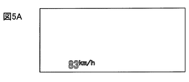
続いて、図5Aから図5Cの例について説明を行う。図5Aが固定属性表示であって、自車の車速を示す画像である。図5Bが移動属性表示であって、自車に接近する歩行者の存在を注意喚起するための警告マーカの画像である。図5Cが前景に図5A及び図5Bの画像が重畳表示される表示例を示した図である。図5CのViが投影領域を示している。図5Aから図5Cの例では、移動属性表示に緊急情報が含まれるので、移動属性表示のレイヤを上位層とする一方、固定属性表示のレイヤを下位層とし、固定属性表示のレイヤの上に移動属性表示のレイヤを重ねた画像が前景に重畳表示される。よって、警告マーカの画像が自車の車速を示す画像に上書きされたように見える表示が行われ、それぞれの画像がより区別しやすく表示されるとともに、警告マーカの画像がより見やすく表示される。
Subsequently, the example of FIGS. 5A to 5C will be described. FIG. 5A is a fixed attribute display, which is an image showing the speed of the host vehicle. FIG. 5B is a movement attribute display, which is an image of a warning marker for alerting the presence of a pedestrian approaching the vehicle. FIG. 5C is a diagram showing a display example in which the images of FIGS. 5A and 5B are superimposed and displayed on the foreground. Vi in FIG. 5C indicates a projection area. In the example of FIG. 5A to FIG. 5C, since the emergency information is included in the movement attribute display, the layer for the movement attribute display is set as the upper layer, while the layer for the fixed attribute display is set as the lower layer, An image on which layers of movement attribute display are superimposed is superimposed on the foreground. Therefore, a display is made in which the image of the warning marker appears to be overwritten on the image indicating the vehicle speed of the host vehicle, and the images of the warning marker are displayed in a more easily viewable manner while displaying each image in a more distinguishable manner.
なお、ここでは便宜上、移動属性表示のレイヤと固定属性表示のレイヤとがそれぞれ1つずつであるものとして説明を行うが、必ずしもこれに限らない。例えば、同じ移動属性表示であっても、表示項目の種類別にレイヤを分けたり、同じ固定属性表示であっても、表示項目の種類別にレイヤを分けたりする構成としてもよい。
In addition, here, for the sake of convenience, description will be made assuming that there is one moving attribute display layer and one fixed attribute display layer, but this is not necessarily the case. For example, the layers may be divided according to the type of display item even if they are the same movement attribute display, or the layers may be divided according to the type of display item even if they are the same fixed attribute display.
第1描画制御部211は、図3に示すように、第1輝度補正部212を有する。第1輝度補正部212は、室内明るさ取得部202で取得する自車の室内の照度に応じて固定属性表示の透過率を変化させることで、固定属性表示の見た目の輝度を変化させる。一例として、車両の室内の照度と、その車両のドライバからの視認性が一定以上となる固定属性表示の透過率との対応関係を参照し、自車の室内の照度に応じた、自車のドライバからの視認性が一定以上となる固定属性表示の透過率に変化させる構成とすればよい。なお、この対応関係は、シミュレーション,実験等によって求めたものを予めHCU20の不揮発性メモリに格納しておくことで、第1描画制御部211で利用可能とすればよい。主にドライバの近位側に表示される固定属性表示は、視認性を高めるために、自車の室内の照度に合わせて見た目の輝度を変化させる必要がある。以上の構成によれば、これに対し、自車の室内の照度に合わせて固定属性表示の見た目の輝度を変化させて視認性を高めることが可能になる。
The first drawing control unit 211 includes a first luminance correction unit 212 as shown in FIG. The first brightness correction unit 212 changes the apparent brightness of the fixed attribute display by changing the transmittance of the fixed attribute display according to the illuminance in the vehicle interior acquired by the room brightness acquisition unit 202. As an example, referring to the correspondence relationship between the illuminance in the vehicle interior and the transmittance of the fixed attribute display in which the visibility from the driver of the vehicle exceeds a certain level, What is necessary is just to set it as the structure changed to the transmittance | permeability of the fixed attribute display from which the visibility from a driver becomes more than fixed. Note that this correspondence relationship may be made available to the first drawing control unit 211 by storing in advance in the nonvolatile memory of the HCU 20 what is obtained by simulation, experiment, or the like. In the fixed attribute display mainly displayed on the proximal side of the driver, it is necessary to change the luminance of the appearance in accordance with the illuminance in the room of the own vehicle in order to improve the visibility. According to the above configuration, it is possible to improve the visibility by changing the apparent luminance of the fixed attribute display in accordance with the illuminance in the vehicle interior.
第2描画制御部213は、図3に示すように、第2輝度補正部214を有する。第2輝度補正部214は、前方明るさ取得部203で取得する自車の前方の照度に応じて移動属性表示の透過率を変化させることで、移動属性表示の見た目の輝度を変化させる。一例として、車両の前方の照度と、その車両のドライバからの視認性が一定以上となる移動属性表示の透過率との対応関係を参照し、自車の前方の照度に応じた、自車のドライバからの視認性が一定以上となる移動属性表示の透過率に変化させる構成とすればよい。なお、この対応関係は、シミュレーション,実験等によって求めたものを予めHCU20の不揮発性メモリに格納しておくことで、第2描画制御部213で利用可能とすればよい。ドライバの遠位側にまで表示され得る移動属性表示は、視認性を高めるために、自車の前方の照度に合わせて見た目の輝度を変化させる必要がある。以上の構成によれば、これに対し、自車の前方の照度に合わせて移動属性表示の見た目の輝度を変化させて視認性を高めることが可能になる。
The second drawing control unit 213 includes a second luminance correction unit 214 as shown in FIG. The second luminance correction unit 214 changes the apparent luminance of the movement attribute display by changing the transmittance of the movement attribute display according to the illuminance in front of the host vehicle acquired by the front brightness acquisition unit 203. As an example, referring to the correspondence between the illuminance in front of the vehicle and the transmissivity of the movement attribute display in which the visibility from the driver of the vehicle is more than a certain level, What is necessary is just to set it as the structure changed to the transmittance | permeability of the movement attribute display from which the visibility from a driver becomes more than fixed. Note that this correspondence relationship may be used by the second drawing control unit 213 by storing the correspondence obtained by simulation, experiment, or the like in advance in the nonvolatile memory of the HCU 20. In the movement attribute display that can be displayed to the far side of the driver, it is necessary to change the luminance of the appearance according to the illuminance in front of the host vehicle in order to improve the visibility. According to the above configuration, it is possible to improve visibility by changing the apparent luminance of the movement attribute display in accordance with the illuminance in front of the host vehicle.
なお、第1輝度補正部212及び第2輝度補正部214で表示画像の透過率を変化させるのは、固定属性表示を行うための表示器221と移動属性表示を行うための表示器221とが共通であってバックライトが共通であり、バックライトの輝度を固定属性表示と移動属性表示とで区別して切り替えることが困難なためである。
The first luminance correction unit 212 and the second luminance correction unit 214 change the transmittance of the display image by a display 221 for performing fixed attribute display and a display 221 for performing movement attribute display. This is because it is common and the backlight is common, and it is difficult to switch the brightness of the backlight separately between the fixed attribute display and the movement attribute display.
第1輝度補正部212及び第2輝度補正部214は、上位層になるレイヤの画像に対して下位層になるレイヤの表示画像の透過率を相対的に低くする。これにより、上位層になるレイヤの表示画像の視認性をより高めることが可能になる。第1輝度補正部212及び第2輝度補正部214は、上位層になるレイヤの表示画像の透過率を上げることで下位層になるレイヤの表示画像の透過率を相対的に低くする構成としてもよいし、下位層になるレイヤの表示画像の透過率を下げることで下位層になるレイヤの表示画像の透過率を相対的に低くする構成としてもよい。なお、下位層になるレイヤの表示画像の透過率を下げることで下位層になるレイヤの表示画像の透過率を相対的に低くすることがより好ましい。
The first luminance correction unit 212 and the second luminance correction unit 214 lower the transmittance of the display image of the lower layer relative to the upper layer image. Thereby, it becomes possible to further improve the visibility of the display image of the upper layer. The first luminance correction unit 212 and the second luminance correction unit 214 may be configured to relatively reduce the transmittance of the display image of the lower layer by increasing the transmittance of the display image of the upper layer. Alternatively, the transmittance of the display image of the lower layer may be relatively lowered by lowering the transmittance of the display image of the lower layer. It is more preferable that the transmittance of the display image of the lower layer is relatively lowered by lowering the transmittance of the display image of the lower layer.
第1輝度補正部212及び第2輝度補正部214は、前述の照度に応じた表示画像の透過率の範囲を満たすために上位層になるレイヤの画像の透過率を上げられない場合は、下位層になるレイヤの画像の透過率を下げることで、下位層になるレイヤの表示画像の透過率を相対的に低くすればよい。一方、前述の照度に応じた表示画像の透過率の範囲を満たすために下位層になるレイヤの画像の透過率を下げられない場合は、上位層になるレイヤの画像の透過率を上げることで、下位層になるレイヤの表示画像の透過率を相対的に低くすればよい。
If the first luminance correction unit 212 and the second luminance correction unit 214 cannot increase the transmittance of the upper layer image in order to satisfy the above-described transmittance range of the display image according to the illuminance, The transmittance of the display image of the lower layer may be relatively lowered by lowering the transmittance of the layer image. On the other hand, if the transmittance of the lower layer image cannot be reduced in order to satisfy the above-mentioned range of transmittance of the display image according to the illuminance, the transmittance of the upper layer image can be increased. The transmittance of the display image of the lower layer may be relatively lowered.
なお、第1輝度補正部212及び第2輝度補正部214は、前述の照度に応じた表示画像の透過率の範囲を満たすことと、上位層になるレイヤの画像に対して下位層になるレイヤの表示画像の透過率を相対的に低くすることとが両立できない場合には、以下のようにすればよい。例えば、移動属性表示のレイヤが上位層になる場合は、前述の照度に応じた表示画像の透過率の範囲を満たすことよりも、上位層になるレイヤの画像に対して下位層になるレイヤの表示画像の透過率を相対的に低くすることを優先すればよい。一方、固定属性表示のレイヤが上位層になる場合は、前述の照度に応じた表示画像の透過率の範囲を満たすことを、上位層になるレイヤの画像に対して下位層になるレイヤの表示画像の透過率を相対的に低くすることよりも優先すればよい。これによれば、緊急情報が含まれる移動属性表示の視認性を高めることを優先するといったように、必要に応じて表示画像の視認性を高めることが可能になる。
The first luminance correction unit 212 and the second luminance correction unit 214 satisfy the above-described transmittance range of the display image according to the illuminance, and are layers that are lower layers than images of layers that are upper layers. If it is not possible to achieve a relatively low transmittance of the display image, the following may be performed. For example, when the movement attribute display layer is an upper layer, the lower layer layer image is lower than the upper layer image, rather than satisfying the display image transmittance range according to the illuminance described above. What is necessary is just to give priority to making the transmittance | permeability of a display image relatively low. On the other hand, when the layer of fixed attribute display is the upper layer, the display of the layer that is the lower layer with respect to the image of the layer that is the upper layer is to meet the above-described transmittance range of the display image according to the illuminance What is necessary is just to give priority over lowering the transmittance of the image. According to this, it becomes possible to improve the visibility of the display image as necessary, such as giving priority to enhancing the visibility of the movement attribute display including the emergency information.
第2描画制御部213は、図3に示すように、さらに位置補正部215を有する。位置補正部215は、ピッチング情報取得部204で取得するピッチング情報をもとに、ピッチングによる前景に対する移動属性表示の虚像100の表示位置のずれを低減するように表示器221に描画する画像の描画位置を移動させる位置補正を行う。一例としては、表示位置のずれを補正するための補正関数が予めHCU20で設定されており、ピッチング情報取得部204で取得するピッチング情報をもとにこの補正関数を演算することで位置補正の補正値を算出する構成とすればよい。補正関数は、ピッチング情報と、前景に対する移動属性表示の虚像100の表示位置のずれを低減するための補正値との対応関係を示す関数である。位置補正部215は、算出する補正値に従って移動属性表示の描画位置を移動させることで位置補正を行う構成とすればよい。
The second drawing control unit 213 further includes a position correction unit 215 as shown in FIG. Based on the pitching information acquired by the pitching information acquisition unit 204, the position correction unit 215 draws an image to be drawn on the display unit 221 so as to reduce the shift in the display position of the virtual image 100 of the movement attribute display with respect to the foreground due to pitching. Perform position correction to move the position. As an example, a correction function for correcting a shift in display position is set in advance by the HCU 20, and correction of position correction is performed by calculating this correction function based on the pitching information acquired by the pitching information acquisition unit 204. What is necessary is just to set it as the structure which calculates a value. The correction function is a function indicating a correspondence relationship between the pitching information and a correction value for reducing the shift of the display position of the virtual image 100 of the movement attribute display with respect to the foreground. The position correction unit 215 may be configured to perform position correction by moving the drawing position of the movement attribute display according to the calculated correction value.
以上の構成によれば、自車のピッチングによる表示位置のずれを低減するように位置補正部215が位置補正を行うので、前景中の移動属性表示の対象に対する移動属性表示のずれを低減し、移動属性表示の意図がドライバに伝わり難くなることを防ぐことが可能になる。
According to the above configuration, since the position correction unit 215 performs position correction so as to reduce the shift of the display position due to the pitching of the own vehicle, the shift of the movement attribute display with respect to the target of the movement attribute display in the foreground is reduced, It is possible to prevent the intention of the movement attribute display from becoming difficult to be transmitted to the driver.
表示制御ブロック210では、ピッチング情報をもとにしたこの位置補正を、固定属性表示については行わない。つまり、第1描画制御部211では、ピッチング情報をもとに、ピッチングによる前景に対する固定属性表示の虚像100の表示位置のずれを低減するように表示器221に描画する画像の描画位置を移動させる位置補正を行わない。これは、固定属性表示は、前景中の対象に合わせて位置を変化させる表示画像でないため、ピッチングによる表示位置のずれを低減することよりも、位置補正によって表示画像の一部が投影領域から外れて欠けてしまうことを防ぐことを優先することが好ましいからである。
In the display control block 210, this position correction based on the pitching information is not performed for the fixed attribute display. That is, the first drawing control unit 211 moves the drawing position of the image drawn on the display 221 so as to reduce the shift of the display position of the virtual image 100 of the fixed attribute display with respect to the foreground due to the pitching based on the pitching information. Does not perform position correction. This is because the fixed attribute display is not a display image that changes its position according to the object in the foreground, and therefore, a part of the display image deviates from the projection area by position correction rather than reducing the display position shift due to pitching. This is because it is preferable to prioritize the prevention of chipping.
(HCU20での虚像表示制御関連処理)
続いて、図6のフローチャートを用いて、HCU20でのHUD装置220での表示の制御に関連する処理(以下、虚像表示制御関連処理)の流れの一例について説明を行う。図6のフローチャートは、HUD装置220の電源がオン且つHUD装置220の機能がオンになった場合に開始する構成とすればよい。HUD装置220の機能のオンオフは、操作デバイス21で受け付ける入力操作に応じて切り替えられる構成とすればよい。また、HUD装置220の電源のオンオフは、自車の内燃機関又はモータジェネレータを始動させるためのスイッチ(以下、パワースイッチ)のオンオフに応じて切り替えられる構成とすればよい。 (Virtual image display control related processing in HCU20)
Next, an example of the flow of processing related to display control in theHUD device 220 in the HCU 20 (hereinafter referred to as virtual image display control related processing) will be described using the flowchart of FIG. The flowchart in FIG. 6 may be configured to start when the power of the HUD device 220 is turned on and the function of the HUD device 220 is turned on. The function of the HUD device 220 may be switched on / off according to an input operation received by the operation device 21. The power supply of the HUD device 220 may be switched according to on / off of a switch (hereinafter referred to as a power switch) for starting the internal combustion engine or motor generator of the host vehicle.
続いて、図6のフローチャートを用いて、HCU20でのHUD装置220での表示の制御に関連する処理(以下、虚像表示制御関連処理)の流れの一例について説明を行う。図6のフローチャートは、HUD装置220の電源がオン且つHUD装置220の機能がオンになった場合に開始する構成とすればよい。HUD装置220の機能のオンオフは、操作デバイス21で受け付ける入力操作に応じて切り替えられる構成とすればよい。また、HUD装置220の電源のオンオフは、自車の内燃機関又はモータジェネレータを始動させるためのスイッチ(以下、パワースイッチ)のオンオフに応じて切り替えられる構成とすればよい。 (Virtual image display control related processing in HCU20)
Next, an example of the flow of processing related to display control in the
S1では、情報処理ブロック200の決定用情報取得部201、室内明るさ取得部202、前方明るさ取得部203、及びピッチング情報取得部204が、車内LANに出力された種々の情報のうちで、表示制御ブロック210での表示制御に必要な情報を選択的に取得する。
In S1, the determination information acquisition unit 201, the indoor brightness acquisition unit 202, the front brightness acquisition unit 203, and the pitching information acquisition unit 204 of the information processing block 200 are among the various information output to the in-vehicle LAN. Information necessary for display control in the display control block 210 is selectively acquired.
S2では、決定用情報取得部201で取得する情報のうちの移動属性表示用の情報に緊急情報が含まれる場合(S2でYES)には、S3に移る。一方、決定用情報取得部201で取得する情報のうちの移動属性表示用の情報に緊急情報が含まれない場合(S2でNO)には、S4に移る。
In S2, when the emergency information is included in the information for movement attribute display among the information acquired by the determination information acquisition unit 201 (YES in S2), the process proceeds to S3. On the other hand, when the emergency information is not included in the information for movement attribute display in the information acquired by the determination information acquisition unit 201 (NO in S2), the process proceeds to S4.
S3では、調停合成処理部216が、移動属性表示のレイヤを固定属性表示のレイヤよりも上位層のレイヤとし、S5に移る。一方、S4では、調停合成処理部216が、固定属性表示のレイヤを移動属性表示のレイヤよりも上位層のレイヤとし、S5に移る。
In S3, the arbitration composition processing unit 216 sets the movement attribute display layer as a higher layer than the fixed attribute display layer, and proceeds to S5. On the other hand, in S4, the arbitration composition processing unit 216 sets the fixed attribute display layer as a layer higher than the movement attribute display layer, and proceeds to S5.
S5では、S3で移動属性表示のレイヤを上位層とした場合には、第1輝度補正部212が固定属性表示のレイヤの表示画像の透過率を下げるか、若しくは第2輝度補正部214が移動属性表示のレイヤの表示画像の透過率を上げる。これにより、固定属性表示のレイヤの表示画像の透過率を移動属性表示のレイヤの表示画像の透過率に対して相対的に低くする。一方、S4で固定属性表示のレイヤを上位層とした場合には、第1輝度補正部212が固定属性表示のレイヤの表示画像の透過率を上げるか、若しくは第2輝度補正部214が移動属性表示のレイヤの表示画像の透過率を下げる。これにより、移動属性表示のレイヤの表示画像の透過率を固定属性表示のレイヤの表示画像の透過率に対して相対的に低くする。また、第1輝度補正部212は、室内明るさ取得部202で取得する自車の室内の照度に応じて固定属性表示の透過率を変化させ、第2輝度補正部214は、前方明るさ取得部203で取得する自車の前方の照度に応じて移動属性表示の透過率を変化させる。
In S5, when the movement attribute display layer is set as the upper layer in S3, the first luminance correction unit 212 lowers the transmittance of the display image of the fixed attribute display layer or the second luminance correction unit 214 moves. Increase the transmittance of the display image of the attribute display layer. Thereby, the transmittance of the display image of the layer with the fixed attribute display is made relatively lower than the transmittance of the display image of the layer with the movement attribute display. On the other hand, when the fixed attribute display layer is set as the upper layer in S4, the first luminance correction unit 212 increases the transmittance of the display image of the fixed attribute display layer, or the second luminance correction unit 214 sets the movement attribute. Decrease the transmittance of the display image of the display layer. Thereby, the transmittance of the display image of the layer with the movement attribute display is made relatively lower than the transmittance of the display image of the layer with the fixed attribute display. In addition, the first luminance correction unit 212 changes the transmittance of the fixed attribute display according to the illuminance in the vehicle interior acquired by the indoor brightness acquisition unit 202, and the second luminance correction unit 214 acquires the front brightness. The transmissivity of the movement attribute display is changed according to the illuminance ahead of the host vehicle acquired by the unit 203.
S6では、位置補正部215が、ピッチング情報取得部204で取得するピッチング情報をもとに移動属性表示の位置補正を行う。なお、S6の処理は、S5の処理の前に行う構成としてもよいし、S2の処理の前に行う構成としてもよい。
In S6, the position correction unit 215 corrects the position of the movement attribute display based on the pitching information acquired by the pitching information acquisition unit 204. The process of S6 may be performed before the process of S5, or may be performed before the process of S2.
S7では、調停合成処理部216が、第1描画制御部211及び第2描画制御部213に、上位層のレイヤを下位層のレイヤの上に重ね合わせて描画させる。例えば、移動属性表示のレイヤが上位層の場合には、移動属性表示のレイヤを固定属性表示のレイヤの上に重ね合わせて描画させる。一方、固定属性表示のレイヤが上位層の場合には、固定属性表示のレイヤを移動属性表示のレイヤの上に重ね合わせて描画させる。
In S7, the arbitration composition processing unit 216 causes the first drawing control unit 211 and the second drawing control unit 213 to draw the upper layer by overlapping the lower layer. For example, when the movement attribute display layer is an upper layer, the movement attribute display layer is drawn on top of the fixed attribute display layer. On the other hand, when the fixed attribute display layer is an upper layer, the fixed attribute display layer is drawn by being superimposed on the movement attribute display layer.
S8では、虚像表示制御関連処理の終了タイミングであった場合(S8でYES)には、虚像表示制御関連処理を終了する。一方、虚像表示制御関連処理の終了タイミングでなかった場合(S8でNO)には、S1に戻って処理を繰り返す。虚像表示制御関連処理の終了タイミングの一例としては、自車のパワースイッチがオフになった場合,HUD装置220の機能がオフになった場合等がある。
In S8, when it is the end timing of the virtual image display control related processing (YES in S8), the virtual image display control related processing is ended. On the other hand, if it is not the end timing of the virtual image display control related process (NO in S8), the process returns to S1 and the process is repeated. As an example of the end timing of the virtual image display control related processing, there is a case where the power switch of the own vehicle is turned off, a case where the function of the HUD device 220 is turned off, or the like.
実施形態1の構成によれば、HUD装置220の表示器221に画像を描画する際に、移動属性表示と固定属性表示とを異なるレイヤに分けて1つの表示器221に描画するので、移動属性表示と固定属性表示との虚像を車両の前景に複合的に表示させる場合であっても、双方を区別して表示することが可能になる。よって、双方の虚像が混ざり合うことによる双方の視認性の低下を抑えることが可能になる。その結果、フロントウインドシールド10といった投影部材へ画像を投影することによって車両といった移動体の前景に虚像100を重畳表示させる際に、移動属性の表示項目の画像と固定属性の表示項目の画像とを共通の投影部材へ投影して移動体の前景に双方の虚像を複合的に表示させる場合であっても、双方の虚像の視認性が低下することを抑えることが可能になる。
According to the configuration of the first embodiment, when an image is drawn on the display 221 of the HUD device 220, the movement attribute display and the fixed attribute display are divided into different layers and drawn on one display 221. Even when the virtual image of the display and the fixed attribute display is displayed in combination on the foreground of the vehicle, both can be displayed separately. Therefore, it is possible to suppress a reduction in both visibility due to a mixture of both virtual images. As a result, when the virtual image 100 is superimposed on the foreground of a moving body such as a vehicle by projecting an image onto a projection member such as the front windshield 10, an image of a moving attribute display item and an image of a fixed attribute display item are displayed. Even in a case where both virtual images are displayed on the foreground of the moving object by being projected onto a common projection member, the visibility of both virtual images can be prevented from being lowered.
実施形態1の構成によれば、移動属性表示と固定属性表示との透過率を変化させるので、移動属性表示と固定属性表示とを1つの表示器221で描画する場合であっても、それぞれの見た目の輝度を個別に切り替えることが容易に可能となる。さらに、実施形態1の構成によれば、移動属性表示と固定属性表示との透過率を別々に変化させる切り替えを行うことが可能であるので、双方の見た目の輝度を異ならせることができ、さらに双方を区別し易く表示することが可能になる。
According to the configuration of the first embodiment, the transmittance between the movement attribute display and the fixed attribute display is changed. Therefore, even when the movement attribute display and the fixed attribute display are drawn by one display 221, It is possible to easily switch the apparent luminance individually. Furthermore, according to the configuration of the first embodiment, since it is possible to perform switching for changing the transmittance between the movement attribute display and the fixed attribute display separately, it is possible to make the apparent luminance of both different, It is possible to display both of them easily.
(実施形態2)
実施形態1では、移動属性表示に緊急情報が含まれる場合には移動属性表示のレイヤを上位層とする一方、移動属性表示に緊急情報が含まれない場合には固定属性表示のレイヤを上位層とする構成を示したが、必ずしもこれに限らない。移動属性表示と固定属性表示とのいずれのレイヤを上位層とするかは、緊急情報以外の条件によって切り替える構成としてもよいし、条件にかかわらず固定であってもよい。この場合であっても、移動属性表示と固定属性表示とを異なるレイヤに分けさえすれば、双方を区別して表示することが可能になるので、双方の虚像が混ざり合うことによる双方の視認性の低下を抑えることが可能になる。 (Embodiment 2)
In the first embodiment, when the movement attribute display includes emergency information, the movement attribute display layer is set as the upper layer. When the movement attribute display does not include emergency information, the fixed attribute display layer is set as the upper layer. However, the present invention is not limited to this. Which layer of the movement attribute display and the fixed attribute display is set as the upper layer may be switched according to conditions other than the emergency information, or may be fixed regardless of the conditions. Even in this case, as long as the movement attribute display and the fixed attribute display are divided into different layers, it is possible to display both of them separately, so the visibility of both can be improved by mixing both virtual images. It becomes possible to suppress the decrease.
(実施形態3)
実施形態1では、第1輝度補正部212が、室内明るさ取得部202で取得する自車の室内の照度に応じて固定属性表示の透過率を変化させ、第2輝度補正部214が、前方明るさ取得部203で取得する自車の前方の照度に応じて移動属性表示の透過率を変化させる構成を示したが、必ずしもこれに限らない。例えば、HCU20が室内明るさ取得部202を備えず、自車の室内の照度に応じた固定属性表示の透過率の変化を行わせない構成であってもよい。また、HCU20が前方明るさ取得部203を備えず、自車の前方の照度に応じた移動属性表示の透過率の変化を行わせない構成であってもよい。 (Embodiment 3)
In the first embodiment, the firstluminance correction unit 212 changes the transmittance of the fixed attribute display according to the illuminance of the vehicle interior acquired by the indoor brightness acquisition unit 202, and the second luminance correction unit 214 Although the configuration in which the transmittance of the movement attribute display is changed according to the illuminance in front of the host vehicle acquired by the brightness acquisition unit 203 is shown, the configuration is not necessarily limited thereto. For example, the configuration may be such that the HCU 20 does not include the room brightness acquisition unit 202 and does not change the transmittance of the fixed attribute display according to the illuminance in the room of the host vehicle. Alternatively, the HCU 20 may not include the front brightness acquisition unit 203 and may not change the transmittance of the movement attribute display according to the illuminance ahead of the host vehicle.
実施形態1では、第1輝度補正部212が、室内明るさ取得部202で取得する自車の室内の照度に応じて固定属性表示の透過率を変化させ、第2輝度補正部214が、前方明るさ取得部203で取得する自車の前方の照度に応じて移動属性表示の透過率を変化させる構成を示したが、必ずしもこれに限らない。例えば、HCU20が室内明るさ取得部202を備えず、自車の室内の照度に応じた固定属性表示の透過率の変化を行わせない構成であってもよい。また、HCU20が前方明るさ取得部203を備えず、自車の前方の照度に応じた移動属性表示の透過率の変化を行わせない構成であってもよい。 (Embodiment 3)
In the first embodiment, the first
(実施形態4)
実施形態1では、第1輝度補正部212及び第2輝度補正部214が、上位層になるレイヤの画像に対して下位層になるレイヤの表示画像の透過率を相対的に低くする構成を示したが、必ずしもこれに限らない。例えば、第1輝度補正部212及び第2輝度補正部214が、上位層となるか下位層となるかにかかわらず、それぞれ室内明るさ取得部202で取得する自車の室内の照度,前方明るさ取得部203で取得する自車の前方の照度に応じて表示画像の透過率を変化させる構成としてもよい。 (Embodiment 4)
In the first embodiment, a configuration in which the firstluminance correction unit 212 and the second luminance correction unit 214 relatively reduce the transmittance of the display image of the lower layer with respect to the image of the upper layer is shown. However, this is not necessarily the case. For example, regardless of whether the first luminance correction unit 212 and the second luminance correction unit 214 are the upper layer or the lower layer, the illuminance and forward brightness of the vehicle interior acquired by the indoor brightness acquisition unit 202, respectively. It is good also as a structure which changes the transmittance | permeability of a display image according to the illumination intensity ahead of the own vehicle acquired by the length acquisition part 203. FIG.
実施形態1では、第1輝度補正部212及び第2輝度補正部214が、上位層になるレイヤの画像に対して下位層になるレイヤの表示画像の透過率を相対的に低くする構成を示したが、必ずしもこれに限らない。例えば、第1輝度補正部212及び第2輝度補正部214が、上位層となるか下位層となるかにかかわらず、それぞれ室内明るさ取得部202で取得する自車の室内の照度,前方明るさ取得部203で取得する自車の前方の照度に応じて表示画像の透過率を変化させる構成としてもよい。 (Embodiment 4)
In the first embodiment, a configuration in which the first
(実施形態5)
実施形態1では、位置補正部215が、ピッチング情報取得部204で取得するピッチング情報をもとに移動属性表示の位置補正を行う構成を示したが、必ずしもこれに限らない。例えば、HCU20がピッチング情報取得部204及び位置補正部215を備えず、移動属性表示の位置補正を行わない構成としてもよい。 (Embodiment 5)
In the first embodiment, theposition correction unit 215 performs the position correction of the movement attribute display based on the pitching information acquired by the pitching information acquisition unit 204. However, the configuration is not necessarily limited thereto. For example, the HCU 20 may not include the pitching information acquisition unit 204 and the position correction unit 215 and may not perform position correction of the movement attribute display.
実施形態1では、位置補正部215が、ピッチング情報取得部204で取得するピッチング情報をもとに移動属性表示の位置補正を行う構成を示したが、必ずしもこれに限らない。例えば、HCU20がピッチング情報取得部204及び位置補正部215を備えず、移動属性表示の位置補正を行わない構成としてもよい。 (Embodiment 5)
In the first embodiment, the
(実施形態6)
実施形態1では、自車が自動運転機能を有している場合に適用した例を挙げて説明を行ったが、必ずしもこれに限らない。例えば、自車が自動運転機能を有していない構成であってもよい。この場合には、移動体システム1に自動運転ECU8を含まず、走行環境の認識は他のECUで行うなどすればよい。 (Embodiment 6)
InEmbodiment 1, although the example applied when the own vehicle has an automatic driving function was given and demonstrated, it does not necessarily restrict to this. For example, the structure in which the own vehicle does not have an automatic driving function may be sufficient. In this case, the mobile system 1 does not include the automatic operation ECU 8, and the travel environment may be recognized by another ECU.
実施形態1では、自車が自動運転機能を有している場合に適用した例を挙げて説明を行ったが、必ずしもこれに限らない。例えば、自車が自動運転機能を有していない構成であってもよい。この場合には、移動体システム1に自動運転ECU8を含まず、走行環境の認識は他のECUで行うなどすればよい。 (Embodiment 6)
In
(実施形態7)
実施形態1では、HUD装置220での表示の制御に関する機能をHUD装置220とは別体のHCU20が担う構成を示したが、必ずしもこれに限らない。例えば、HUD装置220での表示の制御に関する機能をHUD装置220に設けられる制御回路が担う構成としてもよいし、コンビネーションメータに設けられる制御回路等が担う構成としてもよい。 (Embodiment 7)
In the first embodiment, the configuration in which theHCU 20 separate from the HUD device 220 performs the function related to the display control in the HUD device 220 is shown, but the configuration is not necessarily limited thereto. For example, the control circuit provided in the HUD device 220 may be responsible for functions related to display control in the HUD device 220, or may be configured as the control circuit provided in the combination meter.
実施形態1では、HUD装置220での表示の制御に関する機能をHUD装置220とは別体のHCU20が担う構成を示したが、必ずしもこれに限らない。例えば、HUD装置220での表示の制御に関する機能をHUD装置220に設けられる制御回路が担う構成としてもよいし、コンビネーションメータに設けられる制御回路等が担う構成としてもよい。 (Embodiment 7)
In the first embodiment, the configuration in which the
本開示に記載の制御及びその手法は、コンピュータプログラムにより具体化された一つ乃至は複数の機能を実行するようにプログラムされたプロセッサを構成する専用コンピュータにより、実現されてもよい。あるいは、本開示に記載の制御及びその手法は、専用ハードウェア論理回路によってプロセッサを構成する専用コンピュータにより、実現されてもよい。もしくは、本開示に記載の制御及びその手法は、コンピュータプログラムを実行するプロセッサと一つ以上のハードウェア論理回路との組み合わせにより構成された一つ以上の専用コンピュータにより、実現されてもよい。また、コンピュータプログラムは、コンピュータにより実行されるインストラクションとして、コンピュータ読み取り可能な非遷移有形記録媒体に記憶されていてもよい。
The control and the method described in the present disclosure may be realized by a dedicated computer constituting a processor programmed to execute one or a plurality of functions embodied by a computer program. Alternatively, the control and the method thereof described in the present disclosure may be realized by a dedicated computer that configures a processor with a dedicated hardware logic circuit. Alternatively, the control and the method described in the present disclosure may be realized by one or more dedicated computers configured by a combination of a processor that executes a computer program and one or more hardware logic circuits. The computer program may be stored in a computer-readable non-transition tangible recording medium as instructions executed by the computer.
ここで本願に記載されるフローチャート、あるいは、フローチャートの処理は、複数のステップ(あるいはセクションと言及される)から構成され、各ステップは、たとえば、S1と表現される。さらに、各ステップは、複数のサブステップに分割されることができる、一方、複数のステップが合わさって一つのステップにすることも可能である。
Here, the flowchart described in the present application or the process of the flowchart is composed of a plurality of steps (or referred to as sections), and each step is expressed as, for example, S1. Further, each step can be divided into a plurality of sub-steps, while a plurality of steps can be combined into one step.
以上、本開示の一態様に係る移動体用表示制御装置、移動体用表示制御方法および制御プログラムの実施形態、構成、態様を例示したが、本開示に係る実施形態、構成、態様は、上述した各実施形態、各構成、各態様に限定されるものではない。例えば、異なる実施形態、構成、態様にそれぞれ開示された技術的部を適宜組み合わせて得られる実施形態、構成、態様についても本開示に係る実施形態、構成、態様の範囲に含まれる。
Heretofore, the embodiment, configuration, and aspect of the display control device for mobile body, the display control method for mobile body, and the control program according to one aspect of the present disclosure have been exemplified, but the embodiment, configuration, and aspect according to the present disclosure are described above. However, the present invention is not limited to each embodiment, each configuration, and each aspect. For example, embodiments, configurations, and aspects obtained by appropriately combining technical parts disclosed in different embodiments, configurations, and aspects are also included in the scope of the embodiments, configurations, and aspects according to the present disclosure.
Heretofore, the embodiment, configuration, and aspect of the display control device for mobile body, the display control method for mobile body, and the control program according to one aspect of the present disclosure have been exemplified, but the embodiment, configuration, and aspect according to the present disclosure are described above. However, the present invention is not limited to each embodiment, each configuration, and each aspect. For example, embodiments, configurations, and aspects obtained by appropriately combining technical parts disclosed in different embodiments, configurations, and aspects are also included in the scope of the embodiments, configurations, and aspects according to the present disclosure.
Claims (10)
- 移動体で用いられ、表示器に描画する画像を投影部材へ投影することによって前記移動体の前景に虚像を重畳表示させるヘッドアップディスプレイ装置を制御する移動体用表示制御装置であって、
前記表示器に描画する画像の内容を定めるための情報である内容決定用情報を取得する決定用情報取得部(201)と、
前記決定用情報取得部で取得する前記内容決定用情報に応じて前記表示器に画像を描画する描画制御部(211,213)とを備え、
前記描画制御部は、重畳表示させる前記前景中の対象に合わせて位置を変化させる移動属性の画像と、前記前景にかかわらず位置が定まっている固定属性の画像とを異なるレイヤに分けて1つの表示器に描画する移動体用表示制御装置。 A display control device for a moving body that controls a head-up display device that is used in a moving body and displays a virtual image superimposed on the foreground of the moving body by projecting an image to be drawn on a display device onto a projection member,
A determination information acquisition unit (201) that acquires content determination information that is information for determining the content of an image to be drawn on the display;
A drawing control unit (211, 213) for drawing an image on the display unit according to the content determination information acquired by the determination information acquisition unit;
The drawing control unit divides a moving attribute image whose position is changed according to a target in the foreground to be superimposed and a fixed attribute image whose position is fixed regardless of the foreground into different layers, and A display control device for a moving body that draws on a display. - 前記移動属性の画像に前記移動体のユーザが緊急に対応すべき緊急情報が含まれる場合には、前記移動属性の画像のレイヤが、前記固定属性の画像よりも上位層に表示されるレイヤとなる請求項1に記載の移動体用表示制御装置。 When the moving attribute image includes emergency information that the user of the moving body should respond urgently, the layer of the moving attribute image is displayed on a layer higher than the fixed attribute image; The display control apparatus for moving bodies according to claim 1.
- 前記移動属性の画像に前記緊急情報が含まれない場合には、前記固定属性の画像のレイヤが、前記移動属性の画像よりも上位層に表示されるレイヤとなる請求項2に記載の移動体用表示制御装置。 The mobile object according to claim 2, wherein, when the emergency information is not included in the movement attribute image, the layer of the fixed attribute image is a layer displayed in a higher layer than the movement attribute image. Display controller.
- 前記描画制御部は、前記移動属性の画像のレイヤと、前記固定属性の画像のレイヤとで、描画する画像の透過率を切り替えて描画することが可能な請求項1~3のいずれか1項に記載の移動体用表示制御装置。 4. The drawing control unit according to any one of claims 1 to 3, wherein the drawing control unit can perform drawing by switching a transmittance of an image to be drawn between the image layer having the movement attribute and the image layer having the fixed attribute. The display control apparatus for moving bodies described in 1.
- 前記移動体の室内の明るさを取得する室内明るさ取得部(202)と、
前記移動体の前方の明るさを取得する前方明るさ取得部(203)とを備え、
前記描画制御部は、前記室内明るさ取得部で取得する前記移動体の室内の明るさに応じて、前記固定属性の画像のレイヤに描画する画像の透過率を変化させる一方、前記前方明るさ取得部で取得する前記移動体の前方の明るさに応じて、前記移動属性の画像のレイヤに描画する画像の透過率を変化させる請求項4に記載の移動体用表示制御装置。 An indoor brightness acquisition unit (202) for acquiring the indoor brightness of the mobile body;
A front brightness acquisition unit (203) that acquires the brightness of the front of the moving body,
The drawing control unit changes the transmittance of the image to be drawn on the image layer of the fixed attribute according to the indoor brightness of the moving body acquired by the indoor brightness acquisition unit, while the front brightness The display control apparatus for a moving body according to claim 4, wherein the transmittance of the image drawn on the layer of the image of the movement attribute is changed according to the brightness in front of the moving body acquired by the acquisition unit. - 前記描画制御部は、前記移動属性の画像のレイヤと、前記固定属性の画像のレイヤとのうち、上位層とするレイヤの画像に対して下位層とするレイヤの画像の透過率を相対的に下げて描画する請求項4又は5に記載の移動体用表示制御装置。 The drawing control unit relatively sets the transmittance of the lower layer image relative to the upper layer image of the movement attribute image layer and the fixed attribute image layer relative to each other. The display control apparatus for a moving body according to claim 4 or 5, wherein the display control apparatus for drawing is lowered.
- 前記移動体のピッチングの状態を示すピッチング情報を取得するピッチング情報取得部(204)を備え、
前記描画制御部は、前記ピッチング情報取得部で取得する前記ピッチング情報をもとに、前記ピッチングによる前記前景に対する前記虚像の表示位置のずれを低減するように前記表示器に描画する画像の描画位置を移動させる位置補正を行う位置補正部(215)を有し、
前記固定属性の画像のレイヤに描画する画像については、前記位置補正部での前記位置補正を行わない一方、前記移動属性の画像のレイヤに描画する画像については、前記位置補正部での前記位置補正を行う請求項1~6のいずれか1項に記載の移動体用表示制御装置。 A pitching information acquisition unit (204) for acquiring pitching information indicating a pitching state of the mobile body;
The drawing control unit, based on the pitching information acquired by the pitching information acquisition unit, draws an image to be drawn on the display so as to reduce a shift in the display position of the virtual image with respect to the foreground due to the pitching A position correction unit (215) for performing position correction for moving
The position correction unit does not perform the position correction on the image drawn on the fixed attribute image layer, while the position correction unit does not perform the position correction on the movement attribute image layer. The display control apparatus for a moving body according to any one of claims 1 to 6, wherein correction is performed. - 移動体で用いられ、表示器に描画する画像を投影部材へ投影することによって前記移動体の前景に虚像を重畳表示させるヘッドアップディスプレイ装置を制御する移動体用表示制御方法であって、
前記表示器に描画する画像の内容を定めるための情報である内容決定用情報を取得し、
取得する前記内容決定用情報に応じて前記表示器に画像を描画する際に、重畳表示させる前記前景中の対象に合わせて位置を変化させる移動属性の画像と、前記前景にかかわらず位置が定まっている固定属性の画像とを異なるレイヤに分けて1つの表示器に描画する移動体用表示制御方法。 A moving body display control method for controlling a head-up display device that is used in a moving body and projects a virtual image superimposed on the foreground of the moving body by projecting an image to be drawn on a display device onto a projection member,
Obtaining information for determining content that is information for determining the content of an image to be drawn on the display,
When drawing an image on the display according to the content determination information to be acquired, the position of the moving attribute is changed regardless of the foreground, and the image has a movement attribute that changes the position according to the object in the foreground to be superimposed. A display control method for a moving object, in which an image having a fixed attribute is divided into different layers and drawn on a single display. - コンピュータを、
移動体で用いられ、表示器に描画する画像を投影部材へ投影することによって前記移動体の前景に虚像を重畳表示させるヘッドアップディスプレイ装置の前記表示器に描画する画像の内容を定めるための情報である内容決定用情報を取得する決定用情報取得部(201)と、
前記決定用情報取得部で取得する前記内容決定用情報に応じて前記表示器に画像を描画する際に、重畳表示させる前記前景中の対象に合わせて位置を変化させる移動属性の画像と、前記前景にかかわらず位置が定まっている固定属性の画像とを異なるレイヤに分けて1つの表示器に描画する描画制御部(211,213)として機能させるための制御プログラム。 Computer
Information used to determine the content of an image to be drawn on the display of a head-up display device that is used by the moving body and projects a virtual image superimposed on the foreground of the moving body by projecting the image to be drawn on the display onto a projection member A determination information acquisition unit (201) for acquiring content determination information,
When rendering an image on the display unit according to the content determination information acquired by the determination information acquisition unit, an image of a movement attribute that changes a position according to an object in the foreground to be superimposed and displayed, A control program for functioning as a drawing control unit (211, 213) that divides a fixed attribute image whose position is fixed regardless of the foreground into different layers and draws it on one display device. - 請求項9に記載の制御プログラムを記憶する、コンピュータ読み取り可能な非遷移的実体的記憶媒体。
A computer-readable non-transitional tangible storage medium storing the control program according to claim 9.
Applications Claiming Priority (2)
| Application Number | Priority Date | Filing Date | Title |
|---|---|---|---|
| JP2018-112068 | 2018-06-12 | ||
| JP2018112068A JP7024619B2 (en) | 2018-06-12 | 2018-06-12 | Display control device for mobile body, display control method for mobile body, and control program |
Publications (1)
| Publication Number | Publication Date |
|---|---|
| WO2019239709A1 true WO2019239709A1 (en) | 2019-12-19 |
Family
ID=68843119
Family Applications (1)
| Application Number | Title | Priority Date | Filing Date |
|---|---|---|---|
| PCT/JP2019/016112 WO2019239709A1 (en) | 2018-06-12 | 2019-04-15 | Moving body display control device, moving body display control method, and control program |
Country Status (2)
| Country | Link |
|---|---|
| JP (1) | JP7024619B2 (en) |
| WO (1) | WO2019239709A1 (en) |
Families Citing this family (2)
| Publication number | Priority date | Publication date | Assignee | Title |
|---|---|---|---|---|
| US11878712B2 (en) | 2020-02-26 | 2024-01-23 | Baidu Usa Llc | Trajectory planning with obstacle avoidance for autonomous driving vehicles |
| CN113984087A (en) * | 2021-11-08 | 2022-01-28 | 维沃移动通信有限公司 | Navigation method, navigation device, electronic equipment and readable storage medium |
Citations (5)
| Publication number | Priority date | Publication date | Assignee | Title |
|---|---|---|---|---|
| JP2009053539A (en) * | 2007-08-28 | 2009-03-12 | Sony Corp | Information display device, information display method, and program |
| WO2016051586A1 (en) * | 2014-10-03 | 2016-04-07 | 三菱電機株式会社 | Display control device |
| JP2017013590A (en) * | 2015-06-30 | 2017-01-19 | 日本精機株式会社 | Head-up display device |
| JP2017081428A (en) * | 2015-10-28 | 2017-05-18 | 日本精機株式会社 | Vehicle display device |
| JP2018022105A (en) * | 2016-08-05 | 2018-02-08 | パナソニックIpマネジメント株式会社 | Head-up display device, display control method, and control program |
Family Cites Families (1)
| Publication number | Priority date | Publication date | Assignee | Title |
|---|---|---|---|---|
| KR101899981B1 (en) | 2016-12-02 | 2018-09-19 | 엘지전자 주식회사 | Head Up Display for Vehicle |
-
2018
- 2018-06-12 JP JP2018112068A patent/JP7024619B2/en active Active
-
2019
- 2019-04-15 WO PCT/JP2019/016112 patent/WO2019239709A1/en active Application Filing
Patent Citations (5)
| Publication number | Priority date | Publication date | Assignee | Title |
|---|---|---|---|---|
| JP2009053539A (en) * | 2007-08-28 | 2009-03-12 | Sony Corp | Information display device, information display method, and program |
| WO2016051586A1 (en) * | 2014-10-03 | 2016-04-07 | 三菱電機株式会社 | Display control device |
| JP2017013590A (en) * | 2015-06-30 | 2017-01-19 | 日本精機株式会社 | Head-up display device |
| JP2017081428A (en) * | 2015-10-28 | 2017-05-18 | 日本精機株式会社 | Vehicle display device |
| JP2018022105A (en) * | 2016-08-05 | 2018-02-08 | パナソニックIpマネジメント株式会社 | Head-up display device, display control method, and control program |
Also Published As
| Publication number | Publication date |
|---|---|
| JP2019214273A (en) | 2019-12-19 |
| JP7024619B2 (en) | 2022-02-24 |
Similar Documents
| Publication | Publication Date | Title |
|---|---|---|
| US10362230B2 (en) | In-vehicle display device | |
| US10254539B2 (en) | On-vehicle device, method of controlling on-vehicle device, and computer-readable storage medium | |
| WO2018159119A1 (en) | Display control device and display control method | |
| US10452930B2 (en) | Information display device mounted in vehicle including detector | |
| JP6969509B2 (en) | Vehicle display control device, vehicle display control method, and control program | |
| CN111034186B (en) | Surrounding vehicle display method and surrounding vehicle display device | |
| US11200806B2 (en) | Display device, display control method, and storage medium | |
| US20230191911A1 (en) | Vehicle display apparatus | |
| WO2020162109A1 (en) | Display control device, display control program, and persistent physical computer-readable medium | |
| WO2020189238A1 (en) | Vehicular display control device, vehicular display control method, and vehicular display control program | |
| US11274934B2 (en) | Information output device, output control method, and storage medium | |
| WO2019239709A1 (en) | Moving body display control device, moving body display control method, and control program | |
| US11214197B2 (en) | Vehicle surrounding area monitoring device, vehicle surrounding area monitoring method, vehicle, and storage medium storing program for the vehicle surrounding area monitoring device | |
| JP7400242B2 (en) | Vehicle display control device and vehicle display control method | |
| WO2018173512A1 (en) | Display control device for vehicle and display unit for vehicle | |
| JP2019039883A (en) | Vehicle display device and display control method | |
| JP2023003663A (en) | Virtual image display device | |
| WO2020246114A1 (en) | Display control device and display control program | |
| JP7310851B2 (en) | vehicle display | |
| JP7206867B2 (en) | Display controller and display control program | |
| WO2022210171A1 (en) | Vehicle display system, vehicle display method, and vehicle display program | |
| US20240101138A1 (en) | Display system | |
| WO2019220884A1 (en) | Driving assistance device | |
| JP7172730B2 (en) | Vehicle display control device, vehicle display control method, vehicle display control program | |
| WO2020121810A1 (en) | Display control device, display control program, and tangible, non-transitory computer-readable recording medium |
Legal Events
| Date | Code | Title | Description |
|---|---|---|---|
| 121 | Ep: the epo has been informed by wipo that ep was designated in this application |
Ref document number: 19820515 Country of ref document: EP Kind code of ref document: A1 |
|
| NENP | Non-entry into the national phase |
Ref country code: DE |
|
| 122 | Ep: pct application non-entry in european phase |
Ref document number: 19820515 Country of ref document: EP Kind code of ref document: A1 |