WO2019239473A1 - 制御システム、空気調和機およびサーバ - Google Patents
制御システム、空気調和機およびサーバ Download PDFInfo
- Publication number
- WO2019239473A1 WO2019239473A1 PCT/JP2018/022287 JP2018022287W WO2019239473A1 WO 2019239473 A1 WO2019239473 A1 WO 2019239473A1 JP 2018022287 W JP2018022287 W JP 2018022287W WO 2019239473 A1 WO2019239473 A1 WO 2019239473A1
- Authority
- WO
- WIPO (PCT)
- Prior art keywords
- air conditioner
- information
- attribute
- user
- unit
- Prior art date
- Legal status (The legal status is an assumption and is not a legal conclusion. Google has not performed a legal analysis and makes no representation as to the accuracy of the status listed.)
- Ceased
Links
Images











Classifications
-
- F—MECHANICAL ENGINEERING; LIGHTING; HEATING; WEAPONS; BLASTING
- F24—HEATING; RANGES; VENTILATING
- F24F—AIR-CONDITIONING; AIR-HUMIDIFICATION; VENTILATION; USE OF AIR CURRENTS FOR SCREENING
- F24F11/00—Control or safety arrangements
- F24F11/50—Control or safety arrangements characterised by user interfaces or communication
- F24F11/54—Control or safety arrangements characterised by user interfaces or communication using one central controller connected to several sub-controllers
Definitions
- the present invention relates to a control system, an air conditioner, and a server.
- each energy consuming device periodically receives an average value derived with respect to the control value of the energy consuming device having the same user attribute, and is set based on the user's selection. According to the operation mode, the control value of each energy consuming device is changed by a certain amount with respect to the received average value.
- an image sensor is installed in each energy consuming device, and the attributes of the user of each energy consuming device are specified from the captured image obtained by the image sensor using image recognition technology. Can be considered. However, in that case, a high-sensitivity image sensor must be mounted on all energy consuming devices. In other words, all energy consuming equipment must be unified into a high-performance model.
- HEMS Home Energy Management System
- the present invention aims to reduce the trouble of registering attribute information while allowing a mixture of a low-functional model and a high-functional model.
- a control system includes: An attribute input unit to which attribute information indicating an attribute of the first user who uses the first air conditioner is input; An information acquisition unit for acquiring operation information obtained during operation by a second air conditioner different from the first air conditioner; The attribute indicated in the attribute information input to the attribute input unit, and the attribute of the second user using the second air conditioner specified from the data collected by the second air conditioner.
- an operation control unit that controls the operation of the first air conditioner based on the operation information acquired by the information acquisition unit is provided.
- the operation of the first air conditioner is the operation of the second air conditioner. Control based on information.
- a 2nd air conditioner since a user's attribute is specified from the collected data, the effort of registration of attribute information can be saved.
- a 1st air conditioner since a user's attribute is specified from the input information, a lower function model than a 2nd air conditioner can be applied to a 1st air conditioner. Therefore, according to the present invention, it is possible to reduce the trouble of registering attribute information while allowing a mixture of a low-functional model and a high-functional model to be allowed.
- FIG. 1 is a block diagram showing a configuration of a control system according to Embodiment 1.
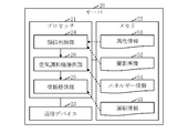
- FIG. FIG. 2 is a block diagram illustrating a configuration of a server according to the first embodiment.
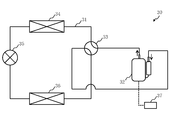
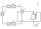
- FIG. 3 is a circuit diagram illustrating a configuration of the air conditioner according to Embodiment 1.
- FIG. 3 is a circuit diagram illustrating a configuration of the air conditioner according to Embodiment 1.
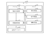
- FIG. 2 is a block diagram showing a configuration of a first controller of the first air conditioner according to Embodiment 1.
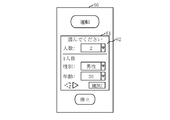
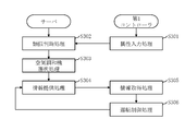
- 3 is a flowchart showing the operation of the control system according to the first embodiment. The figure which shows the example of a screen of the remote controller of the 1st air conditioner which concerns on Embodiment 1.
- FIG. 7 is a flowchart showing the operation of the control system according to the second embodiment.
- FIG. 4 is a block diagram showing a configuration of a server according to Embodiment 3.
- 10 is a flowchart showing the operation of the control system according to the third embodiment.
- FIG. 6 is a block diagram showing a configuration of a control system according to a fourth embodiment.
- FIG. 6 is a block diagram showing a configuration of a server according to Embodiment 4.
- 10 is a flowchart showing the operation of a control system according to the fourth embodiment. The figure which shows the example of a screen of the remote controller of the 1st air conditioner which concerns on Embodiment 4.
- FIG. 6 is a block diagram showing a configuration of a control system according to a fourth embodiment.
- FIG. 6 is a block diagram showing a configuration of a server according to Embodiment 4.
- 10 is a flowchart showing the operation of a control system according to the fourth embodiment. The figure which shows the example of a screen of the remote controller of the 1st air conditioner which concerns on Embodiment 4.
- Embodiment 1 FIG. This embodiment will be described with reference to FIGS.
- the control system 10 includes a server 20 and a large number of air conditioners 30 that can communicate with the server 20 via a network 11 such as the Internet.
- Each air conditioner 30 is either the first air conditioner 30a or the second air conditioner 30b.
- the second air conditioner 30b is a model with higher functionality than the first air conditioner 30a.
- the second air conditioner 30b is a model in which the image sensor 38b is mounted
- the first air conditioner 30a is a model in which the image sensor 38a is not mounted
- the second air conditioner has a lower sensitivity than the image sensor 38b mounted on the machine 30b.
- a model without an image sensor is a low-priced standard model
- a model with an image sensor 38a is a medium-priced medium model
- a model with an image sensor 38b is a deluxe model of high price range.
- the image sensor 38a mounted on the first air conditioner 30a is an infrared sensor in the present embodiment, but may be a camera.
- the image sensor 38b mounted on the second air conditioner 30b is an infrared sensor having a higher resolution than the image sensor 38a in the present embodiment, but may be a camera.
- the configuration of the server 20 will be described with reference to FIG.
- the server 20 is a computer. Specifically, the server 20 is a server computer provided in the cloud system.
- the server 20 includes a processor 21 and other hardware such as a memory 22 and a communication device 23.
- the processor 21 is connected to other hardware via a signal line, and controls these other hardware.
- the server 20 includes a similarity determination unit 24 and an information providing unit 25 as functional elements.
- the functions of the similarity determining unit 24 and the information providing unit 25 are realized by software.
- the functions of the similarity determining unit 24 and the information providing unit 25 are realized by a server program.
- the server program is a program that causes a computer to execute processes performed by the similarity determination unit 24 and the information providing unit 25 as a similarity determination process and an information providing process, respectively.
- the server program may be provided by being recorded on a computer-readable medium, may be provided by being stored in a recording medium, or may be provided as a program product.
- the processor 21 is a device that executes a server program.
- the processor 21 is, for example, a CPU.
- CPU Central Processing Unit
- the memory 22 is a device that stores a server program.
- the memory 22 is, for example, a RAM, a flash memory, or a combination thereof.
- RAM is an abbreviation for Random Access Memory.
- the memory 22 stores attribute information 51, a captured image 52, and driving information 53.
- the attribute information 51 is information indicating the attribute of the first user U1 who uses the first air conditioner 30a.
- the attribute information 51 is information indicating attributes such as the sex, age, and family structure of the first user U1.
- lifestyles be recognized as attributes.
- the first user U1 is a two-person household of males in their 30s and females in their 30s, it is desirable to recognize whether the household is a dual-income household without children.
- An action pattern such as when to wake up, go out, go home, take a bath, go to bed may be recognized as an attribute.
- a preference such as hot or cold may be recognized as an attribute.
- the attribute information 51 is input to the first air conditioner 30a by the first user U1 in the present embodiment.
- the attribute information 51 is first input by a third party other than the first user U1, such as an installer of the first air conditioner 30a. It may be input to the air conditioner 30a.
- the attribute information 51 may be acquired from an arbitrary information source through an arbitrary route. In the present embodiment, the attribute information 51 is acquired directly from the first air conditioner 30 a via the network 11.
- the photographed image 52 is an image obtained by the image sensor 38b mounted on the second air conditioner 30b. Specifically, the photographed image 52 is an image obtained by photographing the inside of a building such as a house where the indoor unit of the second air conditioner 30b is installed.
- the captured image 52 may be acquired from an arbitrary information source through an arbitrary route, but in the present embodiment, the captured image 52 is acquired directly from the second air conditioner 30 b via the network 11.
- the operation information 53 is information obtained during operation by the second air conditioner 30b.
- the operation information 53 is information indicating the operation mode of the second air conditioner 30b.
- the operation mode is, for example, a cooling operation, a heating operation, a blowing operation, an air cleaning operation, a humidifying operation, or a dehumidifying operation.
- the operation information 53 may include various data related to the operation of the second air conditioner 30b, such as the capability of the second air conditioner 30b, the compressor rotation speed, and the fan rotation speed.
- the operation information 53 may be acquired from an arbitrary information source through an arbitrary route, but in the present embodiment, it is acquired directly from the second air conditioner 30 b via the network 11.
- the communication device 23 includes a receiver that receives data input to the server program and a transmitter that transmits data output from the server program.
- the communication device 23 is, for example, a communication chip or a NIC.
- NIC is an abbreviation for Network Interface Card.
- the server program is read from the memory 22 into the processor 21 and executed by the processor 21.
- the memory 22 stores the OS as well as the server program.
- OS is an abbreviation for Operating System.
- the processor 21 executes the server program while executing the OS. A part or all of the server program may be incorporated in the OS.
- the server program and the OS may be stored in an auxiliary storage device.
- the auxiliary storage device is, for example, an HDD, a flash memory, or a combination thereof. “HDD” is an abbreviation for Hard Disk Drive.
- the server 20 may include a plurality of processors that replace the processor 21.
- the plurality of processors share the execution of the server program.
- Each processor is, for example, a CPU.
- Data, information, signal values and variable values used, processed or output by the server program are stored in the memory 22, the auxiliary storage device, or a register or cache memory in the processor 21.
- the server 20 may be composed of a single computer or a plurality of computers.
- the functions of the similarity determination unit 24 and the information providing unit 25 may be realized by being distributed to each computer.
- each air conditioner 30 will be described with reference to FIGS.
- FIG. 3 shows the refrigerant circuit 31 during the cooling operation.
- FIG. 4 shows the refrigerant circuit 31 during heating operation.
- Each air conditioner 30 includes a refrigerant circuit 31 in which the refrigerant circulates.
- Each air conditioner 30 includes a compressor 32, a four-way valve 33, a first heat exchanger 34 that is an outdoor heat exchanger, an expansion mechanism 35 that is an expansion valve, and a second heat exchange that is an indoor heat exchanger. And a device 36.
- the compressor 32, the four-way valve 33, the first heat exchanger 34, the expansion mechanism 35, and the second heat exchanger 36 are connected to the refrigerant circuit 31.
- Compressor 32 compresses the refrigerant.
- the four-way valve 33 switches the direction in which the refrigerant flows between the cooling operation and the heating operation.
- the first heat exchanger 34 operates as a condenser during the cooling operation, and radiates the refrigerant compressed by the compressor 32. That is, the first heat exchanger 34 performs heat exchange using the refrigerant compressed by the compressor 32.
- the first heat exchanger 34 operates as an evaporator during the heating operation, and heats the refrigerant by exchanging heat between the outdoor air and the refrigerant expanded by the expansion mechanism 35.
- the expansion mechanism 35 expands the refrigerant radiated by the condenser.
- the second heat exchanger 36 operates as a condenser during the heating operation, and dissipates the refrigerant compressed by the compressor 32. That is, the second heat exchanger 36 performs heat exchange using the refrigerant compressed by the compressor 32.
- the second heat exchanger 36 operates as an evaporator during the cooling operation, and heats the refrigerant by exchanging heat between the indoor air and the refrigerant expanded by the expansion mechanism 35.
- Each air conditioner 30 further includes a controller 37.
- controller 37 is connected not only to the compressor 32 but also to components other than the compressor 32 connected to the refrigerant circuit 31. May be.
- the controller 37 monitors and controls the state of each component connected to the controller 37.
- the first controller 40 is a computer. Specifically, the first controller 40 is a microcomputer.
- the first controller 40 includes a processor 41 and other hardware such as a memory 42 and a communication device 43.
- the processor 41 is connected to other hardware via a signal line, and controls these other hardware.
- the first controller 40 includes an attribute input unit 44, an information acquisition unit 45, and an operation control unit 46 as functional elements.
- the functions of the attribute input unit 44, the information acquisition unit 45, and the operation control unit 46 are realized by software. Specifically, the functions of the attribute input unit 44, the information acquisition unit 45, and the operation control unit 46 are realized by a control program.
- the control program is a program that causes the computer to execute processes performed by the attribute input unit 44, the information acquisition unit 45, and the operation control unit 46 as an attribute input process, an information acquisition process, and an operation control process, respectively.
- the control program may be provided by being recorded on a computer-readable medium, may be provided by being stored in a recording medium, or may be provided as a program product.
- the processor 41 is a device that executes a control program.
- the processor 41 is, for example, a CPU.
- the memory 42 is a device that stores a control program.
- the memory 42 is, for example, a RAM, a flash memory, or a combination thereof.
- the memory 42 stores the attribute information 51 and the operation information 53 described above.
- the communication device 43 includes a receiver that receives data input to the control program and a transmitter that transmits data output from the control program.
- the communication device 43 is, for example, a communication chip or a NIC.
- the control program is read from the memory 42 into the processor 41 and executed by the processor 41.
- the memory 42 stores not only the control program but also the OS.
- the processor 41 executes the control program while executing the OS. Part or all of the control program may be incorporated in the OS.
- the first controller 40 may include a plurality of processors that replace the processor 41.
- the plurality of processors share the execution of the control program.
- Each processor is, for example, a CPU.
- Data, information, signal values, and variable values used, processed, or output by the control program are stored in the memory 42, a register in the processor 41, or a cache memory.
- the first controller 40 may be composed of a single computer or a plurality of computers.
- the functions of the attribute input unit 44, the information acquisition unit 45, and the operation control unit 46 may be distributed and realized in each computer.
- step S101 attribute information 51 indicating the attribute of the first user U1 who uses the first air conditioner 30a is input to the attribute input unit 44 of the first controller 40.
- the attribute information 51 is input to the attribute input unit 44 via a menu 62 output from the remote controller 60 of the first air conditioner 30a as shown in FIG.
- the screen of the menu 62 is output on the display 61 of the remote controller 60.
- the first user U1 operates the display 61, which is a touch panel, and selects attributes such as sex, age, and family structure from items displayed on the screen.
- Information indicating the selected attribute is transmitted as attribute information 51 from the remote controller 60.
- the attribute input unit 44 receives the attribute information 51 transmitted from the remote controller 60 via the communication device 43 of the first controller 40. That is, the attribute information 51 is input from the remote controller 60 to the attribute input unit 44.
- the attribute input unit 44 writes the input attribute information 51 in the memory 42 of the first controller 40.
- a mobile terminal such as a smartphone or a tablet may be used for inputting the attribute information 51.
- an audio menu may be output from the speaker.
- the 1st user U1 transmits attributes, such as sex, age, and a family structure, verbally via a microphone according to voice guidance. Then, information indicating the transmitted attribute is input to the attribute input unit 44 as attribute information 51.
- the attribute input unit 44 reads the attribute information 51 from the memory 42.
- the attribute input unit 44 transmits the read attribute information 51 to the server 20 via the communication device 43.
- step S102 the similarity determination unit 24 of the server 20 specifies the attribute of the second user U2 who uses the second air conditioner 30b from the data collected by the second air conditioner 30b.
- the data collected by the second air conditioner 30b is a captured image 52 obtained by the image sensor 38b mounted on the second air conditioner 30b.
- the similarity determination unit 24 determines whether the attribute indicated in the attribute information 51 is similar to the specified attribute.
- the similarity determination unit 24 receives the captured image 52 transmitted from the second air conditioner 30b via the network 11 via the communication device 23 of the server 20.
- the captured image 52 may be transmitted from the second air conditioner 30b to the server 20, or periodically, the captured images accumulated so far. 52 may be transmitted to the server 20 from the second air conditioner 30b. Or according to the request
- the similarity determination unit 24 writes the received captured image 52 in the memory 22 of the server 20.
- the similarity determination unit 24 receives the attribute information 51 transmitted from the first controller 40 via the network 11 via the communication device 23.
- the similarity determination unit 24 writes the received attribute information 51 into the memory 22.
- the similarity determination unit 24 reads the attribute information 51 and the captured image 52 from the memory 22.
- the similarity determination unit 24 identifies attributes such as the sex, age, and family structure of the first user U1 from the read attribute information 51.
- the similarity determination unit 24 specifies attributes such as the sex, age, and family structure of the second user U2 from the captured image 52 that has been read.
- a known image recognition algorithm may be used, or a dedicated image recognition algorithm may be used.
- the similarity determination unit 24 determines whether the attributes of the identified first user U1 and second user U2 are similar. Any criteria may be used as a criterion for judgment.
- the similarity determination unit 24 acquires the captured image 52 from two or more air conditioners 30 that are each the second air conditioner 30b.
- the similarity determination unit 24 specifies the attributes of two or more users who are each the second user U2 and use two or more air conditioners 30 from the acquired captured image 52.
- the similarity determination unit 24 selects a user Ux whose specified attribute is similar to the attribute of the first user U1 from the two or more users.
- the environmental condition is, for example, a weather condition such as temperature, humidity, or weather, or a concentration or total amount of particles such as pollen, PM2.5, or yellow sand contained in the atmosphere.
- step S103 the information providing unit 25 of the server 20 obtains during operation by the second air conditioner 30b when the attribute indicated in the attribute information 51 is similar to the attribute specified from the captured image 52.
- the obtained operation information 53 is provided to the first controller 40.
- the information providing unit 25 receives the operation information 53 transmitted from the second air conditioner 30b via the network 11 via the communication device 23.
- the operation information 53 may be periodically obtained by the second air conditioner 30b, and the obtained operation information 53 may be transmitted from the second air conditioner 30b to the server 20, or in response to a request from the server 20.
- the operation information 53 may be obtained by the second air conditioner 30b, and the obtained operation information 53 may be transmitted from the second air conditioner 30b to the server 20.
- the information providing unit 25 writes the received operation information 53 in the memory 22.
- information indicating the current operation mode of the second air conditioner 30 b is stored in the memory 22 as the operation information 53.
- the information providing unit 25 reads the operation information 53 from the memory 22.
- the information providing unit 25 transmits the read operation information 53 to the first controller 40 via the communication device 23.
- the information providing unit 25 acquires the operation information 53 from the air conditioner 30 used by the user Ux selected by the similarity determining unit 24.
- the information providing unit 25 transmits the acquired driving information 53 to the first controller 40.
- step S104 the information acquisition unit 45 of the first controller 40 acquires the operation information 53.
- the information acquisition unit 45 receives the operation information 53 transmitted from the server 20 via the network 11 via the communication device 43.
- the information acquisition unit 45 writes the received operation information 53 in the memory 42.
- step S105 the operation control unit 46 of the first controller 40 determines that the attribute of the first user U1 and the attribute of the second user U2 are similar by the similarity determination unit 24, and the first air conditioner 30a.
- the operation is controlled based on the operation information 53 acquired by the information acquisition unit 45. That is, the operation control unit 46 controls the operation of the first air conditioner 30a based on the operation information 53 when the attribute specified by the attribute input unit 44 and the attribute specified from the captured image 52 are similar. To do.
- the operation control unit 46 reads information indicating the current operation mode of the second air conditioner 30b from the memory 42 as the operation information 53 acquired by the information acquisition unit 45.
- the operation control unit 46 stops the operation of the first air conditioner 30a when the read operation information 53 indicates that the operation of the second air conditioner 30b is stopped.
- the operation control unit 46 operates the operation mode of the first air conditioner 30a. Is set to the same operation mode as the second air conditioner 30b.
- the operation information 53 includes data relating to the operation of the second air conditioner 30b, such as the capacity of the second air conditioner 30b, the compressor rotation speed, or the fan rotation speed, the same or approximate data.
- the value may be applied to the operation of the first air conditioner 30a. That is, the operation control unit 46 sets the capacity, the compressor rotation speed, or the fan rotation speed of the first air conditioner 30a to the same, approximate capacity, the compressor rotation speed, or the fan rotation speed as the second air conditioner 30b. May be.
- the operation control unit 46 unconditionally controls the operation of the first air conditioner 30a based on the operation information 53 acquired by the information acquisition unit 45.
- the operation control unit 46 selects any one air conditioner 30 from the plurality of air conditioners 30 and selects it.
- the operation information 53 of the air conditioner 30 may be used, or the operation information 53 of the plurality of air conditioners 30 may be integrated and the integrated operation information 53 may be used. In the latter case, the operation control unit 46 applies a common part among the operation information 53 of the plurality of air conditioners 30 to the operation of the first air conditioner 30a.
- the operation control unit 46 calculates a representative value such as an average value, a median value, a maximum value, or a minimum value obtained from the operation information 53 of the plurality of air conditioners 30, and uses the representative value as the first air conditioner. Applies to 30a operation.
- step S103 The processing from step S103 to step S105 is repeatedly executed.
- step S101 and step S102 only needs to be executed once before the first operation of the first air conditioner 30a, such as when the first air conditioner 30a is installed. Since the operation of the first air conditioner 30a can be completely automated by the processing from step S103 to step S105, the remote controller 60 is unnecessary when the remote controller 60 is not used for inputting the attribute information 51 in step S101. By eliminating the remote controller 60, the user can be released from troublesome operations of the remote controller 60.
- step S101 and step S102 may be re-executed as needed, such as when the attribute of the 1st user U1 changes.
- step S103 and step S104 the operation information 53 obtained in the past by the second air conditioner 30b may be given to the first controller 40.
- the operation information 53 instead of information indicating the current operation mode of the second air conditioner 30b, the operation mode several tens of minutes before, one hour before, or several hours before the second air conditioner 30b. Or information indicating the change history of the operation mode of the second air conditioner 30b may be given to the first controller 40. In that case, in step S ⁇ b> 105, the operation of the first air conditioner 30 a is controlled in advance based on the operation information 53.
- the operation control unit 46 determines the first air conditioner 30a. Set the operating mode ahead of that particular operating mode.
- the operation control unit 46 operates the first air conditioner 30a. Is changed in advance from the former operation mode to the latter operation mode.
- the operation of the first air conditioner 30a is the second. It is controlled based on the operation information 53 of the air conditioner 30b.
- the user's attributes are specified from the image obtained by the mounted image sensor 38b, so that the trouble of registering the attribute information 51 can be saved.
- a lower function model than the 2nd air conditioner 30b can be applied to the 1st air conditioner 30a. .
- the user attribute is automatically recognized, whereas in the first air conditioner 30a, such a function is omitted and the user attribute is manually input. Therefore, according to the present embodiment, it is possible to reduce the labor of registering the attribute information 51 while allowing a mixture of a low-functional model and a high-functional model to be allowed.
- the functions of the similarity determination unit 24 and the information providing unit 25 of the server 20 are realized by software, but as a modification, the functions of the similarity determination unit 24 and the information providing unit 25 are realized by dedicated hardware. May be.
- the functions of the similarity determining unit 24 and the information providing unit 25 may be realized by a combination of software and dedicated hardware. That is, some of the functions of the similarity determination unit 24 and the information providing unit 25 may be realized by dedicated hardware, and the rest may be realized by software.
- the dedicated hardware is, for example, a single circuit, a composite circuit, a programmed processor, a parallel programmed processor, a logic IC, a GA, an FPGA, an ASIC, or some or all of these.
- IC is an abbreviation for Integrated Circuit.
- GA is an abbreviation for Gate Array.
- FPGA is an abbreviation for Field-Programmable Gate Array.
- ASIC is an abbreviation for Application Specific Integrated Circuit.
- Both the processor 21 and the dedicated hardware are processing circuits. That is, regardless of whether the functions of the similarity determining unit 24 and the information providing unit 25 are realized by software or a combination of software and hardware, the operations of the similarity determining unit 24 and the information providing unit 25 are as follows. This is done by the processing circuit.
- the functions of the attribute input unit 44, the information acquisition unit 45, and the operation control unit 46 of the first controller 40 are realized by software, but as a modification, the attribute input unit 44, the information acquisition unit 45, and the operation
- the function of the control unit 46 may be realized by dedicated hardware.
- the functions of the attribute input unit 44, the information acquisition unit 45, and the operation control unit 46 may be realized by a combination of software and dedicated hardware. That is, some of the functions of the attribute input unit 44, the information acquisition unit 45, and the operation control unit 46 may be realized by dedicated hardware, and the rest may be realized by software.
- the dedicated hardware is, for example, a single circuit, a composite circuit, a programmed processor, a parallel programmed processor, a logic IC, a GA, an FPGA, an ASIC, or some or all of these. .
- Both the processor 41 and the dedicated hardware are processing circuits. That is, regardless of whether the functions of the attribute input unit 44, the information acquisition unit 45, and the operation control unit 46 are realized by software, hardware, or a combination of software and hardware. The operations of the attribute input unit 44, the information acquisition unit 45, and the operation control unit 46 are performed by a processing circuit.
- the attribute input unit 44, the information acquisition unit 45, and the operation control unit 46 are provided in the first controller 40 of the first air conditioner 30a.
- the attribute input unit, the information acquisition unit, and the operation A control unit may be provided in the server 20. That is, instead of the server 20 and the first air conditioner 30a functioning as the control system 10 as a whole, the server 20 functions as a control system alone and controls the operation of the first air conditioner 30a via the network 11. May be.
- the similarity determination unit 24 and the information providing unit 25 are provided in the server 20, but as a modification, the similarity determination unit is provided in the first controller 40 of the first air conditioner 30a, and the information providing unit 25 is provided. May be omitted. That is, instead of the server 20 and the first air conditioner 30a functioning as the control system 10 as a whole, the first air conditioner 30a may function as a control system alone.
- the similarity determination unit 24 of the server 20 uses the second air conditioner 30b from the captured image 52 obtained by the image sensor 38b mounted on the second air conditioner 30b.
- the second air conditioner 30b may have a function equivalent to this function instead of the server 20 as a modification. That is, in step S102 of this modification, the second air conditioner 30b uses the second air conditioner 30b from the captured image 52 obtained by the image sensor 38b mounted on the second air conditioner 30b. 2 Specify the attributes of user U2.
- the second air conditioner 30b transmits information indicating the specified attribute to the server 20.
- the similarity determination unit 24 of the server 20 receives the information transmitted from the second air conditioner 30b via the network 11, and uses the attribute indicated in the attribute information 51 and the information received from the second air conditioner 30b. Determine if the attribute shown is similar. According to this modification, the amount of data stored in the cloud can be reduced. Moreover, since it is not necessary to disclose the captured image 52 related to the privacy of the second user U2 to the cloud, the privacy can be reliably protected.
- the first air conditioner 30a is a model having a lower function than the second air conditioner 30b, but as a modification, the first air conditioner 30a is equal to or more than the second air conditioner 30b. It may be a model.
- Embodiment 2 FIG. In the present embodiment, differences from the first embodiment will be mainly described with reference to FIGS.
- Embodiment 1 when the attribute of the user who uses the first air conditioner 30a is similar to the attribute of the user who uses the second air conditioner 30b, the first air conditioner 30a is unconditionally. The operation is controlled based on the operation information 53 of the second air conditioner 30b. In the present embodiment, “unconditional” is changed to “conditional”.
- control system 10 includes a server 20 and a number of air conditioners 30 that can communicate with the server 20 via the network 11 such as the Internet.
- each air conditioner 30 is either the first air conditioner 30a or the second air conditioner 30b.
- the configuration of the server 20 is the same as that of the first embodiment shown in FIG.
- each air conditioner 30 Since the configuration of each air conditioner 30 is the same as that of the first embodiment shown in FIGS. 3 and 4, description thereof will be omitted.
- the configuration of the first controller 40 provided in the first air conditioner 30a will be described with reference to FIG.
- the first controller 40 includes a mode selection unit 47 and an information output unit 48 in addition to the attribute input unit 44, the information acquisition unit 45, and the operation control unit 46 as functional elements.
- the functions of the attribute input unit 44, the information acquisition unit 45, the operation control unit 46, the mode selection unit 47, and the information output unit 48 are realized by software.
- the functions of the attribute input unit 44, the information acquisition unit 45, the operation control unit 46, the mode selection unit 47, and the information output unit 48 are realized by a control program.
- the control program performs processing performed by the attribute input unit 44, information acquisition unit 45, operation control unit 46, mode selection unit 47, and information output unit 48, respectively, as attribute input processing, information acquisition processing, operation control processing, mode selection processing and A program to be executed by a computer as information output processing.
- step S201 to step S204 Since the processing from step S201 to step S204 is the same as the processing from step S101 to step S104 in the first embodiment, a description thereof will be omitted.
- the mode selection unit 47 of the first controller 40 causes the first user U1 using the first air conditioner 30a to select one mode from the first mode M1 and the second mode M2.
- the first mode M1 is a mode for controlling the operation of the first air conditioner 30a without depending on the operation information 53 obtained during operation by the second air conditioner 30b.
- the second mode M2 is a mode for controlling the operation of the first air conditioner 30a based on the operation information 53.
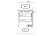
- the mode selection unit 47 selects one from the first mode M1 and the second mode M2 via a menu 63 output from the remote controller 60 of the first air conditioner 30a as shown in FIG.
- the first user U1 is made to select the mode.
- the screen of the menu 63 is output on the display 61 of the remote controller 60.
- the first user U1 operates the display 61 which is a touch panel, and a first mode M1 displayed as “recommended mode” on the screen and a second mode M2 displayed as “favorite mode” on the screen. Select one of these.
- Information indicating the selected mode is transmitted from the remote controller 60.
- the mode selection unit 47 receives information transmitted from the remote controller 60 via the communication device 43 of the first controller 40.
- the mode selection unit 47 specifies the mode selected by the first user U1 from the received information.
- a mobile terminal such as a smartphone or a tablet may be used for mode selection.
- the “mode” here is different from the operation mode such as cooling operation or heating operation.
- an audio menu may be output from the speaker.
- the first user U1 verbally transmits, via the microphone, which mode to select between the first mode M1 and the second mode M2 according to the voice guidance.
- the mode selection part 47 specifies the mode selected by the 1st user U1.
- step S206 the operation control unit 46 of the first controller 40 selects the second mode M2 when the similarity determination unit 24 determines that the attributes of the first user U1 and the attributes of the second user U2 are similar. If so, the operation of the first air conditioner 30 a is controlled based on the operation information 53 acquired by the information acquisition unit 45. Even if it is determined by the similarity determination unit 24 that the attributes of the first user U1 and the attributes of the second user U2 are similar, the operation control unit 46 is the first air conditioner if the first mode M1 is selected. The operation of 30a is controlled regardless of the operation information 53 acquired by the information acquisition unit 45.
- the operation control part 46 will be the 1st air conditioner 30a. Is controlled without using the driving information 53.
- the operation control unit 46 uses the current information of the second air conditioner 30b as the operation information 53 acquired by the information acquisition unit 45. Information indicating the operation mode is read from the memory 42. The operation control unit 46 stops the operation of the first air conditioner 30a when the read operation information 53 indicates that the operation of the second air conditioner 30b is stopped. When the read operation information 53 indicates that the operation mode of the second air conditioner 30b is set to the specific operation mode, the operation control unit 46 operates the operation mode of the first air conditioner 30a. Is set to the same operation mode as the second air conditioner 30b.
- the operation control unit 46 does not read the operation information 53 from the memory 42, and the menu 64 output by the remote controller 60 as shown in FIG.
- the first user U1 is allowed to make settings related to the operation of the first air conditioner 30a, such as temperature setting.
- the operation control unit 46 controls the operation of the first air conditioner 30a according to the setting by the first user U1.
- a mobile terminal such as a smartphone or a tablet may be used for settings related to the operation of the first air conditioner 30a.
- an audio menu may be output from the speaker.
- the 1st user U1 performs the setting regarding the driving
- the operation control part 46 controls the driving
- step S207 the information output unit 48 of the first controller 40 gives information indicating whether the operation control unit 46 controls the operation of the first air conditioner 30a based on the operation information 53 to the first user U1. Output.
- the information output unit 48 outputs a message 65 as shown in FIG.
- the information output unit 48 outputs a message 65 on the display 61 of the remote controller 60 indicating which mode is applied between the first mode M1 and the second mode M2.
- a mobile terminal such as a smartphone or a tablet may be used for outputting information.
- a voice message may be output from the speaker.
- step S203 The processing from step S203 to step S207 is repeatedly executed.
- the functions of the attribute input unit 44, information acquisition unit 45, operation control unit 46, mode selection unit 47, and information output unit 48 of the first controller 40 are realized by software.
- the functions of the attribute input unit 44, the information acquisition unit 45, the operation control unit 46, the mode selection unit 47, and the information output unit 48 may be realized by hardware.
- the functions of the attribute input unit 44, the information acquisition unit 45, the operation control unit 46, the mode selection unit 47, and the information output unit 48 may be realized by a combination of software and hardware.
- Embodiment 3 FIG. In the present embodiment, differences from the first embodiment will be mainly described with reference to FIGS.
- the operation of the first air conditioner 30a is the second. It is controlled with reference to the operation information 53 of the air conditioner 30b. In the present embodiment, information that is most likely to obtain the energy saving effect is selected as the operation information 53 to be referred to.
- control system 10 includes a server 20 and a number of air conditioners 30 that can communicate with the server 20 via the network 11 such as the Internet.
- each air conditioner 30 is either the first air conditioner 30a or the second air conditioner 30b.
- the configuration of the server 20 will be described with reference to FIG.
- the server 20 includes an air conditioner selecting unit 26 in addition to the similarity determining unit 24 and the information providing unit 25 as functional elements.
- the functions of the similarity determining unit 24, the information providing unit 25, and the air conditioner selecting unit 26 are realized by software. Specifically, the functions of the similarity determining unit 24, the information providing unit 25, and the air conditioner selecting unit 26 are realized by a server program.
- the server program is a program that causes the computer to execute the processes performed by the similarity determination unit 24, the information provision unit 25, and the air conditioner selection unit 26 as a similarity determination process, an information provision process, and an air conditioner selection process, respectively.
- the memory 22 stores energy information 54.
- Energy information 54 is information indicating at least one of the energy consumption amount and the energy usage fee of the second air conditioner 30b. Specifically, the energy information 54 is information indicating at least one of the power consumption and the electricity cost of the second air conditioner 30b.
- the energy information 54 may be acquired from an arbitrary information source through an arbitrary route. In the present embodiment, the energy information 54 is acquired from the second air conditioner 30 b via the network 11.
- each air conditioner 30 Since the configuration of each air conditioner 30 is the same as that of the first embodiment shown in FIGS. 3 and 4, description thereof will be omitted.
- the configuration of the first controller 40 provided in the first air conditioner 30a is the same as that of the first embodiment shown in FIG.
- step S301 and step S302 Since the processing in step S301 and step S302 is the same as the processing in step S101 and step S102 in the first embodiment, description thereof will be omitted.
- step S302 it is assumed that the similarity determination unit 24 of the server 20 selects a plurality of users Us, each of which is a user Ux. That is, it is assumed that the attributes of the first user U1 who uses the first air conditioner 30a are similar to the attributes of a plurality of users Us, each of which is the second user U2 who uses the second air conditioner 30b. .
- the air conditioner selection unit 26 of the server 20 refers to the energy information 54 for the plurality of air conditioners 30 each of which is the second air conditioner 30b and is used by the plurality of users Us.
- One or more air conditioners 30 are selected from the plurality of air conditioners 30.
- the energy information 54 is information indicating at least one of the energy consumption amount and the energy usage fee of each air conditioner 30.
- the air conditioner selection unit 26 receives the energy information 54 transmitted from the second air conditioner 30b via the network 11 via the communication device 23 of the server 20. Periodically, the energy information 54 may be transmitted together with the operation information 53 from the second air conditioner 30 b to the server 20, and the energy information 54 together with the operation information 53 may be transmitted to the second air conditioner according to a request from the server 20. It may be transmitted from the machine 30b to the server 20.
- the air conditioner selection unit 26 writes the received energy information 54 in the memory 22 of the server 20. Thereby, as the energy information 54, information indicating at least one of the latest power consumption and the electricity cost of the second air conditioner 30b is stored in the memory 22.
- the air conditioner selection unit 26 reads the energy information 54 from the memory 22 for the plurality of air conditioners 30 used by the plurality of users Us.
- the air conditioner selection unit 26 selects the air conditioner 30 having the minimum value indicated in the read energy information 54 from the plurality of air conditioners 30. That is, the air conditioner selection unit 26 selects the air conditioner 30 that has the least amount of power consumption. Or the air conditioner selection part 26 selects the air conditioner 30 in which the latest electricity bill was the cheapest.
- the air conditioner 30 whose operation is stopped may be excluded from the options. That is, the air conditioner selection unit 26 selects the air conditioner 30 having the minimum value indicated in the energy information 54 from the operating air conditioners 30 used by the plurality of users Us. Also good.
- step S304 the information providing unit 25 of the server 20 provides the first controller 40 with the operation information 53 obtained during operation by the air conditioner 30 selected by the air conditioner selecting unit 26.
- the information providing unit 25 receives the operation information 53 transmitted together with the energy information 54 from the air conditioner 30 selected by the air conditioner selecting unit 26 via the communication device 23.
- the information providing unit 25 writes the received operation information 53 in the memory 22.
- information indicating the current operation mode of the second air conditioner 30b is stored in the memory 22 as the operation information 53 corresponding to the energy information 54.
- the information providing unit 25 reads the operation information 53 from the memory 22.
- the information providing unit 25 transmits the read operation information 53 to the first controller 40 via the communication device 23.
- step S305 and step S306 Since the processing of step S305 and step S306 is the same as the processing of step S104 and step S105 in the first embodiment, description thereof will be omitted.
- the operation information 53 of the air conditioner 30 selected by the air conditioner selection unit 26 is acquired by the information acquisition unit 45 of the first controller 40. Therefore, the operation control unit 46 of the first controller 40 inevitably acquires the operation of the first air conditioner 30a by the information acquisition unit 45 for the air conditioner 30 selected by the air conditioner selection unit 26. Control is performed based on the operation information 53.
- step S304 to step S306 is repeatedly executed.
- the functions of the similarity determination unit 24, the information providing unit 25, and the air conditioner selection unit 26 of the server 20 are realized by software.
- the functions of the similarity determining unit 24, the information providing unit 25, and the air conditioner selecting unit 26 may be realized by hardware.
- the function of the similarity determination part 24, the information provision part 25, and the air conditioner selection part 26 may be implement
- the air conditioner selection unit 26 is provided in the server 20, but as a modification, the air conditioner selection unit may be provided in the first controller 40 of the first air conditioner 30a.
- the information providing unit 25 of the server 20 provides the first controller 40 with the operation information 53 of the plurality of air conditioners 30 each of which is the second air conditioner 30b and used by the plurality of users Us.
- the information acquisition unit 45 of the first controller 40 acquires the operation information 53 of the plurality of air conditioners 30.
- the air conditioner selection unit of the first controller 40 refers to the energy information 54 and selects one or more air conditioners 30 from the plurality of air conditioners 30.
- the operation control unit 46 of the first controller 40 controls the operation of the first air conditioner 30a based on the operation information 53 acquired by the information acquisition unit 45 for the air conditioner 30 selected by the air conditioner selection unit. To do.
- Embodiment 4 FIG. In the present embodiment, differences from the first embodiment will be mainly described with reference to FIGS. 15 to 18.
- the data collected by the second air conditioner 30b to identify the attribute of the second user U2 who uses the second air conditioner 30b is an image mounted on the second air conditioner 30b. It is the picked-up image 52 obtained by the sensor 38b. In the present embodiment, data collected for the same purpose is different from the captured image 52.
- control system 10 includes a server 20 and a large number of air conditioners 30 that can communicate with the server 20 via the network 11 such as the Internet.
- each air conditioner 30 is either the first air conditioner 30a or the second air conditioner 30b.
- the second air conditioner 30b is a model with higher functionality than the first air conditioner 30a.
- the second air conditioner 30b is a model on which the image sensor 38b is mounted.
- the second air conditioner 30b is a device 71 such as a smart speaker, a water heater, or a home appliance. This model is equipped with a function to communicate with.
- the 2nd air conditioner 30b is a model by which the function which communicates with apparatus 73, such as a HEMS server which collects data from other apparatuses 72, such as a water heater or a household appliance, is mounted.
- the 1st air conditioner 30a is a model in which the function to communicate with the apparatus 71 or the apparatus 73 is not mounted.
- a model not equipped with a function to communicate with the device 71 or the device 73 has a function to communicate with a low-priced standard model or a medium-price medium model, the device 71 or the device 73.
- This model is a high-priced deluxe model.
- a device 71 such as a smart speaker, a water heater, or a home appliance is connected to the second air conditioner 30b directly or via a network such as a LAN.
- LAN is an abbreviation for Local Area Network.
- the device 71 is installed in the same building as the second air conditioner 30b and is used by the second user U2.
- Home appliances are other than air conditioners, and are, for example, televisions, rice cookers, or refrigerators.
- a device 72 such as a water heater or home appliance is connected to a device 73 such as a HEMS server directly or via a network such as a LAN. As with the device 71, the device 72 is installed in the same building as the second air conditioner 30b and used by the second user U2.
- the device 73 such as a HEMS server may be installed in the same building as the second air conditioner 30b, or may be installed in a place different from the second air conditioner 30b, such as a remote place.
- the configuration of the server 20 will be described with reference to FIG.
- the memory 22 stores a use history 55 instead of the captured image 52.
- the usage history 55 is a history of the use of the device 71 or the device 72 by the second user U2. If the device 71 is a smart speaker, the usage history 55 is data in which a conversation made by the second user U2 as a smart speaker is recorded for each date and time. If the device 71 or the device 72 is a water heater, the use history 55 is data in which the bath temperature set by the second user U2 and the time when the second user U2 took a bath are recorded for each date and time. If the device 71 or the device 72 is a television, the usage history 55 is data in which the genre of the program viewed on the television by the second user U2 is recorded for each date and time. In the server 20, the usage history 55 may be acquired from an arbitrary information source through an arbitrary route, but is acquired from the second air conditioner 30 b via the network 11 in the present embodiment.
- each air conditioner 30 Since the configuration of each air conditioner 30 is the same as that of the first embodiment shown in FIGS. 3 and 4, description thereof will be omitted.
- the configuration of the first controller 40 provided in the first air conditioner 30a is the same as that of the first embodiment shown in FIG.
- step S401 attribute information 51 indicating the attribute of the first user U1 who uses the first air conditioner 30a is input to the attribute input unit 44 of the first controller 40.
- the attribute information 51 is input to the attribute input unit 44 via a menu 66 output from the remote controller 60 of the first air conditioner 30a as shown in FIG.
- the screen of the menu 66 is output on the display 61 of the remote controller 60.
- the first user U1 operates the display 61, which is a touch panel, and selects an attribute such as an action pattern or a preference from items displayed on the screen.
- Information indicating the selected attribute is transmitted as attribute information 51 from the remote controller 60.
- the attribute input unit 44 receives the attribute information 51 transmitted from the remote controller 60 via the communication device 43 of the first controller 40. That is, the attribute information 51 is input from the remote controller 60 to the attribute input unit 44.
- the attribute input unit 44 writes the input attribute information 51 in the memory 42 of the first controller 40.
- a mobile terminal such as a smartphone or a tablet may be used for inputting the attribute information 51.
- an audio menu may be output from the speaker.
- the 1st user U1 transmits attributes, such as an action pattern or a preference, orally via a microphone according to voice guidance. Then, information indicating the transmitted attribute is input to the attribute input unit 44 as attribute information 51.
- the attribute input unit 44 reads the attribute information 51 from the memory 42.
- the attribute input unit 44 transmits the read attribute information 51 to the server 20 via the communication device 43.
- step S402 the similarity determination unit 24 of the server 20 identifies the attribute of the second user U2 who uses the second air conditioner 30b from the data collected by the second air conditioner 30b.
- data collected by the second air conditioner 30b is obtained by at least the device 71 and the device 72 by the second user U2 obtained by the device 71 or the device 73 connected to the second air conditioner 30b.
- One of the usage histories 55 is.
- the similarity determination unit 24 determines whether the attribute indicated in the attribute information 51 is similar to the specified attribute.
- the similarity determination unit 24 receives the usage history 55 transmitted from the second air conditioner 30b via the network 11 via the communication device 23 of the server 20. Each time the additional data of the usage history 55 is obtained by the device 71 or the device 73, the obtained additional data may be transmitted from the second air conditioner 30b to the server 20, or periodically accumulated until then.
- the used usage history 55 may be transmitted from the second air conditioner 30b to the server 20. Alternatively, the use history 55 accumulated so far may be transmitted from the second air conditioner 30b to the server 20 in response to a request from the server 20.
- the similarity determination unit 24 writes the received usage history 55 in the memory 22 of the server 20. As a result, the use history 55 obtained over a certain period such as the most recent one week, one month, several months, or one year is stored in the memory 22.
- the similarity determination unit 24 receives the attribute information 51 transmitted from the first controller 40 via the network 11 via the communication device 23.
- the similarity determination unit 24 writes the received attribute information 51 into the memory 22.
- the similarity determination unit 24 reads the attribute information 51 and the usage history 55 from the memory 22.
- the similarity determination unit 24 identifies attributes such as the sex, age, and family structure of the first user U1 from the read attribute information 51.
- the similarity determination unit 24 specifies an attribute such as a behavior pattern or a preference of the second user U2 from the read usage history 55.
- a known algorithm may be used, or a dedicated algorithm may be used.
- the similarity determination unit 24 determines whether the attributes of the identified first user U1 and second user U2 are similar.
- any criterion may be used as a criterion for determination, but in this embodiment, the attributes are similar if the clusters corresponding to the behavior pattern or preference match, and the attributes are not similar if the clusters do not match. Is done. Which cluster each user belongs to is determined using an existing clustering technique.
- the similarity determination unit 24 acquires the use history 55 from two or more air conditioners 30 that are each the second air conditioner 30b.
- the similarity determination unit 24 specifies the attributes of two or more users who are each the second user U2 and use two or more air conditioners 30 from the acquired usage history 55.
- the similarity determination unit 24 selects a user Ux whose specified attribute is similar to the attribute of the first user U1 from the two or more users.
- step S403 the information providing unit 25 of the server 20 obtains during operation by the second air conditioner 30b when the attribute indicated in the attribute information 51 is similar to the attribute specified from the usage history 55.
- the obtained operation information 53 is provided to the first controller 40.
- step S404 and step S405 Since the processing in step S404 and step S405 is the same as the processing in step S104 and step S105 in the first embodiment, description thereof will be omitted.
- step S403 to step S405 is repeatedly executed.
- the operation of the first air conditioner 30a is the second. It is controlled based on the operation information 53 of the air conditioner 30b.
- the user's attribute is specified from the data obtained by the connected device 71 or the device 73, so that the trouble of registering the attribute information 51 can be saved.
- a lower function model than the 2nd air conditioner 30b can be applied to the 1st air conditioner 30a. .
- the user attribute is automatically recognized, whereas in the first air conditioner 30a, such a function is omitted, and the user attribute is manually input. Therefore, according to the present embodiment, it is possible to reduce the trouble of registering the attribute information 51 while allowing a mixture of a low function model and a high function model.
- the similarity determination unit 24 of the server 20 uses the second air conditioner 30b from the use history 55 obtained by the device 71 or the device 73 connected to the second air conditioner 30b.
- the 2nd air harmony machine 30b may have a function equivalent to this function instead of server 20. That is, in step S402 of this modification, the second air conditioner 30b uses the second air conditioner 30b from the usage history 55 obtained by the device 71 or the device 73 connected to the second air conditioner 30b.
- the attribute of the second user U2 to be identified is specified.
- the second air conditioner 30b transmits information indicating the specified attribute to the server 20.
- the similarity determination unit 24 of the server 20 receives the information transmitted from the second air conditioner 30b via the network 11, and uses the attribute indicated in the attribute information 51 and the information received from the second air conditioner 30b. Determine if the attribute shown is similar. According to this modification, the amount of data stored in the cloud can be reduced. Moreover, since it is not necessary to disclose the usage history 55 related to the privacy of the second user U2 to the cloud, the privacy can be reliably protected.
Landscapes
- Engineering & Computer Science (AREA)
- Human Computer Interaction (AREA)
- Chemical & Material Sciences (AREA)
- Combustion & Propulsion (AREA)
- Mechanical Engineering (AREA)
- General Engineering & Computer Science (AREA)
- Air Conditioning Control Device (AREA)
- Selective Calling Equipment (AREA)
Abstract
第1空気調和機(30a)を使用するユーザの属性と、第2空気調和機(30b)を使用するユーザの属性とが類似するとサーバ(20)によって判断された場合に、第1空気調和機(30a)の運転が第2空気調和機(30b)の運転情報に基づいて制御される。第2空気調和機(30b)については、第2空気調和機(30b)により収集されたデータからユーザの属性がサーバ(20)によって特定される。第1空気調和機(30a)については、第1空気調和機(30a)に入力された情報からユーザの属性がサーバ(20)によって特定される。
Description
本発明は、制御システム、空気調和機およびサーバに関するものである。
特許文献1に記載の技術では、各エネルギー消費機器が、ユーザの属性が同じエネルギー消費機器の制御値に対して導出された平均値を定期的に受信し、ユーザの選択に基づいて設定された運転モードに合わせて、各エネルギー消費機器の制御値を、受信した平均値に対して一定量変化させる。
特許文献1に記載の技術では、全エネルギー消費機器のユーザの属性情報があらかじめデータベースに登録されていなければならない。
属性情報の登録の手間を省くために、各エネルギー消費機器にイメージセンサを搭載し、画像認識技術を用いて、イメージセンサにより得られた撮影画像から各エネルギー消費機器のユーザの属性を特定することが考えられる。しかし、その場合、全エネルギー消費機器に高感度のイメージセンサを搭載しなければならなくなる。すなわち、全エネルギー消費機器を高機能なモデルに統一しなければならなくなる。
属性情報の登録の手間を省くために、各エネルギー消費機器にスマートスピーカ、給湯器、家電またはHEMSサーバといった機器を接続し、接続した機器により得られた、ユーザによる家電の使用履歴からユーザの属性を特定することも考えられる。しかし、その場合、全エネルギー消費機器に、接続した機器と通信する機能を搭載しなければならなくなる。すなわち、全エネルギー消費機器を高機能なモデルに統一しなければならなくなる。「HEMS」は、Home Energy Management Systemの略語である。
本発明は、低機能なモデルと高機能なモデルとの混在を許容しつつ、属性情報の登録の手間を軽減することを目的とする。
本発明の一態様に係る制御システムは、
第1空気調和機を使用する第1ユーザの属性を示す属性情報が入力される属性入力部と、
前記第1空気調和機とは別の第2空気調和機により運転中に得られた運転情報を取得する情報取得部と、
前記属性入力部に入力された属性情報に示されている属性と、前記第2空気調和機により収集されたデータから特定される、前記第2空気調和機を使用する第2ユーザの属性とが類似する場合に、前記第1空気調和機の運転を、前記情報取得部により取得された運転情報に基づいて制御する運転制御部と
を備える。
第1空気調和機を使用する第1ユーザの属性を示す属性情報が入力される属性入力部と、
前記第1空気調和機とは別の第2空気調和機により運転中に得られた運転情報を取得する情報取得部と、
前記属性入力部に入力された属性情報に示されている属性と、前記第2空気調和機により収集されたデータから特定される、前記第2空気調和機を使用する第2ユーザの属性とが類似する場合に、前記第1空気調和機の運転を、前記情報取得部により取得された運転情報に基づいて制御する運転制御部と
を備える。
本発明では、第1空気調和機を使用するユーザの属性と、第2空気調和機を使用するユーザの属性とが類似する場合に、第1空気調和機の運転が第2空気調和機の運転情報に基づいて制御される。第2空気調和機については、収集されたデータからユーザの属性が特定されるため、属性情報の登録の手間を省くことができる。第1空気調和機については、入力された情報からユーザの属性が特定されるため、第1空気調和機には、第2空気調和機よりも低機能なモデルを適用することができる。よって、本発明によれば、低機能なモデルと高機能なモデルとの混在を許容しつつ、属性情報の登録の手間を軽減することができる。
以下、本発明の実施の形態について、図を用いて説明する。各図中、同一または相当する部分には、同一符号を付している。実施の形態の説明において、同一または相当する部分については、説明を適宜省略または簡略化する。なお、本発明は、以下に説明する実施の形態に限定されるものではなく、必要に応じて種々の変更が可能である。例えば、以下に説明する実施の形態のうち、2つ以上の実施の形態が組み合わせられて実施されても構わない。あるいは、以下に説明する実施の形態のうち、1つの実施の形態または2つ以上の実施の形態の組み合わせが部分的に実施されても構わない。
実施の形態1.
本実施の形態について、図1から図7を用いて説明する。
本実施の形態について、図1から図7を用いて説明する。
***構成の説明***
図1を参照して、本実施の形態に係る制御システム10の構成を説明する。
図1を参照して、本実施の形態に係る制御システム10の構成を説明する。
制御システム10は、サーバ20と、インターネット等のネットワーク11を介してサーバ20と通信可能な多数の空気調和機30とを備える。
各空気調和機30は、第1空気調和機30aと第2空気調和機30bとのいずれかである。第2空気調和機30bは、第1空気調和機30aよりも高機能なモデルである。具体的には、第2空気調和機30bは、イメージセンサ38bが搭載されたモデルであるのに対し、第1空気調和機30aは、イメージセンサ38aが搭載されていないモデルと、第2空気調和機30bに搭載されたイメージセンサ38bよりも低感度のイメージセンサ38aが搭載されたモデルとのいずれかである。空気調和機30のラインアップでは、イメージセンサが搭載されていないモデルが低価格帯のスタンダードモデル、イメージセンサ38aが搭載されたモデルが中価格帯のミディアムモデル、イメージセンサ38bが搭載されたモデルが高価格帯のデラックスモデルである。
第1空気調和機30aに搭載されたイメージセンサ38aは、本実施の形態では赤外線センサであるが、カメラでもよい。第2空気調和機30bに搭載されたイメージセンサ38bは、本実施の形態ではイメージセンサ38aよりも高解像度の赤外線センサであるが、カメラでもよい。
図2を参照して、サーバ20の構成を説明する。
サーバ20は、コンピュータである。サーバ20は、具体的には、クラウドシステムに備えられるサーバコンピュータである。サーバ20は、プロセッサ21を備えるとともに、メモリ22および通信デバイス23といった他のハードウェアを備える。プロセッサ21は、信号線を介して他のハードウェアと接続され、これら他のハードウェアを制御する。
サーバ20は、機能要素として、類似判断部24と、情報提供部25とを備える。類似判断部24および情報提供部25の機能は、ソフトウェアにより実現される。具体的には、類似判断部24および情報提供部25の機能は、サーバプログラムにより実現される。サーバプログラムは、類似判断部24および情報提供部25により行われる処理をそれぞれ類似判断処理および情報提供処理としてコンピュータに実行させるプログラムである。サーバプログラムは、コンピュータ読取可能な媒体に記録されて提供されてもよいし、記録媒体に格納されて提供されてもよいし、プログラムプロダクトとして提供されてもよい。
プロセッサ21は、サーバプログラムを実行する装置である。プロセッサ21は、例えば、CPUである。「CPU」は、Central Processing Unitの略語である。
メモリ22は、サーバプログラムを記憶する装置である。メモリ22は、例えば、RAM、フラッシュメモリまたはこれらの組み合わせである。「RAM」は、Random Access Memoryの略語である。
メモリ22には、属性情報51、撮影画像52および運転情報53が記憶される。
属性情報51は、第1空気調和機30aを使用する第1ユーザU1の属性を示す情報である。属性情報51は、具体的には、第1ユーザU1の性別、年齢および家族構成といった属性を示す情報である。必須ではないが、ライフスタイルも属性として認識されることが望ましい。具体例として、第1ユーザU1が30代男性と30代女性との2人世帯であれば、その世帯が子供を持たない共働き世帯であるかどうかまで認識されることが望ましい。何時に起床し、外出し、帰宅し、入浴し、就寝するかといった行動パターンも属性として認識されてもよい。暑がり、あるいは、寒がりといった好みも属性として認識されてもよい。属性情報51は、本実施の形態では第1ユーザU1により第1空気調和機30aに入力されるが、第1空気調和機30aの据付業者等、第1ユーザU1以外の第三者により第1空気調和機30aに入力されてもよい。サーバ20において、属性情報51は、任意の経路で任意の情報源から取得されてよいが、本実施の形態では、ネットワーク11を介して第1空気調和機30aから直接取得される。
撮影画像52は、第2空気調和機30bに搭載されたイメージセンサ38bにより得られた画像である。撮影画像52は、具体的には、第2空気調和機30bの室内機が設置された住宅等の建物内を撮影して得られた画像である。サーバ20において、撮影画像52は、任意の経路で任意の情報源から取得されてよいが、本実施の形態では、ネットワーク11を介して第2空気調和機30bから直接取得される。
運転情報53は、第2空気調和機30bにより運転中に得られた情報である。運転情報53は、具体的には、第2空気調和機30bの運転モードを示す情報である。運転モードは、例えば、冷房運転、暖房運転、送風運転、空気清浄運転、加湿運転または除湿運転である。運転情報53には、第2空気調和機30bの能力、圧縮機回転速度およびファン回転速度等、第2空気調和機30bの運転に関わる様々なデータが含まれていてもよい。サーバ20において、運転情報53は、任意の経路で任意の情報源から取得されてよいが、本実施の形態では、ネットワーク11を介して第2空気調和機30bから直接取得される。
通信デバイス23は、サーバプログラムに入力されるデータを受信するレシーバと、サーバプログラムから出力されるデータを送信するトランスミッタとを含む。通信デバイス23は、例えば、通信チップまたはNICである。「NIC」は、Network Interface Cardの略語である。
サーバプログラムは、メモリ22からプロセッサ21に読み込まれ、プロセッサ21によって実行される。メモリ22には、サーバプログラムだけでなく、OSも記憶されている。「OS」は、Operating Systemの略語である。プロセッサ21は、OSを実行しながら、サーバプログラムを実行する。なお、サーバプログラムの一部または全部がOSに組み込まれていてもよい。
サーバプログラムおよびOSは、補助記憶装置に記憶されていてもよい。補助記憶装置は、例えば、HDD、フラッシュメモリまたはこれらの組み合わせである。「HDD」は、Hard Disk Driveの略語である。サーバプログラムおよびOSは、補助記憶装置に記憶されている場合、メモリ22にロードされ、プロセッサ21によって実行される。
サーバ20は、プロセッサ21を代替する複数のプロセッサを備えていてもよい。これら複数のプロセッサは、サーバプログラムの実行を分担する。それぞれのプロセッサは、例えば、CPUである。
サーバプログラムにより利用、処理または出力されるデータ、情報、信号値および変数値は、メモリ22、補助記憶装置、または、プロセッサ21内のレジスタまたはキャッシュメモリに記憶される。
サーバ20は、1台のコンピュータで構成されていてもよいし、複数台のコンピュータで構成されていてもよい。サーバ20が複数台のコンピュータで構成されている場合は、類似判断部24および情報提供部25の機能が、各コンピュータに分散されて実現されてもよい。
図3および図4を参照して、各空気調和機30の構成を説明する。
図3は、冷房運転時の冷媒回路31を示している。図4は、暖房運転時の冷媒回路31を示している。
各空気調和機30は、冷媒が循環する冷媒回路31を備える。各空気調和機30は、圧縮機32と、四方弁33と、室外熱交換器である第1熱交換器34と、膨張弁である膨張機構35と、室内熱交換器である第2熱交換器36とをさらに備える。圧縮機32、四方弁33、第1熱交換器34、膨張機構35および第2熱交換器36は、冷媒回路31に接続されている。
圧縮機32は、冷媒を圧縮する。四方弁33は、冷房運転時と暖房運転時とで冷媒の流れる方向を切り替える。第1熱交換器34は、冷房運転時には凝縮器として動作し、圧縮機32により圧縮された冷媒を放熱させる。すなわち、第1熱交換器34は、圧縮機32により圧縮された冷媒を用いて熱交換を行う。第1熱交換器34は、暖房運転時には蒸発器として動作し、室外空気と膨張機構35で膨張した冷媒との間で熱交換を行って冷媒を加熱する。膨張機構35は、凝縮器で放熱した冷媒を膨張させる。第2熱交換器36は、暖房運転時には凝縮器として動作し、圧縮機32により圧縮された冷媒を放熱させる。すなわち、第2熱交換器36は、圧縮機32により圧縮された冷媒を用いて熱交換を行う。第2熱交換器36は、冷房運転時には蒸発器として動作し、室内空気と膨張機構35で膨張した冷媒との間で熱交換を行って冷媒を加熱する。
各空気調和機30は、コントローラ37をさらに備える。
図3および図4では、コントローラ37と圧縮機32との接続しか示していないが、コントローラ37は、圧縮機32だけでなく、冷媒回路31に接続された圧縮機32以外の構成要素に接続されてもよい。コントローラ37は、コントローラ37に接続されている各構成要素の状態を監視したり、制御したりする。
図5を参照して、前述したコントローラ37として第1空気調和機30aに備えられた第1コントローラ40の構成を説明する。
第1コントローラ40は、コンピュータである。第1コントローラ40は、具体的には、マイクロコンピュータである。第1コントローラ40は、プロセッサ41を備えるとともに、メモリ42および通信デバイス43といった他のハードウェアを備える。プロセッサ41は、信号線を介して他のハードウェアと接続され、これら他のハードウェアを制御する。
第1コントローラ40は、機能要素として、属性入力部44と、情報取得部45と、運転制御部46とを備える。属性入力部44、情報取得部45および運転制御部46の機能は、ソフトウェアにより実現される。具体的には、属性入力部44、情報取得部45および運転制御部46の機能は、制御プログラムにより実現される。制御プログラムは、属性入力部44、情報取得部45および運転制御部46により行われる処理をそれぞれ属性入力処理、情報取得処理および運転制御処理としてコンピュータに実行させるプログラムである。制御プログラムは、コンピュータ読取可能な媒体に記録されて提供されてもよいし、記録媒体に格納されて提供されてもよいし、プログラムプロダクトとして提供されてもよい。
プロセッサ41は、制御プログラムを実行する装置である。プロセッサ41は、例えば、CPUである。
メモリ42は、制御プログラムを記憶する装置である。メモリ42は、例えば、RAM、フラッシュメモリまたはこれらの組み合わせである。
メモリ42には、前述した属性情報51および運転情報53が記憶される。
通信デバイス43は、制御プログラムに入力されるデータを受信するレシーバと、制御プログラムから出力されるデータを送信するトランスミッタとを含む。通信デバイス43は、例えば、通信チップまたはNICである。
制御プログラムは、メモリ42からプロセッサ41に読み込まれ、プロセッサ41によって実行される。メモリ42には、制御プログラムだけでなく、OSも記憶されている。プロセッサ41は、OSを実行しながら、制御プログラムを実行する。なお、制御プログラムの一部または全部がOSに組み込まれていてもよい。
第1コントローラ40は、プロセッサ41を代替する複数のプロセッサを備えていてもよい。これら複数のプロセッサは、制御プログラムの実行を分担する。それぞれのプロセッサは、例えば、CPUである。
制御プログラムにより利用、処理または出力されるデータ、情報、信号値および変数値は、メモリ42、または、プロセッサ41内のレジスタまたはキャッシュメモリに記憶される。
第1コントローラ40は、1台のコンピュータで構成されていてもよいし、複数台のコンピュータで構成されていてもよい。第1コントローラ40が複数台のコンピュータで構成されている場合は、属性入力部44、情報取得部45および運転制御部46の機能が、各コンピュータに分散されて実現されてもよい。
***動作の説明***
図6を参照して、本実施の形態に係る制御システム10の動作を説明する。制御システム10の動作は、本実施の形態に係る制御方法に相当する。
図6を参照して、本実施の形態に係る制御システム10の動作を説明する。制御システム10の動作は、本実施の形態に係る制御方法に相当する。
ステップS101において、第1空気調和機30aを使用する第1ユーザU1の属性を示す属性情報51が第1コントローラ40の属性入力部44に入力される。
具体的には、図7に示すような、第1空気調和機30aのリモートコントローラ60で出力されるメニュー62を介して属性情報51が属性入力部44に入力される。
図7の例では、リモートコントローラ60のディスプレイ61でメニュー62の画面が出力される。第1ユーザU1は、タッチパネルであるディスプレイ61を操作して、画面に表示されている項目から性別、年齢および家族構成といった属性を選択する。選択された属性を示す情報が属性情報51としてリモートコントローラ60から送信される。属性入力部44は、第1コントローラ40の通信デバイス43を介して、リモートコントローラ60から送信された属性情報51を受信する。すなわち、リモートコントローラ60から属性情報51が属性入力部44に入力される。属性入力部44は、入力された属性情報51を第1コントローラ40のメモリ42に書き込む。
第1空気調和機30aの専用のリモートコントローラ60に代えて、スマートフォンまたはタブレット等の携帯端末が属性情報51の入力に使用されてもよい。
第1空気調和機30aにスピーカおよびマイクが搭載されている場合は、スピーカから音声メニューが出力されてもよい。その場合、第1ユーザU1は、音声ガイダンスに従って、性別、年齢および家族構成といった属性を、マイクを介して口頭で伝達する。そして、伝達された属性を示す情報が属性情報51として属性入力部44に入力される。
属性入力部44は、属性情報51をメモリ42から読み取る。属性入力部44は、読み取った属性情報51を、通信デバイス43を介してサーバ20に送信する。
ステップS102において、サーバ20の類似判断部24は、第2空気調和機30bにより収集されたデータから、第2空気調和機30bを使用する第2ユーザU2の属性を特定する。第2空気調和機30bにより収集されるデータは、本実施の形態では、第2空気調和機30bに搭載されたイメージセンサ38bにより得られる撮影画像52である。類似判断部24は、属性情報51に示されている属性と、特定した属性とが類似するかどうかを判断する。
具体的には、類似判断部24は、第2空気調和機30bからネットワーク11経由で送信される撮影画像52を、サーバ20の通信デバイス23を介して受信する。イメージセンサ38bにより撮影画像52が得られる度に、その得られた撮影画像52が第2空気調和機30bからサーバ20に送信されてもよいし、定期的に、それまでに蓄積された撮影画像52が第2空気調和機30bからサーバ20に送信されてもよい。あるいは、サーバ20からの要求に応じて、それまでに蓄積された撮影画像52が第2空気調和機30bからサーバ20に送信されてもよい。類似判断部24は、受信した撮影画像52をサーバ20のメモリ22に書き込む。これにより、直近の1週間、1ヵ月、数ヵ月または1年といった一定の期間にわたって得られた撮影画像52がメモリ22に記憶される。
類似判断部24は、第1コントローラ40からネットワーク11経由で送信された属性情報51を、通信デバイス23を介して受信する。類似判断部24は、受信した属性情報51をメモリ22に書き込む。
類似判断部24は、属性情報51および撮影画像52をメモリ22から読み取る。類似判断部24は、読み取った属性情報51から、第1ユーザU1の性別、年齢および家族構成といった属性を特定する。類似判断部24は、読み取った撮影画像52から、第2ユーザU2の性別、年齢および家族構成といった属性を特定する。撮影画像52に写った人間の属性を特定する手法としては、既知の画像認識アルゴリズムを用いてもよいし、専用の画像認識アルゴリズムを用いてもよい。類似判断部24は、特定した第1ユーザU1および第2ユーザU2の属性が類似するかどうかを判断する。判断の基準としては、任意の基準を用いてよいが、本実施の形態では、老人の独り暮らし、あるいは、子供を持たない共働き世帯といったカテゴリが一致すれば属性が類似し、カテゴリが一致しなければ属性が類似しないと判断される。各ユーザがどのカテゴリに属するかは、性別、年齢および家族構成から判断される。
本実施の形態では、類似判断部24は、それぞれが第2空気調和機30bである2つ以上の空気調和機30から撮影画像52を取得する。類似判断部24は、取得した撮影画像52から、それぞれが第2ユーザU2であり2つ以上の空気調和機30を使用する2人以上のユーザの属性を特定する。類似判断部24は、それら2人以上のユーザの中から、特定した属性が第1ユーザU1の属性と類似するユーザUxを選択する。
ユーザUxの選択に際しては、ユーザUxの属性がユーザU1の属性と類似するかどうかだけでなく、ユーザUxの居場所がユーザU1の居場所と近いかどうか、または、ユーザUxの居場所周辺の環境条件がユーザU1の居場所の環境条件と類似するかどうかが考慮されることが望ましい。環境条件は、例えば、気温、湿度もしくは天気等の気象条件、または、大気中に含まれる花粉、PM2.5もしくは黄砂といった粒子の濃度もしくは総量である。
ステップS103において、サーバ20の情報提供部25は、属性情報51に示されている属性と、撮影画像52から特定された属性とが類似する場合に、第2空気調和機30bにより運転中に得られた運転情報53を第1コントローラ40に提供する。
具体的には、情報提供部25は、第2空気調和機30bからネットワーク11経由で送信される運転情報53を、通信デバイス23を介して受信する。定期的に、第2空気調和機30bにより運転情報53が得られ、その得られた運転情報53が第2空気調和機30bからサーバ20に送信されてもよいし、サーバ20からの要求に応じて、第2空気調和機30bにより運転情報53が得られ、その得られた運転情報53が第2空気調和機30bからサーバ20に送信されてもよい。情報提供部25は、受信した運転情報53をメモリ22に書き込む。これにより、運転情報53として、第2空気調和機30bの現在の運転モードを示す情報がメモリ22に記憶される。
情報提供部25は、運転情報53をメモリ22から読み取る。情報提供部25は、読み取った運転情報53を、通信デバイス23を介して第1コントローラ40に送信する。
本実施の形態では、情報提供部25は、類似判断部24により選択されたユーザUxが使用する空気調和機30から運転情報53を取得する。情報提供部25は、取得した運転情報53を第1コントローラ40に送信する。
ステップS104において、第1コントローラ40の情報取得部45は、運転情報53を取得する。
具体的には、情報取得部45は、サーバ20からネットワーク11経由で送信された運転情報53を、通信デバイス43を介して受信する。情報取得部45は、受信した運転情報53をメモリ42に書き込む。
ステップS105において、第1コントローラ40の運転制御部46は、類似判断部24により第1ユーザU1の属性と第2ユーザU2の属性とが類似すると判断された場合に、第1空気調和機30aの運転を、情報取得部45により取得された運転情報53に基づいて制御する。すなわち、運転制御部46は、属性入力部44により特定された属性と、撮影画像52から特定された属性とが類似する場合に、第1空気調和機30aの運転を運転情報53に基づいて制御する。
具体的には、運転制御部46は、情報取得部45により取得された運転情報53として、第2空気調和機30bの現在の運転モードを示す情報をメモリ42から読み取る。運転制御部46は、第2空気調和機30bの運転が停止されていることが、読み取った運転情報53に示されている場合に、第1空気調和機30aの運転を停止する。運転制御部46は、第2空気調和機30bの運転モードが特定の運転モードに設定されていることが、読み取った運転情報53に示されている場合に、第1空気調和機30aの運転モードを第2空気調和機30bと同じ運転モードに設定する。
運転情報53に、第2空気調和機30bの能力、圧縮機回転速度またはファン回転速度等、第2空気調和機30bの運転に関わるデータが含まれている場合は、そのデータと同一または近似の値が第1空気調和機30aの運転に適用されてもよい。すなわち、運転制御部46は、第1空気調和機30aの能力、圧縮機回転速度またはファン回転速度を、第2空気調和機30bと同一または近似の能力、圧縮機回転速度またはファン回転速度に設定してもよい。
本実施の形態では、第1ユーザU1の属性とユーザUxの属性とが類似すると判断された上で、ユーザUxが使用する空気調和機30の運転情報53が情報取得部45により取得される。そのため、運転制御部46は、無条件で、第1空気調和機30aの運転を、情報取得部45により取得された運転情報53に基づいて制御する。
複数の空気調和機30の運転情報53が情報取得部45により取得された場合、運転制御部46は、それら複数の空気調和機30の中から任意の1つの空気調和機30を選択し、選択した空気調和機30の運転情報53を利用してもよいし、それら複数の空気調和機30の運転情報53を統合し、統合した運転情報53を利用してもよい。後者の場合、運転制御部46は、複数の空気調和機30の運転情報53間で共通する部分を第1空気調和機30aの運転に適用する。あるいは、運転制御部46は、複数の空気調和機30の運転情報53から求められる数値の平均値、中央値、最大値または最小値といった代表値を算出し、その代表値を第1空気調和機30aの運転に適用する。
ステップS103からステップS105の処理は、繰り返し実行される。
ステップS101およびステップS102の処理は、第1空気調和機30aの据付時等、第1空気調和機30aの最初の運転よりも前に1度だけ実行されればよい。ステップS103からステップS105の処理により、第1空気調和機30aの運転を完全に自動化できるため、ステップS101でリモートコントローラ60を属性情報51の入力に使用しない場合は、リモートコントローラ60は不要である。リモートコントローラ60をなくすことで、煩わしいリモートコントローラ60の操作からユーザを解放することができる。
なお、ステップS101およびステップS102の処理は、第1空気調和機30aの最初の運転以降であっても、第1ユーザU1の属性が変わった場合等、必要に応じて再実行されてよい。
ステップS103およびステップS104では、第2空気調和機30bにより過去に得られた運転情報53が第1コントローラ40に与えられてもよい。具体的には、運転情報53として、第2空気調和機30bの現在の運転モードを示す情報の代わりに、第2空気調和機30bの数十分前、1時間前または数時間前の運転モードを示す情報、あるいは、第2空気調和機30bの運転モードの変更履歴を示す情報が第1コントローラ40に与えられてもよい。その場合、ステップS105では、第1空気調和機30aの運転が運転情報53に基づいて先回りして制御される。第1空気調和機30aの運転開始時に外気温と室温との差が大きい場合、快適性を高めるには、第1空気調和機30aの高能力運転が必要である。しかし、高能力運転時は省エネルギー性が低下してしまう。そこで、快適性が必要な時間帯よりも前から先回りして低能力運転を開始しておくことで、省エネルギー性を高めることができる。
具体的には、運転制御部46は、第2空気調和機30bの運転モードが特定の運転モードに設定されていたことが運転情報53に示されている場合に、第1空気調和機30aの運転モードをその特定の運転モードに先回りして設定する。運転制御部46は、第2空気調和機30bの運転モードがある運転モードから別の運転モードに変更されたことが運転情報53に示されている場合に、第1空気調和機30aの運転モードを前者の運転モードから後者の運転モードに先回りして変更する。
***実施の形態の効果の説明***
本実施の形態では、第1空気調和機30aを使用するユーザの属性と、第2空気調和機30bを使用するユーザの属性とが類似する場合に、第1空気調和機30aの運転が第2空気調和機30bの運転情報53に基づいて制御される。第2空気調和機30bについては、搭載されたイメージセンサ38bにより得られた画像からユーザの属性が特定されるため、属性情報51の登録の手間を省くことができる。第1空気調和機30aについては、入力された情報からユーザの属性が特定されるため、第1空気調和機30aには、第2空気調和機30bよりも低機能なモデルを適用することができる。すなわち、第2空気調和機30bでは、ユーザの属性が自動で認識されるのに対し、第1空気調和機30aでは、そのような機能が省略され、ユーザの属性が手動で入力される。よって、本実施の形態によれば、低機能なモデルと高機能なモデルとの混在を許容しつつ、属性情報51の登録の手間を軽減することができる。
本実施の形態では、第1空気調和機30aを使用するユーザの属性と、第2空気調和機30bを使用するユーザの属性とが類似する場合に、第1空気調和機30aの運転が第2空気調和機30bの運転情報53に基づいて制御される。第2空気調和機30bについては、搭載されたイメージセンサ38bにより得られた画像からユーザの属性が特定されるため、属性情報51の登録の手間を省くことができる。第1空気調和機30aについては、入力された情報からユーザの属性が特定されるため、第1空気調和機30aには、第2空気調和機30bよりも低機能なモデルを適用することができる。すなわち、第2空気調和機30bでは、ユーザの属性が自動で認識されるのに対し、第1空気調和機30aでは、そのような機能が省略され、ユーザの属性が手動で入力される。よって、本実施の形態によれば、低機能なモデルと高機能なモデルとの混在を許容しつつ、属性情報51の登録の手間を軽減することができる。
***他の構成***
本実施の形態では、サーバ20の類似判断部24および情報提供部25の機能がソフトウェアにより実現されるが、変形例として、類似判断部24および情報提供部25の機能が専用のハードウェアにより実現されてもよい。あるいは、類似判断部24および情報提供部25の機能がソフトウェアと専用のハードウェアとの組み合わせにより実現されてもよい。すなわち、類似判断部24および情報提供部25の機能の一部が専用のハードウェアにより実現され、残りがソフトウェアにより実現されてもよい。
本実施の形態では、サーバ20の類似判断部24および情報提供部25の機能がソフトウェアにより実現されるが、変形例として、類似判断部24および情報提供部25の機能が専用のハードウェアにより実現されてもよい。あるいは、類似判断部24および情報提供部25の機能がソフトウェアと専用のハードウェアとの組み合わせにより実現されてもよい。すなわち、類似判断部24および情報提供部25の機能の一部が専用のハードウェアにより実現され、残りがソフトウェアにより実現されてもよい。
専用のハードウェアは、例えば、単一回路、複合回路、プログラム化したプロセッサ、並列プログラム化したプロセッサ、ロジックIC、GA、FPGA、ASIC、または、これらのうちいくつか、もしくは、すべての組み合わせである。「IC」は、Integrated Circuitの略語である。「GA」は、Gate Arrayの略語である。「FPGA」は、Field-Programmable Gate Arrayの略語である。「ASIC」は、Application Specific Integrated Circuitの略語である。
プロセッサ21および専用のハードウェアは、いずれも処理回路である。すなわち、類似判断部24および情報提供部25の機能がソフトウェアにより実現されるか、ソフトウェアとハードウェアとの組み合わせにより実現されるかに関わらず、類似判断部24および情報提供部25の動作は、処理回路により行われる。
本実施の形態では、第1コントローラ40の属性入力部44、情報取得部45および運転制御部46の機能がソフトウェアにより実現されるが、変形例として、属性入力部44、情報取得部45および運転制御部46の機能が専用のハードウェアにより実現されてもよい。あるいは、属性入力部44、情報取得部45および運転制御部46の機能がソフトウェアと専用のハードウェアとの組み合わせにより実現されてもよい。すなわち、属性入力部44、情報取得部45および運転制御部46の機能の一部が専用のハードウェアにより実現され、残りがソフトウェアにより実現されてもよい。
専用のハードウェアは、例えば、単一回路、複合回路、プログラム化したプロセッサ、並列プログラム化したプロセッサ、ロジックIC、GA、FPGA、ASIC、または、これらのうちいくつか、もしくは、すべての組み合わせである。
プロセッサ41および専用のハードウェアは、いずれも処理回路である。すなわち、属性入力部44、情報取得部45および運転制御部46の機能がソフトウェアにより実現されるか、ハードウェアにより実現されるか、ソフトウェアとハードウェアとの組み合わせにより実現されるかに関わらず、属性入力部44、情報取得部45および運転制御部46の動作は、処理回路により行われる。
本実施の形態では、属性入力部44、情報取得部45および運転制御部46が第1空気調和機30aの第1コントローラ40に備えられるが、変形例として、属性入力部、情報取得部および運転制御部がサーバ20に備えられてもよい。すなわち、サーバ20と第1空気調和機30aとが全体で制御システム10として機能する代わりに、サーバ20が単独で制御システムとして機能し、ネットワーク11を介して第1空気調和機30aの運転を制御してもよい。
本実施の形態では、類似判断部24および情報提供部25がサーバ20に備えられるが、変形例として、類似判断部が第1空気調和機30aの第1コントローラ40に備えられ、情報提供部25が省略されてもよい。すなわち、サーバ20と第1空気調和機30aとが全体で制御システム10として機能する代わりに、第1空気調和機30aが単独で制御システムとして機能してもよい。
本実施の形態では、サーバ20の類似判断部24が、第2空気調和機30bに搭載されたイメージセンサ38bにより得られた撮影画像52から、第2空気調和機30bを使用する第2ユーザU2の属性を特定する機能を有するが、変形例として、この機能と同等の機能を第2空気調和機30bがサーバ20の代わりに有していてもよい。すなわち、この変形例のステップS102では、第2空気調和機30bが、第2空気調和機30bに搭載されたイメージセンサ38bにより得られた撮影画像52から、第2空気調和機30bを使用する第2ユーザU2の属性を特定する。第2空気調和機30bは、特定した属性を示す情報をサーバ20に送信する。サーバ20の類似判断部24は、第2空気調和機30bからネットワーク11経由で送信された情報を受信し、属性情報51に示されている属性と、第2空気調和機30bから受信した情報に示されている属性とが類似するかどうかを判断する。この変形例によれば、クラウドで蓄積するデータの量を削減することができる。また、第2ユーザU2のプライバシーに関わる撮影画像52をクラウドに開示しなくてよいため、プライバシーを確実に保護できる。
本実施の形態では、第1空気調和機30aが第2空気調和機30bよりも低機能なモデルであるが、変形例として、第1空気調和機30aを第2空気調和機30bと同等以上のモデルとしてもよい。
実施の形態2.
本実施の形態について、主に実施の形態1との差異を、図8から図12を用いて説明する。
本実施の形態について、主に実施の形態1との差異を、図8から図12を用いて説明する。
実施の形態1では、第1空気調和機30aを使用するユーザの属性と、第2空気調和機30bを使用するユーザの属性とが類似する場合に、無条件で、第1空気調和機30aの運転が第2空気調和機30bの運転情報53に基づいて制御される。本実施の形態では、「無条件」が「条件付き」に変更される。
***構成の説明***
本実施の形態に係る制御システム10は、実施の形態1と同じように、サーバ20と、インターネット等のネットワーク11を介してサーバ20と通信可能な多数の空気調和機30とを備える。
本実施の形態に係る制御システム10は、実施の形態1と同じように、サーバ20と、インターネット等のネットワーク11を介してサーバ20と通信可能な多数の空気調和機30とを備える。
実施の形態1と同じように、各空気調和機30は、第1空気調和機30aと第2空気調和機30bとのいずれかである。
サーバ20の構成については、図2に示した実施の形態1のものと同じであるため、説明を省略する。
各空気調和機30の構成については、図3および図4に示した実施の形態1のものと同じであるため、説明を省略する。
図8を参照して、第1空気調和機30aに備えられた第1コントローラ40の構成を説明する。
第1コントローラ40は、機能要素として、属性入力部44と、情報取得部45と、運転制御部46とのほかに、モード選択部47と、情報出力部48とを備える。属性入力部44、情報取得部45、運転制御部46、モード選択部47および情報出力部48の機能は、ソフトウェアにより実現される。具体的には、属性入力部44、情報取得部45、運転制御部46、モード選択部47および情報出力部48の機能は、制御プログラムにより実現される。制御プログラムは、属性入力部44、情報取得部45、運転制御部46、モード選択部47および情報出力部48により行われる処理をそれぞれ属性入力処理、情報取得処理、運転制御処理、モード選択処理および情報出力処理としてコンピュータに実行させるプログラムである。
***動作の説明***
図9を参照して、本実施の形態に係る制御システム10の動作を説明する。制御システム10の動作は、本実施の形態に係る制御方法に相当する。
図9を参照して、本実施の形態に係る制御システム10の動作を説明する。制御システム10の動作は、本実施の形態に係る制御方法に相当する。
ステップS201からステップS204の処理については、実施の形態1におけるステップS101からステップS104の処理と同じであるため、説明を省略する。
ステップS205において、第1コントローラ40のモード選択部47は、第1モードM1と第2モードM2とから1つのモードを、第1空気調和機30aを使用する第1ユーザU1に選択させる。第1モードM1は、第1空気調和機30aの運転を、第2空気調和機30bにより運転中に得られた運転情報53によらずに制御するモードである。第2モードM2は、第1空気調和機30aの運転を運転情報53に基づいて制御するモードである。
具体的には、モード選択部47は、図10に示すような、第1空気調和機30aのリモートコントローラ60で出力されるメニュー63を介して第1モードM1と第2モードM2とから1つのモードを第1ユーザU1に選択させる。
図10の例では、リモートコントローラ60のディスプレイ61でメニュー63の画面が出力される。第1ユーザU1は、タッチパネルであるディスプレイ61を操作して、画面に「おすすめモード」として表示されている第1モードM1と、画面に「おこのみモード」として表示されている第2モードM2とのいずれか一方を選択する。選択されたモードを示す情報がリモートコントローラ60から送信される。モード選択部47は、第1コントローラ40の通信デバイス43を介して、リモートコントローラ60から送信された情報を受信する。モード選択部47は、受信した情報から、第1ユーザU1により選択されたモードを特定する。
第1空気調和機30aの専用のリモートコントローラ60に代えて、スマートフォンまたはタブレット等の携帯端末がモードの選択に使用されてもよい。なお、ここでいう「モード」は、冷房運転または暖房運転といった運転モードとは異なる。
第1空気調和機30aにスピーカおよびマイクが搭載されている場合は、スピーカから音声メニューが出力されてもよい。その場合、第1ユーザU1は、音声ガイダンスに従って、第1モードM1と第2モードM2とのうち、どちらのモードを選択するかを、マイクを介して口頭で伝達する。そして、モード選択部47は、第1ユーザU1により選択されたモードを特定する。
ステップS206において、第1コントローラ40の運転制御部46は、類似判断部24により第1ユーザU1の属性と第2ユーザU2の属性とが類似すると判断された場合に、第2モードM2が選択されていれば、第1空気調和機30aの運転を、情報取得部45により取得された運転情報53に基づいて制御する。運転制御部46は、類似判断部24により第1ユーザU1の属性と第2ユーザU2の属性とが類似すると判断された場合でも、第1モードM1が選択されていれば、第1空気調和機30aの運転を、情報取得部45により取得された運転情報53によらずに制御する。すなわち、運転制御部46は、第1ユーザU1の属性と第2ユーザU2の属性とが類似する場合でも、第1ユーザU1により第1モードM1が選択されていれば、第1空気調和機30aの運転を運転情報53によらずに制御する。
具体的には、運転制御部46は、モード選択部47により特定されたモードが第2モードM2であれば、情報取得部45により取得された運転情報53として、第2空気調和機30bの現在の運転モードを示す情報をメモリ42から読み取る。運転制御部46は、第2空気調和機30bの運転が停止されていることが、読み取った運転情報53に示されている場合に、第1空気調和機30aの運転を停止する。運転制御部46は、第2空気調和機30bの運転モードが特定の運転モードに設定されていることが、読み取った運転情報53に示されている場合に、第1空気調和機30aの運転モードを第2空気調和機30bと同じ運転モードに設定する。
運転制御部46は、モード選択部47により特定されたモードが第1モードM1であれば、運転情報53をメモリ42から読み取らず、図11に示すような、リモートコントローラ60で出力されるメニュー64を介して、温度設定等、第1空気調和機30aの運転に関わる設定を第1ユーザU1に行わせる。運転制御部46は、第1空気調和機30aの運転を第1ユーザU1による設定に応じて制御する。
第1空気調和機30aの専用のリモートコントローラ60に代えて、スマートフォンまたはタブレット等の携帯端末が第1空気調和機30aの運転に関わる設定に使用されてもよい。
第1空気調和機30aにスピーカおよびマイクが搭載されている場合は、スピーカから音声メニューが出力されてもよい。その場合、第1ユーザU1は、音声ガイダンスに従って、第1空気調和機30aの運転に関わる設定を、マイクを介して口頭で行う。そして、運転制御部46は、第1空気調和機30aの運転を第1ユーザU1による設定に応じて制御する。
ステップS207において、第1コントローラ40の情報出力部48は、運転制御部46が第1空気調和機30aの運転を運転情報53に基づいて制御しているかどうかを示す情報を第1ユーザU1に対して出力する。
具体的には、情報出力部48は、図12に示すようなメッセージ65をリモートコントローラ60で出力する。
図12の例では、情報出力部48は、リモートコントローラ60のディスプレイ61で、第1モードM1と第2モードM2とのうち、どちらのモードが適用されているかを示すメッセージ65を出力する。
第1空気調和機30aの専用のリモートコントローラ60に代えて、スマートフォンまたはタブレット等の携帯端末が情報の出力に使用されてもよい。
第1空気調和機30aにスピーカが搭載されている場合は、スピーカから音声メッセージが出力されてもよい。
ステップS203からステップS207の処理は、繰り返し実行される。
***実施の形態の効果の説明***
本実施の形態では、第1空気調和機30aを使用するユーザの属性と、第2空気調和機30bを使用するユーザの属性とが類似する場合に、第1空気調和機30aの運転を第2空気調和機30bの運転情報53に基づいて制御するかどうかを、第1空気調和機30aを使用するユーザが自由に選択できる。しかも、第1空気調和機30aの運転が第2空気調和機30bの運転情報53に基づいて制御されているかどうかを、第1空気調和機30aを使用するユーザがいつでも確認できる。
本実施の形態では、第1空気調和機30aを使用するユーザの属性と、第2空気調和機30bを使用するユーザの属性とが類似する場合に、第1空気調和機30aの運転を第2空気調和機30bの運転情報53に基づいて制御するかどうかを、第1空気調和機30aを使用するユーザが自由に選択できる。しかも、第1空気調和機30aの運転が第2空気調和機30bの運転情報53に基づいて制御されているかどうかを、第1空気調和機30aを使用するユーザがいつでも確認できる。
***他の構成***
本実施の形態では、実施の形態1と同じように、第1コントローラ40の属性入力部44、情報取得部45、運転制御部46、モード選択部47および情報出力部48の機能がソフトウェアにより実現されるが、実施の形態1の変形例と同じように、属性入力部44、情報取得部45、運転制御部46、モード選択部47および情報出力部48の機能がハードウェアにより実現されてもよい。あるいは、属性入力部44、情報取得部45、運転制御部46、モード選択部47および情報出力部48の機能がソフトウェアとハードウェアとの組み合わせにより実現されてもよい。
本実施の形態では、実施の形態1と同じように、第1コントローラ40の属性入力部44、情報取得部45、運転制御部46、モード選択部47および情報出力部48の機能がソフトウェアにより実現されるが、実施の形態1の変形例と同じように、属性入力部44、情報取得部45、運転制御部46、モード選択部47および情報出力部48の機能がハードウェアにより実現されてもよい。あるいは、属性入力部44、情報取得部45、運転制御部46、モード選択部47および情報出力部48の機能がソフトウェアとハードウェアとの組み合わせにより実現されてもよい。
実施の形態3.
本実施の形態について、主に実施の形態1との差異を、図13および図14を用いて説明する。
本実施の形態について、主に実施の形態1との差異を、図13および図14を用いて説明する。
実施の形態1では、第1空気調和機30aを使用するユーザの属性と、第2空気調和機30bを使用するユーザの属性とが類似する場合に、第1空気調和機30aの運転が第2空気調和機30bの運転情報53を参考にして制御される。本実施の形態では、参考にする運転情報53として、最も省エネルギー効果が得られそうな情報が選択される。
***構成の説明***
本実施の形態に係る制御システム10は、実施の形態1と同じように、サーバ20と、インターネット等のネットワーク11を介してサーバ20と通信可能な多数の空気調和機30とを備える。
本実施の形態に係る制御システム10は、実施の形態1と同じように、サーバ20と、インターネット等のネットワーク11を介してサーバ20と通信可能な多数の空気調和機30とを備える。
実施の形態1と同じように、各空気調和機30は、第1空気調和機30aと第2空気調和機30bとのいずれかである。
図13を参照して、サーバ20の構成を説明する。
サーバ20は、機能要素として、類似判断部24と、情報提供部25とのほかに、空気調和機選択部26を備える。類似判断部24、情報提供部25および空気調和機選択部26の機能は、ソフトウェアにより実現される。具体的には、類似判断部24、情報提供部25および空気調和機選択部26の機能は、サーバプログラムにより実現される。サーバプログラムは、類似判断部24、情報提供部25および空気調和機選択部26により行われる処理をそれぞれ類似判断処理、情報提供処理および空気調和機選択処理としてコンピュータに実行させるプログラムである。
メモリ22には、属性情報51、撮影画像52および運転情報53のほかに、エネルギー情報54が記憶される。
エネルギー情報54は、第2空気調和機30bのエネルギー消費量およびエネルギー使用料の少なくともいずれかの値を示す情報である。エネルギー情報54は、具体的には、第2空気調和機30bの電力消費量および電気代の少なくともいずれかを示す情報である。サーバ20において、エネルギー情報54は、任意の経路で任意の情報源から取得されてよいが、本実施の形態では、ネットワーク11を介して第2空気調和機30bから取得される。
各空気調和機30の構成については、図3および図4に示した実施の形態1のものと同じであるため、説明を省略する。
第1空気調和機30aに備えられた第1コントローラ40の構成については、図5に示した実施の形態1のものと同じであるため、説明を省略する。
***動作の説明***
図14を参照して、本実施の形態に係る制御システム10の動作を説明する。制御システム10の動作は、本実施の形態に係る制御方法に相当する。
図14を参照して、本実施の形態に係る制御システム10の動作を説明する。制御システム10の動作は、本実施の形態に係る制御方法に相当する。
ステップS301およびステップS302の処理については、実施の形態1におけるステップS101およびステップS102の処理と同じであるため、説明を省略する。
ステップS302において、サーバ20の類似判断部24が、それぞれがユーザUxである複数のユーザUsを選択したとする。すなわち、第1空気調和機30aを使用する第1ユーザU1の属性と、それぞれが第2空気調和機30bを使用する第2ユーザU2である複数のユーザUsの属性とが類似しているとする。
ステップS303において、サーバ20の空気調和機選択部26は、それぞれが第2空気調和機30bであり複数のユーザUsにより使用される複数の空気調和機30について、エネルギー情報54を参照して、それら複数の空気調和機30の中から、1つ以上の空気調和機30を選択する。エネルギー情報54は、各空気調和機30のエネルギー消費量およびエネルギー使用料の少なくともいずれかの値を示す情報である。
具体的には、空気調和機選択部26は、第2空気調和機30bからネットワーク11経由で送信されるエネルギー情報54を、サーバ20の通信デバイス23を介して受信する。定期的に、エネルギー情報54が運転情報53とともに第2空気調和機30bからサーバ20に送信されてもよいし、サーバ20からの要求に応じて、エネルギー情報54が運転情報53とともに第2空気調和機30bからサーバ20に送信されてもよい。空気調和機選択部26は、受信したエネルギー情報54をサーバ20のメモリ22に書き込む。これにより、エネルギー情報54として、第2空気調和機30bの直近の電力消費量および電気代の少なくともいずれかを示す情報がメモリ22に記憶される。
空気調和機選択部26は、複数のユーザUsにより使用される複数の空気調和機30について、エネルギー情報54をメモリ22から読み取る。空気調和機選択部26は、それら複数の空気調和機30の中から、読み取ったエネルギー情報54に示されている値が最小値の空気調和機30を選択する。すなわち、空気調和機選択部26は、直近の電力消費量が最も少なかった空気調和機30を選択する。あるいは、空気調和機選択部26は、直近の電気代が最も安かった空気調和機30を選択する。なお、運転が停止されている空気調和機30は選択肢から除外してもよい。すなわち、空気調和機選択部26は、複数のユーザUsにより使用される運転中の空気調和機30の中から、エネルギー情報54に示されている値が最小値の空気調和機30を選択してもよい。
ステップS304において、サーバ20の情報提供部25は、空気調和機選択部26により選択された空気調和機30により運転中に得られた運転情報53を第1コントローラ40に提供する。
具体的には、情報提供部25は、空気調和機選択部26により選択された空気調和機30からエネルギー情報54とともに送信された運転情報53を、通信デバイス23を介して受信する。情報提供部25は、受信した運転情報53をメモリ22に書き込む。これにより、エネルギー情報54に対応する運転情報53として、第2空気調和機30bの現在の運転モードを示す情報がメモリ22に記憶される。
情報提供部25は、運転情報53をメモリ22から読み取る。情報提供部25は、読み取った運転情報53を、通信デバイス23を介して第1コントローラ40に送信する。
ステップS305およびステップS306の処理については、実施の形態1におけるステップS104およびステップS105の処理と同じであるため、説明を省略する。
本実施の形態では、空気調和機選択部26により選択された空気調和機30の運転情報53が第1コントローラ40の情報取得部45により取得される。そのため、第1コントローラ40の運転制御部46は、必然的に、第1空気調和機30aの運転を、空気調和機選択部26により選択された空気調和機30について情報取得部45により取得された運転情報53に基づいて制御する。
ステップS304からステップS306の処理は、繰り返し実行される。
***実施の形態の効果の説明***
本実施の形態では、最も省エネルギー効果が得られた空気調和機30の実際の運転のしかたを参考にして第1空気調和機30aの運転が制御される。そのため、本実施の形態によれば、省エネルギー性を高めることができる。
本実施の形態では、最も省エネルギー効果が得られた空気調和機30の実際の運転のしかたを参考にして第1空気調和機30aの運転が制御される。そのため、本実施の形態によれば、省エネルギー性を高めることができる。
***他の構成***
本実施の形態では、実施の形態1と同じように、サーバ20の類似判断部24、情報提供部25および空気調和機選択部26の機能がソフトウェアにより実現されるが、実施の形態1の変形例と同じように、類似判断部24、情報提供部25および空気調和機選択部26の機能がハードウェアにより実現されてもよい。あるいは、類似判断部24、情報提供部25および空気調和機選択部26の機能がソフトウェアとハードウェアとの組み合わせにより実現されてもよい。
本実施の形態では、実施の形態1と同じように、サーバ20の類似判断部24、情報提供部25および空気調和機選択部26の機能がソフトウェアにより実現されるが、実施の形態1の変形例と同じように、類似判断部24、情報提供部25および空気調和機選択部26の機能がハードウェアにより実現されてもよい。あるいは、類似判断部24、情報提供部25および空気調和機選択部26の機能がソフトウェアとハードウェアとの組み合わせにより実現されてもよい。
本実施の形態では、空気調和機選択部26がサーバ20に備えられるが、変形例として、空気調和機選択部が第1空気調和機30aの第1コントローラ40に備えられてもよい。その場合、サーバ20の情報提供部25は、それぞれが第2空気調和機30bであり複数のユーザUsにより使用される複数の空気調和機30の運転情報53を第1コントローラ40に提供する。第1コントローラ40の情報取得部45は、それら複数の空気調和機30の運転情報53を取得する。第1コントローラ40の空気調和機選択部は、エネルギー情報54を参照して、それら複数の空気調和機30の中から、1つ以上の空気調和機30を選択する。第1コントローラ40の運転制御部46は、第1空気調和機30aの運転を、空気調和機選択部により選択された空気調和機30について情報取得部45により取得された運転情報53に基づいて制御する。
実施の形態4.
本実施の形態について、主に実施の形態1との差異を、図15から図18を用いて説明する。
本実施の形態について、主に実施の形態1との差異を、図15から図18を用いて説明する。
実施の形態1では、第2空気調和機30bを使用する第2ユーザU2の属性を特定するために第2空気調和機30bにより収集されるデータは、第2空気調和機30bに搭載されたイメージセンサ38bにより得られる撮影画像52である。本実施の形態では、同じ目的のために収集されるデータが、撮影画像52とは別のデータである。
***構成の説明***
図15を参照して、本実施の形態に係る制御システム10の構成を説明する。
図15を参照して、本実施の形態に係る制御システム10の構成を説明する。
本実施の形態に係る制御システム10は、実施の形態1と同じように、サーバ20と、インターネット等のネットワーク11を介してサーバ20と通信可能な多数の空気調和機30とを備える。
実施の形態1と同じように、各空気調和機30は、第1空気調和機30aと第2空気調和機30bとのいずれかである。第2空気調和機30bは、第1空気調和機30aよりも高機能なモデルである。実施の形態1では、第2空気調和機30bは、イメージセンサ38bが搭載されたモデルであるが、本実施の形態では、第2空気調和機30bは、スマートスピーカ、給湯器または家電といった機器71と通信する機能が搭載されたモデルである。あるいは、第2空気調和機30bは、給湯器または家電等の他の機器72からデータを収集するHEMSサーバ等の機器73と通信する機能が搭載されたモデルである。第1空気調和機30aは、機器71または機器73と通信する機能が搭載されていないモデルである。空気調和機30のラインアップでは、機器71または機器73と通信する機能が搭載されていないモデルが低価格帯のスタンダードモデルまたは中価格帯のミディアムモデル、機器71または機器73と通信する機能が搭載されたモデルが高価格帯のデラックスモデルである。
スマートスピーカ、給湯器または家電といった機器71は、直接またはLAN等のネットワークを介して第2空気調和機30bに接続される。「LAN」は、Local Area Networkの略語である。機器71は、第2空気調和機30bと同じ住宅等の建物に設置され、第2ユーザU2によって使用される。家電は、空気調和機以外であり、例えば、テレビ、炊飯器または冷蔵庫である。
給湯器または家電等の機器72は、直接またはLAN等のネットワークを介してHEMSサーバ等の機器73に接続される。機器72は、機器71と同じように、第2空気調和機30bと同じ住宅等の建物に設置され、第2ユーザU2によって使用される。
HEMSサーバ等の機器73は、第2空気調和機30bと同じ建物に設置されてもよいし、遠隔地等、第2空気調和機30bとは異なる場所に設置されてもよい。
図16を参照して、サーバ20の構成を説明する。
メモリ22には、属性情報51および運転情報53のほかに、撮影画像52に代えて使用履歴55が記憶される。
使用履歴55は、第2ユーザU2が機器71または機器72を使用した履歴である。機器71がスマートスピーカであれば、使用履歴55は、日時ごとに、第2ユーザU2がスマートスピーカとした会話を記録したデータである。機器71または機器72が給湯器であれば、使用履歴55は、日時ごとに、第2ユーザU2が設定した風呂の温度と第2ユーザU2が入浴した時間とを記録したデータである。機器71または機器72がテレビであれば、使用履歴55は、日時ごとに、第2ユーザU2がテレビで視聴した番組のジャンルを記録したデータである。サーバ20において、使用履歴55は、任意の経路で任意の情報源から取得されてよいが、本実施の形態では、ネットワーク11を介して第2空気調和機30bから取得される。
各空気調和機30の構成については、図3および図4に示した実施の形態1のものと同じであるため、説明を省略する。
第1空気調和機30aに備えられた第1コントローラ40の構成については、図5に示した実施の形態1のものと同じであるため、説明を省略する。
***動作の説明***
図17を参照して、本実施の形態に係る制御システム10の動作を説明する。制御システム10の動作は、本実施の形態に係る制御方法に相当する。
図17を参照して、本実施の形態に係る制御システム10の動作を説明する。制御システム10の動作は、本実施の形態に係る制御方法に相当する。
ステップS401において、第1空気調和機30aを使用する第1ユーザU1の属性を示す属性情報51が第1コントローラ40の属性入力部44に入力される。
具体的には、図18に示すような、第1空気調和機30aのリモートコントローラ60で出力されるメニュー66を介して属性情報51が属性入力部44に入力される。
図18の例では、リモートコントローラ60のディスプレイ61でメニュー66の画面が出力される。第1ユーザU1は、タッチパネルであるディスプレイ61を操作して、画面に表示されている項目から行動パターンまたは好みといった属性を選択する。選択された属性を示す情報が属性情報51としてリモートコントローラ60から送信される。属性入力部44は、第1コントローラ40の通信デバイス43を介して、リモートコントローラ60から送信された属性情報51を受信する。すなわち、リモートコントローラ60から属性情報51が属性入力部44に入力される。属性入力部44は、入力された属性情報51を第1コントローラ40のメモリ42に書き込む。
第1空気調和機30aの専用のリモートコントローラ60に代えて、スマートフォンまたはタブレット等の携帯端末が属性情報51の入力に使用されてもよい。
第1空気調和機30aにスピーカおよびマイクが搭載されている場合は、スピーカから音声メニューが出力されてもよい。その場合、第1ユーザU1は、音声ガイダンスに従って、行動パターンまたは好みといった属性を、マイクを介して口頭で伝達する。そして、伝達された属性を示す情報が属性情報51として属性入力部44に入力される。
属性入力部44は、属性情報51をメモリ42から読み取る。属性入力部44は、読み取った属性情報51を、通信デバイス43を介してサーバ20に送信する。
ステップS402において、サーバ20の類似判断部24は、第2空気調和機30bにより収集されたデータから、第2空気調和機30bを使用する第2ユーザU2の属性を特定する。第2空気調和機30bにより収集されるデータは、本実施の形態では、第2空気調和機30bに接続された機器71または機器73により得られる、第2ユーザU2による機器71および機器72の少なくともいずれかの使用履歴55である。類似判断部24は、属性情報51に示されている属性と、特定した属性とが類似するかどうかを判断する。
具体的には、類似判断部24は、第2空気調和機30bからネットワーク11経由で送信される使用履歴55を、サーバ20の通信デバイス23を介して受信する。機器71または機器73により使用履歴55の追加データが得られる度に、その得られた追加データが第2空気調和機30bからサーバ20に送信されてもよいし、定期的に、それまでに蓄積された使用履歴55が第2空気調和機30bからサーバ20に送信されてもよい。あるいは、サーバ20からの要求に応じて、それまでに蓄積された使用履歴55が第2空気調和機30bからサーバ20に送信されてもよい。類似判断部24は、受信した使用履歴55をサーバ20のメモリ22に書き込む。これにより、直近の1週間、1ヵ月、数ヵ月または1年といった一定の期間にわたって得られた使用履歴55がメモリ22に記憶される。
類似判断部24は、第1コントローラ40からネットワーク11経由で送信された属性情報51を、通信デバイス23を介して受信する。類似判断部24は、受信した属性情報51をメモリ22に書き込む。
類似判断部24は、属性情報51および使用履歴55をメモリ22から読み取る。類似判断部24は、読み取った属性情報51から、第1ユーザU1の性別、年齢および家族構成といった属性を特定する。類似判断部24は、読み取った使用履歴55から、第2ユーザU2の行動パターンまたは好みといった属性を特定する。使用履歴55から人間の属性を特定する手法としては、既知のアルゴリズムを用いてもよいし、専用のアルゴリズムを用いてもよい。類似判断部24は、特定した第1ユーザU1および第2ユーザU2の属性が類似するかどうかを判断する。判断の基準としては、任意の基準を用いてよいが、本実施の形態では、行動パターンまたは好みに応じたクラスタが一致すれば属性が類似し、クラスタが一致しなければ属性が類似しないと判断される。各ユーザがどのクラスタに属するかは、既存のクラスタリング手法を用いて判断される。
本実施の形態では、類似判断部24は、それぞれが第2空気調和機30bである2つ以上の空気調和機30から使用履歴55を取得する。類似判断部24は、取得した使用履歴55から、それぞれが第2ユーザU2であり2つ以上の空気調和機30を使用する2人以上のユーザの属性を特定する。類似判断部24は、それら2人以上のユーザの中から、特定した属性が第1ユーザU1の属性と類似するユーザUxを選択する。
ステップS403において、サーバ20の情報提供部25は、属性情報51に示されている属性と、使用履歴55から特定された属性とが類似する場合に、第2空気調和機30bにより運転中に得られた運転情報53を第1コントローラ40に提供する。
ステップS404およびステップS405の処理については、実施の形態1におけるステップS104およびステップS105の処理と同じであるため、説明を省略する。
ステップS403からステップS405の処理は、繰り返し実行される。
***実施の形態の効果の説明***
本実施の形態では、第1空気調和機30aを使用するユーザの属性と、第2空気調和機30bを使用するユーザの属性とが類似する場合に、第1空気調和機30aの運転が第2空気調和機30bの運転情報53に基づいて制御される。第2空気調和機30bについては、接続された機器71または機器73により得られたデータからユーザの属性が特定されるため、属性情報51の登録の手間を省くことができる。第1空気調和機30aについては、入力された情報からユーザの属性が特定されるため、第1空気調和機30aには、第2空気調和機30bよりも低機能なモデルを適用することができる。すなわち、第2空気調和機30bでは、ユーザの属性が自動で認識されるのに対し、第1空気調和機30aでは、そのような機能が省略され、ユーザの属性が手動で入力される。よって、本実施の形態によれば、低機能なモデルと高機能なモデルとの混在を許容しつつ、属性情報51の登録の手間を軽減することができる。
本実施の形態では、第1空気調和機30aを使用するユーザの属性と、第2空気調和機30bを使用するユーザの属性とが類似する場合に、第1空気調和機30aの運転が第2空気調和機30bの運転情報53に基づいて制御される。第2空気調和機30bについては、接続された機器71または機器73により得られたデータからユーザの属性が特定されるため、属性情報51の登録の手間を省くことができる。第1空気調和機30aについては、入力された情報からユーザの属性が特定されるため、第1空気調和機30aには、第2空気調和機30bよりも低機能なモデルを適用することができる。すなわち、第2空気調和機30bでは、ユーザの属性が自動で認識されるのに対し、第1空気調和機30aでは、そのような機能が省略され、ユーザの属性が手動で入力される。よって、本実施の形態によれば、低機能なモデルと高機能なモデルとの混在を許容しつつ、属性情報51の登録の手間を軽減することができる。
***他の構成***
本実施の形態では、サーバ20の類似判断部24が、第2空気調和機30bに接続された機器71または機器73により得られた使用履歴55から、第2空気調和機30bを使用する第2ユーザU2の属性を特定する機能を有するが、変形例として、この機能と同等の機能を第2空気調和機30bがサーバ20の代わりに有していてもよい。すなわち、この変形例のステップS402では、第2空気調和機30bが、第2空気調和機30bに接続された機器71または機器73により得られた使用履歴55から、第2空気調和機30bを使用する第2ユーザU2の属性を特定する。第2空気調和機30bは、特定した属性を示す情報をサーバ20に送信する。サーバ20の類似判断部24は、第2空気調和機30bからネットワーク11経由で送信された情報を受信し、属性情報51に示されている属性と、第2空気調和機30bから受信した情報に示されている属性とが類似するかどうかを判断する。この変形例によれば、クラウドで蓄積するデータの量を削減することができる。また、第2ユーザU2のプライバシーに関わる使用履歴55をクラウドに開示しなくてよいため、プライバシーを確実に保護できる。
本実施の形態では、サーバ20の類似判断部24が、第2空気調和機30bに接続された機器71または機器73により得られた使用履歴55から、第2空気調和機30bを使用する第2ユーザU2の属性を特定する機能を有するが、変形例として、この機能と同等の機能を第2空気調和機30bがサーバ20の代わりに有していてもよい。すなわち、この変形例のステップS402では、第2空気調和機30bが、第2空気調和機30bに接続された機器71または機器73により得られた使用履歴55から、第2空気調和機30bを使用する第2ユーザU2の属性を特定する。第2空気調和機30bは、特定した属性を示す情報をサーバ20に送信する。サーバ20の類似判断部24は、第2空気調和機30bからネットワーク11経由で送信された情報を受信し、属性情報51に示されている属性と、第2空気調和機30bから受信した情報に示されている属性とが類似するかどうかを判断する。この変形例によれば、クラウドで蓄積するデータの量を削減することができる。また、第2ユーザU2のプライバシーに関わる使用履歴55をクラウドに開示しなくてよいため、プライバシーを確実に保護できる。
10 制御システム、11 ネットワーク、20 サーバ、21 プロセッサ、22 メモリ、23 通信デバイス、24 類似判断部、25 情報提供部、26 空気調和機選択部、30 空気調和機、30a 第1空気調和機、30b 第2空気調和機、31 冷媒回路、32 圧縮機、33 四方弁、34 第1熱交換器、35 膨張機構、36 第2熱交換器、37 コントローラ、38a イメージセンサ、38b イメージセンサ、40 第1コントローラ、41 プロセッサ、42 メモリ、43 通信デバイス、44 属性入力部、45 情報取得部、46 運転制御部、47 モード選択部、48 情報出力部、51 属性情報、52 撮影画像、53 運転情報、54 エネルギー情報、55 使用履歴、60 リモートコントローラ、61 ディスプレイ、62 メニュー、63 メニュー、64 メニュー、65 メッセージ、66 メニュー、71 機器、72 機器、73 機器。
Claims (14)
- 第1空気調和機を使用する第1ユーザの属性を示す属性情報が入力される属性入力部と、
前記第1空気調和機とは別の第2空気調和機により運転中に得られた運転情報を取得する情報取得部と、
前記属性入力部に入力された属性情報に示されている属性と、前記第2空気調和機により収集されたデータから特定される、前記第2空気調和機を使用する第2ユーザの属性とが類似する場合に、前記第1空気調和機の運転を、前記情報取得部により取得された運転情報に基づいて制御する運転制御部と
を備える制御システム。 - 前記第2空気調和機は、前記第1空気調和機よりも高機能なモデルである請求項1に記載の制御システム。
- 前記データは、前記第2空気調和機に搭載されたイメージセンサにより得られた撮影画像である請求項1または2に記載の制御システム。
- 前記第1空気調和機は、イメージセンサが搭載されていないモデルと、前記第2空気調和機に搭載されたイメージセンサよりも低感度のイメージセンサが搭載されたモデルとのいずれかである請求項3に記載の制御システム。
- 前記データは、前記第2空気調和機に接続された機器により得られた、前記第2ユーザによる当該機器および他の機器の少なくともいずれかの使用履歴である請求項1に記載の制御システム。
- 前記使用履歴は、前記第2ユーザが前記第2空気調和機と同じ建物に設置されている機器を使用した履歴である請求項5に記載の制御システム。
- 前記属性情報に示されている属性と、前記データから特定される属性とが類似するかどうかを判断する類似判断部をさらに備え、
前記運転制御部は、前記類似判断部により前記第1ユーザの属性と前記第2ユーザの属性とが類似すると判断された場合に、前記第1空気調和機の運転を前記運転情報に基づいて制御する請求項1から6のいずれか1項に記載の制御システム。 - 前記属性入力部には、前記第1空気調和機のリモートコントローラで出力されるメニューを介して前記属性情報が入力される請求項1から4のいずれか1項に記載の制御システム。
- 前記第1空気調和機の運転を前記運転情報によらずに制御する第1モードと、前記第1空気調和機の運転を前記運転情報に基づいて制御する第2モードとから1つのモードを前記第1ユーザに選択させるモード選択部をさらに備え、
前記運転制御部は、前記第1ユーザの属性と前記第2ユーザの属性とが類似する場合でも、前記第1ユーザにより前記第1モードが選択されていれば、前記第1空気調和機の運転を前記運転情報によらずに制御する請求項1から8のいずれか1項に記載の制御システム。 - 前記運転制御部が前記第1空気調和機の運転を前記運転情報に基づいて制御しているかどうかを示す情報を前記第1ユーザに対して出力する情報出力部をさらに備える請求項1から9のいずれか1項に記載の制御システム。
- 前記第1ユーザの属性と、それぞれが前記第2ユーザである複数のユーザの属性とが類似する場合に、それぞれが前記第2空気調和機であり前記複数のユーザにより使用される複数の空気調和機について、各空気調和機のエネルギー消費量およびエネルギー使用料の少なくともいずれかの値を示すエネルギー情報を参照して、前記複数の空気調和機の中から、1つ以上の空気調和機を選択する空気調和機選択部をさらに備え、
前記運転制御部は、前記第1空気調和機の運転を、前記空気調和機選択部により選択された空気調和機について前記情報取得部により取得された運転情報に基づいて制御する請求項1から10のいずれか1項に記載の制御システム。 - 前記空気調和機選択部は、前記複数の空気調和機の中から、前記エネルギー情報に示されている値が最小値の空気調和機を選択する請求項11に記載の制御システム。
- 前記第1空気調和機であり、請求項1から12のいずれか1項に記載の制御システムを備える空気調和機。
- 請求項1から12のいずれか1項に記載の制御システムであり、ネットワークを介して前記第2空気調和機の運転を制御するサーバ。
Priority Applications (2)
| Application Number | Priority Date | Filing Date | Title |
|---|---|---|---|
| PCT/JP2018/022287 WO2019239473A1 (ja) | 2018-06-11 | 2018-06-11 | 制御システム、空気調和機およびサーバ |
| JP2020524973A JP6910552B2 (ja) | 2018-06-11 | 2018-06-11 | 制御システム、空気調和機およびサーバ |
Applications Claiming Priority (1)
| Application Number | Priority Date | Filing Date | Title |
|---|---|---|---|
| PCT/JP2018/022287 WO2019239473A1 (ja) | 2018-06-11 | 2018-06-11 | 制御システム、空気調和機およびサーバ |
Publications (1)
| Publication Number | Publication Date |
|---|---|
| WO2019239473A1 true WO2019239473A1 (ja) | 2019-12-19 |
Family
ID=68842744
Family Applications (1)
| Application Number | Title | Priority Date | Filing Date |
|---|---|---|---|
| PCT/JP2018/022287 Ceased WO2019239473A1 (ja) | 2018-06-11 | 2018-06-11 | 制御システム、空気調和機およびサーバ |
Country Status (2)
| Country | Link |
|---|---|
| JP (1) | JP6910552B2 (ja) |
| WO (1) | WO2019239473A1 (ja) |
Cited By (1)
| Publication number | Priority date | Publication date | Assignee | Title |
|---|---|---|---|---|
| CN118499898A (zh) * | 2024-05-11 | 2024-08-16 | 广州河东科技有限公司 | 一种与智能家居系统联动的空调器控制方法 |
Citations (4)
| Publication number | Priority date | Publication date | Assignee | Title |
|---|---|---|---|---|
| JP2009228910A (ja) * | 2008-03-19 | 2009-10-08 | Brother Ind Ltd | 空調制御システム |
| JP2011153759A (ja) * | 2010-01-27 | 2011-08-11 | Omron Corp | 制御装置、制御装置連携システム、制御方法、および制御プログラム |
| JP2015038402A (ja) * | 2013-08-19 | 2015-02-26 | 三菱電機株式会社 | 空気調和装置 |
| JP2015124943A (ja) * | 2013-12-26 | 2015-07-06 | 三菱電機株式会社 | 空気調和機の室内機 |
-
2018
- 2018-06-11 WO PCT/JP2018/022287 patent/WO2019239473A1/ja not_active Ceased
- 2018-06-11 JP JP2020524973A patent/JP6910552B2/ja active Active
Patent Citations (4)
| Publication number | Priority date | Publication date | Assignee | Title |
|---|---|---|---|---|
| JP2009228910A (ja) * | 2008-03-19 | 2009-10-08 | Brother Ind Ltd | 空調制御システム |
| JP2011153759A (ja) * | 2010-01-27 | 2011-08-11 | Omron Corp | 制御装置、制御装置連携システム、制御方法、および制御プログラム |
| JP2015038402A (ja) * | 2013-08-19 | 2015-02-26 | 三菱電機株式会社 | 空気調和装置 |
| JP2015124943A (ja) * | 2013-12-26 | 2015-07-06 | 三菱電機株式会社 | 空気調和機の室内機 |
Cited By (1)
| Publication number | Priority date | Publication date | Assignee | Title |
|---|---|---|---|---|
| CN118499898A (zh) * | 2024-05-11 | 2024-08-16 | 广州河东科技有限公司 | 一种与智能家居系统联动的空调器控制方法 |
Also Published As
| Publication number | Publication date |
|---|---|
| JPWO2019239473A1 (ja) | 2020-12-17 |
| JP6910552B2 (ja) | 2021-07-28 |
Similar Documents
| Publication | Publication Date | Title |
|---|---|---|
| US10584892B2 (en) | Air-conditioning control method, air-conditioning control apparatus, and storage medium | |
| JP6735492B2 (ja) | 空気調和機のレコメンド処理を実行するサーバおよびレコメンド処理システム | |
| JP5787858B2 (ja) | 空調制御システム、空調制御方法及びプログラム | |
| US20180267701A1 (en) | Thermostat with customizable user interfaces | |
| US20150168003A1 (en) | Systems and methods for signature-based thermostat control | |
| CN104964395B (zh) | 空调器的控制方法、装置和设备 | |
| GB2561495A (en) | Control device and control program | |
| JP6711635B2 (ja) | ネットワークシステム、電気機器、通信端末、および通信端末のためのプログラム | |
| JP2016206851A (ja) | 制御装置、制御装置の制御方法、制御システム、環境制御機器、および制御プログラム | |
| CN112880148B (zh) | 用于空调的控制方法、装置、电子设备及存储介质 | |
| JP2018021709A (ja) | 空気調和システム | |
| JP2022056416A (ja) | 制御装置、空調システム、空調機制御方法及びプログラム | |
| JP6910552B2 (ja) | 制御システム、空気調和機およびサーバ | |
| US9063555B2 (en) | Heating, ventilation and air conditioning system user interface having seasonal programs and method of operation thereof | |
| CN108518810A (zh) | 用于控制空调器的方法和装置、计算机可读存储介质 | |
| CN119472320A (zh) | 设备控制方法、装置、电子设备及可读存储介质 | |
| CN116088324A (zh) | 一种智慧家居的实现方法、装置、存储介质和电子设备 | |
| CN115451551A (zh) | 一种空调控制方法、装置、可读存储介质及空调 | |
| US11566804B2 (en) | Control system, air conditioner, and control method based on lifestyle log | |
| JP6861889B2 (ja) | 制御システム、空気調和機およびサーバ | |
| US20200336324A1 (en) | Network system | |
| CN113218052A (zh) | 温度调节方法、装置、计算机设备和存储介质 | |
| WO2017199298A1 (ja) | 空気調和システム | |
| Zaharieva et al. | IoT-Based Device for Indoor Premises Relative Humidity Control | |
| JP6635857B2 (ja) | 機器制御システム、機器制御方法、コントローラ、及び機器制御プログラム |
Legal Events
| Date | Code | Title | Description |
|---|---|---|---|
| 121 | Ep: the epo has been informed by wipo that ep was designated in this application |
Ref document number: 18922295 Country of ref document: EP Kind code of ref document: A1 |
|
| ENP | Entry into the national phase |
Ref document number: 2020524973 Country of ref document: JP Kind code of ref document: A |
|
| NENP | Non-entry into the national phase |
Ref country code: DE |
|
| 122 | Ep: pct application non-entry in european phase |
Ref document number: 18922295 Country of ref document: EP Kind code of ref document: A1 |