WO2019230681A1 - 機器ユニット - Google Patents
機器ユニット Download PDFInfo
- Publication number
- WO2019230681A1 WO2019230681A1 PCT/JP2019/020995 JP2019020995W WO2019230681A1 WO 2019230681 A1 WO2019230681 A1 WO 2019230681A1 JP 2019020995 W JP2019020995 W JP 2019020995W WO 2019230681 A1 WO2019230681 A1 WO 2019230681A1
- Authority
- WO
- WIPO (PCT)
- Prior art keywords
- characteristic data
- recording medium
- casing
- flow rate
- command current
- Prior art date
- Legal status (The legal status is an assumption and is not a legal conclusion. Google has not performed a legal analysis and makes no representation as to the accuracy of the status listed.)
- Ceased
Links
Images

Classifications
-
- G—PHYSICS
- G05—CONTROLLING; REGULATING
- G05B—CONTROL OR REGULATING SYSTEMS IN GENERAL; FUNCTIONAL ELEMENTS OF SUCH SYSTEMS; MONITORING OR TESTING ARRANGEMENTS FOR SUCH SYSTEMS OR ELEMENTS
- G05B15/00—Systems controlled by a computer
- G05B15/02—Systems controlled by a computer electric
-
- F—MECHANICAL ENGINEERING; LIGHTING; HEATING; WEAPONS; BLASTING
- F04—POSITIVE - DISPLACEMENT MACHINES FOR LIQUIDS; PUMPS FOR LIQUIDS OR ELASTIC FLUIDS
- F04B—POSITIVE-DISPLACEMENT MACHINES FOR LIQUIDS; PUMPS
- F04B23/00—Pumping installations or systems
- F04B23/04—Combinations of two or more pumps
-
- F—MECHANICAL ENGINEERING; LIGHTING; HEATING; WEAPONS; BLASTING
- F04—POSITIVE - DISPLACEMENT MACHINES FOR LIQUIDS; PUMPS FOR LIQUIDS OR ELASTIC FLUIDS
- F04B—POSITIVE-DISPLACEMENT MACHINES FOR LIQUIDS; PUMPS
- F04B49/00—Control, e.g. of pump delivery, or pump pressure of, or safety measures for, machines, pumps, or pumping installations, not otherwise provided for, or of interest apart from, groups F04B1/00 - F04B47/00
- F04B49/06—Control using electricity
- F04B49/065—Control using electricity and making use of computers
-
- F—MECHANICAL ENGINEERING; LIGHTING; HEATING; WEAPONS; BLASTING
- F04—POSITIVE - DISPLACEMENT MACHINES FOR LIQUIDS; PUMPS FOR LIQUIDS OR ELASTIC FLUIDS
- F04B—POSITIVE-DISPLACEMENT MACHINES FOR LIQUIDS; PUMPS
- F04B49/00—Control, e.g. of pump delivery, or pump pressure of, or safety measures for, machines, pumps, or pumping installations, not otherwise provided for, or of interest apart from, groups F04B1/00 - F04B47/00
- F04B49/22—Control, e.g. of pump delivery, or pump pressure of, or safety measures for, machines, pumps, or pumping installations, not otherwise provided for, or of interest apart from, groups F04B1/00 - F04B47/00 by means of valves
-
- F—MECHANICAL ENGINEERING; LIGHTING; HEATING; WEAPONS; BLASTING
- F04—POSITIVE - DISPLACEMENT MACHINES FOR LIQUIDS; PUMPS FOR LIQUIDS OR ELASTIC FLUIDS
- F04B—POSITIVE-DISPLACEMENT MACHINES FOR LIQUIDS; PUMPS
- F04B53/00—Component parts, details or accessories not provided for in, or of interest apart from, groups F04B1/00 - F04B23/00 or F04B39/00 - F04B47/00
- F04B53/10—Valves; Arrangement of valves
-
- F—MECHANICAL ENGINEERING; LIGHTING; HEATING; WEAPONS; BLASTING
- F16—ENGINEERING ELEMENTS AND UNITS; GENERAL MEASURES FOR PRODUCING AND MAINTAINING EFFECTIVE FUNCTIONING OF MACHINES OR INSTALLATIONS; THERMAL INSULATION IN GENERAL
- F16K—VALVES; TAPS; COCKS; ACTUATING-FLOATS; DEVICES FOR VENTING OR AERATING
- F16K27/00—Construction of housing; Use of materials therefor
- F16K27/04—Construction of housing; Use of materials therefor of sliding valves
-
- F—MECHANICAL ENGINEERING; LIGHTING; HEATING; WEAPONS; BLASTING
- F16—ENGINEERING ELEMENTS AND UNITS; GENERAL MEASURES FOR PRODUCING AND MAINTAINING EFFECTIVE FUNCTIONING OF MACHINES OR INSTALLATIONS; THERMAL INSULATION IN GENERAL
- F16K—VALVES; TAPS; COCKS; ACTUATING-FLOATS; DEVICES FOR VENTING OR AERATING
- F16K37/00—Special means in or on valves or other cut-off apparatus for indicating or recording operation thereof, or for enabling an alarm to be given
-
- G—PHYSICS
- G06—COMPUTING OR CALCULATING; COUNTING
- G06K—GRAPHICAL DATA READING; PRESENTATION OF DATA; RECORD CARRIERS; HANDLING RECORD CARRIERS
- G06K19/00—Record carriers for use with machines and with at least a part designed to carry digital markings
- G06K19/06—Record carriers for use with machines and with at least a part designed to carry digital markings characterised by the kind of the digital marking, e.g. shape, nature, code
- G06K19/06009—Record carriers for use with machines and with at least a part designed to carry digital markings characterised by the kind of the digital marking, e.g. shape, nature, code with optically detectable marking
- G06K19/06018—Record carriers for use with machines and with at least a part designed to carry digital markings characterised by the kind of the digital marking, e.g. shape, nature, code with optically detectable marking one-dimensional coding
- G06K19/06028—Record carriers for use with machines and with at least a part designed to carry digital markings characterised by the kind of the digital marking, e.g. shape, nature, code with optically detectable marking one-dimensional coding using bar codes
-
- G—PHYSICS
- G06—COMPUTING OR CALCULATING; COUNTING
- G06K—GRAPHICAL DATA READING; PRESENTATION OF DATA; RECORD CARRIERS; HANDLING RECORD CARRIERS
- G06K19/00—Record carriers for use with machines and with at least a part designed to carry digital markings
- G06K19/06—Record carriers for use with machines and with at least a part designed to carry digital markings characterised by the kind of the digital marking, e.g. shape, nature, code
- G06K19/06009—Record carriers for use with machines and with at least a part designed to carry digital markings characterised by the kind of the digital marking, e.g. shape, nature, code with optically detectable marking
- G06K19/06037—Record carriers for use with machines and with at least a part designed to carry digital markings characterised by the kind of the digital marking, e.g. shape, nature, code with optically detectable marking multi-dimensional coding
-
- G—PHYSICS
- G06—COMPUTING OR CALCULATING; COUNTING
- G06K—GRAPHICAL DATA READING; PRESENTATION OF DATA; RECORD CARRIERS; HANDLING RECORD CARRIERS
- G06K7/00—Methods or arrangements for sensing record carriers, e.g. for reading patterns
- G06K7/10—Methods or arrangements for sensing record carriers, e.g. for reading patterns by electromagnetic radiation, e.g. optical sensing; by corpuscular radiation
- G06K7/14—Methods or arrangements for sensing record carriers, e.g. for reading patterns by electromagnetic radiation, e.g. optical sensing; by corpuscular radiation using light without selection of wavelength, e.g. sensing reflected white light
- G06K7/1404—Methods for optical code recognition
- G06K7/1408—Methods for optical code recognition the method being specifically adapted for the type of code
- G06K7/1413—1D bar codes
-
- G—PHYSICS
- G06—COMPUTING OR CALCULATING; COUNTING
- G06K—GRAPHICAL DATA READING; PRESENTATION OF DATA; RECORD CARRIERS; HANDLING RECORD CARRIERS
- G06K7/00—Methods or arrangements for sensing record carriers, e.g. for reading patterns
- G06K7/10—Methods or arrangements for sensing record carriers, e.g. for reading patterns by electromagnetic radiation, e.g. optical sensing; by corpuscular radiation
- G06K7/14—Methods or arrangements for sensing record carriers, e.g. for reading patterns by electromagnetic radiation, e.g. optical sensing; by corpuscular radiation using light without selection of wavelength, e.g. sensing reflected white light
- G06K7/1404—Methods for optical code recognition
- G06K7/1408—Methods for optical code recognition the method being specifically adapted for the type of code
- G06K7/1417—2D bar codes
-
- F—MECHANICAL ENGINEERING; LIGHTING; HEATING; WEAPONS; BLASTING
- F04—POSITIVE - DISPLACEMENT MACHINES FOR LIQUIDS; PUMPS FOR LIQUIDS OR ELASTIC FLUIDS
- F04B—POSITIVE-DISPLACEMENT MACHINES FOR LIQUIDS; PUMPS
- F04B2205/00—Fluid parameters
- F04B2205/05—Pressure after the pump outlet
-
- F—MECHANICAL ENGINEERING; LIGHTING; HEATING; WEAPONS; BLASTING
- F04—POSITIVE - DISPLACEMENT MACHINES FOR LIQUIDS; PUMPS FOR LIQUIDS OR ELASTIC FLUIDS
- F04B—POSITIVE-DISPLACEMENT MACHINES FOR LIQUIDS; PUMPS
- F04B2205/00—Fluid parameters
- F04B2205/09—Flow through the pump
Definitions
- the present invention relates to a device unit including two or more devices connected to each other.
- FIG. 3 of Patent Document 1 discloses a device (valve device) in which three proportional solenoid valves are incorporated in one casing.
- a recording medium on which characteristic data (relationship between command current and output pressure) of three proportional solenoid valves is recorded by a barcode is attached to the side surface of the casing.
- the characteristic data recorded on the recording medium is read by a reading device (for example, a barcode reader), and a command current is supplied to those proportional solenoid valves.
- a reading device for example, a barcode reader
- a command current is supplied to those proportional solenoid valves.
- an object of the present invention is to provide a device unit that can efficiently read characteristic data of two or more devices.
- the device unit of the present invention includes two or more devices each including an independent casing connected to each other, and one of the casings of one of the two or more devices.
- One aspect is characterized in that two or more recording media each recording the characteristic data of the two or more devices or the storage destination IP addresses of the characteristic data are attached adjacent to each other.
- a storage destination IP address of device characteristic data corresponding to each recording medium is directly recorded.
- the characteristic data of two or more devices can be read via the Internet. Moreover, since these recording media are attached adjacent to one side of the casing of one device, the characteristic data of two or more devices can be efficiently read in a short time.
- each of the two or more devices is a pump whose discharge flow rate changes according to a command current, and the characteristic data of the device is a relationship between the command current and a discharge flow rate at a specific discharge pressure. There may be.
- the specific discharge pressure may be two different discharge pressures. According to this configuration, calibration according to the discharge pressure of the pump can also be performed.
- each of the two or more devices is a multi-control valve that includes a plurality of spools that change a passage flow rate according to a command current, and the characteristic data of the devices includes the command data in each of the plurality of spools. It may be a relationship between current and the passing flow rate.
- the date when the characteristic data of the corresponding device is measured may be recorded so as to be visible.
- the characteristic data is also remeasured. Since the remeasured date is recorded in the corresponding recording medium so as to be visible, the user can grasp the repair history of the device by looking at the recording medium. Therefore, maintainability on site is improved.
- the two or more recording media may be integrated. According to this configuration, a single object can be used as two or more recording media.
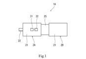
- FIG. 1 shows a device unit 1A according to the first embodiment of the present invention.
- the device unit 1A includes a first device 2A and a second device 2B that are connected to each other.
- the device unit 1A may include three or more devices connected to each other.
- each of the first device 2A and the second device 2B is a variable displacement swash plate pump in which the discharge flow rate changes according to the command current.
- each of the first device 2A and the second device 2B may be an oblique axis pump.
- each of the first device 2A and the second device 2B includes a casing 21 that is independent of each other.
- Each casing 21 is a hexahedron having, for example, six side surfaces.
- One side surface of the casing 21 of the first device 2A and one side surface of the casing 21 of the second device 2B are opposed to each other with the intermediate casing 25 interposed therebetween.
- a cylinder fixed to the rotating shaft 22 a plurality of pistons held by the cylinder, and a chute attached to the tip of each piston slide.
- a swash plate is arranged.
- a cylinder fixed to a rotating shaft (not shown), a plurality of pistons held by the cylinder, a chute and a slide attached to the tip of each piston.
- a moving swash plate is arranged.
- the rotation shaft of the second device 2B is connected to the rotation shaft 22 of the first device 2A within the intermediate casing 25.
- Each of the casing 21 of the first device 2A and the casing 21 of the second device 2B is incorporated with a servo mechanism that changes the angle of the swash plate with respect to a plane orthogonal to the center line of the rotation axis in accordance with the command current.
- the servo mechanism may be configured to electrically change the hydraulic pressure acting on the servo piston connected to the swash plate, or may include an electric actuator connected to the swash plate.
- a first recording medium 31 and a second recording medium 32 are attached adjacent to each other on one side surface of the casing 21 of the first device 2A.
- the first recording medium 31 and the second recording medium 32 may be attached adjacent to one side surface of the casing 21 of the second device 2B.
- the characteristic data of the first device 2A is recorded on the first recording medium 31 with a barcode
- the characteristic data of the second device 2B is recorded on the second recording medium 32 with a barcode
- the barcode is a matrix type two-dimensional code (QR code (registered trademark)).
- the first recording medium 31 and the second recording medium 32 are separate bodies. However, the first recording medium 31 and the second recording medium 32 may be integrated. In this case, a single object can be used as the two recording media 31 and 32.
- the attachment of the first recording medium 31 and the second recording medium 32 to the casing 21 may be, for example, affixed with an adhesive or a double-sided tape, or may be screwed.
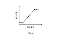
- Each of the characteristic data of the first device 2A and the characteristic data of the second device 2B described above is a relationship between the command current and the discharge flow rate at a specific discharge pressure, as shown in FIG.
- the characteristic data is discrete data as indicated by a plurality of points in FIG. 2, and is measured at a factory before shipment of the corresponding device (2A or 2B). In addition, when the device is repaired (for example, part replacement), the characteristic data is also remeasured.
- each of the first recording medium 31 and the second recording medium 32 the date when the characteristic data of the corresponding device (2A or 2B) is measured is recorded so as to be visible. Further, identification data (individual product number) of the corresponding device (2A or 2B) is also recorded on each of the first recording medium 31 and the second recording medium 32.
- the characteristic data of the first device 2A recorded on the first recording medium 31 includes the relationship between the command current and the discharge flow rate at a relatively low first discharge pressure (for example, 8 MPa), and the relatively high first data.
- the relationship between the command current and the discharge flow rate at two discharge pressures is included.
- the characteristic data of the second device 2B recorded on the second recording medium 32 has a relatively high relationship between the command current and the discharge flow rate at a relatively low first discharge pressure (for example, 8 MPa).
- the relationship between the command current and the discharge flow rate at the second discharge pressure (for example, 15 MPa) is included.
- the characteristic data recorded on each of the first recording medium 31 and the second recording medium 32 may be only the relationship between the command current and the discharge flow rate at one discharge pressure.
- the equipment unit 1A is mounted on, for example, a construction machine (such as a hydraulic excavator or a hydraulic crane) or an industrial machine. And the 1st apparatus 2A and the 2nd apparatus 2B are controlled by the control apparatus of those machines. For example, the control device sends a command current to the first device 2A and the second device 2B in accordance with the operation amount of the operation device operated by the user.
- a construction machine such as a hydraulic excavator or a hydraulic crane
- industrial machine such as a hydraulic excavator or a hydraulic crane
- the characteristic data of the first device 2A recorded on the first recording medium 31 and the characteristic data of the second device 2B recorded on the second recording medium 32 are read by a bar code reader and input to the above-described machine control device. Is done.
- the control device electronically calibrates variations in characteristics of the first device 2A and the second device 2B. For example, the control device adjusts the command current to be supplied to the first device 2A and the second device 2B so that a set discharge flow rate corresponding to the operation amount of the operation device operated by the user is obtained.
- the characteristic data of the first device 2A is recorded on the first recording medium 31, and the characteristic data of the second device 2B is recorded on the second recording medium 32. Therefore, the characteristic data of the first device 2A and the second device 2B can be directly read. Moreover, since the first recording medium 31 and the second recording medium 32 are attached to one side surface of the casing of the first device 2A so as to be adjacent to each other, the characteristic data of the first device 2A and the second device 2B are stored for a short time. Can be read efficiently.
- the characteristic data recorded on each recording medium (31 or 32) is the relationship between the command current and the discharge flow rate at two different discharge pressures, so that it corresponds to the discharge pressure of the pump. Calibration can also be performed.
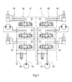
- FIG. 3 shows a device unit 1B according to the second embodiment of the present invention.
- the device unit 1B includes a first device 4A and a second device 4B that are connected to each other.
- the device unit 1B may include three or more devices connected to each other.
- each of the first device 4A and the second device 4B is a multi-control valve that includes a plurality of spools 42 that change the passage flow rate according to the command current, as shown in FIG.
- each of the first device 4A and the second device 4B includes a casing 41 that is independent of each other.
- Each casing 41 is, for example, a hexahedron having six side surfaces.
- One side surface of the casing 41 of the first device 4A and one side surface of the casing 21 of the second device 4B are in surface contact.
- each spool 42 controls the amount of hydraulic fluid supplied from the hydraulic pump to the hydraulic actuator and the amount of hydraulic fluid discharged from the hydraulic actuator to the tank.
- the hydraulic actuator may be a hydraulic cylinder or a hydraulic pump.
- Each drive mechanism pair operates the corresponding spool 42 in one direction and the other direction according to the command current.
- Each drive mechanism pair may be an electromagnetic proportional valve that outputs a secondary pressure as a pilot pressure to the corresponding spool 42.
- each drive mechanism pair may be a solenoid that presses the corresponding spool 42.
- a pump port 43 and a tank port 44 are provided on one side surface (lower surface in FIG. 3) of the casing 41 of each of the first device 4A and the second device 4B.
- a plurality of actuator ports 45 are provided on two side surfaces (the right surface and the left surface in FIG. 3) of the casing 41 of each of the first device 4A and the second device 4B.
- the number of hydraulic circuits and actuator ports 45 shown in FIG. 5 can be changed as appropriate.
- a first recording medium 33 and a second recording medium 34 are attached to one side surface (front surface in FIG. 1) of the casing 41 of the first device 4A so as to be adjacent to each other.
- the first recording medium 33 and the second recording medium 34 may be attached adjacent to one side surface of the casing 41 of the second device 4B.
- the characteristic data of the first device 4A is recorded on the first recording medium 33 with a barcode
- the characteristic data of the second device 4B is recorded on the second recording medium 34 with a barcode
- the barcode is a matrix type two-dimensional code (QR code (registered trademark)).
- the first recording medium 33 and the second recording medium 34 are separate. However, the first recording medium 33 and the second recording medium 34 may be integrated. In this case, a single object can be used as the two recording media 33 and 34.
- the attachment of the first recording medium 33 and the second recording medium 34 to the casing 41 may be, for example, affixed with an adhesive or a double-sided tape, or may be screwed.
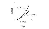
- Each of the characteristic data of the first device 4A and the characteristic data of the second device 4B described above is a relationship between the command current and the passing flow rate in each spool 42 as shown in FIG.
- the relationship between the command current and the passing flow rate exists for each operation direction of the spool 42.
- the characteristic data is discrete data as indicated by a plurality of points in FIG. 4 and is measured at the factory before shipping the corresponding device (4A or 4B). In addition, when the device is repaired (for example, part replacement), the characteristic data is also remeasured.
- the date when the characteristic data of the corresponding device (4A or 4B) is measured is also recorded in a visible manner. Further, identification data (individual product number) of the corresponding device (4A or 4B) is also recorded in each of the first recording medium 33 and the second recording medium 34.
- the equipment unit 1B is mounted on, for example, a construction machine (such as a hydraulic excavator or a hydraulic crane) or an industrial machine. And the 1st apparatus 4A and the 2nd apparatus 4B are controlled by the control apparatus of those machines. For example, the control device sends a command current to the drive mechanism pair of the first device 4A and the drive mechanism pair of the second device 4B in accordance with the operation amount of the operation device operated by the user.
- the characteristic data of the first device 4A recorded on the first recording medium 33 and the characteristic data of the second device 4B recorded on the second recording medium 34 are read by a bar code reader and input to the above-described machine control device. Is done.
- the control device electronically calibrates variations in characteristics of the first device 4A and the second device 4B. For example, the control device feeds the drive mechanism pair of the first device 4A and the drive mechanism pair of the second device 4B so that a set passage flow rate corresponding to the operation amount of the operation device operated by the user is obtained. Adjust the command current.
- the characteristic data of the first device 4A is recorded on the first recording medium 33
- the characteristic data of the second device 4B is recorded on the second recording medium 34. Therefore, the characteristic data of the first device 4A and the second device 4B can be directly read. Moreover, since the first recording medium 33 and the second recording medium 34 are attached adjacent to one side surface of the casing of the first device 4A, the characteristic data of the first device 4A and the second device 4B can be obtained for a short time. Can be read efficiently.
- the storage destination IP address of the characteristic data of the first device 2A is recorded in the first recording medium 31, and the storage destination IP address of the characteristic data of the second device 2B is stored in the second recording medium 32. It is also possible to record. In this case, recording of the storage destination IP address on each recording medium does not have to be performed by a barcode, and may be performed by printing, for example.
- the characteristic data of each device can be read via the Internet. Furthermore, with this configuration, a large amount of characteristic data can be stored in the server or terminal, so that variations in device characteristics can be accurately calibrated. Note that the modification of recording the characteristic data storage destination IP address on the recording medium is also applicable to the second embodiment.
Landscapes
- Engineering & Computer Science (AREA)
- General Engineering & Computer Science (AREA)
- Physics & Mathematics (AREA)
- Mechanical Engineering (AREA)
- General Physics & Mathematics (AREA)
- Theoretical Computer Science (AREA)
- Electromagnetism (AREA)
- Health & Medical Sciences (AREA)
- General Health & Medical Sciences (AREA)
- Toxicology (AREA)
- Artificial Intelligence (AREA)
- Computer Vision & Pattern Recognition (AREA)
- Automation & Control Theory (AREA)
- Computer Hardware Design (AREA)
- Valve Housings (AREA)
- Fluid-Pressure Circuits (AREA)
- Control Of Positive-Displacement Pumps (AREA)
- Management, Administration, Business Operations System, And Electronic Commerce (AREA)
Priority Applications (2)
| Application Number | Priority Date | Filing Date | Title |
|---|---|---|---|
| CN201980027106.1A CN111989515B (zh) | 2018-06-01 | 2019-05-28 | 机器单元 |
| US15/734,161 US20210216051A1 (en) | 2018-06-01 | 2019-05-28 | Apparatus unit |
Applications Claiming Priority (2)
| Application Number | Priority Date | Filing Date | Title |
|---|---|---|---|
| JP2018106042A JP7037440B2 (ja) | 2018-06-01 | 2018-06-01 | 機器ユニット |
| JP2018-106042 | 2018-06-01 |
Publications (1)
| Publication Number | Publication Date |
|---|---|
| WO2019230681A1 true WO2019230681A1 (ja) | 2019-12-05 |
Family
ID=68696975
Family Applications (1)
| Application Number | Title | Priority Date | Filing Date |
|---|---|---|---|
| PCT/JP2019/020995 Ceased WO2019230681A1 (ja) | 2018-06-01 | 2019-05-28 | 機器ユニット |
Country Status (4)
| Country | Link |
|---|---|
| US (1) | US20210216051A1 (enExample) |
| JP (1) | JP7037440B2 (enExample) |
| CN (1) | CN111989515B (enExample) |
| WO (1) | WO2019230681A1 (enExample) |
Families Citing this family (3)
| Publication number | Priority date | Publication date | Assignee | Title |
|---|---|---|---|---|
| JP2023131855A (ja) * | 2022-03-10 | 2023-09-22 | 川崎重工業株式会社 | コントローラおよびキャリブレーションシステム |
| JP2022140429A (ja) * | 2022-03-28 | 2022-09-26 | 川崎重工業株式会社 | プログラム |
| JP2024071104A (ja) * | 2022-11-14 | 2024-05-24 | 川崎重工業株式会社 | ポンプ装置 |
Citations (2)
| Publication number | Priority date | Publication date | Assignee | Title |
|---|---|---|---|---|
| JP2002180897A (ja) * | 2000-12-13 | 2002-06-26 | Denso Corp | 内燃機関の調整方法 |
| JP2006114525A (ja) * | 2004-09-15 | 2006-04-27 | Nachi Fujikoshi Corp | ソレノイド部材の特性補正装置及びソレノイド部材 |
Family Cites Families (12)
| Publication number | Priority date | Publication date | Assignee | Title |
|---|---|---|---|---|
| US6097171A (en) * | 1998-01-30 | 2000-08-01 | A. O. Smith Corporation | Method and apparatus for controlling an induction motor |
| DE10153625A1 (de) * | 2000-11-02 | 2002-07-11 | Denso Corp | Vorrichtung zur Steuerung einer Brennkraftmaschine, diese Maschinensteuervorrichtung verwendendes Datenkommunikationssystem, Steuerdatenbereitstellungssystem für ein Maschinensteuersystem, zugehöriges Maschineneinstellverfahren und Einspritzeinrichtungsdatenlesevorrichtung |
| US6986646B2 (en) * | 2002-04-12 | 2006-01-17 | Caterpillar Inc. | Electronic trim for a variable delivery pump in a hydraulic system for an engine |
| JP2006083959A (ja) * | 2004-09-16 | 2006-03-30 | Fujikin Inc | センサ付き継手部材 |
| CN102483056B (zh) * | 2010-05-20 | 2014-07-02 | 株式会社小松制作所 | 作业车辆及作业车辆的控制方法 |
| DE102012105951A1 (de) * | 2012-03-30 | 2013-10-02 | Pfeiffer Vacuum Gmbh | Pumpensystem zur Evakuierung von Gas aus einer Mehrzahl von Kammern sowie Verfahren zur Steuerung des Pumpensystems |
| TWI496096B (zh) * | 2012-05-31 | 2015-08-11 | Toshiba Global Commerce Solutions Holdings Corp | 在一物品區域中管理複數物品的系統、方法、與儲放單元 |
| WO2014080351A1 (en) * | 2012-11-26 | 2014-05-30 | Fisher & Paykel Healthcare Limited | Transfer of breathing assistance apparatus data |
| US10316849B2 (en) * | 2014-10-15 | 2019-06-11 | Grundfos Holding A/S | Method and system for detection of faults in pump assembly via handheld communication device |
| US11085440B2 (en) * | 2015-09-02 | 2021-08-10 | Project Phoenix, LLC | System to pump fluid and control thereof |
| CA2930323C (en) * | 2016-05-17 | 2023-11-14 | Op-Hygiene Ip Gmbh | Superimposed qr code for dispenser and replaceable reservoir |
| CN207246512U (zh) * | 2017-09-15 | 2018-04-17 | 广州智特信息科技有限公司 | 带电子信息标签的角阀 |
-
2018
- 2018-06-01 JP JP2018106042A patent/JP7037440B2/ja active Active
-
2019
- 2019-05-28 CN CN201980027106.1A patent/CN111989515B/zh active Active
- 2019-05-28 US US15/734,161 patent/US20210216051A1/en not_active Abandoned
- 2019-05-28 WO PCT/JP2019/020995 patent/WO2019230681A1/ja not_active Ceased
Patent Citations (2)
| Publication number | Priority date | Publication date | Assignee | Title |
|---|---|---|---|---|
| JP2002180897A (ja) * | 2000-12-13 | 2002-06-26 | Denso Corp | 内燃機関の調整方法 |
| JP2006114525A (ja) * | 2004-09-15 | 2006-04-27 | Nachi Fujikoshi Corp | ソレノイド部材の特性補正装置及びソレノイド部材 |
Also Published As
| Publication number | Publication date |
|---|---|
| JP2019210974A (ja) | 2019-12-12 |
| JP7037440B2 (ja) | 2022-03-16 |
| US20210216051A1 (en) | 2021-07-15 |
| CN111989515B (zh) | 2022-09-16 |
| CN111989515A (zh) | 2020-11-24 |
Similar Documents
| Publication | Publication Date | Title |
|---|---|---|
| WO2019230681A1 (ja) | 機器ユニット | |
| Lindler et al. | Piezoelectric direct drive servovalve | |
| US20030125840A1 (en) | System and method for controlling hydraulic flow | |
| CN110686586A (zh) | 检测由螺线管线性致动器驱动的阀门位置的系统和方法 | |
| CN105840566B (zh) | 用于为至少两个液压负载供应压力介质的液压控制装置 | |
| US20230136445A1 (en) | Servoless motor | |
| JP2015105676A5 (enExample) | ||
| EP3663580B1 (en) | Hydraulic drive apparatus | |
| KR20190014062A (ko) | 유량 제어 밸브 장치 | |
| US10443629B2 (en) | Operation device and hydraulic system | |
| JP4198115B2 (ja) | サーボ・弁制御装置 | |
| WO2019044616A1 (ja) | 電磁弁識別装置、及びそれを備える制御ユニット | |
| JP2013019425A (ja) | 液圧装置 | |
| CN113048105B (zh) | 致动器控制装置 | |
| JP2024065399A (ja) | 液圧ポンプの性能低下検知システム | |
| CN118836146A (zh) | 控制器及泵系统 | |
| US4561470A (en) | Servo valve control device | |
| CN221220763U (zh) | 泵装置 | |
| WO2023171029A1 (ja) | コントローラおよびキャリブレーションシステム | |
| JP2001311401A (ja) | 液圧サーボバルブの制御方法および装置並びに液圧シリンダの駆動方法および装置 | |
| RU2780434C1 (ru) | Пропорциональный электрогидравлический распределитель непрямого действия | |
| DUȚU et al. | Study on the Use of Digital Hydraulics in PET Waste Baling Presses. | |
| EP3279530A1 (en) | Direct-operated hydraulic servo valves | |
| Backé et al. | Fluidpower Actuators | |
| JP2024035295A (ja) | 液圧ポンプの性能低下検知システム |
Legal Events
| Date | Code | Title | Description |
|---|---|---|---|
| 121 | Ep: the epo has been informed by wipo that ep was designated in this application |
Ref document number: 19812178 Country of ref document: EP Kind code of ref document: A1 |
|
| NENP | Non-entry into the national phase |
Ref country code: DE |
|
| 122 | Ep: pct application non-entry in european phase |
Ref document number: 19812178 Country of ref document: EP Kind code of ref document: A1 |