WO2019230673A1 - 摩擦材及び摩擦材組成物 - Google Patents
摩擦材及び摩擦材組成物 Download PDFInfo
- Publication number
- WO2019230673A1 WO2019230673A1 PCT/JP2019/020978 JP2019020978W WO2019230673A1 WO 2019230673 A1 WO2019230673 A1 WO 2019230673A1 JP 2019020978 W JP2019020978 W JP 2019020978W WO 2019230673 A1 WO2019230673 A1 WO 2019230673A1
- Authority
- WO
- WIPO (PCT)
- Prior art keywords
- abrasive
- composition
- mohs hardness
- friction material
- friction
- Prior art date
- Legal status (The legal status is an assumption and is not a legal conclusion. Google has not performed a legal analysis and makes no representation as to the accuracy of the status listed.)
- Ceased
Links
Images

Classifications
-
- F—MECHANICAL ENGINEERING; LIGHTING; HEATING; WEAPONS; BLASTING
- F16—ENGINEERING ELEMENTS AND UNITS; GENERAL MEASURES FOR PRODUCING AND MAINTAINING EFFECTIVE FUNCTIONING OF MACHINES OR INSTALLATIONS; THERMAL INSULATION IN GENERAL
- F16D—COUPLINGS FOR TRANSMITTING ROTATION; CLUTCHES; BRAKES
- F16D69/00—Friction linings; Attachment thereof; Selection of coacting friction substances or surfaces
- F16D69/02—Composition of linings ; Methods of manufacturing
- F16D69/025—Compositions based on an organic binder
- F16D69/026—Compositions based on an organic binder containing fibres
-
- F—MECHANICAL ENGINEERING; LIGHTING; HEATING; WEAPONS; BLASTING
- F16—ENGINEERING ELEMENTS AND UNITS; GENERAL MEASURES FOR PRODUCING AND MAINTAINING EFFECTIVE FUNCTIONING OF MACHINES OR INSTALLATIONS; THERMAL INSULATION IN GENERAL
- F16D—COUPLINGS FOR TRANSMITTING ROTATION; CLUTCHES; BRAKES
- F16D2200/00—Materials; Production methods therefor
- F16D2200/0004—Materials; Production methods therefor metallic
-
- F—MECHANICAL ENGINEERING; LIGHTING; HEATING; WEAPONS; BLASTING
- F16—ENGINEERING ELEMENTS AND UNITS; GENERAL MEASURES FOR PRODUCING AND MAINTAINING EFFECTIVE FUNCTIONING OF MACHINES OR INSTALLATIONS; THERMAL INSULATION IN GENERAL
- F16D—COUPLINGS FOR TRANSMITTING ROTATION; CLUTCHES; BRAKES
- F16D2200/00—Materials; Production methods therefor
- F16D2200/0034—Materials; Production methods therefor non-metallic
- F16D2200/0039—Ceramics
- F16D2200/0043—Ceramic base, e.g. metal oxides or ceramic binder
-
- F—MECHANICAL ENGINEERING; LIGHTING; HEATING; WEAPONS; BLASTING
- F16—ENGINEERING ELEMENTS AND UNITS; GENERAL MEASURES FOR PRODUCING AND MAINTAINING EFFECTIVE FUNCTIONING OF MACHINES OR INSTALLATIONS; THERMAL INSULATION IN GENERAL
- F16D—COUPLINGS FOR TRANSMITTING ROTATION; CLUTCHES; BRAKES
- F16D2200/00—Materials; Production methods therefor
- F16D2200/006—Materials; Production methods therefor containing fibres or particles
- F16D2200/0069—Materials; Production methods therefor containing fibres or particles being characterised by their size
Definitions
- the present invention relates to a friction material and a friction material composition.
- JP 2014-122314 A Japanese Patent No. 6233461
- the mating material is more aggressive. There was a risk of increasing the amount of wear.
- the frictional surface cleaning action is low, excessive film formation and mirroring progress, and in high humidity environments, the friction coefficient increases greatly, causing squealing and braking force greater than the optimum braking force during braking. As a result, there is a risk that the front end side of the vehicle will sink suddenly and return suddenly.
- an object of the present invention is to provide a friction material and a friction material composition capable of maintaining a desired friction coefficient.
- the friction member of the embodiment is a friction material having a copper blending amount of 0.5% by weight or less, having a cleavage property, and an inorganic material having a blending amount of 10 to 20 wt%. And a first abrasive with a Mohs hardness of 6.5 or more and less than 7, and a second abrasive with a Mohs hardness of 7 or more and 8 or less and a blending amount of 0.2 to 3 wt%. According to the above configuration, an appropriate abrasive force can be obtained, the smoothing of the friction surface can be suppressed, and fluctuations in the friction coefficient due to environmental changes and braking conditions can be suppressed.
- the friction material composition of the embodiment is a friction material composition in which the blending amount of copper is 0.5% by weight or less, and includes a fiber base material, a friction modifier, and a thermosetting binder.
- a second abrasive having a compounding amount of 0.2 to 3 wt%.
- FIG. 1 is an external perspective view of a brake pad according to an embodiment.
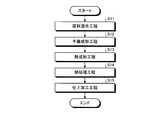
- Drawing 2 is an explanatory view of the manufacturing method of the brake pad using the friction material of an embodiment.
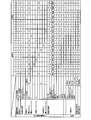
- FIG. 3 is an explanatory diagram of the performance evaluation results of Examples and Comparative Examples.
- FIG. 1 is an external perspective view of a brake pad according to an embodiment.
- the brake pad 10 is in contact with the back plate 11 having the first surface F1 and the first surface F1, is located on the opposite side of the first surface F1 with respect to the center in the thickness direction, and is substantially parallel to the first surface F1.
- the friction material having a copper blending amount of 0.5% by weight or less, having an cleavage property, and having a blending amount of 10 to 20 wt%, Mohs hardness
- a first abrasive having a hardness of 6.5 or more and less than 7 and a second abrasive having a Mohs hardness of 7 or more and 8 or less and a blending amount of 0.2 to 3 wt% are provided.
- the first abrasive can remove the rust of the mating member such as the rotor and obtain the desired friction coefficient ⁇
- the second abrasive can obtain the desired abrasive force and the friction surface. Therefore, the friction coefficient ⁇ can be stabilized due to environmental changes and braking conditions.
- the second abrasive is constituted by a plurality of types of abrasives, a stable abrasive force can be obtained under more various use conditions. Furthermore, by setting the average particle size of the second abrasive to less than 10 ⁇ m (more preferably 1 to 3 ⁇ m), it is possible to obtain an optimum abrasive force while suppressing excessive aggressiveness against a mating material such as a rotor. Can do.
- the blending amount of the first abrasive is 0.2 to 1 wt%, an appropriate friction coefficient ⁇ can be obtained. Furthermore, by setting the average particle diameter of the first abrasive to 10 ⁇ m or more, it is possible to reliably reduce the rust of the counterpart material such as the rotor and maintain the optimum friction coefficient ⁇ .
- FIG. 2 is a process explanatory diagram of a brake pad manufacturing method using the friction material of the embodiment.
- a predetermined raw material is mixed to obtain a mixed powder (friction material composition) (step S11).
- the predetermined raw material here is a fiber base material, a binder, an organic filler, an abrasive, an inorganic filler containing a cleaved inorganic material, or the like.
- the fiber base material include aramid fibers and inorganic fibers.
- the phenol resin which is a thermosetting resin is mentioned.
- organic filler examples include cashew dust and rubber powder (SBR).
- SBR cashew dust and rubber powder
- abrasive chromium oxide having a Mohs hardness of 6.5 (corresponding to the first abrasive), zirconium oxide having a Mohs hardness of 7 (corresponding to the second abrasive), and a Mohs hardness of 7.5.
- Zirconium silicate corresponding to the second abrasive
- zirconium boride having a Mohs hardness of 8 corresponding to the second abrasive
- Mohs hardness of 8 media porcelain powder (corresponding to the second abrasive), etc. .
- the first abrasive has a braking function by removing rust on the rotor surface against which the brake pad comes into contact or obtaining a predetermined friction coefficient ⁇ .
- the second abrasive has a function for scraping the rotor surface with an abrasive force and suppressing the smoothing of the rotor to stabilize the friction coefficient ⁇ .
- the inorganic filler examples include barium sulfate, cleaved inorganic material that functions as a lubricant, graphite, graphite, and slaked lime (calcium hydroxide) that functions as a pH adjuster.
- examples of the inorganic filler include tin sulfide, potassium titanate, and iron oxide that function as an inorganic friction modifier.
- preforming is performed by a preforming process (step S12).
- molding is performed to such an extent that the friction material mixture can be placed on a predetermined back plate.
- This thermoforming is performed in order to maintain the shape of the lining (or brake pad) in a heat treatment performed later, after sufficiently dissolving the binder (binder) added as a raw material and then curing.
- a predetermined raw material is put into the mold in a state where the back plate 21 is placed in the mold, and pressurization and heating are performed.
- step S15 the brake pad 20 after the heat treatment is subjected to a predetermined finishing process (step S15) to become a product.
- the brake pad 20 includes an inorganic material having a cleavage property and a blending amount of 10 to 20 wt%, a first abrasive having a Mohs hardness of 6.5 or more and less than 7, and Mohs Since the second abrasive having a hardness of 7 to 8 and a blending amount of 0.2 to 3 wt% is included, smoothing of the friction material and the counterpart material (for example, the rotor) is suppressed, It is possible to increase the stability of the friction coefficient ⁇ by suppressing changes in the friction coefficient ⁇ due to environmental changes and braking conditions.
- FIG. 3 is an explanatory diagram of examples, comparative examples, and performance evaluation.
- the composition of the first example will be described in detail.
- 5% by weight of aramid fiber was blended as a fiber base material.
- 9 wt% of phenol resins were mix
- 4 wt% of cashew dust and 2 wt% of rubber powder (SBR) were blended as organic fillers.
- chromium oxide with a Mohs hardness of 6.5 (average particle diameter: 10 ⁇ m) is used as the first abrasive
- zirconium silicate with an Mohs hardness of 7.5 (average particle) is used as the second abrasive.
- tin sulfide 21 wt% potassium titanate, 9 wt% iron oxide, 5 wt% graphite, 15 wt% mica, and 3 wt% slaked lime are used as the inorganic filler.
- Barium sulfate was blended to make a total of 100 wt%.
- composition of the second example is different from the composition of the first example in that the composition of the abrasive is chromium oxide with a Mohs hardness of 6.5 as the first abrasive ( 0.5 wt% of the average particle diameter of 10 ⁇ m) and 2.5 wt% of zirconium oxide having a Mohs hardness of 7 (average particle diameter of 1 ⁇ m) as the second abrasive.
- Other blending compositions are the same as in the first embodiment.
- composition of the third example is that, with respect to the composition of the abrasive, chromium oxide having a Mohs hardness of 6.5 as the first abrasive ( 0.5 wt% of the average particle diameter of 10 ⁇ m) and 2.5 wt% of zirconium oxide having a Mohs hardness of 7 (average particle diameter of 3 ⁇ m) as the second abrasive.
- Other blending compositions are the same as in the first embodiment.
- composition of the fourth example is chromium oxide with Mohs' hardness of 6.5 as the first abrasive ( 0.5 wt% of the average particle diameter of 10 ⁇ m) and 2.5 wt% of zirconium silicate having a Mohs hardness of 7.5 (average particle diameter of 1 ⁇ m) as the second abrasive.
- Other blending compositions are the same as in the first embodiment.
- the blending composition of the fifth example differs from the blending composition of the first example with respect to the blending of the abrasives.
- a first abrasive chromium oxide having a Mohs hardness of 6.5 ( 0.5 wt% of the average particle diameter of 10 ⁇ m) and 2.5 wt% of zirconium silicate having a Mohs hardness of 7.5 (average particle diameter of 3 ⁇ m) as the second abrasive.
- Other blending compositions are the same as in the first embodiment.
- composition of the sixth example is different from the composition of the first example in that the composition of the abrasive is chromium oxide (Mohs hardness 6.5) as the first abrasive. 0.5 wt% of the average particle diameter (10 ⁇ m) and 2.5 wt% of zirconium silicate having a Mohs hardness of 7.5 (average particle diameter of 10 ⁇ m) as the second abrasive. Other blending compositions are the same as in the first embodiment.
- composition of the seventh example is different from the composition of the first example in that chromium oxide having a Mohs hardness of 6.5 (average particle size of 10 ⁇ m) is used as the first abrasive. This is a point in which 2.5 wt% of ceramic powder (average particle diameter of 3 ⁇ m) having a Mohs hardness of 8 is blended as the second abrasive. Other blending compositions are the same as in the first embodiment.
- the compounding composition of the eighth example is different from the compounding composition of the first example in that chromium oxide having a Mohs hardness of 6.5 (average particle diameter of 10 ⁇ m) is used as the first abrasive. This is a point where 0.5 wt% and 3 wt% of zirconium silicate (average particle diameter of 1 ⁇ m) having a Mohs hardness of 7.5 are blended as the second abrasive. Other blending compositions are the same as in the first embodiment.
- the composition of the ninth example is different from that of the first example in that chromium oxide having a Mohs hardness of 6.5 (average particle size of 10 ⁇ m) is used as the first abrasive.
- Comparative Example Next, a comparative example will be described.
- the blending composition of the comparative example is roughly divided into a fiber base material, a binder, an organic filler, an abrasive, and an inorganic filler as in the blending composition of the examples.
- composition of the third comparative example is different from the composition of the first embodiment described above in that zirconium oxide having a Mohs hardness of 7 (average particle diameter of 1 ⁇ m) is used for the blending of the abrasive. It is the point which mix
- Other blending compositions are the same as in the first embodiment.
- the fifth comparative example is different from the above-mentioned first embodiment in that the composition of the fifth comparative example is chromium oxide having a Mohs hardness of 6.5 (average particle diameter of 10 ⁇ m) with respect to the composition of the abrasive. ) 0.3 wt% and Mohs hardness 7.5 zirconium silicate (average particle diameter 3 ⁇ m) was blended 5 wt%. Other blending compositions are the same as in the first embodiment.
- the wear amount of the brake pad was determined to be ⁇ (good) when it was less than 1 mm, ⁇ (possible) from 1 mm to 1.5 mm, and (not possible) exceeding 1.5 mm.
- the rotor wear amount was evaluated as ⁇ (good) when the wear amount of the rotor was less than 10 ⁇ m, ⁇ (possible) when 10 ⁇ m to 20 ⁇ m, and (impossible) when 20 ⁇ m was exceeded.
- the sixth comparative example has a problem in moldability, and in the first comparative example to the seventh comparative example excluding the sixth comparative example, any one of the deceleration spread, the low surface pressure aggression property, or the effect according to the environment It has been found that there is a possibility that a practical problem may occur.
- the Mohs hardness is 6.5 or more and less than 7 It can be seen that it is effective to provide both the first abrasive and the second abrasive having a Mohs hardness of 7 or more and 8 or less.
- the blending amount of the first abrasive having a Mohs hardness of 6.5 or more and less than 7 is preferably 0.2 to 1 wt%. From the results of the items of speed spread and environmental effect, it was considered that 0.5 to 1 wt% is more preferable.
- the Mohs hardness of the second abrasive that exhibits the abrasive force is 7 to 8 according to the results of the sixth and seventh examples. Therefore, it was considered that the average particle size should be less than 10 ⁇ m, more preferably 1 to 3 ⁇ m.
- the disc brake 1 is a floating type
- the piston as the pressing member is disposed opposite to each other, and the opposed piston serves as a pair of brake pad pads.
- the present invention can be similarly applied to a so-called opaque type (opposed piston type) configured to be pressed against the friction material.
- the brake pad (lining) for the disc brake has been described.
- the present invention can also be applied to a brake shoe of a drum brake that comes into contact with the brake drum (friction material).
Landscapes
- Engineering & Computer Science (AREA)
- General Engineering & Computer Science (AREA)
- Mechanical Engineering (AREA)
- Braking Arrangements (AREA)
Abstract
実施形態の摩擦材は、銅の配合量が0.5重量%以下の摩擦材であって、劈開性を有し、配合量が10~20wt%とされた無機材と、モース硬度6.5以上7未満の第1の研削材と、モース硬度7以上8以下であって、配合量が0.2~3wt%の第2の研削材と、を備える。
Description
本発明は、摩擦材及び摩擦材組成物に関する。
近年、河川汚染、海洋汚染あるいは人体への悪影響などの観点から、ブレーキパッドに含まれる素材への環境適合性の要求も厳しくなりつつある。
このため、銅を含有しない(あるいは銅含有量を低減した)ブレーキパッド(摩擦材)の開発が望まれている。
このため、銅を含有しない(あるいは銅含有量を低減した)ブレーキパッド(摩擦材)の開発が望まれている。
しかしながら、上記従来の銅を含有しない(あるいは銅含有量を低減した)ブレーキパッド(摩擦材)においては、研削材の種類あるいはロータ等の相手材によっては、相手材攻撃性が高くなり、相手材の摩耗量を大きくしてしまう虞があった。
また、摩擦面のクリーニング作用が低く、過剰な被膜形成と鏡面化が進行して、高湿度環境下では、摩擦係数が大きく上昇して、鳴きや、制動時に最適な制動力よりも大きな制動力がかかり、車両前端側が急激に沈み込み、急激に戻る状態が発生する虞があった。
また、摩擦面のクリーニング作用が低く、過剰な被膜形成と鏡面化が進行して、高湿度環境下では、摩擦係数が大きく上昇して、鳴きや、制動時に最適な制動力よりも大きな制動力がかかり、車両前端側が急激に沈み込み、急激に戻る状態が発生する虞があった。
そこで、本発明は、銅を含有しない(あるいは銅含有量を低減した)摩擦材において、適度なアブレーシブ力が得られ、摩擦面の平滑化及び環境変化や制動条件による摩擦係数の変動を抑制して、所望の摩擦係数に維持することが可能な摩擦材及び摩擦材組成物を提供することを目的としている。
上記課題を解決するため、実施形態の摩擦部材は、銅の配合量が0.5重量%以下の摩擦材であって、劈開性を有し、配合量が10~20wt%とされた無機材と、モース硬度6.5以上7未満の第1の研削材と、モース硬度7以上8以下であって、配合量が0.2~3wt%の第2の研削材と、を備える。
上記構成によれば、適度なアブレーシブ力が得られ、摩擦面の平滑化を抑制して、環境変化や制動条件による摩擦係数の変動を抑制できる。
上記構成によれば、適度なアブレーシブ力が得られ、摩擦面の平滑化を抑制して、環境変化や制動条件による摩擦係数の変動を抑制できる。
また、実施形態の摩擦材用組成物は、銅の配合量が0.5重量%以下の摩擦材用組成物であって、繊維基材と、摩擦調整材と、熱硬化性の結合材と、充填材と、劈開性を有し、配合量が10~20wt%とされた無機材と、モース硬度6.5以上7未満の第1の研削材と、モース硬度7以上8以下であって、配合量が0.2~3wt%の第2の研削材と、を含む。
上記構成によれば、適度なアブレーシブ力が得られ、摩擦面の平滑化を抑制して、環境変化や制動条件による摩擦係数の変動を抑制できる摩擦材が得られる。
上記構成によれば、適度なアブレーシブ力が得られ、摩擦面の平滑化を抑制して、環境変化や制動条件による摩擦係数の変動を抑制できる摩擦材が得られる。
次に図面を参照して本発明の例示的な実施形態について詳細に説明する。
以下に示される実施形態の構成、ならびに当該構成によってもたらされる作用および結果(効果)は、一例である。本発明は、以下の実施形態に開示される構成以外によっても実現可能である。また、本発明によれば、構成によって得られる種々の効果(派生的な効果も含む)のうち少なくとも一つを得ることが可能である。
以下に示される実施形態の構成、ならびに当該構成によってもたらされる作用および結果(効果)は、一例である。本発明は、以下の実施形態に開示される構成以外によっても実現可能である。また、本発明によれば、構成によって得られる種々の効果(派生的な効果も含む)のうち少なくとも一つを得ることが可能である。
図1は、実施形態のブレーキパッドの外観斜視図である。
ブレーキパッド10は、第一面F1を有した裏板11と、第一面F1と接し、厚さ方向の中央に対して第一面F1と反対側に位置され第一面F1と略平行な第二面F2を有したライニング12と、を備えている。
ブレーキパッド10は、第一面F1を有した裏板11と、第一面F1と接し、厚さ方向の中央に対して第一面F1と反対側に位置され第一面F1と略平行な第二面F2を有したライニング12と、を備えている。
まず、実施形態の原理について説明する。
環境負荷の低減を図るために銅の配合量が0.5重量%以下の摩擦材を構成する場合、低温での摩擦係数が低下(悪化)する。
環境負荷の低減を図るために銅の配合量が0.5重量%以下の摩擦材を構成する場合、低温での摩擦係数が低下(悪化)する。
これを回避するため劈開性を有する無機材として、マイカを添加し、3wt%以下の研削材を組み合わせることで、適度な摩擦係数μが得られるとともに、ロータ等の相手材への攻撃性を抑制して、肉厚差成長を抑制することが知られている。
しかしながら、銅の配合量及び研削材の配合量が少ないため、摩擦面が平滑化され、高湿度時に摩擦係数の過度な上昇が生じる虞があった。
またアブレーシブ力の不足により高速高加圧時の摩擦係数μの低下や、相手材の錆落とし性の低下が発生する虞もあった。
またアブレーシブ力の不足により高速高加圧時の摩擦係数μの低下や、相手材の錆落とし性の低下が発生する虞もあった。
これを避けるため、本実施形態では、銅の配合量が0.5重量%以下の摩擦材であって、劈開性を有し、配合量が10~20wt%とされた無機材と、モース硬度6.5以上7未満の第1の研削材と、モース硬度7以上8以下であって、配合量が0.2~3wt%の第2の研削材と、を備えることとした。
この構成によれば、第1の研削材によりロータ等の相手材の錆を落とし、所望の摩擦係数μを得ることができるとともに、第2の研削材により所望のアブレーシブ力が得られて摩擦面の平滑化を抑制し、環境変化や制動条件による摩擦係数μの安定化を図ることができるのである。
この場合において、第2の研削材を、複数種類の研削材で構成するようにすれば、より様々な使用条件下で安定したアブレーシブ力を得ることができる。
さらに第2の研削材の平均粒子径は、10μm未満(より好ましくは、1~3μm)とすることで、ロータ等の相手材に対する過度な攻撃性を抑制しつつ、最適なアブレーシブ力を得ることができる。
さらに第2の研削材の平均粒子径は、10μm未満(より好ましくは、1~3μm)とすることで、ロータ等の相手材に対する過度な攻撃性を抑制しつつ、最適なアブレーシブ力を得ることができる。
また、第1の研削材の配合量が0.2~1wt%とすることで適度な摩擦係数μとすることができる。
さらに、第1の研削材の平均粒子径は、10μm以上とすることにより、ロータ等の相手材の錆を確実に落として、最適な摩擦係数μを維持することができる。
さらに、第1の研削材の平均粒子径は、10μm以上とすることにより、ロータ等の相手材の錆を確実に落として、最適な摩擦係数μを維持することができる。
すなわち、本実施形態によれば、摩擦面において最適な摩擦係数μを得ることが可能な状態に維持するとともに、所望のアブレーシブ力が得られて摩擦面の平滑化を抑制し、環境変化や制動条件による摩擦係数μの安定化を図ることが可能となる。
次により具体的な摩擦材(ライニング)を含むブレーキパッドの製造方法について説明する。
図2は、実施形態の摩擦材を用いたブレーキパッドの製造方法の処理説明図である。
所定の原料を混合して混合粉(摩擦材組成物)を得る(ステップS11)。
図2は、実施形態の摩擦材を用いたブレーキパッドの製造方法の処理説明図である。
所定の原料を混合して混合粉(摩擦材組成物)を得る(ステップS11)。
ここでいう所定の原料とは、繊維基材、結合材、有機充填材、研削材及び劈開性を有する無機材を含む無機充填材等である。
この場合において、繊維基材としては、アラミド繊維、無機繊維等が挙げられる。
また、結合材としては、熱硬化性樹脂であるフェノール樹脂が挙げられる。
この場合において、繊維基材としては、アラミド繊維、無機繊維等が挙げられる。
また、結合材としては、熱硬化性樹脂であるフェノール樹脂が挙げられる。
有機充填材(有機摩擦調整材)としては、カシューダスト、ゴム粉(SBR)等が挙げられる。
また、研削材としては、モース硬度6.5である酸化クロム(第1の研削材に相当)、モース硬度7である酸化ジルコニウム(第2の研削材に相当)、モース硬度7.5である珪酸ジルコニウム(第2の研削材に相当)、モース硬度8であるホウ化ジルコニウム(第2の研削材に相当)や同じくモース硬度8ディア磁器粉末(第2の研削材に相当)等が挙げられる。
また、研削材としては、モース硬度6.5である酸化クロム(第1の研削材に相当)、モース硬度7である酸化ジルコニウム(第2の研削材に相当)、モース硬度7.5である珪酸ジルコニウム(第2の研削材に相当)、モース硬度8であるホウ化ジルコニウム(第2の研削材に相当)や同じくモース硬度8ディア磁器粉末(第2の研削材に相当)等が挙げられる。
上記研削材において、第1の研削材は、ブレーキパッドが当接するロータ表面の錆を落としたり、所定の摩擦係数μを得たりして、制動の機能を有する。
一方、第2の研削材は、アブレーシブ力によりロータ表面を削り取り、ロータの平滑化を抑制して、摩擦係数μの安定化を図るための機能を有する。
一方、第2の研削材は、アブレーシブ力によりロータ表面を削り取り、ロータの平滑化を抑制して、摩擦係数μの安定化を図るための機能を有する。
無機充填材としては、硫酸バリウム、潤滑材として機能する劈開性を有する無機材であるマイカ、黒鉛、pH調整材として機能する消石灰(水酸化カルシウム)、が挙げられる。
さらに無機充填材としては、無機摩擦調整材として機能する硫化錫、チタン酸カリウム、酸化鉄等が挙げられる。
所定の原料が十分に混合された後、予備成形工程により予備成形を行う(ステップS12)。
この予備成形においては、摩擦材の混合体を所定の裏板に載置することが可能な程度の成形を行う。
この予備成形においては、摩擦材の混合体を所定の裏板に載置することが可能な程度の成形を行う。
続いて、予備成形されたライニング22を裏板21の所定位置に配置した状態で熱成形装置の加圧及び加熱用の型にセットし、第1の温度帯(=200℃未満)において熱成形を行う(ステップS13)。
この熱成形は、原料として加えてある結合材(バインダ)を十分に溶かした後に硬化させ、後段に行われる熱処理においてライニング(あるいはブレーキパッド)の形状を維持するために行われるものであり、所定の型内に裏板21を配置した状態で所定の原料を型内に投入し、加圧及び加熱を行う。
この熱成形は、原料として加えてある結合材(バインダ)を十分に溶かした後に硬化させ、後段に行われる熱処理においてライニング(あるいはブレーキパッド)の形状を維持するために行われるものであり、所定の型内に裏板21を配置した状態で所定の原料を型内に投入し、加圧及び加熱を行う。
この状態において、裏板21及びライニング22を備えたブレーキパッド20は、変形を抑制するため加圧した状態で、第1の温度帯より高い第2の温度帯(=200~240℃)において所定時間(例えば、1時間~2時間)加熱して、ライニング22を硬化させる熱処理がなされる(ステップS14)。
続いて、熱処理後のブレーキパッド20は、所定の仕上げ加工が施され(ステップS15)、製品となる。
本実施形態によれば、ブレーキパッド20には、劈開性を有し、配合量が10~20wt%とされた無機材と、モース硬度6.5以上7未満の第1の研削材と、モース硬度7以上8以下であって、配合量が0.2~3wt%の第2の研削材と、が含まれているので、摩擦材及び相手材(例えば、ロータ)の平滑化を抑制し、環境の変化や制動条件による摩擦係数μの変化を抑制して、摩擦係数μの安定性を高めることができる。
次に実施例について詳細に説明する。
図3は、実施例、比較例及び性能評価の説明図である。
[1]実施例
[1.1]第1実施例
まず第1実施例(図3中、実施例1と表す。以下同様)の配合組成について説明する。
実施例の配合組成物としては、大別すると、繊維基材、結合材、有機充填材、研削材及び無機充填材が挙げられる。
図3は、実施例、比較例及び性能評価の説明図である。
[1]実施例
[1.1]第1実施例
まず第1実施例(図3中、実施例1と表す。以下同様)の配合組成について説明する。
実施例の配合組成物としては、大別すると、繊維基材、結合材、有機充填材、研削材及び無機充填材が挙げられる。
以下、第1実施例の配合組成について詳細に説明する。
第1実施例においては、繊維基材として、アラミド繊維を5wt%配合した。
第1実施例においては、結合材(バインダ)として、フェノール樹脂を9wt%配合した。
第1実施例においては、有機充填材として、カシューダストを4wt%、ゴム粉(SBR)を2wt%配合した。
第1実施例においては、繊維基材として、アラミド繊維を5wt%配合した。
第1実施例においては、結合材(バインダ)として、フェノール樹脂を9wt%配合した。
第1実施例においては、有機充填材として、カシューダストを4wt%、ゴム粉(SBR)を2wt%配合した。
第1実施例においては、第1の研削材としてモース硬度6.5の酸化クロム(平均粒子径10μm)を0.2wt%、第2の研削材としてモース硬度7.5の珪酸ジルコニウム(平均粒子径3μm)を0.2wt%配合した。
第1実施例においては、無機充填材として、硫化錫を4wt%、チタン酸カリウムを21wt%、酸化鉄を9wt%、黒鉛を5wt%、マイカを15wt%、消石灰を3wt%配合し、残部に硫酸バリウムを配合して全体で100wt%とした。
[1.2]第2実施例
第2実施例の配合組成が第1実施例の配合組成と異なる点は、研削材の配合に関し、第1の研削材としてモース硬度6.5の酸化クロム(平均粒子径10μm)を0.5wt%、第2の研削材としてモース硬度7の酸化ジルコニウム(平均粒子径1μm)を2.5wt%配合した点である。
他の配合組成は第1実施例と同一である。
第2実施例の配合組成が第1実施例の配合組成と異なる点は、研削材の配合に関し、第1の研削材としてモース硬度6.5の酸化クロム(平均粒子径10μm)を0.5wt%、第2の研削材としてモース硬度7の酸化ジルコニウム(平均粒子径1μm)を2.5wt%配合した点である。
他の配合組成は第1実施例と同一である。
[1.3]第3実施例
第3実施例の配合組成が第1実施例の配合組成と異なる点は、研削材の配合に関し、第1の研削材としてモース硬度6.5の酸化クロム(平均粒子径10μm)を0.5wt%、第2の研削材としてモース硬度7の酸化ジルコニウム(平均粒子径3μm)を2.5wt%配合した点である。
他の配合組成は第1実施例と同一である。
第3実施例の配合組成が第1実施例の配合組成と異なる点は、研削材の配合に関し、第1の研削材としてモース硬度6.5の酸化クロム(平均粒子径10μm)を0.5wt%、第2の研削材としてモース硬度7の酸化ジルコニウム(平均粒子径3μm)を2.5wt%配合した点である。
他の配合組成は第1実施例と同一である。
[1.4]第4実施例
第4実施例の配合組成が第1実施例の配合組成と異なる点は、研削材の配合に関し、第1の研削材としてモース硬度6.5の酸化クロム(平均粒子径10μm)を0.5wt%、第2の研削材としてモース硬度7.5の珪酸ジルコニウム(平均粒子径1μm)を2.5wt%配合した点である。
他の配合組成は第1実施例と同一である。
第4実施例の配合組成が第1実施例の配合組成と異なる点は、研削材の配合に関し、第1の研削材としてモース硬度6.5の酸化クロム(平均粒子径10μm)を0.5wt%、第2の研削材としてモース硬度7.5の珪酸ジルコニウム(平均粒子径1μm)を2.5wt%配合した点である。
他の配合組成は第1実施例と同一である。
[1.5]第5実施例
第5実施例の配合組成が第1実施例の配合組成と異なる点は、研削材の配合に関し、第1の研削材としてモース硬度6.5の酸化クロム(平均粒子径10μm)を0.5wt%、第2の研削材としてモース硬度7.5の珪酸ジルコニウム(平均粒子径3μm)を2.5wt%配合た点である。
他の配合組成は第1実施例と同一である。
第5実施例の配合組成が第1実施例の配合組成と異なる点は、研削材の配合に関し、第1の研削材としてモース硬度6.5の酸化クロム(平均粒子径10μm)を0.5wt%、第2の研削材としてモース硬度7.5の珪酸ジルコニウム(平均粒子径3μm)を2.5wt%配合た点である。
他の配合組成は第1実施例と同一である。
[1.6]第6実施例
第6実施例の配合組成が第1実施例の配合組成と異なる点は、研削材の配合に関し、第1の研削材としてモース硬度6.5の酸化クロム(平均粒子径10μm)を0.5wt%、第2の研削材としてモース硬度7.5の珪酸ジルコニウム(平均粒子径10μm)を2.5wt%配合した点である。
他の配合組成は第1実施例と同一である。
第6実施例の配合組成が第1実施例の配合組成と異なる点は、研削材の配合に関し、第1の研削材としてモース硬度6.5の酸化クロム(平均粒子径10μm)を0.5wt%、第2の研削材としてモース硬度7.5の珪酸ジルコニウム(平均粒子径10μm)を2.5wt%配合した点である。
他の配合組成は第1実施例と同一である。
[1.7]第7実施例
第7実施例の配合組成が第1実施例の配合組成と異なる点は、第1の研削材としてモース硬度6.5の酸化クロム(平均粒子径10μm)を0.5wt%、第2の研削材としてモース硬度8の磁器粉末(平均粒子径3μm)を2.5wt%配合した点である。
他の配合組成は第1実施例と同一である。
第7実施例の配合組成が第1実施例の配合組成と異なる点は、第1の研削材としてモース硬度6.5の酸化クロム(平均粒子径10μm)を0.5wt%、第2の研削材としてモース硬度8の磁器粉末(平均粒子径3μm)を2.5wt%配合した点である。
他の配合組成は第1実施例と同一である。
[1.8]第8実施例
第8実施例の配合組成が第1実施例の配合組成と異なる点は、第1の研削材としてモース硬度6.5の酸化クロム(平均粒子径10μm)を0.5wt%、第2の研削材としてモース硬度7.5の珪酸ジルコニウム(平均粒子径1μm)を3wt%配合した点である。
他の配合組成は第1実施例と同一である。
第8実施例の配合組成が第1実施例の配合組成と異なる点は、第1の研削材としてモース硬度6.5の酸化クロム(平均粒子径10μm)を0.5wt%、第2の研削材としてモース硬度7.5の珪酸ジルコニウム(平均粒子径1μm)を3wt%配合した点である。
他の配合組成は第1実施例と同一である。
[1.9]第9実施例
第9実施例の配合組成が第1実施例の配合組成と異なる点は、第1の研削材としてモース硬度6.5の酸化クロム(平均粒子径10μm)を1wt%、第2の研削材としてモース硬度7の珪酸ジルコニウム(平均粒子径1μm)を0.5wt%及び第2の研削材としてモース硬度7.5の珪酸ジルコニウム(平均粒子径1μm)を1wt%配合した点である。すなわち、第2の研削材を2種類(複数)配合した場合の実施例である。
他の配合組成は第1実施例と同一である。
第9実施例の配合組成が第1実施例の配合組成と異なる点は、第1の研削材としてモース硬度6.5の酸化クロム(平均粒子径10μm)を1wt%、第2の研削材としてモース硬度7の珪酸ジルコニウム(平均粒子径1μm)を0.5wt%及び第2の研削材としてモース硬度7.5の珪酸ジルコニウム(平均粒子径1μm)を1wt%配合した点である。すなわち、第2の研削材を2種類(複数)配合した場合の実施例である。
他の配合組成は第1実施例と同一である。
[2]比較例
次に比較例について説明する。
比較例の配合組成物としては、実施例の配合組成物と同様に、大別すると、繊維基材、結合材、有機充填材、研削材及び無機充填材が挙げられる。
次に比較例について説明する。
比較例の配合組成物としては、実施例の配合組成物と同様に、大別すると、繊維基材、結合材、有機充填材、研削材及び無機充填材が挙げられる。
[2.1]第1比較例
まず第1比較例(図3中、比較例1と表す。以下同様)の配合組成について説明する。
第1比較例の配合組成が上述した第1実施例の配合組成と異なる点は、研削材の配合に関し、第1の研削材としてモース硬度6.5の酸化クロム(平均粒子径10μm)を0.5wt%、他の研削材としてモース硬度9の酸化アルミニウム(平均粒子径3μm)を2.5wt%配合した点である。
他の配合組成は第1実施例と同一である。
まず第1比較例(図3中、比較例1と表す。以下同様)の配合組成について説明する。
第1比較例の配合組成が上述した第1実施例の配合組成と異なる点は、研削材の配合に関し、第1の研削材としてモース硬度6.5の酸化クロム(平均粒子径10μm)を0.5wt%、他の研削材としてモース硬度9の酸化アルミニウム(平均粒子径3μm)を2.5wt%配合した点である。
他の配合組成は第1実施例と同一である。
[2.2]第2比較例
第2比較例の配合組成が上述した第1実施例の配合組成と異なる点は、研削材を配合していない点である。
他の配合組成は第1実施例と同一である。
第2比較例の配合組成が上述した第1実施例の配合組成と異なる点は、研削材を配合していない点である。
他の配合組成は第1実施例と同一である。
[2.3]第3比較例
第3比較例の配合組成が上述した第1実施例の配合組成と異なる点は、研削材の配合に関し、モース硬度7の酸化ジルコニウム(平均粒子径1μm)を3wt%配合した点である。
他の配合組成は第1実施例と同一である。
第3比較例の配合組成が上述した第1実施例の配合組成と異なる点は、研削材の配合に関し、モース硬度7の酸化ジルコニウム(平均粒子径1μm)を3wt%配合した点である。
他の配合組成は第1実施例と同一である。
[2.4]第4比較例
第4比較例の配合組成が上述した第1実施例の配合組成と異なる点は、研削材の配合に関し、モース硬度7.5の珪酸ジルコニウム(平均粒子径1μm)を3wt%配合した点である。
他の配合組成は第1実施例と同一である。
第4比較例の配合組成が上述した第1実施例の配合組成と異なる点は、研削材の配合に関し、モース硬度7.5の珪酸ジルコニウム(平均粒子径1μm)を3wt%配合した点である。
他の配合組成は第1実施例と同一である。
[2.5]第5比較例
第5比較例の配合組成が上述した第1実施例の配合組成と異なる点は、研削材の配合に関し、モース硬度6.5の酸化クロム(平均粒子径10μm)を0.3wt%、モース硬度7.5の珪酸ジルコニウム(平均粒子径3μm)を5wt%配合した点である。
他の配合組成は第1実施例と同一である。
第5比較例の配合組成が上述した第1実施例の配合組成と異なる点は、研削材の配合に関し、モース硬度6.5の酸化クロム(平均粒子径10μm)を0.3wt%、モース硬度7.5の珪酸ジルコニウム(平均粒子径3μm)を5wt%配合した点である。
他の配合組成は第1実施例と同一である。
[2.6]第6比較例
第7比較例の配合組成が上述した第1実施例の配合組成と異なる点は、研削材の配合に関し、モース硬度6.5の酸化クロム(平均粒子径10μm)を0.3wt%、モース硬度7.5の珪酸ジルコニウム(平均粒子径3μm)を0.6wt%配合した点と、無機充填材の配合に関し、マイカを21wt%配合した点である。
他の配合組成は第1実施例と同一である。
第7比較例の配合組成が上述した第1実施例の配合組成と異なる点は、研削材の配合に関し、モース硬度6.5の酸化クロム(平均粒子径10μm)を0.3wt%、モース硬度7.5の珪酸ジルコニウム(平均粒子径3μm)を0.6wt%配合した点と、無機充填材の配合に関し、マイカを21wt%配合した点である。
他の配合組成は第1実施例と同一である。
[2.7]第7比較例
第7比較例の配合組成が上述した第1実施例の配合組成と異なる点は、研削材の配合に関し、モース硬度6.5の酸化クロム(平均粒子径10μm)を0.3wt%、モース硬度7.5の珪酸ジルコニウム(平均粒子径3μm)を0.6wt%配合した点と、無機充填材の配合に関し、マイカを8wt%配合した点である。
他の配合組成は第1実施例と同一である。
第7比較例の配合組成が上述した第1実施例の配合組成と異なる点は、研削材の配合に関し、モース硬度6.5の酸化クロム(平均粒子径10μm)を0.3wt%、モース硬度7.5の珪酸ジルコニウム(平均粒子径3μm)を0.6wt%配合した点と、無機充填材の配合に関し、マイカを8wt%配合した点である。
他の配合組成は第1実施例と同一である。
[3]特性及び性能評価
次に上記各実施例及び各比較例の性能評価結果について再び図5を参照して説明する。
性能評価としては、成形性、一般効力、低面圧攻撃性及び環境別効力について評価した。
次に上記各実施例及び各比較例の性能評価結果について再び図5を参照して説明する。
性能評価としては、成形性、一般効力、低面圧攻撃性及び環境別効力について評価した。
[3.1]成形性
実際にブレーキパッドを成形して、実用上の成形が可能か否かを評価した。
具体的には、図3においては、成形可能な場合を○(良好)、成形不能な場合を×(不可)と判定した。
実際にブレーキパッドを成形して、実用上の成形が可能か否かを評価した。
具体的には、図3においては、成形可能な場合を○(良好)、成形不能な場合を×(不可)と判定した。
[3.2]一般効力
一般効力の評価項目としては、効力、減速度スプレッド、速度スプレッド及び摩耗量について評価した。
一般効力の評価項目としては、効力、減速度スプレッド、速度スプレッド及び摩耗量について評価した。
[3.2.1]効力
乗用車向けブレーキアセンブリ(キャリパ、ブレーキパッド、ロータ)を使用し、JASO C406に準拠して、効力を計測した。
具体的には、第2効力(初速度=50km/h及び初速度=100km/h、制動減速度G=6.0m/s2)の摩擦係数μを求めた。
乗用車向けブレーキアセンブリ(キャリパ、ブレーキパッド、ロータ)を使用し、JASO C406に準拠して、効力を計測した。
具体的には、第2効力(初速度=50km/h及び初速度=100km/h、制動減速度G=6.0m/s2)の摩擦係数μを求めた。
図5においては、摩擦係数μ=0.35~0.45の場合を○(良好)、摩擦係数μ=0.30~0.35及び摩擦係数μ=0.45~0.50の場合を△(可)、摩擦係数μ=0.30未満及び摩擦係数μ=0.50超の場合を×(不可)と判定した。
[3.2.2]減速度スプレッド
乗用車向けブレーキアセンブリ(キャリパ、ブレーキパッド、ロータ)を使用し、JASO C406に準拠して、減速度スプレッドを計測した。
具体的には、第2効力(初速度=100km/hにおいて、制動減速度G=1~10m/s2)の各摩擦係数μにおける最大と最小との差を求めた。
乗用車向けブレーキアセンブリ(キャリパ、ブレーキパッド、ロータ)を使用し、JASO C406に準拠して、減速度スプレッドを計測した。
具体的には、第2効力(初速度=100km/hにおいて、制動減速度G=1~10m/s2)の各摩擦係数μにおける最大と最小との差を求めた。
図3においては、差=0.06未満の場合を○(良好)、差=0.06~0.12の場合を△(可)、差=0.12超の場合を×(不可)と判定した。
[3.2.3]速度スプレッド
乗用車向けブレーキアセンブリ(キャリパ、ブレーキパッド、ロータ)を使用し、JASO C406に準拠して、速度スプレッドを計測した。
具体的には、第2効力(初速度=50~130km/hにおいて、制動減速度G=6.0m/s2)の各摩擦係数μにおける最大と最小との差を求めた。
乗用車向けブレーキアセンブリ(キャリパ、ブレーキパッド、ロータ)を使用し、JASO C406に準拠して、速度スプレッドを計測した。
具体的には、第2効力(初速度=50~130km/hにおいて、制動減速度G=6.0m/s2)の各摩擦係数μにおける最大と最小との差を求めた。
図3においては、差=0.06未満の場合を○(良好)、差=0.06~0.12の場合を△(可)、差=0.12超の場合を×(不可)と判定した。
[3.2.4]摩耗
乗用車向けブレーキアセンブリ(キャリパ、ブレーキパッド、ロータ)を使用し、JASO C406に準拠して、ブレーキパッド摩耗量(試験前後のブレーキパッドの厚みの差)を計測した。
乗用車向けブレーキアセンブリ(キャリパ、ブレーキパッド、ロータ)を使用し、JASO C406に準拠して、ブレーキパッド摩耗量(試験前後のブレーキパッドの厚みの差)を計測した。
具体的には、ブレーキパッドの摩耗量が1mm未満を○(良好)とし、1mm~1.5mmを△(可)とし、1.5mm超を(不可)と判定した。
[3.3]低面圧攻撃性
試験試料として、25mm×25mmの摩擦材(パッド)を用い、ロータの材質をFC250とし、試験条件として、試験試料をロータに面圧=0.05MPaで押しつけた状態で速度=100km/hで24時間回転させた際のロータ摩耗量(試験前後のロータの厚みの差)を計測した。
試験試料として、25mm×25mmの摩擦材(パッド)を用い、ロータの材質をFC250とし、試験条件として、試験試料をロータに面圧=0.05MPaで押しつけた状態で速度=100km/hで24時間回転させた際のロータ摩耗量(試験前後のロータの厚みの差)を計測した。
具体的には、ロータの摩耗量が10μm未満を○(良好)とし、10μm~20μmを△(可)とし、20μm超を(不可)として評価した。
[3.4]環境別効力
乗用車向けブレーキアセンブリ(キャリパ、ブレーキパッド、ロータ)を使用し、温度-10℃~30℃、湿度30%~90%の間で環境を変更しながら摩擦係数μを計測した。
乗用車向けブレーキアセンブリ(キャリパ、ブレーキパッド、ロータ)を使用し、温度-10℃~30℃、湿度30%~90%の間で環境を変更しながら摩擦係数μを計測した。
具体的には、図5においては、試験中の摩擦係数μの最大値=0.6未満の場合を○(良好)、試験中の摩擦係数μの最大値=0.60~0.65の場合を△(可)、試験中の摩擦係数μの最大値=0.65超の場合を×(不可)として評価した。
[3.5]総合評価結果
図5に示すように、第1実施例における減速度スプレッド及び環境別効力の項目並びに第6実施例及び第7実施例における低面圧攻撃性の項目については、実用上は問題の無いレベルであり、これらを除き、各実施例において良好な結果が得られた。
図5に示すように、第1実施例における減速度スプレッド及び環境別効力の項目並びに第6実施例及び第7実施例における低面圧攻撃性の項目については、実用上は問題の無いレベルであり、これらを除き、各実施例において良好な結果が得られた。
これらに対し、第6比較例が成形性に問題があり、第6比較例を除く第1比較例~第7比較例においては、減速度スプレッド、低面圧攻撃性あるいは環境別効力のいずれかにおいて実用上問題が生じる虞があるということが分かった。
上記比較例の結果から、低面圧攻撃性及び制動条件の変化の影響を抑制するには、銅の配合量が0.5重量%以下の摩擦材においては、モース硬度6.5以上7未満の第1の研削材と、モース硬度7以上8以下の第2の研削材と、を双方備えるのが有効であることが分かる。
この場合において、摩擦係数の変動の抑制には、モース硬度6.5以上7未満の第1の研削材の配合量が0.2~1wt%とするのが良いが、第1実施例における減速度スプレッド及び環境別効力の項目の結果からは、より好ましくは、0.5~1wt%とするのが良いと考えられた。
また、低面圧攻撃性を低下させるには、第6実施例及び第7実施例の結果より、アブレーシブ力を発揮させる第2の研削材については、そのモース硬度がモース硬度7以上8以下であって、その平均粒子径は、10μm未満、より好ましくは、1~3μmとするのが良いと考えられた。
[4]実施形態の変形例
以上の説明においては、第1の研削材の種類は、1種類の場合についてのみ説明したが、第2研削材と同様に複数種類を配合するように構成することも可能である。
このような構成を採ることにより、環境条件、制動条件等が変動してもより安定して摩擦係数を維持することが可能となる。
以上の説明においては、第1の研削材の種類は、1種類の場合についてのみ説明したが、第2研削材と同様に複数種類を配合するように構成することも可能である。
このような構成を採ることにより、環境条件、制動条件等が変動してもより安定して摩擦係数を維持することが可能となる。
以上の説明においては、ディスクブレーキ1としてフローティング型の場合を例として説明したが、押圧部材としてのピストンが対向配置され、対向配置されたピストンが一対のブレーキパッド用パッド組立体をディスクロータ(被摩擦材)に押し付ける構成の所謂オポースド型(対向ピストン型)であっても同様に適用が可能である。
以上の説明においては、ディスクブレーキ用のブレーキパッド(ライニング)について説明したが、ブレーキドラム(被摩擦材)に接触されるドラムブレーキのブレーキシューであっても同様に適用が可能である。
Claims (7)
- 銅の配合量が0.5重量%以下の摩擦材であって、
劈開性を有し、配合量が10~20wt%とされた無機材と、
モース硬度6.5以上7未満の第1の研削材と、
モース硬度7以上8以下であって、配合量が0.2~3wt%の第2の研削材と、
を備えた摩擦材。 - 前記第2の研削材は、複数種類の研削材で構成されている、
請求項1記載の摩擦材。 - 前記第2の研削材の平均粒子径は、10μm未満とされている、
請求項1又は請求項2記載の摩擦材。 - 前記第2の研削材の平均粒子径は、1~3μmとされている、
請求項3記載の摩擦材。 - 前記第1の研削材の配合量が0.2~1wt%とされている、
請求項1乃至請求項4のいずれか一項記載の摩擦材。 - 前記第1の研削材の平均粒子径は、10μm以上とされている、
請求項1乃至請求項5のいずれか一項記載の摩擦材。 - 銅の配合量が0.5重量%以下の摩擦材用組成物であって、
繊維基材と、
摩擦調整材と、
熱硬化性の結合材と、
充填材と、
劈開性を有し、配合量が10~20wt%とされた無機材と、
モース硬度6.5以上7未満の第1の研削材と、
モース硬度7以上8以下であって、配合量が0.2~3wt%の第2の研削材と、
を含む摩擦材用組成物。
Priority Applications (1)
| Application Number | Priority Date | Filing Date | Title |
|---|---|---|---|
| US17/056,609 US20210207672A1 (en) | 2018-05-28 | 2019-05-28 | Friction material and friction material composition |
Applications Claiming Priority (2)
| Application Number | Priority Date | Filing Date | Title |
|---|---|---|---|
| JP2018101815A JP2019206627A (ja) | 2018-05-28 | 2018-05-28 | 摩擦材及び摩擦材組成物 |
| JP2018-101815 | 2018-05-28 |
Publications (1)
| Publication Number | Publication Date |
|---|---|
| WO2019230673A1 true WO2019230673A1 (ja) | 2019-12-05 |
Family
ID=68697004
Family Applications (1)
| Application Number | Title | Priority Date | Filing Date |
|---|---|---|---|
| PCT/JP2019/020978 Ceased WO2019230673A1 (ja) | 2018-05-28 | 2019-05-28 | 摩擦材及び摩擦材組成物 |
Country Status (3)
| Country | Link |
|---|---|
| US (1) | US20210207672A1 (ja) |
| JP (1) | JP2019206627A (ja) |
| WO (1) | WO2019230673A1 (ja) |
Families Citing this family (2)
| Publication number | Priority date | Publication date | Assignee | Title |
|---|---|---|---|---|
| EP3640195A1 (en) * | 2018-10-19 | 2020-04-22 | Otis Elevator Company | Elevator brake |
| JP2023001882A (ja) * | 2021-06-21 | 2023-01-06 | 日立Astemo株式会社 | 摩擦材 |
Citations (6)
| Publication number | Priority date | Publication date | Assignee | Title |
|---|---|---|---|---|
| JP2001311071A (ja) * | 2000-04-26 | 2001-11-09 | Nisshinbo Ind Inc | 非石綿系摩擦材 |
| JP2002097452A (ja) * | 2000-09-20 | 2002-04-02 | Aisin Chem Co Ltd | 摩擦材 |
| JP2008174705A (ja) * | 2006-12-19 | 2008-07-31 | Hitachi Chem Co Ltd | 摩擦材組成物及び摩擦材組成物を用いた摩擦材 |
| JP2011236332A (ja) * | 2010-05-11 | 2011-11-24 | Akebono Brake Ind Co Ltd | 摩擦材 |
| JP2016050283A (ja) * | 2014-09-02 | 2016-04-11 | 日産自動車株式会社 | 摩擦材 |
| WO2018084218A1 (ja) * | 2016-11-02 | 2018-05-11 | 曙ブレーキ工業株式会社 | 摩擦材組成物及び摩擦材 |
Family Cites Families (5)
| Publication number | Priority date | Publication date | Assignee | Title |
|---|---|---|---|---|
| JP5221177B2 (ja) * | 2008-03-21 | 2013-06-26 | 日清紡ホールディングス株式会社 | 摩擦材 |
| JP5797428B2 (ja) * | 2010-04-23 | 2015-10-21 | 日清紡ブレーキ株式会社 | ディスクブレーキパッド |
| JP5753561B2 (ja) * | 2013-09-17 | 2015-07-22 | 日清紡ブレーキ株式会社 | 摩擦材 |
| US20200032869A1 (en) * | 2016-03-17 | 2020-01-30 | Nisshinbo Brake, Inc. | Friction Material |
| JP6733604B2 (ja) * | 2017-05-24 | 2020-08-05 | 株式会社アドヴィックス | 摩擦材 |
-
2018
- 2018-05-28 JP JP2018101815A patent/JP2019206627A/ja active Pending
-
2019
- 2019-05-28 WO PCT/JP2019/020978 patent/WO2019230673A1/ja not_active Ceased
- 2019-05-28 US US17/056,609 patent/US20210207672A1/en not_active Abandoned
Patent Citations (6)
| Publication number | Priority date | Publication date | Assignee | Title |
|---|---|---|---|---|
| JP2001311071A (ja) * | 2000-04-26 | 2001-11-09 | Nisshinbo Ind Inc | 非石綿系摩擦材 |
| JP2002097452A (ja) * | 2000-09-20 | 2002-04-02 | Aisin Chem Co Ltd | 摩擦材 |
| JP2008174705A (ja) * | 2006-12-19 | 2008-07-31 | Hitachi Chem Co Ltd | 摩擦材組成物及び摩擦材組成物を用いた摩擦材 |
| JP2011236332A (ja) * | 2010-05-11 | 2011-11-24 | Akebono Brake Ind Co Ltd | 摩擦材 |
| JP2016050283A (ja) * | 2014-09-02 | 2016-04-11 | 日産自動車株式会社 | 摩擦材 |
| WO2018084218A1 (ja) * | 2016-11-02 | 2018-05-11 | 曙ブレーキ工業株式会社 | 摩擦材組成物及び摩擦材 |
Also Published As
| Publication number | Publication date |
|---|---|
| US20210207672A1 (en) | 2021-07-08 |
| JP2019206627A (ja) | 2019-12-05 |
Similar Documents
| Publication | Publication Date | Title |
|---|---|---|
| JP6037918B2 (ja) | 摩擦材 | |
| KR101562392B1 (ko) | 마찰재 | |
| US20080160260A1 (en) | Friction material for brakes | |
| JP6610014B2 (ja) | 摩擦材組成物、摩擦材組成物を用いた摩擦材および摩擦部材 | |
| CN103080266A (zh) | 摩擦材料 | |
| KR20160058102A (ko) | 마찰재 | |
| JP6157108B2 (ja) | 摩擦材 | |
| CN107849431A (zh) | 摩擦材料 | |
| JPWO2019074012A1 (ja) | 摩擦材組成物、摩擦材組成物を用いた摩擦材および摩擦部材 | |
| JP6592976B2 (ja) | 摩擦材組成物、摩擦材組成物を用いた摩擦材および摩擦部材 | |
| JP6490942B2 (ja) | 摩擦材組成物、摩擦材及び摩擦部材 | |
| JP2018135446A (ja) | 摩擦材組成物 | |
| JPWO2020158735A1 (ja) | 摩擦材組成物、摩擦材及び摩擦部材 | |
| US20210207672A1 (en) | Friction material and friction material composition | |
| JP5691125B2 (ja) | 摩擦材組成物、これを用いた摩擦材及び摩擦部材 | |
| JPH108035A (ja) | 非石綿系摩擦材 | |
| JP2008174705A (ja) | 摩擦材組成物及び摩擦材組成物を用いた摩擦材 | |
| JP6733604B2 (ja) | 摩擦材 | |
| JP4412475B2 (ja) | 摩擦材 | |
| JP2008189791A (ja) | 摩擦材 | |
| JP2011236332A (ja) | 摩擦材 | |
| JP2008184594A (ja) | 摩擦材 | |
| JP6480145B2 (ja) | 摩擦材組成物、摩擦材及び摩擦部材 | |
| JP2017002110A (ja) | ブレーキ摩擦材 | |
| WO2021039534A1 (ja) | 摩擦材及び摩擦材組成物 |
Legal Events
| Date | Code | Title | Description |
|---|---|---|---|
| 121 | Ep: the epo has been informed by wipo that ep was designated in this application |
Ref document number: 19810184 Country of ref document: EP Kind code of ref document: A1 |
|
| NENP | Non-entry into the national phase |
Ref country code: DE |
|
| 122 | Ep: pct application non-entry in european phase |
Ref document number: 19810184 Country of ref document: EP Kind code of ref document: A1 |