WO2019225580A1 - センサモジュール、血圧測定装置 - Google Patents
センサモジュール、血圧測定装置 Download PDFInfo
- Publication number
- WO2019225580A1 WO2019225580A1 PCT/JP2019/020046 JP2019020046W WO2019225580A1 WO 2019225580 A1 WO2019225580 A1 WO 2019225580A1 JP 2019020046 W JP2019020046 W JP 2019020046W WO 2019225580 A1 WO2019225580 A1 WO 2019225580A1
- Authority
- WO
- WIPO (PCT)
- Prior art keywords
- sensor
- pressure
- rubber
- sensitive element
- sensor module
- Prior art date
- Legal status (The legal status is an assumption and is not a legal conclusion. Google has not performed a legal analysis and makes no representation as to the accuracy of the status listed.)
- Ceased
Links
Images












Classifications
-
- A—HUMAN NECESSITIES
- A61—MEDICAL OR VETERINARY SCIENCE; HYGIENE
- A61B—DIAGNOSIS; SURGERY; IDENTIFICATION
- A61B5/00—Measuring for diagnostic purposes; Identification of persons
- A61B5/02—Detecting, measuring or recording for evaluating the cardiovascular system, e.g. pulse, heart rate, blood pressure or blood flow
- A61B5/021—Measuring pressure in heart or blood vessels
- A61B5/02141—Details of apparatus construction, e.g. pump units or housings therefor, cuff pressurising systems, arrangements of fluid conduits or circuits
-
- A—HUMAN NECESSITIES
- A61—MEDICAL OR VETERINARY SCIENCE; HYGIENE
- A61B—DIAGNOSIS; SURGERY; IDENTIFICATION
- A61B5/00—Measuring for diagnostic purposes; Identification of persons
- A61B5/02—Detecting, measuring or recording for evaluating the cardiovascular system, e.g. pulse, heart rate, blood pressure or blood flow
- A61B5/021—Measuring pressure in heart or blood vessels
- A61B5/022—Measuring pressure in heart or blood vessels by applying pressure to close blood vessels, e.g. against the skin; Ophthalmodynamometers
-
- A—HUMAN NECESSITIES
- A61—MEDICAL OR VETERINARY SCIENCE; HYGIENE
- A61B—DIAGNOSIS; SURGERY; IDENTIFICATION
- A61B5/00—Measuring for diagnostic purposes; Identification of persons
- A61B5/68—Arrangements of detecting, measuring or recording means, e.g. sensors, in relation to patient
- A61B5/6801—Arrangements of detecting, measuring or recording means, e.g. sensors, in relation to patient specially adapted to be attached to or worn on the body surface
- A61B5/6813—Specially adapted to be attached to a specific body part
- A61B5/6824—Arm or wrist
-
- A—HUMAN NECESSITIES
- A61—MEDICAL OR VETERINARY SCIENCE; HYGIENE
- A61B—DIAGNOSIS; SURGERY; IDENTIFICATION
- A61B2562/00—Details of sensors; Constructional details of sensor housings or probes; Accessories for sensors
- A61B2562/02—Details of sensors specially adapted for in-vivo measurements
- A61B2562/0247—Pressure sensors
-
- A—HUMAN NECESSITIES
- A61—MEDICAL OR VETERINARY SCIENCE; HYGIENE
- A61B—DIAGNOSIS; SURGERY; IDENTIFICATION
- A61B2562/00—Details of sensors; Constructional details of sensor housings or probes; Accessories for sensors
- A61B2562/04—Arrangements of multiple sensors of the same type
Definitions
- the present invention relates to a sensor module that measures the pressure of a living body and a blood pressure measurement device.
- blood pressure measuring devices used for blood pressure measurement are used not only in medical facilities but also in the home as a means for confirming the health condition.
- a technique using an oscillometric method and a technique using a tonometry method are known.
- a blood pressure measurement device using an oscillometric method detects the pressure of a cuff wound around the upper arm or wrist of a living body with a pressure sensor, thereby detecting the vibration of the arterial wall and measuring the blood pressure.
- the blood pressure measuring device using the tonometry method measures blood pressure by bringing a sensor module including a plurality of pressure sensors into contact with the wrist in a region where the artery of the wrist exists.
- a sensor module that is used in contact with a user such as a sensor module of a blood pressure measurement device that measures blood pressure using the tonometry method, is required to improve the protective strength of the surface that contacts the living body and prevent breakage. It has been.
- an object of the present invention is to provide a sensor module and a blood pressure measurement device that can improve the user's feeling during use.
- the pressure from the living body forms a sensor base, a pressure sensor portion fixed to the sensor base, and an area of the outer surface that contacts at least the living body.
- a sensor head cover that has a rubber part that can be transmitted to the part side, and that forms a gap part between an inner surface that is at least partially constituted by the rubber part and the sensor base and the pressure sensor part; and a gap A soft part provided between at least the rubber part and the pressure sensor part in the part, having a lower hardness than the rubber part, and capable of transmitting the pressure from the rubber part to the pressure sensor part.
- a sensor module is provided.
- the living body is, for example, a wrist.
- the material forming the rubber part is, for example, silicone rubber.
- the protection strength of the surface of the sensor module that contacts the living body can be improved and damage can be prevented.
- the rubber part of the sensor head cover comes into contact with the living body, it is possible to improve the user's feel when the sensor module comes into contact with the user.
- the pressure sensor unit includes a pressure-sensitive element, and at least a part of a region facing the pressure-sensitive element on the inner surface of the rubber part on the pressure sensor unit side is provided with the sensor.
- a sensor module is provided that includes a first protrusion protruding toward the pressure element.
- the pressure from the living body is efficiently transmitted to the pressure sensor by the first convex part.
- a sensor module including a second convex portion projecting toward the living body in at least a part of a region of the outer surface of the rubber portion facing the pressure sensor portion.
- the biological pressure is transmitted to the pressure sensor more efficiently.
- the sensor head cover is formed of an opening formed in a region of the sensor base facing the pressure sensor unit, and the same material as the rubber unit, which is located in the opening.
- the first portion is located outside the first portion in the opening and is formed of the same material as the soft portion and closes between the edge of the opening and the first portion.
- a sensor module comprising a second portion.
- the first portion constituting the central portion of the opening of the rubber portion is surrounded by the second portion made of the same material as that of the soft portion. According to this configuration, the first part is easily moved to the pressure sensor unit side by being supported by the first part having a lower hardness than the first part. For this reason, the pressure change of the living body is more easily transmitted to the pressure sensor unit.
- the pressure sensor unit includes a pressure sensitive element, A sensor module comprising a first convex portion projecting toward the pressure-sensitive element in at least a part of a region facing the pressure-sensitive element on the inner surface of the first portion on the pressure sensor unit side.
- the pressure from the living body is concentrated on the pressure sensitive element of the pressure sensor portion by the first convex portion. For this reason, the pressure from the living body is efficiently transmitted to the pressure sensitive element.
- the first convex portion is configured in a tapered shape in which a cross-sectional area gradually decreases toward the pressure-sensitive element side.
- the tapered shape in which the cross-sectional area decreases is a shape in which the cross-sectional shape along the direction toward the pressure-sensitive element side is, for example, a triangle, a trapezoid, or a semicircle.
- the pressure from the living body is more concentrated on the pressure sensitive element of the pressure sensor portion by the first convex portion. For this reason, the pressure from the living body is more efficiently transmitted by the pressure sensitive element.
- the pressure sensor unit includes a pressure-sensitive element array configured by arranging a plurality of the pressure-sensitive elements, and the first convex portion includes the plurality of pressure-sensitive element arrays.
- a sensor module configured in a shape extending in the alignment direction is provided.
- the pressure from the living body is efficiently transmitted to the pressure-sensitive element array of the pressure sensor portion by the first convex portion.
- the sensor module is provided in which the first portion includes a second convex portion projecting toward the living body.
- the pressure from the living body is more efficiently transmitted to the pressure sensor unit.
- a sensor base a pressure sensor unit fixed to the sensor base, a pressure sensor unit fixed to the sensor base, and forming a region in contact with the living body at least on the outer surface, the pressure from the living body being the pressure sensor
- a sensor head cover that has a rubber part that can be transmitted to a part side, and that forms a gap part between an inner surface at least partially constituted by the rubber part and the sensor base and the pressure sensor part; and Provided at least between the rubber part and the pressure sensor part in the gap part, having a softer part having a lower hardness than the rubber part and capable of transmitting the pressure from the rubber part to the pressure sensor part.
- the protection strength of the surface of the sensor module that contacts the living body can be improved, and damage can be prevented.
- the present invention can provide a sensor module and a blood pressure measuring device capable of improving the protection strength of the surface of the sensor module that contacts the living body and preventing damage.
- FIG. 1 is a perspective view showing a configuration of a blood pressure measurement device according to an embodiment of the present invention.
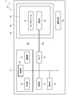
- FIG. 2 is a block diagram showing the configuration of the blood pressure measurement device.
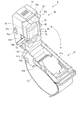
- FIG. 3 is a perspective view showing a configuration of a sensor device of the blood pressure measurement device.
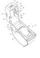
- FIG. 4 is a perspective view showing a configuration of a part of the sensor device of the blood pressure measurement device.
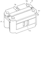
- FIG. 5 is a perspective view showing a configuration of a sensor unit of the blood pressure measurement device.
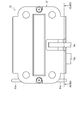
- FIG. 6 is a plan view showing the configuration of the sensor unit.
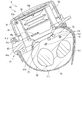
- FIG. 7 is a cross-sectional view showing a configuration in which the sensor module and the air bag of the sensor unit are cut along the VII-VII line cross section shown in FIG. FIG.
- FIG. 8 is a cross-sectional view showing a configuration in which the sensor module and the air bag of the sensor unit are cut along the section VIII-VIII shown in FIG.
- FIG. 9 is a cross-sectional view showing a configuration of the sensor module and the air bag of the sensor unit cut along the line IX-IX shown in FIG.
- FIG. 10 is a cross-sectional view showing a configuration of the blood pressure measurement device.
- FIG. 11 is a cross-sectional view showing a configuration of the blood pressure measurement device.
- FIG. 12 is a cross-sectional view showing a configuration of the blood pressure measurement device.
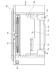
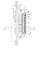
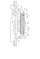
- FIG. 13 is a cross-sectional view showing a configuration of a sensor module of the sensor unit.
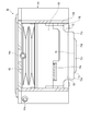
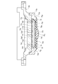
- FIG. 14 is a cross-sectional view showing the configuration of the sensor module.
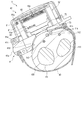
- FIG. 15 is a perspective view showing a sensor base of the sensor module.
- FIG. 16 is a plan view showing a configuration of a sensor module of the sensor unit.
- FIG. 17 is an explanatory diagram showing position adjustment of the sensor unit of the blood pressure measurement device.
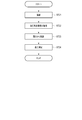
- FIG. 18 is a flowchart showing an example of the manufacturing method of the sensor module.
- FIG. 19 is a flowchart showing an example of blood pressure measurement using the blood pressure measurement device.
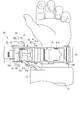
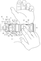
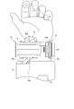
- FIG. 20 is an explanatory diagram showing an example of blood pressure measurement using the blood pressure measurement device.
- FIG. 21 is an explanatory diagram showing an example of blood pressure measurement using the blood pressure measurement device.
- FIG. 22 is an explanatory diagram showing an example of blood pressure measurement using the blood pressure measurement device.
- FIG. 23 is a cross-sectional view showing a configuration of a sensor module of a blood pressure measurement device according to another embodiment of the present invention.
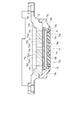
- FIG. 24 is a cross-sectional view showing a configuration of a sensor module of a blood pressure measurement device according to another embodiment of the present invention.
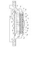
- FIG. 25 is a cross-sectional view showing the configuration of the sensor module.
- FIG. 26 is a cross-sectional view showing a configuration of a sensor module of a blood pressure measurement device according to another embodiment of the present invention.
- FIG. 27 is a cross-sectional view showing a configuration of a sensor module of a blood pressure measurement device according to another embodiment of the present invention.
- FIG. 28 is a cross-sectional view showing a configuration of a sensor module of a blood pressure measurement device according to another embodiment of the present invention.
- FIG. 29 is a cross-sectional view showing a configuration of a sensor module of a blood pressure measurement device according to another embodiment of the present invention.
- FIG. 30 is a cross-sectional view showing a configuration of a sensor module of a blood pressure measurement device according to another embodiment of the present invention.
- FIG. 31 is a cross-sectional view showing a configuration of a sensor module of a blood pressure measurement device according to another embodiment of the present invention.
- FIG. 32 is a perspective view showing a configuration of a blood pressure measurement device according to another embodiment of the present invention.
- FIG. 33 is a block diagram showing a configuration of the blood pressure measurement device.
- FIG. 34 is a perspective view showing a configuration of a blood pressure measurement device according to another embodiment of the present invention.
- FIG. 1 is a perspective view showing a configuration of a blood pressure measurement device 1 according to an embodiment of the present invention with a main body fixture 16 closed.
- FIG. 2 is a block diagram illustrating a configuration of the blood pressure measurement device 1.
- FIG. 3 is a perspective view showing the configuration of the sensor device 5 of the blood pressure measurement device 1 with the sensing body 42 opened.
- FIG. 4 is a perspective view illustrating a configuration in which the sensor unit 52 is removed from the sensor device 5 of the blood pressure measurement device 1.
- FIG. 5 is a perspective view showing the configuration of the sensor unit 52 of the blood pressure measurement device 1.
- FIG. 6 is a plan view showing the configuration of the sensor unit 52.
- FIG. 7 is a cross-sectional view showing the configuration of the sensor module 63 and the air bag 62 of the sensor unit 52 taken along the line VII-VII shown in FIG.
- FIG. 8 is a cross-sectional view showing the configuration of the sensor module 63 and the air bag 62 of the sensor unit 52 taken along the line VIII-VIII shown in FIG.
- FIG. 9 is a cross-sectional view showing the configuration of the sensor module 63 and the air bladder 62 of the sensor unit 52 taken along the line IX-IX.
- FIG. 10 is a cross-sectional view showing the configuration of the blood pressure measurement device 1.
- FIG. 11 is a cross-sectional view showing the configuration of the blood pressure measurement device 1.
- FIG. 12 is a cross-sectional view showing the configuration of the blood pressure measurement device 1.
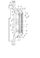
- FIG. 13 is a cross-sectional view showing a state in which the configuration of the sensor module 63 of the sensor unit 52 is cut along a cross section along the direction in which the pressure sensitive elements 71 c of the pressure sensor unit 71 are arranged.
- FIG. 14 is a cross-sectional view showing a state in which the configuration of the sensor module 63 is cut along a cross section along a direction orthogonal to the direction in which the pressure sensitive elements 71c are arranged.
- FIG. 15 is a perspective view showing the sensor base 72 of the sensor module 63.
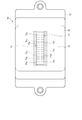
- FIG. 16 is a plan view showing the configuration of the sensor module 63 of the sensor unit 52.
- the radial artery of the wrist 100 is denoted by 110
- the radial bone is denoted by 111
- the ulnar artery is denoted by 112
- the ulna is denoted by 113
- the tendon is denoted by 114.
- the blood pressure measurement device 1 is an electronic blood pressure measurement device that is attached to a wrist 100 of a living body and calculates a blood pressure value from the pressure of the radial artery 110. As shown in FIGS. 1 to 16, the blood pressure measurement device 1 includes a device body 4 and a sensor device 5. For example, in the blood pressure measurement device 1, the sensor device 5 is attached to a region of the wrist 100 where the radial artery 110 exists, and the device body 4 is attached to the wrist 100 adjacent to the elbow side of the sensor device 5.
- Such a blood pressure measurement device 1 measures the pressure pulse wave pressure for each heartbeat that changes in conjunction with the heartbeat of the radial artery 110 by compressing the radial artery 110 with the sensor device 5, and the measured pressure Is processed by the apparatus main body 4 based on the tonometry method to determine the blood pressure.
- the apparatus main body 4 includes a main body case 11, an operation unit 12, a display unit 13, a pump 14, a control board 15, and a main body fixture 16. Further, for example, the apparatus main body 4 may be configured to include a cuff in the main body fixture 16 and press the wrist 100 during blood pressure measurement.
- the main body case 11 accommodates a part of the operation unit 12, a part of the display unit 13, and the control board 15, and exposes a part of the operation unit 12 and a part of the display unit 13 from the outer surface.
- the main body case 11 is attached with a main body fixing tool 16.
- the operation unit 12 is configured to be able to input a command from the user.
- the operation unit 12 includes a plurality of buttons 21 provided on the main body case 11 and a sensor that detects an operation of the buttons 21.
- the operation unit 12 may be a touch panel and may be provided on the display unit 13.
- the operation unit 12 converts a command into an electric signal when operated by a user.
- the sensor that detects the operation of the button 21 is electrically connected to the control board 15 and outputs an electrical signal to the control board 15.
- the display unit 13 is disposed on the main body case 11 so as to be exposed from the outer surface of the main body case 11.
- the display unit 13 is electrically connected to the control board 15.
- the display unit 13 is, for example, a liquid crystal display or an organic electroluminescence display.
- the display unit 13 displays various information including blood pressure values such as date and time, maximum blood pressure, and minimum blood pressure, and measurement results such as heart rate.
- the pump 14 is, for example, a piezoelectric pump.
- the pump 14 has a tube 14a connected to the sensor device 5, compresses air, and supplies the compressed air to the sensor device 5 through the tube 14a.
- the pump 14 is electrically connected to the control board 15.
- the control board 15 includes, for example, a communication unit 31, a storage unit 32, and a control unit 33.
- the control board 15 is configured by mounting the communication unit 31, the storage unit 32, and the control unit 33 on the board.
- the control board 15 is connected to the sensor device 5 via a cable 15a.
- the cable 15 a is disposed outside the main body case 11 through a part of the outer surface of the main body case 11.
- the cable 15 a is arranged in the sensor device 5 from the inside of the main body case 11 through an opening provided on the side surface of the main body case 11.
- the communication unit 31 is configured to be able to transmit and receive information with an external device wirelessly or by wire.
- the communication unit 31 transmits, for example, information controlled by the control unit 33 and information such as measured blood pressure value and pulse to an external device via a network, and software from the external device via the network.
- An update program is received and sent to the control unit.
- the network is, for example, the Internet, but is not limited thereto, and may be a network such as a LAN (Local Area Network) provided in a hospital, or a predetermined standard such as USB. It may be a direct wired communication with an external device using a cable having a terminal. Therefore, the communication unit 31 may include a plurality of wireless antennas and micro USB connectors.
- LAN Local Area Network
- USB Universal Serial Bus
- the storage unit 32 calculates a blood pressure value and a pulse from program data for controlling the entire blood pressure measurement device 1, setting data for setting various functions of the blood pressure measurement device 1, and pressure measured by the pressure-sensitive element 71c.
- the calculation data and the like for this are stored in advance. Further, the storage unit 32 stores information such as the calculated blood pressure value, the pulse, and time series data in which these calculated data are associated with time.
- the control unit 33 is configured by, for example, a single or a plurality of CPUs (Central Processing Unit), and controls the operation of the entire blood pressure measurement device 1 and performs each process based on the program data.
- the control unit 33 is electrically connected to the operation unit 12, the display unit 13, the pump 14, and the sensor device 5, and controls the operation of each component, transmits / receives signals, or supplies power.
- the main body fixing tool 16 includes, for example, one or a plurality of band-shaped bands and a fixing member such as a hook-and-loop fastener that wraps the band around the wrist 100 and fixes the main body case 11 to the wrist 100.
- a fixing member such as a hook-and-loop fastener that wraps the band around the wrist 100 and fixes the main body case 11 to the wrist 100.
- blood pressure data is continuously generated from the pulse wave of the radial artery 110 detected by the sensor device 5 by the control unit 33 performing processing using the program data stored in the storage unit 32.
- the blood pressure data includes blood pressure waveform data corresponding to the measured pulse wave waveform.
- the blood pressure data may further include time-series data of blood pressure feature amounts (blood pressure values). Examples of the blood pressure feature amount include, but are not limited to, systolic blood pressure (SBP) and diastolic blood pressure (DBP; Diastolic Blood Blood Pressure).
- SBP systolic blood pressure
- DBP diastolic blood pressure
- the maximum value in the pulse waveform for one heartbeat corresponds to systolic blood pressure
- the minimum value in the pulse waveform for one heartbeat corresponds to diastolic blood pressure.
- the apparatus main body 4 measures a pressure pulse wave as a pulse wave by a tonometry method.
- the tonometry method is a method in which the radial artery 110 is pressed from above the skin with an appropriate pressure to form a flat portion in the artery, and the sensor device 5 performs pressure in a state where the inside and outside of the radial artery 110 are balanced.
- a method for measuring pulse waves According to the tonometry method, blood pressure values for each heartbeat can be obtained.
- the sensor device 5 includes an attach part 41, a sensing body 42, and a fixture 43.
- the attachment part 41 has a shape in which one main surface follows the circumferential direction of the wrist 100 in the region where the radial artery 110 of the wrist 100 of the left hand exists.
- the attachment part 41 is provided on the base 41a, an opening 41b formed in the base 41a, and a base 41a in which a region in contact with the wrist 100 is curved following the shape of the wrist 100 in the circumferential direction.
- a cushion 41d provided on the main surface of the base 41a that comes into contact with the wrist 100 of the base 41a.
- the base 41a is configured to be long in one direction.
- the base 41a is disposed on the palm side of the wrist 100 and on the side of the wrist 100 on the side of the rib 111, and in the circumferential shape of the palm of the wrist 100 and the side of the wrist 100 on the side of the rib 111.
- the main surface arranged on the wrist 100 side is curved.
- the base 41 a abuts at least the main surface on the outer peripheral edge side with the sensing body 42.
- the opening 41b is provided on the center side of the base 41a, and is formed in a size that allows one or more fingers to be arranged. That is, the opening 41b can palpate a region where the radial artery 110 of the wrist 100 exposed from the opening 41b exists with a finger when the sensor device 5 is attached to the wrist 100, and a part of the sensing body 42 is It is formed in a size that can contact the wrist 100.
- the mounting portion 41c is a main surface opposite to the surface facing the wrist 100 of the base portion 41a, and is provided on one end side in the longitudinal direction of the base portion 41a.
- the attachment portion 41c is configured to hold the sensing body 42 and to move the sensing body 42 in a direction away from the base portion 41a and a direction approaching the base portion 41a.
- the attachment portion 41c is a shaft support portion that supports the sensing body 42 so as to be rotatable about one axis.
- the attachment portion 41c is formed integrally with the base portion 41a.
- the cushion 41d is, for example, an elastic body configured in a sheet shape with a foamable resin material provided on a main surface that comes into contact with the wrist 100 of the base 41a.
- the cushion 41d protects the wrist 100 by elastically deforming, for example, when the blood pressure measurement device 1 is attached to the wrist 100.
- the sensing main body 42 includes a case 51, a sensor unit 52, and an adjusting unit 53 that adjusts the position of the sensor unit 52.
- the case 51 is configured, for example, in a rectangular box shape with a surface facing the attachment part 41 being opened.
- the case 51 holds the sensor unit 52 and the adjusting means 53.
- the case 51 is attached to the attachment portion 41c so as to be able to reciprocate in a direction away from the base portion 41a.
- the case 51 includes a rotation shaft 51a that is rotatably provided on the attachment portion 41c.
- the case 51 has an engagement portion 51b that fixes the case 51 to the base portion 41a when it contacts the base portion 41a.
- the engaging portion 51b is, for example, a protrusion that engages with an opening provided in the base portion 41a, and is configured to be disengaged from the opening of the base portion 41a when operated.
- the case 51 includes a first hole 51c in which the tube 14a is disposed, a second hole 51d in which the cable 15a is disposed, a third hole 51e that movably supports a part of the adjusting means 53, and a sensor.
- the first hole 51c and the second hole 51d are provided on the same side wall of the case 51 adjacent to the apparatus body 4 when the first hole 51c and the second hole 51d are attached to the wrist 100.
- 3rd hole 51e is provided in the side wall opposite to the side wall of case 51 in which the 1st hole 51c and the 2nd hole 51d are provided.
- the third hole 51 e is a rectangular opening that extends linearly in the longitudinal direction of the case 51, in other words, when the sensor device 5 is attached to the wrist 100.
- the guide groove 51f is provided on the inner surface side of the side wall of the case 51 in which the third hole 51e is provided.
- the guide groove 51f includes a first groove 51f1 extending from the opening end of the case 51 to a midway toward the top wall facing the opening, and a first groove 51f extending in a direction orthogonal to the first groove 51f1. 2 grooves 51f2.
- One end of the second groove 51 f 2 is continuous with the first groove 51 f 1, and one end to the other end extends toward one side in the longitudinal direction of the case 51.
- the sensor unit 52 includes a movable case 61, an air bag 62, a sensor module 63, and a movable base 64 that holds the sensor module 63 movably in one direction with respect to the movable case 61.
- the sensor unit 52 is held by the case 51 so as to be movable within a predetermined range along the longitudinal direction of the case 51 by the adjusting means 53.
- the movable case 61 accommodates the sensor module 63 and the movable base 64, and holds the movable base 64 holding the sensor module 63 movably toward the opening 41b of the attach portion 41.
- the movable case 61 is held in the case 51 so as to be movable along the longitudinal direction of the case 51.
- the movable case 61 is configured in a rectangular box shape in which a surface facing the attachment portion 41 that houses the air bag 62 and the sensor module 63 is opened.
- the movable case 61 accommodates the air bag 62, the sensor module 63, and the movable base 64.
- the movable case 61 has an air bag 62 disposed between the top wall and the movable base 64.
- the movable case 61 holds the movable base 64 movably in one direction so that the sensor module 63 can protrude and retract from the opening of the movable case 61.
- the movable case 61 has a guide protrusion 61a that is arranged so that the guide groove 51f can be moved on the outer surface of the side wall of the case 51 that faces the side wall where the guide groove 51f is provided, and a fixed portion to which a part of the adjusting means 53 is fixed. 61b. As the guide protrusion 61 a moves along the second groove 51 f 2, the movable case 61 moves along the longitudinal direction of the case 51.
- the air bag 62 has a bellows structure.
- the air bladder 62 is fluidly connected to the pump 14 via the tube 14a. As shown in FIGS. 7 to 12, the air bag 62 expands in a direction from the top wall of the movable case 61 toward the opening.
- the air bag 62 is inflated so that the sensor module 63 protrudes from the opening of the movable case 61 from the position where the sensor module 63 is accommodated in the movable case 61 and touches the wrist 100 from the opening 41b of the attachment part 41. Until the sensor module 63 is moved.
- the air bag 62 is formed of polyurethane, for example.
- the sensor module 63 includes a pressure sensor unit 71, a sensor base 72 that holds the pressure sensor unit 71, a sensor head cover 73 that covers the sensor base 72, and a soft unit 74. It is equipped with.
- the sensor module 63 is disposed in the movable case 61 and is held by the movable case 61 so as to be movable within a predetermined movement range along the direction in which the top wall of the movable case 61 and the opening are opposed. That is, the sensor module 63 is held movably in the movable case 61 and its movement is restricted by a restriction means such as a stopper when the sensor module 63 is moved to a position protruding beyond a certain amount from the opening of the movable case 61.
- the pressure sensor unit 71 includes a flexible substrate 71a, a substrate 71b mounted on the flexible substrate 71a, and a plurality of pressure sensitive elements 71c mounted on the substrate 71b.
- the pressure sensor unit 71 is fixed on one main surface of the sensor base 72.
- the flexible substrate 71a is bonded and fixed on the sensor base 72 via an adhesive sheet 71f, for example.
- a predetermined circuit pattern is formed on one main surface of the flexible substrate 71a.
- a substrate 71b is mounted on the flexible substrate 71a.
- a cable 15a is connected to the circuit pattern of the flexible substrate 71a.
- the cable 15a is composed of, for example, a flexible substrate. That is, the flexible board 71a is electrically connected to the control board 15 via the cable 15a.
- the substrate 71b is electrically connected to the flexible substrate 71a.
- the board 71b is electrically connected to the control board 15 via the flexible board 71a and the cable 15a.
- the substrate 71b is configured as a rectangular plate.
- the plurality of pressure sensitive elements 71c are mounted on the substrate 71b.
- the plurality of pressure sensitive elements 71c are electrically connected to the circuit pattern on the flexible substrate 71a. That is, the plurality of pressure sensitive elements 71c are electrically connected to the control board 15 via the board 71b, the flexible board 71a, and the cable 15a.
- the substrate 71b and the plurality of pressure sensitive elements 71c constitute a sensor chip.
- a plurality of pressure sensitive elements 71c are arranged in one direction to constitute a pressure sensitive element row 71d.
- One or a plurality of pressure-sensitive element rows 71d are provided.
- the plurality of pressure-sensitive element rows 71d are arranged at predetermined intervals in a direction orthogonal to the arrangement direction of the plurality of pressure-sensitive element rows 71d.
- the pressure sensitive element rows 71d are formed in two rows as an example in the present embodiment.
- the pressure sensor unit 71 is disposed on the sensor base 72 so that one direction in which the plurality of pressure sensitive elements 71 c are disposed is the width direction of the wrist 100.
- the pressure sensor unit 71 transmits the pressure value measured by the number of pressure sensitive elements 71c to the control board 15 via the cable 15a.
- the sensor base 72 is made of, for example, a synthetic resin.
- the sensor base 72 integrally includes a support wall portion 72a and a peripheral wall portion 72b erected from the outer peripheral edge of the support wall portion 72a on the back side opposite to the living body.
- the sensor base 72 holds the pressure sensor unit 71 and the cable 15 a connected to the pressure sensor unit 71.
- the support wall 72a is formed in a rectangular plate shape having a predetermined thickness.
- the wrist 100 side of the support wall portion 72a is defined as the surface side.
- the support wall portion 72a holds the pressure sensor portion 71 on the main surface 72a1 on the front surface side.
- a groove 76 is formed on the outer peripheral edge of the main surface 72a1 on the wrist 100 side of the support wall 72a so that the support wall 72a is convex on the wrist 100 side.
- the groove portion 76 is configured such that the sensor head cover 73 can be fitted therein.
- a pressure sensor unit 71 is fixed to the main surface 72a1 via an adhesive sheet 71f.
- a plurality of holes (flow holes) 72d are formed in the support wall 72a, for example.
- the plurality of holes 72d penetrate the support wall 72a in the thickness direction, and open to the main surface 72a1 and the other main surface 72a2.
- the plurality of holes 72d are formed so that the material forming the soft portion 74 can flow.
- the hole 72d communicates with a gap 79 described later. For example, four holes 72d are formed.
- the pressure sensor portion 71 is fixed to the main surface 72a1 of the support wall portion 72a, and a part of the pressure sensor portion 71 faces the hole 72d.
- a communicating portion 71g communicating with the hole 72d and the gap 79 is formed at a position facing the hole 72d in the pressure sensor portion 71.
- the communication part 71g is, for example, a hole.
- the communication portion 71g has a hole 71f1 formed in the adhesive sheet 71f and a hole 71a3 formed in the flexible substrate 71a.
- the communication portion 71g is not limited to a hole. For example, it may be a notch.
- the hole 72d may be opened at a position on the main surface 72a1 away from the pressure sensor unit 71.
- the communication part 71g is not formed.
- the communication of the hole 72d with the gap portion 79 includes communication through the communication portion 71g and direct communication.
- the peripheral wall portion 72b is erected from the outer periphery of the support wall portion 72a on the side opposite to the living body.
- the peripheral wall portion 72 b is fixed to the movable base 64.
- the sensor head cover 73 is in contact with the wrist 100 at the end surface on the wrist 100 side and a part of the peripheral surface intersecting the end surface.
- the sensor head cover 73 is made of, for example, a synthetic resin material.
- the sensor head cover 73 integrally includes a convex portion 73b and a frame portion 73c erected on the sensor base 72 side from the periphery of the convex portion 73b. At least a part of the opposing surfaces of the sensor head cover 73 and the sensor base 72 are separated from each other, and a gap 79 is formed between the inner surface 73 g of the sensor head cover 73, the sensor base 72, and the pressure sensor portion 71.
- the convex portion 73b is configured in a rectangular plate shape, for example.
- An end surface (planar portion) 73d which is the main surface of the convex portion 73b on the living body side, is formed in a plane.
- the convex portion 73b has an end surface 73d and a peripheral surface 73e continuous to the end surface 73d.
- the peripheral surface 73e is along the thickness direction of the convex part 73b.
- the end surface 73d and a part of the peripheral surface 73e are regions that contact the wrist 100 on the outer surface of the sensor module 63 when the blood pressure measurement device 1 is used.
- the fitting part 73f which fits into the groove part 76 of the sensor base 72 is provided in the end by the side of the sensor base 72 of the frame part 73c.
- the inner surface 73g of the sensor head cover 73 is constituted by the inner surface of the convex portion 73b on the pressure sensor portion 71 side and the inner surface of the frame portion 73c.
- the inner surface 73 g has a gap 79 between the pressure sensor 71 and the sensor base 72. The gap 79 communicates with the plurality of holes 72d.
- the sensor head cover 73 configured in this manner is formed of a rubber member in a region that contacts the wrist 100 when the blood pressure measurement device 1 is used.
- a portion of the convex portion 73b on the wrist 100 side is rubber.
- the rubber portion 75 is made of a material.
- a part of the convex portion 73b on the wrist 100 side that forms the outer surface in contact with the wrist 100 is configured as a rubber portion 75 formed of a rubber member.
- the rubber part 75 has an end surface 73d that contacts the wrist 100 and a part of the peripheral surface 73e.
- a part of the inner surface 73g is constituted by a rubber portion 75.
- the inner surface 75 a on the pressure sensor portion 71 side of the rubber portion 75 has an area and a shape facing all the pressure sensitive elements 71 c of the pressure sensor portion 71 in the thickness direction of the rubber portion 75.
- the rubber part 75 is formed of a rubber material capable of transmitting the pressure from the wrist 100 to the pressure sensor part 71 side.
- An example of the rubber material is a rubber material having a frequency characteristic of 100 Hz to 200 Hz.
- the rubber portion 75 is formed using silicone rubber as a rubber material that satisfies these conditions.
- the portions other than the rubber portion 75 of the sensor head cover 73 are made of, for example, resin.
- the rubber part 75 is formed integrally with a part other than the rubber part 75.
- the rubber part 75 should just be formed with the material which can detect the pressure of the radial artery 110 by the pressure sensor part 71, and the material of the rubber part 75 can be set suitably.
- the soft part 74 is provided in the gap part 79.
- the soft part 74 is provided at least between the rubber part 75 in the gap part 79 and the pressure sensitive element 71c of the pressure sensor part 71, and is configured to be able to transmit the pressure from the rubber part 75 to the pressure sensitive element 71c.
- the soft part 74 is configured to be able to transmit the pressure of the radial artery 110 transmitted from the rubber part 75 to the pressure sensitive element 71c.
- the soft part 74 is filled in the range from the pressure sensor part 71 side surface of the rubber part 75 to the adhesive sheet 71f as an example. Note that a part of the sensor head cover 73 is in contact with the adhesive sheet 71f as shown in FIG. 13, and the other part is not in contact with the adhesive sheet 71f as shown in FIG. For this reason, a part of the soft part 74 is located at a position beyond the adhesive sheet 71f as shown in FIG.
- the flexible portion 74 is filled in the range from the pressure sensor portion 71 side surface of the rubber portion 75 to the adhesive sheet 71f, so that the flexible substrate 71a, the substrate 71b, and all the pressure sensitive elements 71c of the pressure sensor portion 71 are formed.
- the soft portion 74 is in close contact with the area of the inner surface 73g that is covered with the soft portion 74 and faces the pressure sensor portion 71.
- the soft portion 74 is formed by injecting a relatively soft resin material such as silicone resin into the gap 79 from the main surface 72a2 side through the hole 72d.
- the hardness of the soft part 74 is lower than the hardness of the rubber part 75. In other words, the hardness of the rubber part 75 is higher than the hardness of the soft part 74.
- the soft part 74 only needs to be formed of a material that can detect the pressure of the radial artery 110 by the pressure sensor part 71, and the thickness of the soft part 74 and the shape and material in contact with the wrist 100 can be set as appropriate. .
- the adjusting means 53 is configured to be able to adjust the position of the sensor unit 52 with respect to the case 51 in the circumferential direction of the wrist 100 as shown in FIG.
- the adjustment means 53 has an adjustment knob 53a that is located on the outer surface of the case 51 and that is partly fixed to the fixed portion 61b of the movable case 61 via the third hole 51e.
- the adjustment means 53 includes a scale 53b provided adjacent to the third hole 51e of the case 51, and an instruction part 53c provided on the adjustment knob 53a and pointing to the scale 53b.
- the adjustment knob 53 a is connected to the sensor unit 52 by being fixed to the movable case 61.
- the adjustment knob 53a is configured to be able to move the sensor unit 52. That is, the adjustment means 53 moves the sensor unit 52 along the second groove 51f2 by moving the adjustment knob 53a in the longitudinal direction of the third hole 51e, and adjusts the position with respect to the case 51. It is an adjustment mechanism.
- the scale 53b and the instruction unit 53c are display units that display the position of the adjustment knob 53a, that is, the position of the sensor unit 52 connected to the adjustment knob 53a in a visible manner.
- the fixing tool 43 includes, for example, one or a plurality of band-shaped bands and a fixing member such as a hook-and-loop fastener that wraps the band around the wrist 100 and fixes the attachment part 41 and the sensing body 42 to the wrist 100.
- the fixing tool 43 may be comprised by the 1st belt called the parent which has a buckle, and the 2nd belt called the sword tip fixed to a buckle.
- the fixing tool 43 may further have a configuration for fixing the case 51 to the attachment portion 41 by being wound around the case 51.
- the repulsive force when the sensor module 63 presses the wrist 100 due to the expansion of the air bag 62 is applied to the movable case 61, and the adjustment knob 53a directly or from the movable case 61 by the movable case 61. It may be possible to prevent the case 51 from being indirectly pressed via the movement of the case 51 in a direction away from the attachment portion 41.
- FIG. 18 is a flowchart illustrating an example of a method for manufacturing the sensor module 63.
- the manufacturing method of the sensor module 63 includes a sensor setting process (step ST11) for setting the pressure sensor unit 71 on the sensor base 72, a cover assembly process (step ST12) for mounting the sensor head cover 73 to the sensor base 72, and a soft And a filling step (step ST13) for supplying a material for forming the portion 74.
- a plurality of pressure sensitive elements 71c are mounted on the substrate 71b.
- the substrate 71b on which the plurality of pressure sensitive elements 71c are mounted is mounted on the flexible substrate 71a. Thereby, the pressure sensor unit 71 is completed.
- the pressure sensor unit 71 is fixed on the sensor base 72 via the adhesive sheet 71f.
- the sensor head cover 73 is placed on the sensor base 72 as a cover assembling step (step ST12). At this time, a gap 79 is formed between the sensor base 72 and the sensor head cover 73.
- a filling process (step ST13) is performed.
- a filling step first, in a state where the sensor base 72 and the sensor head cover 73 are assembled, the integrated body is brought into a posture in which the convex portion 73b is downward in the direction of gravity.
- the nozzle 82 that flows out the soft resin is inserted into the hole 72d from the main surface 72a2 side, and a predetermined amount of the material of the soft portion 74 is supplied from the hole 72d.
- the material flows into the gap 79 from the hole 72d by its own weight, for example, and fills a part of the gap 79.
- this part is the range from the surface by the side of the pressure sensor part 71 of the convex part 73b to the adhesive sheet 71f as above-mentioned.
- the material of the soft part 74 supplied to the gap part 79 forms the soft part 74.
- the soft portion 74 may be formed by performing a cooling treatment or a heat treatment according to the type of material of the soft portion 74.
- the sensor module 63 is completed.
- FIG. 19 is a flowchart showing an example of blood pressure measurement using the blood pressure measurement device 1, and shows both the user's operation and the operation of the control unit 33.
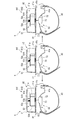
- 20 to 22 are explanatory diagrams illustrating an example of blood pressure measurement using the blood pressure measurement device 1.
- the user searches for the position of the radial artery 110 on the wrist 100 by palpation (step ST21).
- the skin on the radial artery 110 may be marked by drawing a line with a pen.
- the user moves the sensing body 42 of the sensor device 5 away from the attachment unit 41.
- the user operates the engagement portion 51b to release the fixing of the case 51 and the base portion 41a, and rotates the sensing body 42 around the rotation shaft 51a in a direction away from the attachment portion 41.
- the user wears the apparatus main body 4 and the sensor apparatus 5 (step ST22).
- the user passes the wrist 100 through the body fixture 16 of the device body 4 and the fixture 43 of the sensor device 5, and places the device body 4 and the sensor device 5 at predetermined positions on the wrist 100.
- the main body fixing tool 16 of the apparatus main body 4 is tightened to fix the apparatus main body 4 to the wrist 100.
- the body fixing tool 16 of the apparatus main body 4 is configured to have a cuff, the skin of the wrist 100 is not sandwiched between the body fixing tool 16 (cuff) and the body fixing tool 16 (cuff) is Check for looseness.
- the position of the sensor device 5 is adjusted so that the opening 41 b of the attach portion 41 of the sensor device 5 is located at the radial artery 110 of the wrist 100. Further, the user fixes the sensor device 5 to the wrist 100 by tightening the fixture 43 of the sensor device 5 while maintaining the radial artery 110 positioned in the opening 41b.
- the user palpates the wrist 100 from the opening 41b of the attachment unit 41 (step ST23), and confirms again that the radial artery 110 is located in the opening 41b.
- the user rotates the sensing main body 42 in a direction close to the attachment portion 41 and fixes the sensing main body 42 to the attachment portion 41 by the engaging portion 51 b.
- the position of the sensing body 42 is adjusted by operating the adjustment knob 53a.
- the control unit 33 measures the blood pressure based on the blood pressure measurement command (step ST24). At this time, the control unit 33 drives and controls the pump 14 to inflate the air bag 62, so that the sensor module 63 is gradually housed in the movable case 61 as shown in FIGS.
- the sensor head cover 73 and the soft part 74 of the sensor module 63 press the region where the radial artery 110 of the wrist 100 exists.
- the radial artery 110 is pressed with an appropriate pressure, so that a flat part is formed in the radial artery 110.
- each pressure sensitive element 71c of the pressure sensor unit 71 measures a pressure pulse wave.
- the control unit 33 obtains the blood pressure by the tonometry method from the pressure pulse wave of the radial artery 110 detected by the pressure sensor unit 71. Prior to blood pressure measurement, the control unit 33 may perform blood pressure measurement for calibration based on the program data stored in the storage unit 32, and the mounting state and pressure of the device main body 4 and the sensor device 5 may be measured. You may determine whether the position of the sensor part 71 is correct.
- the sensor head cover 73 has the rubber portion 75 that constitutes a region in contact with the wrist 100 on the outer surface. For this reason, when the blood pressure measurement device 1 is used, the end surface 73d of the rubber part 75 and a part of the peripheral surface 73e along the thickness direction come into contact with the wrist 100, but the rubber part 75 is made of a rubber member. Therefore, the protective strength of the surface of the sensor module 63 that contacts the wrist 100 can be improved, and damage can be prevented. Furthermore, a user's touch can be improved.
- the wrist 100 can be palpated while the sensor device 5 is worn, so whether or not the sensor device 5 is worn at a predetermined position. Can be easily determined. That is, it is possible to palpate the wrist 100 from the opening 41b, and when the sensor device 5 of the blood pressure measurement device 1 is attached to the wrist 100, the radial artery 110 is temporarily attached to the wrist 100 while the sensor device 5 is temporarily attached to the wrist 100. By searching through palpation, the position of the sensor device 5 can be adjusted, and then it can be fully mounted. As a result, it is easy to attach the blood pressure measurement device 1 to an appropriate position.
- the radial artery 110 can be further operated by operating the adjusting knob 53a. Since the position of the sensor unit 52 can be adjusted with respect to the radial artery 110, the pressure of the radial artery 110 can be measured at a suitable position.
- the sensor device 5 is configured such that the sensing body 42 rotates relative to the attachment unit 41 around one axis as a configuration in which the sensing body 42 can move in a direction away from the attachment unit 41. For this reason, when the sensing main body 42 is moved, the sensor module 63 provided in the sensing main body 42 moves in a direction away from the opening 41 b of the attach portion 41.
- the sensor module 63 can be prevented from moving while being in contact with the wrist 100 or the attachment unit 41. More specifically, the sensor unit 52 measures the blood pressure in a state where the sensor head cover 73 and the soft part 74 of the sensor module 63 protrude from the opening of the movable case 61 to a position where the wrist 100 can be appropriately pressed by the air bag 62. Is done.
- the sensing body 42 moves relative to the attachment unit 41 in such a state, the sensing body 42 moves in a direction in which the sensor module 63 is separated from the wrist 100, so that the end surface of the sensor head cover 73 and the soft part 74 are The sensing body 42 does not move while in contact with the wrist 100 or the attachment unit 41. For this reason, when the sensing body 42 is moved, the sensor module 63 can be prevented from being damaged due to interference with other configurations or the wrist 100, and a burden on the wrist 100 can be prevented.
- the sensor device 5 is provided with the opening 41b having a palpable shape in the attach portion 41 and enables the sensing main body 42 to move in a direction away from the attach portion 41 and the wrist 100, whereby the sensor module 63 is provided. Can be prevented, and safety can be improved.
- the attachment portion 41 is provided with the attachment portion 41, and the rotation shaft 51a pivotally supported by the attachment portion 41c is provided.
- a simple configuration provided in the sensing body 42 may be used. For this reason, compared with the structure etc. which are slid to one direction with respect to the attachment part 41, the sensor apparatus 5 becomes a simple structure, and can be manufactured cheaply.
- the sensor device 5 has a configuration in which the sensing body 42 rotates with respect to the attachment portion 41 on one end side in the longitudinal direction of the attachment portion 41, so that substantially the entire area of the upper surface of the attachment portion 41 is exposed to the outside. be able to. For this reason, since all the opening parts 41b of the attachment part 41 are exposed, the shape of the opening part 41b required in order to perform palpation can be made as small as possible. In addition, since the rail structure for sliding the sensing body 42 with respect to the attachment part 41 and the structure for holding the sensing body 42 on the attachment part 41 after the sliding movement are not required, the sensor device 5 is provided in the width direction of the wrist 100. Since the shape of can be made as small as possible, the size can be reduced.
- the sensor head cover 73 includes the rubber portion 75 that constitutes a region in contact with the wrist 100 on the outer surface.
- the protective strength of the surface in contact with the surface can be improved and damage can be prevented.
- the rubber portion 75 constitutes the inner surface 75a of the sensor head cover 73 on the pressure sensor portion 71 side, and the inner surface 75a of the rubber portion 75 on the pressure sensor portion 71 side.
- a first convex portion 77a that protrudes toward the pressure sensor portion 71 may be formed in at least a part of the region facing the plurality of pressure sensitive elements 71c.
- the region of the inner surface 75 a facing the plurality of pressure sensitive elements 71 c is a region facing the rubber portion 75 in the thickness direction.
- the first convex portion 77a is formed at a position facing the center of the end surface 73d of the inner surface 75a as an example.
- the first protrusion 77a protrudes to the extent that it does not contact the pressure sensitive element 71c. Since the hard portion compared to the soft portion 74 is positioned closer to the pressure sensitive element 71c by the first convex portion 77a, the pressure of the radial artery 110 is efficiently transmitted to the pressure sensitive element 71c.
- the first convex portion 77a is along the longitudinal direction of the pressure-sensitive element row 71d. Further, it may have a tapered shape in which the cross-sectional area gradually decreases toward the pressure-sensitive element array 71d side.
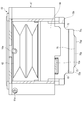
- FIG. 24 shows a state where the sensor module 63 is cut along a cross section along the longitudinal direction of the pressure-sensitive element row 71d.
- 25 is a cross-sectional view taken along the line Fk ⁇ -Fk ⁇ shown in FIG. 24, and shows a state where the sensor module 63 is cut along a cross section orthogonal to the longitudinal direction of the pressure-sensitive element row 71d.
- the first convex portion 77a is configured to extend from a position facing one end in the longitudinal direction of the pressure-sensitive element row 71d to a position facing the other end. Is done.
- the first convex portion 77a is configured to have a triangular cross section as an example of a tapered shape whose cross section decreases toward the pressure-sensitive element array 71d.
- two pressure-sensitive element rows 71d are provided.
- the first convex portion 77a is directed toward the center of the plurality of pressure sensitive element rows 71d in the direction in which the plurality of pressure sensitive element rows 71d are arranged. Constructed in a tapered shape.
- the two pressure-sensitive element rows 71d are configured in a tapered shape between the two pressure-sensitive element rows 71d.
- the pressure-sensitive element rows 71d are tapered toward one pressure-sensitive element row 71d arranged in the middle.
- the first convex portion 77a is configured to taper toward the one pressure-sensitive element row 71d.
- both side surfaces 77a1 of the first convex portion 77a are configured in a plane inclined with respect to the protruding direction of the first convex portion 77a.
- the first convex portion 77a has a trapezoidal or semicircular cross section along the direction toward the pressure sensitive element row 71d as another example of a tapered shape whose cross section decreases toward the pressure sensitive element row 71d. It may be configured in a shape.
- the first convex portion 77a is formed in a shape that is long in the longitudinal direction of the pressure-sensitive element row 71d, that is, in the direction in which the plurality of pressure-sensitive elements 71c are arranged. Since the cross-sectional shape is configured to gradually decrease toward the center in the direction in which the pressure-sensitive element rows 71d are arranged, the pressure from the wrist 100 can be efficiently transmitted to the pressure-sensitive element row 71d.
- the first convex portion 77a shown in FIGS. 24 and 25 has a tapered area in which the cross-sectional area gradually decreases toward the center in the direction in which the plurality of pressure sensitive element rows 71d are arranged.
- the shape is a shape that extends in the direction in which the plurality of pressure sensitive elements 71c are arranged.
- the end surface 73d may be formed with a second convex portion 77b that protrudes toward the wrist 100. Since the 2nd convex part 77b contacts the wrist 100, it is formed in the smooth surface.
- the second convex portion 77b is formed in a dome shape and is located at the center of the end surface 73d.
- the shape of the second convex portion 77b is not limited to the dome shape. In another example, it may be hemispherical, for example.
- the 2nd convex part 77b is not limited to being located in the center of the end surface 73d.
- the 2nd convex part 77b should just be formed in at least 1 part of the area
- the region facing the plurality of pressure sensitive elements 71 c of the pressure sensor portion 71 on the end surface 73 d is a region facing the rubber portion 75 in the thickness direction.
- the structure which the rubber part 75 has the 1st convex part 77a and the 2nd convex part 77b was shown, it is not limited to this.
- the first convex portion 77a may be omitted, and the second convex portion 77b may be included.
- the entire sensor head cover 73 may be formed of the same material as the rubber portion 75.
- the sensor head cover 73 is formed of the same material as the rubber part 75, at least one of the first convex part 77a and the second convex part 77b as shown in FIGS. May be formed.
- an opening 73a is provided in a region of the rubber portion 75 that contacts the wrist 100, and the opening 73a is blocked by the first portion 78a and the second portion 78b. It may be configured.
- the opening 73 a is formed in a region facing all the pressure sensitive elements 71 c of the pressure sensor unit 71.
- the region facing all the pressure sensitive elements 71 c is a region facing the rubber portion 75 in the thickness direction.
- the first portion 78a is located in the opening 73a and is made of the same material as the rubber portion 75.
- the first portion 78a is configured in a disk shape, for example.
- the second portion 78b is located between the first portion 78a and the inner peripheral surface of the opening 73a, and is configured in an annular shape that closes between the first portion 78a and the inner peripheral surface of the opening 73a.
- the second portion 78 b is formed from the same material as the soft portion 74.
- the second portion 78b may be formed integrally with the soft portion 74.
- the smooth surface of the opposing plate 81 with the first portion 78a disposed in the opening 73a. 81a is brought into contact with the end surface 73d to close the opening 73a.
- the counter plate 81 is indicated by a two-dot chain line.
- the material of the soft portion 74 is injected into the hole 72 d by the nozzle 82.
- the soft portion 74 and the second portion 78b are formed by the injected material.
- the first portion 78a is bonded to the soft portion 74 and the second portion 78b, whereby the first portion 78a is fixed in the opening 73a.
- the second portion 78b may be a separate member from the soft portion 74.
- the second portion 78b is formed by providing the second portion 78b formed in an annular shape in the opening 73a.
- the periphery of the first portion 78a constituting the central portion of the opening 73a of the rubber portion 75 is surrounded by the second portion 78b formed of the same material as that of the soft portion 74. According to this configuration, the first portion 78a is easily moved to the pressure sensor portion 71 side by being supported by the second portion 78b having a lower hardness than the first portion 78a. For this reason, the pressure change of the wrist 100 is more easily transmitted to the pressure sensor unit 71.
- the opening 73a is formed in the sensor head cover 73 and the first portion 78a and the second portion 78b are disposed in the opening 73a
- You may have the 1st convex part 77a and the 2nd convex part 77b in the part 78a.
- the first convex portion 77a extends in the arrangement direction of the plurality of pressure sensitive elements 71c, that is, in the longitudinal direction of the pressure sensitive element row 71d, and has a cross-sectional area toward the pressure sensitive element row 71d.
- the shape may gradually decrease.
- it is not limited to having both the 1st convex part 77a and the 2nd convex part 77b, The structure which has only any one may be sufficient.
- the first portion 78a may not be provided, and the opening 73a may be blocked by the second portion 78b.
- the second portion 78b may be formed integrally with the soft portion 74 by the material of the soft portion 74 injected from the hole 72d.
- the end surface on the wrist 100 side of the second portion 78b that is, the end surface 73d of the sensor head cover 73 may be flat, or the second portion 78b as in the modification shown in FIG.
- a convex portion 78b1 protruding toward the wrist 100 may be formed on the end surface of the wrist 100 on the side of 78b.
- the convex portion 78b1 can be formed by forming a recess corresponding to the convex portion 78b1 on the smooth surface 81a of the counter plate 81 shown in FIG. 15, for example.
- the sensor head cover 73 is formed by the rubber portion 75, and the remaining portion is formed by a resin material.
- the sensor head cover 73 is made of a material different from that of the rubber portion 75 and has an opening 73m in a region facing the pressure sensor portion 71.
- the rubber portion 75 may be configured by fixing a member different from the sensor head cover 73.
- the rubber part 75 is provided in a region facing the wrist 100 so that the sensor head cover 73 does not contact the wrist when the blood pressure measurement device 1 is used. Even in this embodiment, since the rubber portion 75 contacts the wrist 100, the protection strength of the surface of the sensor module 63 that contacts the wrist 100 can be improved, and damage can be prevented.
- a sensor head cover 73 formed of resin that has been conventionally used can be used. That is, it is only necessary to fix the rubber part 75 to the sensor head cover 73.
- the rubber part 75 has an opening 73 a that communicates with the opening 73 m of the sensor head cover 73.
- the openings 73m and 73a are closed by the soft portion 74.
- a part of the end surface 73 d is configured by the soft portion 74.
- the rubber part 75 may have a configuration without the opening 73a as a further modification. That is, the rubber part 75 may be configured to close the opening 73m.
- the blood pressure measurement device 1 has been described as having a configuration in which the device main body 4 and the sensor device 5 are provided separately, but is not limited thereto.
- the blood pressure measurement device 1 may be configured such that the device body 4 and the sensor device 5 are integrated.
- the blood pressure measurement device 1 having such a configuration may be configured such that the operation unit 12, the display unit 13, the pump 14, and the control board 15 used in the device body 4 are provided in the case 51 of the sensing body 42.
- the blood pressure measurement device 1 is configured to move in the direction in which the sensing body 42 moves away from and the direction in which the sensing body 42 moves toward the attachment unit 41, and the sensing body 42 rotates with respect to the attachment unit 41 around one axis.
- the present invention is not limited to this.
- the blood pressure measurement device 1 has a configuration in which the attachment unit 41 and the sensing body 42 are separated from each other as a configuration in which the sensing body 42 moves in a direction away from and in a direction in which the sensing body 42 moves toward the attachment unit 41. Also good.
- the engagement portions 51b are provided at a plurality of locations of the case 51 of the sensing body 42, and the sensing body 42 is engaged with the attachment portion 41 at a plurality of positions. do it.
- the blood pressure measurement device 1 measures the pressure of the radial artery 110 and obtains the blood pressure by the tonometry method.
- the configuration is not limited to this, and for example, the pressure measurement device 1 measures the pressure of the ulnar artery 112. It may be.
- requires blood pressure by methods other than the tonometry method may be sufficient as the blood pressure measuring device 1.
- the blood pressure measurement device 1 can move the sensor module 63 in contact with the wrist 100 with respect to the opening 41b of the attachment unit 41 and the wrist 100, and is in contact with the wrist 100 with other configurations. If it is the structure which moves, it can use for the structure which uses another blood-pressure measuring method.
- the opening part 41b of the attachment part 41 was comprised so that palpation was possible, it is not limited to this.
- the opening 41b may be an opening that cannot be palpated.
- sensor unit 53 ... adjusting means 53b ... scale 53c ... indicator 61 ... movable case 61a ... guide protrusion 61b ... Fixed part 62 ... Air bag 63 ... Sensor module 71 ... Pressure sensor part 71a ... Flexible substrate 71b ... Substrate 71c ... Pressure sensitive element 71d ... Pressure sensitive element array 72 ... Sensor base 72a ... support wall portion 73 ... sensor head cover 73a ... opening 73b ... convex portion 73c ... frame portion 73d ... end surface 73e ... circumferential surface 73g ... inner surface 74 ... soft portion 75 ... rubber portion 76 ... groove portion 78a ... first portion 78b ... Second part 79 ... gap part 100 ... wrist 110 ... radial artery 111 ... radius 112 ... ulnar artery 113 ... ulna 114 ... tendon.
Landscapes
- Health & Medical Sciences (AREA)
- Life Sciences & Earth Sciences (AREA)
- Cardiology (AREA)
- Surgery (AREA)
- General Health & Medical Sciences (AREA)
- Engineering & Computer Science (AREA)
- Biomedical Technology (AREA)
- Heart & Thoracic Surgery (AREA)
- Medical Informatics (AREA)
- Molecular Biology (AREA)
- Physics & Mathematics (AREA)
- Animal Behavior & Ethology (AREA)
- Pathology (AREA)
- Public Health (AREA)
- Veterinary Medicine (AREA)
- Biophysics (AREA)
- Vascular Medicine (AREA)
- Physiology (AREA)
- Ophthalmology & Optometry (AREA)
- Measuring Pulse, Heart Rate, Blood Pressure Or Blood Flow (AREA)
Abstract
生体に接触する表面の保護強度を向上し、破損を防止できるセンサモジュール、及び血圧測定装置を提供すること。 血圧測定装置1のセンサモジュール63は、センサベース72と、センサベース72に固定された圧力センサ部71と、センサベース72に固定されて内表面73gとセンサベース72及び圧力センサ部71との間に間隙部79を形成し、かつ、外面の少なくとも生体に接触する領域を形成する、手首100からの圧力を圧力センサ部71側に伝達可能なゴム部75を有したセンサヘッドカバー73と、間隙部79内の、少なくともゴム部75と圧力センサ部71との間に設けられ、ゴム部75よりも硬度が低く、かつ、ゴム部75からの圧力を圧力センサ部71に伝達可能な軟質部74と、を備える。
Description
本発明は、生体の圧力を測定するセンサモジュール、及び血圧測定装置に関する。
近年、血圧の測定に用いる血圧測定装置は、医療設備においてのみならず、家庭内においても、健康状態を確認する手段として利用されている。このような血圧測定装置は、例えば、オシロメトリック法を用いた技術や、トノメトリ法を用いた技術が知られている。オシロメトリック法を用いた血圧測定装置は、生体の上腕又は手首等に巻き付けたカフの圧力を圧力センサにより検出することで、動脈壁の振動を検出して血圧を測定する。また、トノメトリ法を用いた血圧測定装置は、手首の動脈が存する領域に、複数の圧力センサを含むセンサモジュールを手首に接触させることで血圧を測定する。
トノメトリ法を用いて血圧を測定する血圧測定装置のセンサモジュールのように、ユーザに接触させて使用されるセンサモジュールは、生体に接触する表面の保護強度を向上し、破損を防止することが求められている。
そこで本発明は、使用時のユーザの感触を向上できるセンサモジュール、及び血圧測定装置を提供することを目的とする。
一態様によれば、センサベースと、前記センサベースに固定された圧力センサ部と、前記センサベースに固定され、外面の少なくとも生体に接触する領域を形成する、前記生体からの圧力を前記圧力センサ部側に伝達可能なゴム部を有し、かつ、前記ゴム部により少なくとも一部が構成された内表面と前記センサベース及び前記圧力センサ部との間に間隙部を形成するセンサヘッドカバーと、間隙部内の、少なくとも前記ゴム部と前記圧力センサ部との間に設けられ、前記ゴム部よりも硬度が低く、かつ、前記ゴム部からの圧力を前記圧力センサ部に伝達可能な軟質部と、を備えるセンサモジュールが提供される。
ここで、生体は、例えば手首である。ゴム部を形成する材料は、例えば、シリコーンゴムである。この態様によれば、センサモジュールのユーザに接触する表面がゴム部によって構成されるので、センサモジュールの生体に接触する表面の保護強度を向上し、破損を防止できる。さらに、センサヘッドカバーのゴム部が生体に接触することから、センサモジュールがユーザに接触したときのユーザの感触を向上できる。
上記一態様にセンサモジュールにおいて、前記圧力センサ部は、感圧素子を具備し、前記ゴム部の前記圧力センサ部側の内表面の前記感圧素子と対向する領域の少なくとも一部に、前記感圧素子に向かって突出した第1の凸部を備える、センサモジュールが提供される。
この態様によれば、ゴム部の一部が、感圧素子により近い位置に配置されることとなるので、生体からの圧力が、第1の凸部によって圧力センサに効率よく伝達される。
上記一態様のセンサモジュールにおいて、前記ゴム部の外面の前記圧力センサ部と対向する領域の少なくとも一部に、前記生体に向かって突出した第2の凸部を備える、センサモジュールが提供される。
この態様によれば、生体の圧力がより一層効率よく圧力センサに伝達される。
上記一態様のセンサモジュールにおいて、前記センサヘッドカバーは、前記センサベースの前記圧力センサ部に対向する領域に形成された開口部と、前記開口部の内に位置し、前記ゴム部と同じ材料から形成された第1の部分と、前記開口部内の前記第1の部分の外側に位置し、前記軟質部と同じ材料から形成され、前記開口部の縁と前記第1の部分との間を閉塞する第2の部分と、を備えるセンサモジュールが提供される。
この態様によれば、ゴム部の開口部の中央部を構成する第1の部分の周囲を、軟質部と同じ材料で形成された第2の部分で囲むように構成される。この構成によると、第1の部分は、第1の部分より硬度の低い第1の部分に支持されることによって、圧力センサ部側に移動しやすくなる。この為、生体の圧力変化が圧力センサ部により一層伝わりやすくなる。
上記一態様のセンサモジュールにおいて、前記圧力センサ部は、感圧素子を具備し、
前記第1の部分の前記圧力センサ部側の内表面の前記感圧素子と対向する領域の少なくとも一部に、前記感圧素子に向かって突出した第1の凸部を有備える、センサモジュールが提供される。
前記第1の部分の前記圧力センサ部側の内表面の前記感圧素子と対向する領域の少なくとも一部に、前記感圧素子に向かって突出した第1の凸部を有備える、センサモジュールが提供される。
この態様によれば、生体からの圧力が、第1の凸部によって圧力センサ部の感圧素子に集中する。この為、生体からの圧力が感圧素子に効率よく伝達される。
上記一態様のセンサモジュールにおいて、前記第1の凸部は、前記感圧素子側に向かって断面積が漸次減少する、先細形状に構成される、センサモジュールが提供される。
ここで、断面積が減少する先細形状は、感圧素子側に向かう方向に沿う断面形状が、例えば、三角形、台形状、または半円状となる形状である。
この態様によれば、生体からの圧力が、第1の凸部によって圧力センサ部の感圧素子に、より集中する。この為、生体からの圧力が感圧素子により一層効率よく伝達される。
上記一態様のセンサモジュールにおいて、前記圧力センサ部は、複数の前記感圧素子が並んで構成された感圧素子列を具備し、前記第1の凸部は、前記複数の感圧素子列の並び方向に延びる形状に構成される、センサモジュールが提供される。
この態様によれば、生体からの圧力が、第1の凸部によって圧力センサ部の感圧素子列に効率よく伝達される。
上記一態様のセンサモジュールにおいて、前記第1の部分は、前記生体に向かって突出した第2の凸部を備える、センサモジュールが提供される。
この態様によれば、生体からの圧力がより効率よく、圧力センサ部に伝達される。
他の一態様によれば、センサベース、前記センサベースに固定された圧力センサ部、前記センサベースに固定され、外面の少なくとも生体に接触する領域を形成する、前記生体からの圧力を前記圧力センサ部側に伝達可能なゴム部を有し、かつ、前記ゴム部により少なくとも一部が構成された内表面と前記センサベース及び前記圧力センサ部との間に間隙部を形成するセンサヘッドカバー、及び前記間隙部内の、少なくとも前記ゴム部と前記圧力センサ部との間に設けられ、前記ゴム部よりも硬度が低く、かつ、前記ゴム部からの圧力を前記圧力センサ部に伝達可能な軟質部を具備したセンサモジュールと、前記生体と対向する位置に設けられるとともに前記センサモジュールを配置する開口部を有し、前記生体の周方向の一部の形状に倣って湾曲する端面を有するアタッチ部と、前記アタッチ部に設けられた固定具と、前記アタッチ部に設けられるとともに、前記センサモジュールを収容するケースと、を備える血圧測定装置が提供される。
この態様によれば、センサヘッドカバーのゴム部が生体に接触することから、センサモジュールの生体に接触する表面の保護強度を向上し、破損を防止できる。
本発明は、センサモジュールの生体に接触する表面の保護強度を向上し、破損を防止できるセンサモジュール、及び血圧測定装置を提供することができる。
[第1の実施形態]以下、本発明の第1の実施形態に係る血圧測定装置1の一例について、図1乃至図16を用いて以下例示する。
図1は、本発明の一実施形態に係る血圧測定装置1の構成を、本体固定具16を閉じた状態で示す斜視図である。図2は、血圧測定装置1の構成を示すブロック図である。図3は、血圧測定装置1のセンサ装置5の構成をセンシング本体42を開いた状態で示す斜視図である。図4は、血圧測定装置1のセンサ装置5からセンサユニット52を除いた構成を示す斜視図である。図5は、血圧測定装置1のセンサユニット52の構成を示す斜視図である。
図6は、センサユニット52の構成を示す平面図である。図7は、センサユニット52のセンサモジュール63及び空気袋62の構成を、図6に示すVII-VII線断面に沿って切断した状態を示す断面図である。図8は、センサユニット52のセンサモジュール63及び空気袋62の構成を、図6に示すVIII-VIII線断面に沿って切断した状態を示す断面図である。図9は、センサユニット52のセンサモジュール63及び空気袋62の構成を、IX-IX線断面に沿って切断した状態を示す断面図である。
図10は、血圧測定装置1の構成を示す断面図である。図11は、血圧測定装置1の構成を示す断面図である。図12は、血圧測定装置1の構成を示す断面図である。図13は、センサユニット52のセンサモジュール63の構成を、圧力センサ部71の感圧素子71cが並ぶ方向に沿う断面に沿って切断した状態を示す断面図である。図14は、センサモジュール63の構成を、感圧素子71cが並ぶ方向に直交する方向に沿う断面に沿って切断した状態を示す断面図である。図15は、センサモジュール63のセンサベース72を示す斜視図である。図16は、センサユニット52のセンサモジュール63の構成を示す平面図である。
なお、各図面において、手首100の橈骨動脈を110、橈骨を111、尺骨動脈を112、尺骨を113、腱を114で示す。
血圧測定装置1は、生体の手首100に装着し、橈骨動脈110の圧力から血圧値を算出する電子血圧測定装置である。図1乃至図16に示すように、血圧測定装置1は、装置本体4と、センサ装置5と、を備えている。例えば、血圧測定装置1は、手首100の橈骨動脈110が存する領域にセンサ装置5が装着され、そして、センサ装置5の肘側に隣接して装置本体4が手首100に装着される。
このような血圧測定装置1は、センサ装置5で橈骨動脈110を圧扁することにより、橈骨動脈110の心拍に連動して変化する一心拍ごとの圧脈波の圧力を測定し、測定した圧力を装置本体4によってトノメトリ法に基づいて処理を行い、血圧を求める。
図1及び図2に示すように、装置本体4は、本体ケース11と、操作部12と、表示部13と、ポンプ14と、制御基板15と、本体固定具16と、を備えている。また、例えば、装置本体4は、本体固定具16にカフを備え、血圧測定時に手首100を圧迫する構成であってもよい。
本体ケース11は、操作部12の一部、表示部13の一部、制御基板15を収容するとともに、操作部12の一部及び表示部13の一部を外面から露出させる。また、本体ケース11は、本体固定具16が取り付けられる。
操作部12は、使用者からの指令を入力可能に構成される。例えば、操作部12は、本体ケース11に設けられた複数の釦21と、釦21の操作を検出するセンサと、を備えている。なお、操作部12は、タッチパネルとし、表示部13に設けてもよい。操作部12は、使用者が操作することで、指令を電気信号に変換する。釦21の操作を検出するセンサは、電気的に制御基板15に接続され、電気信号を制御基板15へ出力する。
表示部13は、本体ケース11に、本体ケース11の外面から露出して配置される。表示部13は、電気的に制御基板15に接続される。表示部13は、例えば、液晶ディスプレイ又は有機エレクトロルミネッセンスディスプレイである。表示部13は、日時や最高血圧及び最低血圧などの血圧値や心拍数等の測定結果を含む各種情報を表示する。
ポンプ14は、例えば圧電ポンプである。ポンプ14は、センサ装置5に接続されるチューブ14aを有し、空気を圧縮し、チューブ14aを介して圧縮空気をセンサ装置5に供給する。ポンプ14は、電気的に制御基板15に接続される。
図2に示すように、制御基板15は、例えば、通信部31と、記憶部32と、制御部33と、を備えている。制御基板15は、通信部31、記憶部32及び制御部33が基板に実装されることで構成される。また、制御基板15は、センサ装置5とケーブル15aを介して接続される。ケーブル15aは、本体ケース11内から本体ケース11の外面の一部を介して外部に配される。例えば、ケーブル15aは、本体ケース11内から本体ケース11の側面に設けられた開口を介してセンサ装置5に配される。
通信部31は、外部の装置と無線又は有線によって情報を送受信可能に構成される。通信部31は、例えば、制御部33によって制御された情報や測定された血圧値及び脈拍等の情報を、ネットワークを介して外部の装置へ送信し、また、外部の装置からネットワークを介してソフトウェア更新用のプログラム等を受信して制御部に送る。
本実施形態において、ネットワークは、例えばインターネットであるが、これに限定されず、病院内に設けられたLAN(Local Area Network)等のネットワークであってもよく、また、USB等の所定の規格の端子を有するケーブル等を用いた外部の装置と直接的な有線通信であってもよい。このため、通信部31は、無線アンテナ及びマイクロUSBコネクタ等の複数を含む構成であってもよい。
記憶部32は、血圧測定装置1全体を制御するためのプログラムデータ、血圧測定装置1の各種機能を設定するための設定データ、感圧素子71cで測定された圧力から血圧値や脈拍を算出するための算出データ等を予め記憶する。また、記憶部32は、算出された血圧値、脈拍及びこれら算出されたデータと時間とを関連付けた時系列データ等の情報を記憶する。
制御部33は、例えば、単数又は複数のCPU(Central Processing Unit)により構成され、血圧測定装置1全体の動作を制御するとともに、プログラムデータに基づいて各処理を行う。制御部33は、操作部12、表示部13、ポンプ14及びセンサ装置5に電気的に接続されるとともに、各構成の動作の制御、信号の送受信又は電力の供給を行う。
本体固定具16は、例えば、一つ又は複数の帯状のバンドと、バンドを手首100に巻き付けて固定する面ファスナー等の固定部材と、を含み、本体ケース11を手首100に固定する。
このような装置本体4は、記憶部32に記憶されたプログラムデータを用いて制御部33が処理を行うことで、センサ装置5で検出した橈骨動脈110の脈波から血圧データを連続的に生成する。血圧データは、測定した脈波の波形に対応する血圧波形のデータを含む。血圧データは、血圧特徴量(血圧値)の時系列データをさらに含んでもよい。血圧特徴量は、例えば、収縮期血圧(SBP;Systolic Blood Pressure)および拡張期血圧(DBP;Diastolic Blood Pressure)を含むが、これに限定されない。一心拍分の脈波波形における最大値は収縮期血圧に対応し、一心拍分の脈波波形における最小値は拡張期血圧に対応する。
本実施形態では、装置本体4は、トノメトリ法により脈波としての圧脈波を測定する。ここで、トノメトリ法とは、皮膚の上から橈骨動脈110を適切な圧力で押圧して動脈に扁平部を形成し、橈骨動脈110の内部及び外部のバランスがとれた状態でセンサ装置5により圧脈波を計測する方法をいう。トノメトリ法によれば、一心拍ごとの血圧値を得ることができる。
図1、図3及び図4に示すように、センサ装置5は、アタッチ部41と、センシング本体42と、固定具43と、を備えている。
アタッチ部41は、一方の主面が左手の手首100の橈骨動脈110が存する領域の手首100の周方向に倣った形状を有する。具体例として、アタッチ部41は、手首100と接する領域が手首100の周方向の形状に倣って湾曲する基部41aと、基部41aに形成された開口部41bと、基部41aに設けられ、センシング本体42を取り付ける取付部41cと、基部41aの手首100と当接する主面に設けられたクッション41dと、を含む。
基部41aは、一方向に長く構成される。基部41aは、手首100の手の平側、及び、手首100の橈骨111側の側部側に配置され、手首100の手の平側、及び、手首100の橈骨111側の側部側の周方向の形状に倣って手首100側に配置される主面が湾曲する。また、基部41aは、少なくとも外周縁側の主面がセンシング本体42と当接する。
開口部41bは、基部41aの中央側に設けられ、指を単数又は複数本配置できる大きさに形成される。即ち、開口部41bは、センサ装置5が手首100に装着されたときに、指により開口部41bから露出する手首100の橈骨動脈110が存する領域を触診可能、且つ、センシング本体42の一部が手首100に接触できる大きさに形成される。
取付部41cは、基部41aの手首100と対向する面と反対の主面であって、且つ、基部41aの長手方向で一端側に設けられる。取付部41cは、センシング本体42を保持するとともに、基部41aから離間する方向及び基部41aへ近接する方向に、センシング本体42を移動可能に構成される。具体例として、取付部41cは、センシング本体42を一軸周りで回転可能に軸支する軸支部である。例えば、取付部41cは、基部41aに一体に形成される。
クッション41dは、例えば、基部41aの手首100と当接する主面に設けられた発泡性樹脂材料によりシート状に構成された弾性体である。クッション41dは、例えば、血圧測定装置1を手首100に装着したときに、弾性変形することで、手首100を保護する。
図2乃至図12に示すように、センシング本体42は、ケース51と、センサユニット52と、センサユニット52の位置を調整する調整手段53と、を備えている。
ケース51は、例えば、アタッチ部41に対向する面が開口する矩形箱状に構成される。ケース51は、センサユニット52及び調整手段53を保持する。また、ケース51は、基部41aから離間する方向に往復動可能に、取付部41cに取り付けられる。具体例として、ケース51は、取付部41cに回転可能に設けられる回転軸51aを有する。また、ケース51は、基部41aに当接したときに、ケース51を基部41aに固定する係合部51bを有する。係合部51bは、例えば、基部41aに設けられた開口と係合する突起であり、操作されることで、基部41aの開口と係合が解除可能に構成される。
さらに、ケース51は、チューブ14aを配置する第1孔部51cと、ケーブル15aを配置する第2孔部51dと、調整手段53の一部を移動可能に支持する第3孔部51eと、センサユニット52の移動を案内する案内溝51fと、を備えている。
第1孔部51c及び第2孔部51dは、手首100に装着したときに装置本体4と隣接するケース51の同じ側壁に設けられる。
第3孔部51eは、第1孔部51c及び第2孔部51dが設けられるケース51の側壁と対向する側壁に設けられる。第3孔部51eは、ケース51の長手方向、換言すると、手首100にセンサ装置5が装着されたときに手首100の周方向に直線状に延びる矩形状の開口である。
案内溝51fは、第3孔部51eが設けられるケース51の側壁の内面側に設けられる。案内溝51fは、ケース51の開口する端部から当該開口と対向する天壁に向かって中途部まで延設された第1溝51f1と、第1溝51f1と直交する方向に延設された第2溝51f2と、を含む。第2溝51f2は、一端が第1溝51f1と連続し、この一端から他端までがケース51の長手方向一方側へ向かって延びる。
センサユニット52は、可動ケース61と、空気袋62と、センサモジュール63と、センサモジュール63を可動ケース61に対して一方向に沿って移動可能に保持する可動ベース64と、を備えている。センサユニット52は、調整手段53によってケース51の長手方向に沿って所定の範囲で移動可能にケース51に保持される。
可動ケース61は、センサモジュール63及び可動ベース64を収容し、且つ、センサモジュール63が保持された可動ベース64をアタッチ部41の開口部41bに向かって移動可能に保持する。可動ケース61は、ケース51内に、ケース51の長手方向に沿って移動可能に保持される。
具体例として、可動ケース61は、空気袋62及びセンサモジュール63を収容するアタッチ部41に対向する面が開口する矩形箱状に構成される。可動ケース61は、空気袋62、及びセンサモジュール63及び可動ベース64を収容する。可動ケース61は、天壁及び可動ベース64の間に空気袋62を配置する。可動ケース61は、センサモジュール63が可動ケース61の開口から出没可能に、可動ベース64を一方向に移動可能に保持する。
可動ケース61は、ケース51の案内溝51fが設けられる側壁と対向する側壁の外面に、案内溝51fを移動可能に配置される案内突起61aと、調整手段53の一部が固定される固定部61bと、を含む。案内突起61aが第2溝51f2に沿って移動することで、可動ケース61がケース51の長手方向に沿って移動する。
空気袋62は、蛇腹構造を有する。空気袋62は、チューブ14aを介してポンプ14に流体的に接続される。空気袋62は、図7乃至図12に示すように、可動ケース61の天壁から開口へ向かう方向へ膨張する。空気袋62は、膨張することで、センサモジュール63が可動ケース61内に収容された位置から、センサモジュール63が可動ケース61の開口から突出してアタッチ部41の開口部41bから手首100に触れる位置まで、センサモジュール63を移動させる。空気袋62は、例えば、ポリウレタンにより成形される。
センサモジュール63は、図13、図14及び図16に示すように、圧力センサ部71と、圧力センサ部71を保持するセンサベース72と、センサベース72を覆うセンサヘッドカバー73と、軟質部74と、を備えている。
センサモジュール63は、可動ケース61内に配置され、可動ケース61の天壁及び開口の対向方向に沿って所定の移動範囲内で移動可能に可動ケース61に保持される。即ち、センサモジュール63は、可動ケース61内で移動可能に保持されるとともに、可動ケース61の開口から一定以上突出する位置まで移動したときにストッパー等の規制手段によってその移動が規制される。
圧力センサ部71は、フレキシブル基板71aと、フレキシブル基板71aに搭載された基板71bと、基板71b上に搭載された複数の感圧素子71cと、を備える。圧力センサ部71は、センサベース72の一方の主面上に固定されている。
フレキシブル基板71aは、例えば接着シート71fを介してセンサベース72上に接着されて固定されている。フレキシブル基板71aの一方の主面上には、所定の回路パターンが形成されている。フレキシブル基板71a上には、基板71bが搭載されている。フレキシブル基板71aの回路パターンには、ケーブル15aが接続されている。ケーブル15aは、例えばフレキシブル基板で構成されている。すなわち、フレキシブル基板71aは、ケーブル15aを介して制御基板15に電気的に接続されている。
基板71bは、フレキシブル基板71aに電気的に接続されている。基板71bは、フレキシブル基板71a、及びケーブル15aを介して制御基板15に電気的に接続される。基板71bは矩形の板状に構成されている。
複数の感圧素子71cは、基板71b上に搭載されている。複数の感圧素子71cは、フレキシブル基板71a上の回路パターンに電気的に接続されている。すなわち、複数の感圧素子71cは、基板71b、フレキシブル基板71a、及びケーブル15aを介して制御基板15に電気的に接続されている。
基板71b及び複数の感圧素子71cは、センサチップを構成する。複数の感圧素子71cが一方向に配置されることで感圧素子列71dを構成する。
感圧素子列71dは、単数又は複数設けられる。感圧素子列71dが複数設けられる場合には、複数の感圧素子列71dは、複数の感圧素子列71dの並び方向に直交する方向に所定の間隔を開けて配置される。感圧素子列71dは、本実施形態では一例として、2列形成されている。
また、圧力センサ部71は、複数の感圧素子71cが配置される一方向が手首100の幅方向なるように、センサベース72に配置される。圧力センサ部71は、ケーブル15aを介して、数の感圧素子71cで測定した圧力値を制御基板15に送信する。
センサベース72は、例えば合成樹脂で構成されている。センサベース72は、支持壁部72aと、支持壁部72aの外周縁から生体とは反対側の裏面側に立設される周壁部72bと、を一体に有している。センサベース72は、圧力センサ部71及び圧力センサ部71に接続されるケーブル15aを保持する。
支持壁部72aは所定の厚さを有した矩形の板状に構成されている。ここで、支持壁部72aの手首100側を、表面側とする。支持壁部72aは、表面側の主面72a1に、圧力センサ部71を保持している。
支持壁部72aの手首100側の主面72a1の外周縁部には、支持壁部72aが手首100側に凸となる溝部76が形成されている。溝部76は、センサヘッドカバー73が嵌合可能に構成されている。主面72a1には、接着シート71fを介して圧力センサ部71が固定されている。
支持壁部72aには、図15に示すように、孔(流通孔)72dが例えば複数形成されている。複数の孔72dは、支持壁部72aを厚み方向に貫通しており、主面72a1及び他方の主面72a2に開口している。複数の孔72dは、それぞれ、軟質部74を形成する材料が流動可能に形成されている。孔72dは、後述する間隙部79と連通する。複数の孔72dは、例えば4つ形成されている。
なお、本実施形態では、支持壁部72aの主面72a1には、圧力センサ部71が固定されており、圧力センサ部71の一部は、孔72dに対向している。この為、本実施形態では、圧力センサ部71において孔72dに対向する位置には、孔72d及び間隙部79に連通する連通部71gが形成されている。連通部71gは、例えば、孔である。連通部71gは、本実施形態では、接着シート71fに形成された孔71f1と、フレキシブル基板71aに形成された孔71a3と、を有している。なお、連通部71gは、孔に限定されない。例えば切り欠きであってもよい。または、孔72dは、主面72a1の、圧力センサ部71を避けた位置に開口してもよい。この場合、連通部71gは形成されない。このように、孔72dが間隙部79と連通することは、連通部71gを介して連通すること、及び、直接連通することを含む。
周壁部72bは、支持壁部72aの外周から、生体とは反対側に立設されている。周壁部72bは、可動ベース64に固定されている。
センサヘッドカバー73は、手首100側の端面と、この端面に交差する周面の一部とが、手首100に接触する。センサヘッドカバー73は、例えば、合成樹脂材料で形成されている。
センサヘッドカバー73は、凸部73bと、凸部73bの周縁からセンサベース72側に立設されたフレーム部73cと、を一体に有している。センサヘッドカバー73とセンサベース72の対向面同士の少なくとも一部が離間し、センサヘッドカバー73の内表面73gとセンサベース72及び圧力センサ部71との間には、間隙部79が形成されている。
本実施形態では、図13及び図14に示すように、圧力センサ部71が搭載された支持壁部72aの主面72a1と凸部73bの圧力センサ部71側の内面との間、及び支持壁部72aの外周面とフレーム部の内周面との間に、間隙部79が形成されている。間隙部79は、複数の孔72dのそれぞれに連通する。
凸部73bは、例えば矩形の板状に構成されている。凸部73bの生体側の主面である端面(平面部)73dは、平面に形成されている。凸部73bは、端面73dと、端面73dに連続する周面73eと、を有している。周面73eは、凸部73bの厚み方向に沿う。端面73dと、周面73eの一部とは、血圧測定装置1の使用時に、センサモジュール63の外面の手首100に接触する領域となる。
フレーム部73cのセンサベース72側の一端には、センサベース72の溝部76に嵌合する嵌合部73fが設けられている。
センサヘッドカバー73の内表面73gは、凸部73bの圧力センサ部71側の内表面と、フレーム部73cの内表面とにより構成されている。内表面73gは、圧力センサ部71との間、及び、センサベース72との間に、間隙部79を有している。間隙部79は、複数の孔72dに連通している。
このように構成されたセンサヘッドカバー73は、血圧測定装置1の使用時に手首100に接触する領域がゴム部材から形成される。本実施形態では、凸部73bの端面73dと、厚み方向に沿う周面73eの一部とが、手首100に接触する領域となることから、凸部73bの手首100側の一部が、ゴム材料から形成されたゴム部75に構成されている。換言すると、凸部73bの手首100に接触する外面を形成する手首100側の一部は、ゴム部材から形成されたゴム部75に構成されている。さらに換言すると、ゴム部75は、手首100に接触する、端面73dと、周面73eの一部と、を有している。
さらに、内表面73gの一部は、ゴム部75により構成されている。具体的には、ゴム部75の圧力センサ部71側の内表面75aは、ゴム部75の厚み方向に圧力センサ部71の全ての感圧素子71cに対向する面積及び形状を有している。
ゴム部75は、手首100からの圧力を圧力センサ部71側に伝達可能なゴム材料から形成されている。このゴム材料の一例としては、100Hz~200Hzの周波数特性を有するゴム材料である。本実施形態では、これらの条件を満たすゴム材料として、シリコーンゴムを材料として、ゴム部75を形成している。
センサヘッドカバー73のゴム部75以外の部分は、例えば樹脂から形成される。ゴム部75は、ゴム部75以外の部分に一体に形成されている。ゴム部75は、圧力センサ部71で橈骨動脈110の圧力を検出可能な材料で形成されていればよく、ゴム部75の材料は適宜設定可能である。
軟質部74は、間隙部79内に設けられている。軟質部74は、少なくとも、間隙部79内のゴム部75と圧力センサ部71の感圧素子71cとの間に設けられており、ゴム部75からの圧力を感圧素子71cに伝達可能に構成されている。すなわち、軟質部74は、ゴム部75から伝達された橈骨動脈110の圧力を、感圧素子71cに伝達可能に構成される。
軟質部74は、本実施形態では、図13に示すように、一例として、ゴム部75の圧力センサ部71側の面から接着シート71fまでの範囲に充填されている。なお、センサヘッドカバー73の一部は、図13に示すように、接着シート71fに当接しており、他の一部は、図14に示すように、接着シート71fに当接していない。この為、軟質部74の一部は、図14に示すように、接着シート71fを越えた位置に位置している。
軟質部74が、ゴム部75の圧力センサ部71側の面から接着シート71fまでの範囲に充填されることによって、圧力センサ部71のフレキシブル基板71a、基板71b、及び全ての感圧素子71cが軟質部74に覆われ、かつ、内表面73gのうち、圧力センサ部71に対向する範囲に軟質部74が密着される。
軟質部74は、例えば、図15に示すように、主面72a2側から孔72dを通して間隙部79内にシリコーン樹脂等の比較的軟質な樹脂材料が注入されることで成形される。軟質部74の硬度は、ゴム部75の硬度よりも低い。換言すると、ゴム部75の硬度は、軟質部74の硬度よりも高い。
なお、軟質部74は、圧力センサ部71で橈骨動脈110の圧力を検出可能な材料で形成されていればよく、軟質部74の厚さや手首100に接触する形状や材料は適宜設定可能である。
調整手段53は、図17に示すように、ケース51に対してセンサユニット52の位置を、手首100の周方向で調整可能に構成される。調整手段53は、ケース51の外面に位置するとともに、一部が第3孔部51eを介して可動ケース61の固定部61bに固定される調整用摘まみ53aを有する。また、調整手段53は、ケース51の第3孔部51eに隣接して設けられた目盛53bと、調整用摘まみ53aに設けられ、目盛53bを指し示す指示部53cと、を有する。
調整用摘まみ53aは、可動ケース61に固定されることで、センサユニット52に接続される。調整用摘まみ53aは、センサユニット52を移動可能に構成される。即ち、調整手段53は、調整用摘まみ53aを第3孔部51eの長手方向に移動させることで、センサユニット52を、第2溝51f2に沿って移動させて、ケース51に対する位置を調整する調整機構である。
目盛53b及び指示部53cは、調整用摘まみ53aの位置、即ち、調整用摘まみ53aに接続されたセンサユニット52の位置を視認可能に表示する表示部である。
固定具43は、例えば、一つ又は複数の帯状のバンドと、バンドを手首100に巻き付けて固定する面ファスナー等の固定部材と、を含み、アタッチ部41及びセンシング本体42を手首100に固定する。なお、固定具43は、尾錠を有する親と呼ばれる第1ベルト、及び、尾錠に固定される剣先と呼ばれる第2ベルトにより構成されていてもよい。また、固定具43は、ケース51に巻き付けられることで、ケース51をアタッチ部41に固定する構成をさらに有していても良い。
即ち、固定具43は、空気袋62の膨張によってセンサモジュール63が手首100を押圧したときの反発力が可動ケース61に加わり、可動ケース61により直接的に又は可動ケース61から調整用摘まみ53aを介して間接的にケース51が押圧されて、ケース51がアタッチ部41から離間する方向に移動することを防止可能であってもよい。
次に、センサモジュール63の製造方法の一例について、図18を用いて説明する。図18は、センサモジュール63の製造方法の一例を示す流れ図である。センサモジュール63の製造方法は、圧力センサ部71をセンサベース72上にセットするセンサセット工程(ステップST11)と、センサベース72にセンサヘッドカバー73を組付けるカバー組付工程(ステップST12)と、軟質部74を形成する材料を供給する充填工程(ステップST13)と、を備える。
まずセンサセット工程(ステップST11)として、複数の感圧素子71cを、基板71bに搭載する。次ぎに、複数の感圧素子71cが搭載された基板71bをフレキシブル基板71aに実装する。これにより、圧力センサ部71が完成する。次に、圧力センサ部71を、接着シート71fを介してセンサベース72上に固定する。
続いて、カバー組付工程(ステップST12)として、センサベース72上にセンサヘッドカバー73を被せる。このとき、センサベース72とセンサヘッドカバー73との間に間隙部79が形成される。
つづいて、充填工程(ステップST13)を行う。充填工程としては、まず、センサベース72とセンサヘッドカバー73とが組付けられた状態で、この一体物を凸部73bが重力方向に下となる姿勢にする。この状態で、軟質樹脂を流出するノズル82を、主面72a2側から孔72dに挿入し、軟質部74の材料を所定量、孔72dから供給する。材料は、例えば自重により、孔72dから材料が間隙部79に流れ込み、間隙部79内の一部を満たす。この一部は、本実施形態では、上述の通り、凸部73bの圧力センサ部71側の面から接着シート71fまでの範囲である。
間隙部79に供給された軟質部74の材料が、軟質部74を成形する。なお、軟質部74の材料の種類に応じて、冷却処理や加熱処理行うことで軟質部74を成形してもよい。以上によりセンサモジュール63が完成する。
次に、血圧測定装置1を使用した血圧値の測定の一例について、図19乃至図22を用いて説明する。図19は、血圧測定装置1を用いた血圧測定の一例を示す流れ図であり、ユーザの動作及び制御部33の動作の双方を示す。図20乃至図22は、血圧測定装置1を使用した血圧測定の一例を示す説明図である。
先ず、ユーザは、手首100に橈骨動脈110の位置を触診で探す(ステップST21)。例えば、このとき、橈骨動脈110上の皮膚にペンで線を引くことで目印を付けてもよい。
次に、ユーザは、センサ装置5のセンシング本体42をアタッチ部41から離間させる。本実施形態においては、ユーザは、係合部51bを操作してケース51及び基部41aの固定を解除し、回転軸51aを中心に、アタッチ部41から離間する方向にセンシング本体42を回転させる。
次にユーザは、図20に示すように、装置本体4及びセンサ装置5を装着する(ステップST22)。具体例として、先ず、ユーザは、装置本体4の本体固定具16及びセンサ装置5の固定具43に手首100を通し、装置本体4及びセンサ装置5を手首100の所定の位置に配置する。次いで、装置本体4の本体固定具16を締め付けて、手首100に装置本体4を固定する。このとき、装置本体4の本体固定具16にカフを設ける構成である場合には、手首100の皮膚が本体固定具16(カフ)に挟まっていないか、及び、本体固定具16(カフ)が緩まっていないかを確認する。次いで、センサ装置5のアタッチ部41の開口部41bが手首100の橈骨動脈110に位置するように、センサ装置5の位置を調整する。さらに、ユーザは、開口部41bに橈骨動脈110が位置した状態を維持しながら、センサ装置5の固定具43を締め付けて、手首100にセンサ装置5を固定する。
次いで、ユーザは、図21に示すように、アタッチ部41の開口部41bから手首100の触診を行い(ステップST23)、橈骨動脈110が開口部41bに位置することを再度確認する。次いで、ユーザは、図22に示すように、センシング本体42をアタッチ部41に近接する方向に回転させて、係合部51bによりセンシング本体42をアタッチ部41に固定する。なお、センシング本体42の位置が橈骨動脈110からずれている場合には、調整用摘まみ53aを操作して、センシング本体42の位置を調整する。
次いで、ユーザは、操作部12を操作して、血圧測定の指令を行う。制御部33は、血圧測定の指令に基づいて、血圧を測定する(ステップST24)。このとき、制御部33は、ポンプ14を駆動制御し、空気袋62を膨張させることで、図7乃至図12に示すように、センサモジュール63が可動ケース61内に収容された状態から漸次手首100に向かって移動し、センサモジュール63のセンサヘッドカバー73及び軟質部74が手首100の橈骨動脈110が存する領域を押圧する。センサヘッドカバー73及び軟質部74が手首100の当該領域を押圧することで、橈骨動脈110が適切な圧力で押圧されることから橈骨動脈110に扁平部が形成される。この状態で、圧力センサ部71の各感圧素子71cが圧脈波を測定する。
なお、制御部33は、圧力センサ部71で検出された橈骨動脈110の圧脈波からトノメトリ法によって血圧を求める。なお、血圧測定前に、制御部33は、記憶部32に記憶されたプログラムデータに基づいて、校正用の血圧測定を行ってもよく、また、装置本体4やセンサ装置5の装着状態及び圧力センサ部71の位置が正しいか否かの判定を行ってもよい。
このように構成された血圧測定装置1によれば、センサヘッドカバー73は、外面の手首100に接触する領域を構成するゴム部75を有している。この為、血圧測定装置1の使用時では、ゴム部75の端面73dと、厚み方向に沿う周面73eの一部と、が手首100に接触するが、ゴム部75がゴム部材から構成されることから、センサモジュール63の手首100に接触する表面の保護強度を向上し、破損を防止できる。さらに、ユーザの感触を向上できる。
また、アタッチ部41に触診可能な大きさの開口部41bを設けることで、センサ装置5を装着した状態で、手首100を触診できることから、センサ装置5が所定の位置に装着されているか否かを容易に判断することができる。即ち、開口部41bから手首100の触診をすることが可能となり、血圧測定装置1のセンサ装置5を手首100に装着するときに、センサ装置5を手首100に仮装着した状態で橈骨動脈110を触診で探して、センサ装置5を位置調整し、その後、本装着することが可能となる。結果、適切な位置に血圧測定装置1を装着することが容易となる。また、センサ装置5は、調整手段53を備える構成であることから、手首100にセンサ装置5を本装着した後であっても、さらに、調整用摘まみ53aを操作することで、橈骨動脈110に対してセンサユニット52の位置を調整することが可能となることから、好適な位置で橈骨動脈110の圧力を測定することができる。
また、センサ装置5は、センシング本体42がアタッチ部41に対して離間する方向に移動可能な構成として、一軸周りにセンシング本体42がアタッチ部41に対して回転する構成である。このため、センシング本体42を移動させるときに、センシング本体42に設けられたセンサモジュール63は、アタッチ部41の開口部41bから離間する方向に移動する。
これにより、センシング本体42をアタッチ部41に対して移動させるときに、センサモジュール63が手首100やアタッチ部41に接触した状態で移動することを防止できる。具体的に説明すると、センサユニット52は、空気袋62によってセンサモジュール63のセンサヘッドカバー73及び軟質部74が手首100を適切に押圧可能な位置に可動ケース61の開口から突出する状態で血圧が測定される。
このような状態でセンシング本体42がアタッチ部41に対して移動しても、センシング本体42は、センサモジュール63が手首100から離間する方向に移動するため、センサヘッドカバー73の端面及び軟質部74が手首100又はアタッチ部41に接触した状態でセンシング本体42が移動することない。このため、センシング本体42を移動させるときに、センサモジュール63が他の構成や手首100と干渉して損傷することや、手首100に負担を掛けることを防止できる。
このように、センサ装置5は、アタッチ部41に触診可能な形状の開口部41bを設けるとともに、アタッチ部41及び手首100から離間する方向にセンシング本体42を移動可能とすることで、センサモジュール63が破損することを防止するとともに、安全性を向上することができる。
また、センサ装置5は、アタッチ部41に対してセンシング本体42を一軸周りに回転させる構成であることから、アタッチ部41に取付部41cを設け、取付部41cに軸支される回転軸51aをセンシング本体42に設ける簡単な構成でよい。このため、アタッチ部41に対して一方向にスライドさせる構成等と比較して、センサ装置5は、簡単な構成となり、安価に製造することが可能となる。
また、センサ装置5は、アタッチ部41の長手方向の一端側において、センシング本体42がアタッチ部41に対して回転する構成であることから、アタッチ部41の上面の略全領域を外部に露出させることができる。このため、アタッチ部41の開口部41bが全て露出することから、触診を行うために必要な開口部41bの形状を極力小さくすることができる。また、アタッチ部41に対してセンシング本体42をスライドさせるためのレール構造やスライド移動後にアタッチ部41にセンシング本体42を保持するための構造を要しないため、センサ装置5は、手首100の幅方向の形状を極力小さくすることができることから、小型化とすることができる。
上述したように本発明の一実施形態に係る血圧測定装置1によれば、センサヘッドカバー73は、外面の手首100に接触する領域を構成するゴム部75を有することから、センサモジュール63の手首100に接触する表面の保護強度を向上し、破損を防止できる。
なお、本発明は上記実施形態に限定されない。例えば、図23に示す別の実施形態のように、ゴム部75がセンサヘッドカバー73の圧力センサ部71側の内表面75aを構成し、かつ、ゴム部75の圧力センサ部71側の内表面75aの、複数の感圧素子71cに対向する領域の少なくとも一部に、圧力センサ部71に向かって突出する第1の凸部77aを形成してもよい。ここで、内表面75aの、複数の感圧素子71cに対向する領域とは、ゴム部75の厚み方向に対向する領域である。
この実施形態では、第1の凸部77aは、一例として内表面75aの端面73dの中央に対向する位置に形成されている。第1の凸部77aは、感圧素子71cに接触しない程度突出している。第1の凸部77aによって、軟質部74に比較して硬い部分が感圧素子71cに近い位置配置されるので、橈骨動脈110の圧力が効率よく感圧素子71cに伝達される。
上述のように、第1の凸部77aを有する構成の別の実施形態としては、図24及び図25に示すように、第1の凸部77aは、感圧素子列71dの長手方向に沿って延び、さらに、感圧素子列71d側に向かって漸次断面積が減少する先細形状を有してもよい。
図24は、センサモジュール63を、感圧素子列71dの長手方向に沿う断面に沿って切断した状態を示している。図25は、図24に示すFkσ―Fkσ線断面に沿って示す断面図であり、センサモジュール63を、感圧素子列71dの長手方向に直交する断面に沿って切断した状態を示している。
この構成の場合は、第1の凸部77aは、図24に示すように、例えば、感圧素子列71dの長手方向の一端に対向する位置から、他端に対向する位置まで延びる形状に構成される。
さらに、図25に示すように、第1の凸部77aは、感圧素子列71dに向かって断面が減少する先細形状の一例として断面が三角形状となる形状に構成される。なお、本実施形態及びこの変形例では、感圧素子列71dは、2つ設けられている。このように、複数の感圧素子列71dが設けられる場合は、第1の凸部77aは、複数の感圧素子列71dの、これら複数の感圧素子列71dが並ぶ方向の中心に向かって先細となる形状に構成される。すなわち、2つの感圧素子列71dが設けられる場合は、これら2つの感圧素子列71dの間に向かって先細の形状に構成される。3つの感圧素子列71dが設けられる場合は、真ん中に配置された1つの感圧素子列71dに向かって先細となる形状に構成される。なお、感圧素子列71dが1つ設けられる場合は、第1の凸部77aは、1つの感圧素子列71dに向かって先細となる形状に構成される。
第1の凸部77aの断面が三角形状に構成される場合、第1の凸部77aの両側面77a1は、第1の凸部77aの突出方向に対して傾斜する平面に構成される。なお、第1の凸部77aは、感圧素子列71dに向かって断面が減少する先細形状の他の例として、感圧素子列71dへ向かう方向に沿う断面が台形状や半円形状となる形状に構成されてもよい。
このように、第1の凸部77aが、感圧素子列71dの長手方向、すなわち複数の感圧素子71cの並ぶ方向に長い形状に構成され、さらに、複数の感圧素子列71dの、これら感圧素子列71dが並ぶ方向の中心に向かって断面形状が漸次減少する形状に構成されることにより、手首100からの圧力を効率よく感圧素子列71dに伝達することが可能となる。
なお、図24及び図25に示す第1の凸部77aは、断面積が、複数の感圧素子列71dの、これら複数の感圧素子列71dが並ぶ方向の中心に向かって漸次縮小する先細形状であり、かつ、複数の感圧素子71cの並ぶ方向に延びる形状である。しかしながら、いずれか一方のみ、すなわち、断面積が、複数の感圧素子列71dを有する場合は複数の感圧素子列71dの、これら複数の感圧素子列71dが並ぶ方向の中心に向かって、または、1つの感圧素子列71dを有する構成の場合はこの1つの感圧素子列71dに向かって、漸次縮小する形状と、複数の感圧素子71cの並ぶ方向に延びる形状と、のいずれか一方のみを有してもよい。
さらに、図26に示す別の実施形態のように、第1の凸部77aに加えて、端面73dは、手首100に向かって突出する第2の凸部77bが形成されてもよい。第2の凸部77bは、手首100に接触するので、滑らかな面に形成されている。
第2の凸部77bは、本実施形態では、ドーム形状に形成されており、端面73dの中央に位置している。しかしながら、第2の凸部77bの形状は、ドーム形状に限定されない。他の例では、例えば半球状であってもよい。また、第2の凸部77bは、端面73dの中央に位置することに限定されない。第2の凸部77bは、端面73dの圧力センサ部71の複数の感圧素子71cに対向する領域の少なくとも1部に形成されればよい。ここで、端面73dの圧力センサ部71の複数の感圧素子71cに対向する領域とは、ゴム部75の厚み方向に対向する領域である。
なお、図26では、ゴム部75が第1の凸部77aと第2の凸部77bとを有する構成が示されたが、これに限定されない。他の例では、第1の凸部77aを有さず、第2の凸部77bを有する構成であってもよい。
または、図27に示す他の実施形態のように、センサヘッドカバー73の全体が、ゴム部75と同じ材料から形成されてもよい。このように、センサヘッドカバー73がゴム部75と同じ材料から形成される構成である場合も、図23乃至図25に示すような第1の凸部77aと第2の凸部77bとの少なくとも一方が形成されてもよい。
または、図28に示す別の実施形態のように、ゴム部75の手首100に接触する領域に開口73aを有し、この開口73aが、第1の部分78aと第2の部分78bとによって閉塞される構成であってもよい。開口73aは、圧力センサ部71の全ての感圧素子71cと対向する領域に形成されている。ここで、全ての感圧素子71cと対向する領域とは、ゴム部75の厚み方向に対向する領域である。
第1の部分78aは、開口73a内に位置し、ゴム部75と同じ材料から形成されている。第1の部分78aは、例えば円板状に構成される。
第2の部分78bは、第1の部分78aと開口73aの内周面との間に位置し、第1の部分78aと開口73aの内周面との間を閉塞する環状に構成される。第2の部分78bは、軟質部74と同じ材料から形成される。なお、第2の部分78bは、軟質部74と一体に形成されてもよい。
このように、第1の部分78aと第2の部分78bとを有する構成の場合は、図15に示すように、開口73a内に第1の部分78aを配置した状態で対向板81の平滑面81aを端面73dに接触させて開口73aを閉塞する。なお、対向板81は、2点鎖線で示している。対向板81の平滑面81aにより開口73aを閉塞した状態で、ノズル82により孔72d内に軟質部74の材料を注入する。注入された材料により、軟質部74と第2の部分78bとが成形される。さらに、軟質部74と第2の部分78bとに第1の部分78aが接着されることにより、開口73a内に第1の部分78aが固定される。
または、第2の部分78bは、軟質部74とは別部材であってもよい。この場合は、例えば環状に形成された第2の部分78bを、開口73a内に設けることにより、第2の部分78bを構成する。
この実施形態では、ゴム部75の開口73aの中央部を構成する第1の部分78aの周囲が、軟質部74と同じ材料で形成された第2の部分78bで囲まれる。この構成によると、第1の部分78aは、第1の部分78aより硬度の低い第2の部分78bに支持されることによって、圧力センサ部71側に移動しやすくなる。この為、手首100の圧力変化が圧力センサ部71により一層伝わりやすくなる。
このようにセンサヘッドカバー73に開口73aを形成し、開口73a内に第1の部分78aと第2の部分78bを配置する構成の別の実施形態としては、図29に示すように、第1の部分78aに、第1の凸部77aと第2の凸部77bを有してもよい。第1の凸部77aは、図26及び図27に示すように、複数の感圧素子71cの並び方向、すなわち感圧素子列71dの長手方向に延び、感圧素子列71dに向かって断面積が漸次減少する形状であってもよい。なお、第1の凸部77aと第2の凸部77bの両方を有することに限定されず、いずれか一方のみを有する構成であってもよい。
また、ゴム部75が開口73aを有する実施形態の別の実施形態として、第1の部分78aを有さず、開口73aが第2の部分78bで閉塞されてもよい。この場合の一例としては、孔72dから注入された軟質部74の材料により、第2の部分78bを軟質部74と一体に形成してもよい。
この実施形態では、第2の部分78bの手首100側の端面、すなわちセンサヘッドカバー73の端面73dは、平坦であってもよいし、または、図30に示す変形例のように、第2の部分78bの手首100側の端面に、手首100側に突出する凸部78b1を形成してもよい。凸部78b1は、例えば図15に示す対向板81の平滑面81aに凸部78b1に応じた凹みを形成することにより、この凹みによって形成することが可能となる。
また、上述した例では、センサヘッドカバー73の少なくとも手首100に接触する領域をゴム部75で形成し、残りの部分を樹脂材料で形成した。しかしながら、図31に示す別の実施形態のように、センサヘッドカバー73がゴム部75とは異なる材料でされるとともに、圧力センサ部71に対向する領域に開口73mを有し、このセンサヘッドカバー73上に、センサヘッドカバー73とは別部材が固定されることでゴム部75が構成されてもよい。
ゴム部75は、血圧測定装置1の使用時にセンサヘッドカバー73が手首に接触しないように、手首100に対向する領域に設けられている。この実施形態であっても、ゴム部75が手首100に接触するので、センサモジュール63の手首100に接触する表面の保護強度を向上し、破損を防止できる。
さらに、この形態では、例えば従来使用されていた、樹脂から形成されたセンサヘッドカバー73を利用できる。すなわち、センサヘッドカバー73にゴム部75を固定するだけでよい。
なお、図31に示す実施形態では、ゴム部75は、センサヘッドカバー73の開口73mに連通する開口73aを有している。そして、開口73m及び開口73aは、軟質部74により閉塞されている。この為、端面73dの一部は、軟質部74から構成される。しかしながら、ゴム部75は、更なる変形例としては、開口73aを有さない構成であってもよい。すなわち、ゴム部75は、開口73mを閉塞する形状に構成されてもよい。
また、本発明は上記実施形態に限定されない。上述した例では、血圧測定装置1は、装置本体4及びセンサ装置5を別体に備える構成を説明したがこれに限定されない。例えば、図32及び図33に示すように、血圧測定装置1は、装置本体4及びセンサ装置5が一体に構成されていてもよい。例えば、このような構成の血圧測定装置1は、センシング本体42のケース51に、装置本体4に用いられる操作部12、表示部13、ポンプ14及び制御基板15を設ける構成とすればよい。
また、上述した例では、血圧測定装置1は、アタッチ部41に対してセンシング本体42が離間する方向及び近接する方向に移動する構成として、一軸周りにセンシング本体42がアタッチ部41に対して回転する構成を説明したがこれに限定されない。例えば、図34に示すように、血圧測定装置1は、アタッチ部41に対してセンシング本体42が離間する方向及び近接する方向に移動する構成として、アタッチ部41及びセンシング本体42が分離する構成としてもよい。このような構成の血圧測定装置1とする場合には、例えば、センシング本体42のケース51の複数箇所に係合部51bを設け、複数位置でセンシング本体42をアタッチ部41に係合させる構成とすればよい。
また、上述した例では、血圧測定装置1は、橈骨動脈110の圧力を測定し、トノメトリ法によって血圧を求める構成を説明したがこれに限定されず、例えば、尺骨動脈112の圧力を測定する構成であってもよい。また、血圧測定装置1は、トノメトリ法以外の方法により血圧を求める構成であってもよい。即ち、血圧測定装置1は、手首100と接触するセンサモジュール63をアタッチ部41の開口部41b及び手首100に対して移動可能であって、他の構成や手首100と接触した状態でセンシング本体42が移動する構成であれば、他の血圧測定法を用いる構成に用いることができる。
また、上述した例では、アタッチ部41の開口部41bは、触診可能に構成されたが、これに限定されない。開口部41bは、触診できない開口であってもよい。
即ち、上述した各実施形態は、あらゆる点において本発明の例示に過ぎない。本発明の範囲を逸脱することなく種々の改良や変形を行うことができることは言うまでもない。つまり、本発明の実施にあたって、実施形態に応じた具体的構成が適宜採用されてもよい。
1…血圧測定装置
4…装置本体
5…センサ装置
11…本体ケース
12…操作部
13…表示部
14…ポンプ
14a…チューブ
15…制御基板
15a…ケーブル
16…本体固定具
21…釦
31…通信部
32…記憶部
33…制御部
41…アタッチ部
41a…基部
41b…開口部
41c…取付部
42…センシング本体
43…固定具
51…ケース
51a…回転軸
51b…係合部
51c…第1孔部
51d…第2孔部
51e…第3孔部
51f…案内溝
51f1…第1溝
51f2…第2溝
52…センサユニット
53…調整手段
53b…目盛
53c…指示部
61…可動ケース
61a…案内突起
61b…固定部
62…空気袋
63…センサモジュール
71…圧力センサ部
71a…フレキシブル基板
71b…基板
71c…感圧素子
71d…感圧素子列
72…センサベース
72a…支持壁部
73…センサヘッドカバー
73a…開口
73b…凸部
73c…フレーム部
73d…端面
73e…周面
73g…内表面
74…軟質部
75…ゴム部
76…溝部
78a…第1の部
78b…第2の部分
79…間隙部
100…手首
110…橈骨動脈
111…橈骨
112…尺骨動脈
113…尺骨
114…腱。
4…装置本体
5…センサ装置
11…本体ケース
12…操作部
13…表示部
14…ポンプ
14a…チューブ
15…制御基板
15a…ケーブル
16…本体固定具
21…釦
31…通信部
32…記憶部
33…制御部
41…アタッチ部
41a…基部
41b…開口部
41c…取付部
42…センシング本体
43…固定具
51…ケース
51a…回転軸
51b…係合部
51c…第1孔部
51d…第2孔部
51e…第3孔部
51f…案内溝
51f1…第1溝
51f2…第2溝
52…センサユニット
53…調整手段
53b…目盛
53c…指示部
61…可動ケース
61a…案内突起
61b…固定部
62…空気袋
63…センサモジュール
71…圧力センサ部
71a…フレキシブル基板
71b…基板
71c…感圧素子
71d…感圧素子列
72…センサベース
72a…支持壁部
73…センサヘッドカバー
73a…開口
73b…凸部
73c…フレーム部
73d…端面
73e…周面
73g…内表面
74…軟質部
75…ゴム部
76…溝部
78a…第1の部
78b…第2の部分
79…間隙部
100…手首
110…橈骨動脈
111…橈骨
112…尺骨動脈
113…尺骨
114…腱。
Claims (9)
- センサベースと、
前記センサベースに固定された圧力センサ部と、
前記センサベースに固定され、外面の少なくとも生体に接触する領域を形成する、前記生体からの圧力を前記圧力センサ部側に伝達可能なゴム部を有し、かつ、前記ゴム部により少なくとも一部が構成された内表面と前記センサベース及び前記圧力センサ部との間に間隙部を形成するセンサヘッドカバーと、
前記間隙部内の、少なくとも前記ゴム部と前記圧力センサ部との間に設けられ、前記ゴム部よりも硬度が低く、かつ、前記ゴム部からの圧力を前記圧力センサ部に伝達可能な軟質部と、
を備えるセンサモジュール。 - 前記圧力センサ部は、感圧素子を具備し、
前記ゴム部の前記圧力センサ部側の内表面の前記感圧素子と対向する領域の少なくとも一部に、前記感圧素子に向かって突出した第1の凸部を備える
請求項1に記載のセンサモジュール。 - 前記ゴム部の外面の前記圧力センサ部と対向する領域の少なくとも一部に、前記生体に向かって突出した第2の凸部を備える
請求項1に記載のセンサモジュール。 - 前記センサヘッドカバーは、
前記センサベースの前記圧力センサ部に対向する領域に形成された開口部と、
前記開口部の内に位置し、前記ゴム部と同じ材料から形成された第1の部分と、
前記開口部内の前記第1の部分の外側に位置し、前記軟質部と同じ材料から形成され、前記開口部の縁と前記第1の部分との間を閉塞する第2の部分と、
を具備した請求項1に記載のセンサモジュール。 - 前記圧力センサ部は、感圧素子を具備し、
前記第1の部分の前記圧力センサ部側の内表面の前記感圧素子と対向する領域の少なくとも一部に、前記感圧素子に向かって突出した第1の凸部を有備える
請求項4に記載のセンサモジュール。 - 前記第1の凸部は、前記感圧素子側に向かって断面積が漸次減少する、先細形状に構成される
請求項2または請求項5に記載のセンサモジュール。 - 前記圧力センサ部は、複数の前記感圧素子が並んで構成された感圧素子列を具備し、
前記第1の凸部は、前記複数の感圧素子列の並び方向に延びる形状に構成される
請求項2または請求項5に記載のセンサモジュール。 - 前記第1の部分は、前記生体に向かって突出した第2の凸部を備える
請求項4に記載のセンサモジュール。 - センサベース、前記センサベースに固定された圧力センサ部、前記センサベースに固定され、外面の少なくとも生体に接触する領域を形成する、前記生体からの圧力を前記圧力センサ部側に伝達可能なゴム部を有し、かつ、前記ゴム部により少なくとも一部が構成された内表面と前記センサベース及び前記圧力センサ部との間に間隙部を形成するセンサヘッドカバー、及び前記間隙部内の、少なくとも前記ゴム部と前記圧力センサ部との間に設けられ、前記ゴム部よりも硬度が低く、かつ、前記ゴム部からの圧力を前記圧力センサ部に伝達可能な軟質部を具備したセンサモジュールと、
前記生体と対向する位置に設けられるとともに前記センサモジュールを配置する開口部を有し、前記生体の周方向の一部の形状に倣って湾曲する端面を有するアタッチ部と、
前記アタッチ部に設けられた固定具と、
前記アタッチ部に設けられるとともに、前記センサモジュールを収容するケースと、
を備える血圧測定装置。
Priority Applications (3)
| Application Number | Priority Date | Filing Date | Title |
|---|---|---|---|
| CN201980028749.8A CN112135561B (zh) | 2018-05-24 | 2019-05-21 | 传感器模块、血压测定装置 |
| DE112019001537.0T DE112019001537T5 (de) | 2018-05-24 | 2019-05-21 | Sensormodul und blutdruckmessvorrichtung |
| US17/098,860 US11883139B2 (en) | 2018-05-24 | 2020-11-16 | Sensor module and blood pressure measurement device |
Applications Claiming Priority (2)
| Application Number | Priority Date | Filing Date | Title |
|---|---|---|---|
| JP2018099726A JP7106986B2 (ja) | 2018-05-24 | 2018-05-24 | センサモジュール、血圧測定装置 |
| JP2018-099726 | 2018-05-24 |
Related Child Applications (1)
| Application Number | Title | Priority Date | Filing Date |
|---|---|---|---|
| US17/098,860 Continuation US11883139B2 (en) | 2018-05-24 | 2020-11-16 | Sensor module and blood pressure measurement device |
Publications (1)
| Publication Number | Publication Date |
|---|---|
| WO2019225580A1 true WO2019225580A1 (ja) | 2019-11-28 |
Family
ID=68616950
Family Applications (1)
| Application Number | Title | Priority Date | Filing Date |
|---|---|---|---|
| PCT/JP2019/020046 Ceased WO2019225580A1 (ja) | 2018-05-24 | 2019-05-21 | センサモジュール、血圧測定装置 |
Country Status (5)
| Country | Link |
|---|---|
| US (1) | US11883139B2 (ja) |
| JP (1) | JP7106986B2 (ja) |
| CN (1) | CN112135561B (ja) |
| DE (1) | DE112019001537T5 (ja) |
| WO (1) | WO2019225580A1 (ja) |
Families Citing this family (6)
| Publication number | Priority date | Publication date | Assignee | Title |
|---|---|---|---|---|
| US12507901B2 (en) | 2020-07-14 | 2025-12-30 | Apple Inc. | Integrated flexible sensor for blood pressure measurements |
| KR20220021083A (ko) * | 2020-08-12 | 2022-02-22 | 삼성디스플레이 주식회사 | 표시 장치 |
| US11744476B2 (en) | 2020-08-20 | 2023-09-05 | Apple Inc. | Blood pressure measurement using device with piezoelectric sensor |
| US12251204B2 (en) * | 2021-02-03 | 2025-03-18 | Apple Inc. | Blood pressure monitoring system including a liquid filled sensor |
| KR102677450B1 (ko) | 2022-03-25 | 2024-06-20 | 삼성전자주식회사 | 광학 기반 힘 추정 장치 및 방법 |
| CN121632393A (zh) * | 2026-02-05 | 2026-03-10 | 瑞声光电科技(常州)有限公司 | 触觉传感器 |
Citations (6)
| Publication number | Priority date | Publication date | Assignee | Title |
|---|---|---|---|---|
| JPS62161344A (ja) * | 1986-01-11 | 1987-07-17 | 松下電工株式会社 | 圧力検出装置 |
| JPS63100343A (ja) * | 1986-10-17 | 1988-05-02 | Seiko Epson Corp | 圧力センサ− |
| KR20060116635A (ko) * | 2005-05-11 | 2006-11-15 | 정동근 | 맥파 검출 장치 및 검출 방법 |
| JP2008061832A (ja) * | 2006-09-07 | 2008-03-21 | Omron Healthcare Co Ltd | 脈波測定装置 |
| US20100210956A1 (en) * | 2008-05-23 | 2010-08-19 | Hanbyul Meditech Co., Ltd. | Apparatus and method for sensing radial arterial pulses for noninvasive and continuous measurement of blood pressure and arterial elasticity |
| JP2016212015A (ja) * | 2015-05-12 | 2016-12-15 | アルプス電気株式会社 | 圧力検知装置 |
Family Cites Families (6)
| Publication number | Priority date | Publication date | Assignee | Title |
|---|---|---|---|---|
| JP2613622B2 (ja) | 1988-05-16 | 1997-05-28 | コーリン電子株式会社 | 脈波検出装置 |
| US6491647B1 (en) * | 1998-09-23 | 2002-12-10 | Active Signal Technologies, Inc. | Physiological sensing device |
| CN100540626C (zh) * | 2005-12-29 | 2009-09-16 | 财团法人工业技术研究院 | 用于传导压力信号的封装材料组成物及传感器 |
| CN101532889A (zh) * | 2009-04-03 | 2009-09-16 | 许建平 | 力传感器 |
| JP5699843B2 (ja) * | 2011-07-27 | 2015-04-15 | 株式会社デンソー | 圧力センサ |
| US20160287102A1 (en) * | 2015-04-02 | 2016-10-06 | Microsoft Technology Licensing, Llc | Transducing pressure to a non-invasive pulse sensor |
-
2018
- 2018-05-24 JP JP2018099726A patent/JP7106986B2/ja active Active
-
2019
- 2019-05-21 WO PCT/JP2019/020046 patent/WO2019225580A1/ja not_active Ceased
- 2019-05-21 DE DE112019001537.0T patent/DE112019001537T5/de active Granted
- 2019-05-21 CN CN201980028749.8A patent/CN112135561B/zh active Active
-
2020
- 2020-11-16 US US17/098,860 patent/US11883139B2/en active Active
Patent Citations (6)
| Publication number | Priority date | Publication date | Assignee | Title |
|---|---|---|---|---|
| JPS62161344A (ja) * | 1986-01-11 | 1987-07-17 | 松下電工株式会社 | 圧力検出装置 |
| JPS63100343A (ja) * | 1986-10-17 | 1988-05-02 | Seiko Epson Corp | 圧力センサ− |
| KR20060116635A (ko) * | 2005-05-11 | 2006-11-15 | 정동근 | 맥파 검출 장치 및 검출 방법 |
| JP2008061832A (ja) * | 2006-09-07 | 2008-03-21 | Omron Healthcare Co Ltd | 脈波測定装置 |
| US20100210956A1 (en) * | 2008-05-23 | 2010-08-19 | Hanbyul Meditech Co., Ltd. | Apparatus and method for sensing radial arterial pulses for noninvasive and continuous measurement of blood pressure and arterial elasticity |
| JP2016212015A (ja) * | 2015-05-12 | 2016-12-15 | アルプス電気株式会社 | 圧力検知装置 |
Also Published As
| Publication number | Publication date |
|---|---|
| DE112019001537T5 (de) | 2020-12-10 |
| CN112135561A (zh) | 2020-12-25 |
| JP2019201980A (ja) | 2019-11-28 |
| US11883139B2 (en) | 2024-01-30 |
| JP7106986B2 (ja) | 2022-07-27 |
| US20210059537A1 (en) | 2021-03-04 |
| CN112135561B (zh) | 2023-08-25 |
Similar Documents
| Publication | Publication Date | Title |
|---|---|---|
| JP7106986B2 (ja) | センサモジュール、血圧測定装置 | |
| CN107635462B (zh) | 生物体信息测量装置 | |
| US11925443B2 (en) | Blood pressure monitor, blood pressure measurement apparatus and blood pressure measurement method | |
| US11529063B2 (en) | Blood pressure measuring device | |
| US11963747B2 (en) | Blood pressure measurement device | |
| WO2019225581A1 (ja) | センサモジュール及び血圧測定装置 | |
| WO2019225585A1 (ja) | 血圧測定装置 | |
| WO2019225586A1 (ja) | 血圧測定装置 | |
| JP7091832B2 (ja) | センサモジュール、センサモジュールの製造方法、及び血圧測定装置 | |
| WO2010073913A1 (ja) | 生体情報測定用プローブ | |
| CN112153937B (zh) | 传感器模块、传感器模块的制造方法以及血压测定装置 | |
| WO2022244718A1 (ja) | 血圧測定装置 | |
| US20200330035A1 (en) | Blood pressure measuring device | |
| AU2003284042A1 (en) | Non-invasively measuring hemodynamic parameters |
Legal Events
| Date | Code | Title | Description |
|---|---|---|---|
| 121 | Ep: the epo has been informed by wipo that ep was designated in this application |
Ref document number: 19807194 Country of ref document: EP Kind code of ref document: A1 |
|
| DPE2 | Request for preliminary examination filed before expiration of 19th month from priority date (pct application filed from 20040101) | ||
| 122 | Ep: pct application non-entry in european phase |
Ref document number: 19807194 Country of ref document: EP Kind code of ref document: A1 |