WO2019225578A1 - センサモジュール、センサモジュールの製造方法、及び血圧測定装置 - Google Patents
センサモジュール、センサモジュールの製造方法、及び血圧測定装置 Download PDFInfo
- Publication number
- WO2019225578A1 WO2019225578A1 PCT/JP2019/020044 JP2019020044W WO2019225578A1 WO 2019225578 A1 WO2019225578 A1 WO 2019225578A1 JP 2019020044 W JP2019020044 W JP 2019020044W WO 2019225578 A1 WO2019225578 A1 WO 2019225578A1
- Authority
- WO
- WIPO (PCT)
- Prior art keywords
- sensor
- opening
- sensor module
- blood pressure
- head cover
- Prior art date
- Legal status (The legal status is an assumption and is not a legal conclusion. Google has not performed a legal analysis and makes no representation as to the accuracy of the status listed.)
- Ceased
Links
Images


Classifications
-
- A—HUMAN NECESSITIES
- A61—MEDICAL OR VETERINARY SCIENCE; HYGIENE
- A61B—DIAGNOSIS; SURGERY; IDENTIFICATION
- A61B5/00—Measuring for diagnostic purposes; Identification of persons
- A61B5/02—Detecting, measuring or recording for evaluating the cardiovascular system, e.g. pulse, heart rate, blood pressure or blood flow
- A61B5/021—Measuring pressure in heart or blood vessels
- A61B5/022—Measuring pressure in heart or blood vessels by applying pressure to close blood vessels, e.g. against the skin; Ophthalmodynamometers
- A61B5/02233—Occluders specially adapted therefor
-
- A—HUMAN NECESSITIES
- A61—MEDICAL OR VETERINARY SCIENCE; HYGIENE
- A61B—DIAGNOSIS; SURGERY; IDENTIFICATION
- A61B5/00—Measuring for diagnostic purposes; Identification of persons
- A61B5/02—Detecting, measuring or recording for evaluating the cardiovascular system, e.g. pulse, heart rate, blood pressure or blood flow
- A61B5/021—Measuring pressure in heart or blood vessels
- A61B5/02108—Measuring pressure in heart or blood vessels from analysis of pulse wave characteristics
-
- A—HUMAN NECESSITIES
- A61—MEDICAL OR VETERINARY SCIENCE; HYGIENE
- A61B—DIAGNOSIS; SURGERY; IDENTIFICATION
- A61B5/00—Measuring for diagnostic purposes; Identification of persons
- A61B5/02—Detecting, measuring or recording for evaluating the cardiovascular system, e.g. pulse, heart rate, blood pressure or blood flow
- A61B5/021—Measuring pressure in heart or blood vessels
- A61B5/022—Measuring pressure in heart or blood vessels by applying pressure to close blood vessels, e.g. against the skin; Ophthalmodynamometers
- A61B5/02225—Measuring pressure in heart or blood vessels by applying pressure to close blood vessels, e.g. against the skin; Ophthalmodynamometers using the oscillometric method
-
- A—HUMAN NECESSITIES
- A61—MEDICAL OR VETERINARY SCIENCE; HYGIENE
- A61B—DIAGNOSIS; SURGERY; IDENTIFICATION
- A61B5/00—Measuring for diagnostic purposes; Identification of persons
- A61B5/68—Arrangements of detecting, measuring or recording means, e.g. sensors, in relation to patient
- A61B5/6801—Arrangements of detecting, measuring or recording means, e.g. sensors, in relation to patient specially adapted to be attached to or worn on the body surface
- A61B5/6813—Specially adapted to be attached to a specific body part
- A61B5/6824—Arm or wrist
-
- A—HUMAN NECESSITIES
- A61—MEDICAL OR VETERINARY SCIENCE; HYGIENE
- A61B—DIAGNOSIS; SURGERY; IDENTIFICATION
- A61B5/00—Measuring for diagnostic purposes; Identification of persons
- A61B5/68—Arrangements of detecting, measuring or recording means, e.g. sensors, in relation to patient
- A61B5/6846—Arrangements of detecting, measuring or recording means, e.g. sensors, in relation to patient specially adapted to be brought in contact with an internal body part, i.e. invasive
- A61B5/6879—Means for maintaining contact with the body
-
- A—HUMAN NECESSITIES
- A61—MEDICAL OR VETERINARY SCIENCE; HYGIENE
- A61B—DIAGNOSIS; SURGERY; IDENTIFICATION
- A61B2562/00—Details of sensors; Constructional details of sensor housings or probes; Accessories for sensors
- A61B2562/02—Details of sensors specially adapted for in-vivo measurements
- A61B2562/0247—Pressure sensors
-
- A—HUMAN NECESSITIES
- A61—MEDICAL OR VETERINARY SCIENCE; HYGIENE
- A61B—DIAGNOSIS; SURGERY; IDENTIFICATION
- A61B2562/00—Details of sensors; Constructional details of sensor housings or probes; Accessories for sensors
- A61B2562/12—Manufacturing methods specially adapted for producing sensors for in-vivo measurements
-
- Y—GENERAL TAGGING OF NEW TECHNOLOGICAL DEVELOPMENTS; GENERAL TAGGING OF CROSS-SECTIONAL TECHNOLOGIES SPANNING OVER SEVERAL SECTIONS OF THE IPC; TECHNICAL SUBJECTS COVERED BY FORMER USPC CROSS-REFERENCE ART COLLECTIONS [XRACs] AND DIGESTS
- Y10—TECHNICAL SUBJECTS COVERED BY FORMER USPC
- Y10T—TECHNICAL SUBJECTS COVERED BY FORMER US CLASSIFICATION
- Y10T29/00—Metal working
- Y10T29/49—Method of mechanical manufacture
- Y10T29/49002—Electrical device making
- Y10T29/49007—Indicating transducer
Definitions
- the present invention relates to a sensor module for measuring the pressure of a living body, a method for manufacturing the sensor module, and a blood pressure measurement device.
- blood pressure measuring devices used for blood pressure measurement are used not only in medical facilities but also in the home as a means for confirming the health condition.
- a technique using an oscillometric method and a technique using a tonometry method are known.
- a blood pressure measurement device using an oscillometric method detects the pressure of a cuff wound around the upper arm or wrist of a living body with a pressure sensor, thereby detecting the vibration of the arterial wall and measuring the blood pressure.
- the blood pressure measuring device using the tonometry method measures blood pressure by bringing a sensor module including a plurality of pressure sensors into contact with the wrist in a region where the artery of the wrist exists.
- the blood pressure measurement device using the tonometry method includes a cover having an opening formed in a region facing the pressure sensor, a soft portion provided in the opening of the cover, and a sensor module.
- a technique composed of the above is known.
- Such a soft part is formed on the pressure sensor by injecting a relatively soft resin material such as silicone resin from the opening of the cover, and is fixed to the inner surface of the cover including the inner surface of the opening.
- a sensor module used in contact with a user such as a sensor module used in a blood pressure measurement device using the tonometry method
- a sensor module is required in which the soft part is not easily peeled off from the inner surface of the cover.
- an object of the present invention is to provide a sensor module, a soft part manufacturing method, and a blood pressure measuring device that can improve the holding power of the soft part.
- the sensor base the pressure sensor unit fixed to the sensor base, an opening in a region in contact with the living body on the outer surface, the inner surface is configured in an uneven shape
- the sensor base A sensor head cover that is fixed and forms a gap portion that communicates with the opening between the inner surface, the sensor base, and the pressure sensor portion, and is provided in the gap portion, and at least fills the opening.
- a soft module that covers the pressure sensor unit and transmits the pressure of the living body to the pressure sensor unit.
- the living body is, for example, a wrist.
- the adhesion surface between the inner surface of the housing portion and the soft portion can be increased. For this reason, since the adhesive strength between the inner surface and the soft part is increased and the holding force of the soft part on the inner surface is improved, the soft part is hardly peeled off from the inner surface.
- a sensor module in which the uneven shape of the inner surface is configured by increasing the surface roughness.
- the holding force of the soft part on the inner surface can be improved.
- a sensor module in which the inner surface is formed in a textured shape.
- the holding force of the soft part on the inner surface can be improved.
- the region of the outer surface of the sensor head cover that comes into contact with the living body includes a flat portion configured to have a surface roughness lower than the surface roughness of the inner surface, and the opening is , A sensor module formed on the planar portion is provided.
- a sensor module in which the planar portion is mirror-finished.
- a sensor module in which the entire region of the outer surface of the sensor head cover that is in contact with the living body is configured to have the same surface roughness.
- the sensor head cover is formed of ceramics.
- the surface roughness of the inner surface by using the surface roughness of the inner surface of the sensor head cover that is formed of ceramics as a material and is not subjected to surface treatment. . That is, the inner surface of the sensor head cover that has not been subjected to the surface treatment has irregularities peculiar to the ceramic material. This unevenness makes it possible to increase the surface roughness of the inner surface.
- the pressure sensor portion is fixed to the one main surface of the sensor base having a support wall portion in which a flow hole penetrating from one main surface to the other main surface is formed, and the outer surface
- a sensor head cover having an opening in a flat portion of a region in contact with the living body and having an inner surface configured to have an uneven shape is fixed to the sensor base, and is interposed between the inner surface, the sensor base, and the pressure sensor unit.
- the soft part can be formed simply by injecting a predetermined amount of the material forming the soft part into the flow hole, so that the soft part can be easily formed. Furthermore, the end surface of the soft part can be formed flush with the flat part of the sensor head cover.
- a sensor base a pressure sensor unit fixed to the sensor base, an opening in a region in contact with a living body on an outer surface, an inner surface is configured in an uneven shape
- the sensor base A sensor head cover that is fixed and forms a gap portion that communicates with the opening between the inner surface, the sensor base, and the pressure sensor portion, and is provided in the gap portion, and at least fills the opening.
- a sensor module that covers the pressure sensor unit and includes a soft part that transmits the pressure of the living body to the pressure sensor unit, and an opening that is provided at a position facing the living body and in which the sensor module is disposed.
- An attachment part having an end surface that is curved following the shape of a part of the living body in the circumferential direction, a fixture provided in the attachment part, and the attachment Together provided a blood pressure measuring apparatus comprising, a case that houses the sensor module is provided.
- the sensor head module increases the area of the inner surface of the housing part due to the uneven shape, and thus the adhesion surface between the inner surface of the housing part and the soft part can be increased. For this reason, since the adhesive strength between the inner surface and the soft portion is increased and the holding force of the soft portion on the inner surface is improved, the soft portion is hardly peeled off from the inner surface.
- the present invention can provide a sensor module and a blood pressure measurement device in which the soft part is not easily peeled off.
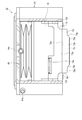
- FIG. 1 is a perspective view showing a configuration of a blood pressure measurement device according to an embodiment of the present invention.
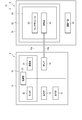
- FIG. 2 is a block diagram showing the configuration of the blood pressure measurement device.
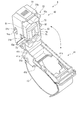
- FIG. 3 is a perspective view showing a configuration of a sensor device of the blood pressure measurement device.
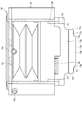
- FIG. 4 is a perspective view showing a configuration of a part of the sensor device of the blood pressure measurement device.
- FIG. 5 is a perspective view showing a configuration of a sensor unit of the blood pressure measurement device.
- FIG. 6 is a plan view showing the configuration of the sensor unit.
- FIG. 7 is a cross-sectional view showing a configuration in which the sensor module and the air bag of the sensor unit are cut along the VII-VII line cross section shown in FIG. FIG.
- FIG. 8 is a cross-sectional view showing a configuration in which the sensor module and the air bag of the sensor unit are cut along the section VIII-VIII shown in FIG.
- FIG. 9 is a cross-sectional view showing a configuration of the sensor module and the air bag of the sensor unit cut along the line IX-IX shown in FIG.
- FIG. 10 is a cross-sectional view showing a configuration of the blood pressure measurement device.
- FIG. 11 is a cross-sectional view showing a configuration of the blood pressure measurement device.
- FIG. 12 is a cross-sectional view showing a configuration of the blood pressure measurement device.
- FIG. 13 is a cross-sectional view showing a configuration of a sensor module of the sensor unit.
- FIG. 14 is a cross-sectional view showing the configuration of the sensor module.
- FIG. 15 is a perspective view showing a sensor base of the sensor module.
- FIG. 16 is a plan view showing a configuration of a sensor module of the sensor unit.
- FIG. 17 is an explanatory diagram showing position adjustment of the sensor unit of the blood pressure measurement device.
- FIG. 18 is a flowchart showing an example of the manufacturing method of the sensor module.
- FIG. 19 is a flowchart showing an example of blood pressure measurement using the blood pressure measurement device.
- FIG. 20 is an explanatory diagram showing an example of blood pressure measurement using the blood pressure measurement device.
- FIG. 21 is an explanatory diagram showing an example of blood pressure measurement using the blood pressure measurement device.
- FIG. 22 is an explanatory diagram showing an example of blood pressure measurement using the blood pressure measurement device.
- FIG. 23 is a perspective view showing a configuration of a blood pressure measurement device according to another embodiment of the present invention.
- FIG. 24 is a block diagram showing a configuration of the blood pressure measurement device.
- FIG. 25 is a perspective view showing a configuration of a blood pressure measurement device according to another embodiment of the present invention.
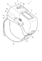
- FIG. 1 is a perspective view showing a configuration of a blood pressure measurement device 1 according to an embodiment of the present invention with a main body fixture 16 closed.
- FIG. 2 is a block diagram illustrating a configuration of the blood pressure measurement device 1.
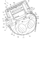
- FIG. 3 is a perspective view showing the configuration of the sensor device 5 of the blood pressure measurement device 1 with the sensing body 42 opened.
- FIG. 4 is a perspective view illustrating a configuration in which the sensor unit 52 is removed from the sensor device 5 of the blood pressure measurement device 1.
- FIG. 5 is a perspective view showing the configuration of the sensor unit 52 of the blood pressure measurement device 1.
- FIG. 6 is a plan view showing the configuration of the sensor unit 52.
- FIG. 7 is a cross-sectional view showing the configuration of the sensor module 63 and the air bag 62 of the sensor unit 52 taken along the line VII-VII shown in FIG.
- FIG. 8 is a cross-sectional view showing the configuration of the sensor module 63 and the air bag 62 of the sensor unit 52 taken along the line VIII-VIII shown in FIG.
- FIG. 9 is a cross-sectional view showing the configuration of the sensor module 63 and the air bladder 62 of the sensor unit 52 taken along the line IX-IX.
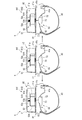
- FIG. 10 is a cross-sectional view showing the configuration of the blood pressure measurement device 1.
- FIG. 11 is a cross-sectional view showing the configuration of the blood pressure measurement device 1.
- FIG. 12 is a cross-sectional view showing the configuration of the blood pressure measurement device 1.
- FIG. 13 is a cross-sectional view showing a state in which the configuration of the sensor module 63 of the sensor unit 52 is cut along a cross section along the direction in which the pressure sensitive elements 71 c of the pressure sensor unit 71 are arranged.
- FIG. 14 is a cross-sectional view showing a state in which the configuration of the sensor module 63 is cut along a cross section along a direction orthogonal to the direction in which the pressure sensitive elements 71c are arranged.
- FIG. 15 is a perspective view showing the sensor base 72 of the sensor module 63.
- FIG. 16 is a plan view showing the configuration of the sensor module 63 of the sensor unit 52.
- the radial artery of the wrist 100 is denoted by 110
- the radial bone is denoted by 111
- the ulnar artery is denoted by 112
- the ulna is denoted by 113
- the tendon is denoted by 114.
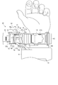
- the blood pressure measurement device 1 is an electronic blood pressure measurement device that is attached to a wrist 100 of a living body and calculates a blood pressure value from the pressure of the radial artery 110. As shown in FIGS. 1 to 16, the blood pressure measurement device 1 includes a device body 4 and a sensor device 5. For example, in the blood pressure measurement device 1, the sensor device 5 is attached to a region of the wrist 100 where the radial artery 110 exists, and the device body 4 is attached to the wrist 100 adjacent to the elbow side of the sensor device 5.
- Such a blood pressure measurement device 1 measures the pressure pulse wave pressure for each heartbeat that changes in conjunction with the heartbeat of the radial artery 110 by compressing the radial artery 110 with the sensor device 5, and the measured pressure Is processed by the apparatus main body 4 based on the tonometry method to determine the blood pressure.
- the apparatus main body 4 includes a main body case 11, an operation unit 12, a display unit 13, a pump 14, a control board 15, and a main body fixture 16. Further, for example, the apparatus main body 4 may be configured to include a cuff in the main body fixture 16 and press the wrist 100 during blood pressure measurement.
- the main body case 11 accommodates a part of the operation unit 12, a part of the display unit 13, and the control board 15, and exposes a part of the operation unit 12 and a part of the display unit 13 from the outer surface.
- the main body case 11 is attached with a main body fixing tool 16.
- the operation unit 12 is configured to be able to input a command from the user.
- the operation unit 12 includes a plurality of buttons 21 provided on the main body case 11 and a sensor that detects an operation of the buttons 21.
- the operation unit 12 may be a touch panel and may be provided on the display unit 13.
- the operation unit 12 converts a command into an electric signal when operated by a user.
- the sensor that detects the operation of the button 21 is electrically connected to the control board 15 and outputs an electrical signal to the control board 15.
- the display unit 13 is disposed on the main body case 11 so as to be exposed from the outer surface of the main body case 11.
- the display unit 13 is electrically connected to the control board 15.
- the display unit 13 is, for example, a liquid crystal display or an organic electroluminescence display.
- the display unit 13 displays various information including blood pressure values such as date and time, maximum blood pressure, and minimum blood pressure, and measurement results such as heart rate.
- the pump 14 is, for example, a piezoelectric pump.
- the pump 14 has a tube 14a connected to the sensor device 5, compresses air, and supplies the compressed air to the sensor device 5 through the tube 14a.
- the pump 14 is electrically connected to the control board 15.
- the control board 15 includes, for example, a communication unit 31, a storage unit 32, and a control unit 33.
- the control board 15 is configured by mounting the communication unit 31, the storage unit 32, and the control unit 33 on the board.
- the control board 15 is connected to the sensor device 5 via a cable 15a.
- the cable 15 a is disposed outside the main body case 11 through a part of the outer surface of the main body case 11.
- the cable 15 a is arranged in the sensor device 5 from the inside of the main body case 11 through an opening provided on the side surface of the main body case 11.
- the communication unit 31 is configured to be able to transmit and receive information with an external device wirelessly or by wire.
- the communication unit 31 transmits, for example, information controlled by the control unit 33 and information such as measured blood pressure value and pulse to an external device via a network, and software from the external device via the network.
- An update program is received and sent to the control unit.
- the network is, for example, the Internet, but is not limited thereto, and may be a network such as a LAN (Local Area Network) provided in a hospital, or a predetermined standard such as USB. It may be a direct wired communication with an external device using a cable having a terminal. Therefore, the communication unit 31 may include a plurality of wireless antennas and micro USB connectors.
- LAN Local Area Network
- USB Universal Serial Bus
- the storage unit 32 calculates a blood pressure value and a pulse from program data for controlling the entire blood pressure measurement device 1, setting data for setting various functions of the blood pressure measurement device 1, and pressure measured by the pressure-sensitive element 71c.
- the calculation data and the like for this are stored in advance. Further, the storage unit 32 stores information such as the calculated blood pressure value, the pulse, and time series data in which these calculated data are associated with time.
- the control unit 33 is configured by, for example, a single or a plurality of CPUs (Central Processing Unit), and controls the operation of the entire blood pressure measurement device 1 and performs each process based on the program data.
- the control unit 33 is electrically connected to the operation unit 12, the display unit 13, the pump 14, and the sensor device 5, and controls the operation of each component, transmits / receives signals, or supplies power.
- the main body fixing tool 16 includes, for example, one or a plurality of band-shaped bands and a fixing member such as a hook-and-loop fastener that wraps the band around the wrist 100 and fixes the main body case 11 to the wrist 100.
- a fixing member such as a hook-and-loop fastener that wraps the band around the wrist 100 and fixes the main body case 11 to the wrist 100.
- blood pressure data is continuously formed from the pulse wave of the radial artery 110 detected by the sensor device 5 by the control unit 33 performing processing using the program data stored in the storage unit 32.
- the blood pressure data includes blood pressure waveform data corresponding to the measured pulse wave waveform.
- the blood pressure data may further include time-series data of blood pressure feature amounts (blood pressure values).
- blood pressure feature amount include, but are not limited to, systolic blood pressure (SBP) and diastolic blood pressure (DBP; Diastolic Blood Blood Pressure).
- SBP systolic blood pressure
- DBP diastolic blood pressure
- the maximum value in the pulse waveform for one heartbeat corresponds to systolic blood pressure
- the minimum value in the pulse waveform for one heartbeat corresponds to diastolic blood pressure.
- the apparatus main body 4 measures a pressure pulse wave as a pulse wave by a tonometry method.
- the tonometry method is a method in which the radial artery 110 is pressed from above the skin with an appropriate pressure to form a flat portion in the artery, and the sensor device 5 performs pressure in a state where the inside and outside of the radial artery 110 are balanced.
- a method for measuring pulse waves According to the tonometry method, blood pressure values for each heartbeat can be obtained.
- the sensor device 5 includes an attach part 41, a sensing body 42, and a fixture 43.
- the attachment part 41 has a shape in which one main surface follows the circumferential direction of the wrist 100 in the region where the radial artery 110 of the wrist 100 of the left hand exists.
- the attachment part 41 is provided on the base 41a, an opening 41b formed in the base 41a, and a base 41a in which a region in contact with the wrist 100 is curved following the shape of the wrist 100 in the circumferential direction.
- a cushion 41d provided on the main surface of the base 41a that comes into contact with the wrist 100 of the base 41a.
- the base 41a is configured to be long in one direction.
- the base 41a is disposed on the palm side of the wrist 100 and on the side of the wrist 100 on the side of the rib 111, and in the circumferential shape of the palm of the wrist 100 and the side of the wrist 100 on the side of the rib 111.
- the main surface arranged on the wrist 100 side is curved.
- the base 41 a abuts at least the main surface on the outer peripheral edge side with the sensing body 42.
- the opening 41b is provided on the center side of the base 41a, and is formed in a size that allows one or more fingers to be arranged. That is, the opening 41b can palpate a region where the radial artery 110 of the wrist 100 exposed from the opening 41b exists with a finger when the sensor device 5 is attached to the wrist 100, and a part of the sensing body 42 is It is formed in a size that can contact the wrist 100.
- the mounting portion 41c is a main surface opposite to the surface facing the wrist 100 of the base portion 41a, and is provided on one end side in the longitudinal direction of the base portion 41a.
- the attachment portion 41c is configured to hold the sensing body 42 and to move the sensing body 42 in a direction away from the base portion 41a and a direction approaching the base portion 41a.
- the attachment portion 41c is a shaft support portion that supports the sensing body 42 so as to be rotatable about one axis.
- the attachment portion 41c is formed integrally with the base portion 41a.
- the cushion 41d is, for example, an elastic body configured in a sheet shape with a foamable resin material provided on a main surface that comes into contact with the wrist 100 of the base 41a.
- the cushion 41d protects the wrist 100 by elastically deforming, for example, when the blood pressure measurement device 1 is attached to the wrist 100.
- the sensing main body 42 includes a case 51, a sensor unit 52, and an adjusting unit 53 that adjusts the position of the sensor unit 52.
- the case 51 is configured, for example, in a rectangular box shape with a surface facing the attachment part 41 being opened.
- the case 51 holds the sensor unit 52 and the adjusting means 53.
- the case 51 is attached to the attachment portion 41c so as to be able to reciprocate in a direction away from the base portion 41a.
- the case 51 includes a rotation shaft 51a that is rotatably provided on the attachment portion 41c.
- the case 51 has an engagement portion 51b that fixes the case 51 to the base portion 41a when it contacts the base portion 41a.
- the engaging portion 51b is, for example, a protrusion that engages with an opening provided in the base portion 41a, and is configured to be disengaged from the opening of the base portion 41a when operated.
- the case 51 includes a first hole 51c in which the tube 14a is disposed, a second hole 51d in which the cable 15a is disposed, a third hole 51e that movably supports a part of the adjusting means 53, and a sensor.
- the first hole 51c and the second hole 51d are provided on the same side wall of the case 51 adjacent to the apparatus body 4 when the first hole 51c and the second hole 51d are attached to the wrist 100.
- 3rd hole 51e is provided in the side wall opposite to the side wall of case 51 in which the 1st hole 51c and the 2nd hole 51d are provided.
- the third hole 51 e is a rectangular opening that extends linearly in the longitudinal direction of the case 51, in other words, when the sensor device 5 is attached to the wrist 100.
- the guide groove 51f is provided on the inner surface side of the side wall of the case 51 in which the third hole 51e is provided.
- the guide groove 51f includes a first groove 51f1 extending from the opening end of the case 51 to a midway toward the top wall facing the opening, and a first groove 51f extending in a direction orthogonal to the first groove 51f1. 2 grooves 51f2.
- One end of the second groove 51 f 2 is continuous with the first groove 51 f 1, and one end to the other end extends toward one side in the longitudinal direction of the case 51.
- the sensor unit 52 includes a movable case 61, an air bag 62, a sensor module 63, and a movable base 64 that holds the sensor module 63 movably in one direction with respect to the movable case 61.
- the sensor unit 52 is held by the case 51 so as to be movable within a predetermined range along the longitudinal direction of the case 51 by the adjusting means 53.
- the movable case 61 accommodates the sensor module 63 and the movable base 64, and holds the movable base 64 holding the sensor module 63 movably toward the opening 41b of the attach portion 41.
- the movable case 61 is held in the case 51 so as to be movable along the longitudinal direction of the case 51.
- the movable case 61 is configured in a rectangular box shape in which a surface facing the attachment portion 41 that houses the air bag 62 and the sensor module 63 is opened.
- the movable case 61 accommodates an air bag 62, a sensor module 63 and a movable base 64.
- the movable case 61 has an air bag 62 disposed between the top wall and the movable base 64.
- the movable case 61 holds the movable base 64 movably in one direction so that the sensor module 63 can protrude and retract from the opening of the movable case 61.
- the movable case 61 has a guide protrusion 61a that is arranged so that the guide groove 51f can be moved on the outer surface of the side wall of the case 51 that faces the side wall where the guide groove 51f is provided, and a fixed portion to which a part of the adjusting means 53 is fixed. 61b. As the guide protrusion 61 a moves along the second groove 51 f 2, the movable case 61 moves along the longitudinal direction of the case 51.
- the air bag 62 has a bellows structure.
- the air bladder 62 is fluidly connected to the pump 14 via the tube 14a. As shown in FIGS. 7 to 12, the air bag 62 expands in a direction from the top wall of the movable case 61 toward the opening.
- the air bag 62 is inflated so that the sensor module 63 protrudes from the opening of the movable case 61 from the position where the sensor module 63 is accommodated in the movable case 61 and touches the wrist 100 from the opening 41b of the attachment part 41. Until the sensor module 63 is moved.
- the air bag 62 is formed of polyurethane, for example.
- the sensor module 63 includes a pressure sensor unit 71, a sensor base 72 that holds the pressure sensor unit 71, a region that covers the sensor base 72 and faces the pressure sensor unit 71.
- a sensor head cover 73 having an opening 73a and a soft portion 74 are provided.
- the sensor module 63 is disposed in the movable case 61 and is held by the movable case 61 so as to be movable within a predetermined movement range along the direction in which the top wall of the movable case 61 and the opening are opposed. That is, the sensor module 63 is held movably in the movable case 61 and its movement is restricted by a restriction means such as a stopper when the sensor module 63 is moved to a position protruding beyond a certain amount from the opening of the movable case 61.
- the pressure sensor unit 71 includes a flexible substrate 71a, a substrate 71b mounted on the flexible substrate 71a, and a plurality of pressure sensitive elements 71c mounted on the substrate 71b.
- the pressure sensor unit 71 is fixed on one main surface of the sensor base 72.
- the flexible substrate 71a is bonded and fixed on the sensor base 72 via an adhesive sheet 71f, for example.
- a predetermined circuit pattern is formed on one main surface of the flexible substrate 71a.
- a substrate 71b is mounted on the flexible substrate 71a.
- a cable 15a is connected to the circuit pattern of the flexible substrate 71a.
- the cable 15a is composed of, for example, a flexible substrate. That is, the flexible board 71a is electrically connected to the control board 15 via the cable 15a.
- the substrate 71b is electrically connected to the flexible substrate 71a.
- the board 71b is electrically connected to the control board 15 via the flexible board 71a and the cable 15a.
- the substrate 71b is configured as a rectangular plate.
- the plurality of pressure sensitive elements 71c are mounted on the substrate 71b.
- the plurality of pressure sensitive elements 71c are electrically connected to the circuit pattern on the flexible substrate 71a. That is, the plurality of pressure sensitive elements 71c are electrically connected to the control board 15 via the board 71b, the flexible board 71a, and the cable 15a.
- the substrate 71b and the plurality of pressure sensitive elements 71c constitute a sensor chip.
- a plurality of pressure sensitive elements 71c are arranged in one direction to constitute a pressure sensitive element row 71d.
- One or more pressure-sensitive element rows 71d are provided.
- the plurality of pressure sensitive element rows 71d are arranged at predetermined intervals in a direction orthogonal to the direction in which the plurality of pressure sensitive elements 71c are arranged.
- the pressure sensitive element rows 71d are formed in two rows as an example in the present embodiment.
- the pressure sensor unit 71 is disposed on the sensor base 72 so that one direction in which the plurality of pressure sensitive elements 71 c are disposed is the width direction of the wrist 100.
- the pressure sensor unit 71 transmits pressure values measured by the plurality of pressure sensitive elements 71c to the control board 15 via the cable 15a.
- the sensor base 72 is made of, for example, a synthetic resin.
- the sensor base 72 integrally includes a support wall portion 72a and a peripheral wall portion 72b erected from the outer peripheral edge of the support wall portion 72a on the back side opposite to the living body.
- the sensor base 72 holds the pressure sensor unit 71 and the cable 15 a connected to the pressure sensor unit 71.
- the support wall 72a is formed in a rectangular plate shape having a predetermined thickness.
- the wrist 100 side of the support wall portion 72a is defined as the surface side.
- the support wall portion 72a holds the pressure sensor portion 71 in a region facing the opening 73a of the sensor head cover 73 on the main surface 72a1 on the front surface side.
- a groove 76 is formed so that the support wall 72a is convex on the wrist 100 side.
- the groove portion 76 is configured such that the sensor head cover 73 can be fitted therein.
- a pressure sensor unit 71 is fixed to the main surface 72a1 via an adhesive sheet 71f.
- a plurality of holes (flow holes) 72d are formed in the support wall 72a, for example.
- the plurality of holes 72d penetrate the support wall 72a in the thickness direction, and open to the main surface 72a1 and the other main surface 72a2.
- the plurality of holes 72d are formed so that the material forming the soft portion 74 can flow. For example, four holes 72d are formed. The hole 72d communicates with a gap 79 described later.
- the pressure sensor portion 71 is fixed to the main surface 72a1 of the support wall portion 72a, and a part of the pressure sensor portion 71 faces the hole 72d.
- a communicating portion 71g communicating with the hole 72d and the gap 79 is formed at a position facing the hole 72d in the pressure sensor portion 71.
- the communication part 71g is, for example, a hole.
- the communication portion 71g has a hole 71f1 formed in the adhesive sheet 71f and a hole 71a3 formed in the flexible substrate 71a.
- the communication portion 71g is not limited to a hole. For example, it may be a notch.
- the hole 72d may be opened at a position on the main surface 72a1 away from the pressure sensor unit 71.
- the communication part 71g is not formed.
- the communication of the hole 72d with the gap portion 79 includes communication through the communication portion 71g and direct communication.
- the peripheral wall portion 72b is erected from the outer periphery of the support wall portion 72a on the side opposite to the living body.
- the peripheral wall portion 72 b is fixed to the movable base 64.
- the sensor head cover 73 comes into contact with the wrist 100 at the end surface on the wrist 100 side.
- the opening 73a is formed on the end face.
- the opening 73a is formed in a rectangular shape, for example.
- the sensor head cover 73 is made of, for example, a synthetic resin material.
- the sensor head cover 73 integrally includes a convex portion 73b having an opening 73a and a frame portion 73c erected on the sensor base 72 side from the periphery of the convex portion 73b. At least a part of the opposing surfaces of the sensor head cover 73 and the sensor base 72 are separated from each other, and a gap 79 is formed between the inner surface 73 g of the sensor head cover 73, the sensor base 72, and the pressure sensor portion 71.
- the convex portion 73b is configured in a rectangular plate shape, for example.
- An end surface (planar portion) 73d which is the main surface of the convex portion 73b on the living body side, is formed in a plane.
- the end surface 73d becomes a part of a region in contact with the wrist 100 on the outer surface of the sensor module 63 when the blood pressure measurement device 1 is used.
- the convex part 73b has the end surface 73d and the surrounding surface 73e which continues to the end surface 73d.
- the peripheral surface 73e is a surface along the thickness direction of the convex portion 73b.
- a ridge between the peripheral surface 73e and the end surface 73d is formed into a curved surface.
- a corner portion of the peripheral surface 73e is formed into a curved surface.
- a ridge between the peripheral surface 73e and the end surface 73d and a part of the peripheral surface 73e become a part of a region in contact with the wrist 100 on the outer surface of the sensor module 63 when the blood pressure measurement device 1 is used.
- the area of the outer surface of the sensor head cover 73 that contacts the wrist 100 varies depending on the shape of the sensor head cover 73 and the pressing force of the sensor head cover 73 on the wrist 100.
- the sensor head cover 73 has a convex portion 73b as an example. Therefore, the end surface 73d, the ridge between the end surface 73d and the peripheral surface 73e, and a part of the peripheral surface 73e are the same as the sensor head cover 73.
- An example of a region in contact with the wrist 100 on the outer surface is configured.
- the surface roughness of the outer surface that constitutes the region in contact with the wrist 100 on the outer surface of the sensor head cover 73 is lower than the surface roughness of the inner surface 73g of the sensor head cover 73 that constitutes the gap portion 79.
- the surface roughness of the inner surface 73g is rougher than the surface roughness of the outer surface that constitutes the region in contact with the wrist 100 on the outer surface of the sensor head cover 73.
- the surface roughness of the end surface 73d, the surface roughness of the ridge between the end surface 73d and the peripheral surface 73e, and the partial surface roughness of the peripheral surface 73e are the surface roughness of the inner surface 73g. Less than that.
- the surface roughness of the region in contact with the wrist 100 on the outer surface of the sensor head cover 73 is the same.
- the surface roughness of the entire outer surface of the sensor head cover 73 may be lower than the surface roughness of the inner surface 73g of the sensor head cover 73.
- the end surface 73d, the ridge between the end surface 73d and the peripheral surface 73e, and a part of the peripheral surface 73e, which are regions in contact with the wrist 100 on the outer surface of the sensor head cover 73, are mirror-finished.
- the entire surface of the outer surface of the sensor head cover 73 may be mirror-finished.
- a fitting portion 73f that fits into the groove portion 76 of the sensor base 72 is provided at one end of the frame portion 73c on the sensor base 72 side.
- the inner surface 73g is composed of an inner surface of the opening 73a, a surface of the convex portion 73b on the pressure sensor portion 71 side, and an inner surface of the frame portion 73c.
- the inner surface 73g is formed in a concavo-convex shape. As an example, the inner surface 73g is formed in an uneven shape by increasing the surface roughness.
- the surface roughness of the inner surface 73g is a surface roughness where the area of the inner surface 73g is an area where the holding force for holding the soft portion 74 can be improved.
- the surface roughness of the inner surface 73g can be increased by increasing the surface roughness of the mold that forms the sensor head cover 73, for example.
- the surface roughness of the inner surface 73g can be made rough by applying predetermined surface processing to the inner surface 73g.
- the predetermined processing for example, by applying a chemical to the inner surface 73g, the surface roughness of the inner surface 73g may be roughened by the chemical.
- the sensor head cover 73 may be formed from ceramics. By forming the sensor head cover 73 with ceramics, the surface roughness of the inner surface 73g can be roughened by utilizing the surface roughness of the inner surface 73g that has not been subjected to surface treatment.
- the surface roughness of the inner surface 73g is rougher than the surface roughness of the end surface 73d where the opening 73a of the sensor head cover 73 is formed.
- the soft part 74 is provided in the gap part 79.
- the soft portion 74 is configured so as to fill at least the opening 73 a and cover the pressure sensor portion 71 and transmit the pressure of the radial artery 110 to the pressure sensor portion 71.
- the soft part 74 is filled in the range from the opening 73a to the adhesive sheet 71f of the gap part 79 as an example. Note that a part of the sensor head cover 73 is in contact with the adhesive sheet 71f as shown in FIG. 13, and the other part is not in contact with the adhesive sheet 71f as shown in FIG. For this reason, a part of the soft part 74 is located at a position beyond the adhesive sheet 71f as shown in FIG.
- the soft part 74 is filled in the gap 79 from the opening 73a to the adhesive sheet 71f, so that the soft part 74 is filled in the opening 73a, and the flexible sensor 71a, the board 71b, And all the pressure sensitive elements 71c are covered with the soft part 74, and the soft part 74 is closely_contact
- the soft portion 74 is formed by injecting a relatively soft resin material such as silicone resin into the gap 79 from the main surface 72a2 side through the hole 72d.
- a relatively soft resin material such as silicone resin
- the opening 73a is closed by bringing the smooth surface 81a of the counter plate 81 into contact with the end surface 73d.
- An end surface 74 a that contacts the wrist 100 of the soft portion 74 is formed following the smooth surface 81 a of the counter plate 81. That is, the surface roughness of the end surface 74a is managed by the smooth surface 81a. For this reason, the surface roughness of the smooth surface 81a is set based on the surface roughness required for the end surface 74a.
- the end surface 74 a of the soft portion 74 is configured to be flush with the end surface 73 d of the sensor head cover 73.
- the soft part 74 may be formed of a material that comes into contact with the wrist 100 and is capable of detecting the pressure of the radial artery 110 with the pressure-sensitive element 71c. Can be set as appropriate.
- the adjusting means 53 is configured to be able to adjust the position of the sensor unit 52 with respect to the case 51 in the circumferential direction of the wrist 100 as shown in FIG.
- the adjustment means 53 has an adjustment knob 53a that is located on the outer surface of the case 51 and that is partly fixed to the fixed portion 61b of the movable case 61 via the third hole 51e.
- the adjustment means 53 includes a scale 53b provided adjacent to the third hole 51e of the case 51, and an instruction part 53c provided on the adjustment knob 53a and pointing to the scale 53b.
- the adjustment knob 53 a is connected to the sensor unit 52 by being fixed to the movable case 61.
- the adjustment knob 53a is configured to be able to move the sensor unit 52. That is, the adjustment means 53 moves the sensor unit 52 along the second groove 51f2 by moving the adjustment knob 53a in the longitudinal direction of the third hole 51e, and adjusts the position with respect to the case 51. It is an adjustment mechanism.
- the scale 53b and the instruction unit 53c are display units that display the position of the adjustment knob 53a, that is, the position of the sensor unit 52 connected to the adjustment knob 53a in a visible manner.
- the fixing tool 43 includes, for example, one or a plurality of band-shaped bands and a fixing member such as a hook-and-loop fastener that wraps the band around the wrist 100 and fixes the attachment part 41 and the sensing body 42 to the wrist 100.
- the fixing tool 43 may be comprised by the 1st belt called the parent which has a buckle, and the 2nd belt called the sword tip fixed to a buckle.
- the fixing tool 43 may further have a configuration for fixing the case 51 to the attachment portion 41 by being wound around the case 51.
- the repulsive force when the sensor module 63 presses the wrist 100 due to the expansion of the air bag 62 is applied to the movable case 61, and the adjustment knob 53a directly or from the movable case 61 by the movable case 61. It may be possible to prevent the case 51 from being indirectly pressed via the movement of the case 51 in a direction away from the attachment portion 41.
- FIG. 18 is a flowchart illustrating an example of a method for manufacturing the sensor module 63.
- the manufacturing method of the sensor module 63 includes a sensor setting process (step ST11) for setting the pressure sensor unit 71 on the sensor base 72, a cover assembly process (step ST12) for mounting the sensor head cover 73 to the sensor base 72, and an opening.
- a plurality of pressure sensitive elements 71c are mounted on the substrate 71b.
- the substrate 71b on which the plurality of pressure sensitive elements 71c are mounted is mounted on the flexible substrate 71a. Thereby, the pressure sensor unit 71 is completed.
- the pressure sensor unit 71 is fixed on the sensor base 72 via the adhesive sheet 71f.
- the sensor head cover 73 is placed on the sensor base 72 as a cover assembling step (step ST12).
- the pressure sensor unit 71 is disposed in an area corresponding to the opening 73 a of the sensor head cover 73.
- a gap 79 is formed between the sensor base 72 and the sensor head cover 73.
- a filling process (step ST13) is performed.
- a filling step first, in a state where the sensor base 72 and the sensor head cover 73 are assembled, the integrated body is brought into a posture in which the opening 73a is downward in the direction of gravity, and the opening 73a is formed by the smooth surface 81a of the counter plate 81. Block it.
- the smooth surface 81 a of the counter plate 81 is configured to have a surface roughness set based on the surface roughness required for the end surface 74 a of the soft portion 74.
- the nozzle 82 that flows out the soft resin material that is the material of the soft portion 74 is inserted into the hole 72d from the main surface 72a2 side, and a predetermined amount of the material of the soft portion 74 is supplied from the hole 72d.
- the material flows into the gap 79 from the hole 72d due to its own weight, for example, and reaches the opening 73a.
- the material of the soft part 74 supplied to the gap part 79 including the opening 73a forms the soft part 74.
- the counter plate 81 is removed at a predetermined timing.
- the soft portion 74 may be formed by performing a cooling treatment or a heat treatment according to the type of material of the soft portion 74. Further, after removing the opposing plate 81, the surface treatment of the end surface 74a of the soft portion 74 may be performed.
- the sensor module 63 is completed.
- FIG. 19 is a flowchart showing an example of blood pressure measurement using the blood pressure measurement device 1, and shows both the user's operation and the operation of the control unit 33.
- 20 to 22 are explanatory diagrams illustrating an example of blood pressure measurement using the blood pressure measurement device 1.
- the user searches for the position of the radial artery 110 on the wrist 100 by palpation (step ST21).
- the skin on the radial artery 110 may be marked by drawing a line with a pen.
- the user moves the sensing body 42 of the sensor device 5 away from the attachment unit 41.
- the user operates the engagement portion 51b to release the fixing of the case 51 and the base portion 41a, and rotates the sensing body 42 around the rotation shaft 51a in a direction away from the attachment portion 41.
- the user wears the apparatus main body 4 and the sensor apparatus 5 (step ST22).
- the user passes the wrist 100 through the body fixture 16 of the device body 4 and the fixture 43 of the sensor device 5, and places the device body 4 and the sensor device 5 at predetermined positions on the wrist 100.
- the main body fixing tool 16 of the apparatus main body 4 is tightened to fix the apparatus main body 4 to the wrist 100.
- the body fixing tool 16 of the apparatus main body 4 is configured to have a cuff, the skin of the wrist 100 is not sandwiched between the body fixing tool 16 (cuff) and the body fixing tool 16 (cuff) is Check for looseness.
- the position of the sensor device 5 is adjusted so that the opening 41 b of the attach portion 41 of the sensor device 5 is located at the radial artery 110 of the wrist 100. Further, the user fixes the sensor device 5 to the wrist 100 by tightening the fixture 43 of the sensor device 5 while maintaining the radial artery 110 positioned in the opening 41b.
- the user palpates the wrist 100 from the opening 41b of the attachment unit 41 (step ST23), and confirms again that the radial artery 110 is located in the opening 41b.
- the user rotates the sensing main body 42 in a direction close to the attachment portion 41 and fixes the sensing main body 42 to the attachment portion 41 by the engaging portion 51 b.
- the position of the sensing body 42 is adjusted by operating the adjustment knob 53a.
- the control unit 33 measures the blood pressure based on the blood pressure measurement command (step ST24). At this time, the control unit 33 drives and controls the pump 14 to inflate the air bag 62, so that the sensor module 63 is gradually housed in the movable case 61 as shown in FIGS.
- the sensor head cover 73 and the soft part 74 of the sensor module 63 press the region where the radial artery 110 of the wrist 100 exists.
- the radial artery 110 is pressed with an appropriate pressure, so that a flat part is formed in the radial artery 110.
- each pressure sensitive element 71c of the pressure sensor unit 71 measures a pressure pulse wave.
- the control unit 33 obtains the blood pressure by the tonometry method from the pressure pulse wave of the radial artery 110 detected by the pressure sensor unit 71. Prior to blood pressure measurement, the control unit 33 may perform blood pressure measurement for calibration based on the program data stored in the storage unit 32, and the mounting state and pressure of the device main body 4 and the sensor device 5 may be measured. You may determine whether the position of the sensor part 71 is correct.
- the inner surface 73g of the sensor head cover 73 can be increased in area by being configured in an uneven shape. For this reason, since the adhesion area of the inner surface 73g and the soft part 74 can be increased, the retention strength of the soft part 74 of the inner surface 73g can be improved. For this reason, the blood pressure measurement device 1 can make it difficult to peel the soft portion 74 from the inner surface 73g.
- the surface area of the inner surface 73g can be increased and the holding power of the soft portion 74 can be improved.
- the soft portion 74 is manufactured, the soft portion 74 attached to the end surface 73d is removed even if a small amount of material forming the soft portion 74 leaks from between the opening 73a and the counter plate 81, for example. It becomes easy to peel off the material to be formed.
- the surface roughness of the end surface 73d is lower than the surface roughness of the inner surface 73g, the user can feel better when the sensor module 63 is pressed against the wrist 100 when the blood pressure measuring device 1 is used.
- the end surface 73d is a mirror-finished surface, dirt is less likely to adhere to the end surface 73d. Furthermore, when the soft part 74 is manufactured, even if a small amount of material forming the soft part 74 leaks from between the opening 73a and the counter plate 81, for example, the material of the soft part 74 attached to the end face 73d. Can be removed more easily. Furthermore, when the sensor module 63 is pressed against the wrist 100, the user's feeling can be further improved.
- the surface roughness of the entire area of the outer surface of the sensor head cover 73 in contact with the wrist 100 the same as the surface roughness, that is, the end face 73d, when the sensor module 63 is pressed against the wrist, The touch can be made even better.
- the surface roughness of the inner surface 73g of the sensor head cover 73 in a state where the surface treatment is not performed is made rough by using the surface roughness of the inner surface 73g. It becomes possible to do.
- the soft part 74 is manufactured by injecting a material from the hole 72d using the counter plate 81, the soft part 74 can be manufactured by a simple process. Furthermore, it is possible to form the end surface 74 a of the soft portion 74 flush with the end surface 73 d of the sensor head cover 73 simply by injecting the material.
- the wrist 100 can be palpated while the sensor device 5 is worn, so whether or not the sensor device 5 is worn at a predetermined position. Can be easily determined. That is, it is possible to palpate the wrist 100 from the opening 41b, and when the sensor device 5 of the blood pressure measurement device 1 is attached to the wrist 100, the radial artery 110 is temporarily attached to the wrist 100 while the sensor device 5 is temporarily attached to the wrist 100. By searching through palpation, the position of the sensor device 5 can be adjusted, and then it can be fully mounted. As a result, it is easy to attach the blood pressure measurement device 1 to an appropriate position.
- the radial artery 110 can be further operated by operating the adjusting knob 53a. Since the position of the sensor unit 52 can be adjusted with respect to the radial artery 110, the pressure of the radial artery 110 can be measured at a suitable position.
- the sensor device 5 is configured such that the sensing body 42 rotates relative to the attachment unit 41 around one axis as a configuration in which the sensing body 42 can move in a direction away from the attachment unit 41. For this reason, when the sensing main body 42 is moved, the sensor module 63 provided in the sensing main body 42 moves in a direction away from the opening 41 b of the attach portion 41.
- the sensor module 63 can be prevented from moving while being in contact with the wrist 100 or the attachment unit 41. More specifically, the sensor unit 52 measures the blood pressure in a state where the sensor head cover 73 and the soft part 74 of the sensor module 63 protrude from the opening of the movable case 61 to a position where the wrist 100 can be appropriately pressed by the air bag 62. Is done.
- the sensing body 42 moves relative to the attachment unit 41 in such a state, the sensing body 42 moves in a direction in which the sensor module 63 is separated from the wrist 100, so that the end surface of the sensor head cover 73 and the soft part 74 are The sensing body 42 does not move while in contact with the wrist 100 or the attachment unit 41. For this reason, when the sensing body 42 is moved, the sensor module 63 can be prevented from being damaged due to interference with other configurations or the wrist 100, and a burden on the wrist 100 can be prevented.
- the sensor device 5 is provided with the opening 41b having a palpable shape in the attach portion 41 and enables the sensing main body 42 to move in a direction away from the attach portion 41 and the wrist 100, whereby the sensor module 63 is provided. Can be prevented, and safety can be improved.
- the attachment portion 41 is provided with the attachment portion 41, and the rotation shaft 51a pivotally supported by the attachment portion 41c is provided.
- a simple configuration provided in the sensing body 42 may be used. For this reason, compared with the structure etc. which are slid to one direction with respect to the attachment part 41, the sensor apparatus 5 becomes a simple structure, and can be manufactured cheaply.
- the sensor device 5 has a configuration in which the sensing body 42 rotates with respect to the attachment portion 41 on one end side in the longitudinal direction of the attachment portion 41, so that substantially the entire area of the upper surface of the attachment portion 41 is exposed to the outside. be able to. For this reason, since all the opening parts 41b of the attachment part 41 are exposed, the shape of the opening part 41b required in order to perform palpation can be made as small as possible. In addition, since the rail structure for sliding the sensing body 42 with respect to the attachment part 41 and the structure for holding the sensing body 42 on the attachment part 41 after the sliding movement are not required, the sensor device 5 is provided in the width direction of the wrist 100. Since the shape of can be made as small as possible, the size can be reduced.
- the inner surface 73g of the sensor head cover 73 is configured to have an uneven shape, thereby increasing the area of the inner surface 73g and the inner surface 73g and the soft part.
- the holding force of the soft part 74 of the inner surface 73g can be improved. For this reason, the blood pressure measurement device 1 can make it difficult to peel the soft portion 74 from the inner surface 73g.
- the blood pressure measurement device 1 has the inner surface 73g formed into a concavo-convex shape by increasing the surface roughness of the inner surface 73g, but is not limited thereto.
- the inner surface 73g may be configured to have a textured shape.
- the inner surface 73g may be configured to have a textured shape by applying a texture to the mold that forms the sensor head cover 73.
- the inner surface 73g may be textured to form a textured shape.
- the inner surface 73g may be roughened while the inner surface 73g is configured to have a textured shape as described above.
- the inner surface 73g may be configured to have an uneven shape other than the embossed shape.
- convex portions such as ribs and bosses may be formed on the inner surface 73g. By forming the convex portions in this way, the area of the inner surface 73g increases.
- the blood pressure measurement device 1 has been described as having a configuration in which the device main body 4 and the sensor device 5 are provided separately, but is not limited thereto.
- the device body 4 and the sensor device 5 may be configured integrally.
- the blood pressure measurement device 1 having such a configuration may be configured such that the operation unit 12, the display unit 13, the pump 14, and the control board 15 used in the device body 4 are provided in the case 51 of the sensing body 42.
- the blood pressure measurement device 1 is configured to move in the direction in which the sensing body 42 moves away from and the direction in which the sensing body 42 moves toward the attachment unit 41, and the sensing body 42 rotates with respect to the attachment unit 41 around one axis.
- the present invention is not limited to this.
- the blood pressure measurement device 1 has a configuration in which the attachment unit 41 and the sensing body 42 are separated from each other as a configuration in which the sensing body 42 moves in a direction away from and a direction in which the sensing body 42 moves toward the attachment unit 41. Also good.
- the engagement portions 51b are provided at a plurality of locations of the case 51 of the sensing body 42, and the sensing body 42 is engaged with the attachment portion 41 at a plurality of positions. do it.
- the blood pressure measurement device 1 measures the pressure of the radial artery 110 and obtains the blood pressure by the tonometry method.
- the configuration is not limited to this, and for example, the pressure measurement device 1 measures the pressure of the ulnar artery 112. It may be.
- requires blood pressure by methods other than the tonometry method may be sufficient as the blood pressure measuring device 1.
- the blood pressure measurement device 1 can move the sensor module 63 in contact with the wrist 100 with respect to the opening 41b of the attachment unit 41 and the wrist 100, and is in contact with the wrist 100 with other configurations. If it is the structure which moves, it can use for the structure which uses another blood-pressure measuring method.
- the opening part 41b of the attachment part 41 was comprised so that palpation was possible, it is not limited to this.
- the opening 41b may be an opening that cannot be palpated.
- sensor unit 53 ... adjusting means 53b ... scale 53c ... indicator 61 ... movable case 61a ... guide protrusion 61b ... Fixed part 62 ... Air bag 63 ... Sensor module 71 ... Pressure sensor part 71a ... Flexible substrate 71b ... Substrate 71c ... Pressure sensitive element 72 ... Sensor base 72a ... Support wall part 2b ... peripheral wall portion 72d ... hole 73 ... sensor head cover 73a ... opening 73b ... convex portion 73c ... frame portion 73d ... end surface 73e ... peripheral surface 73g ... inner surface 74 ... soft portion 74a ... end surface 79 ... gap portion 81 ...
Landscapes
- Health & Medical Sciences (AREA)
- Life Sciences & Earth Sciences (AREA)
- Cardiology (AREA)
- Vascular Medicine (AREA)
- Heart & Thoracic Surgery (AREA)
- Surgery (AREA)
- Biophysics (AREA)
- Pathology (AREA)
- Engineering & Computer Science (AREA)
- Biomedical Technology (AREA)
- Veterinary Medicine (AREA)
- Medical Informatics (AREA)
- Molecular Biology (AREA)
- Physics & Mathematics (AREA)
- Animal Behavior & Ethology (AREA)
- General Health & Medical Sciences (AREA)
- Public Health (AREA)
- Physiology (AREA)
- Ophthalmology & Optometry (AREA)
- Dentistry (AREA)
- Measuring Pulse, Heart Rate, Blood Pressure Or Blood Flow (AREA)
Priority Applications (3)
| Application Number | Priority Date | Filing Date | Title |
|---|---|---|---|
| CN201980027017.7A CN112105291B (zh) | 2018-05-24 | 2019-05-21 | 传感器模块、传感器模块的制造方法以及血压测定装置 |
| DE112019001635.0T DE112019001635T5 (de) | 2018-05-24 | 2019-05-21 | Sensormodul, verfahren zur herstellung eines sensormoduls und blutdruckmessvorrichtung |
| US16/950,333 US11969235B2 (en) | 2018-05-24 | 2020-11-17 | Sensor module, method for manufacturing sensor module, and blood pressure measurement device |
Applications Claiming Priority (2)
| Application Number | Priority Date | Filing Date | Title |
|---|---|---|---|
| JP2018099721A JP7091832B2 (ja) | 2018-05-24 | 2018-05-24 | センサモジュール、センサモジュールの製造方法、及び血圧測定装置 |
| JP2018-099721 | 2018-05-24 |
Related Child Applications (1)
| Application Number | Title | Priority Date | Filing Date |
|---|---|---|---|
| US16/950,333 Continuation US11969235B2 (en) | 2018-05-24 | 2020-11-17 | Sensor module, method for manufacturing sensor module, and blood pressure measurement device |
Publications (1)
| Publication Number | Publication Date |
|---|---|
| WO2019225578A1 true WO2019225578A1 (ja) | 2019-11-28 |
Family
ID=68616997
Family Applications (1)
| Application Number | Title | Priority Date | Filing Date |
|---|---|---|---|
| PCT/JP2019/020044 Ceased WO2019225578A1 (ja) | 2018-05-24 | 2019-05-21 | センサモジュール、センサモジュールの製造方法、及び血圧測定装置 |
Country Status (5)
| Country | Link |
|---|---|
| US (1) | US11969235B2 (https=) |
| JP (1) | JP7091832B2 (https=) |
| CN (1) | CN112105291B (https=) |
| DE (1) | DE112019001635T5 (https=) |
| WO (1) | WO2019225578A1 (https=) |
Cited By (1)
| Publication number | Priority date | Publication date | Assignee | Title |
|---|---|---|---|---|
| US11180101B2 (en) | 2019-02-15 | 2021-11-23 | Honda Motor Co., Ltd. | Sensor attachment structure and energy absorption structure |
Citations (8)
| Publication number | Priority date | Publication date | Assignee | Title |
|---|---|---|---|---|
| JPS5734201U (https=) * | 1980-08-06 | 1982-02-23 | ||
| JPH0614894A (ja) * | 1992-05-12 | 1994-01-25 | Fukuda M Ii Kogyo Kk | 生体用電極 |
| JP2006239114A (ja) * | 2005-03-03 | 2006-09-14 | Citizen Watch Co Ltd | カフレス電子血圧計 |
| JP2010233883A (ja) * | 2009-03-31 | 2010-10-21 | Nippon Zeon Co Ltd | カテーテル |
| JP2011200267A (ja) * | 2010-03-24 | 2011-10-13 | Seiko Epson Corp | センサー装置及び生体情報測定装置 |
| WO2014007307A1 (ja) * | 2012-07-04 | 2014-01-09 | 株式会社アイ・メデックス | 生体電極 |
| JP2016072589A (ja) * | 2014-09-29 | 2016-05-09 | 新科實業有限公司SAE Magnetics(H.K.)Ltd. | 薄膜圧電体素子およびその製造方法並びにそれを有するヘッドジンバルアセンブリ、ハードディスク装置、インクジェットヘッド、可変焦点レンズおよびセンサ |
| WO2017170838A1 (ja) * | 2016-03-31 | 2017-10-05 | 興和株式会社 | 赤外線センサ用集光装置とその製造方法 |
Family Cites Families (9)
| Publication number | Priority date | Publication date | Assignee | Title |
|---|---|---|---|---|
| JPS55111378A (en) | 1979-02-16 | 1980-08-27 | Mitsubishi Electric Corp | Device for running elevator at earthquake |
| JP2613622B2 (ja) | 1988-05-16 | 1997-05-28 | コーリン電子株式会社 | 脈波検出装置 |
| JP3002596B2 (ja) * | 1992-03-17 | 2000-01-24 | 日本コーリン株式会社 | 圧脈波検出装置 |
| JP3002597B2 (ja) * | 1992-03-17 | 2000-01-24 | 日本コーリン株式会社 | 脈波検出プローブの装着装置 |
| US6918879B2 (en) * | 2000-10-09 | 2005-07-19 | Healthstats International Pte. Ltd. | Method and device for monitoring blood pressure |
| JP4614250B2 (ja) * | 2000-11-27 | 2011-01-19 | セイコーインスツル株式会社 | 装着形計測機器 |
| US7674231B2 (en) * | 2005-08-22 | 2010-03-09 | Massachusetts Institute Of Technology | Wearable pulse wave velocity blood pressure sensor and methods of calibration thereof |
| US9110498B2 (en) * | 2010-09-30 | 2015-08-18 | Fitbit, Inc. | Molded wristband case |
| US9401469B2 (en) | 2014-09-29 | 2016-07-26 | Sae Magnetics (H.K.) Ltd. | Thin-film piezoelectric material element, method of manufacturing the same, head gimbal assembly, hard disk drive, ink jet head, variable focus lens and sensor |
-
2018
- 2018-05-24 JP JP2018099721A patent/JP7091832B2/ja active Active
-
2019
- 2019-05-21 DE DE112019001635.0T patent/DE112019001635T5/de active Pending
- 2019-05-21 CN CN201980027017.7A patent/CN112105291B/zh active Active
- 2019-05-21 WO PCT/JP2019/020044 patent/WO2019225578A1/ja not_active Ceased
-
2020
- 2020-11-17 US US16/950,333 patent/US11969235B2/en active Active
Patent Citations (8)
| Publication number | Priority date | Publication date | Assignee | Title |
|---|---|---|---|---|
| JPS5734201U (https=) * | 1980-08-06 | 1982-02-23 | ||
| JPH0614894A (ja) * | 1992-05-12 | 1994-01-25 | Fukuda M Ii Kogyo Kk | 生体用電極 |
| JP2006239114A (ja) * | 2005-03-03 | 2006-09-14 | Citizen Watch Co Ltd | カフレス電子血圧計 |
| JP2010233883A (ja) * | 2009-03-31 | 2010-10-21 | Nippon Zeon Co Ltd | カテーテル |
| JP2011200267A (ja) * | 2010-03-24 | 2011-10-13 | Seiko Epson Corp | センサー装置及び生体情報測定装置 |
| WO2014007307A1 (ja) * | 2012-07-04 | 2014-01-09 | 株式会社アイ・メデックス | 生体電極 |
| JP2016072589A (ja) * | 2014-09-29 | 2016-05-09 | 新科實業有限公司SAE Magnetics(H.K.)Ltd. | 薄膜圧電体素子およびその製造方法並びにそれを有するヘッドジンバルアセンブリ、ハードディスク装置、インクジェットヘッド、可変焦点レンズおよびセンサ |
| WO2017170838A1 (ja) * | 2016-03-31 | 2017-10-05 | 興和株式会社 | 赤外線センサ用集光装置とその製造方法 |
Cited By (1)
| Publication number | Priority date | Publication date | Assignee | Title |
|---|---|---|---|---|
| US11180101B2 (en) | 2019-02-15 | 2021-11-23 | Honda Motor Co., Ltd. | Sensor attachment structure and energy absorption structure |
Also Published As
| Publication number | Publication date |
|---|---|
| CN112105291B (zh) | 2023-08-04 |
| DE112019001635T5 (de) | 2020-12-10 |
| US11969235B2 (en) | 2024-04-30 |
| JP2019201979A (ja) | 2019-11-28 |
| US20210068684A1 (en) | 2021-03-11 |
| JP7091832B2 (ja) | 2022-06-28 |
| CN112105291A (zh) | 2020-12-18 |
Similar Documents
| Publication | Publication Date | Title |
|---|---|---|
| JP7106986B2 (ja) | センサモジュール、血圧測定装置 | |
| US12059236B2 (en) | Blood pressure measurement device | |
| US11529063B2 (en) | Blood pressure measuring device | |
| JP7091832B2 (ja) | センサモジュール、センサモジュールの製造方法、及び血圧測定装置 | |
| WO2019225581A1 (ja) | センサモジュール及び血圧測定装置 | |
| JP7077776B2 (ja) | 血圧測定装置 | |
| US20200323445A1 (en) | Blood pressure measurement device | |
| WO2019225582A1 (ja) | センサモジュール、センサモジュールの製造方法、及び血圧測定装置 | |
| WO2019225586A1 (ja) | 血圧測定装置 | |
| WO2019225585A1 (ja) | 血圧測定装置 | |
| US11653879B2 (en) | Blood pressure measuring device | |
| US20200345303A1 (en) | Belt, blood pressure measuring device, and method of manufacturing belt |
Legal Events
| Date | Code | Title | Description |
|---|---|---|---|
| 121 | Ep: the epo has been informed by wipo that ep was designated in this application |
Ref document number: 19808273 Country of ref document: EP Kind code of ref document: A1 |
|
| 122 | Ep: pct application non-entry in european phase |
Ref document number: 19808273 Country of ref document: EP Kind code of ref document: A1 |