WO2019225492A1 - Electric wire connection structure and electric wire connection method - Google Patents
Electric wire connection structure and electric wire connection method Download PDFInfo
- Publication number
- WO2019225492A1 WO2019225492A1 PCT/JP2019/019629 JP2019019629W WO2019225492A1 WO 2019225492 A1 WO2019225492 A1 WO 2019225492A1 JP 2019019629 W JP2019019629 W JP 2019019629W WO 2019225492 A1 WO2019225492 A1 WO 2019225492A1
- Authority
- WO
- WIPO (PCT)
- Prior art keywords
- core wire
- wire
- electric
- core
- outer surfaces
- Prior art date
Links
Images


Classifications
-
- H—ELECTRICITY
- H01—ELECTRIC ELEMENTS
- H01R—ELECTRICALLY-CONDUCTIVE CONNECTIONS; STRUCTURAL ASSOCIATIONS OF A PLURALITY OF MUTUALLY-INSULATED ELECTRICAL CONNECTING ELEMENTS; COUPLING DEVICES; CURRENT COLLECTORS
- H01R4/00—Electrically-conductive connections between two or more conductive members in direct contact, i.e. touching one another; Means for effecting or maintaining such contact; Electrically-conductive connections having two or more spaced connecting locations for conductors and using contact members penetrating insulation
- H01R4/58—Electrically-conductive connections between two or more conductive members in direct contact, i.e. touching one another; Means for effecting or maintaining such contact; Electrically-conductive connections having two or more spaced connecting locations for conductors and using contact members penetrating insulation characterised by the form or material of the contacting members
- H01R4/62—Connections between conductors of different materials; Connections between or with aluminium or steel-core aluminium conductors
- H01R4/625—Soldered or welded connections
-
- H—ELECTRICITY
- H01—ELECTRIC ELEMENTS
- H01R—ELECTRICALLY-CONDUCTIVE CONNECTIONS; STRUCTURAL ASSOCIATIONS OF A PLURALITY OF MUTUALLY-INSULATED ELECTRICAL CONNECTING ELEMENTS; COUPLING DEVICES; CURRENT COLLECTORS
- H01R4/00—Electrically-conductive connections between two or more conductive members in direct contact, i.e. touching one another; Means for effecting or maintaining such contact; Electrically-conductive connections having two or more spaced connecting locations for conductors and using contact members penetrating insulation
- H01R4/02—Soldered or welded connections
- H01R4/021—Soldered or welded connections between two or more cables or wires
-
- H—ELECTRICITY
- H01—ELECTRIC ELEMENTS
- H01B—CABLES; CONDUCTORS; INSULATORS; SELECTION OF MATERIALS FOR THEIR CONDUCTIVE, INSULATING OR DIELECTRIC PROPERTIES
- H01B1/00—Conductors or conductive bodies characterised by the conductive materials; Selection of materials as conductors
- H01B1/02—Conductors or conductive bodies characterised by the conductive materials; Selection of materials as conductors mainly consisting of metals or alloys
-
- H—ELECTRICITY
- H01—ELECTRIC ELEMENTS
- H01R—ELECTRICALLY-CONDUCTIVE CONNECTIONS; STRUCTURAL ASSOCIATIONS OF A PLURALITY OF MUTUALLY-INSULATED ELECTRICAL CONNECTING ELEMENTS; COUPLING DEVICES; CURRENT COLLECTORS
- H01R4/00—Electrically-conductive connections between two or more conductive members in direct contact, i.e. touching one another; Means for effecting or maintaining such contact; Electrically-conductive connections having two or more spaced connecting locations for conductors and using contact members penetrating insulation
- H01R4/58—Electrically-conductive connections between two or more conductive members in direct contact, i.e. touching one another; Means for effecting or maintaining such contact; Electrically-conductive connections having two or more spaced connecting locations for conductors and using contact members penetrating insulation characterised by the form or material of the contacting members
- H01R4/62—Connections between conductors of different materials; Connections between or with aluminium or steel-core aluminium conductors
-
- H—ELECTRICITY
- H01—ELECTRIC ELEMENTS
- H01R—ELECTRICALLY-CONDUCTIVE CONNECTIONS; STRUCTURAL ASSOCIATIONS OF A PLURALITY OF MUTUALLY-INSULATED ELECTRICAL CONNECTING ELEMENTS; COUPLING DEVICES; CURRENT COLLECTORS
- H01R43/00—Apparatus or processes specially adapted for manufacturing, assembling, maintaining, or repairing of line connectors or current collectors or for joining electric conductors
- H01R43/02—Apparatus or processes specially adapted for manufacturing, assembling, maintaining, or repairing of line connectors or current collectors or for joining electric conductors for soldered or welded connections
- H01R43/0207—Ultrasonic-, H.F.-, cold- or impact welding
-
- H—ELECTRICITY
- H02—GENERATION; CONVERSION OR DISTRIBUTION OF ELECTRIC POWER
- H02G—INSTALLATION OF ELECTRIC CABLES OR LINES, OR OF COMBINED OPTICAL AND ELECTRIC CABLES OR LINES
- H02G1/00—Methods or apparatus specially adapted for installing, maintaining, repairing or dismantling electric cables or lines
- H02G1/14—Methods or apparatus specially adapted for installing, maintaining, repairing or dismantling electric cables or lines for joining or terminating cables
-
- H—ELECTRICITY
- H02—GENERATION; CONVERSION OR DISTRIBUTION OF ELECTRIC POWER
- H02G—INSTALLATION OF ELECTRIC CABLES OR LINES, OR OF COMBINED OPTICAL AND ELECTRIC CABLES OR LINES
- H02G15/00—Cable fittings
- H02G15/02—Cable terminations
Definitions
- the technique disclosed by this specification is related with the connection structure of an electric wire, and the connection method of an electric wire.
- a connection structure of electric wires in which core wires of a plurality of electric wires are joined is known.
- a method for joining core wires for example, there is a method in which core wires of a plurality of electric wires are bundled and twisted together and joined by ultrasonic welding (see Patent Document 1).
- the joining strength when joining two types of electric wires with different core wire materials, the joining strength may not be sufficient and the joint part may be peeled off, and improvement is required. It was.
- An electric wire connection structure disclosed in the present specification includes a first core wire and a first insulating coating that covers the first core wire, and the first core wire is partially exposed from the first insulating coating.
- One or a plurality of second electric wires having a second core wire exposed portion in which the second core wire is partially exposed from the second insulation coating, and the first core wire exposed portion and the second core wire exposed portion are welded.
- a total cross-sectional area of the second core wire is equal to or less than one third of a total cross-sectional area of the first core wire and the second core wire, and the joint portion is the first electric wire.
- two pairs of outer surfaces extending along the extending direction of the second electric wire and facing each other. And the distance between the outer surfaces forming one pair of the two pairs of outer surfaces is longer than the distance between the outer surfaces forming the other pair. , And arranged adjacent to one outer surface of the pair of outer surfaces.
- connection method of the electric wire disclosed by this specification differs from the 1st core wire and the 1st electrical wire provided with the 1st insulation coating which coat
- Exposed part is over Welding in which a weld is formed by wave welding, and in the welding process, welding is performed such that the first core wire contacts the receiving jig and the second core wire contacts the welding horn.
- the distance between the first contact surface that contacts the receiving jig and the second contact surface that contacts the welding horn in the joining portion is the first contact surface and the second contact surface. It is made larger than the distance between different pairs of outer surfaces.
- the perspective view of the harness of an embodiment In embodiment, the side view which shows a mode that the 1st core wire exposed part and the 2nd core wire exposed part were set to the ultrasonic welding apparatus. In embodiment, the side view which shows a mode that the 1st core wire exposed part and the 2nd core wire exposed part were joined by the ultrasonic welding apparatus.
- the front view of the junction part in an embodiment Front view of the joint in Modification 1
- the perspective view of the harness of the modification 2 Side view schematically showing the state of the tear test in the test example
- An electric wire connection structure disclosed in the present specification includes a first core wire and a first insulating coating that covers the first core wire, and the first core wire is partially exposed from the first insulating coating.
- One or a plurality of second electric wires having a second core wire exposed portion in which the second core wire is partially exposed from the second insulation coating, and the first core wire exposed portion and the second core wire exposed portion are welded.
- a total cross-sectional area of the second core wire is equal to or less than one third of a total cross-sectional area of the first core wire and the second core wire, and the joint portion is the first electric wire.
- two pairs of outer surfaces extending along the extending direction of the second electric wire and facing each other. And the distance between the outer surfaces forming one pair of the two pairs of outer surfaces is longer than the distance between the outer surfaces forming the other pair, and the second core wire exposed portion is It arrange
- connection method of the electric wire disclosed by this specification differs from the 1st core wire and the 1st electrical wire provided with the 1st insulation coating which coat
- Exposed part is over Welding in which a weld is formed by wave welding, and in the welding process, welding is performed such that the first core wire contacts the receiving jig and the second core wire contacts the welding horn.
- the distance between the first contact surface that contacts the receiving jig and the second contact surface that contacts the welding horn in the joining portion is the first contact surface and the second contact surface. It is made larger than the distance between different pairs of outer surfaces.
- the “total cross-sectional area of the first core wire” is equal to one first electric wire when there is one first electric wire. It is a cross-sectional area of one first core wire provided, and when there are a plurality of first electric wires, it is the sum of the cross-sectional areas of a plurality of first core wires provided in the plurality of first electric wires.
- the “total cross-sectional area of the second core wire” is the cross-sectional area of one second core wire provided in one second electric wire when there is one second electric wire, and the second electric wire Is the total of the cross-sectional areas of the plurality of second core wires provided in the plurality of second electric wires.
- the said 2nd core wire exposed part is arrange
- one second core wire exposed portion provided in one second electric wire is arranged adjacent to one outer surface,
- a bundle of a plurality of second core wire exposed portions provided in the plurality of second electric wires is arranged adjacent to one outer surface.
- the first core wire abuts on the receiving jig means that, when there is one first electric wire, one first electric wire. This means that one first core wire provided in the contact with the receiving jig, and when there are a plurality of first electric wires, a bundle of a plurality of first core wires provided in the plurality of first electric wires is attached to the receiving jig. Means contact.
- the second core wire abuts on the welding horn means that, when there is one second electric wire, one second core wire provided in one second electric wire is applied to the receiving jig. It means contacting, and when there are a plurality of second electric wires, it means that a bundle of a plurality of second core wires provided in the plurality of second electric wires comes into contact with the receiving jig.
- the 2nd core wire exposed part is arrange
- the respective widths of the outer surfaces forming one pair are: It is shorter than the width of each of the outer surfaces forming the other pair. If the second core wire exposed portion having the smaller total cross-sectional area is disposed adjacent to one of the other pair of outer surfaces (wide outer surfaces), the second core wire exposed portion is welded. It changes every time, and the dispersion
- one of the first core wire and the second core wire may be made of aluminum or an aluminum alloy.
- the other of the first core wire and the second core wire may be made of copper or a copper alloy.
- the said junction part is equipped with the 1st layer comprised by the said 1st core wire exposed part, and the 2nd layer adjacent to the said 1st layer and comprised by the said 2nd core wire exposed part. It doesn't matter.
- the first layer constituted by the first core wire exposed portion means that, when there is one first electric wire, the first layer is provided in one first electric wire. It means that it is constituted by one core wire exposed part, and when there are a plurality of first electric wires, the first layer is constituted by a bundle of a plurality of first core wire exposed parts provided in the plurality of first electric wires. Means.
- the second layer formed by the second core wire exposed portion means that when there is one second electric wire, the second layer is provided in one second electric wire.
- the second layer is constituted by a bundle of a plurality of second core wire exposed portions provided in the plurality of second electric wires.
- the joint portion when the portion constituted by the first core wire exposed portion and the portion constituted by the second core wire exposed portion are divided into two layers, a portion constituted by the first core wire exposed portion; Compared with the case where the portion constituted by the second core wire exposed portion is not completely divided into two layers, the variation in welding strength can be further suppressed, and the separation of the joint portion can be suppressed.
- the electric wire connection structure of this embodiment is a part of the harness 1 to which a plurality of electric wires 10A and 10B are connected.
- the harness 1 includes a plurality of first electric wires 10 ⁇ / b> A and a plurality of second electric wires 10 ⁇ / b> B.
- the first electric wire 10 ⁇ / b> A includes a first core wire 11 ⁇ / b> A composed of a stranded wire obtained by twisting a plurality of aluminum or aluminum alloy strands, and a synthetic resin that covers the first core wire 11 ⁇ / b> A.
- This is an aluminum electric wire having a well-known configuration including a first insulating coating 12A made of metal.
- 11 A of 1st core wires have the part (1st core wire exposed part 11AE) exposed from 12 A of 1st insulation coatings in the terminal part of 10 A of 1st electric wires.
- the second electric wire 10 ⁇ / b> B includes a second core wire 11 ⁇ / b> B composed of a stranded wire obtained by twisting a plurality of strands made of copper or copper alloy, and a synthetic resin that covers the second core wire 11 ⁇ / b> B. It is a copper electric wire of a known composition provided with the made 2nd insulation coating 12B.
- the second core wire 11B has a portion (second core wire exposed portion 11BE) exposed from the second insulating coating 12B at the terminal portion of the second electric wire 10B.
- the total cross-sectional area A2 of the second core wire 11B (the plurality of second electric wires) is larger than the total cross-sectional area A1 of the first core wire 11A (the total cross-sectional area of the first core wires 11A of the plurality of first electric wires 10A).
- the sum of the cross-sectional areas of the second core wire 11B of 10B) is smaller. More specifically, the total cross-sectional area A2 of the second core wire 11B is not more than one third of the total (A1 + A2) of the total cross-sectional areas of the first core wire 11A and the second core wire 11B.
- the plurality of first core wire exposed portions 11AE and second core wire exposed portions 11BE are welded by ultrasonic welding in a bundled state.
- a portion (joint portion 20) where the plurality of first core wire exposed portions 11 AE and second core wire exposed portions 11 BE are welded is in the extending direction of the first electric wire 10 ⁇ / b> A and the second electric wire 10 ⁇ / b> B. It has two pairs of outer surfaces (an upper surface Up and a lower surface Ud, and a right side surface R and a left side surface L) that extend along each other and face each other. As shown in FIG. 4, the distance H between the outer surfaces (upper surface Up and lower surface Ud) forming one pair of the two outer surfaces is the distance between the outer surfaces (right surface R and left surface L) forming the other pair. Longer than W. As shown in FIG.
- the joint portion 20 is disposed so as to overlap the first layer 21 constituted by the first core wire exposed portion 11AE and the first layer 21 and is constituted by the second core wire exposed portion 11BE.
- the second layer 22, that is, the layer constituted by the second core wire exposed portion 11 BE is positioned adjacent to the upper surface Up.
- the first insulating coating 12A is peeled to expose the first core wire 11A.
- the second insulating coating 12B is peeled off at the terminal portion to expose the second core wire 11B. (Exposure process).
- first core wire exposed portion 11AE, second core wire exposed portion 11BE where the first core wire 11A and the second core wire 11B are exposed in the exposing step are bundled and joined by ultrasonic welding (joining step).
- the first core wire exposed portion 11AE and the second core wire exposed portion 11BE are placed on the anvil 31 (corresponding to a receiving jig) of the ultrasonic welding apparatus 30.
- the first core wire exposed portion 11AE having a large total cross-sectional area A1 is arranged on the anvil 31 side (lower side in FIG. 2), and the first cross-sectional area A2 having a smaller total cross-sectional area A2 is arranged on the welding horn 32 side (upper side in FIG. 2).
- a two-core wire exposed portion 11BE is disposed.
- the welding horn 32 is moved down and pressed along the axial direction of the first electric wire 10 ⁇ / b> A and the second electric wire 10 ⁇ / b> B while holding down the first core wire exposed portion 11 ⁇ / b> AE and the second core wire exposed portion 11 ⁇ / b> BE.
- Apply ultrasonic vibration Thereby, 1st core wire exposed part 11AE and 2nd core wire exposed part 11BE are welded, and the junction part 20 is formed.
- what is necessary is just to perform the welding conditions on the conditions adapted to the welding of aluminum, ie, the conditions according to the material of 11 A of 1st core wires with large total cross-sectional area A1.
- the first core wire exposed portion 11AE contacts the anvil 31 and the second core wire exposed portion 11BE contacts the welding horn 32. Further, in the formed joint portion 20, the distance H between the lower surface Ud (corresponding to the first contact surface) that contacts the anvil 31 and the upper surface Up (corresponding to the second contact surface) that contacts the welding horn 32 is The distance W between the right side surface R and the left side surface L is made larger. In this way, the harness 1 is completed.
- the harness 1 includes the first core wire 11A made of aluminum or an aluminum alloy and the first insulating coating 12A that covers the first core wire 11A, and the first core wire 11A partially includes the first core wire 11A.
- a first electric wire 10A having a first core wire exposed portion 11AE exposed from one insulating coating 12A, a second core wire 11B made of copper or a copper alloy, and a second insulating coating 12B covering the second core wire 11B;
- the second core wire 11B has a second electric wire 10B having a second core wire exposed portion 11BE partially exposed from the second insulating coating 12B, and the first core wire exposed portion 11AE and the second core wire exposed portion 11BE are welded.
- a joining portion 20 is welded.
- the total cross-sectional area A2 of the second core wire 11B is equal to or less than one third of the total (A1 + A2) of the total cross-sectional areas of the first core wire 11A and the second core wire 11B.
- the joining part 20 extends along the extending direction of the first electric wire 10A and the second electric wire 10B, has two pairs of outer surfaces facing each other, and forms one pair of the two outer surfaces.
- the distance H between the upper surface Up and the lower surface Ud is longer than the distance W between the other pair of outer surfaces (the right side surface R and the left side surface L), and the second core wire exposed portion 11BE is formed at the joint portion 20. Is disposed adjacent to the upper surface Up.
- the electric wire connection method of the present embodiment includes a first electric wire 10A including a first core wire 11A made of aluminum or an aluminum alloy, and a first insulating coating 12A covering the first core wire 11A, and made of copper or a copper alloy.
- the second core wire 11B is connected to a second electric wire 10B including a second insulating coating 12B covering the second core wire 11B, and the total cross-sectional area A2 of the second core wire 11B is equal to the first core wire 11A.
- the total cross sectional area (A1 + A2) of the second core wire 11B is equal to or less than one-third, and the first insulating coating 12A and the second insulating coating 12B at the respective end portions of the first electric wire 10A and the second electric wire 10B.
- the first core wire 11A and the first core wire 11A are exposed by an exposure process that exposes the first core wire 11A and the second core wire 11B, and an ultrasonic welding device 30 that includes a welding horn 32 and an anvil 31. Beauty exposed portions in the exposing step of the second core 11B (the first exposed core part 11AE, and a second exposed core portion 11Be) by ultrasonic welding and a welding step of forming a joint 20.
- the welding process welding is performed such that the first core wire 11A abuts on the anvil 31 and the second core wire 11B abuts on the welding horn 32.
- the lower surface Ud that abuts on the anvil 31 and the welding horn The distance H between the upper surface Up and the upper surface Up that is in contact with 32 is made larger than the distance W between a pair of outer surfaces (the right side surface R and the left side surface L) different from the lower surface Ud and the upper surface Up.
- the second core wire exposed portion 11BE is disposed adjacent to the upper surface Up of the joint portion 20.
- the distance H between the outer surfaces (upper surface Up and lower surface Ud) forming one pair of the two pairs of outer surfaces is between the outer surfaces (right surface R and left surface L) forming the other pair. Since it is longer than the distance W, the width of the upper surface Up and the lower surface Ud (the distance between the right end and the left end in FIG. 4) is shorter than the width of the right side surface R and the left side surface L (the distance between the upper end and the lower end in FIG. 4).
- the second core wire exposed portion 11BE having a small total cross-sectional area A2 is disposed adjacent to the wide right side surface R or the left side surface L, the arrangement of the second core wire exposed portion 11BE changes for each welding. As a result, the variation in welding strength increases.
- the second core wire exposed portion 11BE having a small total cross-sectional area A2 is disposed adjacent to the narrow upper surface Up, so that the variation in welding strength can be reduced and the separation of the joint portion is suppressed. it can.
- Such arrangement of the second core wire exposed portion 11BE is effective when the difference between the total cross-sectional area A1 of the first core wire 11A and the total cross-sectional area A2 of the second core wire 11B is large, and in particular, the second core wire 11B. Is effective when the total cross-sectional area A2 is equal to or less than one-third of the total (A1 + A2) of the total cross-sectional areas of the first core wire 11A and the second core wire 11B.
- the joining part 20 is provided with the 1st layer 21 comprised by 1st core wire exposed part 11AE, and the 2nd layer 22 adjacent to the 1st layer 21, and comprised by 2nd core wire exposed part 11BE.
- variation in welding strength will be suppressed further. It is possible to suppress the peeling of the joint portion.
- the harness 40 of the first modification includes a portion (joint portion 41) where the first core wire exposed portion 11AE and the second core wire exposed portion 11BE are welded.
- the joint portion 41 extends along the extending direction of the electric wires 10A and 10B, and the distance H between a pair of outer surfaces (upper surface Up and lower surface Ud) facing each other is equal to the first electric wire 10A and the second electric wire. It is longer than the distance W between another pair of outer surfaces (the right side surface R and the left side surface L) that extend along the extending direction of 10B and face each other.
- the first joint portion 42 and the second joint portion 43 are not completely separated into two layers unlike the embodiment.
- the 2nd junction part 43 is arrange
- the harness 50 of the second modification includes a plurality of first electric wires 51 ⁇ / b> A and a plurality of second electric wires 51 ⁇ / b> B.
- the first electric wire 51A is a copper electric wire provided with a first core wire 52A made of copper or a copper alloy
- the second electric wire 51B is a second core wire 52B made of aluminum or an aluminum alloy wire. It is an aluminum electric wire provided with.
- the total cross sectional area A2 of the second core wire 52B is equal to or less than one third of the total (A1 + A2) of the total cross sectional areas of the first core wire 52A and the second core wire 52B.
- ultrasonic welding may be performed under welding conditions suitable for copper welding in the joining process, but the copper welding temperature is higher than the aluminum welding temperature. Molten aluminum may adhere to the welding horn 32. Therefore, the joining process is preferably performed in two stages as follows.
- the welding condition may be a condition that matches the material of the first core wire 52A (a condition that is suitable for copper welding).
- the first layer 54 formed in the first joining step is placed on the anvil 31.
- the second core wire exposed portion 52BE is disposed on the first layer 54 (welding horn 32 side).
- ultrasonic welding is performed to join the second core wire exposed portion 52BE on the first layer 54 to form the second layer 55, thereby completing the joined portion 53.
- the welding condition may be a condition (a condition suitable for aluminum welding) matched to the second core wire 52B.
- the first electric wire 10A and the second electric wire 10B are both plural, but either one or both of the first electric wire and the second electric wire may be provided.
- the first electric wire and the second electric wire may have different core wire thicknesses (cross-sectional areas), and the plurality of first electric wires may include electric wires having different core wire thicknesses (cross-sectional areas).
- the plurality of second electric wires may include electric wires having different core wire thicknesses (cross-sectional areas).
- Test example 1 1) Preparation of test body Each of the electric wires shown in Table 1 was cut to a length of 100 mm, and the insulation coating with a tip of 10 mm was removed to expose the core wire. Subsequently, the exposed portion of the copper core wire was welded using an ultrasonic welder under the recommended copper conditions of the welder. Next, under the recommended conditions for aluminum in the welding machine, the exposed portion of the aluminum core wire and the copper core wire exposed portion prepared earlier were welded together by ultrasonic welding to obtain a test specimen. At this time, the core wire of the copper electric wire (the core wire having the smaller total cross-sectional area) was arranged on the welding horn side. Table 1 shows the width (corresponding to the distance W in the above embodiment) and the height (corresponding to the distance H) of the joint portion. The obtained specimen was subjected to a tear strength test.
- Test example 2 Using the electric wires shown in Table 2, a test specimen was prepared in the same manner as in Test Example 1, and a tear strength test was performed. The results are shown in Table 2.
- Test example 3 Using the electric wires shown in Table 3, a test body was prepared in the same manner as in Test Example 1, and a tear strength test was performed. The results are shown in Table 3.
- Test example 4 Using the electric wires shown in Table 4, a test specimen was prepared in the same manner as in Test Example 1, and a tear strength test was performed. The results are shown in Table 4.
- Test Example 5 A test body was prepared using the electric wires shown in Table 5. The copper wire of the aluminum wire (core wire with the smaller total cross-sectional area) was arranged on the welding horn side under the recommended copper conditions of the welder. Other manufacturing conditions are the same as in Test Example 1. About the obtained test body, the tear strength test was done like Test Example 1. The results are shown in Table 5.
- Test Example 6 Using the electric wires shown in Table 6, a specimen was prepared in the same manner as in Test Example 1, and a tear strength test was performed. The results are shown in Table 6.
Abstract
A harness 1 is provided with one or more first electric wires 10A provided with a first core wire exposed part 11AE, one or more second electric wires 10B provided with a second core wire exposed part 11BE, and a joining part 20 to which the first core wire exposed part 11AE and the second core wire exposed part 11BE are welded. A gross cross-sectional area A2 of second core wires 11B is one third or less of the sum (A1+A2) of gross cross-sectional areas of first core wires 11A and the second core wires 11B. The joining part 20 has two pairs of outer surfaces extending along the extension direction of the first electric wire 10A and the second electric wire 10B, and facing each other, a distance H between outer surfaces (upper surface Up, under surface Ud) that form one pair out of the two pairs of outer surfaces is longer than a distance W between outer surfaces (right side surface R, left side surface L) that form the other pair, and in the joining part 20, the second core wire exposed part 11BE is disposed to be adjacent to the upper surface Up.
Description
本明細書によって開示される技術は、電線の接続構造、および、電線の接続方法に関する。
The technique disclosed by this specification is related with the connection structure of an electric wire, and the connection method of an electric wire.
複数の電線の芯線同士が接合された電線の接続構造が知られている。芯線の接合方法としては、例えば、複数の電線の芯線を束ねてねじり合わせ、超音波溶接によって接合する方法がある(特許文献1参照)。
A connection structure of electric wires in which core wires of a plurality of electric wires are joined is known. As a method for joining core wires, for example, there is a method in which core wires of a plurality of electric wires are bundled and twisted together and joined by ultrasonic welding (see Patent Document 1).
上記のような接合方法では、芯線の材質が異なる2種類の電線を接合する場合に、接合強度が十分でなく、接合部分が剥離してしまうなどの問題が生じることがあり、改善が求められていた。
In the joining method as described above, when joining two types of electric wires with different core wire materials, the joining strength may not be sufficient and the joint part may be peeled off, and improvement is required. It was.
本明細書によって開示される電線の接続構造は、第1芯線と、前記第1芯線を被覆する第1絶縁被覆とを備え、前記第1芯線が、部分的に前記第1絶縁被覆から露出された第1芯線露出部を有する単数または複数の第1電線と、前記第1芯線とは異なる材料により構成された第2芯線と、前記第2芯線を被覆する第2絶縁被覆とを備え、前記第2芯線が、部分的に前記第2絶縁被覆から露出された第2芯線露出部を有する単数または複数の第2電線と、前記第1芯線露出部と前記第2芯線露出部とが溶接された接合部とを備え、前記第2芯線の総断面積が、前記第1芯線および前記第2芯線の総断面積の合計の3分の1以下であり、前記接合部が、前記第1電線および前記第2電線の延び方向に沿って延び、互いに対向する2対の外面を有しているとともに、前記2対の外面のうち一方の対をなす外面間の距離が、他方の対をなす外面間の距離よりも長くなっており、前記接合部において、前記第2芯線露出部が、前記一方の対をなす外面のうち一の外面に隣接して配置されている。
An electric wire connection structure disclosed in the present specification includes a first core wire and a first insulating coating that covers the first core wire, and the first core wire is partially exposed from the first insulating coating. One or a plurality of first electric wires having a first core wire exposed portion, a second core wire made of a material different from the first core wire, and a second insulation coating for covering the second core wire, One or a plurality of second electric wires having a second core wire exposed portion in which the second core wire is partially exposed from the second insulation coating, and the first core wire exposed portion and the second core wire exposed portion are welded. A total cross-sectional area of the second core wire is equal to or less than one third of a total cross-sectional area of the first core wire and the second core wire, and the joint portion is the first electric wire. And two pairs of outer surfaces extending along the extending direction of the second electric wire and facing each other. And the distance between the outer surfaces forming one pair of the two pairs of outer surfaces is longer than the distance between the outer surfaces forming the other pair. , And arranged adjacent to one outer surface of the pair of outer surfaces.
また、本明細書によって開示される電線の接続方法は、第1芯線と、前記第1芯線を被覆する第1絶縁被覆とを備える単数または複数の第1電線と、前記第1芯線とは異なる材料により構成された第2芯線と、前記第2芯線を被覆する第2絶縁被覆とを備える単数または複数の第2電線とを接続する方法であって、前記第2芯線の総断面積が、前記第1芯線および前記第2芯線の総断面積の合計の3分の1以下であり、前記第1電線および前記第2電線のそれぞれの一部において、前記第1絶縁被覆および前記第2絶縁被覆を皮剥きして前記第1芯線および前記第2芯線を露出させる露出工程と、溶接ホーンと受け冶具とを備える超音波溶接装置によって、前記第1芯線および前記第2芯線のうち前記露出工程において露出された部分を超音波溶接して接合部を形成する溶接工程とを含み、前記溶接工程において、前記第1芯線が前記受け冶具に当接し、前記第2芯線が前記溶接ホーンに当接するようにして溶接を行うとともに、前記接合部において、前記受け冶具に当接する第1当接面と、前記溶接ホーンに当接する第2当接面との距離が、前記第1当接面および前記第2当接面とは異なる1対の外面間の距離よりも大きくされる。
Moreover, the connection method of the electric wire disclosed by this specification differs from the 1st core wire and the 1st electrical wire provided with the 1st insulation coating which coat | covers the said 1st core wire, and the said 1st core wire. A method of connecting a second core wire made of a material and a single or a plurality of second electric wires provided with a second insulating coating covering the second core wire, wherein the total cross-sectional area of the second core wire is Less than one third of the total cross-sectional area of the first core wire and the second core wire, and the first insulation coating and the second insulation in a part of each of the first electric wire and the second electric wire. An exposure step of peeling the coating to expose the first core wire and the second core wire, and an ultrasonic welding apparatus comprising a welding horn and a receiving jig, the exposure step of the first core wire and the second core wire. Exposed part is over Welding in which a weld is formed by wave welding, and in the welding process, welding is performed such that the first core wire contacts the receiving jig and the second core wire contacts the welding horn. The distance between the first contact surface that contacts the receiving jig and the second contact surface that contacts the welding horn in the joining portion is the first contact surface and the second contact surface. It is made larger than the distance between different pairs of outer surfaces.
本明細書によって開示される電線の接続構造、および、電線の接続方法によれば、接合部分の剥離を抑制できる。
According to the electric wire connection structure and the electric wire connection method disclosed in this specification, it is possible to suppress separation of the joint portion.
[実施形態の概要]
本明細書によって開示される電線の接続構造は、第1芯線と、前記第1芯線を被覆する第1絶縁被覆とを備え、前記第1芯線が、部分的に前記第1絶縁被覆から露出された第1芯線露出部を有する単数または複数の第1電線と、前記第1芯線とは異なる材料により構成された第2芯線と、前記第2芯線を被覆する第2絶縁被覆とを備え、前記第2芯線が、部分的に前記第2絶縁被覆から露出された第2芯線露出部を有する単数または複数の第2電線と、前記第1芯線露出部と前記第2芯線露出部とが溶接された接合部とを備え、前記第2芯線の総断面積が、前記第1芯線および前記第2芯線の総断面積の合計の3分の1以下であり、前記接合部が、前記第1電線および前記第2電線の延び方向に沿って延び、互いに対向する2対の外面を有しているとともに、前記2対の外面のうち一方の対をなす外面間の距離が、他方の対をなす外面間の距離よりも長くなっており、前記接合部において、前記第2芯線露出部が、前記一方の対をなす外面のうち一の外面に隣接して配置されている。 [Outline of Embodiment]
An electric wire connection structure disclosed in the present specification includes a first core wire and a first insulating coating that covers the first core wire, and the first core wire is partially exposed from the first insulating coating. One or a plurality of first electric wires having a first core wire exposed portion, a second core wire made of a material different from the first core wire, and a second insulation coating for covering the second core wire, One or a plurality of second electric wires having a second core wire exposed portion in which the second core wire is partially exposed from the second insulation coating, and the first core wire exposed portion and the second core wire exposed portion are welded. A total cross-sectional area of the second core wire is equal to or less than one third of a total cross-sectional area of the first core wire and the second core wire, and the joint portion is the first electric wire. And two pairs of outer surfaces extending along the extending direction of the second electric wire and facing each other. And the distance between the outer surfaces forming one pair of the two pairs of outer surfaces is longer than the distance between the outer surfaces forming the other pair, and the second core wire exposed portion is It arrange | positions adjacent to one outer surface among the outer surfaces which make said one pair.
また、本明細書によって開示される電線の接続方法は、第1芯線と、前記第1芯線を被覆する第1絶縁被覆とを備える単数または複数の第1電線と、前記第1芯線とは異なる材料により構成された第2芯線と、前記第2芯線を被覆する第2絶縁被覆とを備える単数または複数の第2電線とを接続する方法であって、前記第2芯線の総断面積が、前記第1芯線および前記第2芯線の総断面積の合計の3分の1以下であり、前記第1電線および前記第2電線のそれぞれの一部において、前記第1絶縁被覆および前記第2絶縁被覆を皮剥きして前記第1芯線および前記第2芯線を露出させる露出工程と、溶接ホーンと受け冶具とを備える超音波溶接装置によって、前記第1芯線および前記第2芯線のうち前記露出工程において露出された部分を超音波溶接して接合部を形成する溶接工程とを含み、前記溶接工程において、前記第1芯線が前記受け冶具に当接し、前記第2芯線が前記溶接ホーンに当接するようにして溶接を行うとともに、前記接合部において、前記受け冶具に当接する第1当接面と、前記溶接ホーンに当接する第2当接面との距離が、前記第1当接面および前記第2当接面とは異なる1対の外面間の距離よりも大きくされる。
Moreover, the connection method of the electric wire disclosed by this specification differs from the 1st core wire and the 1st electrical wire provided with the 1st insulation coating which coat | covers the said 1st core wire, and the said 1st core wire. A method of connecting a second core wire made of a material and a single or a plurality of second electric wires provided with a second insulating coating covering the second core wire, wherein the total cross-sectional area of the second core wire is Less than one third of the total cross-sectional area of the first core wire and the second core wire, and the first insulation coating and the second insulation in a part of each of the first electric wire and the second electric wire. An exposure step of peeling the coating to expose the first core wire and the second core wire, and an ultrasonic welding apparatus comprising a welding horn and a receiving jig, the exposure step of the first core wire and the second core wire. Exposed part is over Welding in which a weld is formed by wave welding, and in the welding process, welding is performed such that the first core wire contacts the receiving jig and the second core wire contacts the welding horn. The distance between the first contact surface that contacts the receiving jig and the second contact surface that contacts the welding horn in the joining portion is the first contact surface and the second contact surface. It is made larger than the distance between different pairs of outer surfaces.
本明細書によって開示される電線の接続構造、および、電線の接続方法において、「第1芯線の総断面積」は、第1電線が1本である場合には、1本の第1電線に備えられる1本の第1芯線の断面積であり、第1電線が複数である場合には、複数の第1電線に備えられる複数の第1芯線の断面積の合計である。同様に、「第2芯線の総断面積」は、第2電線が1本である場合には、1本の第2電線に備えられる1本の第2芯線の断面積であり、第2電線が複数である場合には、複数の第2電線に備えられる複数の第2芯線の断面積の合計である。
In the electric wire connection structure and the electric wire connection method disclosed in the present specification, the “total cross-sectional area of the first core wire” is equal to one first electric wire when there is one first electric wire. It is a cross-sectional area of one first core wire provided, and when there are a plurality of first electric wires, it is the sum of the cross-sectional areas of a plurality of first core wires provided in the plurality of first electric wires. Similarly, the “total cross-sectional area of the second core wire” is the cross-sectional area of one second core wire provided in one second electric wire when there is one second electric wire, and the second electric wire Is the total of the cross-sectional areas of the plurality of second core wires provided in the plurality of second electric wires.
また、本明細書によって開示される電線の接続構造において、「前記接合部において、前記第2芯線露出部が、前記一方の対をなす外面のうち一の外面に隣接して配置されている」とは、第2電線が1本である場合には、1本の第2電線に備えられる1本の第2芯線露出部が一の外面に隣接して配置されていることを意味し、第2電線が複数である場合には、複数の第2電線に備えられる複数の第2芯線露出部の束が一の外面に隣接して配置されていることを意味する。
Moreover, in the connection structure of the electric wire disclosed by this specification, in the said junction part, the said 2nd core wire exposed part is arrange | positioned adjacent to one outer surface among the outer surfaces which make said one pair. Means that when there is one second electric wire, one second core wire exposed portion provided in one second electric wire is arranged adjacent to one outer surface, When there are a plurality of two electric wires, it means that a bundle of a plurality of second core wire exposed portions provided in the plurality of second electric wires is arranged adjacent to one outer surface.
また、本明細書によって開示される電線の接続方法において、「前記第1芯線が前記受け冶具に当接し、」とは、第1電線が1本である場合には、1本の第1電線に備えられる1本の第1芯線が受け冶具に当接することを意味し、第1電線が複数である場合には、複数の第1電線に備えられる複数の第1芯線の束が受け冶具に当接することを意味する。同様に、「前記第2芯線が前記溶接ホーンに当接する」とは、第2電線が1本である場合には、1本の第2電線に備えられる1本の第2芯線が受け冶具に当接することを意味し、第2電線が複数である場合には、複数の第2電線に備えられる複数の第2芯線の束が受け冶具に当接することを意味する。
Further, in the electric wire connection method disclosed in this specification, “the first core wire abuts on the receiving jig” means that, when there is one first electric wire, one first electric wire. This means that one first core wire provided in the contact with the receiving jig, and when there are a plurality of first electric wires, a bundle of a plurality of first core wires provided in the plurality of first electric wires is attached to the receiving jig. Means contact. Similarly, “the second core wire abuts on the welding horn” means that, when there is one second electric wire, one second core wire provided in one second electric wire is applied to the receiving jig. It means contacting, and when there are a plurality of second electric wires, it means that a bundle of a plurality of second core wires provided in the plurality of second electric wires comes into contact with the receiving jig.
上記の構成によれば、第2芯線露出部が、接合部の一方の対をなす外面のうち一の外面に隣接して配置されている。ここで、接合部において、2対の外面のうち一方の対をなす外面間の距離が、他方の対をなす外面間の距離よりも長いから、一方の対をなす外面のそれぞれの幅は、他方の対をなす外面のそれぞれの幅よりも短い。もし、総断面積が少ない方の第2芯線露出部が、他方の対をなす外面(幅の広い外面)のいずれかに隣接して配置されていると、第2芯線露出部の配置が溶接毎に変わってしまい、溶接強度のばらつきが大きくなってしまう。これに対し、総断面積が少ない方の第2芯線露出部が、一方の対をなす外面(幅の狭い外面)のいずれかに隣接して配置されることにより、溶接強度のばらつきを小さくすることができ、接合部分の剥離を抑制できる。
According to said structure, the 2nd core wire exposed part is arrange | positioned adjacent to one outer surface among the outer surfaces which make one pair of a junction part. Here, since the distance between the outer surfaces forming one pair of the two pairs of outer surfaces is longer than the distance between the outer surfaces forming the other pair, the respective widths of the outer surfaces forming one pair are: It is shorter than the width of each of the outer surfaces forming the other pair. If the second core wire exposed portion having the smaller total cross-sectional area is disposed adjacent to one of the other pair of outer surfaces (wide outer surfaces), the second core wire exposed portion is welded. It changes every time, and the dispersion | variation in welding strength will become large. On the other hand, the second core wire exposed portion having the smaller total cross-sectional area is disposed adjacent to one of the pair of outer surfaces (narrow outer surfaces), thereby reducing the variation in welding strength. It is possible to suppress the peeling of the joint portion.
上記の構成において、前記第1芯線および前記第2芯線のうち一方がアルミニウムまたはアルミニウム合金製であっても構わない。また、前記第1芯線および前記第2芯線のうち他方が銅または銅合金製であっても構わない。
In the above configuration, one of the first core wire and the second core wire may be made of aluminum or an aluminum alloy. The other of the first core wire and the second core wire may be made of copper or a copper alloy.
上記の構成において、前記接合部が、前記第1芯線露出部により構成される第1層と、前記第1層に隣接し、前記第2芯線露出部により構成される第2層とを備えていても構わない。
Said structure WHEREIN: The said junction part is equipped with the 1st layer comprised by the said 1st core wire exposed part, and the 2nd layer adjacent to the said 1st layer and comprised by the said 2nd core wire exposed part. It doesn't matter.
ここで、「前記第1芯線露出部により構成される第1層」とは、第1電線が1本である場合には、第1層が1本の第1電線に備えられる1本の第1芯線露出部により構成されることを意味し、第1電線が複数である場合には、第1層が複数の第1電線に備えられる複数の第1芯線露出部の束により構成されることを意味する。同様に、「前記第2芯線露出部により構成される第2層」とは、第2電線が1本である場合には、第2層が1本の第2電線に備えられる1本の第2芯線露出部により構成されることを意味し、第2電線が複数である場合には、第2層が複数の第2電線に備えられる複数の第2芯線露出部の束により構成されることを意味する。
Here, “the first layer constituted by the first core wire exposed portion” means that, when there is one first electric wire, the first layer is provided in one first electric wire. It means that it is constituted by one core wire exposed part, and when there are a plurality of first electric wires, the first layer is constituted by a bundle of a plurality of first core wire exposed parts provided in the plurality of first electric wires. Means. Similarly, “the second layer formed by the second core wire exposed portion” means that when there is one second electric wire, the second layer is provided in one second electric wire. It means that it is constituted by a two-core wire exposed portion, and when there are a plurality of second electric wires, the second layer is constituted by a bundle of a plurality of second core wire exposed portions provided in the plurality of second electric wires. Means.
このように、接合部において、第1芯線露出部により構成される部分と第2芯線露出部により構成される部分とが2層に分かれていると、第1芯線露出部により構成される部分と第2芯線露出部により構成される部分とが完全に2層に分かれていない場合と比較して、溶接強度のばらつきをいっそう抑制することができ、接合部分の剥離を抑制できる。
Thus, in the joint portion, when the portion constituted by the first core wire exposed portion and the portion constituted by the second core wire exposed portion are divided into two layers, a portion constituted by the first core wire exposed portion; Compared with the case where the portion constituted by the second core wire exposed portion is not completely divided into two layers, the variation in welding strength can be further suppressed, and the separation of the joint portion can be suppressed.
[実施形態の詳細]
本明細書によって開示される技術の具体例を、以下に図面を参照しつつ説明する。なお、本発明はこれらの例示に限定されるものではなく、特許請求の範囲によって示され、特許請求の範囲と均等の意味および範囲内でのすべての変更が含まれることが意図される。 [Details of the embodiment]
Specific examples of the technology disclosed in this specification will be described below with reference to the drawings. In addition, this invention is not limited to these illustrations, is shown by the claim, and intends that all the changes within the meaning and range equivalent to a claim are included.
<実施形態>
実施形態を、図1~図4を参照しつつ説明する。本実施形態の電線の接続構造は、複数の電線10A、10Bが接続されたハーネス1の一部である。ハーネス1は、図1に示すように、複数の第1電線10Aと、複数の第2電線10Bとを備えている。 <Embodiment>
The embodiment will be described with reference to FIGS. The electric wire connection structure of this embodiment is a part of the harness 1 to which a plurality of electric wires 10A and 10B are connected. As shown in FIG. 1, the harness 1 includes a plurality of first electric wires 10 </ b> A and a plurality of second electric wires 10 </ b> B.
実施形態を、図1~図4を参照しつつ説明する。本実施形態の電線の接続構造は、複数の電線10A、10Bが接続されたハーネス1の一部である。ハーネス1は、図1に示すように、複数の第1電線10Aと、複数の第2電線10Bとを備えている。 <Embodiment>
The embodiment will be described with reference to FIGS. The electric wire connection structure of this embodiment is a part of the harness 1 to which a plurality of
第1電線10Aは、図1に示すように、アルミニウムまたはアルミニウム合金製の素線の複数本を撚り合わせた撚り線によって構成された第1芯線11Aと、この第1芯線11Aを被覆する合成樹脂製の第1絶縁被覆12Aとを備えた、周知の構成のアルミニウム電線である。第1芯線11Aは、第1電線10Aの端末部において、第1絶縁被覆12Aから露出された部分(第1芯線露出部11AE)を有している。
As shown in FIG. 1, the first electric wire 10 </ b> A includes a first core wire 11 </ b> A composed of a stranded wire obtained by twisting a plurality of aluminum or aluminum alloy strands, and a synthetic resin that covers the first core wire 11 </ b> A. This is an aluminum electric wire having a well-known configuration including a first insulating coating 12A made of metal. 11 A of 1st core wires have the part (1st core wire exposed part 11AE) exposed from 12 A of 1st insulation coatings in the terminal part of 10 A of 1st electric wires.
第2電線10Bは、図1に示すように、銅または銅合金製の素線の複数本を撚り合わせた撚り線によって構成された第2芯線11Bと、この第2芯線11Bを被覆する合成樹脂製の第2絶縁被覆12Bとを備えた、周知の構成の銅電線である。第2芯線11Bは、第2電線10Bの端末部において、第2絶縁被覆12Bから露出された部分(第2芯線露出部11BE)を有している。
As shown in FIG. 1, the second electric wire 10 </ b> B includes a second core wire 11 </ b> B composed of a stranded wire obtained by twisting a plurality of strands made of copper or copper alloy, and a synthetic resin that covers the second core wire 11 </ b> B. It is a copper electric wire of a known composition provided with the made 2nd insulation coating 12B. The second core wire 11B has a portion (second core wire exposed portion 11BE) exposed from the second insulating coating 12B at the terminal portion of the second electric wire 10B.
本実施形態では、第1芯線11Aの総断面積A1(複数の第1電線10Aの第1芯線11Aの断面積の合計)よりも、第2芯線11Bの総断面積A2(複数の第2電線10Bの第2芯線11Bの断面積の合計)の方が小さい。より具体的には、第2芯線11Bの総断面積A2が、第1芯線11Aと第2芯線11Bの総断面積の合計(A1+A2)の3分の1以下である。
In the present embodiment, the total cross-sectional area A2 of the second core wire 11B (the plurality of second electric wires) is larger than the total cross-sectional area A1 of the first core wire 11A (the total cross-sectional area of the first core wires 11A of the plurality of first electric wires 10A). The sum of the cross-sectional areas of the second core wire 11B of 10B) is smaller. More specifically, the total cross-sectional area A2 of the second core wire 11B is not more than one third of the total (A1 + A2) of the total cross-sectional areas of the first core wire 11A and the second core wire 11B.
複数の第1芯線露出部11AEおよび第2芯線露出部11BEは、束ねられた状態で、超音波溶接によって溶接されている。
The plurality of first core wire exposed portions 11AE and second core wire exposed portions 11BE are welded by ultrasonic welding in a bundled state.
複数の第1芯線露出部11AEおよび第2芯線露出部11BEが溶接された部分(接合部20)は、図3および図4に示すように、第1電線10A、第2電線10Bの延び方向に沿って延び、互いに対向する2対の外面(上面Upと下面Ud、および右側面Rと左側面L)を有している。図4に示すように、2対の外面のうち一方の対をなす外面(上面Upと下面Ud)間の距離Hが、他方の対をなす外面(右側面Rと左側面L)間の距離Wよりも長い。接合部20は、図1に示すように、第1芯線露出部11AEにより構成される第1層21と、この第1層21に重なって配置され、第2芯線露出部11BEにより構成される第2層22との2層に分かれており、第2層22、つまり第2芯線露出部11BEにより構成される層が、図4に示すように、上面Upに隣接して位置している。
As shown in FIGS. 3 and 4, a portion (joint portion 20) where the plurality of first core wire exposed portions 11 AE and second core wire exposed portions 11 BE are welded is in the extending direction of the first electric wire 10 </ b> A and the second electric wire 10 </ b> B. It has two pairs of outer surfaces (an upper surface Up and a lower surface Ud, and a right side surface R and a left side surface L) that extend along each other and face each other. As shown in FIG. 4, the distance H between the outer surfaces (upper surface Up and lower surface Ud) forming one pair of the two outer surfaces is the distance between the outer surfaces (right surface R and left surface L) forming the other pair. Longer than W. As shown in FIG. 1, the joint portion 20 is disposed so as to overlap the first layer 21 constituted by the first core wire exposed portion 11AE and the first layer 21 and is constituted by the second core wire exposed portion 11BE. As shown in FIG. 4, the second layer 22, that is, the layer constituted by the second core wire exposed portion 11 BE is positioned adjacent to the upper surface Up.
複数の第1電線10Aおよび第2電線10Bを接続して上記の構成のハーネス1を製造する方法の一例を以下に示す。
An example of a method for manufacturing the harness 1 having the above-described configuration by connecting the plurality of first electric wires 10A and the second electric wires 10B will be described below.
まず、複数の第1電線10Aのそれぞれの端末部において、第1絶縁被覆12Aを皮剥きして第1芯線11Aを露出させる。複数の第2電線10Bのそれぞれについても同様に、端末部において、第2絶縁被覆12Bを皮剥きして第2芯線11Bを露出させる。(露出工程)。
First, in each terminal part of the plurality of first electric wires 10A, the first insulating coating 12A is peeled to expose the first core wire 11A. Similarly, for each of the plurality of second electric wires 10B, the second insulating coating 12B is peeled off at the terminal portion to expose the second core wire 11B. (Exposure process).
次に、露出工程において第1芯線11Aおよび第2芯線11Bが露出された部分(第1芯線露出部11AE、第2芯線露出部11BE)を束ねて、超音波溶接により接合する(接合工程)。図2に示すように、超音波溶接装置30のアンビル31(受け冶具に該当)上に、第1芯線露出部11AE、第2芯線露出部11BEを載置する。このとき、アンビル31側(図2の下側)に、総断面積A1が大きい第1芯線露出部11AEを配置し、溶接ホーン32側(図2の上側)に、総断面積A2が小さい第2芯線露出部11BEを配置する。
Next, the portions (first core wire exposed portion 11AE, second core wire exposed portion 11BE) where the first core wire 11A and the second core wire 11B are exposed in the exposing step are bundled and joined by ultrasonic welding (joining step). As shown in FIG. 2, the first core wire exposed portion 11AE and the second core wire exposed portion 11BE are placed on the anvil 31 (corresponding to a receiving jig) of the ultrasonic welding apparatus 30. At this time, the first core wire exposed portion 11AE having a large total cross-sectional area A1 is arranged on the anvil 31 side (lower side in FIG. 2), and the first cross-sectional area A2 having a smaller total cross-sectional area A2 is arranged on the welding horn 32 side (upper side in FIG. 2). A two-core wire exposed portion 11BE is disposed.
次に、図3に示すように、溶接ホーン32を下降させて、第1芯線露出部11AEおよび第2芯線露出部11BEを押さえつつ、第1電線10Aおよび第2電線10Bの軸線方向に沿った超音波振動を加える。これにより、第1芯線露出部11AEおよび第2芯線露出部11BEが溶接されて、接合部20が形成される。なお、溶接条件は、アルミニウムの溶接に適合する条件、すなわち、総断面積A1が大きい第1芯線11Aの材質に合わせた条件で行えばよい。
Next, as shown in FIG. 3, the welding horn 32 is moved down and pressed along the axial direction of the first electric wire 10 </ b> A and the second electric wire 10 </ b> B while holding down the first core wire exposed portion 11 </ b> AE and the second core wire exposed portion 11 </ b> BE. Apply ultrasonic vibration. Thereby, 1st core wire exposed part 11AE and 2nd core wire exposed part 11BE are welded, and the junction part 20 is formed. In addition, what is necessary is just to perform the welding conditions on the conditions adapted to the welding of aluminum, ie, the conditions according to the material of 11 A of 1st core wires with large total cross-sectional area A1.
この溶接工程においては、第1芯線露出部11AEがアンビル31に当接し、第2芯線露出部11BEが溶接ホーン32に当接する。また、形成される接合部20において、アンビル31に当接する下面Ud(第1当接面に該当)と、溶接ホーン32に当接する上面Up(第2当接面に該当)との距離Hが、右側面Rと左側面L間の距離Wよりも大きくされる。
このようにして、ハーネス1が完成する。 In this welding process, the first core wire exposed portion 11AE contacts theanvil 31 and the second core wire exposed portion 11BE contacts the welding horn 32. Further, in the formed joint portion 20, the distance H between the lower surface Ud (corresponding to the first contact surface) that contacts the anvil 31 and the upper surface Up (corresponding to the second contact surface) that contacts the welding horn 32 is The distance W between the right side surface R and the left side surface L is made larger.
In this way, the harness 1 is completed.
このようにして、ハーネス1が完成する。 In this welding process, the first core wire exposed portion 11AE contacts the
In this way, the harness 1 is completed.
以上のように本実施形態のハーネス1は、アルミニウムまたはアルミニウム合金製の第1芯線11Aと、第1芯線11Aを被覆する第1絶縁被覆12Aとを備え、第1芯線11Aが、部分的に第1絶縁被覆12Aから露出された第1芯線露出部11AEを有する第1電線10Aと、銅または銅合金製の第2芯線11Bと、第2芯線11Bを被覆する第2絶縁被覆12Bとを備え、第2芯線11Bが、部分的に第2絶縁被覆12Bから露出された第2芯線露出部11BEを有する第2電線10Bと、第1芯線露出部11AEと第2芯線露出部11BEとが溶接された接合部20とを備える。第2芯線11Bの総断面積A2が、第1芯線11Aおよび第2芯線11Bの総断面積の合計(A1+A2)の3分の1以下である。そして、接合部20が、第1電線10Aおよび第2電線10Bの延び方向に沿って延び、互いに対向する2対の外面を有しているとともに、2対の外面のうち一方の対をなす外面(上面Upと下面Ud)間の距離Hが、他方の対をなす外面(右側面Rと左側面L)間の距離Wよりも長くなっており、接合部20において、第2芯線露出部11BEが、上面Upに隣接して配置されている。
As described above, the harness 1 according to the present embodiment includes the first core wire 11A made of aluminum or an aluminum alloy and the first insulating coating 12A that covers the first core wire 11A, and the first core wire 11A partially includes the first core wire 11A. A first electric wire 10A having a first core wire exposed portion 11AE exposed from one insulating coating 12A, a second core wire 11B made of copper or a copper alloy, and a second insulating coating 12B covering the second core wire 11B; The second core wire 11B has a second electric wire 10B having a second core wire exposed portion 11BE partially exposed from the second insulating coating 12B, and the first core wire exposed portion 11AE and the second core wire exposed portion 11BE are welded. A joining portion 20. The total cross-sectional area A2 of the second core wire 11B is equal to or less than one third of the total (A1 + A2) of the total cross-sectional areas of the first core wire 11A and the second core wire 11B. And the joining part 20 extends along the extending direction of the first electric wire 10A and the second electric wire 10B, has two pairs of outer surfaces facing each other, and forms one pair of the two outer surfaces. The distance H between the upper surface Up and the lower surface Ud is longer than the distance W between the other pair of outer surfaces (the right side surface R and the left side surface L), and the second core wire exposed portion 11BE is formed at the joint portion 20. Is disposed adjacent to the upper surface Up.
また、本実施形態の電線の接続方法は、アルミニウムまたはアルミニウム合金製の第1芯線11Aと、第1芯線11Aを被覆する第1絶縁被覆12Aとを備える第1電線10Aと、銅または銅合金製の第2芯線11Bと、第2芯線11Bを被覆する第2絶縁被覆12Bとを備える第2電線10Bとを接続する方法であって、第2芯線11Bの総断面積A2が、第1芯線11Aおよび第2芯線11Bの総断面積の合計(A1+A2)の3分の1以下であり、第1電線10Aおよび第2電線10Bのそれぞれの端末部において、第1絶縁被覆12Aおよび第2絶縁被覆12Bを皮剥きして第1芯線11Aおよび第2芯線11Bを露出させる露出工程と、溶接ホーン32とアンビル31とを備える超音波溶接装置30によって、第1芯線11Aおよび第2芯線11Bのうち露出工程において露出された部分(第1芯線露出部11AEおよび第2芯線露出部11BE)を超音波溶接して接合部20を形成する溶接工程とを含む。溶接工程において、第1芯線11Aがアンビル31に当接し、第2芯線11Bが溶接ホーン32に当接するようにして溶接を行うとともに、接合部20において、アンビル31に当接する下面Udと、溶接ホーン32に当接する上面Upとの距離Hが、下面Udおよび上面Upとは異なる1対の外面(右側面Rと左側面L)間の距離Wよりも大きくされる。
Moreover, the electric wire connection method of the present embodiment includes a first electric wire 10A including a first core wire 11A made of aluminum or an aluminum alloy, and a first insulating coating 12A covering the first core wire 11A, and made of copper or a copper alloy. The second core wire 11B is connected to a second electric wire 10B including a second insulating coating 12B covering the second core wire 11B, and the total cross-sectional area A2 of the second core wire 11B is equal to the first core wire 11A. And the total cross sectional area (A1 + A2) of the second core wire 11B is equal to or less than one-third, and the first insulating coating 12A and the second insulating coating 12B at the respective end portions of the first electric wire 10A and the second electric wire 10B. The first core wire 11A and the first core wire 11A are exposed by an exposure process that exposes the first core wire 11A and the second core wire 11B, and an ultrasonic welding device 30 that includes a welding horn 32 and an anvil 31. Beauty exposed portions in the exposing step of the second core 11B (the first exposed core part 11AE, and a second exposed core portion 11Be) by ultrasonic welding and a welding step of forming a joint 20. In the welding process, welding is performed such that the first core wire 11A abuts on the anvil 31 and the second core wire 11B abuts on the welding horn 32. At the joint portion 20, the lower surface Ud that abuts on the anvil 31 and the welding horn The distance H between the upper surface Up and the upper surface Up that is in contact with 32 is made larger than the distance W between a pair of outer surfaces (the right side surface R and the left side surface L) different from the lower surface Ud and the upper surface Up.
上記の構成によれば、第2芯線露出部11BEが、接合部20の上面Upに隣接して配置されている。ここで、接合部20において、2対の外面のうち一方の対をなす外面(上面Upと下面Ud)間の距離Hが、他方の対をなす外面(右側面Rと左側面L)間の距離Wよりも長いから、上面Upおよび下面Udの幅(図4の右端-左端間の距離)は、右側面Rおよび左側面Lの幅(図4の上端-下端間の距離)よりも短い。もし、総断面積A2が小さい第2芯線露出部11BEが、幅の広い右側面Rまたは左側面Lに隣接して配置されていると、第2芯線露出部11BEの配置が溶接毎に変わってしまい、溶接強度のばらつきが大きくなってしまう。これに対し、総断面積A2が小さい第2芯線露出部11BEが、幅の狭い上面Upに隣接して配置されることにより、溶接強度のばらつきを小さくすることができ、接合部分の剥離を抑制できる。
According to the above configuration, the second core wire exposed portion 11BE is disposed adjacent to the upper surface Up of the joint portion 20. Here, in the joint portion 20, the distance H between the outer surfaces (upper surface Up and lower surface Ud) forming one pair of the two pairs of outer surfaces is between the outer surfaces (right surface R and left surface L) forming the other pair. Since it is longer than the distance W, the width of the upper surface Up and the lower surface Ud (the distance between the right end and the left end in FIG. 4) is shorter than the width of the right side surface R and the left side surface L (the distance between the upper end and the lower end in FIG. 4). . If the second core wire exposed portion 11BE having a small total cross-sectional area A2 is disposed adjacent to the wide right side surface R or the left side surface L, the arrangement of the second core wire exposed portion 11BE changes for each welding. As a result, the variation in welding strength increases. On the other hand, the second core wire exposed portion 11BE having a small total cross-sectional area A2 is disposed adjacent to the narrow upper surface Up, so that the variation in welding strength can be reduced and the separation of the joint portion is suppressed. it can.
このような第2芯線露出部11BEの配置は、第1芯線11Aの総断面積A1と第2芯線11Bの総断面積A2との差が大きい場合に効果的であり、特に、第2芯線11Bの総断面積A2が、第1芯線11Aと第2芯線11Bの総断面積の合計(A1+A2)の3分の1以下である場合に効果的である。
Such arrangement of the second core wire exposed portion 11BE is effective when the difference between the total cross-sectional area A1 of the first core wire 11A and the total cross-sectional area A2 of the second core wire 11B is large, and in particular, the second core wire 11B. Is effective when the total cross-sectional area A2 is equal to or less than one-third of the total (A1 + A2) of the total cross-sectional areas of the first core wire 11A and the second core wire 11B.
また、接合部20が、第1芯線露出部11AEにより構成される第1層21と、第1層21に隣接し、第2芯線露出部11BEにより構成される第2層22とを備える。このように、接合部20において、第1芯線露出部11AEにより構成される部分と第2芯線露出部11BEにより構成される部分とが2層に分かれていると、溶接強度のばらつきをいっそう抑制することができ、接合部分の剥離を抑制できる。
Moreover, the joining part 20 is provided with the 1st layer 21 comprised by 1st core wire exposed part 11AE, and the 2nd layer 22 adjacent to the 1st layer 21, and comprised by 2nd core wire exposed part 11BE. Thus, in the joint part 20, when the part comprised by 1st core wire exposed part 11AE and the part comprised by 2nd core wire exposed part 11BE are divided into two layers, the dispersion | variation in welding strength will be suppressed further. It is possible to suppress the peeling of the joint portion.
<変形例1>
変形例1のハーネス40は、実施形態と同様に、第1芯線露出部11AEおよび第2芯線露出部11BEが溶接された部分(接合部41)を備えている。接合部41は、実施形態と同様に、電線10A、10Bの延び方向に沿って延び、互いに対向する一対の外面(上面Upと下面Ud)間の距離Hが、第1電線10Aおよび第2電線10Bの延び方向に沿って延び、互いに対向する他の一対の外面(右側面Rと左側面L)間の距離Wよりも長い。 <Modification 1>
Similar to the embodiment, theharness 40 of the first modification includes a portion (joint portion 41) where the first core wire exposed portion 11AE and the second core wire exposed portion 11BE are welded. Similarly to the embodiment, the joint portion 41 extends along the extending direction of the electric wires 10A and 10B, and the distance H between a pair of outer surfaces (upper surface Up and lower surface Ud) facing each other is equal to the first electric wire 10A and the second electric wire. It is longer than the distance W between another pair of outer surfaces (the right side surface R and the left side surface L) that extend along the extending direction of 10B and face each other.
変形例1のハーネス40は、実施形態と同様に、第1芯線露出部11AEおよび第2芯線露出部11BEが溶接された部分(接合部41)を備えている。接合部41は、実施形態と同様に、電線10A、10Bの延び方向に沿って延び、互いに対向する一対の外面(上面Upと下面Ud)間の距離Hが、第1電線10Aおよび第2電線10Bの延び方向に沿って延び、互いに対向する他の一対の外面(右側面Rと左側面L)間の距離Wよりも長い。 <Modification 1>
Similar to the embodiment, the
図5に示すように、接合部41において、一対の外面(上面Up、下面Ud)のうち一方(上面Up)に隣接する部分の大部分が、第2芯線露出部11BEにより構成される第2接合部43となっており、残りの部分が、第1芯線露出部11AEにより構成される第1接合部42となっている。その他の構成については実施形態と同様であるため、実施形態と同様の構成には同一の符号を付して説明を省略する。
As shown in FIG. 5, in the joint portion 41, most of the portion adjacent to one (upper surface Up) of the pair of outer surfaces (upper surface Up, lower surface Ud) is configured by the second core wire exposed portion 11BE. It becomes the junction part 43 and the remaining part is the 1st junction part 42 comprised by 1st core wire exposed part 11AE. Since the other configuration is the same as that of the embodiment, the same symbol is attached to the same configuration as that of the embodiment, and the description is omitted.
本変形例では、接合部41において、第1接合部42と第2接合部43とが、実施形態とは異なり、完全に2層に分かれていない。しかし、第2接合部43が、幅の狭い上面Upに隣接して配置されているから、溶接強度のばらつきを小さくし、接合部分の剥離を抑制するという一定の効果が得られる。
In this modification, in the joint portion 41, the first joint portion 42 and the second joint portion 43 are not completely separated into two layers unlike the embodiment. However, since the 2nd junction part 43 is arrange | positioned adjacent to the narrow upper surface Up, the fixed effect of reducing the dispersion | variation in welding strength and suppressing peeling of a junction part is acquired.
<変形例2>
変形例2のハーネス50は、図6に示すように、複数の第1電線51Aと、複数の第2電線51Bとを備えている。本変形例では、実施形態と逆に、第1電線51Aが、銅または銅合金製の第1芯線52Aを備える銅電線であり、第2電線51Bが、アルミニウムまたはアルミニウム合金線の第2芯線52Bを備えるアルミニウム電線である。第2芯線52Bの総断面積A2は、第1芯線52Aと第2芯線52Bの総断面積の合計(A1+A2)の3分の1以下である。 <Modification 2>
As illustrated in FIG. 6, theharness 50 of the second modification includes a plurality of first electric wires 51 </ b> A and a plurality of second electric wires 51 </ b> B. In this modification, contrary to the embodiment, the first electric wire 51A is a copper electric wire provided with a first core wire 52A made of copper or a copper alloy, and the second electric wire 51B is a second core wire 52B made of aluminum or an aluminum alloy wire. It is an aluminum electric wire provided with. The total cross sectional area A2 of the second core wire 52B is equal to or less than one third of the total (A1 + A2) of the total cross sectional areas of the first core wire 52A and the second core wire 52B.
変形例2のハーネス50は、図6に示すように、複数の第1電線51Aと、複数の第2電線51Bとを備えている。本変形例では、実施形態と逆に、第1電線51Aが、銅または銅合金製の第1芯線52Aを備える銅電線であり、第2電線51Bが、アルミニウムまたはアルミニウム合金線の第2芯線52Bを備えるアルミニウム電線である。第2芯線52Bの総断面積A2は、第1芯線52Aと第2芯線52Bの総断面積の合計(A1+A2)の3分の1以下である。 <Modification 2>
As illustrated in FIG. 6, the
本変形例のハーネス50を製造する際には、接合工程において、銅の溶接に適合する溶接条件にて超音波溶接を行えばよいが、銅の溶接温度がアルミニウムの溶接温度よりも高いため、溶融したアルミニウムが溶接ホーン32に付着してしまうことがある。そこで、接合工程を、以下のように2段階で行うことが好ましい。
When manufacturing the harness 50 of this modification, ultrasonic welding may be performed under welding conditions suitable for copper welding in the joining process, but the copper welding temperature is higher than the aluminum welding temperature. Molten aluminum may adhere to the welding horn 32. Therefore, the joining process is preferably performed in two stages as follows.
まず、第1の接合工程においては、第1芯線露出部52AEのみを束ねて超音波溶接によって接合し、第1層54を先に形成させる。このとき、溶接条件は、第1芯線52Aの材質に合わせた条件(銅の溶接に適合する条件)で行えばよい。
First, in the first joining step, only the first core wire exposed portion 52AE is bundled and joined by ultrasonic welding to form the first layer 54 first. At this time, the welding condition may be a condition that matches the material of the first core wire 52A (a condition that is suitable for copper welding).
次に、第2の接合工程においては、第1の接合工程において形成された第1層54をアンビル31上に載置する。次いで、第1層54の上(溶接ホーン32側)に、第2芯線露出部52BEを配置する。そして、超音波溶接を行って、第1層54上に、第2芯線露出部52BEを接合して第2層55を形成させ、接合部53を完成させる。このとき、溶接条件は、第2芯線52Bに合わせた条件(アルミニウムの溶接に適合する条件)で行えばよい。
Next, in the second joining step, the first layer 54 formed in the first joining step is placed on the anvil 31. Next, the second core wire exposed portion 52BE is disposed on the first layer 54 (welding horn 32 side). Then, ultrasonic welding is performed to join the second core wire exposed portion 52BE on the first layer 54 to form the second layer 55, thereby completing the joined portion 53. At this time, the welding condition may be a condition (a condition suitable for aluminum welding) matched to the second core wire 52B.
その他の構成については実施形態と同様であるため、実施形態と同様の構成には同一の符号を付して説明を省略する。
Since other configurations are the same as those in the embodiment, the same components as those in the embodiment are denoted by the same reference numerals and description thereof is omitted.
<他の変形例>
上記実施形態では、第1電線10Aおよび第2電線10Bがともに複数であったが、第1電線および第2電線のいずれか、または双方が1本であっても構わない。また、第1電線および第2電線は、互いに、芯線の太さ(断面積)が異なっていてもよく、複数の第1電線が、互いに芯線の太さ(断面積)が異なる電線を含んでいてもよく、複数の第2電線が、互いに芯線の太さ(断面積)が異なる電線を含んでいてもよい。 <Other variations>
In the above embodiment, the firstelectric wire 10A and the second electric wire 10B are both plural, but either one or both of the first electric wire and the second electric wire may be provided. The first electric wire and the second electric wire may have different core wire thicknesses (cross-sectional areas), and the plurality of first electric wires may include electric wires having different core wire thicknesses (cross-sectional areas). The plurality of second electric wires may include electric wires having different core wire thicknesses (cross-sectional areas).
上記実施形態では、第1電線10Aおよび第2電線10Bがともに複数であったが、第1電線および第2電線のいずれか、または双方が1本であっても構わない。また、第1電線および第2電線は、互いに、芯線の太さ(断面積)が異なっていてもよく、複数の第1電線が、互いに芯線の太さ(断面積)が異なる電線を含んでいてもよく、複数の第2電線が、互いに芯線の太さ(断面積)が異なる電線を含んでいてもよい。 <Other variations>
In the above embodiment, the first
<試験例>
[使用機器、使用材料]
超音波溶接機としては、シュンク社製「Schunk Mimic4」を使用した。引張試験機としては、株式会社サンメック製「横型引張試験機:MS-6」を使用した。
電線サイズは、芯線(撚り線)の断面積(平方ミリメートル:sq)により表示した。 <Test example>
[Used equipment and materials]
As the ultrasonic welding machine, “Schunk Mimic 4” manufactured by Schunk was used. As a tensile tester, a “lateral tensile tester: MS-6” manufactured by Sanmec Co., Ltd. was used.
The electric wire size was indicated by the cross-sectional area (square millimeter: sq) of the core wire (stranded wire).
[試験方法]
1.試験例1
1)試験体の作製
表1に示す電線をそれぞれ100mmの長さに切断し、先端10mmの絶縁被覆を除去して芯線を露出させた。
続いて、超音波溶接機を用いて、溶接機の銅推奨条件で、銅の芯線の露出部分を溶接した。次に溶接機のアルミニウムの推奨条件で、アルミニウムの芯線の露出部分と、先ほど作製した銅の芯線露出部分を超音波溶で固めたものを溶接し、試験体を得た。このとき、溶接ホーン側に、銅電線の芯線(断面積の合計が少ない方の芯線)が配置されるようにした。接合部分の幅(上記実施形態の距離Wに相当)と高さ(距離Hに相当)とを表1に示した。
得られた試験体を、引裂強度試験に供した。 [Test method]
1. Test example 1
1) Preparation of test body Each of the electric wires shown in Table 1 was cut to a length of 100 mm, and the insulation coating with a tip of 10 mm was removed to expose the core wire.
Subsequently, the exposed portion of the copper core wire was welded using an ultrasonic welder under the recommended copper conditions of the welder. Next, under the recommended conditions for aluminum in the welding machine, the exposed portion of the aluminum core wire and the copper core wire exposed portion prepared earlier were welded together by ultrasonic welding to obtain a test specimen. At this time, the core wire of the copper electric wire (the core wire having the smaller total cross-sectional area) was arranged on the welding horn side. Table 1 shows the width (corresponding to the distance W in the above embodiment) and the height (corresponding to the distance H) of the joint portion.
The obtained specimen was subjected to a tear strength test.
2)引裂強度試験
引張試験機を用いて、図7に示すように、他の電線61を固定具62により固定した状態で、1本の銅電線60を100mm/minで引っ張り、接合部分が引き裂かれるに至るまでの最大荷重を測定した。5個の試験体を試験し、最大荷重の平均値を引裂強度とした。
次に、他の電線を固定した状態で、アルミニウム電線1本を100mm/minで引っ張り、接合部分が引き裂かれるに至るまでの最大荷重を測定した。5個の試験体を試験し、最大荷重の平均値を引裂強度とした。結果を表1に示した。 2) Tear Strength Test Using a tensile tester, as shown in FIG. 7, onecopper wire 60 is pulled at 100 mm / min with another wire 61 fixed by a fixture 62, and the joint portion is torn. The maximum load up to this point was measured. Five specimens were tested, and the average value of the maximum loads was taken as the tear strength.
Next, with the other electric wires fixed, one aluminum electric wire was pulled at 100 mm / min, and the maximum load until the joined portion was torn was measured. Five specimens were tested, and the average value of the maximum loads was taken as the tear strength. The results are shown in Table 1.
引張試験機を用いて、図7に示すように、他の電線61を固定具62により固定した状態で、1本の銅電線60を100mm/minで引っ張り、接合部分が引き裂かれるに至るまでの最大荷重を測定した。5個の試験体を試験し、最大荷重の平均値を引裂強度とした。
次に、他の電線を固定した状態で、アルミニウム電線1本を100mm/minで引っ張り、接合部分が引き裂かれるに至るまでの最大荷重を測定した。5個の試験体を試験し、最大荷重の平均値を引裂強度とした。結果を表1に示した。 2) Tear Strength Test Using a tensile tester, as shown in FIG. 7, one
Next, with the other electric wires fixed, one aluminum electric wire was pulled at 100 mm / min, and the maximum load until the joined portion was torn was measured. Five specimens were tested, and the average value of the maximum loads was taken as the tear strength. The results are shown in Table 1.
2.試験例2
表2に示す電線を用いて、試験例1と同様に試験体を作製し、引裂強度試験を行った。結果を表2に示した。 2. Test example 2
Using the electric wires shown in Table 2, a test specimen was prepared in the same manner as in Test Example 1, and a tear strength test was performed. The results are shown in Table 2.
表2に示す電線を用いて、試験例1と同様に試験体を作製し、引裂強度試験を行った。結果を表2に示した。 2. Test example 2
Using the electric wires shown in Table 2, a test specimen was prepared in the same manner as in Test Example 1, and a tear strength test was performed. The results are shown in Table 2.
3.試験例3
表3に示す電線を用いて、試験例1と同様に試験体を作製し、引裂強度試験を行った。結果を表3に示した。 3. Test example 3
Using the electric wires shown in Table 3, a test body was prepared in the same manner as in Test Example 1, and a tear strength test was performed. The results are shown in Table 3.
表3に示す電線を用いて、試験例1と同様に試験体を作製し、引裂強度試験を行った。結果を表3に示した。 3. Test example 3
Using the electric wires shown in Table 3, a test body was prepared in the same manner as in Test Example 1, and a tear strength test was performed. The results are shown in Table 3.
4.試験例4
表4に示す電線を用いて、試験例1と同様に試験体を作成し、引裂強度試験を行った。結果を表4に示した。 4). Test example 4
Using the electric wires shown in Table 4, a test specimen was prepared in the same manner as in Test Example 1, and a tear strength test was performed. The results are shown in Table 4.
表4に示す電線を用いて、試験例1と同様に試験体を作成し、引裂強度試験を行った。結果を表4に示した。 4). Test example 4
Using the electric wires shown in Table 4, a test specimen was prepared in the same manner as in Test Example 1, and a tear strength test was performed. The results are shown in Table 4.
5.試験例5
表5に示す電線を用いて、試験体を作製した。溶接機の銅推奨条件で、溶接ホーン側に、アルミニウム電線の芯線(断面積の合計が少ない方の芯線)が配置されるようにした。その他の作製条件は、試験例1と同様である。
得られた試験体について、試験例1と同様に引裂強度試験を行った。結果を表5に示した。 5). Test Example 5
A test body was prepared using the electric wires shown in Table 5. The copper wire of the aluminum wire (core wire with the smaller total cross-sectional area) was arranged on the welding horn side under the recommended copper conditions of the welder. Other manufacturing conditions are the same as in Test Example 1.
About the obtained test body, the tear strength test was done like Test Example 1. The results are shown in Table 5.
6.試験例6
表6に示す電線を用いて、試験例1と同様に試験体を作成し、引裂強度試験を行った。結果を表6に示した。 6). Test Example 6
Using the electric wires shown in Table 6, a specimen was prepared in the same manner as in Test Example 1, and a tear strength test was performed. The results are shown in Table 6.
表6に示す電線を用いて、試験例1と同様に試験体を作成し、引裂強度試験を行った。結果を表6に示した。 6). Test Example 6
Using the electric wires shown in Table 6, a specimen was prepared in the same manner as in Test Example 1, and a tear strength test was performed. The results are shown in Table 6.


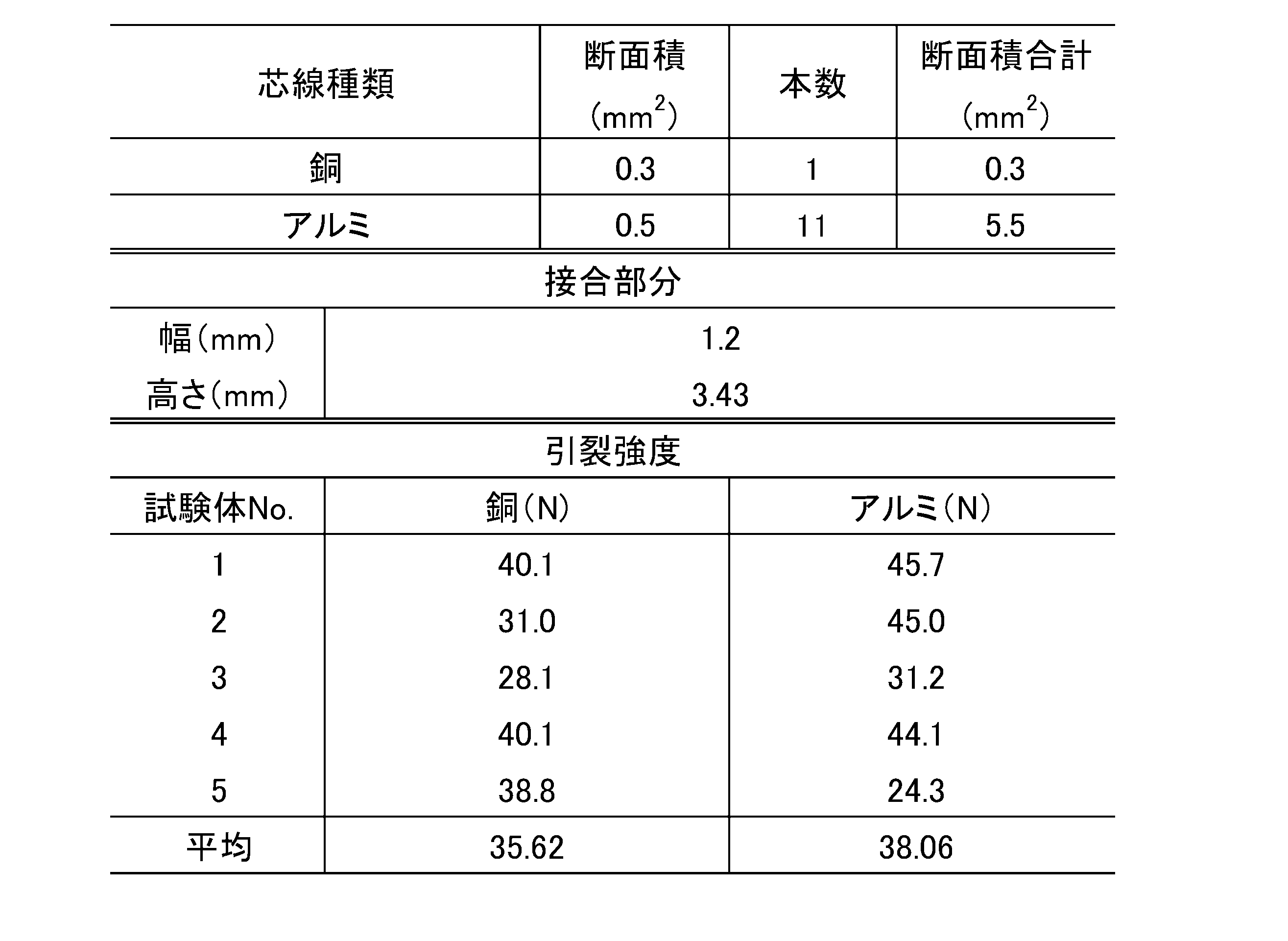
[結果]
表1に示すように、試験例1において、銅電線を引っ張った場合、アルミニウム電線を引っ張った場合のいずれにおいても、高い引裂強度が示され、接合部分において2種の芯線が強固に接合していることが分かった。他の試験例についても同様であった。 [result]
As shown in Table 1, in Test Example 1, when the copper electric wire was pulled or when the aluminum electric wire was pulled, high tear strength was shown, and the two core wires were firmly joined at the joint portion. I found out. The same was true for the other test examples.
1、40、50…ハーネス
10A、51A…第1電線
10B、51B…第2電線
11A、52A…第1芯線
11B、52B…第2芯線
11AE、52AE…第1芯線露出部
11BE、52BE…第2芯線露出部
12A…第1絶縁被覆
12B…第2絶縁被覆
20、41、53…接合部
21、54…第1層
22、55…第2層
30…超音波溶接装置
31…アンビル(受け冶具)
32…溶接ホーン
L…左側面 (他方の対をなす外面)
R…右側面 (他方の対をなす外面)
Up…上面 (一方の対をなす外面、第2当接面)
Ud…下面 (一方の対をなす外面、第1当接面) DESCRIPTION OF SYMBOLS 1, 40, 50 ... Harness 10A, 51A ... 1st electric wire 10B, 51B ... 2nd electric wire 11A, 52A ... 1st core wire 11B, 52B ... 2nd core wire 11AE, 52AE ... 1st core wire exposed part 11BE, 52BE ... 2nd Core wire exposure part 12A ... 1st insulation coating 12B ... 2nd insulation coating 20, 41, 53 ... Joint part 21, 54 ... 1st layer 22, 55 ... 2nd layer 30 ... Ultrasonic welding apparatus 31 ... Anvil (receiving jig)
32 ... Welding horn L ... Left side (the outer surface forming the other pair)
R ... Right side (outer side of the other pair)
Up ... Upper surface (outer surface forming one pair, second contact surface)
Ud: lower surface (one pair of outer surfaces, first contact surface)
10A、51A…第1電線
10B、51B…第2電線
11A、52A…第1芯線
11B、52B…第2芯線
11AE、52AE…第1芯線露出部
11BE、52BE…第2芯線露出部
12A…第1絶縁被覆
12B…第2絶縁被覆
20、41、53…接合部
21、54…第1層
22、55…第2層
30…超音波溶接装置
31…アンビル(受け冶具)
32…溶接ホーン
L…左側面 (他方の対をなす外面)
R…右側面 (他方の対をなす外面)
Up…上面 (一方の対をなす外面、第2当接面)
Ud…下面 (一方の対をなす外面、第1当接面) DESCRIPTION OF
32 ... Welding horn L ... Left side (the outer surface forming the other pair)
R ... Right side (outer side of the other pair)
Up ... Upper surface (outer surface forming one pair, second contact surface)
Ud: lower surface (one pair of outer surfaces, first contact surface)
Claims (5)
- 第1芯線と、前記第1芯線を被覆する第1絶縁被覆とを備え、前記第1芯線が、部分的に前記第1絶縁被覆から露出された第1芯線露出部を有する単数または複数の第1電線と、
前記第1芯線とは異なる材料により構成された第2芯線と、前記第2芯線を被覆する第2絶縁被覆とを備え、前記第2芯線が、部分的に前記第2絶縁被覆から露出された第2芯線露出部を有する単数または複数の第2電線と、
前記第1芯線露出部と前記第2芯線露出部とが溶接された接合部とを備え、
前記第2芯線の総断面積が、前記第1芯線および前記第2芯線の総断面積の合計の3分の1以下であり、
前記接合部が、前記第1電線および前記第2電線の延び方向に沿って延び、互いに対向する2対の外面を有しているとともに、前記2対の外面のうち一方の対をなす外面間の距離が、他方の対をなす外面間の距離よりも長くなっており、
前記接合部において、前記第2芯線露出部が、前記一方の対をなす外面のうち一の外面に隣接して配置されている、電線の接続構造。 The first core wire and a first insulation coating that covers the first core wire, wherein the first core wire has a first core wire exposed portion that is partially exposed from the first insulation coating. One wire,
A second core wire made of a material different from the first core wire; and a second insulating coating that covers the second core wire, wherein the second core wire is partially exposed from the second insulating coating. One or a plurality of second electric wires having a second core wire exposed portion;
The first core wire exposed portion and the second core wire exposed portion are welded to each other;
The total cross-sectional area of the second core wire is not more than one third of the total cross-sectional area of the first core wire and the second core wire;
The joint portion extends along the extending direction of the first electric wire and the second electric wire, and has two pairs of outer surfaces facing each other, and between the outer surfaces forming one pair of the two pairs of outer surfaces. Is longer than the distance between the outer surfaces of the other pair,
In the joint portion, the second core wire exposed portion is disposed adjacent to one outer surface of the outer surfaces forming the one pair, and is an electric wire connection structure. - 前記第1芯線および前記第2芯線のうち一方がアルミニウムまたはアルミニウム合金製である、請求項1に記載の電線の接続構造。 The electric wire connection structure according to claim 1, wherein one of the first core wire and the second core wire is made of aluminum or an aluminum alloy.
- 前記第1芯線および前記第2芯線のうち他方が銅または銅合金製である、請求項2に記載の電線の接続構造。 The electric wire connection structure according to claim 2, wherein the other of the first core wire and the second core wire is made of copper or a copper alloy.
- 前記接合部が、前記第1芯線露出部により構成される第1層と、前記第1層に隣接し、前記第2芯線露出部により構成される第2層とを備える、請求項1~3のいずれか1項に記載の電線の接続構造。 The joint portion includes a first layer constituted by the first core wire exposed portion and a second layer adjacent to the first layer and constituted by the second core wire exposed portion. The electric wire connection structure according to any one of the above.
- 第1芯線と、前記第1芯線を被覆する第1絶縁被覆とを備える単数または複数の第1電線と、
前記第1芯線とは異なる材料により構成された第2芯線と、前記第2芯線を被覆する第2絶縁被覆とを備える単数または複数の第2電線とを接続する方法であって、
前記第2芯線の総断面積が、前記第1芯線および前記第2芯線の総断面積の合計の3分の1以下であり、
前記第1電線および前記第2電線のそれぞれの一部において、前記第1絶縁被覆および前記第2絶縁被覆を皮剥きして前記第1芯線および前記第2芯線を露出させる露出工程と、
溶接ホーンと受け冶具とを備える超音波溶接装置によって、前記第1芯線および前記第2芯線のうち前記露出工程において露出された部分を超音波溶接して接合部を形成する溶接工程とを含み、
前記溶接工程において、
前記第1芯線が前記受け冶具に当接し、前記第2芯線が前記溶接ホーンに当接するようにして溶接を行うとともに、
前記接合部において、前記受け冶具に当接する第1当接面と、前記溶接ホーンに当接する第2当接面との距離が、前記第1当接面および前記第2当接面とは異なる1対の外面間の距離よりも大きくされる、電線の接続方法。 One or a plurality of first electric wires each including a first core wire and a first insulating coating covering the first core wire;
A method of connecting a second core wire made of a material different from the first core wire and a single or a plurality of second electric wires including a second insulating coating covering the second core wire,
The total cross-sectional area of the second core wire is not more than one third of the total cross-sectional area of the first core wire and the second core wire;
In each of the first electric wire and the second electric wire, an exposing step of peeling the first insulating coating and the second insulating coating to expose the first core wire and the second core wire;
A welding step of ultrasonically welding a portion exposed in the exposing step of the first core wire and the second core wire by an ultrasonic welding apparatus including a welding horn and a receiving jig;
In the welding process,
While performing welding so that the first core wire contacts the receiving jig, and the second core wire contacts the welding horn,
In the joint portion, a distance between a first contact surface that contacts the receiving jig and a second contact surface that contacts the welding horn is different from the first contact surface and the second contact surface. A method for connecting electric wires, which is larger than a distance between a pair of outer surfaces.
Priority Applications (4)
| Application Number | Priority Date | Filing Date | Title |
|---|---|---|---|
| DE112019002641.0T DE112019002641T5 (en) | 2018-05-24 | 2019-05-17 | Wire connection structure and wire connection method |
| JP2020521202A JP6901047B2 (en) | 2018-05-24 | 2019-05-17 | Wire connection structure and wire connection method |
| CN201980030287.3A CN112074993B (en) | 2018-05-24 | 2019-05-17 | Wire connection structure and wire connection method |
| US17/054,287 US11462842B2 (en) | 2018-05-24 | 2019-05-17 | Wire connection structure and wire connection method |
Applications Claiming Priority (2)
| Application Number | Priority Date | Filing Date | Title |
|---|---|---|---|
| JP2018-099503 | 2018-05-24 | ||
| JP2018099503 | 2018-05-24 |
Publications (1)
| Publication Number | Publication Date |
|---|---|
| WO2019225492A1 true WO2019225492A1 (en) | 2019-11-28 |
Family
ID=68616720
Family Applications (1)
| Application Number | Title | Priority Date | Filing Date |
|---|---|---|---|
| PCT/JP2019/019629 WO2019225492A1 (en) | 2018-05-24 | 2019-05-17 | Electric wire connection structure and electric wire connection method |
Country Status (5)
| Country | Link |
|---|---|
| US (1) | US11462842B2 (en) |
| JP (1) | JP6901047B2 (en) |
| CN (1) | CN112074993B (en) |
| DE (1) | DE112019002641T5 (en) |
| WO (1) | WO2019225492A1 (en) |
Families Citing this family (3)
| Publication number | Priority date | Publication date | Assignee | Title |
|---|---|---|---|---|
| JP7044958B2 (en) * | 2018-10-25 | 2022-03-31 | 株式会社オートネットワーク技術研究所 | Wire connection structure and wire connection method |
| CN210985000U (en) * | 2019-11-28 | 2020-07-10 | 比亚迪股份有限公司 | Connection structure of aluminium cable and terminal and have its vehicle |
| KR20240033214A (en) * | 2021-07-29 | 2024-03-12 | 슈운크 소노시스템스 게엠바하 | Ultrasonic welding methods and ultrasonic welding parts |
Citations (8)
| Publication number | Priority date | Publication date | Assignee | Title |
|---|---|---|---|---|
| JP2007185706A (en) * | 2006-01-16 | 2007-07-26 | Yazaki Corp | Ultrasonic bonding method and electric wire holding device |
| JP2011014438A (en) * | 2009-07-03 | 2011-01-20 | Hitachi Cable Ltd | Electric wire connection structure, and conductive line for vehicle having the same |
| JP2013004346A (en) * | 2011-06-17 | 2013-01-07 | Yazaki Corp | Inter-wire connection structure and manufacturing method therefor |
| JP2013025997A (en) * | 2011-07-20 | 2013-02-04 | Yazaki Corp | Connecting method of electric wire |
| JP2013235671A (en) * | 2012-05-07 | 2013-11-21 | Auto Network Gijutsu Kenkyusho:Kk | Electric wire set |
| JP2013242991A (en) * | 2012-05-18 | 2013-12-05 | Auto Network Gijutsu Kenkyusho:Kk | Junction structure for electric wires |
| JP2017126520A (en) * | 2016-01-15 | 2017-07-20 | 株式会社オートネットワーク技術研究所 | Wire with terminal and method of manufacturing wire with terminal |
| JP2017168400A (en) * | 2016-03-18 | 2017-09-21 | 株式会社オートネットワーク技術研究所 | Terminal-attached electric cable and method for manufacturing the same |
Family Cites Families (9)
| Publication number | Priority date | Publication date | Assignee | Title |
|---|---|---|---|---|
| JP2002191109A (en) * | 2000-12-19 | 2002-07-05 | Yonezawa Densen Kk | Electric wire connecting structure and electric wire connecting method in wire harness |
| NO317716B1 (en) * | 2002-11-29 | 2004-12-06 | Nexans | Procedure for conductive interconnection of two electrical conductors |
| JP4728592B2 (en) | 2004-05-11 | 2011-07-20 | 古河電気工業株式会社 | Insulated wire connection and insulated wire connection method |
| JP2007149421A (en) * | 2005-11-25 | 2007-06-14 | Yazaki Corp | Ultrasonic joining method, device therefor and electric wire bundle |
| DE102008045751B4 (en) * | 2008-09-04 | 2020-01-30 | Te Connectivity Germany Gmbh | Device and method for compacting welding |
| JP5303259B2 (en) * | 2008-12-24 | 2013-10-02 | 矢崎総業株式会社 | Wire connection method |
| JP5666247B2 (en) * | 2010-11-01 | 2015-02-12 | 矢崎総業株式会社 | Electric wire holding structure and electric wire holding method |
| DE102013107637A1 (en) * | 2013-07-18 | 2015-01-22 | Schunk Sonosystems Gmbh | Method for producing a knot by welding |
| DE102013222938B3 (en) * | 2013-11-11 | 2015-04-30 | Schunk Sonosystems Gmbh | Device for welding electrical conductors |
-
2019
- 2019-05-17 CN CN201980030287.3A patent/CN112074993B/en active Active
- 2019-05-17 JP JP2020521202A patent/JP6901047B2/en active Active
- 2019-05-17 DE DE112019002641.0T patent/DE112019002641T5/en active Pending
- 2019-05-17 US US17/054,287 patent/US11462842B2/en active Active
- 2019-05-17 WO PCT/JP2019/019629 patent/WO2019225492A1/en active Application Filing
Patent Citations (8)
| Publication number | Priority date | Publication date | Assignee | Title |
|---|---|---|---|---|
| JP2007185706A (en) * | 2006-01-16 | 2007-07-26 | Yazaki Corp | Ultrasonic bonding method and electric wire holding device |
| JP2011014438A (en) * | 2009-07-03 | 2011-01-20 | Hitachi Cable Ltd | Electric wire connection structure, and conductive line for vehicle having the same |
| JP2013004346A (en) * | 2011-06-17 | 2013-01-07 | Yazaki Corp | Inter-wire connection structure and manufacturing method therefor |
| JP2013025997A (en) * | 2011-07-20 | 2013-02-04 | Yazaki Corp | Connecting method of electric wire |
| JP2013235671A (en) * | 2012-05-07 | 2013-11-21 | Auto Network Gijutsu Kenkyusho:Kk | Electric wire set |
| JP2013242991A (en) * | 2012-05-18 | 2013-12-05 | Auto Network Gijutsu Kenkyusho:Kk | Junction structure for electric wires |
| JP2017126520A (en) * | 2016-01-15 | 2017-07-20 | 株式会社オートネットワーク技術研究所 | Wire with terminal and method of manufacturing wire with terminal |
| JP2017168400A (en) * | 2016-03-18 | 2017-09-21 | 株式会社オートネットワーク技術研究所 | Terminal-attached electric cable and method for manufacturing the same |
Also Published As
| Publication number | Publication date |
|---|---|
| CN112074993B (en) | 2022-03-01 |
| DE112019002641T5 (en) | 2021-05-06 |
| CN112074993A (en) | 2020-12-11 |
| JP6901047B2 (en) | 2021-07-14 |
| JPWO2019225492A1 (en) | 2021-02-12 |
| US11462842B2 (en) | 2022-10-04 |
| US20210184376A1 (en) | 2021-06-17 |
Similar Documents
| Publication | Publication Date | Title |
|---|---|---|
| JP5235369B2 (en) | Wire harness, method for manufacturing the same, and method for connecting insulated wires | |
| WO2019225492A1 (en) | Electric wire connection structure and electric wire connection method | |
| JP2010044887A (en) | Wire harness and method of manufacturing the same, and method of connecting insulation wire | |
| CN110911928B (en) | Wire bonding method and bonded wire | |
| US20160072199A1 (en) | Terminal, terminal-equipped electrical wire, and method for manufacturing terminal-equipped electrical wire | |
| US9793625B2 (en) | Electric wire with connecting terminal and method for manufacturing such electric wire | |
| US20210399443A1 (en) | Wire connection structure and wire connection method | |
| US10038292B2 (en) | Method for connecting insulated wires | |
| JP6373077B2 (en) | Electric wire with crimp terminal | |
| JP2009202158A (en) | Laser welding method | |
| EP3644443A1 (en) | Wire connection structure | |
| WO2018092350A1 (en) | Twisted wire for wire harness and wire harness | |
| JP6013417B2 (en) | Covered wire joining method | |
| JP6316230B2 (en) | Electric wire with connection terminal and method of manufacturing the electric wire | |
| WO2020080092A1 (en) | Connection structure for electrical wire and method for connecting electrical wire | |
| JP6782104B2 (en) | Branch cable | |
| JP6316229B2 (en) | Electric wire with connection terminal and method of manufacturing the electric wire | |
| WO2019181633A1 (en) | Connection structure of electric wires, and method for producing harness | |
| JP6276820B2 (en) | Covered wire joining method | |
| WO2020080077A1 (en) | Connection structure for plurality of electrical wires | |
| JP2016054036A (en) | Method of joining covered conductors | |
| JP2017103078A (en) | Manufacturing method of connection body for multiple wires, and strand array jig | |
| JP2017059384A (en) | Manufacturing method for terminal electric wire | |
| JP2016001552A (en) | Wire joint structure | |
| JP2001015183A (en) | Wrapped conductive terminal with slip prevention |
Legal Events
| Date | Code | Title | Description |
|---|---|---|---|
| 121 | Ep: the epo has been informed by wipo that ep was designated in this application |
Ref document number: 19806788 Country of ref document: EP Kind code of ref document: A1 |
|
| ENP | Entry into the national phase |
Ref document number: 2020521202 Country of ref document: JP Kind code of ref document: A |
|
| 122 | Ep: pct application non-entry in european phase |
Ref document number: 19806788 Country of ref document: EP Kind code of ref document: A1 |