JP2017126520A - Wire with terminal and method of manufacturing wire with terminal - Google Patents
Wire with terminal and method of manufacturing wire with terminal Download PDFInfo
- Publication number
- JP2017126520A JP2017126520A JP2016006116A JP2016006116A JP2017126520A JP 2017126520 A JP2017126520 A JP 2017126520A JP 2016006116 A JP2016006116 A JP 2016006116A JP 2016006116 A JP2016006116 A JP 2016006116A JP 2017126520 A JP2017126520 A JP 2017126520A
- Authority
- JP
- Japan
- Prior art keywords
- terminal
- electric wire
- wire
- wires
- electric
- Prior art date
- Legal status (The legal status is an assumption and is not a legal conclusion. Google has not performed a legal analysis and makes no representation as to the accuracy of the status listed.)
- Pending
Links
Images


Landscapes
- Manufacturing Of Electrical Connectors (AREA)
- Connections Effected By Soldering, Adhesion, Or Permanent Deformation (AREA)
Abstract
Description
この発明は、端子付電線に関する。 The present invention relates to a terminal-attached electric wire.
複数の電線同士を接続する際に、導体に形成される酸化被膜が導電性を悪化させる恐れがある。この酸化被膜の影響を抑える技術が、例えば、特許文献1に開示されている。 When connecting a plurality of electric wires, an oxide film formed on the conductor may deteriorate conductivity. For example, Patent Document 1 discloses a technique for suppressing the influence of the oxide film.
特許文献1では、複数の電線の端部を集合させた状態で1つのジョイント端子を強く圧着(いわゆる強圧着)して酸化被膜を破壊することによって、酸化被膜の影響を抑えるとされている。 In patent document 1, it is supposed that the influence of an oxide film is suppressed by destroying an oxide film by strongly pressing one joint terminal (so-called strong pressure bonding) in a state where the ends of a plurality of electric wires are gathered.
しかしながら、強圧着のみでは、電線の種類及び端子の形状等によっては、依然として酸化被膜の影響が残ってしまう恐れがある。 However, with strong pressure bonding alone, the effect of the oxide film may still remain depending on the type of electric wire and the shape of the terminal.
そこで、本発明は、複数の電線同士を接続する際の導電性の悪化を抑制することができる技術を提供することを目的とする。 Then, an object of this invention is to provide the technique which can suppress the deterioration of electroconductivity at the time of connecting a some electric wire.
上記課題を解決するため、第1の態様に係る端子付電線は、それぞれ芯線と前記芯線を覆う被覆とを含む複数の電線が1つの端子に接続された端子付電線であって、前記端子は、複数の前記電線に圧着され、前記端子と複数の前記電線の前記芯線とが溶接され、かつ、複数の前記電線の前記芯線同士が溶接されている。 In order to solve the above-described problem, the electric wire with terminal according to the first aspect is an electric wire with terminal in which a plurality of electric wires each including a core wire and a coating covering the core wire are connected to one terminal, The terminals and the core wires of the plurality of electric wires are welded to each other, and the core wires of the plurality of electric wires are welded to each other.
第2の態様に係る端子付電線は、第1の態様に係る端子付電線であって、前記端子は、角筒状に形成されている。 The electric wire with a terminal which concerns on a 2nd aspect is an electric wire with a terminal which concerns on a 1st aspect, Comprising: The said terminal is formed in the rectangular tube shape.
第3の態様に係る端子付電線は、第1又は第2の態様に係る端子付電線であって、前記端子はオープンバレル型に形成され、前記端子の周方向の両端縁部が外側に位置するような形状に圧着されている。 The electric wire with terminal according to the third aspect is the electric wire with terminal according to the first or second aspect, wherein the terminal is formed in an open barrel type, and both end edges in the circumferential direction of the terminal are located outside. It is pressure-bonded to such a shape.
第4の態様に係る端子付電線は、第3の態様に係る端子付電線であって、前記端子は、前記両端縁部のうち一方が他方を圧着方向に支持する形状に圧着されている。 The electric wire with a terminal concerning the 4th mode is an electric wire with a terminal concerning the 3rd mode, and the above-mentioned terminal is crimped to the shape where one side supports the other in the direction of crimping among the above-mentioned both ends.
第5の態様に係る端子付電線は、第1から第4のいずれか1つの態様に係る端子付電線であって、前記端子と前記芯線との溶接部分及び前記芯線同士の溶接部分は、超音波溶接されて形成された超音波接合部を構成している。 The electric wire with a terminal according to the fifth aspect is an electric wire with a terminal according to any one of the first to fourth aspects, wherein a welded portion between the terminal and the core wire and a welded portion between the core wires are super The ultrasonic joining part formed by sonic welding is comprised.
第6の態様に係る端子付電線は、第1から第5のいずれか1つの態様に係る端子付電線であって、複数の前記電線は、前記芯線の硬さの異なる第1の電線と第2の電線とを含む。 A terminal-attached electric wire according to a sixth aspect is a terminal-attached electric wire according to any one of the first to fifth aspects, wherein the plurality of electric wires are different from the first electric wire having a different hardness of the core wire. 2 electric wires.
第7の態様に係る端子付電線の製造方法は、複数の電線が1つの端子に接続された端子付電線の製造方法であって、(a)前記端子を複数の前記電線に圧着する工程と、(b)前記端子と複数の前記電線とを溶接すると共に複数の前記電線同士を溶接する工程と、を備える。 The manufacturing method of the electric wire with a terminal which concerns on a 7th aspect is a manufacturing method of the electric wire with a terminal by which the some electric wire was connected to one terminal, (a) The process of crimping | bonding the said terminal to the said some electric wire, (B) welding the terminals and the plurality of electric wires and welding the plurality of electric wires together.
第8の態様に係る端子付電線の製造方法は、第7の態様に係る端子付電線の製造方法であって、前記工程(a)において、前記端子は、外形が角形状となるように圧着され、前記工程(b)において、外形が角形状とされた前記端子に対して超音波溶接を行う。 The manufacturing method of the electric wire with a terminal which concerns on an 8th aspect is a manufacturing method of the electric wire with a terminal which concerns on a 7th aspect, Comprising: In the said process (a), the said terminal is crimped | bonded so that an external shape may become square shape. Then, in the step (b), ultrasonic welding is performed on the terminal whose outer shape is a square shape.
第9の態様に係る端子付電線の製造方法は、第7又は第8の態様に係る端子付電線の製造方法であって、前記工程(a)において、オープンバレル型に形成された前記端子を、前記端子の周方向の両端縁部が外側に位置するように圧着する。 The manufacturing method of the electric wire with a terminal which concerns on a 9th aspect is a manufacturing method of the electric wire with a terminal which concerns on the 7th or 8th aspect, Comprising: In the said process (a), the said terminal formed in the open barrel type | mold is used. The terminal is crimped so that both end edges in the circumferential direction are located outside.
第10の態様に係る端子付電線の製造方法は、第9の態様に係る端子付電線の製造方法であって、前記工程(a)において、前記両端縁部のうち一方が他方を圧着方向に支持する姿勢で前記端子を圧着する。 The manufacturing method of the electric wire with a terminal which concerns on a 10th aspect is a manufacturing method of the electric wire with a terminal which concerns on a 9th aspect, Comprising: In the said process (a), one is the other in the crimping | compression-bonding direction among the said both-ends edge parts. The terminal is crimped in a supporting posture.
第1から第6の態様によると、圧着時及び溶接時にそれぞれ電線に形成された酸化被膜を破壊することができる。これにより、酸化被膜の影響を抑えることができることによって、複数の電線同士を接続する際の導電性の悪化を抑制することができる。 According to the first to sixth aspects, it is possible to break the oxide film formed on the electric wire during crimping and during welding. Thereby, since the influence of an oxide film can be suppressed, the deterioration of the electroconductivity at the time of connecting a some electric wire can be suppressed.
特に、第2の態様によると、端子が角筒状に形成されている。溶接の際には、溶接対象を加圧しつつ溶接することがある。この際、端子が角筒状に形成されていると、加圧方向に垂直な平面で端子を押えることができるため、振動が端子及び芯線に伝わりやすくなる。これにより、各溶接部分において酸化被膜が破壊された状態で溶接されることによって、導電性の悪化を抑制することができる。 In particular, according to the second aspect, the terminal is formed in a rectangular tube shape. During welding, welding may be performed while pressurizing the object to be welded. At this time, if the terminal is formed in a rectangular tube shape, the terminal can be pressed on a plane perpendicular to the pressurizing direction, so that vibration is easily transmitted to the terminal and the core wire. Thereby, the deterioration of electroconductivity can be suppressed by welding in the state in which the oxide film was destroyed in each welding part.
特に、第3の態様によると、端子がオープンバレル型に形成されているため、電線が複数の素線を含む場合でも、端子内に電線を配設する際に、素線がばらけたり折れ曲がったりすることを抑制することができる。また、端子の周方向の両端縁部が外側に露出するような形状に圧着されているため、オープンバレル型の端子を強く圧着した場合でも、端子の両端縁部が導体に食い込みにくくなり、導体が損傷することを抑えることができる。これにより、導電性の悪化を抑制することができる。 In particular, according to the third aspect, since the terminal is formed in an open barrel shape, even when the electric wire includes a plurality of strands, the strands are scattered or bent when the wires are arranged in the terminals. Can be suppressed. In addition, since both end edges in the circumferential direction of the terminal are crimped in such a way that they are exposed to the outside, even when an open barrel type terminal is strongly crimped, both end edges of the terminal are less likely to bite into the conductor. Can be prevented from being damaged. Thereby, deterioration of conductivity can be suppressed.
特に、第4の態様によると、オープンバレル型の端子を強く圧着した場合でも、端子の両端縁部が導体に食い込みにくくなり、導体が損傷することを抑えることができる。これにより、導電性の悪化を抑制することができる。 In particular, according to the fourth aspect, even when an open barrel type terminal is strongly pressure-bonded, both end edges of the terminal are less likely to bite into the conductor, and the conductor can be prevented from being damaged. Thereby, deterioration of conductivity can be suppressed.
特に、第5の態様によると、端子と芯線との溶接部分及び芯線同士の溶接部分を容易に形成することができる。 In particular, according to the 5th aspect, the welding part of a terminal and a core wire and the welding part of core wires can be formed easily.
特に、第6の態様によると、複数の電線がそれぞれ芯線の硬さの異なる第1の電線と第2の電線とを含む。この場合、芯線の配列状態によっては、圧着時に均等に力が伝わりにくいため、圧着のみでは、酸化被膜を破壊しきれない恐れがある。このような場合でも、圧着と共に溶接を施すことによって導電性の悪化を抑制することができる。 In particular, according to the sixth aspect, each of the plurality of electric wires includes a first electric wire and a second electric wire having different core wire hardnesses. In this case, depending on the arrangement state of the core wires, it is difficult for force to be transmitted evenly at the time of crimping. Even in such a case, the deterioration of conductivity can be suppressed by performing welding together with the pressure bonding.
第7から第10の態様によると、圧着時及び溶接時にそれぞれ酸化被膜を破壊することができる。これにより、酸化被膜の影響を抑えることができることによって、複数の電線同士を接続する際の導電性の悪化を抑制することができる。 According to the seventh to tenth aspects, the oxide film can be destroyed at the time of pressure bonding and welding. Thereby, since the influence of an oxide film can be suppressed, the deterioration of the electroconductivity at the time of connecting a some electric wire can be suppressed.
特に、第8の態様によると、外形が角形状とされた端子に対して超音波溶接を施すため、溶接時に加圧する方向に垂直な平面で端子を押えることができるため、振動が端子及び芯線に伝わりやすくなる。これにより、各溶接部分において酸化被膜が破壊された状態で溶接されることによって、導電性の悪化を抑制することができる。 In particular, according to the eighth aspect, since ultrasonic welding is performed on a terminal whose outer shape is a square shape, the terminal can be pressed in a plane perpendicular to the direction of pressurization during welding. It becomes easy to be transmitted to. Thereby, the deterioration of electroconductivity can be suppressed by welding in the state in which the oxide film was destroyed in each welding part.
特に、第9の態様によると、端子がオープンバレル型に形成されているため、電線が複数の素線からなる場合でも、端子内に電線を配設する際に、素線がばらけたり折れ曲がったりすること抑制することができる。また、端子の周方向の両端縁部が外側に露出するような形状に圧着されているため、オープンバレル型の端子を強く圧着した場合でも、端子の両端縁部が導体に食い込みにくくなり、導体が損傷することを抑えることができる。これにより、導電性の悪化を抑制することができる。 In particular, according to the ninth aspect, since the terminal is formed in an open barrel type, even when the electric wire is composed of a plurality of strands, the strands are scattered or bent when the wires are arranged in the terminals. Can be suppressed. In addition, since both end edges in the circumferential direction of the terminal are crimped in such a way that they are exposed to the outside, even when an open barrel type terminal is strongly crimped, both end edges of the terminal are less likely to bite into the conductor. Can be prevented from being damaged. Thereby, deterioration of conductivity can be suppressed.
特に、第10の態様によると、オープンバレル型の端子を強く圧着した場合でも、端子の両端縁部が導体に食い込みにくくなり、導体が損傷することを抑えることができる。これにより、導電性の悪化を抑制することができる。 In particular, according to the tenth aspect, even when an open barrel type terminal is strongly pressure-bonded, both edge portions of the terminal are less likely to bite into the conductor, and damage to the conductor can be suppressed. Thereby, deterioration of conductivity can be suppressed.
{第1実施形態}
以下、第1実施形態に係る端子付電線について説明する。図1は、第1実施形態に係る端子付電線10を示す概略平面図である。図2は、第1実施形態に係る端子付電線10を示す概略断面図である。
{First embodiment}
Hereinafter, the electric wire with a terminal concerning a 1st embodiment is explained. FIG. 1 is a schematic plan view showing a terminal-attached
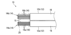
端子付電線10は、複数の電線12が1つの端子20に接続されて形成されている。ここでは、圧着及び溶接の両方を用いて電線12が端子20に接続されている。
The terminal-attached
電線12は、芯線14と芯線14の周囲に形成され、芯線14を覆う被覆18とを含む。芯線14は、銅、銅合金、アルミニウム、アルミニウム合金等の導電性材料によって線状に形成されている。ここでは、芯線14は、複数の素線16が撚り合わされた構成とされている。もっとも、芯線14は、単線によって構成されていてもよい。被覆18は、絶縁性樹脂材料が押出装置等により芯線14の周りに押し出されることによって形成される。この電線12の先端部には、芯線14が露出しており、所定長の露出芯線部15が形成されている。
The
ここでは、複数の電線12は、芯線14の硬さの異なる第1の電線12aと第2の電線12bとを含む。ここでは、第1の電線12aの芯線14aは、銅又は銅合金を材料として形成されており、第2の電線12bの芯線14bは、アルミニウム又はアルミニウム合金を材料として形成されているものとして説明する。つまり、ここでは、第1の電線12aとして銅電線12aが用いられ、第2の電線12bとしてアルミニウム電線12bが用いられる。この場合、第1の電線12aの芯線14aは、第2の電線12bの芯線14bよりも硬い。ここでは、1本の銅電線12aと、1本のアルミニウム電線12bが1つの端子20に接続されているものとして説明する。もっとも、銅電線12a及びアルミニウム電線12bのうち少なくとも一方が複数本含まれていることも考えられる。
Here, the some
なお、ここでは銅電線12aとアルミニウム電線12bとは、スプライス接続されている。この際、アルミニウムは銅に比べて電気抵抗率が大きい。このため、アルミニウム電線12bの電気抵抗と銅電線12aの電気抵抗とを同じにするためにアルミニウム電線12bの芯線14bの断面積は銅電線12aの芯線14aの断面積よりも大きく設定されている。
Here, the
端子20は、複数の電線12に圧着されている。端子20は、例えば、銅又は銅合金等によって形成された板材をプレス加工等することによって形成された部材である。端子20の表面には、錫メッキ等が施されていてもよい。ここでは、端子20として、オープンバレル型の端子20が用いられている。
The terminal 20 is crimped to the plurality of
端子20は、芯線圧着部22を含む。芯線圧着部22は、圧着前に開いた形状、いわゆるオープンバレル型に形成されている。端子20は、角筒状に圧着されている。具体的には、圧着前の芯線圧着部22は、底部24の両側部に一対の圧着片26、27が延出形成された構成とされている。従って、一対の圧着片26、27の先端縁部26a、27aがそれぞれ端子20の周方向の端縁部をなしている。底部24は、平面状に形成されている。一方の圧着片26は他方の圧着片27よりも突出寸法が大きくなるように形成されている。底部24上に露出芯線部15が配設された状態で、圧着片26、27が露出芯線部15にかしめられる。ここでは、一方の圧着片26の先端縁部26aが他方の圧着片27の先端縁部27aに接するように圧着される。従って、一対の圧着片26、27の先端縁部26a、27a(端子20の周方向の両端縁部)が外側に位置するような形状に圧着されている。これにより、圧着片26、27の先端縁部26a、27aが芯線14に食い込むことが抑制され、素線が断線することが抑制されている。
The terminal 20 includes a core
端子20は、一方の圧着片26の先端縁部26aが他方の圧着片27の先端縁部27aに圧着方向に支持される形状に圧着されている。ここで、圧着方向とは、後述する端子圧着装置50における上型52の移動方向であり、ここでは、底部24に直交する方向である。これにより、圧着片26、27の先端縁部26a、27aが芯線14に食い込むことが抑制されている。
The terminal 20 is crimped to a shape in which the
端子20との接続前の芯線14表面には酸化被膜が形成される場合がある。当該酸化被膜が接続部分に介在した場合、導電性が低下する場合がある。このため、端子付電線10において安定した導電性を確保するために端子20との接続時に当該酸化被膜を破壊することが好ましい。この際、特にアルミニウムは化学親和力が大きいため、アルミニウム電線12bの芯線14b表面に形成される酸化被膜は強固なものとなりやすい。従って、圧着のみで、酸化被膜(特に、アルミニウムの酸化被膜)を破壊するためには、アルミニウム電線12bの各素線16bに一定以上の力が加えられることが望まれる。
An oxide film may be formed on the surface of the
しかしながら、上述したような銅電線12aとアルミニウム電線12bとの硬さの違い及び断面積の違い等から、端子20圧着時の芯線14(素線16)の配列等によっては、同じ圧着方法で圧着した場合でも、アルミニウム電線12bの各素線16bに加えられる力にばらつきが大きくなる恐れがある。この場合、アルミニウム電線12bの素線16bに一定以上の力が加えられず、当該素線16bの酸化被膜を破壊しきれない恐れが生じる。酸化被膜を破壊しきれないこのような端子付電線10は、十分な導電性を得られない恐れがある。
However, due to the difference in hardness and cross-sectional area between the
このように、端子と芯線とが圧着のみで接続される場合、製品ごとに品質に大きなばらつきが生じ、一部が不良となってしまう恐れがある。このような事態を回避するため、ここでは端子付電線10において、端子20圧着後に溶接を施している。ここでは端子20と複数の電線12の芯線14とが溶接されている。また、複数の電線12の芯線14同士が溶接されている。より詳細には、芯線14a同士が溶接され、芯線14b同士が溶接され、さらに芯線14aと芯線14bとが溶接されている。ここでは端子20と芯線14との溶接部分及び芯線14同士の溶接部分は、超音波溶接されて形成された超音波接合部30を構成している。即ち、ここでは、端子20の内部が一体になるように超音波溶接されて、超音波接合部30とされている。超音波溶接については、以下の製造方法で詳述する。もっとも、溶接方法としては、超音波溶接に限られるものではなく、抵抗溶接等ほかの溶接方法が採用されてもよい。
Thus, when a terminal and a core wire are connected only by pressure bonding, there is a possibility that quality varies greatly from product to product and a part of the product becomes defective. In order to avoid such a situation, here, the terminal-attached
<製造方法>
第1実施形態に係る端子付電線10の製造方法について図3及び図4を参照しつつ説明する。図3及び図4は、第1実施形態に係る端子付電線10を製造する様子を示す説明図である。
<Manufacturing method>
The manufacturing method of the
まずは、図3に示すように、オープンバレル型に形成された端子20において開口を通じて内部に芯線14を配設する。この際、素線16の配列は、電線12ごとにまとめられたものとされているが、このことは必須ではない。2つの電線12の各素線16が散在するように混ぜられていてもよい。
First, as shown in FIG. 3, the
端子20内に芯線14が配設されたら、端子20を複数の電線12に圧着する。端子20の圧着は、例えば、接近及び離間移動可能に対向配置された上型52(クリンパとも言う)と下型54(アンビルとも言う)とを備える端子圧着装置50によってなされる。上述したように、上型52の移動方向を圧着方向と呼ぶことがある。この際、ここでは上型52及び下型54の対向する面53、55が、それぞれ凹面状に形成されている。また、各面53、55の底面53a、55aが平面状に形成されている。これにより、端子20が、底面53a、55aとの間に挟まれるように圧着され、その外形が角形状となる。なお、上型52の面53のうち突出寸法の大きい圧着片26の上方に位置する部分は、曲面状に形成され、圧着片26を底面53aに向けてガイド可能なガイド面53bとされることが考えられる。
When the
より詳細には、下型54の面55の底面55a上に端子20及び電線12が載置された状態で上型52を下型54に向けて接近移動させていく。すると、突出寸法の大きい圧着片26の先端が上型52の面53によって徐々に他方の圧着片27の先端に近づいていき、やがて接するようになる。この状態でさらに上型52を下型54に近づけていき、端子20を圧縮することで端子20が複数の電線12に圧着された状態となる。この際、端子20の周方向の両端縁部26a、27aが外側に位置する。特にここでは、両端縁部26a、27aのうち一方26aが他方27aに圧着方向に支持される。これにより、端子20の周方向の両端縁部が電線12に食い込むことが抑制される。
More specifically, the
なお、端子20のうち四隅の角部は、若干丸められていることも考えられえる。特に、端子20のうち上型52のガイド面53bに当接する角部は、ガイド面53bの形状に応じて若干丸められていることが考えられる。
Note that the corners of the four corners of the terminal 20 may be slightly rounded. In particular, it is conceivable that the corner of the terminal 20 that contacts the
端子20の圧着が完了したら、溶接工程に移る。ここでは、端子20が複数の電線12に圧着されたワークWにおいて、複数の電線12の芯線14同士を溶接すると共に、端子20と複数の電線12の芯線14とを溶接する。ここでは、図4に示すように、外形が角形状とされた端子20に対して超音波溶接装置60を用いて超音波溶接を行う。
If the crimping | compression-bonding of the terminal 20 is completed, it will move to a welding process. Here, in the workpiece W in which the
ここで超音波溶接装置60について説明する。超音波溶接装置60は、ソノトロード62とアンビルプレート64とグライディングジョー66とアンビル68とを備える。
Here, the
ソノトロード62はワークWを載置可能に形成される共に載置されたワークWに対して超音波に起因する振動を付与する。ソノトロード62において、ワークWが載置される載置面62aは平面状に形成されている。ソノトロード62は、載置面62aに平行な方向に振動する。
The
アンビルプレート64は、ソノトロード62の側方に配置され、ワークWの一方側面を押えている。アンビルプレート64のうちワークWを向く押え面64aは、載置面62aと直交する平面状に形成されている。
The
グライディングジョー66は、ソノトロード62の上方に配置されている。グライディングジョー66は、アンビルプレート64とは反対側に配置され、載置面62aに載せられたワークWの他方側面を押えている。グライディングジョー66のうちワークWを向く押え面66aは、載置面62aと直交する平面状に形成されている。つまり、アンビルプレート64の押え面64aとグライディングジョー66の押え面66aとは、共に載置面62aに直交し、相互に平行な平面状に形成されている。
The gliding
アンビル68は、ソノトロード62及びアンビルプレート64の上方に配置されている。アンビル68のうちソノトロード62の載置面62aに対向する押え面68aは、載置面62aと平行な平面状に形成されている。
The
次に、上記超音波溶接装置60を用いた溶接方法について説明する。
Next, a welding method using the
まずは、複数の電線12に端子20が圧着されたワークWを、ソノトロード62の載置面62a上に載置する。
First, the workpiece W in which the
ワークWが載置面62aに載置されたら、グライディングジョー66とアンビルプレート64とで、ワークWの両側面を挟持する。このようにグライディングジョー66及びアンビルプレート64によってワークWの両側面を挟持することにより、当該ワークWの水平方向への移動が規制される。なお、グライディングジョー66及びアンビルプレート64によって、ワークWの両側面を加圧しつつ挟持してもよい。
When the workpiece W is placed on the
ワークWの両側面がグライディングジョー66とアンビルプレート64とによって挟持されたら、ソノトロード62とアンビル68とで、ワークWの上面及び下面を加圧しつつ挟持する。
When both side surfaces of the workpiece W are clamped by the gliding
なお、ワークWに対する加圧量は、超音波溶接にかかるワークWの大きさ、材質及び目標とする溶接度合い等によって適宜設定される。この際、圧着工程では、端子20を弱く圧着しつつ超音波溶接工程における溶接前の加圧工程で端子20を強く圧着するようにしてもよい。 Note that the amount of pressure applied to the workpiece W is appropriately set depending on the size, material, and target welding degree of the workpiece W for ultrasonic welding. At this time, in the crimping process, the terminal 20 may be strongly crimped in the pressurizing process before welding in the ultrasonic welding process while the terminal 20 is crimped weakly.
ワークWに対する加圧が完了したら、最後に、ワークWに超音波振動を付与して溶接する超音波溶接工程を行う。即ち、超音波溶接装置60の各部材でワークWを加圧しながら、ソノトロード62を超音波振動させる。これにより、ワークWを溶接することができる。より詳細には、端子20と芯線14とを溶接することができると共に芯線14同士を溶接することができる。この際、端子20が四角形状に形成されているため、加圧方向に垂直な平面で端子20を押えることができる。これにより、振動が端子20及び芯線14に伝わりやすくなる。ワークWの溶接が完了することで、端子付電線10が完成となる。
When the pressurization to the workpiece W is completed, finally, an ultrasonic welding process is performed in which ultrasonic vibration is applied to the workpiece W for welding. That is, the
このような端子付電線10及びその製造方法によると、圧着時及び溶接時にそれぞれ電線12の芯線14に形成された酸化被膜を破壊することができる。これにより、酸化被膜の影響を抑えることができることによって、複数の電線12同士を接続する際の導電性の悪化を抑制することができる。
According to the terminal-attached
また、溶接の際には、溶接対象を加圧しつつ溶接することがある。この際、端子20が四角筒状に形成されていると、加圧方向に垂直な平面で端子20を押えることができるため、振動が端子20及び芯線14に伝わりやすくなる。これにより、各溶接部分において酸化被膜が破壊された状態で溶接されることによって、導電性の悪化を抑制することができる。
Further, during welding, welding may be performed while pressurizing the object to be welded. At this time, if the terminal 20 is formed in a rectangular tube shape, the terminal 20 can be pressed in a plane perpendicular to the pressurizing direction, so that vibration is easily transmitted to the terminal 20 and the
端子20がオープンバレル型に形成されているため、電線12が複数の素線16を含む場合でも、端子20内に電線12を配設する際に、素線16がばらけたり折れ曲がったりすること抑制することができる。また、端子20の周方向の両端縁部26a、27aが外側に露出するような形状に圧着されているため、オープンバレル型の端子20を強く圧着した場合でも、端子20の両端縁部26a、27aが導体に食い込みにくくなり、導体が損傷することを抑えることができる。これにより、導電性の悪化を抑制することができる。特に、端子20の周方向の一方端縁部27aが他方端縁部26aを圧着方向に支持しているため、オープンバレル型の端子20を強く圧着した場合でも、端子20の両端縁部26a、27aが導体に食い込みにくくなり、導体が損傷することを抑えることができる。これにより、導電性の悪化を抑制することができる。
Since the terminal 20 is formed in an open barrel shape, even when the
また、超音波溶接を採用しているため、端子20と芯線14との溶接部分及び芯線14同士の溶接部分を容易に形成することができる。
Moreover, since ultrasonic welding is employed, a welded portion between the terminal 20 and the
複数の電線12がそれぞれ芯線14の硬さの異なる第1の電線12aと第2の電線12bとを含む。この場合、芯線14の配列状態によっては、圧着時に均等に力が伝わりにくいため、圧着のみでは酸化被膜を破壊しきれない恐れがある。このような場合でも、圧着と共に溶接を施すことによって導電性の悪化を抑制することができる。
Each of the plurality of
{第2実施形態}
次に、第2実施形態に係る端子付電線について説明する。図5は、第2実施形態に係る端子付電線110を示す概略断面図である。図6は、第2実施形態に係る端子付電線110を製造する様子を示す説明図である。なお、本実施の形態の説明において、これまでに説明したものと同様構成要素については同一符号を付してその説明を省略する。
{Second Embodiment}
Next, the electric wire with a terminal concerning a 2nd embodiment is explained. FIG. 5 is a schematic cross-sectional view showing a terminal-attached
第2実施形態に係る端子付電線110においては、端子120の形状が第1実施形態に係る端子20の形状とは異なる。
In the electric wire with
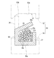
ここでは、端子120は、一対の圧着片126、127が同程度の突出寸法を有するように形成され、周方向両端縁部126a、126bが端子120の幅方向中間部分で接するように圧着されている。このような端子120の圧着前の状態は、図6に示すように、一対の圧着片126、127が共に外側に開いた形状に形成されている。そして、一対の圧着片126、127は、その先端縁部126a、127aが閉じられつつ先端縁部126a、127a同士が突きあうような形状に圧着される。
Here, the terminal 120 is formed such that the pair of crimping
このような端子120を採用して端子付電線110を製造した場合でも、端子の周方向一方端縁部が他方端縁部を圧着方向に支持することによる効果以外の効果については、第1実施形態に係る端子付電線10及びその製造方法と同様の効果を得ることができる。
Even when the terminal-equipped
{第3実施形態}
次に、第3実施形態に係る端子付電線について説明する。図7は、第3実施形態に係る端子付電線210を示す概略断面図である。図8及び図9は、第3実施形態に係る端子付電線210を製造する様子を示す説明図である。なお、本実施の形態の説明において、これまでに説明したものと同様構成要素については同一符号を付してその説明を省略する。
{Third embodiment}
Next, the electric wire with a terminal concerning a 3rd embodiment is explained. FIG. 7 is a schematic cross-sectional view showing a terminal-attached
第3実施形態に係る端子付電線210においては、端子220の形状が第1実施形態に係る端子20の形状とは異なる。
In the electric wire with
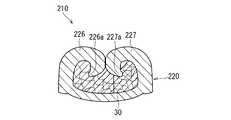
ここでは、底部224がV字状に形成されている。また、一対の圧着片226、227が同程度の突出寸法を有するように形成され、周方向両端縁部226a、227aが端子220の内側に位置する態様で徐々に曲るように圧着されている。このような端子220の圧着前の状態は、図7に示すように、一対の圧着片226、227が共に外側に開いた形状に形成されている。そして、一対の圧着片226、227は、その先端縁部226a、227aが近接しながら端子220の内側に入りこむように圧着される。
Here, the bottom 224 is formed in a V shape. Further, the pair of crimping
このような端子220を採用して端子付電線210を製造した場合でも、端子が角筒状に形成されていること及びそれに付随して端子の周方向一方端縁部が他方端縁部を圧着方向に支持することによる効果以外の効果については、第1実施形態に係る端子付電線10及びその製造方法と同様の効果を得ることができる。
Even when the terminal-equipped
{変形例}
各実施形態において、電線12が芯線14の硬さの異なる第1の電線12aと第2の電線12bとを含むものとして説明したが、このことは必須ではない。端子付電線を構成する芯線の種類は、1種類であってもよいし、3種類以上であってもよい。例えば、複数のアルミニウム電線のみが1つの端子に圧着されていてもよい。
{Modifications}
In each embodiment, although the
また、当該端子付電線10において、端子20が接続される部分は、スプライス接続された部分であるものとして説明したが、このことは必須ではない。例えば、端子付電線において端子が接続された部分は、複数の電線が相手側接続部を含む1つの端子に圧着されるものであってもよい。この場合、相手側接続部の形状としては、例えば、芯線圧着部の底部から延出する板状部分にボルト挿通用の孔が形成された形状が考えられる。このような端子は、例えば、アース端子として用いられる。さらに端子は、芯線圧着部に加えて、被覆圧着部を含むことが考えられる。被覆圧着部は、芯線圧着部に対して一方側(相手側接続部が設けられる場合は、相手側接続部とは反対側)に形成され、底部の両側部に一対の圧着片が延出形成された構成とされることが考えられる。そして、底部上に被覆の端部を配設した状態で、一対の圧着片が被覆にかしめられる。
Moreover, in the said
なお、上記各実施形態及び各変形例で説明した各構成は、相互に矛盾しない限り適宜組み合わせることができる。 In addition, each structure demonstrated by said each embodiment and each modification can be suitably combined unless it mutually contradicts.
以上のようにこの発明は詳細に説明されたが、上記した説明は、すべての局面において、例示であって、この発明がそれに限定されるものではない。例示されていない無数の変形例が、この発明の範囲から外れることなく想定され得るものと解される。 As described above, the present invention has been described in detail. However, the above description is illustrative in all aspects, and the present invention is not limited thereto. It is understood that countless variations that are not illustrated can be envisaged without departing from the scope of the present invention.
10 端子付電線
12 電線
14 芯線
15 露出芯線部
16 素線
18 被覆
20 端子
22 芯線圧着部
24 底部
26 圧着片
30 超音波接合部
50 端子圧着装置
60 超音波溶接装置
DESCRIPTION OF
Claims (10)
前記端子は、複数の前記電線に圧着され、
前記端子と複数の前記電線の前記芯線とが溶接され、かつ、複数の前記電線の前記芯線同士が溶接されている、端子付電線。 A plurality of electric wires each including a core wire and a coating covering the core wire are connected to one terminal,
The terminal is crimped to a plurality of the electric wires,
An electric wire with a terminal, wherein the terminal and the core wires of the plurality of electric wires are welded, and the core wires of the plurality of electric wires are welded to each other.
前記端子は、角筒状に形成されている、端子付電線。 It is an electric wire with a terminal according to claim 1,
The said terminal is an electric wire with a terminal formed in the shape of a square tube.
前記端子はオープンバレル型に形成され、前記端子の周方向の両端縁部が外側に位置するような形状に圧着されている、端子付電線。 It is an electric wire with a terminal according to claim 1 or claim 2,
The electric wire with a terminal, wherein the terminal is formed in an open barrel shape, and is crimped in such a shape that both end edges in the circumferential direction of the terminal are located outside.
前記端子は、前記両端縁部のうち一方が他方を圧着方向に支持する形状に圧着されている、端子付電線。 It is an electric wire with a terminal according to claim 3,
The said terminal is an electric wire with a terminal currently crimped | bonded by the shape which one side supports the other in the crimping | compression-bonding direction among the said both ends edge part.
前記端子と前記芯線との溶接部分及び前記芯線同士の溶接部分は、超音波溶接されて形成された超音波接合部を構成している、端子付電線。 It is an electric wire with a terminal given in any 1 paragraph of Claims 1-4,
The welded portion of the terminal and the core wire and the welded portion of the core wires are terminal-attached electric wires that constitute an ultrasonic joint formed by ultrasonic welding.
複数の前記電線は、前記芯線の硬さの異なる第1の電線と第2の電線とを含む、端子付電線。 It is an electric wire with a terminal given in any 1 paragraph of Claims 1-5,
The plurality of electric wires are a terminal-attached electric wire including a first electric wire and a second electric wire having different hardnesses of the core wire.
(a)前記端子を複数の前記電線に圧着する工程と、
(b)前記端子と複数の前記電線とを溶接すると共に複数の前記電線同士を溶接する工程と、
を備える、端子付電線の製造方法。 A method of manufacturing a terminal-attached electric wire in which a plurality of electric wires are connected to one terminal,
(A) a step of crimping the terminals to the plurality of electric wires;
(B) welding the plurality of electric wires while welding the terminal and the plurality of electric wires;
The manufacturing method of the electric wire with a terminal provided with.
前記工程(a)において、前記端子は、外形が角形状となるように圧着され、
前記工程(b)において、外形が角形状とされた前記端子に対して超音波溶接を行う、端子付電線の製造方法。 It is a manufacturing method of the electric wire with a terminal according to claim 7,
In the step (a), the terminal is crimped so that the outer shape is a square shape,
In the step (b), a method for manufacturing a terminal-attached electric wire, wherein ultrasonic welding is performed on the terminal whose outer shape is a square shape.
前記工程(a)において、オープンバレル型に形成された前記端子を、前記端子の周方向の両端縁部が外側に位置するように圧着する、端子付電線の製造方法。 It is a manufacturing method of the electric wire with a terminal according to claim 7 or claim 8,
In the step (a), the terminal formed in an open barrel shape is crimped so that both end edges in the circumferential direction of the terminal are located outside.
前記工程(a)において、前記両端縁部のうち一方が他方を圧着方向に支持する姿勢で前記端子を圧着する、端子付電線の製造方法。 It is a manufacturing method of the electric wire with a terminal according to claim 9,
In the step (a), a method of manufacturing a terminal-attached electric wire, wherein the terminal is crimped in a posture in which one of the end edges supports the other in the crimping direction.
Priority Applications (1)
| Application Number | Priority Date | Filing Date | Title |
|---|---|---|---|
| JP2016006116A JP2017126520A (en) | 2016-01-15 | 2016-01-15 | Wire with terminal and method of manufacturing wire with terminal |
Applications Claiming Priority (1)
| Application Number | Priority Date | Filing Date | Title |
|---|---|---|---|
| JP2016006116A JP2017126520A (en) | 2016-01-15 | 2016-01-15 | Wire with terminal and method of manufacturing wire with terminal |
Publications (1)
| Publication Number | Publication Date |
|---|---|
| JP2017126520A true JP2017126520A (en) | 2017-07-20 |
Family
ID=59365168
Family Applications (1)
| Application Number | Title | Priority Date | Filing Date |
|---|---|---|---|
| JP2016006116A Pending JP2017126520A (en) | 2016-01-15 | 2016-01-15 | Wire with terminal and method of manufacturing wire with terminal |
Country Status (1)
| Country | Link |
|---|---|
| JP (1) | JP2017126520A (en) |
Cited By (3)
| Publication number | Priority date | Publication date | Assignee | Title |
|---|---|---|---|---|
| JP2019096516A (en) * | 2017-11-24 | 2019-06-20 | 矢崎総業株式会社 | Terminal connection method |
| WO2019225492A1 (en) * | 2018-05-24 | 2019-11-28 | 株式会社オートネットワーク技術研究所 | Electric wire connection structure and electric wire connection method |
| JP2020089120A (en) * | 2018-11-28 | 2020-06-04 | 矢崎総業株式会社 | Method and structure of aluminum wire connection |
-
2016
- 2016-01-15 JP JP2016006116A patent/JP2017126520A/en active Pending
Cited By (7)
| Publication number | Priority date | Publication date | Assignee | Title |
|---|---|---|---|---|
| JP2019096516A (en) * | 2017-11-24 | 2019-06-20 | 矢崎総業株式会社 | Terminal connection method |
| US11139592B2 (en) | 2017-11-24 | 2021-10-05 | Yazaki Corporation | Terminal connecting method |
| WO2019225492A1 (en) * | 2018-05-24 | 2019-11-28 | 株式会社オートネットワーク技術研究所 | Electric wire connection structure and electric wire connection method |
| JPWO2019225492A1 (en) * | 2018-05-24 | 2021-02-12 | 株式会社オートネットワーク技術研究所 | Wire connection structure and wire connection method |
| US11462842B2 (en) | 2018-05-24 | 2022-10-04 | Autonetworks Technologies, Ltd. | Wire connection structure and wire connection method |
| JP2020089120A (en) * | 2018-11-28 | 2020-06-04 | 矢崎総業株式会社 | Method and structure of aluminum wire connection |
| JP7244262B2 (en) | 2018-11-28 | 2023-03-22 | 矢崎総業株式会社 | Aluminum wire connection method and aluminum wire connection structure |
Similar Documents
| Publication | Publication Date | Title |
|---|---|---|
| JP5428789B2 (en) | Electric wire with terminal fitting and method of manufacturing electric wire with terminal fitting | |
| WO2011126115A1 (en) | Electric wire connection method and wire harness | |
| JP2014211953A (en) | Connection method, connection device of wire | |
| JP5400676B2 (en) | Ultrasonic welding method | |
| JP6574736B2 (en) | Manufacturing method of electric wire with terminal | |
| JP2013246886A (en) | Electric wire with terminal, method of manufacturing the same, and jig | |
| JP6574795B2 (en) | Manufacturing method of electric wire with terminal | |
| US10971878B2 (en) | Method for manufacturing terminal-equipped electrical wire, terminal-equipped electrical wire, and ultrasonic welding device | |
| JP2020013633A (en) | Terminal-equipped wire and manufacturing method thereof | |
| JP2020047422A (en) | Bonding method for terminal-equipped electric wire and terminal-equipped bonding electric wire | |
| WO2015025695A1 (en) | Conduction path and electric wire | |
| JP2017126520A (en) | Wire with terminal and method of manufacturing wire with terminal | |
| JP6220559B2 (en) | Electric wire connection method and connection device | |
| JP2022000861A (en) | Terminal equipped electric wire, and manufacturing method of terminal equipped electric wire | |
| US11654505B2 (en) | Method of manufacturing terminal-equipped electric wire and method of damping electric wire | |
| JP2014029884A (en) | Electric wire with terminal fitting, and method for manufacturing electric wire with terminal fitting | |
| JP2011090804A (en) | Electric wire with terminal fitting and method of manufacturing the same | |
| JP2003217784A (en) | Terminal connecting method | |
| JP2017168400A (en) | Terminal-attached electric cable and method for manufacturing the same | |
| JP5474424B2 (en) | Ultrasonic welding method and ultrasonic welding apparatus | |
| JP2013137879A (en) | Electric wire with terminal and manufacturing method of the same | |
| JP2022136634A (en) | Bonding structure for conductors and ultrasonic bonding method for conductors | |
| JP2020202687A (en) | Wire connection structure | |
| JP2022040491A (en) | Pressure welding structure, and electric wire with terminal and manufacturing method thereof | |
| JP2020004649A (en) | Terminal-equipped wire and manufacturing method thereof |