WO2019225367A1 - 情報処理装置、制御装置、移行方法及びプログラム - Google Patents
情報処理装置、制御装置、移行方法及びプログラム Download PDFInfo
- Publication number
- WO2019225367A1 WO2019225367A1 PCT/JP2019/018868 JP2019018868W WO2019225367A1 WO 2019225367 A1 WO2019225367 A1 WO 2019225367A1 JP 2019018868 W JP2019018868 W JP 2019018868W WO 2019225367 A1 WO2019225367 A1 WO 2019225367A1
- Authority
- WO
- WIPO (PCT)
- Prior art keywords
- migration
- address
- vnf
- source
- packet
- Prior art date
- Legal status (The legal status is an assumption and is not a legal conclusion. Google has not performed a legal analysis and makes no representation as to the accuracy of the status listed.)
- Ceased
Links
Images



Classifications
-
- H—ELECTRICITY
- H04—ELECTRIC COMMUNICATION TECHNIQUE
- H04L—TRANSMISSION OF DIGITAL INFORMATION, e.g. TELEGRAPHIC COMMUNICATION
- H04L67/00—Network arrangements or protocols for supporting network services or applications
- H04L67/34—Network arrangements or protocols for supporting network services or applications involving the movement of software or configuration parameters
-
- G—PHYSICS
- G06—COMPUTING OR CALCULATING; COUNTING
- G06F—ELECTRIC DIGITAL DATA PROCESSING
- G06F9/00—Arrangements for program control, e.g. control units
- G06F9/06—Arrangements for program control, e.g. control units using stored programs, i.e. using an internal store of processing equipment to receive or retain programs
- G06F9/44—Arrangements for executing specific programs
- G06F9/455—Emulation; Interpretation; Software simulation, e.g. virtualisation or emulation of application or operating system execution engines
-
- H—ELECTRICITY
- H04—ELECTRIC COMMUNICATION TECHNIQUE
- H04L—TRANSMISSION OF DIGITAL INFORMATION, e.g. TELEGRAPHIC COMMUNICATION
- H04L45/00—Routing or path finding of packets in data switching networks
- H04L45/302—Route determination based on requested QoS
- H04L45/306—Route determination based on the nature of the carried application
-
- H—ELECTRICITY
- H04—ELECTRIC COMMUNICATION TECHNIQUE
- H04L—TRANSMISSION OF DIGITAL INFORMATION, e.g. TELEGRAPHIC COMMUNICATION
- H04L45/00—Routing or path finding of packets in data switching networks
- H04L45/74—Address processing for routing
-
- H—ELECTRICITY
- H04—ELECTRIC COMMUNICATION TECHNIQUE
- H04L—TRANSMISSION OF DIGITAL INFORMATION, e.g. TELEGRAPHIC COMMUNICATION
- H04L61/00—Network arrangements, protocols or services for addressing or naming
- H04L61/50—Address allocation
- H04L61/5084—Providing for device mobility
-
- H—ELECTRICITY
- H04—ELECTRIC COMMUNICATION TECHNIQUE
- H04L—TRANSMISSION OF DIGITAL INFORMATION, e.g. TELEGRAPHIC COMMUNICATION
- H04L67/00—Network arrangements or protocols for supporting network services or applications
- H04L67/01—Protocols
- H04L67/10—Protocols in which an application is distributed across nodes in the network
- H04L67/1095—Replication or mirroring of data, e.g. scheduling or transport for data synchronisation between network nodes
-
- H—ELECTRICITY
- H04—ELECTRIC COMMUNICATION TECHNIQUE
- H04L—TRANSMISSION OF DIGITAL INFORMATION, e.g. TELEGRAPHIC COMMUNICATION
- H04L2101/00—Indexing scheme associated with group H04L61/00
- H04L2101/60—Types of network addresses
- H04L2101/618—Details of network addresses
- H04L2101/622—Layer-2 addresses, e.g. medium access control [MAC] addresses
-
- H—ELECTRICITY
- H04—ELECTRIC COMMUNICATION TECHNIQUE
- H04L—TRANSMISSION OF DIGITAL INFORMATION, e.g. TELEGRAPHIC COMMUNICATION
- H04L61/00—Network arrangements, protocols or services for addressing or naming
- H04L61/09—Mapping addresses
- H04L61/10—Mapping addresses of different types
- H04L61/103—Mapping addresses of different types across network layers, e.g. resolution of network layer into physical layer addresses or address resolution protocol [ARP]
-
- H—ELECTRICITY
- H04—ELECTRIC COMMUNICATION TECHNIQUE
- H04L—TRANSMISSION OF DIGITAL INFORMATION, e.g. TELEGRAPHIC COMMUNICATION
- H04L61/00—Network arrangements, protocols or services for addressing or naming
- H04L61/50—Address allocation
- H04L61/5007—Internet protocol [IP] addresses
-
- H—ELECTRICITY
- H04—ELECTRIC COMMUNICATION TECHNIQUE
- H04L—TRANSMISSION OF DIGITAL INFORMATION, e.g. TELEGRAPHIC COMMUNICATION
- H04L69/00—Network arrangements, protocols or services independent of the application payload and not provided for in the other groups of this subclass
- H04L69/22—Parsing or analysis of headers
Definitions
- the present invention relates to an information processing device, a control device, a migration method, and a program.
- virtual machine technology has been developed that realizes the operating environment of applications realized using physical servers with software.
- the virtual machine is software and operates on a physical platform having an environment in which the virtual machine is operated.
- the virtual machine can be moved to another server in a state in which the virtual machine is operated, and can be continuously operated. This operation is called live migration, and is used as a means for continuing service at the time of server failure or maintenance.
- NFV network function virtualization
- VNF virtual network function
- VNF updates a lot of data used in packet processing. Therefore, when migrating VNF, it is necessary to synchronize these data at the migration source and the migration destination.
- the amount of data to be synchronized is larger than when the virtual machine is used for other purposes. For this reason, if the amount of traffic is large, the data to be synchronized is updated in the migration source VNF during migration, and the time required for migration to synchronize the updated portion is prolonged, and the migration is not completed easily. There are cases.
- Non-Patent Document 1 A method for continuing the packet processing by making it to be performed has been proposed.
- Non-Patent Document 1 updates the route information of the layer 2 switch after VNF synchronization is completed. This is because the transfer destination of the data packet processed by the VNF is changed from the server before migration to the migration destination server.
- the procedure for updating the route information is as follows. (1) First, the destination VNF transmits a broadcast packet with its own layer 2 address attached to the source address field. (2) The layer 2 switch in the network collates the source address field of the arrived broadcast packet with the packet arrival port, and sets the output destination of the packet addressed to the destination VNF. (3) After setting the output destination of the packet addressed to the migration destination VNF, the layer 2 switch transfers the data packet to the VNF operating on the migration destination server.
- the route information update mechanism in Ethernet has a problem that it takes time until all switches update the route information and correctly output packets.
- VNF operates on the migration source server even after the synchronization is completed, and the VNF processes a data packet that has arrived at the migration source server.
- the address of the VNF is attached to the source address of the data packet processed by the migration source VNF.
- the broadcast packet transmitted by the migration destination VNF and the address indicating the transmission source of the packet attached to the data packet transmitted by the migration source VNF are the same (that is, the addresses of the migration source and the migration destination are the same). Duplicate.)
- the route information updated by the broadcast packet transmitted by the migration destination VNF is retransmitted by the data packet transmitted by the migration source VNF. Updated. As a result, the data packet reaches the migration source again, and the data packet does not reach the migration destination.
- the present invention has been made in view of the above points, and it is an object of the present invention to avoid the occurrence of communication fraud when software related to packet processing is transferred to another computer.
- the information processing apparatus outputs the software that processes the packet from the control unit that controls the transfer to or from the other computer and the software that is the transfer source or the transfer destination And an attachment unit for attaching a source address different from the destination or source to the destination packet.
- FIG. 10 is a sequence diagram for explaining an example of a processing procedure related to migration of VNF in the first embodiment. It is a sequence diagram for demonstrating an example of the process sequence regarding the migration of VNF in 2nd Embodiment.
- FIG. 1 is a diagram illustrating a configuration example of a data transfer system 1 according to the first embodiment.
- a plurality of servers 10, such as a server 10a and a server 10b, a controller 20, and one or more packet processing devices 30 are connected via a network N1.
- the network N1 is a layer 2 network including one or more switches 40 (that is, a local area network (LAN)).
- the server 10 is a computer on which a virtual machine operates.
- a process of software hereinafter simply referred to as “VNF process” that realizes a VNF (Virtualized Network Function) function on a virtual machine runs on the server 10.
- the controller 20 is a computer that instructs the server 10 to perform VNF migration (live migration), and performs various notifications accompanying the migration to the packet processing device 30 and the like.
- the controller 20 stores correspondence information between the VNF and the packet processing device 30 that performs packet processing related to the VNF.
- the packet processing device 30 obtains information such as an address from the header of the packet, and performs processing on the packet based on the address.
- the packet processing device 30 may be a device that performs NAPT (Network Address and Port Translation), a device that functions as a firewall, or an SDN (Software Defined Network) switch.
- NAPT Network Address and Port Translation
- SDN Software Defined Network
- packet means a layer 2 packet (frame) unless otherwise specified.
- the address means a layer 2 address (MAC address) unless otherwise specified.
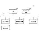
- FIG. 2 is a diagram illustrating a hardware configuration example of the server 10 according to the first embodiment.
- the server 10 in FIG. 2 includes a drive device 100, an auxiliary storage device 102, a memory device 103, a CPU 104, an interface device 105, and the like that are mutually connected by a bus B.
- a program for realizing processing in the server 10 is provided by a recording medium 101 such as a CD-ROM.
- a recording medium 101 such as a CD-ROM.
- the program is installed from the recording medium 101 to the auxiliary storage device 102 via the drive device 100.
- the program need not be installed from the recording medium 101 and may be downloaded from another computer via a network.
- the auxiliary storage device 102 stores the installed program and also stores necessary files and data.
- the memory device 103 reads the program from the auxiliary storage device 102 and stores it when there is an instruction to start the program.
- the CPU 104 executes a function related to the server 10 in accordance with a program stored in the memory device 103.
- the interface device 105 is used as an interface for connecting to a network.
- controller 20 the packet processing device 30, the switch 40, and the like may also have the hardware shown in FIG.
- FIG. 3 is a diagram illustrating a functional configuration example of the server 10 and the controller 20 according to the first embodiment.
- the server 10 includes a migration control unit 11 and an address attachment unit 12. Each of these units is realized by processing that one or more programs installed in the server 10 cause the CPU 104 to execute.
- the migration control unit 11 controls the migration (migration) to the migration destination of the VNF operating on the server 10 or the migration from the migration source of the VNF operating on the other server 10 (the other server 10).
- the address attachment unit 12 attaches (assigns) the address assigned to the VNF to the source address field of the packet output from the VNF operating in the server 10.
- the controller 20 includes a migration instruction unit 21, an address notification unit 22, and the like. Each of these units is realized by processing that one or more programs installed in the controller 20 cause the CPU of the controller 20 to execute.
- the migration instruction unit 21 instructs the migration source server 10 to perform a VNF migration.
- the address notification unit 22 assigns the address of each VNF to each packet processing device so that the packet output from each VNF in the migration source server 10 and the migration destination server 10 is similarly handled by each packet processing device 30. 30 is notified.
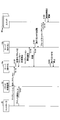
- FIG. 4 is a sequence diagram for explaining an example of a processing procedure related to the VNF migration in the first embodiment.
- FIG. 4 illustrates an example in which a VNF operating in the server 10a is migrated to the server 10b. That is, in the migration, the server 10a is the migration source and the server 10b is the migration destination.
- the server 10a is the migration source
- the server 10b is the migration destination.
- “a” is added to the end of the reference numeral of each part regarding the server 10 a
- “b” is added to the end of the reference numeral of each part relating to the server 10 b.
- the migration instruction unit 21 of the controller 20 responds to an automatic determination or a user instruction, etc., and the VNF (hereinafter referred to as “migration source VNF”) operating on the server 10a with respect to the migration control unit 11a of the server 10a.
- Migration instruction is transmitted (S110).
- the migration destination server 10 is designated.
- the server 10b is the migration destination.
- the instruction includes “address b” as a new address for the migration source VNF.
- the address b is an address assigned (generated) by the migration instruction unit 21 of the controller 20 by a method designated in advance during migration.
- any method can be adopted as long as it can assign an address that does not overlap with other addresses used in the network N1 and does not overlap with the current address (before migration) of the migration source VNF. May be. It is assumed that the current address of the migration source VNF is “address a”.
- the address notification unit 22 of the controller 20 includes the packet processing device 30 that performs packet control such as filtering using the address of the packet. Is notified that the address a and the address b are used by the same VNF (that is, the address a and the address b are notified) (S120). This is because the same processing as that for the packet with address a attached to the source address column is applied to the packet with address b attached to the source address column.
- the address attachment unit 12a in the server 10a that has received the migration instruction starts giving the address b instead of the address a to the packet transmission source address column output from the migration source VNF (S130). Therefore, when each switch 40 receives the packet output from the migration source VNF, it recalculates the route for the address b and updates the route information. However, due to the effect of step S120, the processing on the packet by the packet processing device 30 is the same as the packet in which the address a is attached to the source address column.
- the migration control unit 11a notifies the migration control unit 11b of the migration destination server 10b of the start of migration (S140).
- data synchronization for migration of the migration source VNF is performed between the migration control unit 11a and the migration control unit 11b (S150). That is, data related to the migration source VNF stored in the server 10a is transferred to the server 10b. When the data related to the migration source VNF is updated during the synchronization, the updated part is also transferred to the server 10b. Note that the packet processing by the migration source VNF is continued even during data synchronization. During this time, the address attachment unit 12a assigns the address b to the transmission source address column of the packet output from the migration source VNF.
- the migration destination VNF transmits a broadcast packet (S170).
- the address attachment unit 12b attaches the address a inherited from the migration source VNF to the transmission source address field of the broadcast packet. Accordingly, each switch 40 that has received the broadcast packet updates the route information so that the packet addressed to address a reaches the server 10b (S180).
- the address attachment unit 12a may start giving the address b to the transmission source address column of the packet output from the migration source VNF just before the migration destination VNF transmits the broadcast packet. That is, if it is avoided that addresses overlap between the migration source VNF, the migration destination, and the VNF, the address attachment unit 12a assigns the address b to the transmission source address column of the packet output from the migration source VNF.
- the start timing is not limited to a specific timing.
- the migration control unit 11a monitors whether or not a packet has reached the migration source VNF. If the state where the packet does not reach the migration source VNF continues for a predetermined time or more, the migration control unit 11a determines that the update of the route information by each switch 40 is completed, and stops the migration source VNF (S190).
- the switch 40 performs the route update using the broadcast packet transmitted by the migration destination VNF, it is possible to prevent the renewal of the route information based on the data packet.
- the packet addressed to address a can be delivered to the migration destination VNF. That is, it is possible to avoid communication fraud when transferring software related to packet processing to another computer.
- the address (address a) before the change and the address (address b) after the change are notified to the packet processing device 30 or the like, so that packets having each address as a transmission source (that is, substantially the same VNF) The same processing can be applied to the packet output from (1).
- FIG. 5 is a sequence diagram for explaining an example of a processing procedure related to the VNF migration in the second embodiment.
- the same steps as those in FIG. 4 are denoted by the same step numbers, and the description thereof is omitted.
- step S110a is executed instead of step S110.
- the address b is not specified in the migration instruction in step S110a. Therefore, in the second embodiment, step S130 of FIG. 4 is not executed. That is, the transmission source address of the packet output from the migration source VNF is not changed (the address a remains unchanged).
- the migration instruction unit 21 of the controller 20 assigns (generates) the address b by a method designated in advance, and uses the address b as an address to be assigned to the migration destination VNF. Notify the migration control unit 11b of the server 10b. That is, in the second embodiment, the address of the migration destination VNF is changed instead of the address of the migration source VNF, thereby avoiding duplication of addresses in both.
- the migration control unit 11b activates the migration destination VNF in the server 10b (S160), it notifies the controller 20 of activation of the migration destination VNF (S161).
- the address notification unit 22 of the controller 20 transmits an ARP (Address Resolution Protocol) execution instruction to a device that manages the correspondence between the IP address and the MAC address, such as the packet processing device 30. (S162).
- the execution instruction includes the IP address and MAC address (address b) of the migration destination VNF.
- the packet processing device 30 or the like that has received the execution instruction executes ARP for the IP address (S163). Specifically, the MAC address associated with the IP address is changed to address b.
- step S170a is executed instead of step S170.
- the migration destination VNF transmits a broadcast packet (S170.
- the address attachment unit 12b attaches the address b notified in step S111 to the transmission source address field of the broadcast packet. Therefore, each switch 40 that has received the broadcast packet updates the route information so that the packet addressed to address b reaches the server 10b (S180).
- the VNF migration procedure is merely an example.
- the present embodiment may be applied to the migration of software other than VNF as long as it is software that processes packets.
- the migration control unit 11 is an example of a control unit.
- the address attachment unit 12 is an example of an attachment unit.
- the server 10 is an example of an information processing device.
- the controller 20 is an example of a control device and a notification unit.
- the address notification unit 22 is an example of a notification unit.
Landscapes
- Engineering & Computer Science (AREA)
- Computer Networks & Wireless Communication (AREA)
- Signal Processing (AREA)
- Software Systems (AREA)
- Theoretical Computer Science (AREA)
- Physics & Mathematics (AREA)
- General Engineering & Computer Science (AREA)
- General Physics & Mathematics (AREA)
- Data Exchanges In Wide-Area Networks (AREA)
Abstract
情報処理装置は、パケットの処理を行うソフトウェアについて他のコンピュータへの移行又は他のコンピュータからの移行を制御する制御部と、移行元又は移行先の前記ソフトウェアから出力されるパケットに対して、移行先又は移行元とは異なる送信元アドレスを添付する添付部と、を有することで、パケット処理に関するソフトウェアを他のコンピュータに移行する場合における通信不正の発生を回避する。
Description
本発明は、情報処理装置、制御装置、移行方法及びプログラムに関する。
従来、物理サーバを用いて実現していたアプリケーションの稼働環境をソフトウェアで実現する仮想マシン技術が発達している。仮想マシンはソフトウェアであり、仮想マシンを稼働させる環境を有する物理プラットフォーム上で稼働する。稼働環境を持つサーバが複数存在する場合、仮想マシンを稼働させた状態で、別のサーバ上に当該仮想マシンを移動させ、引き続き稼働させることができる。この動作はライブマイグレーションと呼ばれ、サーバの故障時やメンテナンス時にサービスを継続させる手段として用いられる。
仮想マシン技術が成熟するとともに、仮想マシンを用いてパケット処理を行う、ネットワーク機能仮想化(NFV(Network Functions Virtualization))技術に注目が集まっている。NFV技術では、パケット処理をソフトウェアで行う。パケット処理を行うソフトウェアは仮想ネットワーク機能(VNF(Virtualized Network Function))と呼ばれる。
VNFはパケット処理で使用する、多くのデータを更新する。したがって、VNFをマイグレーションする際、これらのデータを移行元及び移行先において同期する必要がある。同期するデータの量は、仮想マシンを他の用途に使用した場合に比べて大きい。このため、トラヒック量が多い場合、マイグレーション中に移行元のVNFにおいて同期対象のデータに更新が発生し、更新部分についても同期を行うためにマイグレーションに要する時間が長期化して、なかなかマイグレーションが完了しない場合が有る。
この問題を解決するため、VNFを別のサーバに移行する際、移行元のサーバと移行先のサーバ上でVNFを同期し、同期完了後のしばらくの間、両方のサーバ上で同じVNFを稼働させることによりパケット処理を継続する方法が提案されている(非特許文献1)。
杉園 他,"仮想ネットワーク機能に適したライブマイグレーション手法の提案", 電子情報通信学会ソサエティ大会2017年秋
非特許文献1の方式は、VNFの同期が完了した後、レイヤ2スイッチの経路情報を更新する。VNFが処理するデータパケットの転送先を移行前のサーバから移行先のサーバへと変更するためである。
経路情報の更新手順は次のとおりである。
(1)まず、移行先のVNFは、自身のレイヤ2アドレスを送信元アドレス欄に添付したブロードキャストパケットを送信する。
(2)ネットワーク内のレイヤ2スイッチは到着したブロードキャストパケットの送信元アドレス欄とパケット到着ポートとを照合し、移行先VNF宛のパケットの出力先を設定する。
(3)移行先VNF宛のパケットの出力先の設定後、レイヤ2スイッチは、移行先のサーバで稼働するVNFへとデータパケットを転送する。
(1)まず、移行先のVNFは、自身のレイヤ2アドレスを送信元アドレス欄に添付したブロードキャストパケットを送信する。
(2)ネットワーク内のレイヤ2スイッチは到着したブロードキャストパケットの送信元アドレス欄とパケット到着ポートとを照合し、移行先VNF宛のパケットの出力先を設定する。
(3)移行先VNF宛のパケットの出力先の設定後、レイヤ2スイッチは、移行先のサーバで稼働するVNFへとデータパケットを転送する。
Ethernet(登録商標)における経路情報更新メカニズムには、全スイッチが経路情報を更新し、正しくパケットを出力するまで時間がかかるという課題が有る。非特許文献1の方式では、同期完了後も移行元のサーバでVNFが稼働し、当該VNFが移行元のサーバに到着したデータパケットを処理する。移行元のVNFが処理したデータパケットの送信元アドレスには当該VNFのアドレスが添付される。このとき、移行先のVNFが送信したブロードキャストパケットと、移行元のVNFが送信したデータパケットに添付されたパケットの送信元を示すアドレスが同じになる(すなわち、移行元と移行先とでアドレスが重複してしまう。)。
移行元のVNFが送信したデータパケットもレイヤ2スイッチの経路更新処理を引き起こすトリガーとなるため、移行先VNFが送信したブロードキャストパケットにより更新された経路情報は、移行元VNFが送信したデータパケットにより再更新される。その結果、データパケットは再び移行元に届き、移行先にデータパケットが届かなくなってしまう。
本発明は、上記の点に鑑みてなされたものであって、パケット処理に関するソフトウェアを他のコンピュータに移行する場合における通信不正の発生を回避することを目的とする。
そこで上記課題を解決するため、情報処理装置は、パケットの処理を行うソフトウェアについて他のコンピュータへの移行又は他のコンピュータからの移行を制御する制御部と、移行元又は移行先の前記ソフトウェアから出力されるパケットに対して、移行先又は移行元とは異なる送信元アドレスを添付する添付部と、を有する。
パケット処理に関するソフトウェアを他のコンピュータに移行する場合における通信不正の発生を回避することができる。
以下、図面に基づいて本発明の実施の形態を説明する。図1は、第1の実施の形態におけるデータ転送システム1の構成例を示す図である。図1に示されるデータ転送システム1において、サーバ10a及びサーバ10b等の複数のサーバ10と、コントローラ20と、1以上のパケット処理装置30とは、ネットワークN1を介して接続されている。ネットワークN1は、1以上のスイッチ40を含むレイヤ2のネットワーク(すなわち、LAN(Local Area Network)である。
サーバ10は、仮想マシンが稼働するコンピュータである。本実施の形態では、仮想マシン上でVNF(Virtualized Network Function)機能を実現するソフトウェア(以下、単に「VNFプロセス」という。)のプロセスがサーバ10において稼働する。
コントローラ20は、VNFのマイグレーション(ライブマイグレーション)をサーバ10に指示したり、マイグレーションに伴う各種の通知をパケット処理装置30等に対して行ったりするコンピュータである。コントローラ20には、VNFと、当該VNFに関するパケット処理を行うパケット処理装置30との対応情報等が記憶されている。
パケット処理装置30は、パケットのヘッダからアドレスなどの情報を入手し、当該アドレスに基づいて当該パケットに対する処理を行う。例えば、NAPT(Network Address and Port Translation)を行う装置、ファイヤーウォールとして機能する装置、又はSDN(Software Defined Network)スイッチ等がパケット処理装置30であってもよい。なお、本実施の形態において、「パケット」とは、特段の断りが無い限りレイヤ2のパケット(フレーム)を意味する。また、アドレスとは、特段の断りが無い限りレイヤ2のアドレス(MACアドレス)を意味する。
図2は、第1の実施の形態におけるサーバ10のハードウェア構成例を示す図である。図2のサーバ10は、それぞれバスBで相互に接続されているドライブ装置100、補助記憶装置102、メモリ装置103、CPU104、及びインタフェース装置105等を有する。
サーバ10での処理を実現するプログラムは、CD-ROM等の記録媒体101によって提供される。プログラムを記憶した記録媒体101がドライブ装置100にセットされると、プログラムが記録媒体101からドライブ装置100を介して補助記憶装置102にインストールされる。但し、プログラムのインストールは必ずしも記録媒体101より行う必要はなく、ネットワークを介して他のコンピュータよりダウンロードするようにしてもよい。補助記憶装置102は、インストールされたプログラムを格納すると共に、必要なファイルやデータ等を格納する。
メモリ装置103は、プログラムの起動指示があった場合に、補助記憶装置102からプログラムを読み出して格納する。CPU104は、メモリ装置103に格納されたプログラムに従ってサーバ10に係る機能を実行する。インタフェース装置105は、ネットワークに接続するためのインタフェースとして用いられる。
なお、コントローラ20、パケット処理装置30及びスイッチ40等も、図2に示されるハードウェアを有してもよい。
図3は、第1の実施の形態におけるサーバ10及びコントローラ20の機能構成例を示す図である。図3において、サーバ10は、マイグレーション制御部11及びアドレス添付部12等を有する。これら各部は、サーバ10にインストールされた1以上のプログラムが、CPU104に実行させる処理により実現される。
マイグレーション制御部11は、当該サーバ10において稼働するVNFの移行先へのマイグレーション(移行)、又は他のサーバ10において稼働するVNFの移行元(当該他のサーバ10)からのマイグレーションを制御する。
アドレス添付部12は、当該サーバ10において稼働するVNFから出力されるパケットの送信元アドレス欄に対して、当該VNFに割り当てられたアドレスを添付(付与)する。
一方、コントローラ20は、マイグレーション指示部21及びアドレス通知部22等を有する。これら各部は、コントローラ20にインストールされた1以上のプログラムが、コントローラ20のCPUに実行させる処理により実現される。
マイグレーション指示部21は、移行元のサーバ10に対し、VNFのマイグレーションの指示を行う。
アドレス通知部22は、移行元及び移行先のサーバ10における各VNFから出力されるパケットが、各パケット処理装置30によって同様に扱われるようにするために、当該各VNFのアドレスを各パケット処理装置30に通知する。
以下、データ転送システム1において実行される処理手順について説明する。図4は、第1の実施の形態におけるVNFのマイグレーションに関する処理手順の一例を説明するためのシーケンス図である。図4では、サーバ10aにおいて稼働するVNFがサーバ10bへマイグレーション(移行)される例について説明する。すなわち、当該マイグレーションにおいて、サーバ10aが移行元であり、サーバ10bが移行先である。図4の説明において、図3に示した機能構成について、サーバ10aに関する各部の符号の末尾には「a」が付与され、サーバ10bに関する各部の符号の末尾には「b」が付与される。
例えば、コントローラ20のマイグレーション指示部21が、自動的な判断又はユーザによる指示等に応じ、サーバ10aのマイグレーション制御部11aに対して、サーバ10aで稼働するVNF(以下、「移行元VNF」という。)のマイグレーションの指示を送信する(S110)。当該指示では、移行先のサーバ10が指定される。ここでは、サーバ10bが移行先であることが指定される。また、当該指示には、移行元VNFに対する新たなアドレスとして「アドレスb」が含まれる。アドレスbは、コントローラ20のマイグレーション指示部21が、マイグレーションに際して、予め指定された方法により割り当てる(生成する)アドレスである。当該方法としては、ネットワークN1において使用されている他のアドレスと重複せず、移行元VNFの現時点の(移行前の)アドレスとも重複しないアドレスを割り当て可能な方法であれば、いかなる方法が採用されてもよい。なお、移行元VNFの現時点のアドレスは、「アドレスa」であるとする。
ステップS110に続いて、又はステップS110と並行して、コントローラ20のアドレス通知部22は、パケットのアドレスを用いてフィルタリングなどのパケット制御を行うパケット処理装置30が存在する場合、当該パケット処理装置30に対して、アドレスa及びアドレスbが、同じVNFにより使用されていることを通知する(すなわち、アドレスa及びアドレスbを通知する)(S120)。アドレスbが送信元アドレス欄に添付されているパケットに対し、アドレスaが送信元アドレス欄に添付されているパケットと同じ処理が適用されるようにするためである。
一方、マイグレーションの指示を受けたサーバ10aにおけるアドレス添付部12aは、移行元VNFから出力されるパケット送信元アドレス欄に対して、アドレスaではなくアドレスbの付与を開始する(S130)。したがって、各スイッチ40は、移行元VNFから出力されるパケットを受信すると、アドレスbに対する経路を再計算して、経路情報を更新する。但し、ステップS120の効果により、パケット処理装置30による当該パケットに対する処理は、送信元アドレス欄に対してアドレスaが添付されているパケットと同様となる。
続いて、マイグレーション制御部11aは、マイグレーションの指示に応じ、移行先のサーバ10bのマイグレーション制御部11bに対して、マイグレーションの開始を通知する(S140)。
続いて、マイグレーション制御部11a及びマイグレーション制御部11bの間で、移行元VNFのマイグレーションのためのデータの同期が行われる(S150)。すなわち、サーバ10aに記憶されている移行元VNFに関するデータが、サーバ10bへ転送される。同期中に移行元VNFに関するデータに更新が発生した場合、更新部分もサーバ10bへ転送される。なお、データの同期中においても、移行元VNFによるパケット処理は継続される。この間において、アドレス添付部12aは、移行元VNFから出力されるパケットの送信元アドレス欄に対してアドレスbを付与する。
データの同期が完了し、マイグレーション制御部11bが、サーバ10bにおいて移行先VNFを起動すると(S160)、移行先VNFは、ブロードキャストパケットを送信する(S170)。この際、アドレス添付部12bは、当該ブロードキャストパケットの送信元アドレス欄に対して、移行元VNFから引き継がれたアドレスaを添付する。したがって、当該ブロードキャストパケットを受信した各スイッチ40は、アドレスa宛てのパケットがサーバ10bに届くように、経路情報を更新する(S180)。
なお、アドレス添付部12aが、移行元VNFから出力されるパケットの送信元アドレス欄に対してアドレスbの付与を開始するのは、移行先VNFがブロードキャストパケットを送信する直前でもよい。すなわち、移行元VNFと移行先とVNFとの間でアドレスが重複することが避けられれば、アドレス添付部12aが移行元VNFから出力されるパケットの送信元アドレス欄に対してアドレスbの付与を開始するタイミングは、特定のタイミングに限定されない。
その後、マイグレーション制御部11aは、移行元VNFへのパケットの到達の有無を監視する。移行元VNFに対してパケットが到達しない状況が所定時間以上継続すると、マイグレーション制御部11aは、各スイッチ40による経路情報の更新が終了したと判断し、移行元VNFを停止する(S190)。
上述したように、第1の実施の形態によれば、移行元VNFと移行先VNFとの間でアドレスが重複する事態の発生を回避することができる。したがって、移行先VNFが送信したブロードキャストパケットによる経路更新をスイッチ40が行う際、当該データパケットに基づく経路情報の再更新の発生を防止することが可能になる。その結果、アドレスa宛てのパケットが移行先VNFに届けられるようにすることができる。すなわち、パケット処理に関するソフトウェアを他のコンピュータに移行する場合における通信不正の発生を回避することができる。
また、変更前のアドレス(アドレスa)及び変更後のアドレス(アドレスb)が、パケット処理装置30等に通知されることで、各アドレスを送信元とするパケット(すなわち、実質的に同一のVNFから出力されるパケット)に対して同様の処理が適用されるようにすることができる。
次に、第2の実施の形態について説明する。第2の実施の形態では第1の実施の形態と異なる点について説明する。第2の実施の形態において特に言及されない点については、第1の実施の形態と同様でもよい。
図5は、第2の実施の形態におけるVNFのマイグレーションに関する処理手順の一例を説明するためのシーケンス図である。図5中、図4と同一ステップには同一ステップ番号を付し、その説明は省略する。
図5では、ステップS110の代わりにS110aが実行される。ステップS110aにおけるマイグレーションの指示には、アドレスbは指定されない。したがって、第2の実施の形態において、図4のステップS130は実行されない。すなわち、移行元VNFから出力されるパケットの送信元アドレスは変更されない(アドレスaのままである)。
ステップS110aに続いて、又はステップS110aと並行して、コントローラ20のマイグレーション指示部21は、アドレスbを予め指定された方法により割り当て(生成し)、アドレスbを、移行先VNFに割り当てるアドレスとして、サーバ10bのマイグレーション制御部11bへ通知する。すなわち、第2の実施の形態では、移行元VNFのアドレスではなく、移行先VNFのアドレスが変更されることにより、両者でのアドレスの重複が回避される。
マイグレーション制御部11bは、サーバ10bにおいて移行先VNFを起動すると(S160)、コントローラ20に対して移行先VNFの起動を通知する(S161)。コントローラ20のアドレス通知部22は、当該通知に応じて、パケット処理装置30等、IPアドレスとMACアドレスとの対応を管理している装置に対して、ARP(Address Resolution Protocol)の実行指示を送信する(S162)。当該実行指示には、移行先VNFのIPアドレスとMACアドレス(アドレスb)とが含まれる。当該実行指示を受信したパケット処理装置30等は、当該IPアドレスに対するARPを実行する(S163)。具体的には、当該IPアドレスに対応付けるMACアドレスをアドレスbへ変更する。
また、図5では、ステップS170の代わりにステップS170aが実行される。ステップS170aにおいて、移行先VNFは、ブロードキャストパケットを送信する(S170。この際、アドレス添付部12bは、当該ブロードキャストパケットの送信元アドレス欄に対して、ステップS111において通知されたアドレスbを添付する。したがって、当該ブロードキャストパケットを受信した各スイッチ40は、アドレスb宛てのパケットがサーバ10bに届くように、経路情報を更新する(S180)。
上述したように、第2の実施の形態によっても第1の実施の形態と同様の効果を得ることができる。
なお、上記各実施の形態において、VNFのマイグレーションの手順は一例に過ぎない。また、本実施の形態は、パケットの処理を行うソフトウェアであれば、VNF以外のソフトウェアの移行に関して適用されてもよい。
なお、上記各実施の形態において、マイグレーション制御部11は、制御部の一例である。アドレス添付部12は、添付部の一例である。サーバ10は、情報処理装置の一例である。コントローラ20は、制御装置及び通知部の一例である。アドレス通知部22は、通知部の一例である。
以上、本発明の実施の形態について詳述したが、本発明は斯かる特定の実施形態に限定されるものではなく、請求の範囲に記載された本発明の要旨の範囲内において、種々の変形・変更が可能である。
10 サーバ
11 マイグレーション制御部
12 アドレス添付部
20 コントローラ
21 マイグレーション指示部
22 アドレス通知部
30 パケット処理装置
40 スイッチ
100 ドライブ装置
101 記録媒体
102 補助記憶装置
103 メモリ装置
104 CPU
105 インタフェース装置
B バス
11 マイグレーション制御部
12 アドレス添付部
20 コントローラ
21 マイグレーション指示部
22 アドレス通知部
30 パケット処理装置
40 スイッチ
100 ドライブ装置
101 記録媒体
102 補助記憶装置
103 メモリ装置
104 CPU
105 インタフェース装置
B バス
Claims (7)
- パケットの処理を行うソフトウェアについて他のコンピュータへの移行又は他のコンピュータからの移行を制御する制御部と、
移行元又は移行先の前記ソフトウェアから出力されるパケットに対して、移行先又は移行元とは異なる送信元アドレスを添付する添付部と、
を有することを特徴とする情報処理装置。 - 前記添付部は、他のコンピュータから通知されるアドレスを前記送信元アドレスとする、
ことを特徴とする請求項1記載の情報処理装置。 - 請求項1又は2記載の情報処理装置に対して前記移行の指示を行う制御装置であって、
前記ソフトウェアから出力されるパケットを処理する装置に対し、前記移行元及び前記移行先のアドレスを通知する通知部、
を有することを特徴とする制御装置。 - パケットの処理を行うソフトウェアについて他のコンピュータへの移行又は他のコンピュータからの移行を制御する制御手順と、
移行元又は移行先の前記ソフトウェアから出力されるパケットに対して、移行先又は移行元とは異なる送信元アドレスを添付する添付手順と、
をコンピュータが実行することを特徴とする移行方法。 - 請求項1又は2記載の情報処理装置に対して前記移行の指示を行う制御装置が、
前記ソフトウェアから出力されるパケットを処理する装置に対し、前記移行元及び前記移行先のアドレスを通知する通知手順、
を実行することを特徴とする移行方法。 - パケットの処理を行うソフトウェアについて他のコンピュータへの移行又は他のコンピュータからの移行を制御する制御手順と、
移行元又は移行先の前記ソフトウェアから出力されるパケットに対して、移行先又は移行元とは異なる送信元アドレスを添付する添付手順と、
をコンピュータに実行させることを特徴とするプログラム。 - 請求項1又は2記載の情報処理装置に対して前記移行の指示を行う制御装置に、
前記ソフトウェアから出力されるパケットを処理する装置に対し、前記移行元及び前記移行先のアドレスを通知する通知手順、
を実行させることを特徴とするプログラム。
Priority Applications (1)
| Application Number | Priority Date | Filing Date | Title |
|---|---|---|---|
| US17/052,600 US20210185147A1 (en) | 2018-05-24 | 2019-05-13 | Information processing apparatus, control apparatus, migration method and program |
Applications Claiming Priority (2)
| Application Number | Priority Date | Filing Date | Title |
|---|---|---|---|
| JP2018-099560 | 2018-05-24 | ||
| JP2018099560A JP6950625B2 (ja) | 2018-05-24 | 2018-05-24 | 情報処理装置、制御装置、移行方法及びプログラム |
Publications (1)
| Publication Number | Publication Date |
|---|---|
| WO2019225367A1 true WO2019225367A1 (ja) | 2019-11-28 |
Family
ID=68616712
Family Applications (1)
| Application Number | Title | Priority Date | Filing Date |
|---|---|---|---|
| PCT/JP2019/018868 Ceased WO2019225367A1 (ja) | 2018-05-24 | 2019-05-13 | 情報処理装置、制御装置、移行方法及びプログラム |
Country Status (3)
| Country | Link |
|---|---|
| US (1) | US20210185147A1 (ja) |
| JP (1) | JP6950625B2 (ja) |
| WO (1) | WO2019225367A1 (ja) |
Cited By (1)
| Publication number | Priority date | Publication date | Assignee | Title |
|---|---|---|---|---|
| WO2022079906A1 (ja) * | 2020-10-16 | 2022-04-21 | 日本電信電話株式会社 | 転送経路変更システム、パケット処理装置、監督装置、転送経路変更方法、及びプログラム |
Families Citing this family (1)
| Publication number | Priority date | Publication date | Assignee | Title |
|---|---|---|---|---|
| US12549625B2 (en) * | 2023-09-26 | 2026-02-10 | Dell Products L.P. | Mobility-aware iterative SFC migration in a dynamic 5G edge environment |
Citations (4)
| Publication number | Priority date | Publication date | Assignee | Title |
|---|---|---|---|---|
| JP2012004781A (ja) * | 2010-06-16 | 2012-01-05 | Fujitsu Ltd | 構成情報取得方法、仮想プローブおよび構成情報取得制御装置 |
| JP2014041414A (ja) * | 2012-08-21 | 2014-03-06 | Nippon Telegr & Teleph Corp <Ntt> | 仮想マシンのマイグレーションシステム、制御装置およびマイグレーション方法 |
| JP2017130786A (ja) * | 2016-01-20 | 2017-07-27 | 日本電信電話株式会社 | 管理システム、管理方法及び管理プログラム |
| JP2018005664A (ja) * | 2016-07-05 | 2018-01-11 | 富士通株式会社 | 制御装置、情報処理システム、制御方法、及び、情報処理プログラム |
Family Cites Families (2)
| Publication number | Priority date | Publication date | Assignee | Title |
|---|---|---|---|---|
| JP5486526B2 (ja) * | 2011-02-17 | 2014-05-07 | 日本電信電話株式会社 | 制御装置、制御システム、制御方法、及び制御プログラム |
| JP5964786B2 (ja) * | 2013-06-24 | 2016-08-03 | 日本電信電話株式会社 | 管理装置、通信システム、管理方法、および、管理プログラム |
-
2018
- 2018-05-24 JP JP2018099560A patent/JP6950625B2/ja active Active
-
2019
- 2019-05-13 US US17/052,600 patent/US20210185147A1/en not_active Abandoned
- 2019-05-13 WO PCT/JP2019/018868 patent/WO2019225367A1/ja not_active Ceased
Patent Citations (4)
| Publication number | Priority date | Publication date | Assignee | Title |
|---|---|---|---|---|
| JP2012004781A (ja) * | 2010-06-16 | 2012-01-05 | Fujitsu Ltd | 構成情報取得方法、仮想プローブおよび構成情報取得制御装置 |
| JP2014041414A (ja) * | 2012-08-21 | 2014-03-06 | Nippon Telegr & Teleph Corp <Ntt> | 仮想マシンのマイグレーションシステム、制御装置およびマイグレーション方法 |
| JP2017130786A (ja) * | 2016-01-20 | 2017-07-27 | 日本電信電話株式会社 | 管理システム、管理方法及び管理プログラム |
| JP2018005664A (ja) * | 2016-07-05 | 2018-01-11 | 富士通株式会社 | 制御装置、情報処理システム、制御方法、及び、情報処理プログラム |
Cited By (1)
| Publication number | Priority date | Publication date | Assignee | Title |
|---|---|---|---|---|
| WO2022079906A1 (ja) * | 2020-10-16 | 2022-04-21 | 日本電信電話株式会社 | 転送経路変更システム、パケット処理装置、監督装置、転送経路変更方法、及びプログラム |
Also Published As
| Publication number | Publication date |
|---|---|
| JP6950625B2 (ja) | 2021-10-13 |
| JP2019205079A (ja) | 2019-11-28 |
| US20210185147A1 (en) | 2021-06-17 |
Similar Documents
| Publication | Publication Date | Title |
|---|---|---|
| US10972341B2 (en) | Subnet stretching via layer three communications | |
| US9396022B2 (en) | Information processing system | |
| JP2010114665A (ja) | 通信データ制御方法及び計算機システム | |
| US11868794B2 (en) | Network system, management method and apparatus thereof, and server | |
| KR20170078799A (ko) | 가상 네트워크 기능 인스턴스를 이동하기 위한 방법, 장치 및 시스템 | |
| US11153269B2 (en) | On-node DHCP implementation for virtual machines | |
| CN105743792A (zh) | 流表更新方法及装置 | |
| JP5018969B2 (ja) | 通信制御プログラム、通信制御装置、通信制御システムおよび通信制御方法 | |
| JP2009187090A (ja) | クラスタシステムおよび情報処理方法 | |
| WO2019225367A1 (ja) | 情報処理装置、制御装置、移行方法及びプログラム | |
| CN112948057A (zh) | 虚拟机迁移控制方法、云管理平台、sdn管理器 | |
| JP5813534B2 (ja) | 仮想マシンにアドレスを割り当てるプログラム、方法及び物理サーバ | |
| CN112667293B (zh) | 一种部署操作系统的方法、装置及存储介质 | |
| JP6445408B2 (ja) | 通信システムおよび設定方法 | |
| CN113439245A (zh) | 经由用于传输时间关键数据的通信网络提供控制应用的方法和协调装置 | |
| JP5580766B2 (ja) | サーバ装置、パケット伝送システム、パケット伝送方法及びプログラム | |
| JP6285877B2 (ja) | オーバレイトンネル制御システム及びオーバレイトンネル制御方法 | |
| JP2006054766A (ja) | 冗長構成ネットワークシステムにおける制御データ共有方法 | |
| TWI858448B (zh) | 基於軟體定義網路之虛擬機動態搬遷系統及方法 | |
| KR102567139B1 (ko) | 엣지 플랫폼 관리장치 및 엣지 플랫폼 관리장치의 동작 방법 | |
| JP5992245B2 (ja) | 仮想マシンのマイグレーションシステムおよびその方法 | |
| CN114760242A (zh) | 虚拟路由器的迁移方法、装置、电子设备及存储介质 | |
| CN114866509A (zh) | 虚拟ip切换方法、装置和系统 | |
| CN107342956A (zh) | 一种实现广播处理的方法及装置 | |
| JP2016052080A (ja) | 通信システムおよびその方法 |
Legal Events
| Date | Code | Title | Description |
|---|---|---|---|
| 121 | Ep: the epo has been informed by wipo that ep was designated in this application |
Ref document number: 19807180 Country of ref document: EP Kind code of ref document: A1 |
|
| NENP | Non-entry into the national phase |
Ref country code: DE |
|
| 122 | Ep: pct application non-entry in european phase |
Ref document number: 19807180 Country of ref document: EP Kind code of ref document: A1 |