WO2019225005A1 - 熱交換器及び冷凍サイクル装置 - Google Patents
熱交換器及び冷凍サイクル装置 Download PDFInfo
- Publication number
- WO2019225005A1 WO2019225005A1 PCT/JP2018/020168 JP2018020168W WO2019225005A1 WO 2019225005 A1 WO2019225005 A1 WO 2019225005A1 JP 2018020168 W JP2018020168 W JP 2018020168W WO 2019225005 A1 WO2019225005 A1 WO 2019225005A1
- Authority
- WO
- WIPO (PCT)
- Prior art keywords
- heat exchanger
- pipe
- working fluid
- refrigerant
- sub
- Prior art date
- Legal status (The legal status is an assumption and is not a legal conclusion. Google has not performed a legal analysis and makes no representation as to the accuracy of the status listed.)
- Ceased
Links
Images



Classifications
-
- F—MECHANICAL ENGINEERING; LIGHTING; HEATING; WEAPONS; BLASTING
- F25—REFRIGERATION OR COOLING; COMBINED HEATING AND REFRIGERATION SYSTEMS; HEAT PUMP SYSTEMS; MANUFACTURE OR STORAGE OF ICE; LIQUEFACTION SOLIDIFICATION OF GASES
- F25B—REFRIGERATION MACHINES, PLANTS OR SYSTEMS; COMBINED HEATING AND REFRIGERATION SYSTEMS; HEAT PUMP SYSTEMS
- F25B13/00—Compression machines, plants or systems, with reversible cycle
-
- F—MECHANICAL ENGINEERING; LIGHTING; HEATING; WEAPONS; BLASTING
- F25—REFRIGERATION OR COOLING; COMBINED HEATING AND REFRIGERATION SYSTEMS; HEAT PUMP SYSTEMS; MANUFACTURE OR STORAGE OF ICE; LIQUEFACTION SOLIDIFICATION OF GASES
- F25B—REFRIGERATION MACHINES, PLANTS OR SYSTEMS; COMBINED HEATING AND REFRIGERATION SYSTEMS; HEAT PUMP SYSTEMS
- F25B39/00—Evaporators; Condensers
-
- F—MECHANICAL ENGINEERING; LIGHTING; HEATING; WEAPONS; BLASTING
- F25—REFRIGERATION OR COOLING; COMBINED HEATING AND REFRIGERATION SYSTEMS; HEAT PUMP SYSTEMS; MANUFACTURE OR STORAGE OF ICE; LIQUEFACTION SOLIDIFICATION OF GASES
- F25B—REFRIGERATION MACHINES, PLANTS OR SYSTEMS; COMBINED HEATING AND REFRIGERATION SYSTEMS; HEAT PUMP SYSTEMS
- F25B5/00—Compression machines, plants or systems, with several evaporator circuits, e.g. for varying refrigerating capacity
- F25B5/02—Compression machines, plants or systems, with several evaporator circuits, e.g. for varying refrigerating capacity arranged in parallel
-
- F—MECHANICAL ENGINEERING; LIGHTING; HEATING; WEAPONS; BLASTING
- F25—REFRIGERATION OR COOLING; COMBINED HEATING AND REFRIGERATION SYSTEMS; HEAT PUMP SYSTEMS; MANUFACTURE OR STORAGE OF ICE; LIQUEFACTION SOLIDIFICATION OF GASES
- F25B—REFRIGERATION MACHINES, PLANTS OR SYSTEMS; COMBINED HEATING AND REFRIGERATION SYSTEMS; HEAT PUMP SYSTEMS
- F25B6/00—Compression machines, plants or systems, with several condenser circuits
- F25B6/04—Compression machines, plants or systems, with several condenser circuits arranged in series
Definitions
- the present invention relates to a heat exchanger and a refrigeration cycle apparatus having a heat exchanger, and more particularly to a change in the path configuration of a working fluid in the heat exchanger.
- some refrigeration cycle apparatuses have a heat source side unit and a load side unit.
- the heat source side unit includes a compressor, a heat source side heat exchanger, and a four-way valve
- the load side unit includes a load side heat exchanger.
- the compressor, the heat source side heat exchanger, the four-way valve, and the load side heat exchanger are connected by piping, and a refrigerant circuit is formed in which the refrigerant circulates in the piping.
- the four-way valve By controlling the four-way valve, the direction of the refrigerant flow in the refrigerant circuit is switched, and the heating operation and the cooling operation of the refrigeration cycle apparatus are switched.
- Patent Document 1 describes an outdoor heat exchanger configured to change a refrigerant path configuration in accordance with the direction of the refrigerant flow in the refrigerant circuit as a heat source side heat exchanger.
- the refrigerant flow path is divided into a first unit flow path and a second unit flow path, and various types of flow paths are connected to the first unit flow path and the second unit flow path.
- a valve is provided.
- the present invention has been made to solve the above problems, and provides a heat exchanger and a refrigeration cycle apparatus in which the refrigerant path configuration during cooling operation and heating operation is realized with a simple configuration. For the purpose.
- a heat exchanger includes a heat transfer tube through which a working fluid flows, and a header to which the heat transfer tube is connected, and performs heat exchange between the working fluid and a gas.
- a first valve mechanism that is allowed only in a direction from the sub region toward the main region, a first pipe through which the working fluid flows into and out of the heat exchanger, the main heat exchange unit, and the first sub heat exchange unit. And is allowed to flow only in the direction from the first pipe toward the side where the distributor and the first sub heat exchange section are arranged. And a two-valve mechanism.
- the refrigeration cycle apparatus according to the present invention includes such a heat exchanger.
- the heat exchanger and the refrigeration cycle apparatus since the first valve mechanism and the second valve mechanism that allow the flow of the working fluid only in one direction are provided, the working fluid flowing into the heat exchanger Different paths are formed according to the direction of flow. Therefore, when configuring the path of the working fluid flowing in different directions in the cooling operation and the heating operation, the control by the control device is not necessary, and the control by the control device and the complexity of the substrate of the control device can be suppressed.
- Embodiment 1 is a configuration diagram of a refrigeration cycle apparatus according to Embodiment 1 of the present invention. It is a figure which shows typically the structure of the outdoor heat exchanger which concerns on Embodiment 1 of this invention. It is a figure which shows typically the structure of the outdoor heat exchanger which concerns on the modification of Embodiment 1 of this invention. It is a figure which shows typically the structure of the outdoor heat exchanger which concerns on Embodiment 2 of this invention. It is a figure which shows typically the structure of the outdoor heat exchanger which concerns on Embodiment 3 of this invention. It is a figure which shows typically the structure of the outdoor heat exchanger periphery in the outdoor unit of the refrigerating-cycle apparatus which concerns on Embodiment 4 of this invention.
- FIG. 1 is a configuration diagram of a refrigeration cycle apparatus according to Embodiment 1 of the present invention.
- the refrigeration cycle apparatus 1 includes an outdoor unit 10 that is a heat source side unit and an indoor unit 20 that is a load side unit.
- the outdoor unit 10 and the indoor unit 20 are connected via a gas refrigerant pipe 31 and a liquid refrigerant pipe 32.
- the outdoor unit 10 includes a compressor 11, a flow path switching unit 12, an outdoor heat exchanger 13 that is a heat source side heat exchanger, a first expansion valve 14, a second expansion valve 15, and a refrigerant container 16.
- the indoor unit 20 has an indoor heat exchanger 21 that is a load-side heat exchanger.
- the refrigerant circuit 30 is formed by refrigerant piping including A refrigerant that is a working fluid circulates in the refrigerant circuit.
- the compressor 11 sucks the refrigerant and compresses the sucked refrigerant to be in a high temperature and high pressure state.
- the capacity of the compressor 11, that is, the amount of refrigerant sent out per unit time is changed by arbitrarily changing the operation frequency by an inverter circuit or the like.
- the flow path switching unit 12 switches the flow of the refrigerant in the refrigerant circuit 30 and is, for example, a four-way valve.
- the flow path switching unit 12 is controlled by a control device (not shown).
- the outdoor heat exchanger 13 performs heat exchange between the refrigerant and outdoor air, that is, gas, and functions as a condenser during cooling operation and as an evaporator during heating operation. Outdoor air is supplied to the outdoor heat exchanger 13 by a fan (not shown).
- the first expansion valve 14 and the second expansion valve 15 are valves that depressurize the refrigerant flowing in the refrigerant circuit 30, and are electronic expansion valves that can be adjusted in opening degree.
- the refrigerant container 16 is an excess refrigerant storage container that is provided between the first expansion valve 14 and the second expansion valve 15 and stores excess refrigerant.
- the indoor heat exchanger 21 performs heat exchange between the refrigerant and indoor air, that is, gas, and functions as an evaporator during cooling operation and as a condenser during heating operation. Indoor air is supplied to the indoor heat exchanger 21 by a fan (not shown).
- the solid line arrows indicate the refrigerant flow during the cooling operation
- the dotted line arrows indicate the refrigerant flow during the heating operation.
- the flow path switching unit 12 is switched to a state indicated by a solid arrow by a control device (not shown).
- the gas refrigerant is guided to the outdoor heat exchanger 13 through the flow path switching unit 12.
- the outdoor heat exchanger 13 the gas refrigerant exchanges heat with outdoor air and is condensed to become a liquid refrigerant.
- the liquid refrigerant flowing out of the outdoor heat exchanger 13 is guided to the first expansion valve 14.
- the liquid refrigerant is decompressed by the first expansion valve 14 and enters a gas-liquid two-phase state.
- the refrigerant in the gas-liquid two-phase state passes through the refrigerant container 16, passes through the second expansion valve 15, and is led to the indoor heat exchanger 21 through the liquid refrigerant pipe 32.
- the indoor heat exchanger 21 the refrigerant exchanges heat with room air, evaporates and becomes a low-pressure gas refrigerant.
- the low-pressure gas refrigerant that has flowed out of the indoor heat exchanger 21 is guided to the flow path switching unit 12 via the gas refrigerant pipe 31.
- the low-pressure gas refrigerant is sucked into the compressor 11 through the flow path switching unit 12.
- the flow path switching unit 12 is switched to a state indicated by a dotted arrow by a control device (not shown).
- a control device not shown.
- the gas refrigerant passes through the flow path switching unit 12 and is led to the indoor heat exchanger 21 via the gas refrigerant pipe 31.
- the indoor heat exchanger 21 the gas refrigerant exchanges heat with room air and is condensed to become a liquid refrigerant.
- the liquid refrigerant flowing out of the indoor heat exchanger 21 is guided to the second expansion valve 15 through the liquid refrigerant pipe 32.
- the liquid refrigerant is decompressed by the second expansion valve 15 and enters a gas-liquid two-phase state.
- the refrigerant in the gas-liquid two-phase state passes through the refrigerant container 16, passes through the first expansion valve 14, and is led to the outdoor heat exchanger 13.
- the refrigerant exchanges heat with outdoor air and evaporates to become a gas refrigerant.
- the gas refrigerant flowing out of the outdoor heat exchanger 13 is sucked into the compressor 11 through the flow path switching unit 12.
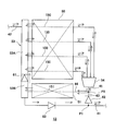
- FIG. 2 is a diagram schematically showing the configuration of the outdoor heat exchanger according to Embodiment 1 of the present invention.
- the solid line arrows indicate the refrigerant flow during the cooling operation
- the dotted line arrows indicate the refrigerant flow during the heating operation.
- a first pipe 41 and a second pipe 42 are connected to the outdoor heat exchanger 13.
- the first piping 41 is connected to the first expansion valve 14 shown in FIG.
- the 2nd piping 42 is connected to the flow-path switching part 12 shown in FIG.
- the refrigerant flows from the second pipe 42 and flows out from the first pipe 41 to the outdoor heat exchanger 13 that operates as a condenser.
- the refrigerant flows from the first pipe 41 and the refrigerant flows out from the second pipe 42 to the outdoor heat exchanger 13 that operates as an evaporator.
- the direction of the refrigerant inflow / outflow in the first pipe 41 and the direction of the refrigerant inflow / outflow in the second pipe 42 are opposite to each other.
- the outdoor heat exchanger 13 includes a main heat exchange unit 50, a first sub heat exchange unit 51, a header 53, and a distributor 54.
- the outdoor heat exchanger 13 is, for example, a fin-and-tube heat exchanger
- the main heat exchanging unit 50 includes a plurality of heat transfer tubes 150
- the first sub heat exchanging unit 51 is transferred to the main heat exchanging unit 50.
- the number of heat transfer tubes 151 is smaller than the number of heat tubes 150.
- the main heat exchange unit 50 and the first sub heat exchange unit 51 have fins (not shown).
- a plurality of heat transfer tubes are arranged in the vertical direction, and the plurality of fins are inserted perpendicular to the plurality of heat transfer tubes arranged in parallel.
- a first sub heat exchange unit 51 is arranged below the main heat exchange unit 50, and the main heat exchange unit 50 and the first sub heat exchange unit 51 are arranged along the vertical direction.
- a plurality of refrigerant paths are formed inside the heat transfer tube 150 of the main heat exchange unit 50 and the heat transfer tube 151 of the first sub heat exchange unit 51.
- the number of passes of the first sub heat exchange unit 51 is smaller than the number of passes of the main heat exchange unit 50.
- four heat transfer tubes 150 are shown in the main heat exchange unit 50, and one heat transfer tube 151 is shown in the first sub heat exchange unit 51, but this conceptually shows a path configuration. Yes, it does not specify the number of heat transfer tubes and the number of passes.
- the total number of heat transfer tubes is determined based on the design of the outdoor heat exchanger 13, and the total number of paths is determined according to the total number of heat transfer tubes.
- the outdoor heat exchanger 13 is configured such that the number of heat transfer tubes 151 of the first sub heat exchange unit 51 is less than the number of heat transfer tubes 150 of the main heat exchange unit 50 in the total number of heat transfer tubes.
- the outdoor heat exchanger 13 is configured such that the number of passes of the first sub heat exchange unit 51 is less than the number of passes of the main heat exchange unit 50 within the total number of passes determined according to the total number of heat transfer tubes. Yes.
- a first pipe 41 and a second pipe 42 are connected to the header 53.
- the header 53 includes a main region 53A to which the heat transfer tube 150 of the main heat exchange unit 50 is connected, and a sub region 53B to which the heat transfer tube 151 of the first sub heat exchange unit 51 is connected.
- the distributor 54 has one end connected to the main heat exchange unit 50 and the other end connected to the first sub heat exchange unit 51. During the heating operation, the refrigerant is distributed to a plurality of paths by the distributor 54 and is guided to the main heat exchange unit 50. During the cooling operation, the refrigerant flowing out from the main heat exchanging unit 50 in a plurality of passes is joined by the distributor 54.
- a third pipe 43 extending from the first pipe 41 branches to the side where the distributor 54 is located at the first branch point P1.
- the fourth pipe 44 connected to the first sub heat exchange unit 51 and the fifth pipe 45 connected to the distributor 54 branch from the third pipe 43 at the second branch point P2.
- a first valve mechanism 61 is provided between the main region 53A and the sub region 53B.
- the first valve mechanism 61 is, for example, a check valve, and allows the refrigerant to flow only in the direction from the sub region 53B toward the main region 53A.
- a second valve mechanism 62 is provided between the first branch point P1 and the second branch point P2.
- the second valve mechanism 62 is, for example, a check valve, and allows the refrigerant to flow only in the direction from the first branch point P1 to the second branch point P2. That is, the second valve mechanism 62 allows the flow of the refrigerant flowing in from the first pipe 41 only in the direction from the first pipe 41 toward the side where the distributor 54 and the first sub heat exchange unit 51 are disposed. To do.
- the third pipe 43 is provided with a third valve mechanism 63.
- the third valve mechanism 63 is, for example, a check valve, and allows the refrigerant to flow only in the direction from the header 53 toward the first branch point P1. That is, the third valve mechanism 63 prevents the refrigerant flowing in from the first pipe 41 from flowing to the header 53 and allows only the refrigerant flowing out from the header 53 to flow out from the first pipe 41.
- the high-temperature and high-pressure gas refrigerant compressed and discharged by the compressor 11 flows into the main region 53A of the header 53 through the second pipe 42. Since the header 53 is provided with the first valve mechanism 61, the gas refrigerant flowing into the header 53 does not flow from the main region 53 ⁇ / b> A to the sub region 53 ⁇ / b> B but is guided only to the main heat exchange unit 50.
- the gas refrigerant is condensed by exchanging heat with outdoor air in the main heat exchanging unit 50, and is in a gas-liquid two-phase state.
- the refrigerant in a gas-liquid two-phase state is divided into a plurality of paths, led to the distributor 54, and merged by the distributor 54.
- a second valve mechanism 62 is provided on the downstream side of the distributor 54. Therefore, the refrigerant in the gas-liquid two-phase state does not flow from the second branch point P2 to the first branch point P1, but is guided only to the first sub heat exchange unit 51.
- the refrigerant in the gas-liquid two-phase state is further subjected to heat exchange with outdoor air in the first sub heat exchange unit 51.
- the refrigerant that has flowed out of the first sub heat exchange unit 51 flows into the sub region 53 ⁇ / b> B of the header 53.
- the main heat exchange unit 50 is provided according to the flow direction of the refrigerant when the refrigeration cycle apparatus 1 performs the cooling operation by the arrangement of the first valve mechanism 61, the second valve mechanism 62, and the third valve mechanism 63.
- the 1st sub heat exchange part 51 is in the state connected in series. That is, the path of the main heat exchange unit 50 and the path of the first sub heat exchange unit 51 are configured to be connected in series during the cooling operation.
- the number of passes of the first sub heat exchange unit 51 is smaller than the number of passes of the main heat exchange unit 50. Therefore, when the refrigerant that has flowed out of the main heat exchange unit 50 passes through the first sub heat exchange unit 51 via the distributor 54, the flow rate of the refrigerant increases. As a result, high heat transfer efficiency can be obtained as a condenser.
- the indoor heat exchanger 21 exchanges heat with indoor air, and the condensed liquid refrigerant is a first expansion valve 14, a refrigerant container 16, and a second expansion valve 15. Then, it flows into the outdoor heat exchanger 13 through the first pipe 41.
- the third pipe 43 branched from the first branch point P1 and extending toward the distributor 54 is provided with a second valve mechanism 62, and the first pipe 41 connected to the header 53 is provided with a third valve mechanism 63. Is provided.
- the second valve mechanism 62 of the third pipe 43 allows the refrigerant to flow only in the direction from the first branch point P1 to the second branch point P2.
- the valve mechanism 63 prevents the refrigerant flowing from the first pipe 41 from flowing to the header 53. Therefore, the refrigerant flowing in from the first pipe 41 is not guided to the header 53 but is guided to the side where the first sub heat exchange unit 51 and the distributor 54 are located. Then, the refrigerant branches at the second branch point P ⁇ b> 2 and is guided to the distributor 54 and the first sub heat exchange unit 51.
- the refrigerant guided to the first sub heat exchange unit 51 is heat-exchanged with outdoor air and is guided to the sub region 53 ⁇ / b> B of the header 53.
- the refrigerant flowing into the distributor 54 is distributed to a plurality of paths by the distributor 54 and is guided to the main heat exchange unit 50.
- the refrigerant guided to the main heat exchange unit 50 is heat-exchanged with outdoor air in the main heat exchange unit 50, and is guided to the main region 53 ⁇ / b> A of the header 53. At this time, there is no pressure difference between the main region 53A and the sub region 53B.
- the first valve mechanism 61 provided between the main region 53A and the sub region 53B allows the refrigerant to flow only in the direction from the sub region 53B toward the main region 53A. Therefore, the refrigerant guided to the sub-region 53B flows into the main region 53A, and merges with the refrigerant that has flowed from the main heat exchange unit 50 in the main region 53A.
- the refrigerant merged in the main region 53 ⁇ / b> A flows out from the outdoor heat exchanger 13 through the first pipe 41.
- the main heat exchange unit 50 is provided according to the flow direction of the refrigerant when the refrigeration cycle apparatus 1 performs the heating operation by arranging the first valve mechanism 61, the second valve mechanism 62, and the third valve mechanism 63. And the 1st sub heat exchange part 51 is in the state connected in parallel. That is, the path of the main heat exchange unit 50 and the path of the first sub heat exchange unit 51 are configured to be connected in parallel during the heating operation. Therefore, the low-pressure liquid refrigerant is distributed to both the main heat exchange unit 50 and the first sub heat exchange unit 51 as a whole.
- the first valve mechanism 61, the second valve mechanism 62, and the third valve that allow the refrigerant to flow only in one direction.
- a valve mechanism 63 is provided on the refrigerant path of the outdoor heat exchanger 13. Accordingly, a path configuration corresponding to each of the refrigerant flow during the cooling operation and the refrigerant flow during the heating operation is formed. Furthermore, in switching between air conditioning and heating, the refrigerant path configuration is switched without controlling the opening and closing of the solenoid valve or the like by the control device. As described above, according to the first embodiment, it is possible to flow the refrigerant with a path configuration suitable for each of the cooling operation and the heating operation without complicating the control of the control device and the substrate of the control device. Is obtained.
- FIG. 3 is a diagram schematically showing a configuration of an outdoor heat exchanger according to a modification of the first embodiment of the present invention.
- the same members as those shown in FIG. 2 are denoted by the same reference numerals.
- the solid line arrows indicate the refrigerant flow during the cooling operation
- the dotted line arrows indicate the refrigerant flow during the heating operation.
- the two first sub heat exchange portions 51 are stacked below the main heat exchange portion 50, and the heat transfer tubes 151 of the two first sub heat exchange portions 51 are disposed in the sub region 53 ⁇ / b> B of the header 53. It is connected.
- the fifth pipe 45 is branched into a sixth pipe 46 connected to one first sub heat exchange section 51 and a seventh pipe 47 connected to the distributor 54. Yes.
- Other configurations are the same as those described in FIG.
- the total number of paths is determined according to the total number of heat transfer tubes determined based on the design of the outdoor heat exchanger 13.
- the outdoor heat exchanger 13 is configured such that the number of heat transfer tubes 151 of the two first sub heat exchange units 51 is smaller than the number of heat transfer tubes 150 of the main heat exchange unit 50. ing. That is, the outdoor heat exchanger 13 is configured such that the number of passes of the two first sub heat exchange units 51 is less than the number of passes of the main heat exchange unit 50 within the total number of passes determined according to the total number of heat transfer tubes. Has been.
- the first valve mechanism 61, the second valve mechanism 62, and the third valve mechanism 63 that allow the flow of the refrigerant only in one direction are provided on the refrigerant path of the outdoor heat exchanger 13. Yes. Accordingly, the same effect as described above can be obtained.
- the two first sub heat exchange units 51 are arranged one above the other, but the number of first sub heat exchange units 51 is not limited to this. You may determine the number of the 1st sub heat exchange parts 51 to three or more in the range accept
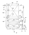
- FIG. FIG. 4 is a diagram schematically showing the configuration of the outdoor heat exchanger according to Embodiment 2 of the present invention. 4, the same components as those in FIGS. 2 and 3 are denoted by the same reference numerals.
- the solid line arrows indicate the refrigerant flow during the cooling operation
- the dotted line arrows indicate the refrigerant flow during the heating operation.
- a second sub heat exchange unit 52 is provided instead of the third valve mechanism 63 of the first embodiment.
- the second sub heat exchange unit 52 has fewer heat transfer tubes 152 than the heat transfer tubes 150 of the main heat exchange unit 50, and has fins (not shown). .
- the second sub heat exchange unit 52 is disposed below the first sub heat exchange unit 51. That is, the main heat exchange part 50, the 1st sub heat exchange part 51, and the 2nd sub heat exchange part 52 are arrange
- the high-temperature and high-pressure gas refrigerant flows into the main region 53A of the header 53 from the second pipe 42, is guided to the main heat exchange unit 50, and is condensed by the main heat exchange unit 50.
- the liquid becomes a two-phase state, passes through the distributor 54, and is led to the first sub heat exchange unit 51. That is, the first valve mechanism 61 does not cause the gas refrigerant to flow into the sub region 53B.
- the second valve mechanism 62 prevents the gas-liquid two-phase refrigerant from flowing from the second branch point P2 to the first branch point P1.
- the refrigerant in the gas-liquid two-phase state that has exchanged heat with outdoor air in the first sub heat exchange section 51 and has flowed out of the first sub heat exchange section 51 flows into the sub region 53B of the header 53, and then the second sub heat exchange It flows into the exchange part 52.
- the refrigerant in the gas-liquid two-phase state is further heat-exchanged with the outdoor air in the second sub heat exchange unit 52 and flows out from the second sub heat exchange unit 52.
- a pressure difference is generated between the upstream and the downstream of the second valve mechanism 62 during the cooling operation.
- the refrigerant that has flowed out of the second sub heat exchange section 52 and led to the first pipe 41 passes through the second valve mechanism 62, and the first sub heat exchange section 51 and the distributor 54 are arranged. It flows out from the outdoor heat exchanger 13 through the first pipe 41 without flowing to the side.
- the liquid refrigerant that has flowed in through the first pipe 41 flows to the second sub heat exchange unit 52, branches at the first branch point P1, and flows to the third pipe 43.
- the liquid refrigerant that has flowed into the second sub heat exchanging section 52 is heat-exchanged with the outdoor air and guided to the sub area 53 ⁇ / b> B of the header 53.
- the liquid refrigerant that has flowed to the third pipe 43 branches at the second branch point P2, flows to the first sub heat exchanger 51 via the fourth pipe 44, and distributes to the distributor 54 via the fifth pipe 45. To flow.
- the liquid refrigerant that has flowed into the first sub heat exchange section 51 is exchanged with the outdoor air and is guided to the sub area 53 ⁇ / b> B of the header 53.
- the refrigerant flowing into the distributor 54 is distributed to a plurality of paths by the distributor 54 and is guided to the main heat exchange unit 50.
- the refrigerant guided to the main heat exchange unit 50 is heat-exchanged with outdoor air in the main heat exchange unit 50, and is guided to the main region 53 ⁇ / b> A of the header 53.
- the first valve mechanism 61 provided between the main region 53A and the sub region 53B allows the refrigerant to flow only in the direction from the sub region 53B toward the main region 53A.
- the refrigerant guided to the sub-region 53B flows into the main region 53A, and merges with the refrigerant that has flowed from the main heat exchange unit 50 in the main region 53A.
- the refrigerant merged in the main region 53A flows out of the outdoor heat exchanger 13 through the second pipe 42.
- the first valve mechanism 61 and the second valve mechanism 62 that allow the flow of the refrigerant only in one direction are provided on the refrigerant path of the outdoor heat exchanger 100,
- the first pipe 41 is provided with a second sub heat exchange unit 52. Therefore, a path configuration corresponding to each of the refrigerant flow during the cooling operation and the refrigerant flow during the heating operation is formed, and the same effect as the above-described effect of the first embodiment is obtained.
- one of the valve mechanisms that allows the refrigerant flow only in one direction is replaced with the sub heat exchange section. Therefore, the number of valve mechanisms of the outdoor heat exchanger 100 can be reduced.
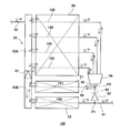
- FIG. 5 is a diagram schematically showing a configuration of an outdoor heat exchanger according to Embodiment 3 of the present invention. 5, the same components as those in FIGS. 2 and 3 are denoted by the same reference numerals.
- the solid arrow indicates the refrigerant flow during the cooling operation
- the dotted arrow indicates the refrigerant flow during the heating operation.
- a three-way valve 110 is provided instead of the first valve mechanism 61, the second valve mechanism 62, and the third valve mechanism 63 of the first embodiment. .
- Other configurations are the same as those in the first embodiment.
- the three-way valve 110 has a first port 111, a second port 112, a third port 113, and a movable mechanism 114.
- the first port 111 is connected to the header 53 via the eighth pipe 48.
- the second port 112 is connected to the first pipe 41.
- the third port 113 is connected to a third pipe 43 that extends to the side where the distributor 54 and the first sub heat exchange unit 51 are located.
- One of the movable mechanism portions 114 is connected to the first pipe 41 via the pipe 121, and the other is connected to the second pipe 42 via the pipe 122.
- a movable member (not shown) that is displaced according to the difference between the pressure of the refrigerant flowing through the first pipe 41 and the pressure of the refrigerant flowing through the second pipe 42 is provided inside the movable mechanism 114.
- the three-way valve 110 is configured such that opening and closing of the first port 111, the second port 112, and the third port 113 is switched according to the position of the movable member.
- the pipe 121 and the pipe 122 are pipes connected to the movable mechanism 114 of the three-way valve 110 in order to acquire the refrigerant pressure difference, and do not constitute the refrigerant circuit 30 of FIG. Therefore, in order to distinguish from other piping which comprises the refrigerant circuit 30, the piping 121 and the piping 122 are shown with the dashed-dotted line in FIG.
- the three-way valve 110 is an autonomous three-way valve in which a path to be communicated is switched according to a pressure difference between the refrigerant flowing into the outdoor heat exchanger 101 and the refrigerant flowing out of the outdoor heat exchanger 101.
- the refrigerant flows in from the second pipe 42, exchanges heat with the outside air in the main heat exchange unit 50 and the first sub heat exchange unit 51, and then flows out from the first pipe 41.
- a pressure loss occurs in the heat exchange in the main heat exchanging part 50 and the first sub heat exchanging part 51. Therefore, during the cooling operation, the pressure of the refrigerant flowing through the second pipe 42 is greater than the pressure of the refrigerant flowing through the first pipe 41. Is also expensive. Therefore, the above-mentioned movable member of the movable mechanism 114 is displaced so that the first port 111 and the second port 112 are opened, the third port 113 is closed, and the first port 111 and the second port 112 are communicated.
- the refrigerant flowing out of the distributor 54 flows only to the first sub heat exchange unit 51.
- the refrigerant flowing out of the header 53 flows through the eighth pipe 48, passes through the three-way valve 110, and is guided to the first pipe 41.
- the refrigerant flows in from the first pipe 41, exchanges heat with the outside air in the main heat exchange unit 50 and the first sub heat exchange unit 51, and then flows out from the second pipe 42.
- a pressure loss occurs in the heat exchange in the main heat exchanging part 50 and the first sub heat exchanging part 51. Therefore, during the heating operation, the pressure of the refrigerant flowing through the first pipe 41 is higher than the pressure of the refrigerant flowing through the second pipe 42. Is also expensive. Therefore, the above-mentioned movable member of the movable mechanism 114 is configured so that the second port 112 and the third port 113 are opened, the first port 111 is closed, and the second port 112 and the third port 113 are communicated. Displace.
- the refrigerant flowing from the first pipe 41 does not flow to the eighth pipe 48 connected to the header 53 but flows only to the third pipe 43 when passing through the three-way valve 110.
- a path configuration in which the main heat exchange unit 50 and the first sub heat exchange unit 51 are connected in parallel during the heating operation is formed.
- the third embodiment according to the pressure difference between the refrigerant flowing into the outdoor heat exchanger 101 and the refrigerant flowing out of the outdoor heat exchanger 101 on the refrigerant path of the outdoor heat exchanger 101.
- a three-way valve 110 that autonomously changes the route is provided. Therefore, a path configuration suitable for both the cooling operation and the heating operation is configured without being controlled by the control device. As a result, the same effects as those of the first and second embodiments described above can be obtained.
- a plurality of first sub heat exchange units 51 may be provided as in the modification of the first embodiment.
- FIG. FIG. 6 is a diagram schematically showing the configuration around the outdoor heat exchanger in the outdoor unit of the refrigeration cycle apparatus according to Embodiment 4 of the present invention.
- the same members as those in FIGS. 1, 2, and 5 are denoted by the same reference numerals.
- the solid line arrows indicate the refrigerant flow during the cooling operation
- the dotted line arrows indicate the refrigerant flow during the heating operation.
- one of the movable mechanism portions 114 of the three-way valve 110 is connected to the second pipe 42 via the pipe 123, and the other is connected to the gas refrigerant pipe 31 via the pipe 124. It is connected.
- the second pipe 42 is connected to a port in the flow path switching unit 12 that communicates with the discharge side of the compressor 11 during the cooling operation and communicates with the suction side of the compressor 11 during the heating operation.
- the gas refrigerant pipe 31 is connected to a port that communicates with the suction side of the compressor 11 during the cooling operation and communicates with the discharge side of the compressor 11 during the heating operation.
- the pipe 123 and the pipe 124 are pipes connected to the movable mechanism 114 of the three-way valve 110 in order to acquire the refrigerant pressure difference, and do not constitute the refrigerant circuit 30 of FIG. Therefore, in order to distinguish from other piping which comprises the refrigerant circuit 30, the piping 123 and the piping 124 are shown with the dashed-dotted line in FIG.
- the three-way valve 110 is configured to switch the communication path according to the pressure difference between the refrigerant on the suction side of the compressor 11 and the refrigerant on the discharge side of the compressor 11. .
- Other configurations are the same as those of the outdoor heat exchanger 101 of the third embodiment.
- the high-temperature and high-pressure gas refrigerant compressed by the compressor 11 flows into the second pipe 42.
- the gas refrigerant pipe 31 flows out of the outdoor heat exchanger 13, passes through the first expansion valve 14, the second expansion valve 15, and the indoor heat exchanger 21 shown in FIG. 1 and is sucked into the compressor 11.
- Low-pressure gas refrigerant flows in. That is, during the cooling operation, the pressure of the refrigerant flowing through the second pipe 42 is higher than the pressure of the refrigerant flowing through the gas refrigerant pipe 31.
- the above-mentioned movable member of the movable mechanism 114 is configured so that the first port 111 and the second port 112 are opened, the third port 113 is closed, and the first port 111 and the second port 112 are communicated. Displace.
- the refrigerant that has flowed out of the distributor 54 flows only to the first sub heat exchange unit 51 at the second branch point P2.
- the refrigerant flowing out of the header 53 flows through the eighth pipe 48, passes through the three-way valve 110, and is guided to the first pipe 41.
- the above-mentioned movable member of the movable mechanism 114 is configured so that the second port 112 and the third port 113 are opened, the first port 111 is closed, and the second port 112 and the third port 113 are communicated. Displace. As a result, the refrigerant flowing from the first pipe 41 does not flow to the eighth pipe 48 connected to the header 53 but flows only to the third pipe 43 when passing through the three-way valve 110. With this configuration, a path configuration in which the main heat exchange unit 50 and the first sub heat exchange unit 51 are connected in parallel during the heating operation is formed.
- the three-way valve 110 is configured to operate according to the pressure difference between the refrigerant on the discharge side and the suction side of the compressor 11.
- the pressure difference between the refrigerant on the discharge side and the suction side of the compressor 11 is significant. Therefore, according to this Embodiment 4, switching of each path
- a plurality of first sub heat exchange units 51 may be provided as in the modification of the first embodiment.
- the heat transfer tube extends laterally on the installation surface, and the main heat exchange unit 50, the first sub heat exchange unit 51, and the second sub heat exchange unit 52 are in the vertical direction.
- the present invention is not limited to this.
- the present invention is also applied to a type of heat exchanger in which heat transfer tubes extend in the vertical direction and are arranged side by side along the horizontal direction.
- the configuration of the outdoor heat exchanger 13 provided in the outdoor unit 10 that is the heat source side unit has been described, but the configuration is not limited thereto.
- a configuration similar to the configuration of the outdoor heat exchanger 13 described above may also be applied to the indoor heat exchanger 21 provided in the indoor unit 20 that is the load side unit.
- 1 refrigeration cycle apparatus 10 outdoor unit, 11 compressor, 12 flow path switching unit, 13 outdoor heat exchanger, 14 first expansion valve, 15 second expansion valve, 16 refrigerant container, 20 indoor unit, 21 indoor heat exchanger , 30 refrigerant circuit, 31 gas refrigerant piping, 32 liquid refrigerant piping, 41 first piping, 42 second piping, 43 third piping, 44 fourth piping, 45 fifth piping, 46 sixth piping, 47 seventh piping, 48 8th pipe, 50 main heat exchange part, 51 1st sub heat exchange part, 52 2nd sub heat exchange part, 53 header, 53A main area, 53B sub area, 54 distributor, 61 1st valve mechanism, 62nd 2 valve mechanism, 63 3rd valve mechanism, 100 outdoor heat exchanger, 101 outdoor heat exchanger, 102 outdoor heat exchanger, 110 three-way valve, 111 1st port, 1 2 2nd port, 113 3rd port, 114 Movable mechanism part, 121 piping, 122 piping, 123 piping, 124 piping, 150 heat transfer
Landscapes
- Engineering & Computer Science (AREA)
- Physics & Mathematics (AREA)
- Mechanical Engineering (AREA)
- Thermal Sciences (AREA)
- General Engineering & Computer Science (AREA)
- Compression-Type Refrigeration Machines With Reversible Cycles (AREA)
Abstract
熱交換器は、メイン熱交換部と、少なくとも1つの第1サブ熱交換部と、メイン熱交換部へ導かれる作動流体を複数のパスに分配する分配器と、ヘッダーに設けられた第1弁機構と、作動流体が入出流する第1配管とメイン熱交換部及び第1サブ熱交換部との間に設けられた第2弁機構とを備える。第1サブ熱交換部は、メイン熱交換部よりも少ない数の伝熱管を有し、メイン熱交換部よりも少ない数の作動流体のパスが形成されている。第1弁機構は、ヘッダーにおいて、メイン熱交換部の伝熱管が接続されているメイン領域と第1サブ熱交換部の伝熱管が接続されているサブ領域との間に設けられ、作動流体の流れをサブ領域からメイン領域へ向かう方向にのみ許容する。第2弁機構は、第1配管から流入した作動流体の流れを、第1配管から分配器及び第1サブ熱交換部が配置されている側へ向かう方向にのみ許容する。
Description
本発明は、熱交換器及び熱交換器を有する冷凍サイクル装置に関するものであり、より詳しくは熱交換器における作動流体のパス構成の変更に関するものである。
従来、冷凍サイクル装置には、熱源側ユニットと負荷側ユニットを有しているものがある。例えば、熱源側ユニットは、圧縮機と熱源側熱交換器と四方弁を備え、負荷側ユニットは、負荷側熱交換器を備えている。圧縮機と熱源側熱交換器と四方弁と負荷側熱交換器が配管で接続され、配管内を冷媒が循環する冷媒回路が形成されている。四方弁を制御することにより、冷媒回路における冷媒の流れの方向が切り替えられ、冷凍サイクル装置の暖房運転と冷房運転が切り替えられる。
特許文献1には、熱源側熱交換器として、冷媒回路における冷媒の流れの方向に応じて、冷媒のパス構成を変更するよう構成されている室外熱交換機が記載されている。特許文献1の室外熱交換機は、冷媒流路が第1単位流路及び第2単位流路に区画されており、第1単位流路及び第2単位流路に接続されている流路に各種バルブが設けられている。そして、暖房運転から冷房運転に切り替えるとき、あるいは冷房運転から暖房運転にきりかえるとき、これらのバルブ及び四方弁の動作を制御装置で制御することにより、冷媒回路における冷媒の流れの方向が切り替えられると共に、パス構成が変更される。
しかしながら、特許文献1の空気調和機における冷暖房の切り替えでは、四方弁の動作及び各種バルブの開閉を連動させなければならない。そのため、制御装置における制御が複雑となり、制御装置に搭載される基板構成が複雑化するという問題がある。
本発明は、上記のような課題を解決するためになされたものであり、冷房運転時及び暖房運転時の冷媒のパス構成が簡易な構成で実現される熱交換器及び冷凍サイクル装置を提供することを目的とする。
本発明に係る熱交換器は、作動流体が流れる伝熱管と、前記伝熱管が接続されているヘッダーとを有し、前記作動流体と気体との間で熱交換を行う熱交換器であって、複数の前記伝熱管を有し、前記複数の前記伝熱管内に前記作動流体の複数のパスが形成されているメイン熱交換部と、前記メイン熱交換部よりも少ない数の前記伝熱管を有し、前記メイン熱交換部よりも少ない数の前記作動流体のパスが形成されている、少なくとも1つの第1サブ熱交換部と、前記メイン熱交換部へ導かれる前記作動流体を前記複数のパスに分配する分配器と、前記ヘッダーにおいて、前記メイン熱交換部の前記伝熱管が接続されているメイン領域と前記第1サブ熱交換部の前記伝熱管が接続されているサブ領域との間に設けられ、前記作動流体の流れを前記サブ領域から前記メイン領域へ向かう方向にのみ許容する第1弁機構と、前記作動流体が前記熱交換器へ入出流する第1配管と前記メイン熱交換部及び前記第1サブ熱交換部との間に設けられ、前記第1配管から流入した前記作動流体の流れを、前記第1配管から前記分配器及び前記第1サブ熱交換部が配置されている側へ向かう方向にのみ許容する第2弁機構とを備えるものである。また、本発明に係る冷凍サイクル装置は、このような熱交換器を備えるものである。
本発明に係る熱交換器及び冷凍サイクル装置によると、一方向にのみ作動流体の流れを許容する第1弁機構及び第2弁機構が設けられているため、熱交換器に流入する作動流体の流れの方向に応じて構成の異なるパスが形成される。従って、冷房運転と暖房運転とで異なる方向に流れる作動流体のパスを構成するに当たり、制御装置による制御が不要となり、制御装置による制御及び制御装置の基板の複雑化を抑えることができる。
以下に、本発明における熱交換器及び冷凍サイクル装置の実施の形態を図面に基づいて詳細に説明する。尚、以下に説明する実施の形態によって本発明が限定されるものではない。また、以下の図面においては各構成部材の大きさ及び形状は実際の装置とは異なる場合がある。
実施の形態1.
図1は、本発明の実施の形態1に係る冷凍サイクル装置の構成図である。冷凍サイクル装置1は、熱源側ユニットである室外ユニット10と負荷側ユニットである室内ユニット20とを備えている。室外ユニット10と室内ユニット20は、ガス冷媒配管31と液冷媒配管32を介して接続されている。室外ユニット10は、圧縮機11と、流路切替部12と、熱源側熱交換器である室外熱交換器13と、第1膨張弁14と、第2膨張弁15と、冷媒容器16とを有している。室内ユニット20は、負荷側熱交換器である室内熱交換器21を有している。圧縮機11、流路切替部12、室外熱交換器13、第1膨張弁14、第2膨張弁15、冷媒容器16、室内熱交換器21、及び上述のガス冷媒配管31と液冷媒配管32を含む冷媒配管で、冷媒回路30が形成されている。冷媒回路内には作動流体である冷媒が循環する。
図1は、本発明の実施の形態1に係る冷凍サイクル装置の構成図である。冷凍サイクル装置1は、熱源側ユニットである室外ユニット10と負荷側ユニットである室内ユニット20とを備えている。室外ユニット10と室内ユニット20は、ガス冷媒配管31と液冷媒配管32を介して接続されている。室外ユニット10は、圧縮機11と、流路切替部12と、熱源側熱交換器である室外熱交換器13と、第1膨張弁14と、第2膨張弁15と、冷媒容器16とを有している。室内ユニット20は、負荷側熱交換器である室内熱交換器21を有している。圧縮機11、流路切替部12、室外熱交換器13、第1膨張弁14、第2膨張弁15、冷媒容器16、室内熱交換器21、及び上述のガス冷媒配管31と液冷媒配管32を含む冷媒配管で、冷媒回路30が形成されている。冷媒回路内には作動流体である冷媒が循環する。
圧縮機11は、冷媒を吸入し、吸入した冷媒を圧縮して高温高圧の状態にするものである。例えばインバータ回路等により、運転周波数を任意に変化させることにより、圧縮機11の容量、すなわち単位時間あたりの冷媒を送り出す量を変化させるものである。
流路切替部12は、冷媒回路30内の冷媒の流れを切り替えるものであり、例えば四方弁である。流路切替部12は、不図示の制御装置により制御される。
室外熱交換器13は、冷媒と、室外空気すなわち気体との間で熱交換を行うものであり、冷房運転時は凝縮器として機能し、暖房運転時は蒸発器として機能する。室外熱交換器13には、不図示のファンにより室外空気が供給される。
第1膨張弁14及び第2膨張弁15は、冷媒回路30内を流れる冷媒を減圧する弁であり、開度の調節が可能な電子膨張弁である。冷媒容器16は、第1膨張弁14と第2膨張弁15との間に設けられ、余剰となる冷媒を貯留する余剰冷媒貯留容器である。
室内熱交換器21は、冷媒と、室内空気すなわち気体との間で熱交換を行うものであり、冷房運転時は蒸発器として機能し、暖房運転時は凝縮器として機能する。室内熱交換器21には、不図示のファンにより室内空気が供給される。
図1において、実線の矢印は冷房運転時の冷媒の流れを示し、点線の矢印は暖房運転時の冷媒の流れを示している。冷房運転時、流路切替部12は、不図示の制御装置により実線の矢印で示す状態に切り替えられる。冷房運転時、圧縮機11から高温高圧のガス冷媒が吐出されると、ガス冷媒は流路切替部12を経て、室外熱交換器13へ導かれる。室外熱交換器13で、ガス冷媒は室外空気と熱交換し凝縮され、液冷媒となる。室外熱交換器13から流出した液冷媒は、第1膨張弁14へ導かれる。液冷媒は、第1膨張弁14で減圧されて気液二相状態となる。気液二相状態となった冷媒は、冷媒容器16を経て、第2膨張弁15を通過し、液冷媒配管32を介して室内熱交換器21へ導かれる。室内熱交換器21において、冷媒は室内空気と熱交換し、蒸発し低圧のガス冷媒となる。室内熱交換器21から流出した低圧のガス冷媒は、ガス冷媒配管31を介して、流路切替部12に導かれる。低圧のガス冷媒は流路切替部12を経て、圧縮機11に吸入される。
暖房運転時、流路切替部12は、不図示の制御装置により点線の矢印で示す状態に切り替えられる。暖房運転時、圧縮機11から高温高圧のガス冷媒が吐出されると、ガス冷媒は流路切替部12を経て、ガス冷媒配管31を介して室内熱交換器21へ導かれる。室内熱交換器21で、ガス冷媒は室内空気と熱交換し凝縮され、液冷媒となる。室内熱交換器21から流出した液冷媒は、液冷媒配管32を介して第2膨張弁15へ導かれる。液冷媒は第2膨張弁15で減圧されて気液二相状態となる。気液二相状態となった冷媒は、冷媒容器16を経て、第1膨張弁14を通過し、室外熱交換器13へ導かれる。室外熱交換器13において、冷媒は室外空気と熱交換し、蒸発しガス冷媒となる。室外熱交換器13から流出したガス冷媒は、流路切替部12を経て、圧縮機11に吸入される。
図2は、本発明の実施の形態1に係る室外熱交換器の構成を模式的に示す図である。図2において、実線の矢印は冷房運転時の冷媒の流れを示し、点線の矢印は暖房運転時の冷媒の流れを示している。
室外熱交換器13には第1配管41と第2配管42が接続されている。第1配管41は、図1に示す第1膨張弁14に接続されている。第2配管42は、図1に示す流路切替部12に接続されている。冷房運転時、凝縮器として動作する室外熱交換器13には、第2配管42から冷媒が流入し、第1配管41から冷媒が流出する。暖房運転時、蒸発器として動作する室外熱交換器13には、第1配管41から冷媒が流入し、第2配管42から冷媒が流出する。冷房運転時及び暖房運転時において、第1配管41における冷媒の入出流の方向と第2配管42における冷媒の入出流の方向は互いに逆方向となっている。
室外熱交換器13は、メイン熱交換部50と、第1サブ熱交換部51と、ヘッダー53と、分配器54とを有している。室外熱交換器13は、例えばフィンアンドチューブ型の熱交換器であり、メイン熱交換部50は複数の伝熱管150を有し、第1サブ熱交換部51は、メイン熱交換部50の伝熱管150の数よりも少ない数の伝熱管151を有している。また、メイン熱交換部50及び第1サブ熱交換部51は図示省略のフィンを有している。メイン熱交換部50及び第1サブ熱交換部51において、複数の伝熱管が上下方向に並設され、複数のフィンは、並設されている複数の伝熱管に対して垂直に挿入されている。メイン熱交換部50の下方に第1サブ熱交換部51が配置されており、メイン熱交換部50と第1サブ熱交換部51は上下方向に沿って配置されている。
メイン熱交換部50の伝熱管150及び第1サブ熱交換部51の伝熱管151の内部には、冷媒の複数のパスが形成されている。第1サブ熱交換部51のパス数は、メイン熱交換部50のパス数よりも少ない。図2では、メイン熱交換部50において4本の伝熱管150が示され、第1サブ熱交換部51において1本の伝熱管151が示されているが、パス構成を概念的に示すものであり、伝熱管の数及びパスの数を特定するものではない。尚、室外熱交換器13の設計に基づいて伝熱管の総数が定められ、パスの総数は伝熱管の総数に従って定められる。伝熱管の総数内において、第1サブ熱交換部51の伝熱管151の数がメイン熱交換部50の伝熱管150の数よりも少なくなるよう、室外熱交換器13は構成されている。そして、伝熱管に総数に従って定められたパスの総数内において、第1サブ熱交換部51のパス数がメイン熱交換部50のパス数よりも少なくなるよう、室外熱交換器13は構成されている。
ヘッダー53には、第1配管41と第2配管42が接続されている。また、ヘッダー53は、メイン熱交換部50の伝熱管150が接続されるメイン領域53Aと、第1サブ熱交換部51の伝熱管151が接続されるサブ領域53Bとを有している。
分配器54は、一方の端部がメイン熱交換部50に接続され、他方の端部が第1サブ熱交換部51に接続されている。暖房運転時、冷媒は分配器54により複数のパスに分配され、メイン熱交換部50に導かれる。冷房運転時、メイン熱交換部50から複数のパスに分かれて流出する冷媒は分配器54で合流する。
第1分岐点P1で、分配器54が位置している側に延びる第3配管43が、第1配管41から分岐している。また、第2分岐点P2で、第1サブ熱交換部51に接続されている第4配管44と分配器54に接続される第5配管45が、第3配管43から分岐している。
ヘッダー53において、メイン領域53Aとサブ領域53Bとの間には、第1弁機構61が設けられている。第1弁機構61は、例えば逆止弁であり、サブ領域53Bからメイン領域53Aへ向かう方向にのみ、冷媒の流れを許容するものである。
第4配管44において、第1分岐点P1と第2分岐点P2の間には、第2弁機構62が設けられている。第2弁機構62は、例えば逆止弁であり、第1分岐点P1から第2分岐点P2へ向かう方向にのみ冷媒の流れを許容するものである。すなわち、第2弁機構62は、第1配管41から流入した冷媒の流れを、第1配管41から、分配器54及び第1サブ熱交換部51が配置されている側へ向かう方向にのみ許容する。
第3配管43には、第3弁機構63が設けられている。第3弁機構63は、例えば逆止弁であり、ヘッダー53から第1分岐点P1へ向かう方向にのみ冷媒の流れを許容するものである。すなわち、第3弁機構63は、第1配管41から流入した冷媒がヘッダー53へ流れることを阻止し、ヘッダー53から流出した冷媒が第1配管41から流出することのみを許容する。
図1の冷凍サイクル装置1が冷房運転するとき、圧縮機11で圧縮され、吐出された高温高圧のガス冷媒は、第2配管42を介してヘッダー53のメイン領域53Aに流入する。ヘッダー53には第1弁機構61が設けられているため、ヘッダー53に流入したガス冷媒は、メイン領域53Aからサブ領域53Bには流れず、メイン熱交換部50にのみ導かれる。ガス冷媒は、メイン熱交換部50で室外空気と熱交換されて凝縮され、気液二相状態となる。気液二相状態となった冷媒は、複数のパスに分かれて分配器54に導かれ、分配器54で合流する。分配器54の下流側には第2弁機構62が設けられている。従って、気液二相状態の冷媒は、第2分岐点P2から第1分岐点P1へは流れず、第1サブ熱交換部51にのみ導かれる。気液二相状態の冷媒は、第1サブ熱交換部51でさらに室外空気と熱交換される。第1サブ熱交換部51から流出した冷媒は、ヘッダー53のサブ領域53Bに流入する。このとき、メイン熱交換部50及び第1サブ熱交換部51における圧力損失により、冷房運転時における第1弁機構61の上流と下流で、すなわち、メイン領域53Aとサブ領域53Bで、圧力差が生じている。従って、第1サブ熱交換部51から流出し、ヘッダー53のサブ領域53Bに流入した冷媒は、第1弁機構61を通過してメイン領域53Aへ導かれることはなく、ヘッダー53から流出し、第1配管41に導かれる。第1配管41の第3弁機構63はヘッダー53から第1分岐点P1へ向かう方向への冷媒の流れ許容するものであるため、第1配管41に導かれた冷媒は、第1配管41を介して室外熱交換器13から流出する。
このように、第1弁機構61、第2弁機構62、及び第3弁機構63の配設により、冷凍サイクル装置1が冷房運転するときの冷媒の流れ方向に応じて、メイン熱交換部50と第1サブ熱交換部51は直列に接続された状態となっている。すなわち、メイン熱交換部50のパスと第1サブ熱交換部51のパスは、冷房運転時には直列に接続された状態となるよう構成されている。そして、第1サブ熱交換部51のパスの数はメイン熱交換部50のパスの数より少ない。従って、メイン熱交換部50から流出した冷媒が分配器54を経て第1サブ熱交換部51を通過するとき、冷媒の流速は上昇する。その結果、凝縮器として高い伝熱効率を得ることができる。
図1の冷凍サイクル装置1が暖房運転するとき、室内熱交換器21で、室内空気と熱交換し、凝縮された液冷媒は、第1膨張弁14、冷媒容器16、及び第2膨張弁15を経て、第1配管41を介して室外熱交換器13に流入する。第1分岐点P1で分岐し分配器54の側に延びる第3配管43には、第2弁機構62が設けられ、ヘッダー53に接続されている第1配管41には、第3弁機構63が設けられている。上述のように、第3配管43の第2弁機構62は、第1分岐点P1から第2分岐点P2へ向かう方向にのみ冷媒の流れを許容するものであり、第1配管41の第3弁機構63は、第1配管41から流入した冷媒がヘッダー53へ流れることを阻止するものである。従って、第1配管41から流入した冷媒は、ヘッダー53には導かれず、第1サブ熱交換部51及び分配器54が位置する側に導かれる。そして、冷媒は、第2分岐点P2で分岐し、分配器54と第1サブ熱交換部51へ導かれる。
第1サブ熱交換部51へ導かれた冷媒は、室外空気と熱交換され、ヘッダー53のサブ領域53Bへ導かれる。一方、分配器54へ流入した冷媒は、分配器54で複数のパスに分配され、メイン熱交換部50へ導かれる。メイン熱交換部50へ導かれた冷媒は、メイン熱交換部50で室外空気と熱交換され、ヘッダー53のメイン領域53Aへ導かれる。このとき、メイン領域53Aとサブ領域53Bで、圧力差は生じていない。そして、メイン領域53Aとサブ領域53Bの間に設けられている第1弁機構61は、サブ領域53Bからメイン領域53Aへ向かう方向にのみ、冷媒の流れを許容するものである。従って、サブ領域53Bに導かれた冷媒はメイン領域53Aに流れ、メイン領域53Aにおいて、メイン熱交換部50から流れてきた冷媒と合流する。メイン領域53Aで合流した冷媒は、第1配管41を介して、室外熱交換器13から流出する。
このように、第1弁機構61、第2弁機構62、及び第3弁機構63の配設により、冷凍サイクル装置1が暖房運転するときの冷媒の流れ方向に応じて、メイン熱交換部50と第1サブ熱交換部51は並列に接続された状態となっている。すなわち、メイン熱交換部50のパスと第1サブ熱交換部51のパスは、暖房運転時には並列に接続された状態となるよう構成されている。従って、低圧の液状態の冷媒が、メイン熱交換部50及び第1サブ熱交換部51の双方に全体的に分配される。その結果、メイン熱交換部50のパス及び第1サブ熱交換部51のパスにおける冷媒の流速の低下を抑えることができ、圧力損失の発生を抑えることができ、室外熱交換器13が蒸発器として機能するときの効率低下を抑えることができる。
以上のように本実施の形態1によれば、室外熱交換器13の冷媒のパス上に、一方向にのみ冷媒の流れを許容する第1弁機構61、第2弁機構62、及び第3弁機構63が設けられている。従って、冷房運転時の冷媒の流れ及び暖房運転時の冷媒の流れのそれぞれに応じたパス構成が形成される。さらに、冷暖房の切り替えにおいて、制御装置により電磁弁等の開閉の制御をすることなく、冷媒のパス構成が切り替わることになる。このように、本実施の形態1によれば、制御装置の制御及び制御装置の基板を複雑化させることなく、冷房運転及び暖房運転のそれぞれに適したパス構成で冷媒を流すことができるという効果が得られる。
図3は、本発明の実施の形態1の変形例に係る室外熱交換器の構成を模式的に示す図である。図3において、図2に示す部材と同一の部材には同一の符号が付されている。また、図3中、実線の矢印は冷房運転時の冷媒の流れを示し、点線の矢印は暖房運転時の冷媒の流れを示している。本変形例では、メイン熱交換部50の下方に2つの第1サブ熱交換部51が積層され、ヘッダー53のサブ領域53Bに、2つの第1サブ熱交換部51のそれぞれの伝熱管151が接続されている。また、第3分岐点P3において、第5配管45は、一方の第1サブ熱交換部51に接続されている第6配管46と、分配器54に接続される第7配管47に分岐している。その他の構成は、図2で説明した構成と同様である。
尚、上述のように、室外熱交換器13の設計に基づいて定まる伝熱管の総数に従って、パスの総数は定められる。伝熱管の総数内において、2つの第1サブ熱交換部51のそれぞれの伝熱管151の数がメイン熱交換部50の伝熱管150の数よりも少なくなるよう、室外熱交換器13は構成されている。すなわち、伝熱管に総数に従って定められたパスの総数内において、2つの第1サブ熱交換部51のパス数がメイン熱交換部50のパス数よりも少なくなるよう、室外熱交換器13は構成されている。
この変形例においても、室外熱交換器13の冷媒のパス上に、一方向にのみ冷媒の流れを許容する第1弁機構61、第2弁機構62、及び第3弁機構63が設けられている。従って、上述の効果と同様の効果が得られる。
尚、この変形例では、2つの第1サブ熱交換部51が上下に配置されているが、第1サブ熱交換部51の数はこれに限られるものではない。室外熱交換器13の設計上、許容される範囲で、第1サブ熱交換部51の数を3つ以上に決定してもよい。
実施の形態2.
図4は、本発明の実施の形態2に係る室外熱交換器の構成を模式的に示す図である。図4において、図2及び図3と同一の構成部材には同一の符号が付されている。また、図4中、実線の矢印は冷房運転時の冷媒の流れを示し、点線の矢印は暖房運転時の冷媒の流れを示している。本実施の形態2の室外熱交換器100では、実施の形態1の上述の第3弁機構63に換えて、第2サブ熱交換部52が設けられている。第2サブ熱交換部52も第1サブ熱交換部51と同様、メイン熱交換部50の伝熱管150よりも少ない数の伝熱管152を有しており、図示省略のフィンを有している。第2サブ熱交換部52は第1サブ熱交換部51の下方に配置されている。すなわち、メイン熱交換部50、第1サブ熱交換部51、及び第2サブ熱交換部52は、上下方向に沿って配置されている。その他の構成は、実施の形態1と同様である。
図4は、本発明の実施の形態2に係る室外熱交換器の構成を模式的に示す図である。図4において、図2及び図3と同一の構成部材には同一の符号が付されている。また、図4中、実線の矢印は冷房運転時の冷媒の流れを示し、点線の矢印は暖房運転時の冷媒の流れを示している。本実施の形態2の室外熱交換器100では、実施の形態1の上述の第3弁機構63に換えて、第2サブ熱交換部52が設けられている。第2サブ熱交換部52も第1サブ熱交換部51と同様、メイン熱交換部50の伝熱管150よりも少ない数の伝熱管152を有しており、図示省略のフィンを有している。第2サブ熱交換部52は第1サブ熱交換部51の下方に配置されている。すなわち、メイン熱交換部50、第1サブ熱交換部51、及び第2サブ熱交換部52は、上下方向に沿って配置されている。その他の構成は、実施の形態1と同様である。
実施の形態1と同様、冷房運転時、高温高圧のガス冷媒が第2配管42からヘッダー53のメイン領域53Aに流入し、メイン熱交換部50に導かれ、メイン熱交換部50で凝縮され気液二相状態となり、分配器54を通過し、第1サブ熱交換部51へ導かれる。すなわち、第1弁機構61によりガス冷媒はサブ領域53Bに流れることはない。また、第2弁機構62により、気液二相状態の冷媒は第2分岐点P2から第1分岐点P1へ流れることはない。第1サブ熱交換部51で室外空気と熱交換され、第1サブ熱交換部51から流出した気液二相状態の冷媒は、ヘッダー53のサブ領域53Bに流入し、次いで、第2サブ熱交換部52へ流入する。気液二相状態の冷媒は、第2サブ熱交換部52でさらに室外空気と熱交換され、第2サブ熱交換部52から流出する。このとき、第1サブ熱交換部51及び第2サブ熱交換部52における圧力損失により、冷房運転時における第2弁機構62の上流と下流で、圧力差が生じている。従って、第2サブ熱交換部52から流出し、第1配管41へ導かれた冷媒は、第2弁機構62を通過して、第1サブ熱交換部51及び分配器54が配置されている側へ流れることはなく、第1配管41を介して室外熱交換器13から流出する。
暖房運転時、第1配管41を介して流入した液冷媒は、第2サブ熱交換部52へ流れると共に、第1分岐点P1で分岐し、第3配管43へ流れる。第2サブ熱交換部52へ流入した液冷媒は、室外空気と熱交換され、ヘッダー53のサブ領域53Bへ導かれる。一方、第3配管43へ流れた液冷媒は、第2分岐点P2で分岐し、第4配管44を介して第1サブ熱交換部51へ流れると共に、第5配管45を介して分配器54へ流れる。第1サブ熱交換部51へ流入した液冷媒は、室外空気と熱交換され、ヘッダー53のサブ領域53Bへ導かれる。一方、分配器54へ流入した冷媒は、分配器54で複数のパスに分配され、メイン熱交換部50へ導かれる。メイン熱交換部50へ導かれた冷媒は、メイン熱交換部50で室外空気と熱交換され、ヘッダー53のメイン領域53Aへ導かれる。メイン領域53Aとサブ領域53Bの間に設けられている第1弁機構61は、サブ領域53Bからメイン領域53Aへ向かう方向にのみ、冷媒の流れを許容するものである。従って、サブ領域53Bに導かれた冷媒はメイン領域53Aに流れ、メイン領域53Aにおいて、メイン熱交換部50から流れてきた冷媒と合流する。メイン領域53Aで合流した冷媒は、第2配管42を介して、室外熱交換器13から流出する。
以上のように本実施の形態2によれば、室外熱交換器100の冷媒のパス上に、一方向にのみ冷媒の流れを許容する第1弁機構61及び第2弁機構62が設けられ、第1配管41には、第2サブ熱交換部52が設けられている。従って、冷房運転時の冷媒の流れ及び暖房運転時の冷媒の流れのそれぞれに応じたパス構成が形成された状態となり、実施の形態1の上述の効果と同様の効果が得られる。
さらに、本実施の形態2によれば、冷媒の流れを一方向にのみ許容する弁機構の1つをサブ熱交換部に換えている。従って、室外熱交換器100の弁機構の点数を減少させることができる。
実施の形態3.
図5は、本発明の実施の形態3に係る室外熱交換器の構成を模式的に示す図である。図5において、図2及び図3と同一の構成部材には同一の符号が付されている。また、図5中、実線の矢印は冷房運転時の冷媒の流れを示し、点線の矢印は暖房運転時の冷媒の流れを示している。本実施の形態3の室外熱交換器101において、実施の形態1の上述の第1弁機構61、第2弁機構62、及び第3弁機構63に換えて、三方弁110が設けられている。その他の構成は、実施の形態1と同様である。三方弁110は、第1ポート111と、第2ポート112と、第3ポート113と、可動機構部114とを有している。第1ポート111は、第8配管48を介してヘッダー53に接続されている。第2ポート112は、第1配管41に接続されている。第3ポート113は、分配器54及び第1サブ熱交換部51が位置する側に延びる第3配管43に接続されている。可動機構部114は、一方が配管121を介して第1配管41に接続され、他方が配管122を介して第2配管42に接続されている。可動機構部114の内部には、第1配管41を流れる冷媒の圧力と第2配管42を流れる冷媒の圧力の差に応じて変位する不図示の可動部材が設けられている。三方弁110は、可動部材の位置に応じて、第1ポート111、第2ポート112、及び第3ポート113の開閉が切り替わるよう構成されている。尚、配管121及び配管122は、冷媒の圧力差を取得するために三方弁110の可動機構部114に接続されている配管であり、図1の冷媒回路30を構成するものではない。従って、冷媒回路30を構成する他の配管と区別するため、図5において、配管121及び配管122は、一点鎖線で示されている。
図5は、本発明の実施の形態3に係る室外熱交換器の構成を模式的に示す図である。図5において、図2及び図3と同一の構成部材には同一の符号が付されている。また、図5中、実線の矢印は冷房運転時の冷媒の流れを示し、点線の矢印は暖房運転時の冷媒の流れを示している。本実施の形態3の室外熱交換器101において、実施の形態1の上述の第1弁機構61、第2弁機構62、及び第3弁機構63に換えて、三方弁110が設けられている。その他の構成は、実施の形態1と同様である。三方弁110は、第1ポート111と、第2ポート112と、第3ポート113と、可動機構部114とを有している。第1ポート111は、第8配管48を介してヘッダー53に接続されている。第2ポート112は、第1配管41に接続されている。第3ポート113は、分配器54及び第1サブ熱交換部51が位置する側に延びる第3配管43に接続されている。可動機構部114は、一方が配管121を介して第1配管41に接続され、他方が配管122を介して第2配管42に接続されている。可動機構部114の内部には、第1配管41を流れる冷媒の圧力と第2配管42を流れる冷媒の圧力の差に応じて変位する不図示の可動部材が設けられている。三方弁110は、可動部材の位置に応じて、第1ポート111、第2ポート112、及び第3ポート113の開閉が切り替わるよう構成されている。尚、配管121及び配管122は、冷媒の圧力差を取得するために三方弁110の可動機構部114に接続されている配管であり、図1の冷媒回路30を構成するものではない。従って、冷媒回路30を構成する他の配管と区別するため、図5において、配管121及び配管122は、一点鎖線で示されている。
第2配管42を流れる冷媒の圧力が第1配管41を流れる冷媒の圧力より高いとき、第1ポート111及び第2ポート112が開、第3ポート113が閉となり、第1ポート111と第2ポート112が連通するよう、可動機構部114の可動部材は変位する。第1配管41を流れる冷媒の圧力が第2配管42を流れる冷媒の圧力より高いとき、第2ポート112及び第3ポート113が開、第1ポート111が閉となり、第2ポート112と第3ポート113が連通するよう、可動機構部114の可動部材は変位する。すなわち、三方弁110は、室外熱交換器101に流入する冷媒と、室外熱交換器101から流出した冷媒の圧力差に応じて、連通する経路が切り替わる自律式の三方弁である。
冷房運転時、冷媒は第2配管42から流入し、メイン熱交換部50及び第1サブ熱交換部51で外気と熱交換された後、第1配管41から流出する。メイン熱交換部50及び第1サブ熱交換部51における熱交換において、圧力損失が発生するため、冷房運転時、第2配管42を流れる冷媒の圧力は、第1配管41を流れる冷媒の圧力よりも高い。従って、可動機構部114の上述の可動部材は、第1ポート111及び第2ポート112が開、第3ポート113が閉となり、第1ポート111と第2ポート112が連通するよう、変位する。その結果、分配器54から流出した冷媒は第1サブ熱交換部51にのみ流れる。また、ヘッダー53から流出した冷媒は、第8配管48を流れ三方弁110を通過して第1配管41に導かれる。この構成により、冷房運転時には、メイン熱交換部50と第1サブ熱交換部51が直列に接続されるパス構成が形成される。
暖房運転時、冷媒は第1配管41から流入し、メイン熱交換部50及び第1サブ熱交換部51で外気と熱交換された後、第2配管42から流出する。メイン熱交換部50及び第1サブ熱交換部51における熱交換において、圧力損失が発生するため、暖房運転時、第1配管41を流れる冷媒の圧力は、第2配管42を流れる冷媒の圧力よりも高い。従って、可動機構部114の上述の可動部材は、第2ポート112及び第3ポート113が開となり、第1ポート111が閉となって、第2ポート112と第3ポート113が連通するよう、変位する。その結果、第1配管41から流入した冷媒は、三方弁110を通過するとき、ヘッダー53に接続されている第8配管48には流れず、第3配管43にのみ流れる。この構成により、暖房運転時には、メイン熱交換部50と第1サブ熱交換部51が並列に接続されるパス構成が形成される。
以上のように、本実施の形態3によれば、室外熱交換器101の冷媒のパス上に、室外熱交換器101に流入する冷媒と室外熱交換器101から流出した冷媒の圧力差に応じて、自律的に経路を変更する三方弁110が設けられている。従って、冷房運転時及び暖房運転時の双方に適したパス構成が、制御装置に制御されることなく構成される。その結果、上述の実施の形態1及び実施の形態2と同様の効果が得られる。
尚、本実施の形態3においても、実施の形態1の変形例と同様、第1サブ熱交換部51を複数設けてもよい。
実施の形態4.
図6は、本発明の実施の形態4に係る冷凍サイクル装置の室外ユニットにおける室外熱交換器周辺の構成を模式的に示す図である。図6において、図1、図2、及び図5と同一の部材には同一の符号が付されている。また、図6中、実線の矢印は冷房運転時の冷媒の流れを示し、点線の矢印は暖房運転時の冷媒の流れを示している。本実施の形態4の室外熱交換器102において、三方弁110の可動機構部114は、一方は配管123を介して第2配管42に接続され、他方は配管124を介してガス冷媒配管31に接続されている。第2配管42は、流路切替部12において、冷房運転時は圧縮機11の吐出側と連通し、暖房運転時は圧縮機11の吸入側と連通するポートに接続されている。ガス冷媒配管31は、流路切替部12において、冷房運転時は圧縮機11の吸入側と連通し、暖房運転時は圧縮機11の吐出側と連通するポートに接続されている。尚、配管123及び配管124は、冷媒の圧力差を取得するために三方弁110の可動機構部114に接続されている配管であり、図1の冷媒回路30を構成するものではない。従って、冷媒回路30を構成する他の配管と区別するため、図6において、配管123及び配管124は、一点鎖線で示されている。
図6は、本発明の実施の形態4に係る冷凍サイクル装置の室外ユニットにおける室外熱交換器周辺の構成を模式的に示す図である。図6において、図1、図2、及び図5と同一の部材には同一の符号が付されている。また、図6中、実線の矢印は冷房運転時の冷媒の流れを示し、点線の矢印は暖房運転時の冷媒の流れを示している。本実施の形態4の室外熱交換器102において、三方弁110の可動機構部114は、一方は配管123を介して第2配管42に接続され、他方は配管124を介してガス冷媒配管31に接続されている。第2配管42は、流路切替部12において、冷房運転時は圧縮機11の吐出側と連通し、暖房運転時は圧縮機11の吸入側と連通するポートに接続されている。ガス冷媒配管31は、流路切替部12において、冷房運転時は圧縮機11の吸入側と連通し、暖房運転時は圧縮機11の吐出側と連通するポートに接続されている。尚、配管123及び配管124は、冷媒の圧力差を取得するために三方弁110の可動機構部114に接続されている配管であり、図1の冷媒回路30を構成するものではない。従って、冷媒回路30を構成する他の配管と区別するため、図6において、配管123及び配管124は、一点鎖線で示されている。
第2配管42を流れる冷媒の圧力がガス冷媒配管31を流れる冷媒の圧力より高いとき、第1ポート111及び第2ポート112が開、第3ポート113が閉となり、第1ポート111と第2ポート112が連通するよう、可動機構部114の可動部材は変位する。ガス冷媒配管31を流れる冷媒の圧力が第2配管42を流れる冷媒の圧力より高いとき、第2ポート112及び第3ポート113が開、第1ポート111が閉となり、第2ポート112と第3ポート113が連通するよう、可動機構部114の可動部材は変位する。このように、本実施の形態4において、三方弁110は、圧縮機11の吸入側の冷媒と圧縮機11の吐出側の冷媒の圧力差に応じて、連通する経路が切り替わるよう構成されている。その他の構成は、実施の形態3の室外熱交換器101と同様である。
冷房運転時、第2配管42には、圧縮機11で圧縮された高温高圧のガス冷媒が流入する。一方、ガス冷媒配管31には、室外熱交換器13から流出し、図1に示す第1膨張弁14、第2膨張弁15及び室内熱交換器21を通過し、圧縮機11に吸入される低圧のガス冷媒が流入する。すなわち、冷房運転時、第2配管42を流れる冷媒の圧力がガス冷媒配管31を流れる冷媒の圧力より高い。従って、可動機構部114の上述の可動部材は、第1ポート111及び第2ポート112が開となり、第3ポート113が閉となって、第1ポート111と第2ポート112が連通するよう、変位する。その結果、分配器54から流出した冷媒は、第2分岐点P2において、第1サブ熱交換部51にのみ流れる。また、ヘッダー53から流出した冷媒は、第8配管48を流れ三方弁110を通過して第1配管41に導かれる。この構成により、冷房運転時には、メイン熱交換部50と第1サブ熱交換部51が直列に接続されるパス構成が形成される。
暖房運転時、ガス冷媒配管31には、圧縮機11で圧縮された高温高圧のガス冷媒が流入する。そして、ガス冷媒配管31に流入したガス冷媒は、図1に示す室内熱交換器21、第2膨張弁15、及び第1膨張弁14を通過し、室外熱交換器102に流入する。一方、第2配管42には、室外熱交換器102から流出し、圧縮機11に吸入される低圧のガス冷媒が流入する。すなわち、暖房運転時、ガス冷媒配管31を流れる冷媒の圧力が第2配管42を流れる冷媒の圧力より高い。従って、可動機構部114の上述の可動部材は、第2ポート112及び第3ポート113が開となり、第1ポート111が閉となって、第2ポート112と第3ポート113が連通するよう、変位する。その結果、第1配管41から流入した冷媒は、三方弁110を通過するとき、ヘッダー53に接続されている第8配管48には流れず、第3配管43にのみ流れる。この構成により、暖房運転時には、メイン熱交換部50と第1サブ熱交換部51が並列に接続されるパス構成が形成される。
以上のように、本実施の形態4においても、室外熱交換器102の冷媒のパス上に、室外熱交換器101に流入する冷媒と室外熱交換器101から流出した冷媒の圧力差に応じて、自律的に経路を変更する三方弁110が設けられている。従って、冷房運転時及び暖房運転時の双方に適したパス構成が、制御装置に制御されることなく構成される。その結果、上述の実施の形態1、実施の形態2、及び実施の形態3と同様の効果が得られる。さらに、本実施の形態4では、三方弁110は、圧縮機11の吐出側と吸入側の冷媒の圧力差に応じて動作するよう構成されている。圧縮機11の吐出側と吸入側の冷媒の圧力差は顕著である。従って、本実施の形態4によれば、冷房運転及び暖房運転のそれぞれのパス構成の切り替えがより確実に行われる。
尚、本実施の形態4においても、実施の形態1の変形例と同様、第1サブ熱交換部51を複数設けてもよい。
上述の実施の形態1~実施の形態4においては、伝熱管が設置面に横方向に延び、メイン熱交換部50、第1サブ熱交換部51、及び第2サブ熱交換部52が上下方向に配置されている構成を有しているがこれに限るものではない。伝熱管が上下方向に延び、横方向に沿って並設されているタイプの熱交換器にも適用される。
上述の実施の形態1~実施の形態4においては、熱源側ユニットである室外ユニット10に設けられる室外熱交換器13の構成について説明したが、これに限るものではない。負荷側ユニットである室内ユニット20に設けられる室内熱交換器21についても、上述の室外熱交換器13の構成と同様の構成を適用してもよい。
1 冷凍サイクル装置、10 室外ユニット、11 圧縮機、12 流路切替部、13 室外熱交換器、14 第1膨張弁、15 第2膨張弁、16 冷媒容器、20 室内ユニット、21 室内熱交換器、30 冷媒回路、31 ガス冷媒配管、32 液冷媒配管、41 第1配管、42 第2配管、43 第3配管、44 第4配管、45 第5配管、46 第6配管、47 第7配管、48 第8配管、50 メイン熱交換部、51 第1サブ熱交換部、52 第2サブ熱交換部、53 ヘッダー、53A メイン領域、53B サブ領域、54 分配器、61 第1弁機構、62 第2弁機構、63 第3弁機構、100 室外熱交換器、101 室外熱交換器、102 室外熱交換器、110 三方弁、111 第1ポート、112 第2ポート、113 第3ポート、114 可動機構部、121 配管、122 配管、123 配管、124 配管、150 伝熱管、151 伝熱管、152 伝熱管、P1 第1分岐点、P2 第2分岐点、P3 第3分岐点。
Claims (13)
- 作動流体が流れる伝熱管と、前記伝熱管が接続されているヘッダーとを有し、前記作動流体と気体との間で熱交換を行う熱交換器であって、
複数の前記伝熱管を有し、前記複数の前記伝熱管内に前記作動流体の複数のパスが形成されているメイン熱交換部と、
前記メイン熱交換部よりも少ない数の前記伝熱管を有し、前記メイン熱交換部よりも少ない数の前記作動流体のパスが形成されている、少なくとも1つの第1サブ熱交換部と、
前記メイン熱交換部へ導かれる前記作動流体を前記複数のパスに分配する分配器と、
前記ヘッダーにおいて、前記メイン熱交換部の前記伝熱管が接続されているメイン領域と前記第1サブ熱交換部の前記伝熱管が接続されているサブ領域との間に設けられ、前記作動流体の流れを前記サブ領域から前記メイン領域へ向かう方向にのみ許容する第1弁機構と、
前記作動流体が前記熱交換器へ入出流する第1配管と前記メイン熱交換部及び前記第1サブ熱交換部との間に設けられ、前記第1配管から流入した前記作動流体の流れを、前記第1配管から前記分配器及び前記第1サブ熱交換部が配置されている側へ向かう方向にのみ許容する第2弁機構とを備える熱交換器。 - 前記第1配管は前記ヘッダーに接続されており、前記第1配管から流入した前記作動流体が前記ヘッダーへ流れることを阻止し、前記ヘッダーから流出した前記作動流体が前記第1配管から流出することのみを許容する第3弁機構が前記第1配管に設けられている請求項1に記載の熱交換器。
- 前記メイン熱交換部よりも少ない数の前記伝熱管を有し、前記メイン熱交換部よりも少ない数の前記作動流体のパスが形成されている第2サブ熱交換部が、前記ヘッダーと前記第1配管との間に設けられている請求項1に記載の熱交換器。
- 前記第2弁機構は、前記熱交換器に流入する前記作動流体と、前記熱交換器から流出した前記作動流体の圧力差に応じて連通する経路が切り替わるよう構成されている三方弁である請求項1に記載の熱交換器。
- 前記三方弁は、前記ヘッダーに接続されている第1ポートと、前記第1配管に接続されている第2ポートと、前記分配器及び前記第1サブ熱交換部に接続されている第3ポートと、前記熱交換器に流入する前記作動流体と、前記熱交換器から流出した前記作動流体との圧力差に応じて、前記第1ポート、前記第2ポート、及び前記第3ポートの開閉を切り替える可動機構部とを有している請求項4に記載の熱交換器。
- 前記可動機構部は、前記ヘッダーに接続され前記第1配管の前記作動流体の入出流の方向と逆方向で前記作動流体が入出流する第2配管を流れる前記作動流体と、前記第1配管を流れる前記作動流体との圧力差に応じて、前記第1ポート、前記第2ポート、及び前記第3ポートの開閉を切り替える請求項5に記載の熱交換器。
- 前記可動機構部は、前記作動流体が前記第2配管から流入し、前記第1配管から流出するとき、前記第1ポートと前記第2ポートを連通させ、前記作動流体が前記第1配管から流入し、前記第2配管から流出するとき、前記第2ポートと前記第3ポートを連通させる請求項6に記載の熱交換器。
- 前記第1弁機構は逆止弁である請求項1~6のいずれか一項に記載の熱交換器。
- 前記第2弁機構は逆止弁である請求項1~3のいずれか一項に記載の熱交換器。
- 前記第3弁機構は逆止弁である請求項2に記載の熱交換器。
- 複数の前記第1サブ熱交換部を有している請求項1~9のいずれか一項に記載の熱交換器。
- 請求項1~10のいずれか一項に記載の前記熱交換器を備えている冷凍サイクル装置。
- 請求項4又は5に記載の前記熱交換器と圧縮機とを有する室外ユニットと、
室内熱交換器を有する室内ユニットとを有する冷凍サイクル装置であって、
前記三方弁は、前記圧縮機の吸入側の前記作動流体と前記圧縮機の吐出側の前記作動流体の圧力差に応じて、連通する経路が切り替わるよう構成されている冷凍サイクル装置。
Priority Applications (3)
| Application Number | Priority Date | Filing Date | Title |
|---|---|---|---|
| CN201890000435.8U CN210772853U (zh) | 2018-05-25 | 2018-05-25 | 热交换器和制冷循环装置 |
| PCT/JP2018/020168 WO2019225005A1 (ja) | 2018-05-25 | 2018-05-25 | 熱交換器及び冷凍サイクル装置 |
| JP2020520985A JPWO2019225005A1 (ja) | 2018-05-25 | 2018-05-25 | 熱交換器及び冷凍サイクル装置 |
Applications Claiming Priority (1)
| Application Number | Priority Date | Filing Date | Title |
|---|---|---|---|
| PCT/JP2018/020168 WO2019225005A1 (ja) | 2018-05-25 | 2018-05-25 | 熱交換器及び冷凍サイクル装置 |
Publications (1)
| Publication Number | Publication Date |
|---|---|
| WO2019225005A1 true WO2019225005A1 (ja) | 2019-11-28 |
Family
ID=68616139
Family Applications (1)
| Application Number | Title | Priority Date | Filing Date |
|---|---|---|---|
| PCT/JP2018/020168 Ceased WO2019225005A1 (ja) | 2018-05-25 | 2018-05-25 | 熱交換器及び冷凍サイクル装置 |
Country Status (3)
| Country | Link |
|---|---|
| JP (1) | JPWO2019225005A1 (ja) |
| CN (1) | CN210772853U (ja) |
| WO (1) | WO2019225005A1 (ja) |
Cited By (1)
| Publication number | Priority date | Publication date | Assignee | Title |
|---|---|---|---|---|
| WO2023040296A1 (zh) * | 2021-09-19 | 2023-03-23 | 青岛海尔空调器有限总公司 | 换热器、制冷循环系统 |
Families Citing this family (2)
| Publication number | Priority date | Publication date | Assignee | Title |
|---|---|---|---|---|
| CN114877721A (zh) * | 2022-04-25 | 2022-08-09 | 郑州海尔新能源科技有限公司 | 换热装置及换热系统 |
| CN116928909A (zh) * | 2023-06-27 | 2023-10-24 | 西安交通大学 | 微通道换热器管路 |
Citations (5)
| Publication number | Priority date | Publication date | Assignee | Title |
|---|---|---|---|---|
| JPS5353051A (en) * | 1976-09-07 | 1978-05-15 | Carrier Corp | Heattpump system |
| JP2002228273A (ja) * | 2001-02-05 | 2002-08-14 | Mitsubishi Electric Corp | 空気調和機 |
| JP2012077921A (ja) * | 2010-09-30 | 2012-04-19 | Daikin Industries Ltd | 冷凍装置 |
| JP2012237543A (ja) * | 2011-04-25 | 2012-12-06 | Panasonic Corp | 冷凍サイクル装置 |
| WO2018029817A1 (ja) * | 2016-08-10 | 2018-02-15 | 三菱電機株式会社 | 冷凍サイクル装置 |
-
2018
- 2018-05-25 JP JP2020520985A patent/JPWO2019225005A1/ja active Pending
- 2018-05-25 WO PCT/JP2018/020168 patent/WO2019225005A1/ja not_active Ceased
- 2018-05-25 CN CN201890000435.8U patent/CN210772853U/zh not_active Expired - Fee Related
Patent Citations (5)
| Publication number | Priority date | Publication date | Assignee | Title |
|---|---|---|---|---|
| JPS5353051A (en) * | 1976-09-07 | 1978-05-15 | Carrier Corp | Heattpump system |
| JP2002228273A (ja) * | 2001-02-05 | 2002-08-14 | Mitsubishi Electric Corp | 空気調和機 |
| JP2012077921A (ja) * | 2010-09-30 | 2012-04-19 | Daikin Industries Ltd | 冷凍装置 |
| JP2012237543A (ja) * | 2011-04-25 | 2012-12-06 | Panasonic Corp | 冷凍サイクル装置 |
| WO2018029817A1 (ja) * | 2016-08-10 | 2018-02-15 | 三菱電機株式会社 | 冷凍サイクル装置 |
Cited By (1)
| Publication number | Priority date | Publication date | Assignee | Title |
|---|---|---|---|---|
| WO2023040296A1 (zh) * | 2021-09-19 | 2023-03-23 | 青岛海尔空调器有限总公司 | 换热器、制冷循环系统 |
Also Published As
| Publication number | Publication date |
|---|---|
| JPWO2019225005A1 (ja) | 2021-03-25 |
| CN210772853U (zh) | 2020-06-16 |
Similar Documents
| Publication | Publication Date | Title |
|---|---|---|
| CN101589273B (zh) | 空调装置 | |
| CN109690209B (zh) | 空调装置 | |
| US11499727B2 (en) | Air conditioning apparatus | |
| CN106152312A (zh) | 空气调节装置的室外机和空气调节装置 | |
| WO2019058540A1 (ja) | 冷媒分配器、及び、空気調和装置 | |
| JP2008170063A (ja) | マルチ型空気調和機 | |
| JP2017101855A (ja) | 空気調和装置 | |
| US20210063033A1 (en) | Refrigeration cycle apparatus | |
| JP2015175533A (ja) | 空調機の熱交換器 | |
| WO2019225005A1 (ja) | 熱交換器及び冷凍サイクル装置 | |
| JP2013164216A (ja) | 熱交換装置 | |
| JP6234849B2 (ja) | 空調機の熱交換器 | |
| JP7113974B2 (ja) | 空気調和機 | |
| JP2017142027A (ja) | 空気調和装置 | |
| CN110382978B (zh) | 热交换器以及空调机 | |
| JP2017101854A (ja) | 空気調和装置 | |
| WO2020148826A1 (ja) | 空気調和機 | |
| JP2018173191A (ja) | 空気調和装置 | |
| WO2021065678A1 (ja) | 空気調和機 | |
| KR102337394B1 (ko) | 공기조화기 | |
| US20220214082A1 (en) | Refrigeration cycle apparatus | |
| US11397015B2 (en) | Air conditioning apparatus | |
| KR20080075581A (ko) | 공기조화 시스템 및 그 제어방법 | |
| JP2016169929A (ja) | 空気調和装置 | |
| JP2018128167A (ja) | 空気調和装置 |
Legal Events
| Date | Code | Title | Description |
|---|---|---|---|
| 121 | Ep: the epo has been informed by wipo that ep was designated in this application |
Ref document number: 18920085 Country of ref document: EP Kind code of ref document: A1 |
|
| ENP | Entry into the national phase |
Ref document number: 2020520985 Country of ref document: JP Kind code of ref document: A |
|
| NENP | Non-entry into the national phase |
Ref country code: DE |
|
| 122 | Ep: pct application non-entry in european phase |
Ref document number: 18920085 Country of ref document: EP Kind code of ref document: A1 |