WO2019224877A1 - 建設機械の油圧駆動システム - Google Patents
建設機械の油圧駆動システム Download PDFInfo
- Publication number
- WO2019224877A1 WO2019224877A1 PCT/JP2018/019514 JP2018019514W WO2019224877A1 WO 2019224877 A1 WO2019224877 A1 WO 2019224877A1 JP 2018019514 W JP2018019514 W JP 2018019514W WO 2019224877 A1 WO2019224877 A1 WO 2019224877A1
- Authority
- WO
- WIPO (PCT)
- Prior art keywords
- turning
- switching valve
- direction switching
- supply
- pair
- Prior art date
- Legal status (The legal status is an assumption and is not a legal conclusion. Google has not performed a legal analysis and makes no representation as to the accuracy of the status listed.)
- Ceased
Links
Images

Classifications
-
- E—FIXED CONSTRUCTIONS
- E02—HYDRAULIC ENGINEERING; FOUNDATIONS; SOIL SHIFTING
- E02F—DREDGING; SOIL-SHIFTING
- E02F9/00—Component parts of dredgers or soil-shifting machines, not restricted to one of the kinds covered by groups E02F3/00 - E02F7/00
- E02F9/08—Superstructures; Supports for superstructures
- E02F9/10—Supports for movable superstructures mounted on travelling or walking gears or on other superstructures
- E02F9/12—Slewing or traversing gears
- E02F9/121—Turntables, i.e. structure rotatable about 360°
- E02F9/123—Drives or control devices specially adapted therefor
-
- F—MECHANICAL ENGINEERING; LIGHTING; HEATING; WEAPONS; BLASTING
- F15—FLUID-PRESSURE ACTUATORS; HYDRAULICS OR PNEUMATICS IN GENERAL
- F15B—SYSTEMS ACTING BY MEANS OF FLUIDS IN GENERAL; FLUID-PRESSURE ACTUATORS, e.g. SERVOMOTORS; DETAILS OF FLUID-PRESSURE SYSTEMS, NOT OTHERWISE PROVIDED FOR
- F15B11/00—Servomotor systems without provision for follow-up action ; Circuits therefor
-
- E—FIXED CONSTRUCTIONS
- E02—HYDRAULIC ENGINEERING; FOUNDATIONS; SOIL SHIFTING
- E02F—DREDGING; SOIL-SHIFTING
- E02F9/00—Component parts of dredgers or soil-shifting machines, not restricted to one of the kinds covered by groups E02F3/00 - E02F7/00
- E02F9/08—Superstructures; Supports for superstructures
- E02F9/10—Supports for movable superstructures mounted on travelling or walking gears or on other superstructures
- E02F9/12—Slewing or traversing gears
- E02F9/121—Turntables, i.e. structure rotatable about 360°
- E02F9/128—Braking systems
-
- E—FIXED CONSTRUCTIONS
- E02—HYDRAULIC ENGINEERING; FOUNDATIONS; SOIL SHIFTING
- E02F—DREDGING; SOIL-SHIFTING
- E02F9/00—Component parts of dredgers or soil-shifting machines, not restricted to one of the kinds covered by groups E02F3/00 - E02F7/00
- E02F9/20—Drives; Control devices
- E02F9/22—Hydraulic or pneumatic drives
- E02F9/2203—Arrangements for controlling the attitude of actuators, e.g. speed, floating function
- E02F9/2214—Arrangements for controlling the attitude of actuators, e.g. speed, floating function for reducing the shock generated at the stroke end
-
- E—FIXED CONSTRUCTIONS
- E02—HYDRAULIC ENGINEERING; FOUNDATIONS; SOIL SHIFTING
- E02F—DREDGING; SOIL-SHIFTING
- E02F9/00—Component parts of dredgers or soil-shifting machines, not restricted to one of the kinds covered by groups E02F3/00 - E02F7/00
- E02F9/20—Drives; Control devices
- E02F9/22—Hydraulic or pneumatic drives
- E02F9/2221—Control of flow rate; Load sensing arrangements
- E02F9/2232—Control of flow rate; Load sensing arrangements using one or more variable displacement pumps
- E02F9/2235—Control of flow rate; Load sensing arrangements using one or more variable displacement pumps including an electronic controller
-
- F—MECHANICAL ENGINEERING; LIGHTING; HEATING; WEAPONS; BLASTING
- F15—FLUID-PRESSURE ACTUATORS; HYDRAULICS OR PNEUMATICS IN GENERAL
- F15B—SYSTEMS ACTING BY MEANS OF FLUIDS IN GENERAL; FLUID-PRESSURE ACTUATORS, e.g. SERVOMOTORS; DETAILS OF FLUID-PRESSURE SYSTEMS, NOT OTHERWISE PROVIDED FOR
- F15B2211/00—Circuits for servomotor systems
- F15B2211/30—Directional control
- F15B2211/305—Directional control characterised by the type of valves
- F15B2211/30525—Directional control valves, e.g. 4/3-directional control valve
-
- F—MECHANICAL ENGINEERING; LIGHTING; HEATING; WEAPONS; BLASTING
- F15—FLUID-PRESSURE ACTUATORS; HYDRAULICS OR PNEUMATICS IN GENERAL
- F15B—SYSTEMS ACTING BY MEANS OF FLUIDS IN GENERAL; FLUID-PRESSURE ACTUATORS, e.g. SERVOMOTORS; DETAILS OF FLUID-PRESSURE SYSTEMS, NOT OTHERWISE PROVIDED FOR
- F15B2211/00—Circuits for servomotor systems
- F15B2211/30—Directional control
- F15B2211/32—Directional control characterised by the type of actuation
- F15B2211/327—Directional control characterised by the type of actuation electrically or electronically
-
- F—MECHANICAL ENGINEERING; LIGHTING; HEATING; WEAPONS; BLASTING
- F15—FLUID-PRESSURE ACTUATORS; HYDRAULICS OR PNEUMATICS IN GENERAL
- F15B—SYSTEMS ACTING BY MEANS OF FLUIDS IN GENERAL; FLUID-PRESSURE ACTUATORS, e.g. SERVOMOTORS; DETAILS OF FLUID-PRESSURE SYSTEMS, NOT OTHERWISE PROVIDED FOR
- F15B2211/00—Circuits for servomotor systems
- F15B2211/60—Circuit components or control therefor
- F15B2211/63—Electronic controllers
- F15B2211/6303—Electronic controllers using input signals
- F15B2211/6306—Electronic controllers using input signals representing a pressure
- F15B2211/6313—Electronic controllers using input signals representing a pressure the pressure being a load pressure
-
- F—MECHANICAL ENGINEERING; LIGHTING; HEATING; WEAPONS; BLASTING
- F15—FLUID-PRESSURE ACTUATORS; HYDRAULICS OR PNEUMATICS IN GENERAL
- F15B—SYSTEMS ACTING BY MEANS OF FLUIDS IN GENERAL; FLUID-PRESSURE ACTUATORS, e.g. SERVOMOTORS; DETAILS OF FLUID-PRESSURE SYSTEMS, NOT OTHERWISE PROVIDED FOR
- F15B2211/00—Circuits for servomotor systems
- F15B2211/60—Circuit components or control therefor
- F15B2211/63—Electronic controllers
- F15B2211/6303—Electronic controllers using input signals
- F15B2211/6336—Electronic controllers using input signals representing a state of the output member, e.g. position, speed or acceleration
-
- F—MECHANICAL ENGINEERING; LIGHTING; HEATING; WEAPONS; BLASTING
- F15—FLUID-PRESSURE ACTUATORS; HYDRAULICS OR PNEUMATICS IN GENERAL
- F15B—SYSTEMS ACTING BY MEANS OF FLUIDS IN GENERAL; FLUID-PRESSURE ACTUATORS, e.g. SERVOMOTORS; DETAILS OF FLUID-PRESSURE SYSTEMS, NOT OTHERWISE PROVIDED FOR
- F15B2211/00—Circuits for servomotor systems
- F15B2211/60—Circuit components or control therefor
- F15B2211/63—Electronic controllers
- F15B2211/6303—Electronic controllers using input signals
- F15B2211/6346—Electronic controllers using input signals representing a state of input means, e.g. joystick position
-
- F—MECHANICAL ENGINEERING; LIGHTING; HEATING; WEAPONS; BLASTING
- F15—FLUID-PRESSURE ACTUATORS; HYDRAULICS OR PNEUMATICS IN GENERAL
- F15B—SYSTEMS ACTING BY MEANS OF FLUIDS IN GENERAL; FLUID-PRESSURE ACTUATORS, e.g. SERVOMOTORS; DETAILS OF FLUID-PRESSURE SYSTEMS, NOT OTHERWISE PROVIDED FOR
- F15B2211/00—Circuits for servomotor systems
- F15B2211/60—Circuit components or control therefor
- F15B2211/665—Methods of control using electronic components
-
- F—MECHANICAL ENGINEERING; LIGHTING; HEATING; WEAPONS; BLASTING
- F15—FLUID-PRESSURE ACTUATORS; HYDRAULICS OR PNEUMATICS IN GENERAL
- F15B—SYSTEMS ACTING BY MEANS OF FLUIDS IN GENERAL; FLUID-PRESSURE ACTUATORS, e.g. SERVOMOTORS; DETAILS OF FLUID-PRESSURE SYSTEMS, NOT OTHERWISE PROVIDED FOR
- F15B2211/00—Circuits for servomotor systems
- F15B2211/70—Output members, e.g. hydraulic motors or cylinders or control therefor
- F15B2211/755—Control of acceleration or deceleration of the output member
-
- F—MECHANICAL ENGINEERING; LIGHTING; HEATING; WEAPONS; BLASTING
- F15—FLUID-PRESSURE ACTUATORS; HYDRAULICS OR PNEUMATICS IN GENERAL
- F15B—SYSTEMS ACTING BY MEANS OF FLUIDS IN GENERAL; FLUID-PRESSURE ACTUATORS, e.g. SERVOMOTORS; DETAILS OF FLUID-PRESSURE SYSTEMS, NOT OTHERWISE PROVIDED FOR
- F15B2211/00—Circuits for servomotor systems
- F15B2211/80—Other types of control related to particular problems or conditions
- F15B2211/85—Control during special operating conditions
- F15B2211/853—Control during special operating conditions during stopping
Definitions
- the present invention relates to a hydraulic drive system for construction machinery.
- a hydraulic drive system including a turning motor for turning a turning body is mounted (for example, see Patent Document 1).
- the working fluid is supplied from the pump to the turning motor via the turning direction switching valve.
- the turning direction switching valve is connected to the turning motor by a pair of supply / discharge lines.
- the turning direction switching valve shifts between a neutral position where the pair of supply / discharge lines are blocked and an operation position where one of the pair of supply / discharge lines communicates with the pump line and the other communicates with the tank line.
- the turning direction switching valve shifts from the neutral position to the operating position when the operation lever of the turning operation device is tilted, and has an opening corresponding to the tilt angle (turning operation amount) of the operation lever.
- Patent Document 1 when a reversal prevention valve is used as in Patent Document 1, the size of the turning circuit is increased and the cost is increased.
- an object of the present invention is to prevent a swing-back phenomenon when stopping turning without using an anti-reverse valve.
- a turning operation device that includes a turning motor for turning a turning body and an operation lever, and outputs a turning operation signal corresponding to the tilt angle of the operation lever.
- a turning direction switching valve connected to the turning motor by a pair of supply / discharge lines, including a spool and a drive unit that receives the command current and drives the spool, and blocks the pair of supply / discharge lines
- a swivel direction switching valve that shifts between a position and an operating position that communicates one of the pair of supply / discharge lines with the pump line and the other with the tank line, and a larger command current increases as the swivel operation signal increases.
- a control device that feeds to the switching valve; and a speed detector that detects a turning speed of the swivel body, wherein the control device sets the operation lever of the turning operation device to a neutral state.
- the turning direction switching valve shifts the discharge side supply / discharge line from the neutral position to the operating position communicating with the tank line.
- the turning direction switching valve is configured to shift the turning direction switching valve from the operating position to the neutral position when the turning speed detected by the speed detector falls below a second threshold value that is smaller than the first threshold value.
- the turning direction switching valve when turning is stopped (when the operation lever of the turning operation device is returned to the neutral state), if the turning speed falls below the first threshold value, the turning direction switching valve is shifted to the operating position. Thereby, the pressure of the supply / discharge line on the discharge side is quickly reduced, so that the differential pressure between the supply / discharge lines is reduced and the reversal of the revolving structure is prevented. Therefore, it is possible to prevent the swinging back phenomenon when stopping turning without using the reverse prevention valve.
- a turning operation device that includes a turning motor for turning a turning body and an operation lever, and outputs a turning operation signal corresponding to a tilt angle of the operation lever, and a pair of supply / discharge
- a turning direction switching valve connected to the turning motor by a line, including a spool and a drive unit that receives the command current and drives the spool, and a neutral position that blocks the pair of supply / discharge lines;
- a turning direction switching valve that shifts between one of the supply / discharge lines and an operating position that communicates the other with the tank line, and a larger command current is supplied to the turning direction switching valve as the turning operation signal increases.
- a control device for detecting a turning speed of the turning body; and a pair of pressure sensors for detecting an inflow pressure and an outflow pressure of the turning motor.
- the turning direction switching valve is When the supply / discharge line on the discharge side is shifted from the neutral position to the operating position communicating with the tank line, and the turning speed detected by the speed detector falls below the second threshold, the turning direction switching valve is moved from the operating position.
- a hydraulic drive system for a construction machine that controls the turning direction switching valve to shift to a neutral position.
- the turning direction switching valve shifts to the operating position. .
- the pressure of the supply / discharge line on the discharge side is quickly reduced, so that the differential pressure between the supply / discharge lines is reduced and the reversal of the revolving structure is prevented. Therefore, it is possible to prevent the swinging back phenomenon when stopping turning without using the reverse prevention valve.
- a turning operation device including a turning motor for turning a turning body and an operation lever, which outputs a turning operation signal corresponding to a tilt angle of the operation lever, and a pair of supply / discharge
- a turning direction switching valve connected to the turning motor by a line, including a spool and a drive unit that receives the command current and drives the spool, and a neutral position that blocks the pair of supply / discharge lines;
- a turning direction switching valve that shifts between one of the supply / discharge lines and an operating position that communicates the other with the tank line, and a larger command current is supplied to the turning direction switching valve as the turning operation signal increases.
- a control device for detecting a turning speed of the turning body; and a pair of pressure sensors for detecting an inflow pressure and an outflow pressure of the turning motor.
- the operation lever of the turning operation device is returned to the neutral state, when the turning speed detected by the speed detector falls below a threshold value, the turning direction switching valve moves from the neutral position to the discharge side supply / discharge line. Is shifted to an operating position communicating with the tank line, and thereafter the swing direction switching valve has an opening corresponding to the differential pressure between the inflow pressure and the outflow pressure of the swing motor detected by the pair of pressure sensors.
- a hydraulic drive system for a construction machine that controls the turning direction switching valve is provided.
- the turning direction switching valve when turning is stopped (when the operation lever of the turning operation device is returned to the neutral state), the turning direction switching valve is shifted to the operating position if the turning speed falls below the threshold value.
- the pressure of the supply / discharge line on the discharge side is quickly reduced, so that the differential pressure between the supply / discharge lines is reduced and the reversal of the revolving structure is prevented. Therefore, it is possible to prevent the swinging back phenomenon when stopping turning without using the reverse prevention valve.
- the opening degree when the turning direction switching valve shifts to the operating position, the opening degree depends on the pressure difference between the inflow pressure and the outflow pressure of the turning motor, so the pressure difference between the supply and exhaust lines is minimized Can be suppressed.
- a turning operation device including a turning motor for turning a turning body and an operation lever, which outputs a turning operation signal corresponding to a tilt angle of the operation lever, and a pair of supply / discharge
- a turning direction switching valve connected to the turning motor by a line, including a spool and a drive unit that receives the command current and drives the spool, and a neutral position that blocks the pair of supply / discharge lines;
- a turning direction switching valve that shifts between one of the supply / discharge lines and an operating position that communicates the other with the tank line, and a larger command current is supplied to the turning direction switching valve as the turning operation signal increases.
- a control device and a pair of pressure sensors for detecting an inflow pressure and an outflow pressure of the swing motor, wherein the control device is configured so that an operation lever of the swing operation device is in a neutral state.
- the swing direction switching valve communicates the supply / discharge line on the discharge side from the neutral position to the tank line.
- the swivel direction switching valve is shifted so as to have an opening degree corresponding to the differential pressure between the inflow pressure and the outflow pressure of the swivel motor detected by the pair of pressure sensors.
- a hydraulic drive system for construction machinery is provided.
- the turning direction switching valve when turning is stopped (when the operation lever of the turning operation device is returned to the neutral state), if the outflow pressure of the turning motor falls below the threshold value, the turning direction switching valve is shifted to the operating position. Thereby, the pressure of the supply / discharge line on the discharge side is quickly reduced, so that the differential pressure between the supply / discharge lines is reduced and the reversal of the revolving structure is prevented. Therefore, it is possible to prevent the swinging back phenomenon when stopping turning without using the reverse prevention valve.
- the opening degree when the turning direction switching valve is shifted to the operating position, the opening degree depends on the pressure difference between the inflow pressure and the outflow pressure of the turning motor, so the pressure difference between the supply and exhaust lines is minimized. Can be suppressed.
- control device is configured such that the operation lever of the turning operation device is returned to the neutral state, and the turning direction switching valve is moved to an operating position where the discharge side supply / discharge line communicates with the tank line.
- the swing direction switching valve shifts the supply / discharge line on the supply side to the operating position communicating with the tank line.
- the switching valve may be controlled. According to this configuration, even if the revolving body is reversed when the turning is stopped, the subsequent reversal can be prevented.
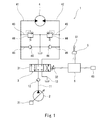
- FIG. 1 is a schematic configuration diagram of a hydraulic drive system for a construction machine according to a first embodiment of the present invention. It is a side view of the hydraulic excavator which is an example of a construction machine.
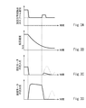
- 3A to 3D are graphs at the time of turning stop in the first embodiment, FIG. 3A shows a change with time of the spool displacement of the turning direction switching valve, FIG. 3B shows a change with time of the turning speed, and FIG. FIG. 3D shows the change over time in the outflow pressure of the swing motor.
- FIGS. 5A to 5D are graphs at the time of turning stop in the second embodiment, FIG. 5A shows a change with time of the spool displacement of the turning direction switching valve, FIG. 5B shows a change with time of the turning speed, and FIG. FIG. 5D shows the change with time of the outflow pressure of the swing motor.
- FIG. 1 shows a hydraulic drive system 1 for a construction machine according to a first embodiment of the present invention
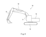
- FIG. 2 shows a construction machine 10 on which the hydraulic drive system 1 is mounted.
- the construction machine 10 shown in FIG. 2 is a hydraulic excavator, but the present invention is also applicable to other construction machines such as a hydraulic crane.
- the construction machine 10 shown in FIG. 2 is self-propelled and includes a traveling body 75 and a revolving body 76 that is supported by the traveling body 75 so as to be able to swivel.
- the revolving body 76 is provided with a cabin including a driver's seat and is connected to a boom. An arm is connected to the tip of the boom, and a bucket is connected to the tip of the arm.
- the construction machine 10 may not be self-propelled.
- the hydraulic drive system 1 includes a boom cylinder 71, an arm cylinder 72, and a bucket cylinder 73 shown in FIG. 2 as hydraulic actuators, and also includes a turning motor 4 shown in FIG. 1 and a pair of left and right traveling motors (not shown).
- the turning motor 4 turns the turning body 76.
- the hydraulic drive system 1 includes a pump 2 for supplying hydraulic fluid to those actuators as shown in FIG. In FIG. 1, hydraulic actuators other than the turning motor 4 are omitted for simplification of the drawing.
- the hydraulic drive system 1 includes a turning direction switching valve 3 that controls supply and discharge of hydraulic fluid to the turning motor 4, a turning operation device 5 that includes an operation lever 51 that receives a turning operation, and a control device 6.
- the pump 2 is a variable displacement pump whose tilt angle can be changed.
- the pump 2 may be a swash plate pump or an oblique shaft pump.
- the tilt angle of the pump 2 is adjusted by the regulator 21.
- the regulator 21 may be driven by an electric signal or may be driven by a pilot pressure.
- the pump 2 is connected to the turning direction switching valve 3 by a pump line 11.
- a check valve 12 is provided in the pump line 11.
- the discharge pressure of the pump 2 is kept below the first upper limit pressure by a relief valve (not shown).
- the turning direction switching valve 3 is connected to the tank by a tank line 13.
- the turning direction switching valve 3 is connected to the turning motor 4 by a pair of supply / discharge lines 41, 42.
- a relief line 43 branches from each of the supply / discharge lines 41 and 42, and the relief line 43 is connected to the tank.
- Each relief line 43 is provided with a relief valve 44. That is, the pressure of each of the supply / discharge lines 41 and 42 is kept below the second upper limit pressure by the relief valve 44. Note that the second upper limit pressure may be equal to or different from the first upper limit pressure described above.
- each of the supply / discharge lines 41 and 42 is connected to a tank by a makeup line 45.
- Each makeup line 45 is provided with a check valve 46 that allows the flow toward the supply / discharge line (41 or 42) but prohibits the reverse flow.
- the makeup line (41 or 42) plays a role of causing the working fluid to flow directly from the tank into the supply / discharge line on the supply side during turning deceleration.
- the turning direction switching valve 3 has a neutral position where both the supply / discharge lines 41 and 42 are blocked, and a first operating position (the communication line 41 communicates with the pump line 11 and the supply / discharge line 42 communicates with the tank line 13 ( 1 is shifted to the second operating position (the right position in FIG. 1) where the supply / discharge line 42 communicates with the pump line 11 and the supply / discharge line 41 communicates with the tank line 13.
- the turning direction switching valve 3 is driven by an electric signal.
- the turning direction switching valve 3 includes a spool 31 and a drive unit 32 that receives the command current and drives the spool 31.
- the drive unit 32 may be composed of a pair of electromagnetic proportional valves that output secondary pressure acting on the spool 31 in opposite directions, and includes an electric motor and a ball screw connected to the spool 31.
- a linear motion mechanism may be used.
- the turning direction switching valve 3 has a larger opening degree as the command current supplied to the drive unit 32 increases, and increases the amount of hydraulic fluid supplied to the turning motor 4 and the amount of hydraulic fluid discharged from the turning motor 4.
- the turning operation device 5 outputs a turning operation signal (right turning operation signal or left turning operation signal) corresponding to the tilt angle (turning operation amount) of the operation lever 51. That is, the turning operation signal output from the turning operation device 5 increases as the tilt angle of the operation lever 51 increases.
- the turning operation device 5 is an electric joystick that outputs an electric signal as a turning operation signal.
- the turning operation signal (electric signal) output from the turning operation device 5 is input to the control device 6.
- the control device 6 has a memory such as a ROM and a RAM and a CPU, and a program stored in the ROM is executed by the CPU.
- the control device 6 sends a larger command current to the drive unit 32 of the turning direction switching valve 3 as the turning operation signal becomes larger. Thereby, the spool 31 of the turning direction switching valve 3 moves greatly as the tilt angle of the operation lever 51 of the turning operation device 5 increases.
- the control device 6 is electrically connected to a speed detector 65 that detects the turning speed of the turning body 76.
- the speed detector 65 is a gyro sensor provided in the revolving body 76, for example.
- the speed detector 65 may be, for example, an encoder or a revolver attached to the turning motor 4.
- the control device 6 controls the turning direction switching valve 3 so as to prevent a swinging return phenomenon when the turning is stopped. Specifically, the control device 6 sets the command current supplied to the drive unit 32 of the turning direction switching valve 3 to zero when the operation lever 51 of the turning operation device 5 is returned to the neutral state. Thereby, as shown to FIG. 3A, the turning direction switching valve 3 shifts from an operation position (a 1st operation position or a 2nd operation position) to a neutral position. As a result, the inflow pressure of the swing motor 4 (pressure on the supply-side supply / discharge line) becomes zero as shown in FIG. 3C, and the outflow pressure of the swing motor 4 (pressure on the discharge-side supply / discharge line as shown in FIG. 3D). ) Will rise.
- the control device 6 communicates the supply / discharge line on the discharge side with the tank line 13 from the neutral position of the turning direction switching valve 3.
- the command current is supplied to the drive unit 32 of the turning direction switching valve 3 so as to shift to the operating position. Thereby, the outflow pressure of the turning motor 4 is reduced to zero.
- the control device 6 causes the turning direction switching valve 3 to move from the operating position to the neutral position.
- a command current is supplied to the drive unit 32 of the turning direction switching valve 3 so as to shift. Thereby, the revolving structure 76 stops completely.
- the first threshold value ⁇ and the second threshold value ⁇ described above may be fixed values determined in advance, or may be calculated each time by multiplying the turning speed before turning stop by a coefficient. For example, when the first threshold value ⁇ and the second threshold value ⁇ are fixed values, the first threshold value ⁇ is 5 to 20% of the maximum speed, and the second threshold value ⁇ is 1 to 10% of the maximum speed.
- the turning direction switching valve 3 is shifted to the operating position if the turning speed falls below the first threshold value ⁇ .
- the pressure in the supply / discharge line on the discharge side rapidly decreases, so that the differential pressure between the supply / discharge lines 41 and 42 is reduced, and the reversal of the revolving structure 76 is prevented. Therefore, it is possible to prevent the swinging back phenomenon when stopping turning without using the reverse prevention valve.
- FIGS. 3C and 3D a change in pressure when a swing back phenomenon occurs without performing the control of the present embodiment is indicated by a broken line.
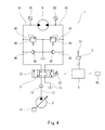
- a pair of pressure sensors 61 and 62 may be provided on the supply / discharge lines 41 and 42.
- One of the pressure sensors 61 and 62 detects the inflow pressure of the swing motor 4, and the other of the pressure sensors 61 and 62 detects the outflow pressure of the swing motor 4.
- the opening degree of the turning direction switching valve 3 (the displacement of the spool 31). ) was constant.
- the pressure sensors 61 and 62 when the turning direction switching valve 3 is shifted to the operating position after the operation lever 51 of the turning operation device 5 is returned to the neutral state, the turning direction switching valve 3 is The opening may be controlled according to the differential pressure between the inflow pressure and the outflow pressure of the swing motor 4 detected by the pressure sensors 61 and 62. According to this configuration, the differential pressure between the supply / discharge lines 41 and 42 can be minimized.
- the control device 6 controls the turning direction switching valve 3 so that the turning direction switching valve 3 shifts the discharge side supply / discharge line from the neutral position to the operating position communicating with the tank line 13.
- a command current may be supplied to the drive unit 32.
- the first threshold value ⁇ (or ⁇ ′) is a threshold value ⁇ 1 for a turning operation alone and a threshold value for a turning combined operation in which the turning operation is performed simultaneously with another operation (for example, a boom operation, an arm operation, or a bucket operation). It may be divided into ⁇ 2 ( ⁇ 1).
- the control device 6 controls the turning direction switching valve 3 so as to prevent a swinging back phenomenon when turning is stopped. Specifically, the control device 6 sets the command current supplied to the drive unit 32 of the turning direction switching valve 3 to zero when the operation lever 51 of the turning operation device 5 is returned to the neutral state. Thereby, as shown to FIG. 5A, the turning direction switching valve 3 shifts from an operation position (a 1st operation position or a 2nd operation position) to a neutral position. As a result, the inflow pressure of the swing motor 4 (pressure on the supply side supply / discharge line) becomes zero as shown in FIG. 5C, and the outflow pressure of the swing motor 4 (pressure on the discharge side supply / discharge line shows) as shown in FIG. 5D. ) Will rise.
- the control device 6 When the turning direction switching valve 3 is shifted to the neutral position, the turning speed of the turning body 76 gradually decreases due to the braking action of the relief valve 44 on the discharge side, as shown in FIG. 5B.
- the control device 6 When the turning speed of the turning body 76 detected by the speed detector 65 falls below the threshold value ⁇ , the control device 6 operates to connect the supply / discharge line on the discharge side to the tank line 13 from the neutral position of the turning direction switching valve 3. A command current is supplied to the drive unit 32 of the turning direction switching valve 3 so as to shift to the position. Thereby, the outflow pressure of the turning motor 4 is reduced to zero.
- the threshold value ⁇ may be a predetermined fixed value or may be calculated each time by multiplying the turning speed before turning stop by a coefficient.
- the control device 6 controls the turning direction switching valve 3 so that the opening degree of the turning direction switching valve 3 corresponds to the pressure difference between the inflow pressure and the outflow pressure of the turning motor 4 detected by the pressure sensors 61 and 62.
- the command current is supplied to the drive unit 32 of More specifically, the control device 6 increases the opening degree of the turning direction switching valve 3 as the differential pressure between the inflow pressure and the outflow pressure of the turning motor 4 increases.
- the control device 6 When the inflow pressure becomes higher than the outflow pressure, the turning direction switching valve 3 is controlled so that the turning direction switching valve 3 shifts the supply / discharge line on the supply side to the operating position communicating with the tank line 13. That is, the turning direction switching valve 3 switches from the first operating position to the second operating position, or from the second operating position to the first operating position.
- the turning direction switching valve 3 when the turning is stopped, the turning direction switching valve 3 is shifted to the operating position if the turning speed falls below the threshold value ⁇ .
- the pressure in the supply / discharge line on the discharge side rapidly decreases, so that the differential pressure between the supply / discharge lines 41 and 42 is reduced, and the reversal of the revolving structure 76 is prevented. Therefore, it is possible to prevent the swinging back phenomenon when stopping turning without using the reverse prevention valve.
- the opening degree when the turning direction switching valve 3 is shifted to the operating position, the opening degree depends on the differential pressure between the inflow pressure and the outflow pressure of the turning motor 4. The differential pressure can be minimized.
- the operating position of the turning direction switching valve 3 is switched, so even if the turning body 76 is reversed when the turning is stopped, Subsequent further inversion can be prevented.
- the turning direction switching valve 3 when the turning direction switching valve 3 is shifted to the operating position after the operation lever 51 of the turning operation device 5 is returned to the neutral state, the turning is made according to the rate of change of the inflow pressure and / or the outflow pressure of the turning motor 4.
- the opening degree of the direction switching valve 3 may be adjusted.
- the threshold value ⁇ (or ⁇ ′) includes a threshold value ⁇ 1 for a single turning operation and a threshold value ⁇ 2 for a turning combined operation in which the turning operation is performed simultaneously with another operation (for example, a boom operation, an arm operation, or a bucket operation). ⁇ 1).
- the turning operation device 5 is not necessarily an electric joystick, but may be a pilot operation valve that outputs a pilot pressure as a turning operation signal.
- the pilot pressure output from the turning operation device 5 is detected by the pressure sensor and input to the control device 6.
Landscapes
- Engineering & Computer Science (AREA)
- General Engineering & Computer Science (AREA)
- Mining & Mineral Resources (AREA)
- Civil Engineering (AREA)
- Structural Engineering (AREA)
- Physics & Mathematics (AREA)
- Fluid Mechanics (AREA)
- Mechanical Engineering (AREA)
- Fluid-Pressure Circuits (AREA)
- Operation Control Of Excavators (AREA)
Abstract
Description
図1に、本発明の第1実施形態に係る建設機械の油圧駆動システム1を示し、図2に、その油圧駆動システム1が搭載された建設機械10を示す。図2に示す建設機械10は油圧ショベルであるが、本発明は、油圧クレーンなどの他の建設機械にも適用可能である。
シフトするように、旋回方向切換弁3の駆動部32へ指令電流を送給する。これにより、旋回体76が完全に停止する。
図4に示すように、給排ライン41,42には一対の圧力センサ61,62が設けられてもよい。圧力センサ61,62の一方は旋回モータ4の流入圧を検出し、圧力センサ61,62の他方は旋回モータ4の流出圧を検出する。
次に、図5A~5Dを参照して、本発明の第2実施形態に係る建設機械の油圧駆動システムを説明する。第2実施形態の油圧駆動システムの構成は、図4に示す第1実施形態の変形例と同様である。
旋回操作装置5の操作レバー51が中立状態に戻された後は、圧力センサ61,62の一方で検出される旋回モータ4の流出圧が閾値γ’を下回ったときに、制御装置6が、旋回方向切換弁3が中立位置から排出側の給排ラインをタンクライン13と連通する作動位置へシフトするように、旋回方向切換弁3の駆動部32へ指令電流を送給してもよい。この構成でも、前記実施形態と同様の効果を得ることができる。この場合、速度検出器65は省略されてもよい。
本発明は上述した実施形態に限定されるものではなく、本発明の要旨を逸脱しない範囲で種々の変形が可能である。
11 供給ライン
13 タンクライン
3 旋回方向切換弁
31 スプール
32 駆動部
4 旋回モータ
5 旋回操作装置
51 操作レバー
6 制御装置
61,62 圧力センサ
65 速度検出器
Claims (5)
- 旋回体を旋回させる旋回モータと、
操作レバーを含み、前記操作レバーの傾倒角に応じた旋回操作信号を出力する旋回操作装置と、
一対の給排ラインにより前記旋回モータと接続された旋回方向切換弁であって、スプールおよび指令電流を受けて前記スプールを駆動する駆動部を含み、前記一対の給排ラインをブロックする中立位置と、前記一対の給排ラインの一方をポンプライン、他方をタンクラインと連通する作動位置との間でシフトする旋回方向切換弁と、
前記旋回操作信号が大きくなるほど大きな指令電流を前記旋回方向切換弁へ送給する制御装置と、
前記旋回体の旋回速度を検出する速度検出器と、を備え、
前記制御装置は、前記旋回操作装置の操作レバーが中立状態に戻された場合、前記速度検出器で検出される旋回速度が第1閾値を下回ったときに、前記旋回方向切換弁が中立位置から排出側の給排ラインをタンクラインと連通する作動位置へシフトし、前記速度検出器で検出される旋回速度が前記第1閾値よりも小さな第2閾値を下回ったときに、前記旋回方向切換弁が作動位置から中立位置へシフトするように、前記旋回方向切換弁を制御する、建設機械の油圧駆動システム。 - 旋回体を旋回させる旋回モータと、
操作レバーを含み、前記操作レバーの傾倒角に応じた旋回操作信号を出力する旋回操作装置と、
一対の給排ラインにより前記旋回モータと接続された旋回方向切換弁であって、スプールおよび指令電流を受けて前記スプールを駆動する駆動部を含み、前記一対の給排ラインをブロックする中立位置と、前記一対の給排ラインの一方をポンプライン、他方をタンクラインと連通する作動位置との間でシフトする旋回方向切換弁と、
前記旋回操作信号が大きくなるほど大きな指令電流を前記旋回方向切換弁へ送給する制御装置と、
前記旋回体の旋回速度を検出する速度検出器と、
前記旋回モータの流入圧および流出圧を検出する一対の圧力センサと、を備え、
前記制御装置は、前記旋回操作装置の操作レバーが中立状態に戻された場合、前記一対の圧力センサの一方で検出される前記旋回モータの流出圧が第1閾値を下回ったときに、前記旋回方向切換弁が中立位置から排出側の給排ラインをタンクラインと連通する作動位置へシフトし、前記速度検出器で検出される旋回速度が第2閾値を下回ったときに、前記旋回方向切換弁が作動位置から中立位置へシフトするように、前記旋回方向切換弁を制御する、建設機械の油圧駆動システム。 - 旋回体を旋回させる旋回モータと、
操作レバーを含み、前記操作レバーの傾倒角に応じた旋回操作信号を出力する旋回操作装置と、
一対の給排ラインにより前記旋回モータと接続された旋回方向切換弁であって、スプールおよび指令電流を受けて前記スプールを駆動する駆動部を含み、前記一対の給排ラインをブロックする中立位置と、前記一対の給排ラインの一方をポンプライン、他方をタンクラインと連通する作動位置との間でシフトする旋回方向切換弁と、
前記旋回操作信号が大きくなるほど大きな指令電流を前記旋回方向切換弁へ送給する制御装置と、
前記旋回体の旋回速度を検出する速度検出器と、
前記旋回モータの流入圧および流出圧を検出する一対の圧力センサと、を備え、
前記制御装置は、前記旋回操作装置の操作レバーが中立状態に戻された場合、前記速度検出器で検出される旋回速度が閾値を下回ったときに、前記旋回方向切換弁が中立位置から排出側の給排ラインをタンクラインと連通する作動位置へシフトし、その後は前記旋回方向切換弁が前記一対の圧力センサで検出される旋回モータの流入圧と流出圧との差圧に応じた開度となるように、前記旋回方向切換弁を制御する、建設機械の油圧駆動システム。 - 旋回体を旋回させる旋回モータと、
操作レバーを含み、前記操作レバーの傾倒角に応じた旋回操作信号を出力する旋回操作装置と、
一対の給排ラインにより前記旋回モータと接続された旋回方向切換弁であって、スプールおよび指令電流を受けて前記スプールを駆動する駆動部を含み、前記一対の給排ラインをブロックする中立位置と、前記一対の給排ラインの一方をポンプライン、他方をタンクラインと連通する作動位置との間でシフトする旋回方向切換弁と、
前記旋回操作信号が大きくなるほど大きな指令電流を前記旋回方向切換弁へ送給する制御装置と、
前記旋回モータの流入圧および流出圧を検出する一対の圧力センサと、を備え、
前記制御装置は、前記旋回操作装置の操作レバーが中立状態に戻された場合、前記一対の圧力センサの一方で検出される前記旋回モータの流出圧が閾値を下回ったときに、前記旋回方向切換弁が中立位置から排出側の給排ラインをタンクラインと連通する作動位置へシフトし、その後は前記旋回方向切換弁が前記一対の圧力センサで検出される旋回モータの流入圧と流出圧との差圧に応じた開度となるように、前記旋回方向切換弁を制御する、建設機械の油圧駆動システム。 - 前記制御装置は、前記旋回操作装置の操作レバーが中立状態に戻され、前記旋回方向切換弁が排出側の給排ラインをタンクラインと連通する作動位置へシフトした後に、前記旋回モータの流入圧が流出圧よりも高くなったときは、前記旋回方向切換弁が供給側の給排ラインをタンクラインと連通する作動位置へシフトするように、前記旋回方向切換弁を制御する、請求項3または4に記載の建設機械の油圧駆動システム。
Priority Applications (3)
| Application Number | Priority Date | Filing Date | Title |
|---|---|---|---|
| PCT/JP2018/019514 WO2019224877A1 (ja) | 2018-05-21 | 2018-05-21 | 建設機械の油圧駆動システム |
| GB2017037.9A GB2585813B (en) | 2018-05-21 | 2018-05-21 | Hydraulic drive system of construction machine |
| CN201880092456.1A CN111936751B (zh) | 2018-05-21 | 2018-05-21 | 建筑机械的油压驱动系统 |
Applications Claiming Priority (1)
| Application Number | Priority Date | Filing Date | Title |
|---|---|---|---|
| PCT/JP2018/019514 WO2019224877A1 (ja) | 2018-05-21 | 2018-05-21 | 建設機械の油圧駆動システム |
Publications (1)
| Publication Number | Publication Date |
|---|---|
| WO2019224877A1 true WO2019224877A1 (ja) | 2019-11-28 |
Family
ID=68616648
Family Applications (1)
| Application Number | Title | Priority Date | Filing Date |
|---|---|---|---|
| PCT/JP2018/019514 Ceased WO2019224877A1 (ja) | 2018-05-21 | 2018-05-21 | 建設機械の油圧駆動システム |
Country Status (3)
| Country | Link |
|---|---|
| CN (1) | CN111936751B (ja) |
| GB (1) | GB2585813B (ja) |
| WO (1) | WO2019224877A1 (ja) |
Families Citing this family (1)
| Publication number | Priority date | Publication date | Assignee | Title |
|---|---|---|---|---|
| FR3128254B1 (fr) * | 2021-10-15 | 2025-03-28 | Bosch Gmbh Robert | Circuit hydraulique équipé d’un système de commande d’un composant hydraulique |
Citations (4)
| Publication number | Priority date | Publication date | Assignee | Title |
|---|---|---|---|---|
| JPH02261907A (ja) * | 1989-03-31 | 1990-10-24 | Nippon Air Brake Co Ltd | 油圧ショベル等の旋回制御装置 |
| JPH0738701U (ja) * | 1993-12-14 | 1995-07-14 | 新キャタピラー三菱株式会社 | 油圧モータの油圧制御回路装置 |
| JPH09242708A (ja) * | 1996-03-11 | 1997-09-16 | Kobe Steel Ltd | 油圧アクチュエータの速度制御装置 |
| JPH10246205A (ja) * | 1997-03-05 | 1998-09-14 | Shin Caterpillar Mitsubishi Ltd | 油圧モータの油圧制御回路装置 |
Family Cites Families (2)
| Publication number | Priority date | Publication date | Assignee | Title |
|---|---|---|---|---|
| WO2012150652A1 (ja) * | 2011-05-02 | 2012-11-08 | コベルコ建機株式会社 | 旋回式作業機械 |
| JP5783184B2 (ja) * | 2013-01-10 | 2015-09-24 | コベルコ建機株式会社 | 建設機械 |
-
2018
- 2018-05-21 GB GB2017037.9A patent/GB2585813B/en active Active
- 2018-05-21 CN CN201880092456.1A patent/CN111936751B/zh active Active
- 2018-05-21 WO PCT/JP2018/019514 patent/WO2019224877A1/ja not_active Ceased
Patent Citations (4)
| Publication number | Priority date | Publication date | Assignee | Title |
|---|---|---|---|---|
| JPH02261907A (ja) * | 1989-03-31 | 1990-10-24 | Nippon Air Brake Co Ltd | 油圧ショベル等の旋回制御装置 |
| JPH0738701U (ja) * | 1993-12-14 | 1995-07-14 | 新キャタピラー三菱株式会社 | 油圧モータの油圧制御回路装置 |
| JPH09242708A (ja) * | 1996-03-11 | 1997-09-16 | Kobe Steel Ltd | 油圧アクチュエータの速度制御装置 |
| JPH10246205A (ja) * | 1997-03-05 | 1998-09-14 | Shin Caterpillar Mitsubishi Ltd | 油圧モータの油圧制御回路装置 |
Also Published As
| Publication number | Publication date |
|---|---|
| GB202017037D0 (en) | 2020-12-09 |
| GB2585813A (en) | 2021-01-20 |
| CN111936751B (zh) | 2023-08-01 |
| GB2585813B (en) | 2022-10-19 |
| CN111936751A (zh) | 2020-11-13 |
Similar Documents
| Publication | Publication Date | Title |
|---|---|---|
| JP6335093B2 (ja) | 建設機械の油圧駆動システム | |
| US10422109B2 (en) | Shovel and method of controlling shovel | |
| JP5965502B1 (ja) | 建設機械の油圧駆動システム | |
| JP6852145B2 (ja) | ショベル | |
| US11162242B2 (en) | Slewing-type work machine | |
| CN111226045B (zh) | 工程机械的油压驱动系统 | |
| KR102571723B1 (ko) | 건설기계 | |
| JP6915042B2 (ja) | ショベル | |
| CN109790857B (zh) | 建筑机械的油压驱动系统 | |
| JP7392819B2 (ja) | 作業機械の旋回駆動装置 | |
| JP6915436B2 (ja) | 旋回式油圧作業機械 | |
| JP2013234683A (ja) | 作業機械の旋回装置並びにその作業機械 | |
| WO2019004156A1 (ja) | 油圧駆動システム | |
| JP6901875B2 (ja) | 建設機械の油圧駆動システム | |
| WO2016092809A1 (ja) | 建設機械の油圧駆動システム | |
| JP6799480B2 (ja) | 油圧システム | |
| CN111936751B (zh) | 建筑机械的油压驱动系统 | |
| JP6955349B2 (ja) | 建設機械の油圧駆動システム | |
| WO2024071389A1 (ja) | 作業機械 | |
| JP2010150773A (ja) | 建設機械の油圧駆動装置 |
Legal Events
| Date | Code | Title | Description |
|---|---|---|---|
| 121 | Ep: the epo has been informed by wipo that ep was designated in this application |
Ref document number: 18920070 Country of ref document: EP Kind code of ref document: A1 |
|
| ENP | Entry into the national phase |
Ref document number: 202017037 Country of ref document: GB Kind code of ref document: A Free format text: PCT FILING DATE = 20180521 |
|
| WWE | Wipo information: entry into national phase |
Ref document number: 2017037.9 Country of ref document: GB |
|
| NENP | Non-entry into the national phase |
Ref country code: DE |
|
| 122 | Ep: pct application non-entry in european phase |
Ref document number: 18920070 Country of ref document: EP Kind code of ref document: A1 |
|
| NENP | Non-entry into the national phase |
Ref country code: JP |
|
| WWG | Wipo information: grant in national office |
Ref document number: 2017037.9 Country of ref document: GB |