WO2019220596A1 - 転送装置、転送方法および転送プログラム - Google Patents
転送装置、転送方法および転送プログラム Download PDFInfo
- Publication number
- WO2019220596A1 WO2019220596A1 PCT/JP2018/019141 JP2018019141W WO2019220596A1 WO 2019220596 A1 WO2019220596 A1 WO 2019220596A1 JP 2018019141 W JP2018019141 W JP 2018019141W WO 2019220596 A1 WO2019220596 A1 WO 2019220596A1
- Authority
- WO
- WIPO (PCT)
- Prior art keywords
- packet
- transfer
- read
- unit
- determination
- Prior art date
- Legal status (The legal status is an assumption and is not a legal conclusion. Google has not performed a legal analysis and makes no representation as to the accuracy of the status listed.)
- Ceased
Links
Images





Classifications
-
- H—ELECTRICITY
- H04—ELECTRIC COMMUNICATION TECHNIQUE
- H04L—TRANSMISSION OF DIGITAL INFORMATION, e.g. TELEGRAPHIC COMMUNICATION
- H04L47/00—Traffic control in data switching networks
- H04L47/10—Flow control; Congestion control
- H04L47/32—Flow control; Congestion control by discarding or delaying data units, e.g. packets or frames
-
- H—ELECTRICITY
- H04—ELECTRIC COMMUNICATION TECHNIQUE
- H04N—PICTORIAL COMMUNICATION, e.g. TELEVISION
- H04N21/00—Selective content distribution, e.g. interactive television or video on demand [VOD]
- H04N21/60—Network structure or processes for video distribution between server and client or between remote clients; Control signalling between clients, server and network components; Transmission of management data between server and client, e.g. sending from server to client commands for recording incoming content stream; Communication details between server and client
- H04N21/61—Network physical structure; Signal processing
- H04N21/6106—Network physical structure; Signal processing specially adapted to the downstream path of the transmission network
- H04N21/6125—Network physical structure; Signal processing specially adapted to the downstream path of the transmission network involving transmission via Internet
Definitions
- the present invention relates to a transfer device, a transfer method, and a transfer program.
- the present invention relates to a transfer apparatus, a transfer method, and a transfer program that perform broadcast communication via a plurality of transfer networks.
- the transmission side switch device gives a unique broadcast control tag including the device ID of the transmission side switch device, the sequence number indicating the continuity of the packet, and the status information of the transmission side switch device to the packet to be transmitted. To do. ID is an abbreviation for Identifier. The sequence number may be described as SN. Further, the transmission side switch device attaches a broadcast control tag to the packet, and then copies and transmits the same packet to a plurality of layer 2 transfer networks connected to the transmission side switch device.
- the receiving-side switch device reads out the received packet from the buffer, refers to the content of the broadcast control tag attached to the read packet, and refers to the previously received sequence number held for each ID and the broadcast control referred to Compare the sequence numbers of tags. As a result of the comparison, if the referenced sequence number is large, it is determined that the packet has not been received, and if the referenced sequence number is small or the same, it is determined that the packet has already been received. The receiving side switching device selects if the packet has not been received, and discards it if it has already been received.
- the same packet can be received from a plurality of layer 2 transport networks, and the previously received packet can be selected by the receiving side switch.
- the receiving side switch As a result, even if a failure occurs in one layer 2 transport network among a plurality of layer 2 transport networks and reception of packets is interrupted, if other layer 2 communication networks remain, no interruption occurs. Communication can be continued by disconnection.
- the receiving side selects or discards a packet while intentionally delaying a received packet from one system. Normally, a packet from a non-delayed system, that is, a non-delayed system is selected. Then, the system from which the delay is inserted, that is, the packet from the delay system is discarded.
- the delay system is switched, and a non-delay system after switching the delay system, that is, a packet from the original delay system is selected. Even when the packet is not received from the non-delay system, the packet input to the delay system can be selected, so that no packet loss occurs.
- packets accumulated in the delay insertion buffer are read out at a higher speed than usual in order to eliminate the delay amount that has been inserted. For example, reading is performed at double speed. Then, the packet having the sequence number received in the original non-delay system is discarded, and the packet having the sequence number not received from the original non-delay system is selected.
- the buffer reading method in delay system switching in Patent Document 1 is possible only when the output line speed is twice or more higher than the input line speed.
- the buffer read system disclosed in Patent Document 1 cannot be adopted. Therefore, in the communication system of Patent Document 1 in which the input / output line speed is constant, the received packet stored in the buffer for delay insertion is read at the same speed as the input speed. Therefore, there is a problem that the delay amount inserted in the delay system cannot be eliminated and it takes time to process the packet.
- An object of the present invention is to shorten the packet processing time by skipping packets to be discarded.
- the transfer device is a transfer device included in a communication system in which each transfer device of a plurality of transfer devices broadcasts via a plurality of transfer networks.
- a packet with a broadcast control tag including a packet identifier for identifying the packet and a sequence number indicating the continuity of the packet is acquired via each of the plurality of transfer networks, and the packet is stored in the buffer.
- a tag extraction unit that stores and extracts information of the broadcast control tag from the packet;
- a packet determination unit that acquires information on the broadcast control tag extracted by the tag extraction unit and determines whether to select or discard the packet based on the packet identifier and the sequence number;
- a read determining unit that determines whether to read or skip the packet stored in the buffer based on a determination result by the packet determining unit.
- the read determination unit determines whether to read or skip the packet stored in the buffer based on the determination result of whether the packet determination unit selects or discards the packet. Therefore, according to the transfer apparatus of the present invention, packets to be discarded can be skipped without being read from the buffer, and the packet processing time can be shortened.
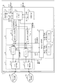
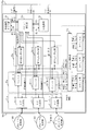
- FIG. 1 is a configuration diagram of a communication system according to Embodiment 1.
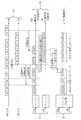
- FIG. FIG. 3 is a detailed configuration diagram of a receiving unit of the transfer apparatus according to the first embodiment.
- FIG. 3 is a hardware configuration diagram of the transfer apparatus according to the first embodiment.
- 5 is a flowchart showing the operation of the transfer device on the reception side according to the first embodiment.
- FIG. 6 is a diagram showing a comparative example to be compared with the transfer process according to the first embodiment.
- FIG. 6 is a diagram illustrating an example of transfer processing according to the first embodiment.
- FIG. 6 is a configuration diagram of a transfer device according to a modification of the first embodiment.
- FIG. 3 is a configuration diagram of a communication system according to a second embodiment.
- FIG. 4 is a detailed configuration diagram of a receiving unit of a transfer device according to a second embodiment.
- FIG. 10 is a configuration diagram of a communication system according to a modification of the second embodiment.
- Embodiment 1 FIG. *** Explanation of configuration *** The configuration of a communication system 500 according to the present embodiment will be described using FIG.
- the communication system 500 includes a plurality of transfer devices 100.
- 1 includes transfer devices 11, 12,..., 1m as a plurality of transfer devices 100.
- m is an integer of 2 or more.
- all or part of the transfer devices 11, 12,..., 1 m are described as the transfer device 100.
- the transfer devices of the two transfer devices perform broadcast communication via the two transfer networks 30.
- the transfer devices 11, 12,..., 1m are connected by a plurality of layer 2 transfer networks.
- the plurality of layer 2 transport networks include a 0-system layer 2 transport network 300 and a 1-system layer 2 transport network 301.
- the 0-system layer 2 transport network 300 and the 1-system layer 2 transport network 301 are examples of a plurality of transport networks 30.
- the communication system 500 is provided between the transmission terminal device and the reception terminal device, and transfers a packet received from the transmission terminal device to the reception terminal device.
- a packet is broadcast from the transfer device 11 to the transfer device 1m via a plurality of layer 2 transfer networks.
- the configuration of the transmission unit 10 is shown.
- the configuration of the receiving unit 20 is shown.
- the transfer apparatuses 11 to 1 m generally include both a transmission unit 10 that performs packet transmission processing and a reception unit 20 that performs packet reception processing. That is, the transfer device 11 also includes a receiving unit similar to the transfer device 1m, and the transfer device 1m also includes a transmission unit similar to the transfer device 11. That is, the transfer device 12 to the transfer device 1 (m ⁇ 1) have the same configuration as the transfer device 11 and the transfer device 1m.
- the transfer device 1m When the transfer device 100 on the receiving side, that is, the transfer device 1m receives the packet, it extracts the broadcast control tag information of the packet in advance. Then, before starting to read out the packet stored in the delay insertion buffer, the transfer device 1m determines whether to select or discard the packet based on the extracted broadcast control tag information. When the determination result regarding the selective discard of the packet is selected, the transfer device 1m reads out one packet of the selected packet from the buffer. Further, when the determination result is discard, one packet of the discard packet is skipped from the buffer. That is, in the transfer device 1m, when the determination result is discarded, the packet is skipped without being read from the delay insertion buffer. As a result, reading from the buffer for delay insertion is performed faster than the line speed.
- the transfer device 100 includes a transmission unit 10 and a reception unit 20 as functional elements.
- the transmission unit 10 includes a layer 2 switch unit 111, a tag insertion unit 112, a copy unit 113, an SN generation unit 114, and a transmission source holding unit 115.
- the reception unit 20 includes a tag extraction unit 21, a delay insertion unit 22, a packet determination unit 23, a reception interval timer unit 24, an SN holding unit 25, a tag deletion unit 26, a layer 2 switch unit 27, and a buffer 29.
- the functions of the layer 2 switch unit 111, the tag insertion unit 112, the copy unit 113, and the SN generation unit 114 of the transmission unit 10 are also referred to as functions of the transmission unit 10.
- the functions of the tag extraction unit 21, the delay insertion unit 22, the packet determination unit 23, the reception interval timer unit 24, the tag deletion unit 26, and the layer 2 switch unit 27 of the reception unit 20 are also referred to as functions of the reception unit 20.
- a packet transmitted from the transmission apparatus 100 on the transmission side is provided with a broadcast control tag including an ID that is a packet identifier for identifying the packet and a sequence number indicating the continuity of the packet.
- the ID is, for example, an identifier that identifies the transfer device that is the transmission source of the packet.
- the tag extraction unit 21 acquires a packet with a broadcast control tag from the layer 2 transport network, stores the packet in the buffer 29, and extracts information on the broadcast control tag from the packet.
- the tag extraction unit 21 includes tag extraction units 31-0 and 31-1 each corresponding to each of the layer 2 transport networks.
- the tag extraction unit 31-0 extracts the broadcast control tag information for the packet from the 0-system layer 2 transport network 300, and notifies the packet determination unit 23 of the selective discard determination request.
- the transfer network is a system for inserting a delay, a fixed delay amount is inserted in the time from the broadcast tag extraction to the selective discard determination request.
- the tag extraction unit 31-1 extracts the broadcast control tag information for the packet from the 1-system layer 2 transport network 301, and notifies the packet determination unit 23 of the selective discard determination request.
- the selection discard determination request includes information on the broadcast control tag.
- the tag extraction unit 21 is also referred to as a broadcast control tag information extraction unit.
- the delay insertion unit 22 includes a read control unit 33, count units 35-0 and 35-1, and read determination units 34-0 and 34-1. Note that a component having a suffix “ ⁇ 0” after the symbol corresponds to a packet from the 0-system layer 2 transport network 300. A component having a suffix “ ⁇ 1” after the symbol corresponds to a packet from the 1-system layer 2 transport network 301. Since the delay insertion unit 22 inserts a delay into a packet received from one of the two layer 2 transport networks and processes the packet, it is also referred to as a one-system delay insertion unit.
- the buffer 29 includes buffers 32-0 and 32-1 for each system of the transfer network. Packets are stored in the buffers 32-0 and 32-1, respectively. When the packet is stored, the buffers 32-0 and 32-1 notify the read control unit 33 of the arrival signal. When the read decision units 34-0 and 34-1 determine that the buffers 32-0 and 32-1 are to read packets, the buffers 32-0 and 32-1 advance the read pointer of the buffer and realize reading of one packet. Further, when the read decision units 34-0 and 34-1 decide to skip the packet, the buffers 32-0 and 32-1 advance the packet read pointer by one packet to be discarded. Skip.
- the read determination units 34-0 and 34-1 determine whether to read or skip the packets stored in the buffers 32-0 and 32-1, based on the determination result 231 by the packet determination unit 23.
- the buffer 29, that is, the buffers 32-0 and 32-1, are delay insertion buffers, and are also referred to as delay insertion buffers.
- the read control unit 33 notifies the counting units 35-0 and 35-1 of the arrival presence signal notified from the buffers 32-0 and 32-1.
- the count unit 35-0 clears the counter.
- the counting unit 35-0 counts up the counter.
- the timing at which the counting unit 35-0 counts up is, for example, every operation clock.
- the count unit 35-0 outputs an expiration signal to the read control unit 33 when it detects from the count value that a state in which no packet has been received in the layer 2 transport network 0 for a certain period of time has occurred.
- the count value that is a condition for the count unit to output the expiration signal is, for example, a time set for each layer 2 transfer network, and can be set according to the data amount and delay time handled by the communication system 500 as a whole.
- the counting units 35-0 and 35-1 do not count up during the output of the expiration signal even if there is no arrival signal.
- the expiration signal is cleared simultaneously with the counter value by receiving the arrival signal from the buffers 32-0 and 32-1.
- the read control unit 33 manages information indicating whether the 0 system and the 1 system are non-delay systems that do not insert a fixed delay amount or delay systems that insert a fixed delay amount according to the expiration signal. If the non-delay system expiration signal becomes significant, and if the delay system expiration signal is not significant at this time, the delay system becomes the non-delay system and the non-delay system becomes the delay system. Then, delay system switching is performed.
- the read control unit 33 outputs a read start notification to the buffers 32-0 and 32-1 and the read determination units 34-0 and 34-1 according to this information, thereby inserting and outputting a fixed delay amount in the received packet. To do.
- the read start notification is a signal that notifies the timing of reading a packet from the buffer.
- the packet determination unit 23 acquires the broadcast control tag extracted by the tag extraction unit 21 and selects a packet based on the ID, the sequence number SN, and the timer expiration signal from the reception interval timer unit 24 Determine whether to discard.
- the packet determination unit 23 notifies the SN holding unit 25 of frame identification information including the ID and the sequence number SN. Then, the packet determination unit 23 acquires the previous sequence number BSN of the corresponding ID from the SN holding unit 25. Further, the packet determination unit 23 transmits the ID and a packet arrival signal to the reception interval timer unit 24, and acquires the presence / absence of a timer expiration signal corresponding to the corresponding ID. If the timer expiration signal corresponding to the corresponding ID is dominant, the received packet is selected regardless of the comparison result of the sequence number described later.
- the reception interval timer unit 24 monitors, for each ID, the interval at which a packet with the corresponding ID arrives by an arrival signal from the packet determination unit. Then, the reception interval timer unit 24 significantly determines a timer expiration signal, which is a signal indicating that the reception interval timer has expired, when a packet with a corresponding ID arrives after a predetermined time has elapsed. Output as.
- the packet determination unit 23 that has obtained the previous sequence number BSN and the expiration signal subtracts the previous sequence number BSN from the sequence number SN of the arrived packet to obtain a difference between the two.
- the BSN held for the same ID as the arrived packet is used.
- the packet determination unit 23 determines that the sequence number SN of the arrived packet is large if the difference is smaller than 0x80, which is half of 0xFF, and determines the determination result 231 as “ Select ". If the difference is greater than 0x80 or “0”, the packet determination unit 23 determines that the arrived packet is already selected, and sets the determination result 231 to “discard”. .
- the packet determination unit 23 determines whether to select or discard a packet based on the SN notified as the selection discard determination information, the BSN, and the expiration signal.
- the packet determination unit 23 notifies the determination result 231 to the read determination units 34-0 and 34-1 and the buffers 32-0 and 32-1, and notifies the read control unit 33 of the completion of the selection discard determination.
- the SN storage unit 25 stores the sequence number notified from the packet determination unit 23 as a previous sequence number for each ID.
- the tag deletion unit 26 deletes the broadcast control tag inserted in the transmission device 11 of the transmission source, recalculates FCS (Frame Check Sequence), and transfers the packet to the next layer 2 switch unit 27 .
- the layer 2 switch unit 27 performs a transfer process for transferring the packet to the corresponding port.
- the packet determination unit 23 Since the packet determination unit 23 performs selective discard determination by SN for each ID, it is necessary to process packets received by the transfer device 1m one by one. Therefore, the packet determination unit 23 -When the input timing of the broadcast control tag of the packet from the 0-system layer 2 transport network 300 and the packet from the 1-system layer 2 transport network 301 is the same, and the selection discard determination request is simultaneous, either one is selected After the discard judgment is performed and completed, the other selective discard judgment is performed. It is assumed that the system that performs the selective discard determination first can be determined by the user.
- the other broadcast control tag information and the selective discard determination request are input during the selective discard determination process for either the packet from the system 0 layer 2 transport network 300 or the packet from the system 1 layer 2 transport network 301 If it is determined that the selection discard determination during processing is completed, the other selection discard determination is performed.
- the read determination units 34-0 and 34-1 hold the determination result 231 notified from the packet determination unit 23.
- the read determination units 34-0 and 34-1 determine whether to read or skip the packets stored in the buffers 32-0 and 32-1, based on the determination result 231.
- the read determination unit 34-0 and 34-1 reads the packet from the buffers 32-0 and 32-1.
- the read determiner 34-0 and 34-1 skips the packet without reading the packet from the buffers 32-0 and 32-1.
- the implementation method for reading packets from the buffers 32-0 and 32-1 and the implementation method for skipping packets have been described in (2) above.
- the transfer device 100 is a computer.
- the function of the transmission unit 10 and the function of the reception unit 20 in the transfer device 100 are realized by a processing circuit.
- the processing circuit of the transfer apparatus 100 is an electronic circuit 909 which is dedicated hardware.
- the processing circuit of the transfer device 100 may be a processor that executes a program stored in a memory. The case where the processing circuit of the transfer apparatus 100 is a processor will be described later.
- the electronic circuit 909 is a dedicated electronic circuit that realizes the function of the transmission unit 10 and the function of the reception unit 20.
- the electronic circuit 909 is a single circuit, a composite circuit, a programmed processor, a parallel programmed processor, a logic IC, a GA, an ASIC, or an FPGA.
- GA is an abbreviation for Gate Array.
- ASIC is an abbreviation for Application Specific Integrated Circuit.
- FPGA is an abbreviation for Field-Programmable Gate Array. Alternatively, a combination of these may be used.
- the function of the transmission unit 10 and the function of the reception unit 20 may be realized by one electronic circuit, or may be realized by being distributed to a plurality of electronic circuits.
- the functions of the transmission unit 10 and the reception unit 20 may be realized by an electronic circuit, and the remaining functions may be realized by software.
- a part of the function of the transmission unit 10 and the function of the reception unit 20 may be realized by dedicated hardware, and a part may be realized by software or firmware.
- the function of the receiving unit 20 is realized by a processing circuit as dedicated hardware, and the function of the transmitting unit 10 is realized by the processing circuit reading and executing a program stored in the memory. Is possible.
- the processing circuit can realize the functions described above by hardware, software, firmware, or a combination thereof.
- Each of the processor and the electronic circuit is also called a processing circuit or a processing circuit. That is, the function of the transmission unit 10 and the function of the reception unit 20 are realized by a processing circuit. Each of the functions of the transmission unit 10 and the reception unit 20 may be realized by a processing circuit, or the functions of each unit may be realized by a processing circuit.
- the layer 2 switch unit 111 checks the data content of the arrived packet. The layer 2 switch unit 111 determines whether this packet is a transfer packet to the broadcast transfer port. If it is determined that the packet is a transfer packet to the broadcast transfer port, the packet is transmitted to the SN generation unit 114 and the tag insertion unit 112. Next, when receiving the packet, the SN generation unit 114 increments the current sequence number SN by 1, and generates a sequence number to be given to the packet. Then, the SN generation unit 114 informs the tag insertion unit 112 of the incremented sequence number SN. The SN generation unit 114 stores the generated sequence number.
- the transmission source holding unit 115 holds a unique identification number as a transmission source ID in the communication system 500.
- the tag insertion unit 112 inserts a broadcast control tag including frame identification information into a predetermined partial area of the transmission packet.
- the copy unit 113 copies the packet in which the broadcast control tag is inserted by the tag insertion unit 112 by the broadcast transfer port, and transfers this to each port.
- step S101 the tag extraction unit 21 extracts broadcast control tag information from a packet received from each layer 2 transfer network of the plurality of layer 2 transfer networks. Further, the tag extraction unit 21 stores the received packet in the delay insertion buffer 29. Specifically, the transfer device 1m receives packets from the 0-system layer 2 transfer network 300 and the 1-system layer 2 transfer network 301, respectively. For the packet received from the 0-system layer 2 transport network 300, the information of the broadcast control tag is extracted by the tag extraction unit 31-0, notified to the packet determination unit 23 as a determination request, and stored in the buffer 32-0.
- the tag extraction unit 21 inserts a fixed delay amount in the time from the broadcast control tag extraction to the determination request notification if the own system is a delay system based on the delay system information notified from the read control unit 33. In other words, the notification of the determination request is delayed by a fixed delay amount.
- the tag extraction unit 21 delays a fixed time from the time when the broadcast control tag is first extracted and starts the notification of the determination request.
- the notification is output based on the relative interval of broadcast control tag extraction between managed packets.
- the notification of the subsequent packet determination request can also be delayed by a fixed time.
- step S102 the packet determination unit 23 receives broadcast control tag information from the tag extraction units 31-0 and 31-1.
- the packet determination unit 23 performs selective discard determination of a packet based on the BSN and the expiration signal obtained from the reception interval timer unit 24 and the SN holding unit 25. Then, the packet determination unit 23 reads out the determination result 231 and notifies the determination units 34-0 and 34-1.
- step S103 the read control unit 33 outputs the time point when reading of the packet from the buffers 32-0 and 32-1 is started to the read determination units 34-0 and 34-1 as a read start notification Tr. Further, the read control unit 33 determines which of the 0 system layer 2 transport network 300 and the 1 system layer 2 transport network 301 is a delay system based on the expiration signal received from the count units 35-0 and 35-1. Based on the determination result, a read start notification Tr is output to the read determination units 34-0 and 34-1. The read start notification Tr may be notified only to the read determination units 34-0 and 34-1 or to both the read determination units 34-0 and 34-1 and the buffers 32-0 and 32-1. May be.
- the read control unit 33 uses one of the plurality of transfer networks as a non-delay transfer network, the remaining transfer network as a delay transfer network, and a buffer 32-0, for each transfer network of the plurality of transfer networks.
- a read start notification Tr based on the arrival signal from 32-1 is output.
- the transfer network from which the read control unit 33 outputs the start notification Tr is a delay system, a fixed delay amount is inserted into the time from the input of the arrival signal to the output of the start notification Tr. Delaying the output of the start notification Tr by the delay amount.
- a read start notification Tr is output after a fixed time is delayed for each packet arrival signal.
- a method of managing the relative intervals of signals with arrival between packets in advance In the case of the method of managing the relative interval, the read control unit 33 starts outputting the read start notification Tr by delaying a fixed time from the time when the first packet arrival signal is input, The read start notification Tr is output based on the relative interval of signals with arrival between packets being managed. As a result, the subsequent packet read start notification Tr can also be delayed by a fixed time.
- step S104 the read determination units 34-0 and 34-1 receive the read start notification Tr from the read control unit 33 and determine to read the packet when the determination result 231 by the packet determination unit 23 is selected. . Further, the read determination units 34-0 and 34-1 receive the read start notification Tr from the read control unit 33, and determine that the packet is not read when the determination result 231 by the packet determination unit 23 is discarded.
- the buffers 32-0 and 32-1 perform the following operation of step S105 or step S106 according to the determination result 231. If the determination result 231 is “selection”, in step S105, the buffers 32-0 and 32-1 sequentially advance the buffer read pointer and read one packet.
- the buffers 32-0 and 32-1 skip one buffer by skipping the buffer read pointer to the location where the head data of the next packet is stored. Discard.
- FIG. 5 is a diagram showing a comparative example compared with the transfer processing S100 according to the present embodiment.
- FIG. 6 is a diagram illustrating an example of the transfer process S100 according to the present embodiment. A specific example of the transfer process S100 according to the present embodiment will be described with reference to FIGS.
- system 0 is a delay system and system 1 is a non-delay system
- the delay system switching time can be shortened by shortening the processing time for a packet to be abolished as compared with the comparative example.
- the transmission device on the transmission side assigns a unique identification number and sequence number to the packet, and then duplicates the packet and transfers it through a plurality of transfer paths.
- the transfer device on the receiving side that receives the packet has the following configuration.
- (A) Tag extraction unit for extracting broadcast control tag information in the packet (b) A buffer for delay insertion that stores a packet and determines a packet reading method depending on whether the stored packet is transferred or discarded ( c) A read determination unit that manages the determination result of whether to transfer or discard a packet, and performs reading or skipping of the delay insertion buffer.
- E a packet determination unit that determines whether to transfer or discard a packet based on information in the broadcast control tag, and notifies the result and determination processing status
- extraction of information for determining whether to forward or discard a broadcast-received packet and determination processing are performed in advance. Then, the method for reading the packet from the buffer is determined according to the result. When transferring, the packet is read from the buffer, and when discarded, the packet is skipped.
- the communication system enables high-speed reading from the buffer even when the input / output line speed of the broadcast transfer device that performs delay system switching is constant.
- the broadcast control tag is extracted after the packet is read from the buffer and the packet selection / discard determination is performed, the read time is also required for the packet to be discarded.
- the selective discard determination of packets is performed in advance, and packets to be discarded are skipped in units of one packet. The required time can be shortened.
- the delay system switching time is shortened as compared with the comparative example, and therefore it is applicable when the switching time of the comparative example is not allowed in the connection destination application. is there. Further, according to the communication system according to the present embodiment, the delay system switching time is shortened as compared with the comparative example, and therefore, the communication system according to the present embodiment can be applied to a network that handles control packets for which delay time fluctuation is desirably small. .
- FIG. 7 is a hardware configuration diagram of the transfer apparatus 100 according to a modification of the present embodiment.
- the transfer device 100 includes a processor 910 and other hardware such as a memory 921, an auxiliary storage device, and a communication device.
- the processor 910 is connected to other hardware via a signal line, and controls these other hardware.
- the function of the transmission unit 10 is realized by software.
- the transmission source holding unit 115 is provided in the memory 921.
- the function of the receiving unit 20 is realized by software.
- the SN holding unit 25 and the buffer 29 are provided in the memory 921.
- the processor 910 is a device that executes a transfer program.
- the transfer program is a program that realizes the function of the receiving unit 20.
- the processor 910 is an IC (Integrated Circuit) that performs arithmetic processing. Specific examples of the processor 910 are a CPU, a DSP (Digital Signal Processor), and a GPU (Graphics Processing Unit).
- the memory 921 is a storage device that temporarily stores data.
- a specific example of the memory 921 is an SRAM (Static Random Access Memory) or a DRAM (Dynamic Random Access Memory).
- the auxiliary storage device is a storage device that stores data.
- a specific example of the auxiliary storage device is an HDD.
- the auxiliary storage device may be a portable storage medium such as an SD (registered trademark) memory card, CF, NAND flash, flexible disk, optical disk, compact disk, Blu-ray (registered trademark) disk, or DVD.
- HDD is an abbreviation for Hard Disk Drive.
- SD (registered trademark) is an abbreviation for Secure Digital.
- CF is an abbreviation for CompactFlash (registered trademark).
- DVD is an abbreviation for Digital Versatile Disk.
- the communication device has a receiver and a transmitter.
- the communication device is wirelessly or wiredly connected to a communication network such as a LAN, the Internet, or a telephone line.
- the communication device is a communication chip or a NIC (Network Interface Card).
- the transfer program is read into the processor 910 and executed by the processor 910.
- the auxiliary storage device stores not only a transfer program but also an OS (Operating System).
- the processor 910 executes the transfer program while executing the OS.
- the transfer program and OS stored in the auxiliary storage device are loaded into the memory 921 and executed by the processor 910. A part or all of the transfer program may be incorporated in the OS.
- the transfer apparatus 100 may include a plurality of processors that replace the processor 910.
- the plurality of processors share the execution of the transfer program.
- Each processor like the processor 910, is a device that executes a transfer program.
- Data, information, signal values, and variable values used, processed, or output by the transfer program are stored in the memory 921, the auxiliary storage device, or a register or cache memory in the processor 910.
- the “part” of each part of the receiving unit 20 may be read as “processing”, “procedure”, or “process”. Further, “processing” when “part” of each part is read as “processing” may be read as “program”, “program product”, or “computer-readable storage medium storing a program”.
- the transfer program causes the computer to execute each process, each procedure, or each process in which the “part” of each part is replaced with “process”, “procedure”, or “process”.
- the transfer method is a method performed by the transfer apparatus 100 executing a transfer program.
- the transfer program may be provided by being stored in a computer-readable recording medium.
- the transfer program may be provided as a program product.
- Embodiment 2 FIG. In the present embodiment, differences from the first embodiment will be mainly described.
- symbol is attached
- the configuration of communication system 500a according to the present embodiment will be described using FIG. FIG. 8 corresponds to FIG. 1 described in the first embodiment.
- the communication system 500a includes transfer devices 11a, 12a, ..., 1ma.
- an N-system layer 2 transport network that is, a 0-system layer 2 transport network 300, a 1-system layer 2 transport network 301,..., (N-1) -system layer 2 transport network 30 (N-1) is provided.
- N is an integer of 3 or more.
- transfer apparatuses 11a, 12a,..., 1ma are a 0-system layer 2 transfer network 300, a 1-system layer 2 transfer network 301,. It is connected to the network 30 (N-1).
- the communication system 500a is provided between the transmission terminal apparatus and the reception terminal apparatus, and transfers packets from the transmission terminal apparatus to the reception terminal apparatus.
- the transfer apparatuses 11a to 1ma include both a transmission unit 10a that performs packet transmission processing and a reception unit 20a that performs packet reception processing. That is, the transfer device 11a also includes a receiving unit similar to the transfer device 1ma, and the transfer device 1ma also includes a transmission unit similar to the transfer device 11a. That is, the transfer devices 12a to 1 (m ⁇ 1) a have the same configuration as the transfer device 11a and the transfer device 1ma. Each of the transfer device 11a to the transfer device 1ma is an example of the transfer device 100a.
- the transmission unit 10a of the transfer device 11a is the same as the transmission unit 10 of the transfer device 11 according to the first embodiment except that the copy unit 113 is replaced with a copy unit 113a.
- the copy unit 113a sends the transmission packet to the N layer 2 transfer networks.
- the tag extraction unit 21a of the transfer device 1ma includes tag extraction units 32-0,..., 32- (N ⁇ 1) corresponding to the N systems.
- the delay insertion unit 22a includes buffers 32-0,..., 32- (N ⁇ 1), read determination units 34-0,. Count units 35-0,..., 35- (N-1) and a read control unit 33a are provided.
- the read control unit 33a controls the tag extraction units 31-0, ..., 31- (N-1) and the buffers 32-0, ..., 32- (N-1).
- the packet determination unit 23a controls the read control unit 33a and the buffers 32-0,..., 32- (N ⁇ 1).
- the packet determination unit 23a needs to process packets one by one. For this reason, the read controller 33a performs the following processing. -When the output timing of selective discard decision requests for packets from two or more layer 2 transport networks is the same, after outputting any one selective discard decision request, the remaining items after the selective discard decision is completed A selective discard decision request is output. At this time, it is assumed that the user can determine the order of the system that outputs the request first and the system that outputs the request following the first. -If the selective discard determination process for the remaining system occurs during the selective discard determination process for a packet from any one layer 2 transport network, the remaining system A selective discard decision request is output.
- the read control unit 33a selects any one of the N systems, performs read control using the selected system as a non-delay system and all the remaining systems as delay systems.
- the operation performed in the two systems in the first embodiment is expanded to the N system.
- the delay system is not switched to the non-delay system but only one system is switched to the non-delay system.
- the broadcast control tag is extracted from the packet before the packet is stored in the buffer.
- the broadcast control tag is not extracted in advance, and after starting to read the packet from the buffer, the selective discard determination is performed when the broadcast control tag portion is read, and the determination result is “discard”. In such a case, the packet may be skipped.
- FIG. 10 is a diagram illustrating a configuration of a communication system 500b according to the second modification.
- the tag extraction unit is not necessary in the reception unit 20b.
- the packet determination unit 23b extracts information on the broadcast control tag from the packet when the packet is read from the buffer 29b, and the ID and sequence included in the broadcast control tag. Whether to select or discard the packet is determined based on the number.
- the configuration and operation of the transmission unit 10b according to Modification 2 are the same as those in the second embodiment.
- the buffer 29b receives a packet to which a broadcast control tag including a packet identifier for identifying the packet and a sequence number indicating the continuity of the packet is attached via each of the plurality of transfer networks. Store. Then, reading of the packet is started by the reading start notification Tr. When the broadcast control tag is read, the buffer 29b outputs a determination request that determines whether to select or discard a packet and includes the broadcast control tag. The packet determination unit 23b acquires the determination request, and determines whether to select or discard the packet based on the ID and the sequence number. The packet determination unit 23b notifies the determination result 231 to the buffer and the read determination unit.
- the read determination unit 23b determines whether to read the packet stored in the buffer 29b to the end or skip the broadcast control tag and the subsequent portion.
- the buffer 29b performs the same process as step S106 of the first embodiment. That is, the buffer 29b discards one packet by skipping the read pointer of the buffer 29b to the location where the head data of the next packet is stored.
- the communication system 500b according to the modified example 2 if the packet control tag portion of the packet is read, the subsequent data of the packet can be skipped. Therefore, compared with the comparative example, high-speed reading from the buffer and delay system switching time can be shortened.
- each unit of the transfer device has been described as an independent functional block.
- the configuration of the transfer device may not be the configuration as in the above-described embodiment.
- the functional block of the transfer device may have any configuration as long as the functions described in the above-described embodiments can be realized.
- these embodiments may be implemented in any combination as a whole or in part. That is, in Embodiments 1 and 2, any combination of the embodiments, a modification of any component in each embodiment, or omission of any component in each embodiment is possible.
Landscapes
- Engineering & Computer Science (AREA)
- Computer Networks & Wireless Communication (AREA)
- Signal Processing (AREA)
- Data Exchanges In Wide-Area Networks (AREA)
Abstract
転送装置(100)は、複数の転送網を介して同報通信する。タグ抽出部(21)は、各転送網を介してパケットの連続性を示すシーケンス番号SNを含む同報制御タグが付与されたパケットを取得する。そして、タグ抽出部(21)は、パケットをバッファ(32-0,32-1)に格納するとともにパケットから同報制御タグの情報を抽出する。パケット判定部(23)は、同報制御タグを取得し、シーケンス番号SNに基づいてパケットを選択するか廃棄するかを判定する。読み出し決定部(34-0,34-1)は、判定結果(231)に基づいて、パケットを読み出すか読み飛ばすかを決定する。
Description
本発明は、転送装置、転送方法および転送プログラムに関する。特に、複数の転送網を介して同報通信を行う転送装置、転送方法および転送プログラムに関する。
高信頼化ネットワークにおけるパケット制御技術として、送信側スイッチ装置と、受信側スイッチ装置と、これらのスイッチ装置を繋ぐ複数経路のレイヤ2転送網とで構成された同報ネットワークがある。送信側スイッチ装置は、送信するパケットに対して、送信側スイッチ装置の装置IDと、パケットの連続性を示すシーケンス番号と、送信側スイッチ装置のステータス情報とを含む独自の同報制御タグを付与する。IDは、Identifierの略語である。また、シーケンス番号はSNと記載する場合がある。また、送信側スイッチ装置は、パケットに同報制御タグを付与した上で、送信側スイッチ装置に接続された複数のレイヤ2転送網に対して同じパケットをコピー送信する。なお、送信側スイッチ装置から複数のレイヤ2転送網に同じパケットをコピー送信することを、一般的に同報送信と呼ぶ。受信側スイッチ装置では、到着したパケットをバッファから読み出し、読み出したパケットに付与されている同報制御タグの内容を参照し、ID毎に保有している前回受信したシーケンス番号と参照した同報制御タグのシーケンス番号の大小を比較する。比較の結果、参照したシーケンス番号が大きい場合はパケットを未受信であると判定し、参照したシーケンス番号が小さいあるいは同じ場合は既受信であると判定する。受信側スイッチ装置では、パケットが未受信であれば選択し、既受信であれば廃棄する。
以上の処理によって、複数のレイヤ2転送網から同じパケットが受信でき、かつ、先に受信したパケットを受信側スイッチで選択することができる。その結果、複数のレイヤ2転送網の内の1つのレイヤ2転送網に障害が発生し、パケットの受信が途切れた場合であっても、他のレイヤ2通信網が残っていれば、無瞬断で通信の継続が可能となる。
以上の処理によって、複数のレイヤ2転送網から同じパケットが受信でき、かつ、先に受信したパケットを受信側スイッチで選択することができる。その結果、複数のレイヤ2転送網の内の1つのレイヤ2転送網に障害が発生し、パケットの受信が途切れた場合であっても、他のレイヤ2通信網が残っていれば、無瞬断で通信の継続が可能となる。
ここで、レイヤ2転送網が2つであり、各レイヤ2転送網の転送遅延量に差がある場合を考える。遅延の少ない方のレイヤ2転送網で障害が発生すると、受信側スイッチ装置で受信するパケットのシーケンス番号に抜けが発生する。障害が一時的なものであり、障害の発生したレイヤ2転送網の障害が復旧するまでの間に、抜けたシーケンス番号のパケットを、遅延の大きい方のレイヤ2転送網から受信しなかったとき、このシーケンス番号のパケットは、受信側スイッチ装置において廃棄される。これは、受信側スイッチ装置が、シーケンス番号の大小比較でパケットの選択あるいは廃棄を判断しているためである。このように、レイヤ2通信網における障害発生の状況によっては、受信側スイッチ装置により本来廃棄すべきでないパケットが廃棄され、高信頼性通信を実現できない場合があった。
上記の場合に対して特許文献1では、受信側で、片方の系からの受信パケットを意図的に遅延させた状態で、パケットの選択もしくは廃棄を行う。通常は、遅延させていない系、すなわち非遅延系からのパケットは選択される。そして、遅延を挿入した系、すなわち遅延系からのパケットは廃棄される。特許文献1では、非遅延系で一定時間以上パケットを受信しない場合は、遅延系を切り替え、遅延系切替後の非遅延系、すなわち元の遅延系からのパケットを選択する。非遅延系からパケットを受信しなくなった場合でも、遅延系に入力した当該パケットを選択できるため、パケット抜けが発生しない。この場合、もとは遅延系であった系では、挿入していた遅延量を解消するため、遅延挿入用のバッファに蓄積されているパケットを、通常時よりも高速で読み出す。例えば、2倍速で読み出す。そして、もとの非遅延系で受信したシーケンス番号のパケットを廃棄し、もとの非遅延系から受信しなかったシーケンス番号のパケット以降を選択する。
特許文献1の遅延系切替におけるバッファの読み出し方式は、出力回線速度が入力回線速度よりも2倍以上高速の場合にのみ可能である。入力側ネットワークの大容量高速化により、入出力の回線速度が等速となる場合は、特許文献1のバッファ読み出し方式が採用できない。そのため、入出力の回線速度が等速である特許文献1の通信システムでは、遅延挿入用のバッファに格納された受信したパケットを入力速度と等速で読み出すことになる。したがって、遅延系に挿入された遅延量を解消することができず、パケットの処理に時間がかかるという課題がある。
本発明は、廃棄すべきパケットを読み飛ばすことにより、パケットの処理時間を短縮することを目的とする。
本発明に係る転送装置は、複数の転送網を介して複数の転送装置の各転送装置同士が同報通信する通信システムに含まれる転送装置において、
前記複数の転送網の各転送網を介して、パケットを識別するパケット識別子と、パケットの連続性を示すシーケンス番号とを含む同報制御タグが付与されたパケットを取得し、前記パケットをバッファに格納するとともに前記パケットから同報制御タグの情報を抽出するタグ抽出部と、
前記タグ抽出部により抽出された前記同報制御タグの情報を取得し、前記パケット識別子と前記シーケンス番号とに基づいて前記パケットを選択するか廃棄するかを判定するパケット判定部と、
前記パケット判定部による判定結果に基づいて、前記バッファに格納された前記パケットを読み出すか読み飛ばすかを決定する読み出し決定部とを備えた。
前記複数の転送網の各転送網を介して、パケットを識別するパケット識別子と、パケットの連続性を示すシーケンス番号とを含む同報制御タグが付与されたパケットを取得し、前記パケットをバッファに格納するとともに前記パケットから同報制御タグの情報を抽出するタグ抽出部と、
前記タグ抽出部により抽出された前記同報制御タグの情報を取得し、前記パケット識別子と前記シーケンス番号とに基づいて前記パケットを選択するか廃棄するかを判定するパケット判定部と、
前記パケット判定部による判定結果に基づいて、前記バッファに格納された前記パケットを読み出すか読み飛ばすかを決定する読み出し決定部とを備えた。
本発明に係る転送装置では、読み出し決定部が、パケット判定部によるパケットを選択するか廃棄するかの判定結果に基づいてバッファに格納されたパケットを読み出すか読み飛ばすかを決定する。よって、本発明に係る転送装置によれば、廃棄すべきパケットをバッファから読み出さずに読み飛ばすことができ、パケットの処理時間を短縮することができる。
以下、本発明の実施の形態について、図を用いて説明する。なお、各図中、同一または相当する部分には、同一符号を付している。実施の形態の説明において、同一または相当する部分については、説明を適宜省略または簡略化する。
実施の形態1.
***構成の説明***
図1を用いて、本実施の形態に係る通信システム500の構成を説明する。
通信システム500は、複数の転送装置100を有する。図1の通信システム500では、複数の転送装置100として、転送装置11,12,・・・,1mを備える。ここで、mは2以上の整数である。転送装置11,12,・・・,1mの全体、あるいは、一部を転送装置100として説明する場合がある。
また、2つの転送装置の各転送装置同士は、2つの転送網30を介して同報通信する。転送装置11,12,・・・,1mは複数のレイヤ2転送網により接続されている。図1の通信システム500では、複数のレイヤ2転送網は、0系レイヤ2転送網300と1系レイヤ2転送網301を備える。0系レイヤ2転送網300と1系レイヤ2転送網301は、複数の転送網30の例である。
***構成の説明***
図1を用いて、本実施の形態に係る通信システム500の構成を説明する。
通信システム500は、複数の転送装置100を有する。図1の通信システム500では、複数の転送装置100として、転送装置11,12,・・・,1mを備える。ここで、mは2以上の整数である。転送装置11,12,・・・,1mの全体、あるいは、一部を転送装置100として説明する場合がある。
また、2つの転送装置の各転送装置同士は、2つの転送網30を介して同報通信する。転送装置11,12,・・・,1mは複数のレイヤ2転送網により接続されている。図1の通信システム500では、複数のレイヤ2転送網は、0系レイヤ2転送網300と1系レイヤ2転送網301を備える。0系レイヤ2転送網300と1系レイヤ2転送網301は、複数の転送網30の例である。
通信システム500は、具体例としては、送信端末装置および受信端末装置間との間に設けられ、送信端末装置から受信したパケットを受信端末装置に転送する。
本実施の形態では、パケットが、複数のレイヤ2転送網を介して、転送装置11から転送装置1mに同報送信される。図1の転送装置11では、送信部10の構成を示している。転送装置1mでは、受信部20の構成を示している。転送装置11から1mは、一般には、パケットの送信処理を行う送信部10と、パケットの受信処理を行う受信部20との両方を備える。すなわち、転送装置11も転送装置1mと同様の受信部を備え、転送装置1mも転送装置11と同様の送信部を備える。すなわち、転送装置12から転送装置1(m-1)は、転送装置11および転送装置1mと同様の構成を有する。
本実施の形態では、パケットが、複数のレイヤ2転送網を介して、転送装置11から転送装置1mに同報送信される。図1の転送装置11では、送信部10の構成を示している。転送装置1mでは、受信部20の構成を示している。転送装置11から1mは、一般には、パケットの送信処理を行う送信部10と、パケットの受信処理を行う受信部20との両方を備える。すなわち、転送装置11も転送装置1mと同様の受信部を備え、転送装置1mも転送装置11と同様の送信部を備える。すなわち、転送装置12から転送装置1(m-1)は、転送装置11および転送装置1mと同様の構成を有する。
受信側の転送装置100、すなわち転送装置1mは、パケットを受信した時に、パケットの同報制御タグの情報を前もって抽出する。そして、転送装置1mは、遅延挿入用のバッファに格納したパケットを読み出し始める前に、抽出した同報制御タグの情報に基づいて、パケットを選択するか廃棄するかを判定する。転送装置1mは、パケットの選択廃棄についての判定結果が選択の時、選択するパケットの1パケット分をバッファから読み出す。また、判定結果が廃棄の時、廃棄するパケットの1パケット分をバッファから読み飛ばす。つまり、転送装置1mでは、判定結果が廃棄の時は、パケットを遅延挿入用のバッファから読み出さずに読み飛ばす。これにより、回線速度よりも高速に遅延挿入用のバッファからの読み出しを行う。
転送装置100は、機能要素として、送信部10と受信部20を備える。送信部10は、レイヤ2スイッチ部111とタグ挿入部112とコピー部113とSN生成部114と送信元保持部115を備える。受信部20は、タグ抽出部21と遅延挿入部22とパケット判定部23と受信間隔タイマ部24とSN保持部25とタグ削除部26とレイヤ2スイッチ部27とバッファ29を備える。
送信部10のレイヤ2スイッチ部111とタグ挿入部112とコピー部113とSN生成部114の機能を送信部10の機能ともいう。また、受信部20のタグ抽出部21と遅延挿入部22とパケット判定部23と受信間隔タイマ部24とタグ削除部26とレイヤ2スイッチ部27の機能を受信部20の機能ともいう。
送信部10のレイヤ2スイッチ部111とタグ挿入部112とコピー部113とSN生成部114の機能を送信部10の機能ともいう。また、受信部20のタグ抽出部21と遅延挿入部22とパケット判定部23と受信間隔タイマ部24とタグ削除部26とレイヤ2スイッチ部27の機能を受信部20の機能ともいう。
図2を用いて、本実施の形態に係る転送装置100の受信部20の詳細構成について説明する。
送信側の転送装置100から送信されるパケットには、パケットを識別するパケット識別子であるIDと、パケットの連続性を示すシーケンス番号とを含む同報制御タグが付与されている。IDは、例えば、パケットの送信元の転送装置を識別する識別子である。
送信側の転送装置100から送信されるパケットには、パケットを識別するパケット識別子であるIDと、パケットの連続性を示すシーケンス番号とを含む同報制御タグが付与されている。IDは、例えば、パケットの送信元の転送装置を識別する識別子である。
(1)タグ抽出部21は、レイヤ2転送網から同報制御タグが付与されたパケットを取得し、パケットをバッファ29に格納するとともにパケットから同報制御タグの情報を抽出する。タグ抽出部21は、各々がレイヤ2転送網の各々に対応するタグ抽出部31-0,31-1を備える。タグ抽出部31-0は、0系レイヤ2転送網300からのパケットについて、同報制御タグの情報を抽出し、選択廃棄の判定要求としてパケット判定部23に通知する。ただし、転送網が遅延を挿入する系である場合は、同報タグ抽出から選択廃棄判定要求までの時間に、固定遅延量を挿入する。タグ抽出部31-1は、1系レイヤ2転送網301からのパケットについて、同報制御タグの情報を抽出し、選択廃棄の判定要求としてパケット判定部23に通知する。選択廃棄の判定要求には、同報制御タグの情報が含まれる。タグ抽出部21は、同報制御タグ情報抽出部ともいう。
遅延挿入部22は、読み出し制御部33と、カウント部35-0,35-1と、読み出し決定部34-0,34-1とを備える。なお、符号の後の添え字「-0」が付された構成部は0系レイヤ2転送網300からのパケットに対応する。符号の後の添え字「-1」が付された構成部は1系レイヤ2転送網301からのパケットに対応する。遅延挿入部22は、2系統あるレイヤ2転送網の一方から受信したパケットに遅延を挿入して処理するため、片系遅延挿入部ともいう。
(2)バッファ29は、転送網の系統ごとに、バッファ32-0,32-1を備える。バッファ32-0,32-1には、パケットがそれぞれ格納される。バッファ32-0,32-1は、パケットが格納されると、到着あり信号を読み出し制御部33に通知する。バッファ32-0,32-1は、読み出し決定部34-0,34-1によりパケットを読み出すと決定されると、バッファの読み出しポインタを進めていき、1パケット分の読み出しを実現する。また、バッファ32-0,32-1は、読み出し決定部34-0,34-1によりパケットを読み飛ばすと決定されると、バッファの読み出しポインタを廃棄する1パケット分進めることで、廃棄するパケットを読み飛ばす。
なお、読み出し決定部34-0,34-1は、パケット判定部23による判定結果231に基づいて、バッファ32-0,32-1に格納されたパケットを読み出すか読み飛ばすかを決定する。バッファ29、すなわちバッファ32-0,32-1は、遅延挿入用のバッファであり、遅延挿入用バッファともいう。
なお、読み出し決定部34-0,34-1は、パケット判定部23による判定結果231に基づいて、バッファ32-0,32-1に格納されたパケットを読み出すか読み飛ばすかを決定する。バッファ29、すなわちバッファ32-0,32-1は、遅延挿入用のバッファであり、遅延挿入用バッファともいう。
(3)読み出し制御部33は、バッファ32-0,32-1から通知された到着あり信号を、カウント部35-0,35-1に通知する。
カウント部35-0では、読み出し制御部33から到着あり信号を受信すると、カウンタをクリアする。到着あり信号がない、すなわちパケットを受信していない場合、カウント部35-0では、カウンタをカウントアップする。ここで、カウント部35-0がカウントアップするタイミングは、例えば動作クロックごととする。カウント部35-0は、レイヤ2転送網0において一定時間以上パケットを受信しない状態が発生したことをカウント値によって検出すると、読み出し制御部33に対して満了信号を出力する。カウント部が満了信号を出力する条件となるカウント値は、例えば、レイヤ2転送網毎に設定された時間とし、通信システム500全体の扱うデータ量や遅延時間によって設定できるものとする。カウント部35-0,35-1は、満了信号の出力中は、到着あり信号が無い状態であってもカウントアップは行わない。満了信号は、バッファ32-0,32-1からの到着あり信号を受信することによって、カウンタ値と同時にクリアされる。
カウント部35-0では、読み出し制御部33から到着あり信号を受信すると、カウンタをクリアする。到着あり信号がない、すなわちパケットを受信していない場合、カウント部35-0では、カウンタをカウントアップする。ここで、カウント部35-0がカウントアップするタイミングは、例えば動作クロックごととする。カウント部35-0は、レイヤ2転送網0において一定時間以上パケットを受信しない状態が発生したことをカウント値によって検出すると、読み出し制御部33に対して満了信号を出力する。カウント部が満了信号を出力する条件となるカウント値は、例えば、レイヤ2転送網毎に設定された時間とし、通信システム500全体の扱うデータ量や遅延時間によって設定できるものとする。カウント部35-0,35-1は、満了信号の出力中は、到着あり信号が無い状態であってもカウントアップは行わない。満了信号は、バッファ32-0,32-1からの到着あり信号を受信することによって、カウンタ値と同時にクリアされる。
以上のような動作により、カウント部35-0,35-1は、満了信号を出力する。読み出し制御部33は、満了信号に従って、0系と1系がそれぞれ固定遅延量を挿入しない非遅延系であるか、固定遅延量を挿入する遅延系であるかの情報を管理する。非遅延系の満了信号が有意になり、このとき遅延系の満了信号が有意になっていなければ、これまで遅延系であった系を非遅延系に、非遅延系であった系を遅延系にして、遅延系切替を行う。読み出し制御部33は、この情報に従ってバッファ32-0,32-1および読み出し決定部34-0,34-1に読み出し開始通知を出力することで、受信したパケットに固定遅延量を挿入して出力する。読み出し開始通知は、バッファからパケットを読み出すタイミングを通知する信号である。
(4)パケット判定部23は、タグ抽出部21により抽出された同報制御タグを取得し、IDとシーケンス番号SN、受信間隔タイマ部24からのタイマ満了信号とに基づいてパケットを選択するか廃棄するかを判定する。
パケット判定部23は、タグ抽出部21から同報制御タグを受信すると、IDとシーケンス番号SNとを含むフレーム識別情報を、SN保持部25へ通知する。そして、パケット判定部23は、SN保持部25から、該当するIDの前シーケンス番号BSNを取得する。また、パケット判定部23はIDと、パケットの到着あり信号を受信間隔タイマ部24に伝え、該当するIDに対応するタイマ満了信号の有無を取得する。該当するIDに対応するタイマ満了信号が優位である場合は、後述するシーケンス番号の比較結果によらず、受信したパケットを選択する。
パケット判定部23は、タグ抽出部21から同報制御タグを受信すると、IDとシーケンス番号SNとを含むフレーム識別情報を、SN保持部25へ通知する。そして、パケット判定部23は、SN保持部25から、該当するIDの前シーケンス番号BSNを取得する。また、パケット判定部23はIDと、パケットの到着あり信号を受信間隔タイマ部24に伝え、該当するIDに対応するタイマ満了信号の有無を取得する。該当するIDに対応するタイマ満了信号が優位である場合は、後述するシーケンス番号の比較結果によらず、受信したパケットを選択する。
受信間隔タイマ部24は、IDごとに、該当するIDのパケットが到着する間隔をパケット判定部からの到着あり信号によって監視している。そして、受信間隔タイマ部24は、所定の時間以上経過した後に、該当するIDが付与されているパケットが到着したとき、受信間隔タイマが満了していたことを示す信号であるタイマ満了信号を有意として出力する。
前シーケンス番号BSNと満了信号を得たパケット判定部23は、到着したパケットのシーケンス番号SNから前シーケンス番号BSNを引いて両者の差分を求める。ここで、パケットの選択廃棄判定はID毎に実施するので、到着したパケットと同じIDについて保持しているBSNを使用する。そして、例えばシーケンス番号の最大ビットが8bitである場合には、パケット判定部23は、差分が0xFFの半分の0x80より小さければ到着したパケットのシーケンス番号SNが大きいと判断し、判定結果231を「選択」とする。パケット判定部23は、もし、その差が0x80より大きいとき、もしくは「0」となるときは、到着したパケットが既に選択されているパケットであると判断し、判定結果231を「廃棄」とする。
このように、パケット判定部23は、選択廃棄判定情報として通知されたSNと、BSNと、満了信号とに基づいて、パケットを選択するか廃棄するかを判定する。そして、パケット判定部23は、この判定結果231を読み出し決定部34-0,34-1およびバッファ32-0,32-1に通知するとともに、読み出し制御部33に選択廃棄判定完了を通知する。
パケット判定部23でパケットを選択すると判定した場合、SN保持部25は、パケット判定部23から通知されたシーケンス番号をIDごとに前シーケンス番号として保持する。
このように、パケット判定部23は、選択廃棄判定情報として通知されたSNと、BSNと、満了信号とに基づいて、パケットを選択するか廃棄するかを判定する。そして、パケット判定部23は、この判定結果231を読み出し決定部34-0,34-1およびバッファ32-0,32-1に通知するとともに、読み出し制御部33に選択廃棄判定完了を通知する。
パケット判定部23でパケットを選択すると判定した場合、SN保持部25は、パケット判定部23から通知されたシーケンス番号をIDごとに前シーケンス番号として保持する。
タグ削除部26は、送信元の転送装置11において挿入された同報制御タグを削除するとともに、FCS(Frame Check Sequence)の再計算を行い、次段のレイヤ2スイッチ部27へパケットを転送する。
レイヤ2スイッチ部27は、パケットを該当するポートに転送する転送処理を行う。
レイヤ2スイッチ部27は、パケットを該当するポートに転送する転送処理を行う。
パケット判定部23では、IDごとにSNによる選択廃棄判定を行うため、転送装置1mで受信するパケットを1パケットずつ処理する必要がある。このため、パケット判定部23は、
・0系レイヤ2転送網300からのパケットと、1系レイヤ2転送網301からのパケットの同報制御タグの入力タイミングが同時で、選択廃棄判定要求が同時となる場合、いずれか一方の選択廃棄判定を実施し、完了してから、もう一方の選択廃棄判定を実施する。
先に選択廃棄判定を実施する系は、ユーザが決定できるものとする。
・0系レイヤ2転送網300からのパケットと、1系レイヤ2転送網301からのパケットのいずれか一方の選択廃棄判定処理中に、もう一方の同報制御タグ情報および選択廃棄判定要求が入力された場合、処理中の選択廃棄判定が完了してから、もう一方の選択廃棄判定を実施する。
・0系レイヤ2転送網300からのパケットと、1系レイヤ2転送網301からのパケットの同報制御タグの入力タイミングが同時で、選択廃棄判定要求が同時となる場合、いずれか一方の選択廃棄判定を実施し、完了してから、もう一方の選択廃棄判定を実施する。
先に選択廃棄判定を実施する系は、ユーザが決定できるものとする。
・0系レイヤ2転送網300からのパケットと、1系レイヤ2転送網301からのパケットのいずれか一方の選択廃棄判定処理中に、もう一方の同報制御タグ情報および選択廃棄判定要求が入力された場合、処理中の選択廃棄判定が完了してから、もう一方の選択廃棄判定を実施する。
(5)読み出し決定部34-0,34-1は、パケット判定部23から通知された判定結果231を保持する。読み出し決定部34-0,34-1は、判定結果231に基づいて、バッファ32-0,32-1に格納されたパケットを読み出すか読み飛ばすかを決定する。読み出し決定部34-0,34-1は、パケットを読み出すと決定すると、バッファ32-0,32-1からパケットを読み出す。読み出し決定部34-0,34-1は、パケットを読み飛ばすと決定すると、バッファ32-0,32-1からパケットを読み出さずに、パケットを読み飛ばす。
なお、バッファ32-0,32-1からパケットを読み出す実現方式、および、パケットを読み飛ばす実現方式については、上記(2)において説明した。
なお、バッファ32-0,32-1からパケットを読み出す実現方式、および、パケットを読み飛ばす実現方式については、上記(2)において説明した。
次に、図3を用いて、本実施の形態に係る転送装置100のハードウェア構成について説明する。転送装置100は、コンピュータである。
転送装置100における送信部10の機能と受信部20の機能は、処理回路により実現される。転送装置100の処理回路は、図3に示すように、専用のハードウェアである電子回路909である。あるいは、転送装置100の処理回路は、メモリに格納されるプログラムを実行するプロセッサであってもよい。転送装置100の処理回路がプロセッサである場合については後述する。
転送装置100における送信部10の機能と受信部20の機能は、処理回路により実現される。転送装置100の処理回路は、図3に示すように、専用のハードウェアである電子回路909である。あるいは、転送装置100の処理回路は、メモリに格納されるプログラムを実行するプロセッサであってもよい。転送装置100の処理回路がプロセッサである場合については後述する。
処理回路が電子回路909である場合、電子回路909は、送信部10の機能と受信部20の機能を実現する専用の電子回路である。
電子回路909は、具体的には、単一回路、複合回路、プログラム化したプロセッサ、並列プログラム化したプロセッサ、ロジックIC、GA、ASIC、または、FPGAである。GAは、Gate Arrayの略語である。ASICは、Application Specific Integrated Circuitの略語である。FPGAは、Field-Programmable Gate Arrayの略語である。または、これらを組み合わせたものでもよい。
送信部10の機能と受信部20の機能は、1つの電子回路で実現されてもよいし、複数の電子回路に分散して実現されてもよい。
電子回路909は、具体的には、単一回路、複合回路、プログラム化したプロセッサ、並列プログラム化したプロセッサ、ロジックIC、GA、ASIC、または、FPGAである。GAは、Gate Arrayの略語である。ASICは、Application Specific Integrated Circuitの略語である。FPGAは、Field-Programmable Gate Arrayの略語である。または、これらを組み合わせたものでもよい。
送信部10の機能と受信部20の機能は、1つの電子回路で実現されてもよいし、複数の電子回路に分散して実現されてもよい。
また、送信部10の機能と受信部20の機能の一部の機能が電子回路で実現され、残りの機能がソフトウェアで実現されてもよい。
なお、送信部10の機能と受信部20の機能について、一部を専用のハードウェアで実現し、一部をソフトウェアまたはファームウェアで実現するようにしてもよい。具体的には、受信部20については専用のハードウェアとしての処理回路でその機能を実現し、送信部10については処理回路がメモリに格納されたプログラムを読み出して実行することによってその機能を実現することが可能である。
このように、処理回路は、ハードウェア、ソフトウェア、ファームウェア、またはこれらの組み合わせによって、上述の各機能を実現することができる。
なお、送信部10の機能と受信部20の機能について、一部を専用のハードウェアで実現し、一部をソフトウェアまたはファームウェアで実現するようにしてもよい。具体的には、受信部20については専用のハードウェアとしての処理回路でその機能を実現し、送信部10については処理回路がメモリに格納されたプログラムを読み出して実行することによってその機能を実現することが可能である。
このように、処理回路は、ハードウェア、ソフトウェア、ファームウェア、またはこれらの組み合わせによって、上述の各機能を実現することができる。
プロセッサと電子回路の各々は、処理回路あるいはプロセッシングサーキットとも呼ばれる。つまり、送信部10の機能と受信部20の機能は、プロセッシングサーキットにより実現される。送信部10の機能と受信部20の機能それぞれを処理回路で実現してもよいし、各部の機能をまとめて処理回路で実現してもよい。
***動作の説明***
転送装置11が、外部の送信端末装置から受信したパケットを、転送装置1mに転送する動作を例に説明する。すなわち、転送装置11が送信側のスイッチ装置として機能し、転送装置1mが受信側のスイッチ装置として機能する例について説明する。
転送装置11が、外部の送信端末装置から受信したパケットを、転送装置1mに転送する動作を例に説明する。すなわち、転送装置11が送信側のスイッチ装置として機能し、転送装置1mが受信側のスイッチ装置として機能する例について説明する。
まず、送信側の転送装置100、すなわち転送装置11の動作について簡単に説明する。
外部の送信端末装置からパケットが到着すると、レイヤ2スイッチ部111は、到着したパケットのデータ内容を調べる。レイヤ2スイッチ部111は、このパケットが同報転送用ポートへの転送パケットであるか否かを判定する。同報転送用ポートへの転送パケットであると判定すると、SN生成部114とタグ挿入部112に当該パケットを送信する。
次に、SN生成部114は、パケットを受信すると、現在のシーケンス番号SNを1インクリメントして、当該パケットに付与するシーケンス番号を生成する。そして、SN生成部114は、インクリメントされたシーケンス番号SNをタグ挿入部112に伝える。SN生成部114は、生成したシーケンス番号を記憶しておく。
外部の送信端末装置からパケットが到着すると、レイヤ2スイッチ部111は、到着したパケットのデータ内容を調べる。レイヤ2スイッチ部111は、このパケットが同報転送用ポートへの転送パケットであるか否かを判定する。同報転送用ポートへの転送パケットであると判定すると、SN生成部114とタグ挿入部112に当該パケットを送信する。
次に、SN生成部114は、パケットを受信すると、現在のシーケンス番号SNを1インクリメントして、当該パケットに付与するシーケンス番号を生成する。そして、SN生成部114は、インクリメントされたシーケンス番号SNをタグ挿入部112に伝える。SN生成部114は、生成したシーケンス番号を記憶しておく。
送信元保持部115は、通信システム500において固有の認識番号を送信元IDとして保持する。タグ挿入部112は、送信パケットの所定の一部領域に、フレーム識別情報を含む同報制御タグを挿入する。
コピー部113は、タグ挿入部112により同報制御タグが挿入されたパケットを、同報転送ポート分だけコピーし、各々のポートにこれを転送する。
コピー部113は、タグ挿入部112により同報制御タグが挿入されたパケットを、同報転送ポート分だけコピーし、各々のポートにこれを転送する。
図4を用いて、本実施の形態に係る受信側の転送装置100、すなわち転送装置1mの動作について説明する。
<タグ抽出処理>
ステップS101において、タグ抽出部21は、複数のレイヤ2転送網の各レイヤ2転送網から受信したパケットから、同報制御タグの情報を抽出する。また、タグ抽出部21は、受信したパケットを遅延挿入用のバッファ29に格納する。
具体的には、転送装置1mは、0系レイヤ2転送網300および1系レイヤ2転送網301から、それぞれパケットを受信する。0系レイヤ2転送網300から受信したパケットは、タグ抽出部31-0により同報制御タグの情報が抽出され、パケット判定部23に判定要求として通知されるとともに、バッファ32-0に格納される。1系レイヤ2転送網301から受信したパケットは、タグ抽出部31-1により同報制御タグの情報が抽出され、パケット判定部23に判定要求として通知されるとともに、バッファ32-1に格納される。
タグ抽出部21は、読み出し制御部33から通知される遅延系情報により、自系が遅延系であれば、同報制御タグの抽出から判定要求の通知までの時間に、固定遅延量を挿入する、つまり、固定遅延量分だけ判定要求を通知するのを遅らせる。
ここで、タグ抽出部21が固定遅延量を挿入する方法には複数の方法がある。例えば、パケット毎の同報制御タグの抽出に対して、都度固定時間分を遅延させてから判定要求を通知する方法がある。また、パケット間の同報制御タグの抽出の相対的な間隔をあらかじめ管理しておく方法がある。相対的な間隔を管理する方法の場合、タグ抽出部21は、最初に同報制御タグを抽出した時点から固定時間分を遅延させて判定要求の通知を開始し、後続のパケットの判定要求の通知については、管理しているパケット間の同報制御タグの抽出の相対的な間隔に基づいて出力する。これにより、後続のパケットの判定要求の通知についても固定時間分遅延させることができる。
ステップS101において、タグ抽出部21は、複数のレイヤ2転送網の各レイヤ2転送網から受信したパケットから、同報制御タグの情報を抽出する。また、タグ抽出部21は、受信したパケットを遅延挿入用のバッファ29に格納する。
具体的には、転送装置1mは、0系レイヤ2転送網300および1系レイヤ2転送網301から、それぞれパケットを受信する。0系レイヤ2転送網300から受信したパケットは、タグ抽出部31-0により同報制御タグの情報が抽出され、パケット判定部23に判定要求として通知されるとともに、バッファ32-0に格納される。1系レイヤ2転送網301から受信したパケットは、タグ抽出部31-1により同報制御タグの情報が抽出され、パケット判定部23に判定要求として通知されるとともに、バッファ32-1に格納される。
タグ抽出部21は、読み出し制御部33から通知される遅延系情報により、自系が遅延系であれば、同報制御タグの抽出から判定要求の通知までの時間に、固定遅延量を挿入する、つまり、固定遅延量分だけ判定要求を通知するのを遅らせる。
ここで、タグ抽出部21が固定遅延量を挿入する方法には複数の方法がある。例えば、パケット毎の同報制御タグの抽出に対して、都度固定時間分を遅延させてから判定要求を通知する方法がある。また、パケット間の同報制御タグの抽出の相対的な間隔をあらかじめ管理しておく方法がある。相対的な間隔を管理する方法の場合、タグ抽出部21は、最初に同報制御タグを抽出した時点から固定時間分を遅延させて判定要求の通知を開始し、後続のパケットの判定要求の通知については、管理しているパケット間の同報制御タグの抽出の相対的な間隔に基づいて出力する。これにより、後続のパケットの判定要求の通知についても固定時間分遅延させることができる。
ステップS102において、パケット判定部23は、タグ抽出部31-0,31-1から同報制御タグの情報を受信する。パケット判定部23は、受信間隔タイマ部24およびSN保持部25から得たBSNおよび満了信号に基づいて、パケットの選択廃棄判定を行う。そして、パケット判定部23は、判定結果231を読み出し決定部34-0,34-1に通知する。
ステップS103において、読み出し制御部33は、バッファ32-0,32-1からパケットを読み出し始める時点を読み出し開始通知Trとして読み出し決定部34-0,34-1に出力する。また、読み出し制御部33は、カウント部35-0,35-1から受信した満了信号をもとに0系レイヤ2転送網300あるいは1系レイヤ2転送網301のいずれが遅延系であるかを判定し、判定した結果をもとに読み出し決定部34-0,34-1に対して読み出し開始通知Trを出力する。なお、読み出し開始通知Trは、読み出し決定部34-0,34-1にのみ通知されてもよいし、読み出し決定部34-0,34-1とバッファ32-0,32-1の両方に通知されてもよい。
読み出し制御部33は、複数の転送網のいずれか1つを非遅延系の転送網とし、残りの転送網を遅延系の転送網とし、複数の転送網の転送網ごとにバッファ32-0,32-1からの到着あり信号に基づく読み出し開始通知Trを出力する。このとき、読み出し制御部33が開始通知Trを出力する転送網が遅延系である場合は、到着あり信号の入力から開始通知Trの出力までの時間に、固定遅延量を挿入する、つまり、固定遅延量分だけ開始通知Trを出力するのを遅らせる。ここで、読み出し制御部33が固定遅延量を挿入する方法には複数の方法がある。例えば、パケット毎の到着あり信号に対して、都度固定時間分を遅延させてから読み出し開始通知Trを出力する方法がある。また、パケット間の到着あり信号の相対的な間隔をあらかじめ管理しておく方法がある。相対的な間隔を管理する方法の場合、読み出し制御部33は、最初のパケットの到着あり信号が入力した時点から固定時間分を遅延させて読み出し開始通知Trを出力開始して、後続のパケットの読み出し開始通知Trについては管理しているパケット間の到着あり信号の相対的な間隔に基づいて出力する。これにより、後続のパケットの読み出し開始通知Trについても固定時間分遅延させることができる。
読み出し制御部33は、複数の転送網のいずれか1つを非遅延系の転送網とし、残りの転送網を遅延系の転送網とし、複数の転送網の転送網ごとにバッファ32-0,32-1からの到着あり信号に基づく読み出し開始通知Trを出力する。このとき、読み出し制御部33が開始通知Trを出力する転送網が遅延系である場合は、到着あり信号の入力から開始通知Trの出力までの時間に、固定遅延量を挿入する、つまり、固定遅延量分だけ開始通知Trを出力するのを遅らせる。ここで、読み出し制御部33が固定遅延量を挿入する方法には複数の方法がある。例えば、パケット毎の到着あり信号に対して、都度固定時間分を遅延させてから読み出し開始通知Trを出力する方法がある。また、パケット間の到着あり信号の相対的な間隔をあらかじめ管理しておく方法がある。相対的な間隔を管理する方法の場合、読み出し制御部33は、最初のパケットの到着あり信号が入力した時点から固定時間分を遅延させて読み出し開始通知Trを出力開始して、後続のパケットの読み出し開始通知Trについては管理しているパケット間の到着あり信号の相対的な間隔に基づいて出力する。これにより、後続のパケットの読み出し開始通知Trについても固定時間分遅延させることができる。
ステップS104において、読み出し決定部34-0,34-1は、読み出し制御部33から読み出し開始通知Trを受け取り、かつ、パケット判定部23による判定結果231が選択の場合に、パケットを読み出すと決定する。また、読み出し決定部34-0,34-1は、読み出し制御部33から読み出し開始通知Trを受け取り、かつ、パケット判定部23による判定結果231が廃棄の場合に、パケットを読み出さないと決定する。
バッファ32-0,32-1は、読み出し制御部33から読み出し開始通知Trが通知されると、判定結果231に応じて、以下のステップS105あるいはステップS106の動作を行う。
判定結果231が「選択」の場合、ステップS105において、バッファ32-0,32-1は、バッファの読み出しポインタを順に進めていき、1パケット分を読み出す。
判定結果231が「廃棄」の場合、ステップS106において、バッファ32-0,32-1は、バッファの読み出しポインタを次のパケットの先頭データが格納されている場所に飛ばすことで、1パケット分を廃棄する。
バッファ32-0,32-1は、読み出し制御部33から読み出し開始通知Trが通知されると、判定結果231に応じて、以下のステップS105あるいはステップS106の動作を行う。
判定結果231が「選択」の場合、ステップS105において、バッファ32-0,32-1は、バッファの読み出しポインタを順に進めていき、1パケット分を読み出す。
判定結果231が「廃棄」の場合、ステップS106において、バッファ32-0,32-1は、バッファの読み出しポインタを次のパケットの先頭データが格納されている場所に飛ばすことで、1パケット分を廃棄する。
図5は、本実施の形態に係る転送処理S100と比較する比較例を示す図である。図6は、本実施の形態に係る転送処理S100の例を示す図である。
図5および図6を用いて、本実施の形態に係る転送処理S100の具体例について説明する。
0系が遅延系、1系が非遅延系の場合、1系でSN=85のパケットを受信後、一定時間遅延系が到着しないため、0系から1系に遅延系切替を開始する。図5では、非遅延系となった0系のバッファから、SN=84以降のパケットを1パケットずつ読み出している最中であり、遅延系切替が完了してパケットを遅延なく読出可能になるのはSN=89のパケットからとなる。これに対して、図6では、遅延系が0系から1系に切り替わった後、SN=84,85はすでに1系で読み出し済みすなわち選択済みのため読み飛ばし、1系で未選択のSN=86からを1パケットずつ読み出し、SN=88を読み出すときに遅延系切替が完了する。このように、本実施の形態では、比較例と比較して、廃止すべきパケットに対する処理時間を短縮することにより、遅延系切替時間を短縮することができる。
図5および図6を用いて、本実施の形態に係る転送処理S100の具体例について説明する。
0系が遅延系、1系が非遅延系の場合、1系でSN=85のパケットを受信後、一定時間遅延系が到着しないため、0系から1系に遅延系切替を開始する。図5では、非遅延系となった0系のバッファから、SN=84以降のパケットを1パケットずつ読み出している最中であり、遅延系切替が完了してパケットを遅延なく読出可能になるのはSN=89のパケットからとなる。これに対して、図6では、遅延系が0系から1系に切り替わった後、SN=84,85はすでに1系で読み出し済みすなわち選択済みのため読み飛ばし、1系で未選択のSN=86からを1パケットずつ読み出し、SN=88を読み出すときに遅延系切替が完了する。このように、本実施の形態では、比較例と比較して、廃止すべきパケットに対する処理時間を短縮することにより、遅延系切替時間を短縮することができる。
***本実施の形態の効果の説明***
本実施の形態に係る通信システムでは、送信側の転送装置が、固有の認識番号とシーケンス番号とをパケットに付与し、その後にパケットを複製して複数の転送経路によりそれぞれ転送する。そのパケットを受信する受信側の転送装置は、以下の構成を備える。
(a)パケット内の同報制御タグ情報を抽出するタグ抽出部
(b)パケットを格納し、格納したパケットを転送するか廃棄するかによって、パケットの読み出し方法を決定する遅延挿入用のバッファ
(c)パケットを転送するか廃棄するかの判定結果を管理するとともに、遅延挿入用バッファの読み出しもしくは読み飛ばしを行う読み出し決定部
(d)バッファ内のパケット格納状況によって、バッファからのパケット読み出し開始タイミングを制御する読み出し制御部
(e)同報制御タグ内の情報をもとに、パケットを転送するか廃棄するかを判定し、その結果と判定処理状況を通知するパケット判定部
本実施の形態に係る通信システムでは、送信側の転送装置が、固有の認識番号とシーケンス番号とをパケットに付与し、その後にパケットを複製して複数の転送経路によりそれぞれ転送する。そのパケットを受信する受信側の転送装置は、以下の構成を備える。
(a)パケット内の同報制御タグ情報を抽出するタグ抽出部
(b)パケットを格納し、格納したパケットを転送するか廃棄するかによって、パケットの読み出し方法を決定する遅延挿入用のバッファ
(c)パケットを転送するか廃棄するかの判定結果を管理するとともに、遅延挿入用バッファの読み出しもしくは読み飛ばしを行う読み出し決定部
(d)バッファ内のパケット格納状況によって、バッファからのパケット読み出し開始タイミングを制御する読み出し制御部
(e)同報制御タグ内の情報をもとに、パケットを転送するか廃棄するかを判定し、その結果と判定処理状況を通知するパケット判定部
このように、本実施の形態に係る通信システムでは、同報受信したパケットを転送するか廃棄するかを判定する情報の抽出、および判定処理をあらかじめ行う。そして、その結果にしたがってバッファからのパケットの読み出し方法を決定する。転送する場合はそのパケットをバッファから読み出し、廃棄する場合はそのパケットを読み飛ばす。
本実施の形態に係る通信システムによれば、遅延系切替を行う同報転送装置の入出力回線速度が等速の場合でも、バッファからの高速な読み出しが可能となる。比較例では、パケットをバッファから読み出した後に同報制御タグを抽出し、パケットの選択廃棄判定を実施するので、廃棄するパケットについても読み出し時間を要してしまう。しかし、本実施の形態に係る通信システムによれば、あらかじめパケットの選択廃棄判定を実施しておき、廃棄すべきパケットを1パケット単位で読み飛ばすため、比較例と比較して、遅延系切替に要する所要時間を短縮できる。
このように、本実施の形態に係る通信システムによれば、比較例と比較して、遅延系切替時間を短縮するため、接続先のアプリケーションで比較例の切替時間が許容されない場合に適用可能である。また、本実施の形態に係る通信システムによれば、比較例と比較して、遅延系切替時間を短縮するため、遅延時間の揺らぎが小さいことが望ましい制御パケットを扱うネットワークにも適用可能である。
***他の構成***
<変形例1>
ここで、転送装置100の処理回路が、メモリに格納されるプログラムを実行するプロセッサである場合について説明する。
図7は、本実施の形態の変形例に係る転送装置100のハードウェア構成図である。
転送装置100は、プロセッサ910を備えるとともに、メモリ921、補助記憶装置、および通信装置といった他のハードウェアを備える。プロセッサ910は、信号線を介して他のハードウェアと接続され、これら他のハードウェアを制御する。
<変形例1>
ここで、転送装置100の処理回路が、メモリに格納されるプログラムを実行するプロセッサである場合について説明する。
図7は、本実施の形態の変形例に係る転送装置100のハードウェア構成図である。
転送装置100は、プロセッサ910を備えるとともに、メモリ921、補助記憶装置、および通信装置といった他のハードウェアを備える。プロセッサ910は、信号線を介して他のハードウェアと接続され、これら他のハードウェアを制御する。
送信部10の機能は、ソフトウェアにより実現される。送信元保持部115は、メモリ921に備えられる。また、受信部20の機能は、ソフトウェアにより実現される。SN保持部25とバッファ29は、メモリ921に備えられる。
以下において、受信部20を例として機能要素とハードウェアとの関係を説明するが、送信部10においても以下の説明を適用することができる。
以下において、受信部20を例として機能要素とハードウェアとの関係を説明するが、送信部10においても以下の説明を適用することができる。
プロセッサ910は、転送プログラムを実行する装置である。転送プログラムは、受信部20の機能を実現するプログラムである。
プロセッサ910は、演算処理を行うIC(Integrated Circuit)である。プロセッサ910の具体例は、CPU、DSP(Digital Signal Processor)、GPU(Graphics Processing Unit)である。
プロセッサ910は、演算処理を行うIC(Integrated Circuit)である。プロセッサ910の具体例は、CPU、DSP(Digital Signal Processor)、GPU(Graphics Processing Unit)である。
メモリ921は、データを一時的に記憶する記憶装置である。メモリ921の具体例は、SRAM(Static Random Access Memory)、あるいはDRAM(Dynamic Random Access Memory)である。
補助記憶装置は、データを保管する記憶装置である。補助記憶装置の具体例は、HDDである。また、補助記憶装置は、SD(登録商標)メモリカード、CF、NANDフラッシュ、フレキシブルディスク、光ディスク、コンパクトディスク、ブルーレイ(登録商標)ディスク、DVDといった可搬記憶媒体であってもよい。なお、HDDは、Hard Disk Driveの略語である。SD(登録商標)は、Secure Digitalの略語である。CFは、CompactFlash(登録商標)の略語である。DVDは、Digital Versatile Diskの略語である。
補助記憶装置は、データを保管する記憶装置である。補助記憶装置の具体例は、HDDである。また、補助記憶装置は、SD(登録商標)メモリカード、CF、NANDフラッシュ、フレキシブルディスク、光ディスク、コンパクトディスク、ブルーレイ(登録商標)ディスク、DVDといった可搬記憶媒体であってもよい。なお、HDDは、Hard Disk Driveの略語である。SD(登録商標)は、Secure Digitalの略語である。CFは、CompactFlash(登録商標)の略語である。DVDは、Digital Versatile Diskの略語である。
通信装置は、レシーバとトランスミッタを有する。通信装置は、無線あるいは有線で、LAN、インターネット、あるいは電話回線といった通信網に接続している。通信装置は、具体的には、通信チップまたはNIC(Network Interface Card)である。
転送プログラムは、プロセッサ910に読み込まれ、プロセッサ910によって実行される。補助記憶装置には、転送プログラムだけでなく、OS(Operating System)も記憶されている。プロセッサ910は、OSを実行しながら、転送プログラムを実行する。補助記憶装置に記憶されている転送プログラムおよびOSは、メモリ921にロードされ、プロセッサ910によって実行される。なお、転送プログラムの一部または全部がOSに組み込まれていてもよい。
転送装置100は、プロセッサ910を代替する複数のプロセッサを備えていてもよい。これら複数のプロセッサは、転送プログラムの実行を分担する。それぞれのプロセッサは、プロセッサ910と同じように、転送プログラムを実行する装置である。
転送プログラムにより利用、処理または出力されるデータ、情報、信号値および変数値は、メモリ921、補助記憶装置、または、プロセッサ910内のレジスタあるいはキャッシュメモリに記憶される。
受信部20の各部の「部」を「処理」、「手順」あるいは「工程」に読み替えてもよい。また、各部の「部」を「処理」に読み替えた際の「処理」を「プログラム」、「プログラムプロダクト」または「プログラムを記録したコンピュータ読取可能な記憶媒体」に読み替えてもよい。
転送プログラムは、上記の各部の「部」を「処理」、「手順」あるいは「工程」に読み替えた各処理、各手順あるいは各工程を、コンピュータに実行させる。また、転送方法は、転送装置100が転送プログラムを実行することにより行われる方法である。
転送プログラムは、コンピュータ読取可能な記録媒体に格納されて提供されてもよい。また、転送プログラムは、プログラムプロダクトとして提供されてもよい。
転送プログラムは、上記の各部の「部」を「処理」、「手順」あるいは「工程」に読み替えた各処理、各手順あるいは各工程を、コンピュータに実行させる。また、転送方法は、転送装置100が転送プログラムを実行することにより行われる方法である。
転送プログラムは、コンピュータ読取可能な記録媒体に格納されて提供されてもよい。また、転送プログラムは、プログラムプロダクトとして提供されてもよい。
実施の形態2.
本実施の形態では、主に、実施の形態1と異なる点について説明する。なお、実施の形態1と同様の構成には同一の符号を付し、その説明を省略する場合がある。
本実施の形態では、主に、実施の形態1と異なる点について説明する。なお、実施の形態1と同様の構成には同一の符号を付し、その説明を省略する場合がある。
***構成の説明***
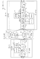
図8を用いて、本実施の形態に係る通信システム500aの構成について説明する。図8は実施の形態1で説明した図1に対応する図である。
通信システム500aは、転送装置11a,12a,・・・,1maを備える。また、N系統のレイヤ2転送網、すなわち0系レイヤ2転送網300、1系レイヤ2転送網301、・・・、(N-1)系レイヤ2転送網30(N-1)を備える。ここで、Nは3以上の整数であるとする。図8に示すように、転送装置11a,12a,・・・,1maは、0系レイヤ2転送網300、1系レイヤ2転送網301、・・・、および(N-1)系レイヤ2転送網30(N-1)に接続している。通信システム500aは、図1の通信システム500と同様、送信端末装置と受信端末装置との間に設けられ、送信端末装置から受信端末装置にパケットを転送する。
図8を用いて、本実施の形態に係る通信システム500aの構成について説明する。図8は実施の形態1で説明した図1に対応する図である。
通信システム500aは、転送装置11a,12a,・・・,1maを備える。また、N系統のレイヤ2転送網、すなわち0系レイヤ2転送網300、1系レイヤ2転送網301、・・・、(N-1)系レイヤ2転送網30(N-1)を備える。ここで、Nは3以上の整数であるとする。図8に示すように、転送装置11a,12a,・・・,1maは、0系レイヤ2転送網300、1系レイヤ2転送網301、・・・、および(N-1)系レイヤ2転送網30(N-1)に接続している。通信システム500aは、図1の通信システム500と同様、送信端末装置と受信端末装置との間に設けられ、送信端末装置から受信端末装置にパケットを転送する。
図8では、転送装置11aについては送信部10aの構成を示し、転送装置1maについては受信部20aの構成を示している。転送装置11aから1maは、パケットの送信処理を行う送信部10aと、パケットの受信処理を行う受信部20aとの両方を備える。すなわち、転送装置11aも転送装置1maと同様の受信部を備え、転送装置1maも転送装置11aと同様の送信部を備える。すなわち、転送装置12aから1(m-1)aは転送装置11aおよび転送装置1maと同様の構成を有する。転送装置11aから転送装置1maの各々は、転送装置100aの例である。
転送装置11aの送信部10aは、コピー部113をコピー部113aに替える以外は、実施の形態1の転送装置11の送信部10と同様である。コピー部113aは、送信パケットをN系統のレイヤ2転送網に送出する。
図9を用いて、本実施の形態に係る転送装置100aの受信部20aの詳細構成について説明する。
転送装置1maのタグ抽出部21aは、N系統にそれぞれ対応するタグ抽出部32-0,・・・,32-(N-1)を備える。また、遅延挿入部22aは、N系統にそれぞれ対応するバッファ32-0,・・・,32-(N-1)、読み出し決定部34-0,・・・,34-(N-1)、カウント部35-0,・・・,35-(N-1)、および読み出し制御部33aを備える。読み出し制御部33aは、タグ抽出部31-0,・・・,31-(N-1)、およびバッファ32-0,・・・,32-(N-1)を制御する。また、パケット判定部23aは、読み出し制御部33aとバッファ32-0,・・・,32-(N-1)とを制御する。
転送装置1maのタグ抽出部21aは、N系統にそれぞれ対応するタグ抽出部32-0,・・・,32-(N-1)を備える。また、遅延挿入部22aは、N系統にそれぞれ対応するバッファ32-0,・・・,32-(N-1)、読み出し決定部34-0,・・・,34-(N-1)、カウント部35-0,・・・,35-(N-1)、および読み出し制御部33aを備える。読み出し制御部33aは、タグ抽出部31-0,・・・,31-(N-1)、およびバッファ32-0,・・・,32-(N-1)を制御する。また、パケット判定部23aは、読み出し制御部33aとバッファ32-0,・・・,32-(N-1)とを制御する。
パケット判定部23aでは、実施の形態1と同様に、パケットを1パケットずつ処理する必要がある。このため、読み出し制御部33aは、以下の処理を行う。
・2系統以上のレイヤ2転送網からのパケットの選択廃棄判定要求の出力タイミングが同時となる場合、いずれか一つの選択廃棄判定要求を出力した後、選択廃棄判定が完了してから、残りの選択廃棄判定要求を出力する。
・この際、一番目に要求を出力する系、および一番目に続いて要求を出力する系の順番は、ユーザが決定できるものとする。
・いずれか一系統のレイヤ2転送網からのパケットの選択廃棄判定処理中に、残りの系の選択廃棄判定処理が発生した場合、処理中の選択廃棄判定が完了してから、残りの系の選択廃棄判定要求を出力する。
・2系統以上のレイヤ2転送網からのパケットの選択廃棄判定要求の出力タイミングが同時となる場合、いずれか一つの選択廃棄判定要求を出力した後、選択廃棄判定が完了してから、残りの選択廃棄判定要求を出力する。
・この際、一番目に要求を出力する系、および一番目に続いて要求を出力する系の順番は、ユーザが決定できるものとする。
・いずれか一系統のレイヤ2転送網からのパケットの選択廃棄判定処理中に、残りの系の選択廃棄判定処理が発生した場合、処理中の選択廃棄判定が完了してから、残りの系の選択廃棄判定要求を出力する。
***動作の説明***
転送装置1maの動作について説明する。本実施の形態では、読み出し制御部33aは、N系統のうちいずれか1系統を選択し、選択した系を非遅延系とし、残るすべての系を遅延系として読み出し制御を行う。
本実施の形態に係る転送装置1maでは、実施の形態1において2系統で実施していた動作を、N系統に拡張した動作をする。ここで、選択した非遅延系に障害が生じて、非遅延系を切替える場合、遅延系を全て非遅延系に切替えるのではなく1系統のみ非遅延系に切替える。
転送装置1maの動作について説明する。本実施の形態では、読み出し制御部33aは、N系統のうちいずれか1系統を選択し、選択した系を非遅延系とし、残るすべての系を遅延系として読み出し制御を行う。
本実施の形態に係る転送装置1maでは、実施の形態1において2系統で実施していた動作を、N系統に拡張した動作をする。ここで、選択した非遅延系に障害が生じて、非遅延系を切替える場合、遅延系を全て非遅延系に切替えるのではなく1系統のみ非遅延系に切替える。
***本実施の形態の効果の説明***
以上のように、本実施の形態に係る通信システム500aによれば、N系統のレイヤ2転送網を有する場合においても、実施の形態1と同様の効果を得ることができる。
以上のように、本実施の形態に係る通信システム500aによれば、N系統のレイヤ2転送網を有する場合においても、実施の形態1と同様の効果を得ることができる。
***他の構成***
<変形例2>
ここで、上述した実施の形態1および2に係る通信システムについて説明する。
実施の形態1および2では、バッファにパケットを格納する前にパケットから同報制御タグを抽出していた。しかし、同報制御タグの抽出を前もっては行わず、バッファからパケットを読み出し開始した後、同報制御タグの部分が読み出された時点で選択廃棄判定を実施し、判定結果が「廃棄」の場合は、当該パケットを読み飛ばす構成としてもよい。
<変形例2>
ここで、上述した実施の形態1および2に係る通信システムについて説明する。
実施の形態1および2では、バッファにパケットを格納する前にパケットから同報制御タグを抽出していた。しかし、同報制御タグの抽出を前もっては行わず、バッファからパケットを読み出し開始した後、同報制御タグの部分が読み出された時点で選択廃棄判定を実施し、判定結果が「廃棄」の場合は、当該パケットを読み飛ばす構成としてもよい。
図10は、変形例2に係る通信システム500bの構成を示す図である。
変形例2に係る通信システム500bでは、受信部20bにおいてタグ抽出部が不要となる。変形例2に係る通信システム500bでは、パケット判定部23bが、バッファ29bからパケットが読み出された際に、パケットから同報制御タグの情報を抽出し、同報制御タグに含まれるIDとシーケンス番号とに基づいてパケットを選択するか廃棄するかを判定する。
変形例2に係る送信部10bの構成および動作は、実施の形態2と同様である。
変形例2に係る通信システム500bでは、受信部20bにおいてタグ抽出部が不要となる。変形例2に係る通信システム500bでは、パケット判定部23bが、バッファ29bからパケットが読み出された際に、パケットから同報制御タグの情報を抽出し、同報制御タグに含まれるIDとシーケンス番号とに基づいてパケットを選択するか廃棄するかを判定する。
変形例2に係る送信部10bの構成および動作は、実施の形態2と同様である。
変形例2では、バッファ29bは、複数の転送網の各転送網を介して、パケットを識別するパケット識別子と、パケットの連続性を示すシーケンス番号とを含む同報制御タグが付与されたパケットを格納する。そして、読み出し開始通知Trによりパケットの読み出しが開始される。バッファ29bは、同報制御タグが読み出された時点で、パケットを選択するか廃棄するかを判定する判定要求であって同報制御タグを含む判定要求を出力する。
パケット判定部23bは、判定要求を取得し、IDとシーケンス番号とに基づいてパケットを選択するか廃棄するかを判定する。パケット判定部23bは、判定結果231をバッファおよび読み出し決定部に通知する。読み出し決定部は、パケット判定部23bによる判定結果231に基づいて、バッファ29bに格納されたパケットを最後まで読み出すか、同報制御タグ以降を読み飛ばすかを決定する。バッファ29bは、通知された判定結果231が「廃棄」であった場合、実施の形態1のステップS106と同様の処理を行う。すなわち、バッファ29bは、バッファ29bの読み出しポインタを次のパケットの先頭データが格納されている場所に飛ばすことで、1パケット分を廃棄する。
パケット判定部23bは、判定要求を取得し、IDとシーケンス番号とに基づいてパケットを選択するか廃棄するかを判定する。パケット判定部23bは、判定結果231をバッファおよび読み出し決定部に通知する。読み出し決定部は、パケット判定部23bによる判定結果231に基づいて、バッファ29bに格納されたパケットを最後まで読み出すか、同報制御タグ以降を読み飛ばすかを決定する。バッファ29bは、通知された判定結果231が「廃棄」であった場合、実施の形態1のステップS106と同様の処理を行う。すなわち、バッファ29bは、バッファ29bの読み出しポインタを次のパケットの先頭データが格納されている場所に飛ばすことで、1パケット分を廃棄する。
このように、変形例2に係る通信システム500bによれば、パケットの同報制御タグ部分までを読み出せば、当該パケットのそれ以降のデータを読み飛ばすことができる。よって、比較例と比較して、バッファからの高速な読み出し、および遅延系切替時間の短縮が可能となる。
以上の実施の形態1および2では、転送装置の各部を独立した機能ブロックとして説明した。しかし、転送装置の構成は、上述した実施の形態のような構成でなくてもよい。転送装置の機能ブロックは、上述した実施の形態で説明した機能を実現することができれば、どのような構成でもよい。
また、実施の形態1および2のうち、複数の部分を組み合わせて実施しても構わない。あるいは、これらの実施の形態のうち、1つの部分を実施しても構わない。その他、これら実施の形態を、全体としてあるいは部分的に、どのように組み合わせて実施しても構わない。
すなわち、実施の形態1および2では、各実施の形態の自由な組み合わせ、あるいは各実施の形態の任意の構成要素の変形、もしくは各実施の形態において任意の構成要素の省略が可能である。
また、実施の形態1および2のうち、複数の部分を組み合わせて実施しても構わない。あるいは、これらの実施の形態のうち、1つの部分を実施しても構わない。その他、これら実施の形態を、全体としてあるいは部分的に、どのように組み合わせて実施しても構わない。
すなわち、実施の形態1および2では、各実施の形態の自由な組み合わせ、あるいは各実施の形態の任意の構成要素の変形、もしくは各実施の形態において任意の構成要素の省略が可能である。
なお、上述した実施の形態は、本質的に好ましい例示であって、本発明の範囲、本発明の適用物の範囲、および本発明の用途の範囲を制限することを意図するものではない。上述した実施の形態は、必要に応じて種々の変更が可能である。
10,10a,10b 送信部、20,20a,20b 受信部、30,30a 転送網、11,12,12a,11a,1m,1ma 転送装置、100,100a,100b 転送装置、27,111 レイヤ2スイッチ部、112 タグ挿入部、113,113a コピー部、114 SN生成部、115 送信元保持部、21,21a,31-0,31-1,31-(N-1) タグ抽出部、22,22a,22b 遅延挿入部、23,23a,23b パケット判定部、231 判定結果、24 受信間隔タイマ部、25 SN保持部、26 タグ削除部、29,29b,32-0,32-1,32-(N-1) バッファ、34-1,34-2,34-N 読み出し決定部、33,33a 読み出し制御部、35-0,35-1,35-(N-1) カウント部、300 0系レイヤ2転送網、301 1系レイヤ2転送網、30(N-1) (N-1)系レイヤ2転送網、30N N系レイヤ2転送網、500,500a,500b 通信システム、909 電子回路、910 プロセッサ、921 メモリ、S100 転送処理、SN シーケンス番号、BSN 前シーケンス番号、Tr 読み出し開始通知。
Claims (7)
- 複数の転送網を介して複数の転送装置の各転送装置同士が同報通信する通信システムに含まれる転送装置において、
前記複数の転送網の各転送網を介して、パケットを識別するパケット識別子とパケットの連続性を示すシーケンス番号とを含む同報制御タグが付与されたパケットを取得し、前記パケットをバッファに格納するとともに前記パケットから同報制御タグの情報を抽出するタグ抽出部と、
前記タグ抽出部により抽出された前記同報制御タグの情報を取得し、前記パケット識別子と前記シーケンス番号とに基づいて前記パケットを選択するか廃棄するかを判定するパケット判定部と、
前記パケット判定部による判定結果に基づいて、前記バッファに格納された前記パケットを読み出すか読み飛ばすかを決定する読み出し決定部と
を備えた転送装置。 - 前記読み出し決定部は、
前記パケットを読み出すと決定すると、前記バッファから前記パケットを読み出し、前記パケットを読み飛ばすと決定すると、前記バッファから前記パケットを読み出さずに、前記パケットを読み飛ばす請求項1に記載の転送装置。 - 前記転送装置は、
前記バッファからパケットを読み出し始める時点を読み出し開始通知として前記読み出し決定部に出力する読み出し制御部を備え、
前記読み出し決定部は、
前記読み出し制御部から前記読み出し開始通知を受け取り、かつ、前記パケット判定部による判定結果が選択の場合に、前記パケットを読み出すと決定し、前記読み出し制御部から前記読み出し開始通知を受け取り、かつ、前記パケット判定部による判定結果が廃棄の場合に、前記パケットを読み出さないと決定する請求項1または2に記載の転送装置。 - 前記読み出し制御部は、
前記複数の転送網のいずれか1つを非遅延系の転送網とし、残りの転送網を遅延系の転送網とし、前記複数の転送網の転送網ごとに前記読み出し開始通知を出力する請求項3に記載の転送装置。 - 複数の転送網を介して複数の転送装置の各転送装置同士が同報通信する通信システムに含まれる転送装置において、
パケットを識別するパケット識別子とパケットの連続性を示すシーケンス番号とを含む同報制御タグが付与されたパケットを格納し、前記同報制御タグが読み出された時点で、前記パケットを選択するか廃棄するかを判定する判定要求であって前記同報制御タグを含む判定要求を出力するバッファと、
前記判定要求を取得し、前パケット識別子と前記シーケンス番号とに基づいて前記パケットを選択するか廃棄するかを判定するパケット判定部と、
前記パケット判定部による判定結果に基づいて、前記バッファに格納された前記パケットを読み出すか読み飛ばすかを決定する読み出し決定部と
を備えた転送装置。 - 複数の転送網を介して複数の転送装置の各転送装置同士が同報通信する通信システムに含まれる転送装置の転送方法において、
タグ抽出部が、前記複数の転送網の各転送網を介して、パケットを識別するパケット識別子とパケットの連続性を示すシーケンス番号とを含む同報制御タグが付与されたパケットを取得し、前記パケットをバッファに格納するとともに前記パケットから同報制御タグの情報を抽出し、
パケット判定部が、前記タグ抽出部により抽出された前記同報制御タグの情報を取得し、前記パケット識別子と前記シーケンス番号とに基づいて前記パケットを選択するか廃棄するかを判定し、
読み出し決定部が、前記パケット判定部による判定結果に基づいて、前記バッファに格納された前記パケットを読み出すか読み飛ばすかを決定する転送方法。 - 複数の転送網を介して複数の転送装置の各転送装置同士が同報通信する通信システムに含まれる転送装置の転送プログラムにおいて、
前記複数の転送網の各転送網を介して、パケットを識別するパケット識別子とパケットの連続性を示すシーケンス番号を含む同報制御タグが付与されたパケットを取得し、前記パケットをバッファに格納するとともに前記パケットから同報制御タグの情報を抽出するタグ抽出処理と、
前記タグ抽出処理により抽出された前記同報制御タグを取得し、前記パケット識別子と前記シーケンス番号とに基づいて前記パケットを選択するか廃棄するかを判定するパケット判定処理と、
前記パケット判定処理による判定結果に基づいて、前記バッファに格納された前記パケットを読み出すか読み飛ばすかを決定する読み出し決定処理と
をコンピュータである前記転送装置に実行させる転送プログラム。
Priority Applications (2)
| Application Number | Priority Date | Filing Date | Title |
|---|---|---|---|
| PCT/JP2018/019141 WO2019220596A1 (ja) | 2018-05-17 | 2018-05-17 | 転送装置、転送方法および転送プログラム |
| JP2019505006A JP6571901B1 (ja) | 2018-05-17 | 2018-05-17 | 転送装置、転送方法および転送プログラム |
Applications Claiming Priority (1)
| Application Number | Priority Date | Filing Date | Title |
|---|---|---|---|
| PCT/JP2018/019141 WO2019220596A1 (ja) | 2018-05-17 | 2018-05-17 | 転送装置、転送方法および転送プログラム |
Publications (1)
| Publication Number | Publication Date |
|---|---|
| WO2019220596A1 true WO2019220596A1 (ja) | 2019-11-21 |
Family
ID=67844809
Family Applications (1)
| Application Number | Title | Priority Date | Filing Date |
|---|---|---|---|
| PCT/JP2018/019141 Ceased WO2019220596A1 (ja) | 2018-05-17 | 2018-05-17 | 転送装置、転送方法および転送プログラム |
Country Status (2)
| Country | Link |
|---|---|
| JP (1) | JP6571901B1 (ja) |
| WO (1) | WO2019220596A1 (ja) |
Cited By (2)
| Publication number | Priority date | Publication date | Assignee | Title |
|---|---|---|---|---|
| JPWO2021171597A1 (ja) * | 2020-02-28 | 2021-09-02 | ||
| WO2025194910A1 (zh) * | 2024-03-18 | 2025-09-25 | 荣耀终端股份有限公司 | 一种通信方法及相关设备 |
Citations (4)
| Publication number | Priority date | Publication date | Assignee | Title |
|---|---|---|---|---|
| JP2002171494A (ja) * | 2000-12-01 | 2002-06-14 | Matsushita Electric Ind Co Ltd | 電子透かし情報埋込方法及び装置 |
| JP2008028671A (ja) * | 2006-07-20 | 2008-02-07 | Mitsubishi Electric Corp | 受信側ネットワーク装置 |
| JP2012114660A (ja) * | 2010-11-24 | 2012-06-14 | Hitachi Ltd | パケット転送装置およびパケット転送方法 |
| JP2014143592A (ja) * | 2013-01-24 | 2014-08-07 | Mitsubishi Electric Corp | スイッチ装置、通信システムおよび転送制御方法 |
-
2018
- 2018-05-17 WO PCT/JP2018/019141 patent/WO2019220596A1/ja not_active Ceased
- 2018-05-17 JP JP2019505006A patent/JP6571901B1/ja active Active
Patent Citations (4)
| Publication number | Priority date | Publication date | Assignee | Title |
|---|---|---|---|---|
| JP2002171494A (ja) * | 2000-12-01 | 2002-06-14 | Matsushita Electric Ind Co Ltd | 電子透かし情報埋込方法及び装置 |
| JP2008028671A (ja) * | 2006-07-20 | 2008-02-07 | Mitsubishi Electric Corp | 受信側ネットワーク装置 |
| JP2012114660A (ja) * | 2010-11-24 | 2012-06-14 | Hitachi Ltd | パケット転送装置およびパケット転送方法 |
| JP2014143592A (ja) * | 2013-01-24 | 2014-08-07 | Mitsubishi Electric Corp | スイッチ装置、通信システムおよび転送制御方法 |
Cited By (6)
| Publication number | Priority date | Publication date | Assignee | Title |
|---|---|---|---|---|
| JPWO2021171597A1 (ja) * | 2020-02-28 | 2021-09-02 | ||
| WO2021171597A1 (ja) * | 2020-02-28 | 2021-09-02 | 日本電信電話株式会社 | 通信システム、通信方法、送信側切替装置、受信側切替装置、及びプログラム |
| JP7351403B2 (ja) | 2020-02-28 | 2023-09-27 | 日本電信電話株式会社 | 通信システム、通信方法、送信側切替装置、受信側切替装置、及びプログラム |
| US20230336501A1 (en) * | 2020-02-28 | 2023-10-19 | Nippon Telegraph And Telephone Corporation | Communication system, communication method, transmitting side switching device, receiving side switching device, and program |
| US12088511B2 (en) | 2020-02-28 | 2024-09-10 | Nippon Telegraph And Telephone Corporation | Communication system, communication method, transmitting side switching device, receiving side switching device, and program |
| WO2025194910A1 (zh) * | 2024-03-18 | 2025-09-25 | 荣耀终端股份有限公司 | 一种通信方法及相关设备 |
Also Published As
| Publication number | Publication date |
|---|---|
| JPWO2019220596A1 (ja) | 2020-05-28 |
| JP6571901B1 (ja) | 2019-09-04 |
Similar Documents
| Publication | Publication Date | Title |
|---|---|---|
| US8625588B2 (en) | Packet transmission method and packet transmission device | |
| JP4074304B2 (ja) | パケット転送方法及びパケット転送装置 | |
| JP5668938B2 (ja) | パケット整列装置、受信装置、及びパケット整列方法 | |
| JP2007209040A (ja) | パケット転送方法及びパケット転送装置 | |
| CN114125081B (zh) | 一种接收数据的处理方法、装置及存储介质 | |
| JP6571901B1 (ja) | 転送装置、転送方法および転送プログラム | |
| US8611207B2 (en) | Data transmitter and data transmission method | |
| JP6800375B2 (ja) | 通信装置、通信方法及び通信プログラム | |
| JP4068545B2 (ja) | パケット受信方法および装置 | |
| JP5519387B2 (ja) | 伝送装置、伝送プログラム及び伝送方法 | |
| US9641461B2 (en) | Relay device, communication system, and communication method | |
| US11616661B2 (en) | Transfer device and transfer method | |
| JP4271787B2 (ja) | 通信システム | |
| JP6494880B2 (ja) | 転送装置およびフレーム転送方法 | |
| WO2004066562A1 (ja) | データ転送装置 | |
| US9391791B2 (en) | Preprocessing unit for network data | |
| TW202535047A (zh) | 封包傳送裝置及封包傳送方法 | |
| JP6099412B2 (ja) | スイッチ装置、通信システムおよび転送制御方法 | |
| US20160112318A1 (en) | Information processing system, method, and information processing apparatus | |
| KR20170046901A (ko) | 데이터 중복 제거의 딕셔너리 동기화 방법 | |
| JP2015231210A (ja) | パケット転送装置およびパケット転送方法 | |
| JP7034397B2 (ja) | 経路冗長化システム、送信側装置、受信側装置、経路冗長化方法、および、経路冗長化プログラム | |
| JP6217206B2 (ja) | 通信制御装置、画像処理装置、転送制御プログラム | |
| JP2018092305A (ja) | 中継装置 |
Legal Events
| Date | Code | Title | Description |
|---|---|---|---|
| ENP | Entry into the national phase |
Ref document number: 2019505006 Country of ref document: JP Kind code of ref document: A |
|
| 121 | Ep: the epo has been informed by wipo that ep was designated in this application |
Ref document number: 18919176 Country of ref document: EP Kind code of ref document: A1 |
|
| NENP | Non-entry into the national phase |
Ref country code: DE |
|
| 122 | Ep: pct application non-entry in european phase |
Ref document number: 18919176 Country of ref document: EP Kind code of ref document: A1 |