WO2019216337A1 - エンジン制御装置及びエンジン - Google Patents
エンジン制御装置及びエンジン Download PDFInfo
- Publication number
- WO2019216337A1 WO2019216337A1 PCT/JP2019/018372 JP2019018372W WO2019216337A1 WO 2019216337 A1 WO2019216337 A1 WO 2019216337A1 JP 2019018372 W JP2019018372 W JP 2019018372W WO 2019216337 A1 WO2019216337 A1 WO 2019216337A1
- Authority
- WO
- WIPO (PCT)
- Prior art keywords
- engine
- plunger
- rack
- abnormality
- control device
- Prior art date
- Legal status (The legal status is an assumption and is not a legal conclusion. Google has not performed a legal analysis and makes no representation as to the accuracy of the status listed.)
- Ceased
Links
Images



Classifications
-
- F—MECHANICAL ENGINEERING; LIGHTING; HEATING; WEAPONS; BLASTING
- F02—COMBUSTION ENGINES; HOT-GAS OR COMBUSTION-PRODUCT ENGINE PLANTS
- F02D—CONTROLLING COMBUSTION ENGINES
- F02D1/00—Controlling fuel-injection pumps, e.g. of high pressure injection type
- F02D1/02—Controlling fuel-injection pumps, e.g. of high pressure injection type not restricted to adjustment of injection timing, e.g. varying amount of fuel delivered
Definitions
- the present invention mainly relates to an engine control device that performs control to determine and eliminate an abnormality in the operation of a rack provided in a fuel pump.
- the fuel pump provided in the engine includes a plunger and a rack.
- the plunger is disposed within the plunger barrel.
- the plunger is configured to reciprocate in accordance with the operation of the engine, and fuel is supplied to the combustion chamber by reciprocating the plunger.
- the plunger is configured to be rotatable in the axial direction, and an amount of fuel corresponding to the rotational position is supplied to the combustion chamber.
- the rack is connected to the plunger, and the plunger can be rotated by linearly moving the rack.
- Patent documents 1 and 2 disclose an engine capable of removing a fuel film or the like generated on the outer periphery of the plunger.
- the engine disclosed in Patent Document 1 includes two actuators having different maximum outputs.
- the rack and the plunger are operated using an actuator having a large maximum output.
- the actuator having the smaller maximum output is generated on the outer periphery of the plunger, the fuel film or the like can be removed.
- Patent Document 2 discloses a method of removing a fuel film or the like generated on the outer periphery of a plunger by operating a plunger and a rack by driving a starter motor. Further, when the starter motor is driven, there is a possibility that the engine is started before the fuel film or the like formed on the outer periphery of the plunger is removed. Therefore, in Patent Document 2, when the starter motor is driven, the shutoff valve that shuts off the fuel supply to the combustion chamber is closed.
- JP-A-2015-178882 Japanese Patent Laying-Open No. 2015-68293
- the present invention has been made in view of the above circumstances, and a main object of the present invention is to provide an engine control device capable of controlling the removal of a fuel film or the like generated on the outer periphery of a plunger with a simple configuration. .
- an engine control device having the following configuration. That is, the engine control device performs control to operate the fuel pump rack and rotate the plunger.
- the engine control device includes an abnormality determination unit and an abnormality elimination unit.
- the abnormality determination unit operates the rack to determine whether there is an abnormality in the operation of the rack.
- the abnormality resolving unit reciprocates the plunger together with the crankshaft without starting the engine by intermittently energizing the starter motor when the abnormality determining unit determines that the rack operation is abnormal. Perform the canceling action.
- the canceling operation can be performed without starting the engine.
- the configuration only for removing the fuel film or the like generated on the outer periphery of the plunger is unnecessary, the abnormal operation of the rack can be eliminated with a simple configuration.
- the engine control apparatus has the following configuration. That is, the engine control device includes a voltage acquisition unit that acquires a voltage value of a battery that applies a voltage to the starter motor.
- the abnormality elimination unit lengthens the energization time per time when the starter motor is intermittently energized as the voltage value acquired by the voltage acquisition unit is lower.
- the engine control apparatus has the following configuration. That is, the engine control device includes a time acquisition unit that acquires the cumulative operation time of the engine.
- the abnormality elimination unit increases the energization time per one time when the starter motor is intermittently energized as the cumulative operation time acquired by the time acquisition unit is longer.
- an engine having the following configuration includes a fuel pump, a starter motor, and an engine control device.
- the fuel pump includes a rack and a plunger, and the plunger rotates when the rack operates.
- the starter motor rotates the crankshaft and reciprocates the plunger when voltage is applied.
- the engine control device intermittently energizes the starter motor, thereby eliminating the operation of reciprocating the plunger together with the crankshaft without starting the engine. I do.
- the canceling operation can be performed without starting the engine.
- the flowchart which shows the process regarding abnormality determination of rack operation
- the graph which shows the time change of the voltage at the time of supplying with electricity to a starter motor in order to reciprocate a plunger.
- the figure which shows the map for calculating a correction coefficient.
- FIG. 1 is a diagram showing a configuration of an engine 1 according to an embodiment of the present invention.
- the engine 1 of the present embodiment is an internal combustion engine, and is disposed in, for example, a ship, a work vehicle, and a generator.
- the engine 1 of this embodiment is a diesel engine, it may be an engine having a different configuration (for example, an engine that can use both diesel fuel and gas fuel).
- the engine 1 includes a power generation unit 10 that generates power using fuel.
- the power generation unit 10 includes a cylinder block 11, and a cylinder 12 is formed inside the cylinder block 11.
- a plurality of cylinders 12 are formed in the cylinder block 11, but a configuration in which one cylinder 12 is formed may be employed.
- a piston 13 is disposed in the cylinder 12. The piston 13 is configured to reciprocate in the axial direction along the inner wall of the cylinder 12.
- a space defined by the inner wall of the cylinder 12 and one side of the piston 13 (a surface opposite to the crankshaft 18 and the upper surface) functions as a combustion chamber.
- the cylinder 12 combustion chamber
- the cylinder 12 is provided with an intake valve 14, a fuel injection nozzle 15, and an exhaust valve 16.
- the intake valve 14 can switch between opening and closing an intake port formed in the combustion chamber, and supplies air to the combustion chamber at an appropriate timing.
- the fuel injection nozzle 15 injects high-pressure fuel into the combustion chamber when the piston 13 is at or near top dead center (when air is compressed). As a result, the fuel spontaneously ignites and burns, and the piston is pushed downward.
- the exhaust valve 16 can switch between opening and closing an exhaust port formed in the combustion chamber, and exhausts the exhaust gas after combustion from the combustion chamber at an appropriate timing.
- a connecting rod 17 is rotatably attached to the piston 13.
- the connecting rod 17 converts the linear motion of the piston 13 into a rotational motion and transmits it to the crankshaft 18.
- the power generated by the power generation unit 10 is output from the crankshaft 18 that is the output shaft.
- the power output from the crankshaft 18 is used, for example, for moving a moving body, or for generating power from a generator.
- the fuel pump 20 includes a plurality of fuel supply units 21.
- the fuel supply unit 21 supplies the fuel stored in a fuel tank (not shown) to the power generation unit 10 (fuel injection nozzle 15).
- the fuel pump 20 includes the same number of fuel supply units 21 as the cylinders 12 so that fuel can be supplied to each cylinder 12 of the power generation unit 10.
- the fuel pump 20 may include a single fuel supply unit 21.
- the fuel pump 20 of the present embodiment is an in-line type disposed outside the fuel tank, but may be an in-tank type disposed inside the fuel tank.
- the fuel supply unit 21 includes a plunger barrel 31 and a plunger 32.
- the plunger barrel 31 is a cylindrical member and has an internal space.
- the plunger barrel 31 has a fuel port (not shown) for supplying fuel from the fuel tank to the internal space.
- the plunger 32 is a cylindrical member and is disposed in the internal space of the plunger barrel 31.
- the plunger 32 is configured to reciprocate up and down (in the axial direction) along the inner wall of the plunger barrel 31.
- the camshaft 22 is disposed below the plunger 32.
- a plurality of cams 23 (the same number as the fuel supply unit 21) are fixed to the camshaft 22.
- the plunger 32 is biased so as to be pressed against the cam 23 by a spring 33. With this configuration, the plunger 32 can be reciprocated up and down according to the cam diameter of the cam 23.
- the camshaft 22 is connected to the crankshaft 18 via a power transmission mechanism (not shown). With this configuration, the camshaft 22 rotates as the crankshaft 18 rotates, and the plunger 32 reciprocates up and down.
- the plunger 32 of this embodiment is arrange
- a fuel valve 34 that is opened when a pressure equal to or higher than a threshold is applied is disposed above the plunger 32. With this configuration, when the plunger barrel 31 rises and the pressure in the internal space exceeds the threshold value, the fuel valve 34 is opened and the fuel passes through the fuel valve 34. The fuel that has passed through the fuel valve 34 is injected from the fuel injection nozzle 15 into the combustion chamber via the fuel supply pipe.
- the plunger 32 is configured to be rotatable about the vertical direction (axial direction) as the rotation center.
- the fuel supply unit 21 includes a gear (pinion gear) 35 that rotates integrally with the plunger 32.
- the fuel pump 20 includes a rack 24 that is arranged to mesh with the gear 35.
- the rack 24 is disposed so as to mesh with all of the gears 35 provided in each of the plurality of fuel supply units 21.
- the actuator 25 is, for example, a solenoid, but may have other configurations (for example, a device that combines a ball screw and a motor).
- the position sensor 26 is a sensing rod that performs linear motion with the rack 24, for example.
- the plunger 32 is configured to change the amount of fuel supplied to the fuel injection nozzle 15 by a known structure by rotating about the axial direction as a rotation center. That is, the fuel port is formed in the plunger barrel 31 as described above. Until the plunger 32 closes the fuel port, even if the plunger 32 moves up, the fuel in the internal space escapes to the fuel tank side through the fuel port. Since the plunger 32 ascends and closes the fuel port, the fuel in the internal space does not escape to the fuel tank side, so the amount of fuel supplied to the fuel injection nozzle 15 based on the amount of fuel present in the internal space at that time Is determined.
- a plunger lead 32 a which is a spiral groove is formed on the surface of the plunger 32. Accordingly, by rotating the plunger 32, the timing at which the plunger lead 32a closes the fuel port of the plunger barrel 31 changes, so that the amount of fuel supplied to the fuel injection nozzle 15 can be changed.
- the engine 1 includes a starter motor 41, a key switch 42, a battery 43, a battery sensor 44, and an engine control device 50.
- the starter motor 41 is a motor for starting the engine 1. Specifically, the starter motor 41 starts the engine 1 by rotating the crankshaft 18 and the camshaft 22 when a voltage is applied from the battery 43. It should be noted that starting the engine 1 is a state in which intake, compression, combustion, and exhaust strokes are continuously performed even when the starter motor 41 is stopped.
- the key switch 42 is a switch for starting the engine 1. By turning on the key switch 42, the engine 1 is started by applying a voltage to the starter motor 41 (by supplying power) after an abnormality test described later.
- the battery 43 is charged by an unillustrated alternator and supplies power to the electrical equipment that constitutes the engine 1.
- the battery sensor 44 measures the voltage value of the battery 43.
- the engine control device 50 is configured as a known computer and includes a CPU, a ROM, a RAM, an input / output unit, and the like (not shown). Various programs and data for controlling the engine are stored in the ROM. The CPU can read various programs from the ROM and execute them. The engine control device 50 can be operated as the voltage acquisition unit 51, the time acquisition unit 52, the abnormality determination unit 53, and the abnormality elimination unit 54 through the cooperation of the hardware and software. The processing performed by each unit of the engine control device 50 will be described later.
- the engine control device 50 is configured to operate the actuator 25, the starter motor 41, and the like.
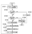
- FIG. 2 is a flowchart showing processing related to abnormality determination and abnormality elimination of the operation of the rack 24.
- FIG. 3 is a graph showing a change in voltage over time when the starter motor 41 is energized to reciprocate the plunger 32.
- FIG. 4 is a diagram showing a map for calculating the correction coefficient.
- a fuel film or the like may occur on the outer periphery of the plunger 32.
- This fuel film or the like serves as a rotational resistance when the plunger 32 is rotated.
- the amount of fuel supplied to the fuel injection nozzle 15 that is, the fuel injection amount
- the engine 1 determines whether or not the plunger 32 can appropriately rotate, and performs a process of permitting the start of the engine 1 only when the plunger 32 can appropriately rotate.
- the abnormality determination unit 53 of the engine control device 50 determines whether or not the operation of the rack 24 is abnormal. Specifically, the abnormality determination unit 53 controls the actuator 25 to perform an inspection operation using the rack 24 (S101). The rotation of the plunger 32 and the operation (linear motion) of the rack 24 are linked, and the engine control device 50 rotates the plunger 32 via the rack 24. Therefore, in this embodiment, the plunger 32 is operated by operating the rack 24. It is determined whether or not can rotate properly. Further, the inspection operation of the present embodiment is an operation of moving the rack 24 from one end to the other end, but other operations may be performed as the inspection operation.
- the abnormality determination unit 53 determines whether or not there is an abnormality in the operation of the rack 24 based on the result of the inspection operation in the rack 24 (S102). For example, the abnormality determination unit 53 determines that there is an abnormality in the operation of the rack 24 when the time taken for the rack 24 to complete the inspection operation is equal to or greater than a threshold value. The abnormality determination unit 53 can also determine that there is an abnormality in the operation of the rack 24 when the rack 24 cannot reach one end or the other end. Whether or not the rack 24 has reached one end or the other end can be specified based on the detection result of the position sensor 26.
- the engine control device 50 permits the engine 1 to start when there is no abnormality in the operation of the rack 24 and the operation of the rack 24 is normal. Then, the engine control device 50 performs an engine start process (S103).
- the engine start process is a process for starting the engine 1 by continuously energizing the starter motor 41 for a predetermined time or more.
- the engine control device 50 determines whether or not the number of inspections of the rack 24 is equal to or greater than a threshold value (N times) (S104). By causing the rack 24 to perform an inspection operation (S101) and determining whether or not the operation of the rack 24 is abnormal (S102), it is determined that one inspection has been performed.
- the engine control device 50 determines that the number of inspections is less than N times, the engine control device 50 causes the plunger 32 to perform a canceling operation that is an operation for canceling the abnormal operation of the rack 24.
- the starter motor 41 is energized, the crankshaft 18 is rotated and the plunger 32 is reciprocated.
- the plunger 32 reciprocates in the plunger barrel 31, there is a possibility that the fuel film or the like attached to the outer periphery of the plunger 32 is removed.
- the energization time of the starter motor 41 is increased, the engine 1 is started. Since it is not preferable that the engine 1 is started during the inspection of the operation of the rack 24, a process for reciprocating the plunger 32 while preventing the engine 1 from starting is necessary.
- the starter motor 41 is energized intermittently (voltage is applied).
- the intermittent energization means that the battery 43 is energized to the starter motor 41 (energized state) and the battery 43 is not energized to the starter motor 41 (non-energized state) in a short time. is there.
- the time length of a non-energized state is shorter than the time until the crankshaft 18 and the camshaft 22 which are rotating with the starter motor 41 being energized, for example. If it demonstrates from another viewpoint, it is preferable that the rotation speed of the crankshaft 18 becomes a grade which the engine 1 does not start by repeating an energized state and a non-energized state.
- the number of energizations performed in one canceling operation is not limited, and is, for example, 10 times or less or 5 times or less.
- the starter relay is used to switch between the energized state and the non-energized state, so that the voltage applied to the starter motor 41 is substantially zero in the non-energized state.
- a configuration in which a slight voltage is applied to the starter motor 41 even in a non-energized state may be employed.
- the voltage acquisition unit 51 of the engine control device 50 acquires the voltage value of the battery 43 from the battery sensor 44 (S105).
- the time acquisition unit 52 of the engine control device 50 acquires the cumulative operation time of the engine 1 (S106).
- the cumulative operation time is a total value of the time that the engine 1 has been operating up to the present time. That is, even if the engine 1 is restarted after being stopped, the time after restart is added to the cumulative operation time before stopping.
- the time acquisition unit 52 is configured to acquire the cumulative operation time of the engine 1 based on data stored in the engine control device 50, but the cumulative operation of the engine 1 from a device external to the engine control device 50. You may get time.
- the abnormality elimination unit 54 of the engine control device 50 calculates a correction coefficient for one energization time.
- the energization time is a time length of one energization state among energizations performed a plurality of times.
- the correction coefficient is a coefficient for determining the time length of one energized state, and the correction coefficient increases as the engine 1 is more difficult to start.
- a standard energization time is determined in advance in consideration of the specifications of the engine 1 and the like.
- the abnormality eliminating unit 54 performs a canceling operation of energizing the starter motor 41 with a value obtained by multiplying the standard energizing time by the correction coefficient as one energizing time (S108). Note that switching of whether the starter motor 41 is energized can be realized by, for example, a pulse width modulation technique.
- the engine 1 becomes difficult to start as the voltage value of the battery 43 decreases. Therefore, as shown in FIG. 4, as the voltage value of the battery 43 decreases, the correction coefficient is increased (that is, the energization time is increased). Further, the longer the cumulative operation time, the more difficult the engine 1 starts due to deterioration of the fuel pump 20 and each part. Therefore, as shown in FIG. 4, the correction coefficient is increased as the cumulative operation time becomes longer (that is, the energization time is lengthened). Accordingly, the fuel film and the like can be removed by reciprocating the plunger 32 while preventing both the situation where the piston 13 cannot exceed the compression stroke and the start of the engine 1.
- the voltage value of the battery 43 and the cumulative operation time are used as data for calculating the correction coefficient.
- other data related to difficulty in starting the engine 1 are used.
- the correction coefficient may be calculated based on data (for example, outside air temperature or atmospheric pressure).
- the abnormality determining unit 53 After the canceling operation by the abnormality eliminating unit 54, the abnormality determining unit 53 performs the processes of steps S101 and S102 again.
- the engine start process in step S103 is performed. If the rack operation is still abnormal after the canceling operation, the processing from step S104 to S108 is performed again. Thus, the canceling operation is performed until the rack operation becomes normal. If the number of inspections is N or more, the process is stopped and a warning is given to the effect that the rack operation is abnormal (S109).
- the engine 1 of the present embodiment includes a plurality of plungers 32, a fuel film or the like may be generated in each plunger 32. Therefore, if a fuel film or the like is generated on all the plungers 32, the abnormal operation of the rack 24 cannot be resolved unless all the plungers 32 are operated. However, since each plunger 32 reciprocates at different timings, in order to reciprocate all the plungers 32, it is necessary to change the rotation angle of the crankshaft 18 greatly. However, when the crankshaft 18 is rotated in this way, the engine 1 is likely to start. In consideration of the above, in this embodiment, in one canceling operation, the crankshaft 18 is rotated by an angle smaller than the angle at which all the plungers 32 reciprocate.
- the crankshaft 18 is rotated by an angle at which only one plunger 32 reciprocates. Then, if the abnormality of the rack 24 is not resolved, the crankshaft 18 is rotated again so that the fuel film can be removed regardless of which plunger 32 has a fuel film or the like.
- the rotation angle of the crankshaft 18 in one canceling operation the fuel film generated on the outer periphery of the plunger 32 can be removed while preventing the engine 1 from starting.
- the fuel pump 20 of the present embodiment is an in-line type, the fuel injection amount is likely to increase even at a low speed. Therefore, the engine 1 is easy to start. However, by performing the processing of this embodiment, the crankshaft 18 can be rotated while preventing the engine 1 from starting, and the fuel film generated on the outer periphery of the plunger 32 can be removed.
- the engine control device 50 controls the plunger 32 to rotate by operating the rack 24 of the fuel pump 20.
- the engine control device 50 includes an abnormality determination unit 53 and an abnormality elimination unit 54.
- the abnormality determination unit 53 operates the rack 24 to determine whether there is an abnormality in the operation of the rack 24.
- the abnormality eliminating unit 54 intermittently energizes the starter motor 41 when the abnormality determining unit 53 determines that the operation of the rack 24 is abnormal, whereby the plunger 32 together with the crankshaft 18 is not started. The resolving action to reciprocate is performed.
- the canceling operation can be performed without starting the engine 1.
- the configuration only for removing the fuel film or the like generated on the outer periphery of the plunger 32 is not necessary, the abnormal operation of the rack 24 can be eliminated with a simple configuration.
- the engine control device 50 of the present embodiment includes a voltage acquisition unit 51 that acquires a voltage value of the battery 43 that applies a voltage to the starter motor 41. As the voltage value acquired by the voltage acquisition unit 51 is lower, the abnormality elimination unit 54 lengthens the energization time per time when the starter motor 41 is intermittently energized.
- the engine 1 When the voltage of the battery 43 is low, the engine 1 is difficult to start even if the energization time per time is extended. Thereby, the plunger 32 can be reciprocated more reliably in the elimination operation.
- the engine control device 50 of the present embodiment includes a time acquisition unit 52 that acquires the cumulative operation time of the engine 1.
- the engine 1 When the cumulative operation time of the engine 1 is long, the engine 1 is difficult to start even if the energization time per time is extended due to deterioration of parts such as the fuel pump 20. Thereby, the plunger 32 can be reciprocated more reliably in the elimination operation.
- the engine 1 of the present embodiment includes a fuel pump 20, a starter motor 41, and an engine control device 50.
- the fuel pump 20 includes a rack 24 and a plunger 32, and the plunger 32 rotates as the rack 24 operates.
- the starter motor 41 rotates the crankshaft 18 and reciprocates the plunger 32 by applying a voltage.
- the starter motor 41 is energized intermittently to cancel the reciprocating motion of the plunger 32 together with the crankshaft 18 without starting the engine 1. Perform the action.
- the canceling operation can be performed without starting the engine 1.
- the flowchart shown in FIG. 2 is an example, and processing can be added, changed, or omitted.
- the second resolution operation is performed. May be notified.
- the energization time per time is increased.
- the number of times of energization may be increased. That is, when the engine 1 is difficult to start, the cumulative energization time in one canceling operation may be increased.
Landscapes
- Engineering & Computer Science (AREA)
- Chemical & Material Sciences (AREA)
- Combustion & Propulsion (AREA)
- Mechanical Engineering (AREA)
- General Engineering & Computer Science (AREA)
- Electrical Control Of Air Or Fuel Supplied To Internal-Combustion Engine (AREA)
- High-Pressure Fuel Injection Pump Control (AREA)
Abstract
エンジン制御装置は、燃料ポンプのラックを動作させてプランジャを回転させる制御を行う。このエンジン制御装置は、異常判定部と、異常解消部と、を備える。異常判定部は、ラックを動作させて当該ラックの動作の異常の有無を判定する。異常解消部は、ラックの動作に異常があると異常判定部が判定した場合に、スタータモータに間欠的に通電することで、エンジンを始動させずにクランク軸とともにプランジャを往復動させる解消動作を行う。
Description
本発明は、主として、燃料ポンプが備えるラックの動作の異常を判定して解消する制御を行うエンジン制御装置に関する。
エンジンが備える燃料ポンプは、プランジャと、ラックと、を備える。プランジャは、プランジャバレル内に配置されている。プランジャは、エンジンの動作に合わせて往復動するように構成されており、プランジャを往復動させることで燃焼室へ燃料が供給される。また、プランジャは、軸方向に回転可能に構成されており、回転位置に応じた量の燃料が燃焼室へ供給される。ラックはプランジャに連結されており、このラックを直線移動させることでプランジャを回転させることができる。
ここで、プランジャの外周に燃料膜等が生じることにより、プランジャが適切に回転しにくくなることがある。また、プランジャの回転とラックの直線移動は連動しているため、プランジャだけでなくラックも適切に動作しにくくなる。特許文献1及び2は、プランジャの外周に生じた燃料膜等を除去することができるエンジンを開示する。
特許文献1のエンジンは、最大出力が異なる2つのアクチュエータを備える。このエンジンでは、ラックの動作に異常があると判定した場合、最大出力が大きいアクチュエータを用いてラック及びプランジャを動作させる。これにより、最大出力が小さい方のアクチュエータでは除去できない燃料膜等がプランジャの外周に生じていた場合であってもこの燃料膜等を除去できる。
特許文献2は、スタータモータを駆動してプランジャ及びラックを動作させることで、プランジャの外周に生じた燃料膜等を除去する方法を開示する。また、スタータモータを駆動する場合、プランジャの外周に生じた燃料膜等の除去前にエンジンが始動する可能性がある。そのため、特許文献2ではスタータモータを駆動する際に燃焼室内への燃料の供給を遮断する遮断弁を閉状態にする。
しかし、特許文献1の方法では、プランジャの外周に生じた燃料膜等を除去するためにアクチュエータが更に必要となる。また、特許文献2の方法では、遮断弁及びこの遮断弁を動作させる構成が必要となる。従って、特許文献1及び2等とは異なる方法で、プランジャの外周に生じた燃料膜等を除去する方法が望まれていた。
本発明は以上の事情に鑑みてされたものであり、その主要な目的は、単純な構成でプランジャの外周に生じた燃料膜等を除去する制御が可能なエンジン制御装置を提供することにある。
本発明の解決しようとする課題は以上の如くであり、次にこの課題を解決するための手段とその効果を説明する。
本発明の第1の観点によれば、以下の構成のエンジン制御装置が提供される。即ち、このエンジン制御装置は、燃料ポンプのラックを動作させてプランジャを回転させる制御を行う。このエンジン制御装置は、異常判定部と、異常解消部と、を備える。前記異常判定部は、前記ラックを動作させて当該ラックの動作の異常の有無を判定する。前記異常解消部は、前記ラックの動作に異常があると前記異常判定部が判定した場合に、スタータモータに間欠的に通電することで、エンジンを始動させずにクランク軸とともに前記プランジャを往復動させる解消動作を行う。
これにより、スタータモータに間欠的に通電することで、エンジンを始動させることなく、解消動作を行うことができる。また、プランジャの外周に生じた燃料膜等を除去するためだけの構成が不要であるため、ラックの動作の異常を単純な構成で解消できる。
前記のエンジン制御装置においては、以下の構成とすることが好ましい。即ち、このエンジン制御装置は、前記スタータモータに電圧を印加するバッテリーの電圧値を取得する電圧取得部を備える。前記異常解消部は、前記電圧取得部が取得した前記電圧値が低いほど、前記スタータモータに間欠的に通電する際の1回あたりの通電時間を長くする。
バッテリーの電圧が低い場合は、1回あたりの通電時間を長くしてもエンジンが始動しにくい。これにより、解消動作において一層確実にプランジャを往復動させることができる。
前記のエンジン制御装置においては、以下の構成とすることが好ましい。即ち、このエンジン制御装置は、前記エンジンの累計運転時間を取得する時間取得部を備える。前記異常解消部は、前記時間取得部が取得した前記累計運転時間が長いほど、前記スタータモータに間欠的に通電する際の1回あたりの通電時間を長くする。
エンジンの累計運転時間が長い場合は、燃料ポンプ等の部品の劣化により、1回あたりの通電時間を長くしてもエンジンが始動しにくい。これにより、解消動作において一層確実にプランジャを往復動させることができる。
本発明の第2の観点によれば、以下の構成のエンジンが提供される。即ち、このエンジンは、燃料ポンプと、スタータモータと、エンジン制御装置と、を備える。前記燃料ポンプは、ラック及びプランジャを備え、当該ラックが動作することでプランジャが回転する構成である。前記スタータモータは、電圧が印加されることでクランク軸を回転させるとともにプランジャを往復動させる。前記エンジン制御装置は、前記ラックの動作に異常があると判定した場合に、前記スタータモータに間欠的に通電することで、エンジンを始動させずに前記クランク軸とともに前記プランジャを往復動させる解消動作を行う。
これにより、スタータモータに間欠的に通電することで、エンジンを始動させることなく、解消動作を行うことができる。
次に、図面を参照して本発明の実施形態を説明する。初めに図1を参照して、本実施形態のエンジン1について説明する。図1は、本発明の一実施形態に係るエンジン1の構成を示す図である。
本実施形態のエンジン1は内燃機関であり、例えば、船舶、作業車両、及び発電機等に配置される。本実施形態のエンジン1はディーゼルエンジンであるが、異なる構成のエンジン(例えばディーゼル燃料とガス燃料の両方を使用可能なエンジン)であってもよい。図1に示すように、エンジン1は、燃料を用いて動力を発生させる動力発生部10を備える。
動力発生部10は、シリンダブロック11を備えており、シリンダブロック11の内部には、シリンダ12が形成されている。本実施形態では、シリンダブロック11には複数のシリンダ12が形成されているが、1つのシリンダ12が形成されている構成であってもよい。シリンダ12にはピストン13が配置されている。ピストン13はシリンダ12の内壁に沿って軸方向に往復動できるように構成されている。
また、シリンダ12の内壁と、ピストン13の一側の面(クランク軸18と反対側の面、上面)と、で区画される空間は燃焼室として機能する。また、シリンダ12(燃焼室)には、吸気バルブ14、燃料噴射ノズル15、及び排気バルブ16が設けられている。
吸気バルブ14は、燃焼室に形成された吸気ポートの開放及び閉鎖を切替可能であり、適当なタイミングで燃焼室に空気を供給する。燃料噴射ノズル15は、ピストン13が上死点又はその付近にあるときに(空気が圧縮されたときに)、高圧の燃料を燃焼室へ噴射する。これにより、燃料が自然着火して燃焼し、ピストンが下方へ押し下げられる。排気バルブ16は、燃焼室に形成された排気ポートの開放及び閉鎖を切替可能であり、適当なタイミングで燃焼後の排気ガスを燃焼室から排出する。
ピストン13にはコネクティングロッド17が回転可能に取り付けられている。コネクティングロッド17は、ピストン13の直線運動を回転運動に変換してクランク軸18へ伝達する。以上により、動力発生部10で発生した動力は、出力軸であるクランク軸18から出力される。クランク軸18から出力された動力は、例えば移動体の移動のために用いられたり、発電機の発電のため等に用いられたりする。
次に、動力発生部10に燃料を供給する燃料ポンプ20について説明する。
図1に示すように、燃料ポンプ20は、複数の燃料供給部21を備える。燃料供給部21は、図略の燃料タンクに貯留されている燃料を動力発生部10(燃料噴射ノズル15)へ供給する。燃料ポンプ20は、動力発生部10のシリンダ12毎に燃料を供給できるように、シリンダ12と同数の燃料供給部21を備えている。なお、燃料ポンプ20が1つの燃料供給部21を備える構成であってもよい。また、本実施形態の燃料ポンプ20は、燃料タンクの外部に配置されているインライン型であるが、燃料タンクの内部に配置されるインタンク型であってもよい。
燃料供給部21は、プランジャバレル31及びプランジャ32を備える。プランジャバレル31は円筒状の部材であり、内部空間が形成されている。また、プランジャバレル31には、燃料タンクから内部空間に燃料を供給するための図略の燃料ポートが形成されている。プランジャ32は円柱状の部材であり、プランジャバレル31の内部空間に配置されている。プランジャ32は、プランジャバレル31の内壁に沿って上下に(軸方向に)往復動できるように構成されている。
具体的には、プランジャ32の下方にはカムシャフト22が配置されている。カムシャフト22には複数の(燃料供給部21と同数の)カム23が固定されている。プランジャ32は、スプリング33によってカム23側に押し付けられるように付勢されている。この構成により、カム23のカム径に応じてプランジャ32を上下に往復動させることができる。
また、カムシャフト22は、図略の動力伝達機構を介してクランク軸18と連結されている。この構成により、クランク軸18の回転に伴ってカムシャフト22が回転するとともに、プランジャ32が上下に往復動する。なお、本実施形態のプランジャ32は、軸方向と上下方向(鉛直方向)とが同じ方向となるように配置されているが、異なる方向となるように配置されていてもよい。
上述のようにプランジャバレル31の内部空間には燃料が供給されているため、プランジャ32が上方向に移動することで内部空間の圧力が上昇する。また、プランジャ32の上側には、閾値以上の圧力が掛かった場合に開放する燃料バルブ34が配置されている。この構成により、プランジャバレル31が上昇して内部空間の圧力が閾値を超えることで、燃料バルブ34が開放して燃料が当該燃料バルブ34を通過する。燃料バルブ34を通過した燃料は、燃料供給管を介して燃料噴射ノズル15から燃焼室へ噴射される。
また、プランジャ32は、上下方向(軸方向)を回転中心として回転可能に構成されている。具体的には、燃料供給部21は、プランジャ32と一体的に回転するギア(ピニオンギア)35を備える。また、燃料ポンプ20は、ギア35に噛み合うように配置されたラック24を備える。ラック24は、複数の燃料供給部21がそれぞれ備えるギア35の全てと噛み合うように配置されている。この構成により、燃料ポンプ20が備えるアクチュエータ25によりラック24を直線運動させることで、複数のプランジャ32を同時に回転させることができる。アクチュエータ25は例えばソレノイドであるが、他の構成(例えばボールネジとモータを組み合せた装置)であってもよい。
また、ラック24の位置は、位置センサ26によって検出される。位置センサ26は、例えばラック24とともに直線運動を行うセンシングロッドである。
プランジャ32は軸方向を回転中心として回転することで、公知の構造により、燃料噴射ノズル15への燃料供給量を変化させることができるように構成されている。即ち、上述したようにプランジャバレル31には燃料ポートが形成されている。プランジャ32が燃料ポートを塞ぐまでの間は、プランジャ32が上昇しても、内部空間内の燃料が燃料ポートを介して燃料タンク側へ逃げる。プランジャ32が上昇して燃料ポートを塞ぐことで、内部空間の燃料が燃料タンク側へ逃げなくなるため、その時点で内部空間に存在する燃料の量に基づいて、燃料噴射ノズル15への燃料供給量が定まる。ここで、プランジャ32の表面には螺旋状の溝であるプランジャリード32aが形成されている。従って、プランジャ32を回転させることで、プランジャリード32aがプランジャバレル31の燃料ポートを塞ぐタイミングが変化するため、燃料噴射ノズル15への燃料供給量を変化させることができる。
また、エンジン1は、スタータモータ41と、キースイッチ42と、バッテリー43と、バッテリーセンサ44と、エンジン制御装置50とを備える。
スタータモータ41は、エンジン1を始動させるためのモータである。具体的には、スタータモータ41は、バッテリー43から電圧が印加されることでクランク軸18及びカムシャフト22を回転させてエンジン1を始動させる。なお、エンジン1が始動するとは、スタータモータ41を停止させた状態であっても、吸気、圧縮、燃焼、及び排気の各行程が連続的に行われる状態である。
キースイッチ42は、エンジン1を始動させるためのスイッチである。キースイッチ42をONにすることで、後述の異常検査の後に、スタータモータ41に電圧が印加されることで(電力が供給されることで)、エンジン1が始動する。
バッテリー43は、図略のオルタネータによって充電されるとともに、エンジン1を構成する電気機器へ電力を供給する。また、バッテリーセンサ44はバッテリー43の電圧値を計測する。
エンジン制御装置50は、公知のコンピュータとして構成されており、図示しないCPU、ROM、RAM、入出力部等を備える。ROMには、エンジンを制御するための各種プログラム及びデータが記憶されている。CPUは、各種プログラム等をROMから読み出して実行することができる。そして、上記のハードウェアとソフトウェアの協働により、エンジン制御装置50を電圧取得部51、時間取得部52、異常判定部53、及び異常解消部54として動作させることができる。なお、エンジン制御装置50の各部が行う処理は後述する。
また、位置センサ26及びバッテリーセンサ44等の検出結果はエンジン制御装置50へ出力される。また、エンジン制御装置50は、アクチュエータ25及びスタータモータ41等を動作させることができるように構成されている。
次に、キースイッチ42がOFFからONになってからエンジン1が始動するまでに、エンジン制御装置50が行う処理について図2から図4を参照して説明する。図2は、ラック24の動作の異常判定及び異常解消に関する処理を示すフローチャートである。図3は、プランジャ32を往復動させるためにスタータモータ41へ通電する際の電圧の時間変化を示すグラフである。図4は、補正係数を算出するためのマップを示す図である。
プランジャ32の外周には、燃料膜等が生じることがある。この燃料膜等は、プランジャ32を回転させる際の回転抵抗となる。その結果、燃料噴射ノズル15への燃料供給量(即ち燃料噴射量)を適切に変化させることができなくなる。従って、エンジン1は、プランジャ32が適切に回転できるか否かを判定し、プランジャ32が適切に回転できる場合に限り、エンジン1の始動を許可する処理を行う。
具体的には、キースイッチ42がOFFからONに切り替わった場合、エンジン制御装置50の異常判定部53は、ラック24の動作が異常か否かの判定を行う。具体的には、異常判定部53は、アクチュエータ25を制御してラック24による検査動作を行う(S101)。プランジャ32の回転とラック24の動作(直線運動)とは連動しており、エンジン制御装置50はラック24を介してプランジャ32を回転させるため、本実施形態ではラック24を動作させることでプランジャ32が適切に回転できるか否かを判定する。また、本実施形態の検査動作は、ラック24を一端から他端まで移動させる動作であるが、他の動作を検査動作として行ってもよい。
次に、異常判定部53は、ラック24に検査動作の結果に基づいて、ラック24の動作に異常があるか否かを判定する(S102)。例えば、異常判定部53は、ラック24が検査動作を完了させるまでに掛かった時間が閾値以上である場合、ラック24の動作に異常があると判定する。また、異常判定部53は、ラック24が一端又は他端に到達できなかった場合に、ラック24の動作に異常があると判定することもできる。なお、ラック24が一端又は他端に到達できたか否かは、位置センサ26の検出結果に基づいて特定できる。
エンジン制御装置50は、ラック24の動作に異常がなく、ラック24の動作が正常である場合、エンジン1の始動を許可する。そして、エンジン制御装置50は、エンジン始動処理を行う(S103)。エンジン始動処理とは、スタータモータ41の通電を所定時間以上連続して行って、エンジン1を始動させる処理である。
エンジン制御装置50は、ラック24の動作に異常があると判断した場合、ラック24の検査回数が閾値(N回)以上か否かを判定する(S104)。ラック24に検査動作を行わせて(S101)、ラック24の動作に異常があるか否かを判定することで(S102)、1回の検査が行われたと判断する。
エンジン制御装置50は、検査回数がN回より少ないと判断した場合、ラック24の動作の異常を解消するための動作である解消動作をプランジャ32に行わせる。具体的には、スタータモータ41に通電することで、クランク軸18を回転させるとともに、プランジャ32を往復動させる。プランジャ32がプランジャバレル31内を往復動することで、プランジャ32の外周に付着した燃料膜等が除去される可能性がある。ただし、スタータモータ41の通電時間を長くした場合、エンジン1が始動してしまう。ラック24の動作の検査中にエンジン1が始動することは好ましくないため、エンジン1の始動を防止しつつ、プランジャ32を往復動させる処理が必要となる。
そのため、本実施形態では、図3に示すように、スタータモータ41に間欠的に通電する(電圧を印加する)。間欠的に通電するとは、バッテリー43がスタータモータ41に通電する状態(通電状態)と、バッテリー43がスタータモータ41に通電しない状態(非通電状態)と、が短時間の間に繰り返されることである。また、非通電状態の時間長さは、例えば、スタータモータ41が通電されて回転しているクランク軸18及びカムシャフト22が停止するまでの時間よりも短いことが好ましい。別の観点から説明すると、通電状態と非通電状態を繰り返すことで、クランク軸18が、エンジン1が始動しない程度の回転速度となることが好ましい。また、1回の解消動作で何回の通電を行うかは限定されず、例えば10回以下又は5回以下である。
また、本実施形態ではスタータリレーを用いて通電状態と非通電状態を切り替えているため、非通電状態ではスタータモータ41に印可される電圧は略ゼロである。これに代えて、非通電状態においても、スタータモータ41に僅かな電圧が印加される構成であってもよい。
ここで、スタータモータ41でクランク軸18を回転させる場合、ピストン13が空気を圧縮する行程(圧縮行程)を超える際に最も大きなトルクが必要となる。そのため、非通電時間が長過ぎる場合、クランク軸18の回転速度が非常に遅くなる結果、圧縮行程を超えることができなくなる。従って、エンジン1が始動しない範囲で、クランク軸18の回転速度を速くする(言い換えればスタータモータ41への通電時間を長くする)ことが好ましい。以下、本実施形態の解消動作(図2のステップS105からS108)について具体的に説明する。
エンジン制御装置50の電圧取得部51は、バッテリーセンサ44からバッテリー43の電圧値を取得する(S105)。
次に、エンジン制御装置50の時間取得部52は、エンジン1の累計運転時間を取得する(S106)。累計運転時間とは、エンジン1が現在までの間に運転していた時間の合計値である。つまり、エンジン1が停止後に再び始動した場合であっても、停止前の累計運転時間に対して、再始動後の時間を加算する。時間取得部52は、エンジン制御装置50の内部に記憶されているデータ等に基づいてエンジン1の累計運転時間を取得する構成であるが、エンジン制御装置50の外部の装置からエンジン1の累計運転時間を取得してもよい。
次に、エンジン制御装置50の異常解消部54は、1回の通電時間の補正係数を算出する。(S107)。通電時間とは、複数回行う通電のうちの1回の通電状態の時間長さである。また、補正係数とは、1回の通電状態の時間長さを定めるための係数であり、エンジン1が始動しにくい状態にあるほど補正係数が大きくなる。本実施形態では、エンジン1の仕様等を考慮して、予め標準の通電時間が定められている。そして、異常解消部54は、標準の通電時間に補正係数を乗じた値を1回の通電時間として、スタータモータ41に通電する解消動作を行う(S108)。なお、スタータモータ41の通電の有無の切替えは、例えばパルス幅変調の技術によって実現できる。
バッテリー43の電圧値が低くなるほどエンジン1が始動しにくくなる。そのため、図4に示すように、バッテリー43の電圧値が低くなるほど補正係数を大きくする(即ち、通電時間を長くする)。また、累計運転時間が長くなるほど燃料ポンプ20及び各部の劣化によりエンジン1が始動しにくくなる。そのため、図4に示すように、累計運転時間が長くなるほど補正係数を大きくする(即ち、通電時間を長くする)。これにより、ピストン13が圧縮行程を超えられない事態及びエンジン1の始動の両方を防止しつつ、プランジャ32を往復動させて燃料膜等を除去することができる。
本実施形態では補正係数を算出するためのデータとして、バッテリー43の電圧値と累計運転時間を用いたが、これらのデータに代えて又は加えて、エンジン1の始動しにくさに関連する他のデータ(例えば外気温度又は大気圧等)に基づいて補正係数を算出してもよい。
異常解消部54による解消動作の後に、異常判定部53は、再びステップS101及びS102の処理を行う。解消動作によってラックの動作が正常になった場合、ステップS103のエンジン始動処理が行われる。また、解消動作によってもラックの動作が依然として異常である場合、再びステップS104からS108の処理が行われる。これにより、ラックの動作が正常になるまで解消動作が行われる。なお、検査回数がN回以上となった場合は、処理を中止してラックの動作に異常がある旨の警告を行う(S109)。
本実施形態のエンジン1は、プランジャ32を複数備えるため、それぞれのプランジャ32で燃料膜等が生じ得る。従って、仮に全てのプランジャ32に燃料膜等が生じている場合、全てのプランジャ32を動作させない限り、ラック24の動作の異常が解消できない。しかし、それぞれのプランジャ32は異なるタイミングで往復動するため、全てのプランジャ32を往復動させるためには、クランク軸18の回転角度を大きく変化させる必要がある。しかし、このようにクランク軸18を回転させる場合、エンジン1が始動する可能性が高い。以上を考慮し、本実施形態では、一回の解消動作では、全てのプランジャ32が往復動する角度よりも小さい角度だけクランク軸18を回転させる。例えば、1つのプランジャ32のみが往復動する角度だけクランク軸18を回転させる。そして、ラック24の異常が解消しない場合に再びクランク軸18を回転させることで、どのプランジャ32に燃料膜等が生じている場合であっても、この燃料膜を除去することができる。このように、1回の解消動作でのクランク軸18の回転角度を小さくすることで、エンジン1の始動を防止しつつ、プランジャ32の外周に生じた燃料膜を除去できる。
また、本実施形態の燃料ポンプ20はインライン型であるため、低回転であっても燃料噴射量が多くなり易い。そのため、エンジン1が始動し易い。しかし、本実施形態の処理を行うことで、エンジン1の始動を防止しつつクランク軸18を回転させて、プランジャ32の外周に生じた燃料膜を除去できる。
以上に説明したように、本実施形態のエンジン制御装置50は、燃料ポンプ20のラック24を動作させてプランジャ32を回転させる制御を行う。エンジン制御装置50は、異常判定部53と、異常解消部54と、を備える。異常判定部53は、ラック24を動作させて当該ラック24の動作の異常の有無を判定する。異常解消部54は、ラック24の動作に異常があると異常判定部53が判定した場合に、スタータモータ41に間欠的に通電することで、エンジン1を始動させずにクランク軸18とともにプランジャ32を往復動させる解消動作を行う。
これにより、スタータモータ41に間欠的に通電することで、エンジン1を始動させることなく、解消動作を行うことができる。また、プランジャ32の外周に生じた燃料膜等を除去するためだけの構成が不要であるため、ラック24の動作の異常を単純な構成で解消できる。
また、本実施形態のエンジン制御装置50は、スタータモータ41に電圧を印加するバッテリー43の電圧値を取得する電圧取得部51を備える。異常解消部54は、電圧取得部51が取得した電圧値が低いほど、スタータモータ41に間欠的に通電する際の1回あたりの通電時間を長くする。
バッテリー43の電圧が低い場合は、1回あたりの通電時間を長くしてもエンジン1が始動しにくい。これにより、解消動作において一層確実にプランジャ32を往復動させることができる。
また、本実施形態のエンジン制御装置50は、エンジン1の累計運転時間を取得する時間取得部52を備える。異常解消部54は、時間取得部52が取得した累計運転時間が長いほど、スタータモータ41に間欠的に通電する際の1回あたりの通電時間を長くする。
エンジン1の累計運転時間が長い場合は、燃料ポンプ20等の部品の劣化により、1回あたりの通電時間を長くしてもエンジン1が始動しにくい。これにより、解消動作において一層確実にプランジャ32を往復動させることができる。
また、本実施形態のエンジン1は、燃料ポンプ20と、スタータモータ41と、エンジン制御装置50と、を備える。燃料ポンプ20は、ラック24及びプランジャ32を備え、当該ラック24が動作することでプランジャ32が回転する。スタータモータ41は、電圧が印加されることでクランク軸18を回転させるとともにプランジャ32を往復動させる。エンジン制御装置50は、ラック24の動作に異常があると判定した場合に、スタータモータ41に間欠的に通電することで、エンジン1を始動させずにクランク軸18とともにプランジャ32を往復動させる解消動作を行う。
これにより、スタータモータ41に間欠的に通電することで、エンジン1を始動させることなく、解消動作を行うことができる。
以上に本発明の好適な実施の形態を説明したが、上記の構成は例えば以下のように変更することができる。
図2に示すフローチャートは一例であり、処理の追加、処理の変更、又は処理の省略等を行うことができる。例えば、上記実施形態では、1回目の解消動作でラック24の動作の異常が解消できない場合に、2回目の解消動作を行う構成であるが、2回目の解消動作を行わずに、オペレータに異常を報知してもよい。
上記実施形態では、エンジン1が始動しにくい場合に、1回あたりの通電時間を長くする構成であるが、これに代えて又は加えて、通電回数を増加させてもよい。即ち、エンジン1が始動しにくい場合に、1度の解消動作における累計の通電時間を長くする構成であってもよい。
1 エンジン
20 燃料ポンプ
21 燃料供給部
31 プランジャバレル
32 プランジャ
41 スタータモータ
50 エンジン制御装置
51 電圧取得部
52 時間取得部
53 異常判定部
54 異常解消部
20 燃料ポンプ
21 燃料供給部
31 プランジャバレル
32 プランジャ
41 スタータモータ
50 エンジン制御装置
51 電圧取得部
52 時間取得部
53 異常判定部
54 異常解消部
Claims (4)
- 燃料ポンプのラックを動作させてプランジャを回転させる制御を行うエンジン制御装置において、
前記ラックを動作させて当該ラックの動作の異常の有無を判定する異常判定部と、
前記ラックの動作に異常があると前記異常判定部が判定した場合に、スタータモータに間欠的に通電することで、エンジンを始動させずにクランク軸とともに前記プランジャを往復動させる解消動作を行う異常解消部と、
を備えることを特徴とするエンジン制御装置。 - 請求項1に記載のエンジン制御装置であって、
前記スタータモータに電圧を印加するバッテリーの電圧値を取得する電圧取得部を備え、
前記異常解消部は、前記電圧取得部が取得した前記電圧値が低いほど、前記スタータモータに間欠的に通電する際の1回あたりの通電時間を長くすることを特徴とするエンジン制御装置。 - 請求項1又は2に記載のエンジン制御装置であって、
前記エンジンの累計運転時間を取得する時間取得部を備え、
前記異常解消部は、前記時間取得部が取得した前記累計運転時間が長いほど、前記スタータモータに間欠的に通電する際の1回あたりの通電時間を長くすることを特徴とするエンジン制御装置。 - ラック及びプランジャを備え、当該ラックが動作することでプランジャが回転する構成の燃料ポンプと、
電圧が印加されることでクランク軸を回転させるとともにプランジャを往復動させるスタータモータと、
前記ラックの動作に異常があると判定した場合に、前記スタータモータに間欠的に通電することで、エンジンを始動させずに前記クランク軸とともに前記プランジャを往復動させる解消動作を行うエンジン制御装置と、
を備えることを特徴とするエンジン。
Priority Applications (1)
| Application Number | Priority Date | Filing Date | Title |
|---|---|---|---|
| CN201980031240.9A CN112105807A (zh) | 2018-05-11 | 2019-05-08 | 发动机控制装置以及发动机 |
Applications Claiming Priority (2)
| Application Number | Priority Date | Filing Date | Title |
|---|---|---|---|
| JP2018092629A JP2019196771A (ja) | 2018-05-11 | 2018-05-11 | エンジン制御装置及びエンジン |
| JP2018-092629 | 2018-05-11 |
Publications (1)
| Publication Number | Publication Date |
|---|---|
| WO2019216337A1 true WO2019216337A1 (ja) | 2019-11-14 |
Family
ID=68468402
Family Applications (1)
| Application Number | Title | Priority Date | Filing Date |
|---|---|---|---|
| PCT/JP2019/018372 Ceased WO2019216337A1 (ja) | 2018-05-11 | 2019-05-08 | エンジン制御装置及びエンジン |
Country Status (3)
| Country | Link |
|---|---|
| JP (1) | JP2019196771A (ja) |
| CN (1) | CN112105807A (ja) |
| WO (1) | WO2019216337A1 (ja) |
Citations (5)
| Publication number | Priority date | Publication date | Assignee | Title |
|---|---|---|---|---|
| JPS5569122U (ja) * | 1978-11-06 | 1980-05-13 | ||
| JPS56107927U (ja) * | 1980-01-21 | 1981-08-21 | ||
| JP2003021021A (ja) * | 2001-07-03 | 2003-01-24 | Komatsu Ltd | エンジン始動装置用ソレノイド |
| WO2006082710A1 (ja) * | 2005-02-07 | 2006-08-10 | Yanmar Co., Ltd. | ディーゼルエンジンの燃料噴射装置 |
| JP2016048047A (ja) * | 2014-08-27 | 2016-04-07 | ヤンマー株式会社 | ガバナ |
Family Cites Families (1)
| Publication number | Priority date | Publication date | Assignee | Title |
|---|---|---|---|---|
| JP6050732B2 (ja) * | 2013-08-30 | 2016-12-21 | ヤンマー株式会社 | ディーゼルエンジン |
-
2018
- 2018-05-11 JP JP2018092629A patent/JP2019196771A/ja active Pending
-
2019
- 2019-05-08 WO PCT/JP2019/018372 patent/WO2019216337A1/ja not_active Ceased
- 2019-05-08 CN CN201980031240.9A patent/CN112105807A/zh active Pending
Patent Citations (5)
| Publication number | Priority date | Publication date | Assignee | Title |
|---|---|---|---|---|
| JPS5569122U (ja) * | 1978-11-06 | 1980-05-13 | ||
| JPS56107927U (ja) * | 1980-01-21 | 1981-08-21 | ||
| JP2003021021A (ja) * | 2001-07-03 | 2003-01-24 | Komatsu Ltd | エンジン始動装置用ソレノイド |
| WO2006082710A1 (ja) * | 2005-02-07 | 2006-08-10 | Yanmar Co., Ltd. | ディーゼルエンジンの燃料噴射装置 |
| JP2016048047A (ja) * | 2014-08-27 | 2016-04-07 | ヤンマー株式会社 | ガバナ |
Also Published As
| Publication number | Publication date |
|---|---|
| JP2019196771A (ja) | 2019-11-14 |
| CN112105807A (zh) | 2020-12-18 |
Similar Documents
| Publication | Publication Date | Title |
|---|---|---|
| JP2010248997A (ja) | 燃料ポンプの制御装置 | |
| JP5999932B2 (ja) | 直接燃料噴射式内燃機関のエンジン騒音低減方法及び装置 | |
| JP5858793B2 (ja) | 内燃機関の燃料供給装置 | |
| JP6281580B2 (ja) | 内燃機関の制御装置 | |
| US10072628B2 (en) | Control device for internal combustion engine | |
| US8965667B2 (en) | Engine startup method | |
| KR20170114262A (ko) | 차량 제어 장치 및 차량 제어 방법 | |
| JP2006348908A (ja) | エンジン制御装置、エンジン制御システム及びエンジン制御方法 | |
| CN107076043B (zh) | 柴油引擎的停止装置 | |
| WO2019216337A1 (ja) | エンジン制御装置及びエンジン | |
| US20160265463A1 (en) | Control device of multi-cylinder internal combustion engine | |
| JP6508104B2 (ja) | 内燃機関の制御装置 | |
| JP4888323B2 (ja) | 内燃機関 | |
| JP2015124716A (ja) | 内燃機関の燃料供給装置 | |
| JP2010236546A (ja) | エンジン制御装置及び制御方法 | |
| JP6050732B2 (ja) | ディーゼルエンジン | |
| US10012171B2 (en) | Diesel engine | |
| JP4504957B2 (ja) | 内燃機関の燃料噴射制御装置および燃料噴射制御方法 | |
| JP6029184B2 (ja) | ディーゼルエンジン | |
| JP6059630B2 (ja) | ディーゼルエンジン | |
| JP4329755B2 (ja) | 内燃機関の高圧燃料ポンプ | |
| JP2011021499A (ja) | 内燃機関およびその制御方法 | |
| JP6136999B2 (ja) | 高圧ポンプ制御装置 | |
| JP2007321693A (ja) | 内燃機関 | |
| JP2019196771A5 (ja) | エンジン制御方法及びエンジン |
Legal Events
| Date | Code | Title | Description |
|---|---|---|---|
| 121 | Ep: the epo has been informed by wipo that ep was designated in this application |
Ref document number: 19800406 Country of ref document: EP Kind code of ref document: A1 |
|
| NENP | Non-entry into the national phase |
Ref country code: DE |
|
| 122 | Ep: pct application non-entry in european phase |
Ref document number: 19800406 Country of ref document: EP Kind code of ref document: A1 |