WO2019215909A1 - 異常検出装置及び異常検出方法 - Google Patents
異常検出装置及び異常検出方法 Download PDFInfo
- Publication number
- WO2019215909A1 WO2019215909A1 PCT/JP2018/018313 JP2018018313W WO2019215909A1 WO 2019215909 A1 WO2019215909 A1 WO 2019215909A1 JP 2018018313 W JP2018018313 W JP 2018018313W WO 2019215909 A1 WO2019215909 A1 WO 2019215909A1
- Authority
- WO
- WIPO (PCT)
- Prior art keywords
- abnormality
- speed reducer
- robot
- movable device
- abnormality detection
- Prior art date
Links
Images


Classifications
-
- B—PERFORMING OPERATIONS; TRANSPORTING
- B25—HAND TOOLS; PORTABLE POWER-DRIVEN TOOLS; MANIPULATORS
- B25J—MANIPULATORS; CHAMBERS PROVIDED WITH MANIPULATION DEVICES
- B25J19/00—Accessories fitted to manipulators, e.g. for monitoring, for viewing; Safety devices combined with or specially adapted for use in connection with manipulators
- B25J19/06—Safety devices
-
- B—PERFORMING OPERATIONS; TRANSPORTING
- B25—HAND TOOLS; PORTABLE POWER-DRIVEN TOOLS; MANIPULATORS
- B25J—MANIPULATORS; CHAMBERS PROVIDED WITH MANIPULATION DEVICES
- B25J9/00—Programme-controlled manipulators
- B25J9/16—Programme controls
- B25J9/1674—Programme controls characterised by safety, monitoring, diagnostic
-
- F—MECHANICAL ENGINEERING; LIGHTING; HEATING; WEAPONS; BLASTING
- F16—ENGINEERING ELEMENTS AND UNITS; GENERAL MEASURES FOR PRODUCING AND MAINTAINING EFFECTIVE FUNCTIONING OF MACHINES OR INSTALLATIONS; THERMAL INSULATION IN GENERAL
- F16P—SAFETY DEVICES IN GENERAL; SAFETY DEVICES FOR PRESSES
- F16P1/00—Safety devices independent of the control and operation of any machine
- F16P1/06—Safety devices independent of the control and operation of any machine specially designed for welding
-
- G—PHYSICS
- G05—CONTROLLING; REGULATING
- G05B—CONTROL OR REGULATING SYSTEMS IN GENERAL; FUNCTIONAL ELEMENTS OF SUCH SYSTEMS; MONITORING OR TESTING ARRANGEMENTS FOR SUCH SYSTEMS OR ELEMENTS
- G05B9/00—Safety arrangements
- G05B9/02—Safety arrangements electric
-
- G—PHYSICS
- G05—CONTROLLING; REGULATING
- G05B—CONTROL OR REGULATING SYSTEMS IN GENERAL; FUNCTIONAL ELEMENTS OF SUCH SYSTEMS; MONITORING OR TESTING ARRANGEMENTS FOR SUCH SYSTEMS OR ELEMENTS
- G05B2219/00—Program-control systems
- G05B2219/30—Nc systems
- G05B2219/39—Robotics, robotics to robotics hand
- G05B2219/39237—Torque disturbance control
Definitions
- the present invention relates to an abnormality detection device and an abnormality detection method for detecting an abnormality of a movable device such as a multi-axis robot.
- Patent Document 1 an abnormality detection device for an articulated industrial robot is disclosed in Patent Document 1.
- the movement position of the robot joint axis and the disturbance torque applied to the joint axis are detected at predetermined intervals during the operation of the robot, and the average value of the disturbance torque for each detected movement position is calculated. Then, the calculated average value is compared with a predetermined threshold value, and if the average value exceeds the threshold value, it is determined that the robot is abnormal.
- Patent Document 1 since a constant threshold value and a disturbance torque are compared without considering the content of the work performed by the robot, if the change in the disturbance torque is small, the occurrence of an abnormality is overlooked, and an accurate abnormality is detected. There was a problem that it could not be detected.
- the present invention has been made to solve such a conventional problem, and an object of the present invention is to detect an abnormality of the movable device with high accuracy even when the movement of the movable device is small. It is an object of the present invention to provide an abnormality detection apparatus and an abnormality detection method that can perform the above-described problem.
- the present invention it is possible to detect an abnormality of the movable device with high accuracy even when the movement of the movable device is small.
- FIG. 1 is a block diagram showing a configuration of an abnormality detection apparatus according to an embodiment of the present invention.
- FIG. 2 is an explanatory diagram illustrating an example in which the abnormality detection apparatus illustrated in FIG. 1 is configured by an integrated computer.
- FIG. 3 is a flowchart illustrating a processing procedure of the abnormality detection device according to the first embodiment.
- FIG. 4 is a flowchart illustrating a processing procedure of the abnormality detection device according to the second embodiment.
- FIG. 5 is a flowchart illustrating a processing procedure of the abnormality detection apparatus according to the third embodiment.
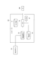
- FIG. 1 is a block diagram illustrating a configuration of an abnormality detection apparatus and peripheral devices according to an embodiment of the present invention.
- an abnormality detection apparatus 102 according to the present embodiment is connected to a robot 101 and a user interface 103 (denoted as “UI” in the figure), and detects an abnormality of the robot 101 (movable apparatus).
- UI user interface
- detecting an abnormality is a concept including predicting not only an abnormality that is currently occurring but also an abnormality that will occur in the future.
- the robot 101 is, for example, a teaching playback type multi-axis robot.
- Teaching playback refers to a function in which an operator actually operates a robot using a teaching pendant attached to the robot, and records and reproduces the operation to operate the robot.
- a teaching playback type robot will be described as an example, but the present invention is not limited to this.
- the robot 101 includes a speed reducer 14, a sensor 13, an operation control unit 12, a disturbance torque calculation unit 15, and a communication unit 11.
- the speed reducer 14 includes a servo motor (hereinafter abbreviated as “motor”) that operates the joint axis of the robot arm, and operates under the control of the operation control unit 12. Then, by operating the speed reducer 14, for example, a welding electrode (welded portion) mounted on the tip of the robot arm is brought into contact with a desired portion of an object to be processed (for example, a metal blank). Carry out welding work. In addition to the welding operation, the robot 101 can perform various operations such as pressing, painting, resin molding, and assembly of the object.
- a servo motor hereinafter abbreviated as “motor”
- a welding electrode welded portion mounted on the tip of the robot arm is brought into contact with a desired portion of an object to be processed (for example, a metal blank). Carry out welding work.
- the robot 101 can perform various operations such as pressing, painting, resin molding, and assembly of the object.
- the disturbance torque calculation unit 15 calculates the disturbance torque generated in each motor provided in the speed reducer 14.
- the disturbance torque indicates a difference between a torque command value for controlling the motor and a detected torque value detected by the sensor 13.
- the difference between the torque command value and the detected torque value is substantially constant, so that the disturbance torque shows a stable numerical value.
- the motor does not operate stably, and a large change occurs in the disturbance torque generated in the motor.
- the processing circuit includes a programmed processing device such as a processing device including an electrical circuit.
- the processing devices also include devices such as application specific integrated circuits (ASICs) and conventional circuit components arranged to perform the functions provided by the robot 101.
- ASICs application specific integrated circuits
- the sensor DB 31 stores each detection signal detected by the sensor 13.
- the detection signals to be stored include each detection signal detected by the sensor 13 when the robot 101 is performing a standard work such as a chip dress operation.
- the detection signals from the sensor 13 are the position and angle of the robot arm, the rotation angle and rotation speed of the motor, the rotation angle of the speed reducer 14, and the like.
- the sensor DB 31 stores the disturbance torque calculated by the disturbance torque calculator 15. That is, the sensor DB 31 has a function as a storage unit that stores a detection signal of the sensor 13 when a routine work is being performed by the robot 101.
- the maintenance DB 33 stores maintenance data when maintenance is performed on the robot 101 when an abnormality occurs in the speed reducer 14 or when an abnormality is predicted.
- the maintenance data can be input by the operator through the user interface 103. Alternatively, when the robot 101 is operated in the above-described maintenance mode, it may be determined that maintenance is being performed, and maintenance data may be automatically created and stored.
- the maintenance data includes the ID number of the reduction gear 14 that has performed maintenance, the date and time of maintenance, and the content of maintenance (exchange, repair, grease renewal, etc.).
- the communication unit 21 communicates with the communication unit 11 provided in the robot 101.
- the operation data of the robot 101 transmitted from the robot 101 is output to the operation history DB 32.
- the detection signal of the sensor 13 transmitted from the robot 101 is received and output to the sensor DB 31. That is, the communication unit 21 has a function as a signal input unit to which a detection signal obtained by detecting the state of the robot 101 (movable device) by the sensor 13 is input.
- the abnormality determination unit 26 acquires the disturbance torque of each motor mounted on the speed reducer 14 of the robot 101 from the sensor DB 31, and an abnormality occurs in the speed reducer 14 that operates with each motor based on the acquired disturbance torque. Determine whether or not. For example, the following abnormalities are calculated.
- the degree of abnormality a (x ') when the disturbance torque is x' is defined by the following equation (1).
- a (x ′) ⁇ (x′ ⁇ m) 2 ⁇ / 2 ⁇ s 2 (1)
- m is a sample average of disturbance torque
- s is a standard deviation of disturbance torque.
- a probability distribution such as kernel density estimation or density ratio estimation can be used as a method for calculating the degree of abnormality.
- the production management device In addition to the method of using the operation data stored in the operation history DB 32, when the robot 101 is connected to the production management device of the factory that performs the work of the object through a communication line, the production management device The operation data of the robot 101 can also be acquired by referring to the time table set in the above.
- the required operation setting unit 25 sets the required operation used by the required operation determination unit 24. At this time, a required operation is individually set for each of the plurality of reduction gears 14 provided.
- the required motion setting unit 25 stores a map that associates the speed reducer 14 with the required motion, such as a rotational angle of 5 ° with respect to the speed reducer A and a rotational angle 15 ° with respect to the speed reducer B. The required operation is set with reference to this map.
- each speed reducer 14 is set to the same operation, and weighting processing set individually for each speed reducer 14 is added (for example, weighting).
- the required operation is calculated by calculation (by multiplying by the coefficient).
- a process for setting a required operation based on disturbance torque data when an abnormality has occurred in the past of each reduction gear 14 is performed.
- the required operation setting unit 25 sets an operation after addition, which is an operation obtained by adding a required operation to a predetermined operation such as a chip dress operation, and transmits it to the robot 101.
- the abnormality detection device 102 can also be realized by using a computer including a CPU 41 (central processing unit), a memory 42, and each database (sensor DB 31, operation history DB 32, maintenance DB 33). .
- a computer program (an abnormality detection program) for causing the computer to function as the abnormality detection apparatus 102 is installed in the computer and executed.
- the CPU 41 functions as a plurality of information processing circuits included in the abnormality detection device 102, that is, the routine work extraction unit 23, the required operation determination unit 24, the required operation setting unit 25, and the abnormality determination unit 26.
- the processing circuit includes a programmed processing device such as a processing device including an electrical circuit.
- the processing device also includes devices such as application specific integrated circuits (ASICs) and conventional circuit components arranged to perform the functions provided by the anomaly detection device 102.
- ASICs application specific integrated circuits
- step S ⁇ b> 11 the routine work extraction unit 23 acquires operation data when the robot 101 is performing a routine work from the operation data stored in the operation history DB 32.
- the abnormality detection apparatus 102 is connected to the production management apparatus via a communication line, the operation data of the robot 101 is acquired with reference to the time table set in the production management apparatus. You can also.
- step S13 the required operation determination unit 24 determines whether or not the above-described required operation is included in the routine work based on the operation data acquired in the process of step S11. Specifically, it is determined whether or not the routine work includes an operation in which the rotation angle of the speed reducer 14 is 15 ° or more.
- step S14 If the required motion is included, it is determined that it is not necessary to add the required motion (“unnecessary” in step S14), and the process proceeds to step S16.
- step S14 if the required operation is not included (“required” in step S14), the process proceeds to step S15.
- step S15 the required operation setting unit 25 sets an operation after addition obtained by adding the required operation to a predetermined operation executed by the speed reducer 14, and outputs a control signal for performing the operation after the addition.
- This control signal is transmitted from the communication unit 21 to the communication unit 11 of the robot 101 and further output to the operation control unit 12.
- step S17 the abnormality determination unit 26 determines whether an abnormality has occurred in the speed reducer 14 using the method described above based on the acquired disturbance torque.
- the degree of abnormality is calculated using the above-described equation (1), and when the calculated degree of abnormality exceeds a threshold value, it is determined that the speed reducer 14 is abnormal.
- step S18 the operator is notified that an abnormality has occurred in the speed reducer 14. For example, an image indicating the occurrence of an abnormality is displayed on a display (not shown) provided in the user interface 103. In this way, the abnormality of the speed reducer 14 mounted on the robot 101, and hence the abnormality of the robot 101 can be detected.
- the abnormality detection device 102 can achieve the following effects.
- the required motion setting unit 25 is used to operate the speed reducer 14 when the robot 101 (movable device) performs a standard work such as a tip dress operation (a predetermined motion that does not work on an object).
- the post-addition operation is set by adding a required operation (for example, an operation in which the gear rotation angle of the speed reducer 14 is 15 °) that is necessary for detecting the abnormality. Then, a control signal for causing the robot 101 to perform the post-addition operation is output. Therefore, the required operation is included in the operation when the robot 101 performs the standard work.
- the required motion setting unit 25 sets the post-addition motion only when the above-mentioned required motion is not included in the motion of the speed reducer 14 when the robot 101 executes the standard work, and adds the motion to the robot 101.
- a control signal for performing the post-operation is output. Therefore, when the required work is included in the routine work, the post-addition action is not set, so that it is possible to avoid adding an unnecessary action to the routine work.
- step S14a is added, so the process of step S14a will be described below.
- step S14 when the required motion determination unit 24 determines that the required motion needs to be added, the required motion setting unit 25 performs the weighting process according to each speed reducer 14 in step S14a. To do.
- the rotation angle of the speed reducer 14 is set to 15 °. That is, the required operation is weighted according to the magnitude of the load connected to the speed reducer 14.
- size of the load of the reduction gear 14 includes the torque which drives a load, the power consumption of the motor connected to the reduction gear 14, an energization current, etc.
- step S15 the required operation setting unit 25 sets the post-addition operation by adding the required operation to the predetermined operation executed by the speed reducer 14, and this post-addition operation A control signal for performing the operation is output.
- the processing after step S15 is the same as that of the first embodiment shown in FIG.
- the routine work extraction unit 23 uses the past disturbance torque data stored in the sensor DB 31 when the speed reducer 14 to be subjected to abnormality determination is performing a routine work. Obtain disturbance torque data. Further, maintenance data when maintenance is performed due to an abnormality in the reduction gear 14 is acquired from the maintenance data stored in the maintenance DB 33.
- the target movable device for detecting an abnormality is not limited to the robot 101.
- an automobile engine may be used instead of the motor, and a transmission may be used instead of the speed reducer 14.
- a moving body such as a rotating mechanism of a moving body, a moving body such as an amusement park playground equipment, a machine tool such as a three-dimensional printer, that is, all movable devices having a rotating mechanism and a mechanism for transmitting the rotating mechanism can be used.
- other types of movable devices may be targeted.
- the abnormality detection device 102 may be arranged at a remote location, and necessary signals and data may be transmitted / received via a communication line to detect an abnormality of the robot 101 (movable device).
- abnormality detection of a plurality of robots may be performed by one abnormality detection device 102. Further, the plurality of robots may be arranged at different locations.
Abstract
対象物に対して溶接等の作業を行うロボット(101)の異常を検出する異常検出装置であって、センサ(13)によってロボット(101)の状態を検出した検出信号が入力される信号入力部を含み、検出信号に基づいて、ロボット(101)の異常を検出する制御部(51)を備える。制御部(51)は、対象物に対して作業を行わない所定の動作に、異常を検出するために必要な動作である所要動作を加えた加算後動作を行わせるための制御信号をロボット(101)に出力する。そして、加算後動作が実行されたときに検出された検出信号に基づいて、ロボット(101)の異常を検出する。
Description
本発明は、多軸型ロボット等の可動装置の異常を検出する異常検出装置及び異常検出方法に関するものである。
従来より、多関節型の産業用ロボットの異常検出装置として、特許文献1に開示されたものが知られている。特許文献1では、ロボットの動作中において所定周期毎にロボット関節軸の移動位置及び関節軸に加えられる外乱トルクを検出し、検出された移動位置毎の外乱トルクの平均値を算出する。そして、算出した平均値と所定の閾値とを比較し、平均値が閾値を超えている場合に、ロボットが異常であると判断する。
しかしながら、ロボットによる定型作業によっては、関節軸の動きが小さく外乱トルクへの影響が小さくなり、異常検出に必要な外乱トルクの変化を検出できない場合がある。特許文献1では、ロボットによる作業の内容を考慮せずに一定の閾値と外乱トルクとを比較しているため、外乱トルクの変化が小さい場合には、異常の発生を見逃してしまい、正確な異常検出ができないという問題があった。
本発明は、このような従来の課題を解決するためになされたものであり、その目的とするところは、可動装置の動きが小さい場合であっても、可動装置の異常を高精度に検出することが可能な異常検出装置及び異常検出方法を提供することにある。
本発明の一態様は、センサによって可動装置の状態を検出した検出信号が入力される信号入力部を含み、検出信号に基づいて、可動装置の異常を検出する制御部を備える。制御部は、対象物に対して作業を行わない所定の動作に所要動作を加えた加算後動作を行わせるための制御信号を可動装置に出力する。加算後動作の実行時に検出された検出信号に基づいて、可動装置の異常を検出する。
本発明の一態様によれば、可動装置の動きが小さい場合であっても、可動装置の異常を高精度に検出することが可能になる。
以下、本発明の実施形態について図面を参照して説明する。
[第1実施形態の説明]
図1は、本発明の実施形態に係る異常検出装置、及びその周辺機器の構成を示すブロック図である。図1に示すように、本実施形態に係る異常検出装置102は、ロボット101、及びユーザインターフェース103(図では「UI」と表記)に接続されており、ロボット101(可動装置)の異常を検出する。なお、「異常を検出する」とは、現在生じている異常のみならず、将来的に発生する異常を予測することを含む概念である。
図1は、本発明の実施形態に係る異常検出装置、及びその周辺機器の構成を示すブロック図である。図1に示すように、本実施形態に係る異常検出装置102は、ロボット101、及びユーザインターフェース103(図では「UI」と表記)に接続されており、ロボット101(可動装置)の異常を検出する。なお、「異常を検出する」とは、現在生じている異常のみならず、将来的に発生する異常を予測することを含む概念である。
ロボット101は、例えばティーチングプレイバック型の多軸型ロボットである。ティーチングプレイバックとは、ロボットに付属するティーチングペンダントを使用して、操作者がロボットを実際に動作させ、その動作を記録、再生させてロボットを動作させる機能を示す。なお、本実施形態では、ティーチングプレイバック型のロボットを例に挙げて説明するが、本発明はこれに限定されるものではない。
ロボット101は、減速機14と、センサ13と、動作制御部12と、外乱トルク演算部15と、通信部11を備えている。
減速機14は、ロボットアームの関節軸を動作するサーボモータ(以下、「モータ」と略す)を備えており、動作制御部12の制御により動作する。そして、減速機14を動作させることにより、例えばロボットアームの先端に搭載した溶接電極(溶接部)を、加工の対象となる対象物(例えば、金属製のブランク材)の所望部位に接触させて、溶接作業を実施する。また、溶接作業以外にも、ロボット101により、対象物のプレス、塗装、樹脂成形、組み立て、等の各種作業を実施することができる。
センサ13は、例えばパルスジェネレータやエンコーダ等を含み、減速機14により動作するロボットアームの位置及び角度、モータの回転角度、回転速度、消費電力、及び電流、減速機14の回転角度等の各種の物理量を検出する。更に、センサ13は、各モータに生じるトルク値を検出する。また、センサ13は、ロボット101が対象物に対して作業(例えば、溶接)を行うとき、及び対象物に対して作業を行わない動作である定型作業(所定の動作)を行うときにおいて、上記の物理量を検出する。センサ13で検出した検出信号(可動装置の状態を検出した検出信号)は、通信部11より異常検出装置102に送信される。
動作制御部12は、上述したティーチングにより設定された動作プログラムに従って減速機14を動作させ、ロボット101に搭載される各ロボットアーム、関節軸が所望の動作をするように制御する。また、後述するように、異常検出装置102より、減速機14に発生する異常を検出するための加算後動作の実行を指示する制御信号が与えられた場合には、この加算後動作を実行するように、減速機14を制御する。
外乱トルク演算部15は、減速機14に設けられる各モータに発生する外乱トルクを演算する。外乱トルクとは、モータを制御する際のトルク指令値と、センサ13で検出されるトルク検出値との差分を示す。減速機14が正常でありモータが安定的に動作しているときは、トルク指令値とトルク検出値との差分はほぼ一定となるので、外乱トルクは安定した数値を示す。減速機14に異常が発生している場合にはモータは安定的に動作せず、モータに生じる外乱トルクに大きな変化が発生する。
通信部11は、ロボット101の稼働データ、外乱トルク等の各種データを異常検出装置102に送信する。また、異常検出装置102より、加算後動作(後述)の実行を指示する制御信号が送信された場合には、これを受信して動作制御部12に出力する。
ロボット101が備える上記した各機能は、1又は複数の処理回路により実装され得る。処理回路は、電気回路を含む処理装置等のプログラムされた処理装置を含む。処理装置は、また、ロボット101が備える機能を実行するようにアレンジされた特定用途向け集積回路(ASIC)や従来型の回路部品のような装置を含む。
次に、異常検出装置102の構成を説明する。異常検出装置102は、通信部21と、制御部51と、各種のデータベース(DB)を備えている。制御部51は、定型作業抽出部23と、所要動作判定部24と、所要動作設定部25と、異常判断部26を含んでいる。データベースは、センサDB31と、稼働履歴DB32と、保全DB33を含んでいる。
センサDB31は、センサ13で検出された各検出信号を記憶する。記憶する検出信号には、ロボット101がチップドレス動作等の定型作業を実行しているときの、センサ13で検出された各検出信号が含まれる。上述したようにセンサ13による検出信号は、ロボットアームの位置及び角度、モータの回転角度及び回転速度、減速機14の回転角度等である。また、センサDB31は、外乱トルク演算部15で算出された外乱トルクを記憶する。即ち、センサDB31は、ロボット101にて定型作業が実行されているときの、センサ13の検出信号を記憶する記憶部としての機能を備えている。
稼働履歴DB32は、ロボット101の稼働データを記憶する。稼働データには、ロボット101の稼働日、稼働を開始した時刻、稼働を停止した時刻、連続して稼働した時間、連続して停止した時間等の、稼働に関する各種のデータが含まれる。また、稼働データには、減速機14の運転モードが含まれる。運転モードには、通常運転モード、保全モード、停止モードが含まれる。
保全DB33は、減速機14に異常が発生した場合や、異常の発生が予測された場合において、ロボット101に対して保全を実施した際の、保全データを記憶する。保全データは、操作者がユーザインターフェース103により入力することができる。或いは、ロボット101が上述した保全モードで運転された場合に、保全が実施されているものと判断して自動で保全データを作成して記憶してもよい。保全データには、保全を実施した減速機14のID番号、保全を実施した日時、保全の内容(交換、修理、グリスの更油等)が含まれる。
通信部21は、ロボット101に設けられる通信部11との間で通信を行う。ロボット101より送信されるロボット101の稼働データを稼働履歴DB32に出力する。また、ロボット101より送信されるセンサ13の検出信号を受信して、センサDB31に出力する。即ち、通信部21は、センサ13によってロボット101(可動装置)の状態を検出した検出信号が入力される信号入力部としての機能を備えている。
異常判断部26は、ロボット101の減速機14に搭載される各モータの外乱トルクを、センサDB31から取得し、取得した外乱トルクに基づいて各モータで動作する減速機14に異常が発生しているか否かを判断する。例えば、以下に示す異常度を算出する。
外乱トルクがx’であるときの異常度a(x’)を、下記の(1)式で定義する。
a(x’)={(x’-m)2}/2・s2 ・・・(1)
但し、mは外乱トルクの標本平均、sは外乱トルクの標準偏差である。
但し、mは外乱トルクの標本平均、sは外乱トルクの標準偏差である。
そして、異常度a(x’)が所定の閾値を上回ったときに、減速機14は異常であると判断する。また、上記以外にも、異常度を算出する手法として、カーネル密度推定や密度比推定等の確率分布を用いることができる。
更に、その他の異常判断の方法として、外乱トルクと所定の基準値との差分を演算し、更に、この差分の時間経過に対する変化率を算出する。そして、変化率が所定の閾値を上回った場合に減速機14は異常であると判断することもできる。所定の基準値は、1年前の同月の外乱トルクの平均値を用いることができる。
定型作業抽出部23は、稼働履歴DB32に記憶されているロボット101の稼働データに基づき、ロボット101が定型作業(所定の動作)を実行している時間帯の稼働データを抽出する。定型作業とは、ロボット101(可動装置)が、加工の対象物に対して作業を行わない動作のことである。例えば、ロボット101がブランク材等の加工の対象物に溶接を実行した後に、溶接電極の表面に付着した汚れを除去する動作(チップドレス動作)である。
また、稼働履歴DB32に記憶されている稼働データを利用する方法以外にも、ロボット101が、対象物の作業を行う工場の生産管理装置に通信回線で接続されている場合には、生産管理装置に設定されているタイムテーブルを参照して、ロボット101の稼働データを取得することもできる。
所要動作判定部24は、定型作業抽出部23で抽出した定型作業の稼働データに基づいて、定型作業の動作内に、減速機14の異常を検出するために必要な動作である所要動作が含まれているか否かを判断する。即ち、上述した異常判断部26で減速機14が異常であるか否かを判断するためには、定型作業中のモータの回転角度、即ち、モータで動作する減速機14の回転角度がある程度大きいことが必要である。例えば、減速機14の回転角度が15°以上動作することが必要である。所要動作判定部24では、このような所要動作が定型動作内に含まれているか否かを判断する。また、減速機14の回転角度以外にも、ロボットアームの位置の変化量等を用いることもできる。
所要動作設定部25は、所要動作判定部24で用いる所要動作を設定する。この際、複数設けられる各減速機14毎にそれぞれ個別に所要動作を設定する。例えば、所要動作設定部25は、減速機Aに対して回転角度を5°、減速機Bに対して回転角度15°のように、減速機14と所要動作を対応づけるマップを記憶しており、このマップを参照して所要動作を設定する。
また、後述する第2実施形態にて示すように、各減速機14の所要動作を同一の動作に設定しておき、各減速機14毎に個別に設定した重み付け処理を加えて(例えば、重み付けの係数を乗じて)所要動作を演算により算出する処理を行う。更に、後述する第3実施形態にて示すように、各減速機14の過去に異常が発生したときの外乱トルクデータに基づいて所要動作を設定する処理を行う。
所要動作は、定型作業に付随する動作であっても、或いは、定型作業に関係のないダミー動作であっても良い。所要動作は、対象物に対して作業(例えば、溶接)を行わないチップドレス動作等の定型作業(所定の動作)に加えるので、対象物に対する作業に影響を与えることはない。
更に所要動作設定部25は、チップドレス動作等の所定の動作に、所要動作を加えた動作である加算後動作を設定して、ロボット101に送信する。
ここで、異常検出装置102は、図2に示すようにCPU41(中央処理装置)、メモリ42、及び各データベース(センサDB31、稼働履歴DB32、保全DB33)を備えるコンピュータを用いて実現することもできる。コンピュータを異常検出装置102として機能させるためのコンピュータプログラム(異常検出プログラム)を、コンピュータにインストールして実行する。これにより、CPU41は、異常検出装置102が備える複数の情報処理回路、即ち、定型作業抽出部23、所要動作判定部24、所要動作設定部25、異常判断部26として機能する。
異常検出装置102が備える上記した各機能は、1又は複数の処理回路により実装され得る。処理回路は、電気回路を含む処理装置等のプログラムされた処理装置を含む。処理装置は、また、異常検出装置102が備える機能を実行するようにアレンジされた特定用途向け集積回路(ASIC)や従来型の回路部品のような装置を含む。
次に、第1実施形態に係る異常検出装置102の処理手順を、図3に示すフローチャートを参照して説明する。
初めに、ステップS11において、定型作業抽出部23は、稼働履歴DB32に記憶されている稼働データから、ロボット101が定型作業を実施しているときの稼働データを取得する。なお、前述したように、異常検出装置102が生産管理装置に通信回線で接続されている場合には、生産管理装置に設定されているタイムテーブルを参照して、ロボット101の稼働データを取得することもできる。
ステップS12において、所要動作設定部25は、減速機14の異常検出に必要な所要動作を設定する。前述したように、所要動作設定部25は、各減速機14と所要動作を対応させたマップを記憶しており、このマップを参照することにより、所要動作を設定することができる。例えば、減速機14の異常を検出するために必要な回転角度が15°である場合には、この回転角度を15°を所要動作として設定する。
ステップS13において、所要動作判定部24は、ステップS11の処理で取得した稼働データに基づいて、定型作業内に上記の所要動作が含まれているか否かを判断する。具体的には、減速機14の回転角度が15°以上となる動作が定型作業に含まれているか否かを判断する。
所要動作が含まれている場合には、所要動作の追加は不要と判断し(ステップS14で「不要」)、ステップS16に処理を進める。
一方、所要動作が含まれていない場合には(ステップS14で「必要」)、ステップS15に処理を進める。
ステップS15において、所要動作設定部25は、減速機14により実行される所定の動作に所要動作を加えた加算後動作を設定し、この加算後動作を行わせるための制御信号を出力する。この制御信号は、通信部21からロボット101の通信部11に送信され、更に、動作制御部12に出力される。
動作制御部12は、制御信号に基づいて、減速機14を15°だけ回転させる動作(加算後動作)を実行する制御を行う。或いは、定型作業内に例えば減速機14を5°回転させる動作が存在する場合に、この動作において、減速機14を15°回転させる動作(加算後動作)に変更する。こうすることにより、定型作業に所要動作を含ませることができる。
ステップS16において、異常判断部26は、上記の所要動作が追加された加算後動作が実行されているときの外乱トルクを取得する。
ステップS17において、異常判断部26は、取得した外乱トルクに基づき、上述した方法を用いて、減速機14に異常が発生しているか否かを判断する。例えば、前述した(1)式を用いて異常度を算出し、算出した異常度が閾値を超えた場合に、減速機14は異常であると判断する。
異常であると判断した場合には(ステップS17でYES)、ステップS18において、減速機14に異常が発生したことを操作者に報知する。例えば、ユーザインターフェース103に設けられたディスプレイ(図示省略)に異常の発生を示す画像を表示する。こうして、ロボット101に搭載される減速機14の異常、ひいてはロボット101の異常を検出できるのである。
このようにして、第1実施形態に係る異常検出装置102では、以下に示す効果を達成できる。
(1)
所要動作設定部25は、ロボット101(可動装置)がチップドレス動作等の定型作業(対象物に対して作業を行わない所定の動作)を実行する際の減速機14の動作に、減速機14の異常を検出するために必要な動作である所要動作(例えば、減速機14のギヤの回転角度が15°となる動作)を加えた加算後動作を設定する。そして、ロボット101に加算後動作を行わせるための制御信号を出力する。従って、ロボット101が定型作業を実施する際の動作に、上記の所要動作が含まれることになる。定型作業抽出部23が、加算後動作が実行されたときの外乱トルク(検出信号)を検出することにより、減速機14の異常、ひいてはロボット101の異常(可動装置の異常)を高精度に検出することができる。
所要動作設定部25は、ロボット101(可動装置)がチップドレス動作等の定型作業(対象物に対して作業を行わない所定の動作)を実行する際の減速機14の動作に、減速機14の異常を検出するために必要な動作である所要動作(例えば、減速機14のギヤの回転角度が15°となる動作)を加えた加算後動作を設定する。そして、ロボット101に加算後動作を行わせるための制御信号を出力する。従って、ロボット101が定型作業を実施する際の動作に、上記の所要動作が含まれることになる。定型作業抽出部23が、加算後動作が実行されたときの外乱トルク(検出信号)を検出することにより、減速機14の異常、ひいてはロボット101の異常(可動装置の異常)を高精度に検出することができる。
(2)
また、所要動作設定部25は、ロボット101が定型作業を実行する際の減速機14の動作に、上記の所要動作が含まれていない場合に限って加算後動作を設定し、ロボット101に加算後動作を行わせるための制御信号を出力する。従って、定型作業に所要動作が含まれている場合には、加算後動作を設定しないので、定型作業に不要な動作を追加することを回避できる。
また、所要動作設定部25は、ロボット101が定型作業を実行する際の減速機14の動作に、上記の所要動作が含まれていない場合に限って加算後動作を設定し、ロボット101に加算後動作を行わせるための制御信号を出力する。従って、定型作業に所要動作が含まれている場合には、加算後動作を設定しないので、定型作業に不要な動作を追加することを回避できる。
(3)
所要動作設定部25は、ロボット101に搭載される各減速機14と、各減速機14の異常を検出するための所要動作との対応を示すマップを記憶しており、該マップを参照して所要動作を設定するので、異常検出の対象となる減速機14の加算後動作を容易に設定することが可能となる。
所要動作設定部25は、ロボット101に搭載される各減速機14と、各減速機14の異常を検出するための所要動作との対応を示すマップを記憶しており、該マップを参照して所要動作を設定するので、異常検出の対象となる減速機14の加算後動作を容易に設定することが可能となる。
(4)
所要動作設定部25は、ロボット101の異常を検出する為に定型作業に追加する所要動作を、減速機14の回転動作とするので、減速機14を駆動するモータの外乱トルクの変化を検出することにより、容易に異常判定することが可能となる。
所要動作設定部25は、ロボット101の異常を検出する為に定型作業に追加する所要動作を、減速機14の回転動作とするので、減速機14を駆動するモータの外乱トルクの変化を検出することにより、容易に異常判定することが可能となる。
(5)
ロボット101により実施される作業が溶接作業であり、溶接作業を行わない所定の動作を、溶接電極の汚れを除去する動作(チップドレス動作)としているので、外乱トルク演算部15は、ロボット101が加算後動作を実施しているときのモータに生じる外乱トルクを高精度に検出することができ、ロボット101に生じる異常検出の精度を向上させることができる。
ロボット101により実施される作業が溶接作業であり、溶接作業を行わない所定の動作を、溶接電極の汚れを除去する動作(チップドレス動作)としているので、外乱トルク演算部15は、ロボット101が加算後動作を実施しているときのモータに生じる外乱トルクを高精度に検出することができ、ロボット101に生じる異常検出の精度を向上させることができる。
[第2実施形態の説明]
次に、本発明の第2実施形態について説明する。装置構成は第1実施形態で示した図1と同様であるので説明を省略する。第2実施形態では、定型作業に所要動作を追加する際に、ロボット101に設けられる各減速機14毎に所要動作に重み付け処理を加える点で、前述した第1実施形態と相違する。以下、図4に示すフローチャートを参照して、第2実施形態に係る異常検出装置の処理手順について説明する。
次に、本発明の第2実施形態について説明する。装置構成は第1実施形態で示した図1と同様であるので説明を省略する。第2実施形態では、定型作業に所要動作を追加する際に、ロボット101に設けられる各減速機14毎に所要動作に重み付け処理を加える点で、前述した第1実施形態と相違する。以下、図4に示すフローチャートを参照して、第2実施形態に係る異常検出装置の処理手順について説明する。
図4に示すフローチャートでは前述した図3のフローチャートと対比して、ステップS14aの処理を加えた点で相違するので、以下、ステップS14aの処理について説明する。
ステップS14の処理で、所要動作判定部24が、所要動作の追加が必要であると判断した場合には、ステップS14aにおいて、所要動作設定部25は、各減速機14に応じて重み付け処理を実施する。
例えば、大きい負荷が接続される減速機14では、減速機14の回転角度が小さくてもモータには大きな外乱トルクが発生するので、減速機14の異常を検出できる。従って、減速機14の回転角度は小さくてもよく、例えば、減速機14の回転角度を5°に設定する。
一方、上記の負荷よりも相対的に小さい負荷が接続される減速機14では、減速機14の回転角度が小さいと、モータに発生する外乱トルクは大きく変化せず、減速機14の異常を検出できない。従って、減速機14の回転角度を大きくする必要があり、例えば減速機14の回転角度を15°に設定する。即ち、減速機14に接続される負荷の大きさに応じて、所要動作の重み付け処理を行う。なお、減速機14の負荷の大きさには、負荷を駆動するトルク、減速機14に接続されるモータの消費電力、通電電流等が含まれる。
その後、前述した第1実施形態と同様に、ステップS15において、所要動作設定部25は、減速機14により実行される所定の動作に所要動作を加えた加算後動作を設定し、この加算後動作を行わせるための制御信号を出力する。ステップS15以後の処理は図3で示した第1実施形態と同様であるので、説明を省略する。
このように、第2実施形態に係る異常検出装置では、異常検出の対象となる減速機14に接続される負荷の大きさに応じて、異常検出を行うために追加する動作(所要動作)の重み付け処理を行う。従って、異常を検出するために必要となる最小限の動作を求めることができ、所要動作を必要以上に大きくすることを回避することができる。このため、加算後動作を最小限に抑えて、減速機14の異常、ひいてはロボット101の異常を検出することができる。
[第3実施形態の説明]
次に、本発明の第3実施形態について説明する。装置構成は第1実施形態で示した図1と同様であるので説明を省略する。第3実施形態では、過去に実行したチップドレス等の定型作業において検出された外乱トルクの波形に基づいて、所要動作を設定する点で、前述した第1実施形態と相違する。以下、図5に示すフローチャートを参照して、第3実施形態に係る異常検出装置の処理手順について説明する。
次に、本発明の第3実施形態について説明する。装置構成は第1実施形態で示した図1と同様であるので説明を省略する。第3実施形態では、過去に実行したチップドレス等の定型作業において検出された外乱トルクの波形に基づいて、所要動作を設定する点で、前述した第1実施形態と相違する。以下、図5に示すフローチャートを参照して、第3実施形態に係る異常検出装置の処理手順について説明する。
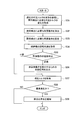
初めに、ステップS31の処理において、定型作業抽出部23は、センサDB31に記憶されている過去の外乱トルクデータから、異常判定の対象となる減速機14が定型作業を実行しているときの、外乱トルクデータを取得する。更に、保全DB33に記憶されている保全データから、減速機14に異常が発生して保全を実施したときの保全データを取得する。
ステップS32において、定型作業抽出部23は、減速機14に異常が発生したときの外乱トルクの変化を検出し、異常判定に必要な減速機14の所要動作(この例では、減速機14の回転角度)を求める。具体的には、過去に減速機14に異常が発生したときにおいて、減速機14の回転角度が15°未満の場合には外乱トルクの変化が小さく、回転角度が15°を超えた場合に外乱トルクの変化が大きい、というデータがセンサDB31に記憶されている場合には、異常判定に必要な減速機14の回転角度は15°であると判断する。
ステップS33において、所要動作設定部25は、所要動作を設定する。例えば、減速機14の回転角度を15°を所要動作として設定する。そして、ステップS34~S39の処理を実行して、減速機14の異常を判断する。
ステップS34~S39の処理は、図3に示したステップS13~S18と同様の処理であるので説明を省略する。
このように、第3実施形態に係る異常検出装置では、所要動作設定部25は、減速機14のモータに発生した過去の外乱トルクに基づいて所要動作を求めるので、所要動作を必要以上に大きくすることを回避することができる。このため、加算後動作を最小限に抑えて、減速機14の異常、ひいてはロボット101の異常を検出することが可能となる。
なお、異常を検出する対象の可動装置はロボット101に限定されるものでない。例えば、モータの代わりに自動車のエンジン、減速機14の代わりにトランスミッションを用いてもよい。また、移動体の回転機構、遊園地の遊具などの移動体、3次元プリンターなどの工作機械、即ち、回転機構とそれを伝達する機構を有する全ての可動装置も対象にすることができる。また、その他の種類の可動装置を対象としてもよい。
また、異常検出装置102を遠隔地に配置し、必要な信号やデータを通信回線を介して送受信して、ロボット101(可動装置)の異常を検出してもよい。また、複数のロボットの異常検出を1台の異常検出装置102で行ってもよい。また、複数のロボットは互いに異なる場所に配置されていてもよい。
以上、本発明の実施形態を記載したが、この開示の一部をなす論述及び図面はこの発明を限定するものであると理解すべきではない。この開示から当業者には様々な代替実施の形態、実施例及び運用技術が明らかとなろう。
11 通信部
12 動作制御部
13 センサ
14 減速機
15 外乱トルク演算部
23 定型作業抽出部
24 所要動作判定部
25 所要動作設定部
26 異常判断部
31 センサDB(記憶部)
32 稼働履歴DB
33 保全DB
51 制御部
101 ロボット(可動装置)
102 異常検出装置
103 ユーザインターフェース
12 動作制御部
13 センサ
14 減速機
15 外乱トルク演算部
23 定型作業抽出部
24 所要動作判定部
25 所要動作設定部
26 異常判断部
31 センサDB(記憶部)
32 稼働履歴DB
33 保全DB
51 制御部
101 ロボット(可動装置)
102 異常検出装置
103 ユーザインターフェース
Claims (8)
- 対象物に対して作業を行う可動装置の異常を検出する異常検出装置であって、
センサによって前記可動装置の状態を検出した検出信号が入力される信号入力部を含み、前記検出信号に基づいて、前記可動装置の異常を検出する制御部、を備え、
前記制御部は、
前記対象物に対して作業を行わない所定の動作に、前記異常を検出するために必要な動作である所要動作を加えた加算後動作を行わせるための制御信号を前記可動装置に出力し、
前記加算後動作が実行されたときに検出された前記検出信号に基づいて、前記可動装置の異常を検出すること
を特徴とする異常検出装置。 - 前記制御部は、前記所定の動作に前記所要動作が含まれない場合に限り、前記制御信号を出力すること
を特徴とする請求項1に記載の異常検出装置。 - 前記所定の動作が実行されているときに検出された検出信号を記憶する記憶部を更に備え、
前記制御部は、前記記憶部に記憶されている過去の前記検出信号に基づいて、前記所要動作を設定すること
を特徴とする請求項1または2に記載の異常検出装置。 - 前記可動装置は、複数の減速機を備え、
前記制御部は、前記各減速機と、各減速機に対応して設定した前記所要動作との対応を示すマップを参照して、各減速機に対する前記所要動作を設定すること
を特徴とする請求項1~3のいずれか1項に記載の異常検出装置。 - 前記可動装置は、減速機を備え、
前記制御部は、前記減速機に接続される負荷の大きさに基づいて、前記所要動作を設定すること
を特徴とする請求項1~3のいずれか1項に記載の異常検出装置。 - 前記可動装置は、減速機を備え、
前記所要動作は、前記減速機の回転動作であることを特徴とする請求項1~5のいずれか1項に記載の異常検出装置。 - 前記作業は、前記対象物に対する溶接作業であり、
前記所定の動作は、前記溶接作業を実施する溶接部の汚れを除去する動作であることを特徴とする請求項1~6のいずれか1項に記載の異常検出装置。 - 対象物に対して作業を行う可動装置の異常を検出する異常検出方法であって、
前記可動装置が、前記対象物に対して作業を行わない所定の動作に、前記異常を検出するために必要な動作である所要動作を加えた加算後動作を行わせるための制御信号を前記可動装置に出力し、
前記加算後動作が実行されたときに、センサによって前記可動装置の状態を検出した検出信号を取得し、
取得した前記検出信号に基づいて、前記可動装置の異常を検出すること
を特徴とする異常検出方法。
Priority Applications (5)
| Application Number | Priority Date | Filing Date | Title |
|---|---|---|---|
| EP18917815.5A EP3792017A4 (en) | 2018-05-11 | 2018-05-11 | ANOMALY DETECTION DEVICE AND ANOMALY DETECTION METHOD |
| CN201880093355.6A CN112105489B (zh) | 2018-05-11 | 2018-05-11 | 异常检测装置和异常检测方法 |
| US17/054,344 US11820007B2 (en) | 2018-05-11 | 2018-05-11 | Abnormality detection device and abnormality detection method |
| JP2020517733A JP7056733B2 (ja) | 2018-05-11 | 2018-05-11 | 異常検出装置及び異常検出方法 |
| PCT/JP2018/018313 WO2019215909A1 (ja) | 2018-05-11 | 2018-05-11 | 異常検出装置及び異常検出方法 |
Applications Claiming Priority (1)
| Application Number | Priority Date | Filing Date | Title |
|---|---|---|---|
| PCT/JP2018/018313 WO2019215909A1 (ja) | 2018-05-11 | 2018-05-11 | 異常検出装置及び異常検出方法 |
Publications (1)
| Publication Number | Publication Date |
|---|---|
| WO2019215909A1 true WO2019215909A1 (ja) | 2019-11-14 |
Family
ID=68466917
Family Applications (1)
| Application Number | Title | Priority Date | Filing Date |
|---|---|---|---|
| PCT/JP2018/018313 WO2019215909A1 (ja) | 2018-05-11 | 2018-05-11 | 異常検出装置及び異常検出方法 |
Country Status (5)
| Country | Link |
|---|---|
| US (1) | US11820007B2 (ja) |
| EP (1) | EP3792017A4 (ja) |
| JP (1) | JP7056733B2 (ja) |
| CN (1) | CN112105489B (ja) |
| WO (1) | WO2019215909A1 (ja) |
Citations (4)
| Publication number | Priority date | Publication date | Assignee | Title |
|---|---|---|---|---|
| JPH09174482A (ja) | 1995-12-25 | 1997-07-08 | Fanuc Ltd | ロボットの故障診断方法 |
| WO2016185593A1 (ja) * | 2015-05-21 | 2016-11-24 | 日産自動車株式会社 | 故障診断装置及び故障診断方法 |
| JP2017061001A (ja) * | 2015-09-24 | 2017-03-30 | キヤノン株式会社 | ロボット装置の診断方法、ロボット装置の制御プログラム、およびロボットシステム |
| JP2017200710A (ja) * | 2016-05-02 | 2017-11-09 | トヨタ自動車株式会社 | 関節駆動ロボットの異常診断方法及び異常診断装置 |
Family Cites Families (15)
| Publication number | Priority date | Publication date | Assignee | Title |
|---|---|---|---|---|
| JPH026081A (ja) * | 1988-06-24 | 1990-01-10 | Nissan Motor Co Ltd | 車体組立装置の異常検知方法 |
| JP4391381B2 (ja) * | 2004-10-06 | 2009-12-24 | 株式会社安川電機 | 多関節ロボットの減速機の異常判定装置及び多関節ロボットの減速機の異常判定方法 |
| JP2006281421A (ja) | 2005-04-05 | 2006-10-19 | Yaskawa Electric Corp | ロボットおよびロボットの異常検出方法 |
| JP2012139772A (ja) * | 2010-12-28 | 2012-07-26 | Yaskawa Electric Corp | ロボットシステム及びロボットの異常検出方法 |
| JP5365595B2 (ja) * | 2010-09-15 | 2013-12-11 | 株式会社安川電機 | 減速機の異常判定方法、異常判定装置、ロボット及びロボットシステム |
| EP2913163B1 (en) * | 2012-10-25 | 2019-10-09 | Panasonic Intellectual Property Management Co., Ltd. | Robot malfunction indication method |
| JP6174906B2 (ja) * | 2013-05-23 | 2017-08-02 | 中村留精密工業株式会社 | 機械の自己診断及び機械精度の補正方法 |
| JP5926344B2 (ja) * | 2014-09-22 | 2016-05-25 | ファナック株式会社 | 非常停止時のロボットに関する不具合を防止するロボット制御装置 |
| JP6402825B2 (ja) * | 2015-05-22 | 2018-10-10 | 日産自動車株式会社 | 故障診断装置及び故障診断方法 |
| MY167713A (en) | 2015-05-29 | 2018-09-21 | Nissan Motor | Failure diagnosis device and failure diagnosis method |
| EP3342561B1 (en) * | 2015-08-25 | 2022-08-10 | Kawasaki Jukogyo Kabushiki Kaisha | Remote control robot system |
| JP6392819B2 (ja) * | 2016-08-23 | 2018-09-19 | ファナック株式会社 | 製造時間情報により異常検出条件を変更する製造管理システム |
| JP6857818B2 (ja) * | 2016-10-24 | 2021-04-14 | パナソニックIpマネジメント株式会社 | エンコーダの異常検出方法及び異常検出装置、並びにロボット制御システム |
| WO2019167171A1 (ja) * | 2018-02-28 | 2019-09-06 | 日産自動車株式会社 | 異常検出装置及び異常検出方法 |
| US11433539B2 (en) * | 2018-07-31 | 2022-09-06 | Nissan Motor Co., Ltd. | Abnormality determination device and abnormality determination method |
-
2018
- 2018-05-11 CN CN201880093355.6A patent/CN112105489B/zh active Active
- 2018-05-11 US US17/054,344 patent/US11820007B2/en active Active
- 2018-05-11 EP EP18917815.5A patent/EP3792017A4/en active Pending
- 2018-05-11 WO PCT/JP2018/018313 patent/WO2019215909A1/ja active Application Filing
- 2018-05-11 JP JP2020517733A patent/JP7056733B2/ja active Active
Patent Citations (4)
| Publication number | Priority date | Publication date | Assignee | Title |
|---|---|---|---|---|
| JPH09174482A (ja) | 1995-12-25 | 1997-07-08 | Fanuc Ltd | ロボットの故障診断方法 |
| WO2016185593A1 (ja) * | 2015-05-21 | 2016-11-24 | 日産自動車株式会社 | 故障診断装置及び故障診断方法 |
| JP2017061001A (ja) * | 2015-09-24 | 2017-03-30 | キヤノン株式会社 | ロボット装置の診断方法、ロボット装置の制御プログラム、およびロボットシステム |
| JP2017200710A (ja) * | 2016-05-02 | 2017-11-09 | トヨタ自動車株式会社 | 関節駆動ロボットの異常診断方法及び異常診断装置 |
Non-Patent Citations (1)
| Title |
|---|
| See also references of EP3792017A4 |
Also Published As
| Publication number | Publication date |
|---|---|
| CN112105489B (zh) | 2023-06-20 |
| US20210191346A1 (en) | 2021-06-24 |
| EP3792017A1 (en) | 2021-03-17 |
| CN112105489A (zh) | 2020-12-18 |
| JP7056733B2 (ja) | 2022-04-19 |
| JPWO2019215909A1 (ja) | 2021-05-27 |
| US11820007B2 (en) | 2023-11-21 |
| EP3792017A4 (en) | 2021-07-14 |
Similar Documents
| Publication | Publication Date | Title |
|---|---|---|
| CN107111297B (zh) | 用于由至少一台计算机数控机器加工的工件的部件分析的计算机实现方法 | |
| JP6348137B2 (ja) | 工作物の良否を判定する加工機械システム | |
| JP6392819B2 (ja) | 製造時間情報により異常検出条件を変更する製造管理システム | |
| CN108693833A (zh) | 机器学习装置、伺服控制装置和系统以及机器学习方法 | |
| JP2019146421A (ja) | 故障予測装置及び機械学習装置 | |
| US11892815B2 (en) | Diagnostic apparatus | |
| JP7043801B2 (ja) | 異常予兆報知システム、異常予兆報知方法及びプログラム | |
| US20190265673A1 (en) | Abnormality factor identification apparatus | |
| JP7131611B2 (ja) | 異常判定装置及び異常判定方法 | |
| WO2019244638A1 (ja) | 位置決めシステム、監視装置、監視方法およびプログラム | |
| CN112534236B (zh) | 异常诊断装置和异常诊断方法 | |
| WO2019215909A1 (ja) | 異常検出装置及び異常検出方法 | |
| WO2019202694A1 (ja) | 保全記録作成装置及び保全記録作成方法 | |
| JP7110843B2 (ja) | 異常判定装置及び異常判定方法 | |
| JP2005216213A (ja) | 故障診断システム及び故障診断方法 | |
| JP6881673B2 (ja) | 異常検出装置及び異常検出方法 | |
| CN109828512A (zh) | 机台诊断方法及其系统 | |
| CN112262027B (zh) | 异常判定装置和异常判定方法 | |
| JP7056418B2 (ja) | 異常判定装置及び異常判定方法 | |
| CN114055516B (zh) | 一种故障诊断和维保的方法、系统、设备及存储介质 | |
| JP2005293332A (ja) | ロボットの負荷状態診断方法 | |
| JP2022188627A (ja) | 制御方法、制御装置、情報処理方法、情報処理装置、ロボット装置、物品の製造方法、プログラムおよび記録媒体 |
Legal Events
| Date | Code | Title | Description |
|---|---|---|---|
| 121 | Ep: the epo has been informed by wipo that ep was designated in this application |
Ref document number: 18917815 Country of ref document: EP Kind code of ref document: A1 |
|
| ENP | Entry into the national phase |
Ref document number: 2020517733 Country of ref document: JP Kind code of ref document: A |
|
| NENP | Non-entry into the national phase |
Ref country code: DE |
|
| WWE | Wipo information: entry into national phase |
Ref document number: 2018917815 Country of ref document: EP |