WO2019208495A1 - 液圧供給装置 - Google Patents
液圧供給装置 Download PDFInfo
- Publication number
- WO2019208495A1 WO2019208495A1 PCT/JP2019/017018 JP2019017018W WO2019208495A1 WO 2019208495 A1 WO2019208495 A1 WO 2019208495A1 JP 2019017018 W JP2019017018 W JP 2019017018W WO 2019208495 A1 WO2019208495 A1 WO 2019208495A1
- Authority
- WO
- WIPO (PCT)
- Prior art keywords
- discharge capacity
- pressure
- hydraulic
- electric motor
- rotational speed
- Prior art date
- Legal status (The legal status is an assumption and is not a legal conclusion. Google has not performed a legal analysis and makes no representation as to the accuracy of the status listed.)
- Ceased
Links
Images

Classifications
-
- F—MECHANICAL ENGINEERING; LIGHTING; HEATING; WEAPONS; BLASTING
- F15—FLUID-PRESSURE ACTUATORS; HYDRAULICS OR PNEUMATICS IN GENERAL
- F15B—SYSTEMS ACTING BY MEANS OF FLUIDS IN GENERAL; FLUID-PRESSURE ACTUATORS, e.g. SERVOMOTORS; DETAILS OF FLUID-PRESSURE SYSTEMS, NOT OTHERWISE PROVIDED FOR
- F15B7/00—Systems in which the movement produced is definitely related to the output of a volumetric pump; Telemotors
- F15B7/005—With rotary or crank input
- F15B7/006—Rotary pump input
-
- F—MECHANICAL ENGINEERING; LIGHTING; HEATING; WEAPONS; BLASTING
- F15—FLUID-PRESSURE ACTUATORS; HYDRAULICS OR PNEUMATICS IN GENERAL
- F15B—SYSTEMS ACTING BY MEANS OF FLUIDS IN GENERAL; FLUID-PRESSURE ACTUATORS, e.g. SERVOMOTORS; DETAILS OF FLUID-PRESSURE SYSTEMS, NOT OTHERWISE PROVIDED FOR
- F15B11/00—Servomotor systems without provision for follow-up action ; Circuits therefor
- F15B11/08—Servomotor systems without provision for follow-up action ; Circuits therefor with only one servomotor
-
- F—MECHANICAL ENGINEERING; LIGHTING; HEATING; WEAPONS; BLASTING
- F15—FLUID-PRESSURE ACTUATORS; HYDRAULICS OR PNEUMATICS IN GENERAL
- F15B—SYSTEMS ACTING BY MEANS OF FLUIDS IN GENERAL; FLUID-PRESSURE ACTUATORS, e.g. SERVOMOTORS; DETAILS OF FLUID-PRESSURE SYSTEMS, NOT OTHERWISE PROVIDED FOR
- F15B21/00—Common features of fluid actuator systems; Fluid-pressure actuator systems or details thereof, not covered by any other group of this subclass
- F15B21/008—Reduction of noise or vibration
-
- F—MECHANICAL ENGINEERING; LIGHTING; HEATING; WEAPONS; BLASTING
- F15—FLUID-PRESSURE ACTUATORS; HYDRAULICS OR PNEUMATICS IN GENERAL
- F15B—SYSTEMS ACTING BY MEANS OF FLUIDS IN GENERAL; FLUID-PRESSURE ACTUATORS, e.g. SERVOMOTORS; DETAILS OF FLUID-PRESSURE SYSTEMS, NOT OTHERWISE PROVIDED FOR
- F15B21/00—Common features of fluid actuator systems; Fluid-pressure actuator systems or details thereof, not covered by any other group of this subclass
- F15B21/08—Servomotor systems incorporating electrically operated control means
- F15B21/082—Servomotor systems incorporating electrically operated control means with different modes
-
- F—MECHANICAL ENGINEERING; LIGHTING; HEATING; WEAPONS; BLASTING
- F04—POSITIVE - DISPLACEMENT MACHINES FOR LIQUIDS; PUMPS FOR LIQUIDS OR ELASTIC FLUIDS
- F04B—POSITIVE-DISPLACEMENT MACHINES FOR LIQUIDS; PUMPS
- F04B49/00—Control, e.g. of pump delivery, or pump pressure of, or safety measures for, machines, pumps, or pumping installations, not otherwise provided for, or of interest apart from, groups F04B1/00 - F04B47/00
- F04B49/06—Control using electricity
- F04B49/065—Control using electricity and making use of computers
-
- F—MECHANICAL ENGINEERING; LIGHTING; HEATING; WEAPONS; BLASTING
- F15—FLUID-PRESSURE ACTUATORS; HYDRAULICS OR PNEUMATICS IN GENERAL
- F15B—SYSTEMS ACTING BY MEANS OF FLUIDS IN GENERAL; FLUID-PRESSURE ACTUATORS, e.g. SERVOMOTORS; DETAILS OF FLUID-PRESSURE SYSTEMS, NOT OTHERWISE PROVIDED FOR
- F15B2211/00—Circuits for servomotor systems
- F15B2211/20—Fluid pressure source, e.g. accumulator or variable axial piston pump
- F15B2211/205—Systems with pumps
- F15B2211/20507—Type of prime mover
- F15B2211/20515—Electric motor
-
- F—MECHANICAL ENGINEERING; LIGHTING; HEATING; WEAPONS; BLASTING
- F15—FLUID-PRESSURE ACTUATORS; HYDRAULICS OR PNEUMATICS IN GENERAL
- F15B—SYSTEMS ACTING BY MEANS OF FLUIDS IN GENERAL; FLUID-PRESSURE ACTUATORS, e.g. SERVOMOTORS; DETAILS OF FLUID-PRESSURE SYSTEMS, NOT OTHERWISE PROVIDED FOR
- F15B2211/00—Circuits for servomotor systems
- F15B2211/20—Fluid pressure source, e.g. accumulator or variable axial piston pump
- F15B2211/205—Systems with pumps
- F15B2211/2053—Type of pump
- F15B2211/20546—Type of pump variable capacity
- F15B2211/20553—Type of pump variable capacity with pilot circuit, e.g. for controlling a swash plate
-
- F—MECHANICAL ENGINEERING; LIGHTING; HEATING; WEAPONS; BLASTING
- F15—FLUID-PRESSURE ACTUATORS; HYDRAULICS OR PNEUMATICS IN GENERAL
- F15B—SYSTEMS ACTING BY MEANS OF FLUIDS IN GENERAL; FLUID-PRESSURE ACTUATORS, e.g. SERVOMOTORS; DETAILS OF FLUID-PRESSURE SYSTEMS, NOT OTHERWISE PROVIDED FOR
- F15B2211/00—Circuits for servomotor systems
- F15B2211/20—Fluid pressure source, e.g. accumulator or variable axial piston pump
- F15B2211/205—Systems with pumps
- F15B2211/2053—Type of pump
- F15B2211/20561—Type of pump reversible
-
- F—MECHANICAL ENGINEERING; LIGHTING; HEATING; WEAPONS; BLASTING
- F15—FLUID-PRESSURE ACTUATORS; HYDRAULICS OR PNEUMATICS IN GENERAL
- F15B—SYSTEMS ACTING BY MEANS OF FLUIDS IN GENERAL; FLUID-PRESSURE ACTUATORS, e.g. SERVOMOTORS; DETAILS OF FLUID-PRESSURE SYSTEMS, NOT OTHERWISE PROVIDED FOR
- F15B2211/00—Circuits for servomotor systems
- F15B2211/20—Fluid pressure source, e.g. accumulator or variable axial piston pump
- F15B2211/27—Directional control by means of the pressure source
-
- F—MECHANICAL ENGINEERING; LIGHTING; HEATING; WEAPONS; BLASTING
- F15—FLUID-PRESSURE ACTUATORS; HYDRAULICS OR PNEUMATICS IN GENERAL
- F15B—SYSTEMS ACTING BY MEANS OF FLUIDS IN GENERAL; FLUID-PRESSURE ACTUATORS, e.g. SERVOMOTORS; DETAILS OF FLUID-PRESSURE SYSTEMS, NOT OTHERWISE PROVIDED FOR
- F15B2211/00—Circuits for servomotor systems
- F15B2211/60—Circuit components or control therefor
- F15B2211/63—Electronic controllers
- F15B2211/6303—Electronic controllers using input signals
- F15B2211/6306—Electronic controllers using input signals representing a pressure
- F15B2211/6309—Electronic controllers using input signals representing a pressure the pressure being a pressure source supply pressure
-
- F—MECHANICAL ENGINEERING; LIGHTING; HEATING; WEAPONS; BLASTING
- F15—FLUID-PRESSURE ACTUATORS; HYDRAULICS OR PNEUMATICS IN GENERAL
- F15B—SYSTEMS ACTING BY MEANS OF FLUIDS IN GENERAL; FLUID-PRESSURE ACTUATORS, e.g. SERVOMOTORS; DETAILS OF FLUID-PRESSURE SYSTEMS, NOT OTHERWISE PROVIDED FOR
- F15B2211/00—Circuits for servomotor systems
- F15B2211/60—Circuit components or control therefor
- F15B2211/63—Electronic controllers
- F15B2211/6303—Electronic controllers using input signals
- F15B2211/6306—Electronic controllers using input signals representing a pressure
- F15B2211/6313—Electronic controllers using input signals representing a pressure the pressure being a load pressure
-
- F—MECHANICAL ENGINEERING; LIGHTING; HEATING; WEAPONS; BLASTING
- F15—FLUID-PRESSURE ACTUATORS; HYDRAULICS OR PNEUMATICS IN GENERAL
- F15B—SYSTEMS ACTING BY MEANS OF FLUIDS IN GENERAL; FLUID-PRESSURE ACTUATORS, e.g. SERVOMOTORS; DETAILS OF FLUID-PRESSURE SYSTEMS, NOT OTHERWISE PROVIDED FOR
- F15B2211/00—Circuits for servomotor systems
- F15B2211/60—Circuit components or control therefor
- F15B2211/63—Electronic controllers
- F15B2211/6303—Electronic controllers using input signals
- F15B2211/633—Electronic controllers using input signals representing a state of the prime mover, e.g. torque or rotational speed
-
- F—MECHANICAL ENGINEERING; LIGHTING; HEATING; WEAPONS; BLASTING
- F15—FLUID-PRESSURE ACTUATORS; HYDRAULICS OR PNEUMATICS IN GENERAL
- F15B—SYSTEMS ACTING BY MEANS OF FLUIDS IN GENERAL; FLUID-PRESSURE ACTUATORS, e.g. SERVOMOTORS; DETAILS OF FLUID-PRESSURE SYSTEMS, NOT OTHERWISE PROVIDED FOR
- F15B2211/00—Circuits for servomotor systems
- F15B2211/60—Circuit components or control therefor
- F15B2211/63—Electronic controllers
- F15B2211/6303—Electronic controllers using input signals
- F15B2211/6343—Electronic controllers using input signals representing a temperature
-
- F—MECHANICAL ENGINEERING; LIGHTING; HEATING; WEAPONS; BLASTING
- F15—FLUID-PRESSURE ACTUATORS; HYDRAULICS OR PNEUMATICS IN GENERAL
- F15B—SYSTEMS ACTING BY MEANS OF FLUIDS IN GENERAL; FLUID-PRESSURE ACTUATORS, e.g. SERVOMOTORS; DETAILS OF FLUID-PRESSURE SYSTEMS, NOT OTHERWISE PROVIDED FOR
- F15B2211/00—Circuits for servomotor systems
- F15B2211/60—Circuit components or control therefor
- F15B2211/665—Methods of control using electronic components
- F15B2211/6652—Control of the pressure source, e.g. control of the swash plate angle
-
- F—MECHANICAL ENGINEERING; LIGHTING; HEATING; WEAPONS; BLASTING
- F15—FLUID-PRESSURE ACTUATORS; HYDRAULICS OR PNEUMATICS IN GENERAL
- F15B—SYSTEMS ACTING BY MEANS OF FLUIDS IN GENERAL; FLUID-PRESSURE ACTUATORS, e.g. SERVOMOTORS; DETAILS OF FLUID-PRESSURE SYSTEMS, NOT OTHERWISE PROVIDED FOR
- F15B2211/00—Circuits for servomotor systems
- F15B2211/60—Circuit components or control therefor
- F15B2211/665—Methods of control using electronic components
- F15B2211/6653—Pressure control
-
- F—MECHANICAL ENGINEERING; LIGHTING; HEATING; WEAPONS; BLASTING
- F15—FLUID-PRESSURE ACTUATORS; HYDRAULICS OR PNEUMATICS IN GENERAL
- F15B—SYSTEMS ACTING BY MEANS OF FLUIDS IN GENERAL; FLUID-PRESSURE ACTUATORS, e.g. SERVOMOTORS; DETAILS OF FLUID-PRESSURE SYSTEMS, NOT OTHERWISE PROVIDED FOR
- F15B2211/00—Circuits for servomotor systems
- F15B2211/60—Circuit components or control therefor
- F15B2211/665—Methods of control using electronic components
- F15B2211/6658—Control using different modes, e.g. four-quadrant-operation, working mode and transportation mode
-
- F—MECHANICAL ENGINEERING; LIGHTING; HEATING; WEAPONS; BLASTING
- F15—FLUID-PRESSURE ACTUATORS; HYDRAULICS OR PNEUMATICS IN GENERAL
- F15B—SYSTEMS ACTING BY MEANS OF FLUIDS IN GENERAL; FLUID-PRESSURE ACTUATORS, e.g. SERVOMOTORS; DETAILS OF FLUID-PRESSURE SYSTEMS, NOT OTHERWISE PROVIDED FOR
- F15B2211/00—Circuits for servomotor systems
- F15B2211/70—Output members, e.g. hydraulic motors or cylinders or control therefor
- F15B2211/705—Output members, e.g. hydraulic motors or cylinders or control therefor characterised by the type of output members or actuators
- F15B2211/7051—Linear output members
- F15B2211/7053—Double-acting output members
-
- F—MECHANICAL ENGINEERING; LIGHTING; HEATING; WEAPONS; BLASTING
- F15—FLUID-PRESSURE ACTUATORS; HYDRAULICS OR PNEUMATICS IN GENERAL
- F15B—SYSTEMS ACTING BY MEANS OF FLUIDS IN GENERAL; FLUID-PRESSURE ACTUATORS, e.g. SERVOMOTORS; DETAILS OF FLUID-PRESSURE SYSTEMS, NOT OTHERWISE PROVIDED FOR
- F15B2211/00—Circuits for servomotor systems
- F15B2211/80—Other types of control related to particular problems or conditions
- F15B2211/86—Control during or prevention of abnormal conditions
- F15B2211/8613—Control during or prevention of abnormal conditions the abnormal condition being oscillations
-
- F—MECHANICAL ENGINEERING; LIGHTING; HEATING; WEAPONS; BLASTING
- F15—FLUID-PRESSURE ACTUATORS; HYDRAULICS OR PNEUMATICS IN GENERAL
- F15B—SYSTEMS ACTING BY MEANS OF FLUIDS IN GENERAL; FLUID-PRESSURE ACTUATORS, e.g. SERVOMOTORS; DETAILS OF FLUID-PRESSURE SYSTEMS, NOT OTHERWISE PROVIDED FOR
- F15B2211/00—Circuits for servomotor systems
- F15B2211/80—Other types of control related to particular problems or conditions
- F15B2211/86—Control during or prevention of abnormal conditions
- F15B2211/8616—Control during or prevention of abnormal conditions the abnormal condition being noise or vibration
Definitions
- the present invention relates to a hydraulic pressure supply device that supplies hydraulic pressure to an actuator to drive the actuator.
- a hydraulic pressure supply device that drives by supplying hydraulic pressure from a hydraulic pump to an actuator is known.
- the hydraulic pump is rotationally driven by an electric motor capable of rotational speed control such as a servo motor, and the speed, position, and load of the actuator are adjusted by adjusting the discharge flow rate by rotational speed control. It can be controlled.
- the hydraulic pressure supply device is configured such that the discharge capacity of the hydraulic pressure pump can be changed.
- drive systems such as Patent Documents 1 and 2 are known.
- the control is changed depending on the magnitude of the discharge pressure.
- the discharge pressure is less than a predetermined cutoff start pressure
- the discharge flow rate of the pump is adjusted by adjusting the rotation speed of the motor. Is controlled.
- the pump discharge flow rate is controlled by maintaining the rotation speed of the electric motor constant and adjusting the pump discharge capacity.
- the drive system of Patent Document 2 is configured so that the pump capacity can be switched in two stages, and the capacity of the pump is set to the smaller one in the pressure holding process that does not require a very large flow rate.
- the control device controls the rotation speed of the servo motor so as to ensure a constant torque of the pump.
- the pump includes a pressure adjustment (cutoff) mechanism, and the capacity of the pump is mechanically adjusted by the pressure adjustment mechanism.
- the capacity of the pump is adjusted to a capacity capable of holding the cutoff pressure by the pressure adjusting mechanism.
- the cut-off pressure is fixed at the initially adjusted pressure, the pressure is adjusted according to the load of the machine (difference in product thickness / material in press, difference in material in resin / powder molding, etc.) Can not do it.
- the discharge capacity of the pump is set to the minimum discharge capacity.
- This minimum discharge capacity is generally achieved by mechanically limiting the inclination of the swash plate so that it does not become smaller than a predetermined angle.
- the limitation on the inclination of the swash plate is mainly a mechanical stopper or the like. It is done in Therefore, when changing the minimum discharge capacity, it is necessary to change the design of the pump accordingly. That is, even if the pumps have the same size, it is necessary to use different parts only with different minimum discharge capacities, and the parts cannot be mass-produced, resulting in an increase in pump manufacturing cost. Therefore, the minimum discharge capacity of the pump is set to the same capacity regardless of the usage mode for the same size pump.
- the minimum discharge capacity can be adjusted by screws or the like. However, in this case, workability is poor because it is necessary to readjust the adjustment screw every time the type of workpiece is changed, that is, so-called setup change.
- the minimum discharge capacity is set to a value regardless of the usage mode and the driving state. Therefore, in order to be able to compensate for the flow rate of hydraulic fluid that is insufficient due to internal leaks in any use mode and driving state, the minimum discharge capacity is higher than the highest flow rate of the assumed internal leaks. It is set larger. Then, in the pressure holding state, the pump driving torque determined by the product of the pump discharge pressure and the pump discharge capacity becomes large, so a large (high output) electric motor is required.
- the minimum discharge capacity is set to be smaller than the capacity as described above in order to suppress the increase in size of the electric motor.
- the pump discharge flow rate is determined by the product of the pump discharge capacity and the pump rotation speed, it is possible to supplement the flow rate of the hydraulic fluid corresponding to the amount of internal leakage by increasing the rotation speed of the motor than in the case described above. it can.
- the hydraulic fluid becomes high due to continuous operation or the like, or when the ambient temperature is high in summer or the like, the following situation becomes significant. That is, the amount of internal leakage in the drive system increases due to the high temperature of the hydraulic fluid, and more hydraulic fluid needs to be discharged from the pump.
- an object of the present invention is to provide a hydraulic pressure supply device that can suppress fluctuations in the rotation speed of an electric motor in a pressure holding state in which the pressure of an actuator is held.
- the hydraulic pressure supply device of the present invention supplies hydraulic fluid having a holding pressure corresponding to a received load to an actuator, and the discharge capacity can be changed according to the discharge capacity and the number of rotations to be driven.
- a hydraulic pump that discharges the hydraulic fluid at a flow rate, an electric motor that is configured to be capable of rotating the hydraulic pump and that can change the number of rotations thereof, and a predetermined maximum discharge capacity and a predetermined minimum discharge capacity.
- a discharge capacity adjusting mechanism capable of adjusting a discharge capacity of the hydraulic pump in a range between them, a pressure detector for detecting the pressure of the hydraulic fluid discharged from the hydraulic pump, and a rotation for detecting the rotational speed of the electric motor And the operation of the electric motor and the discharge capacity adjusting mechanism based on the number of rotations detected by the rotation number detector so that the pressure detected by the number detector and the pressure detector is maintained at the holding pressure.
- Control And the control device adjusts the discharge capacity so that the discharge capacity of the hydraulic pump becomes a set lower limit discharge capacity when the pressure of the hydraulic fluid supplied to the actuator is held at the holding pressure.
- the operation of the mechanism is controlled, and the set lower limit discharge capacity is set to be larger than the minimum discharge capacity and variable by the control device.
- the set lower limit discharge capacity by setting the discharge capacity of the hydraulic pump in the pressure holding state for holding the pressure of the actuator to a set lower limit discharge capacity larger than the minimum discharge capacity.
- the set lower limit discharge capacity can be adjusted in accordance with the driving status of the hydraulic pressure supply device, for example, the rotational speed of the electric motor and the temperature of the hydraulic fluid, even when the mechanical device used is different and the pressure is maintained. It is possible to suppress an increase in the rotational speed of the electric motor in order to maintain the hydraulic pressure of the hydraulic fluid in the holding state.
- control device may adjust the set lower limit discharge capacity according to the rotation speed detected by the rotation speed detector.
- the rotation speed of the electric motor can be maintained at and around the desired rotation speed.
- the set lower limit discharge capacity when the rotation speed of the motor detected by the rotation speed detector is equal to or lower than a first predetermined rotation speed. Is set to a first predetermined capacity, and when the rotational speed of the motor detected by the rotational speed detector exceeds the first specified rotational speed, the rotational speed of the motor should be set to be equal to or lower than the first specified rotational speed.
- a first operation mode for controlling movement of the discharge capacity adjusting mechanism so as to increase the set lower limit discharge capacity from the first predetermined capacity may be executed.
- the rotation speed of the electric motor can be suppressed to the first specified rotation speed or less.
- the following things are realizable by restraining the rotation speed of an electric motor below the 1st regulation rotation speed. That is, it is possible to suppress the driving sound generated from the electric motor to be equal to or lower than the driving sound generated by the electric motor rotated at the first specified rotational speed, and to further prevent the driving sound frequency from becoming harsh. Therefore, the noise caused by the hydraulic pressure supply device is reduced by setting the first specified rotation speed to a rotation speed at which the generated drive sound is less than an allowable volume or a drive sound frequency having a frequency lower than the assumed frequency. be able to.
- the control device changes the 1st operation mode and the 2nd operation mode according to operation to the switching part.
- the set lower limit discharge capacity is set to a second predetermined capacity smaller than the first predetermined capacity in order to maintain the pressure detected by the pressure detector at the holding pressure. May be.
- the electric motor in the second operation mode, can be rotated with a lower driving torque than in the first operation mode in order to maintain the pressure of the actuator.
- the electric motor can be rotated with a lower driving torque than in the first operation mode, the electric motor can be rotated with a smaller current than in the first operation mode.
- mode switching is easy.
- control device can be switched to a third operation mode in accordance with an operation on the switching unit, and in the third operation mode, the pressure detected by the pressure detector is the holding pressure.
- the set lower limit discharge capacity may be a third predetermined capacity that is larger than the second predetermined capacity and smaller than the first predetermined capacity.
- the electric motor in the third operation mode, can be rotated at a higher rotational speed than the first operation mode and lower than the second operation mode in order to maintain the pressure of the actuator. Therefore, it is possible to drive the electric motor with a current smaller than that in the first operation mode while suppressing the driving noise as compared with the second operation mode. That is, it is possible to suppress the generation of noise compared to the second operation mode and drive the electric motor with a current smaller than that of the first operation mode.
- a liquid temperature detector for detecting the temperature of the hydraulic fluid is further provided, and the control device may adjust the value of the set lower limit discharge capacity according to the liquid temperature detected by the liquid temperature detector. Good.
- the pressure of the hydraulic fluid can be maintained at the holding pressure even when the liquid temperature rises, and the number of rotations of the motor increases to maintain the pressure and the driving noise of the motor is increased. can do.
- Industrial machines and robots include various actuators such as a cylinder mechanism and a hydraulic motor, and can perform various operations by moving the actuators.
- an industrial machine, a robot, or the like includes a double-acting cylinder mechanism 2 that is an example of an actuator, and a hydraulic pressure supply device 1 is connected to the cylinder mechanism 2.
- the hydraulic pressure supply device 1 is configured to operate the cylinder mechanism 2 by supplying hydraulic fluid (such as oil or water) to the cylinder mechanism 2.
- hydraulic fluid such as oil or water
- the hydraulic pressure supply device 1 controls the operation of the cylinder mechanism 2 by supplying the hydraulic fluid to the cylinder mechanism 2 to operate the cylinder mechanism 2 as described above and adjusting the flow direction and flow rate of the supplied hydraulic fluid. To do.
- the hydraulic pressure supply apparatus 1 having such a function mainly includes a hydraulic pump 11, a discharge capacity adjusting mechanism 12, an electric motor 13, a control device 14, and a switching unit 15.
- the hydraulic pump 11 is a bi-rotating pump, and discharges hydraulic fluid in a direction corresponding to the rotation direction. More specifically, the hydraulic pump 11 has two ports 11a and 11b. When the hydraulic pump 11 rotates in the forward direction, the hydraulic fluid is sucked from one port 11a and discharged from the other port 11b.
- the hydraulic pump 11 sucks the hydraulic fluid from the other port 11b and discharges the hydraulic fluid from the one port 11a.
- the cylinder mechanism 2 is connected to the two ports 11a and 11b through which the hydraulic fluid is sucked and discharged in this way via the first liquid passage 16R and the second liquid passage 16L.
- a closed circuit is configured together with the mechanism 2.
- the cylinder mechanism 2 is a double-acting type and has a cylinder 2a and a rod 2b. A rod 2b is inserted into the cylinder 2a so as to be able to reciprocate.
- the cylinder 2a is formed with a head side port 2c and a rod side port 2d, which are connected to the head side space and the rod side space, respectively.
- the second liquid passage 16L is connected to the head side port 2c
- the first liquid passage 16R is connected to the rod side port 2d.
- the rod 2b When hydraulic fluid is supplied from the hydraulic pump 11 to the head side port 2c via the second liquid passage 16L, the rod 2b extends with respect to the cylinder 2a.
- the cylinder mechanism 2 is operated by the hydraulic fluid from the hydraulic pump 11 and operates in an operation direction corresponding to the direction in which the hydraulic fluid flows (that is, expands and contracts).
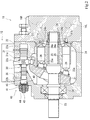
- the hydraulic pump 11 having such a function is a so-called variable displacement swash plate pump, and has a swash plate 21.
- the swash plate 21 is configured to be tiltable, and the hydraulic pump 11 changes the discharge capacity q according to the tilt angle of the swash plate 21.
- the hydraulic pump 11 includes a casing 22, a rotating shaft 23, a cylinder block 24, a plurality of pistons 25, a plurality of shoes 26, and a valve plate 27.
- the casing 22 is formed in a hollow shape, and a rotating shaft 23, a cylinder block 24, a plurality of pistons 25, a plurality of shoes 26, and a valve plate 27 are accommodated therein.
- the rotating shaft 23 which is one of the accommodated members, is generally formed in a columnar shape, and its axially intermediate portion and one end portion are forward and reverse to the casing 22 via bearing members 28 and 29. It is supported so that it can rotate in the direction. Moreover, the other end side part of the rotating shaft 23 protrudes from the casing 22, and the electric motor 13 is connected there.
- a cylinder block 24 is inserted through the proximal end side portion of the rotating shaft 23.
- the cylinder blocks 24 are coupled to the rotary shaft 23 so that their axes coincide with each other and are not relatively rotatable.
- the cylinder block 24 is formed with a plurality of cylinder chambers 24a opened at one end, and a piston 25 is inserted into each of the cylinder chambers 24a.
- the piston 25 can reciprocate in the cylinder chamber 24a. Further, the piston 25 has a convex spherical portion 25a at one end side portion thereof, and the convex spherical portion 25a protrudes from the cylinder chamber 24a.
- the convex spherical portion 25a is formed in a substantially spherical shape, and a shoe 26 is attached to the convex spherical portion 25a so as to be able to roll. The shoe 26 reciprocates in the axial direction together with the piston 25, and the bottom is pressed against one surface of the swash plate 21.
- the swash plate 21 has a rotation shaft 23 inserted through an inner hole thereof, and is inclined with respect to the lower end of the swash plate 21 so that the upper end of the swash plate 21 approaches the cylinder block 24.
- the swash plate 21 arranged in this way can tilt with respect to the rotating shaft 23, and its tilt angle can be changed.
- each shoe 26 is pressed against the swash plate 21 thus configured, and the shoe 26 rotates together with the piston 25 when the cylinder block 24 rotates.
- the shoe 26 since the shoe 26 is pressed against one surface of the swash plate 21, the shoe 26 slides and rotates about the axis on the surface of the inclined swash plate 21.
- the piston 25 reciprocates in the cylinder chamber 24a.
- a cylinder port 24b connected to each of the cylinder chambers 24a is formed at the other end of the cylinder block 24, and a valve plate 27 is provided so as to be in contact with the other end.
- the valve plate 27 is fixed to the casing 22 and is provided to be rotatable relative to the cylinder block 24.
- the valve plate 27 is formed with two ports 11a and 11b connected to the first liquid passage 16R and the second liquid passage 16L, respectively.
- the two ports 11 a and 11 b are drawn shifted in the circumferential direction.
- These two ports 11a and 11b are arranged so as to correspond to the plurality of cylinder ports 24b, and the plurality of cylinder ports 24b are connected to one of the two ports 11a and 11b when the cylinder block 24 rotates. It can be switched to either one.
- the hydraulic pump 11 configured as described above sucks hydraulic fluid from one port 11a into the cylinder chamber 24a through the cylinder port 24b.
- the sucked hydraulic fluid is pushed by the piston 25 and discharged from the other port 11b through the cylinder port 24b after the cylinder block 24 has rotated about 180 degrees.
- the hydraulic pump 11 sucks the hydraulic fluid from the other port 11b and discharges the hydraulic fluid from one port.
- the hydraulic pump 11 configured as described above can change the moving amount of the piston 25 by tilting the swash plate 21, and the discharge capacity q of the hydraulic pump 11 changes accordingly.
- the discharge capacity q of the hydraulic pump 11 changes according to the tilt angle of the swash plate 21.
- the hydraulic pump 11 thus configured is provided with a discharge capacity adjusting mechanism 12 as shown in FIG. 1 in order to change the tilt angle of the swash plate 21.
- the discharge capacity adjusting mechanism 12 is a so-called regulator, and has a function of changing the discharge capacity by changing the tilt angle of the swash plate 21 as described above.
- the servo piston 31 and the tilt angle control valve 32 are used.
- an electromagnetic proportional control valve 33 The servo piston 31 is formed in a substantially cylindrical shape, and is accommodated in the upper part of the casing 22 in FIG.
- the servo piston 31 is disposed in the casing 22 so as to be capable of reciprocating in its axial direction.
- the casing 22 has a large-diameter chamber 22a and a small-diameter chamber 22b at positions corresponding to both ends of the servo piston 31, respectively. Is formed.
- the servo piston 31 receives pressures pa and pb of the pressurized liquid guided to the large diameter chamber 22a and the small diameter chamber 22b (that is, the large diameter chamber pressure pa and the small diameter chamber pressure pb) at both ends.
- the servo piston 31 has different outer diameters at one end side portion and the other end side portion, and the areas for receiving the large-diameter chamber pressure pa and the small-diameter chamber pressure pb, that is, the pressure receiving areas are different.
- the servo piston 31 has a connecting member 31a, which will be described in detail later, in the middle portion thereof, and a compression coil spring 30 is provided on the surface of the connecting member 31a on the small-diameter chamber side.
- the compression coil spring 30 that is an urging member urges the servo piston 31 toward the large-diameter chamber 22a (that is, the right side in FIG. 2). Therefore, the servo piston 31 moves to a position where the urging force of the compression coil spring, the thrust due to the small diameter chamber pressure pb, and the thrust due to the large diameter chamber pressure pa are balanced. Note that the compression coil spring 30 is not necessarily provided.
- the servo piston 31 is connected to the upper end of the swash plate 21 by a connecting member 31a. Therefore, the swash plate 21 falls to increase the discharge capacity q when the servo piston 31 moves toward the large diameter chamber 22a, and the discharge capacity when the servo piston 31 moves toward the small diameter chamber 22b. Get up to reduce q. Further, in the hydraulic pump 11, with respect to the servo piston 31, the movement amount of the servo piston 31 toward the large-diameter chamber 22a is regulated as follows. That is, when the servo piston 31 moves toward the large-diameter chamber 22a, it hits the wall surface of the large-diameter chamber 22a that is a stopper, and cannot move further.
- the hydraulic pump 11 includes a minimum capacity adjusting mechanism 40 for physically limiting the amount of movement of the servo piston 31 toward the small diameter chamber 22b, and the other small diameter chamber 22b of the casing 22 has a minimum capacity. An opening is formed to provide the adjustment mechanism 40.
- the minimum capacity adjusting mechanism 40 includes a lid 41, a contact member 42, an adjusting screw 43, and a lock nut 44.
- the lid body 41 is generally formed in a cylindrical shape, and the tip side portion is formed with a smaller diameter than the remaining portion.
- the lid 41 has a tip end portion screwed into the opening of the small diameter chamber 22b and closes the opening of the small diameter chamber 22b.
- the inner hole of the lid body 41 is formed with a larger diameter at the distal end side than the proximal end portion, and a substantially disc-shaped contact member 42 is formed on the distal end side portion along the axis of the inner hole. It is inserted so that movement is possible along.
- An O-ring 45 is provided on the outer peripheral surface of the contact member 42, and the O-ring 45 prevents the pilot liquid from leaking out from the small diameter chamber 22 b.
- An adjustment screw 43 is screwed to the proximal end portion of the inner hole of the lid 41 to adjust the position of the contact member 42. The adjustment screw 43 is turned by rotating the adjustment screw 43. Can be adjusted.
- the servo piston 31 when the pressure liquid is guided to the large diameter chamber 22a and the servo piston 31 moves to the small diameter chamber 22b, the servo piston 31 eventually hits the contact member 42, and the servo piston The movement of 31 is physically restricted. That is, the movement amount of the servo piston 31 is limited by the contact member 42, thereby limiting the minimum tilt amount.
- the position of the contact member 42 having such a function can be changed by the adjusting screw 43 as described above. That is, by changing the position of the abutting member 42, the limited movement amount of the servo piston 31 can be adjusted. Thereby, in the hydraulic pump 11, the tilt amount can be mechanically adjusted by turning the adjusting screw 43 of the minimum capacity adjusting mechanism 40.
- the movement amount of the servo piston 31 is limited by the stopper and the minimum capacity adjustment mechanism 40, so that the swash plate 21 is within the range between the maximum tilt amount and the minimum tilt amount.
- the amount of tilt of the swash plate 21 is limited so as to move.
- the discharge capacity q of the hydraulic pump 11 is physically limited within the range between the maximum discharge capacity q max and the minimum discharge capacity q min, and the servo piston is used to change the discharge capacity q within the range between them. 31 moves.
- pressure fluid for moving the servo piston 31 is guided to the large diameter chamber 22a and the small diameter chamber 22b, and each chamber 22a, 22b is connected to the discharge pressure introduction passage 39 via the discharge pressure selection passage 35 to guide the pressure fluid.
- each chamber 22a, 22b is connected to the discharge pressure introduction passage 39 via the discharge pressure selection passage 35 to guide the pressure fluid.
- the discharge pressure introduction passage 39 is disposed so as to connect the first liquid passage 16R and the second liquid passage 16L.
- a shuttle valve 34 is interposed in the middle of the discharge pressure introduction passage 39, and the shuttle valve 34 is connected to the small-diameter chamber 22b through a discharge pressure selection passage 35.
- the shuttle valve 34 arranged in this manner selects a high-pressure hydraulic fluid from among the hydraulic fluid flowing through the first liquid passage 16R and the second liquid passage 16L, and selects the selected high-pressure hydraulic fluid as a discharge pressure. Output to the passage 35.
- a tilt angle control valve 32 and an electromagnetic proportional control valve 33 are connected to the discharge pressure selection passage 35.
- the tilt angle control valve 32 is, for example, a pilot-type spool valve, and is connected to the tank 19 and the large-diameter chamber 22a in addition to the discharge pressure selection passage 35. That is, the tilt angle control valve 32 adjusts the large-diameter chamber pressure pa output to the large-diameter chamber 22a according to the control pressure p input thereto. More specifically, the tilt angle control valve 32 moves the spool 32a according to the control pressure p, and the opening area between the discharge pressure selection passage 35 and the large diameter chamber 22a, and the tank 19 and the large diameter chamber 22a. The large-diameter chamber pressure pa is adjusted by changing the opening area.
- the tilt angle control valve 32 has a sleeve 32b, and the sleeve 32b is fitted on the spool 32a so as to be relatively movable. That is, the sleeve 32b can change the relative position with respect to the spool 32a, whereby the opening area between the discharge pressure selection passage 35 and the large diameter chamber 22a, and the opening between the tank 19 and the large diameter chamber 22a. The area can be changed.
- the sleeve 32b is connected to the servo piston 31 via a feedback lever 32c, and the sleeve 32b moves in conjunction with the servo piston 31.
- the tilt angle control valve 32 configured as described above can change the tilt angle of the swash plate 21 by moving the servo piston 31 by moving the spool 32a and adjusting the large-diameter chamber pressure pa. . Further, the sleeve 32b changes its relative position with respect to the spool 32a in conjunction with the servo piston 31, and when the servo piston 31 moves to a position where the force acting on it is balanced (that is, a position corresponding to the amount of movement of the spool 32a), the discharge pressure is increased. The space between the selection passage 35 and the tank 19 and the large-diameter chamber 22a is closed.
- the servo piston 31 can be held at a position corresponding to the control pressure p input to the tilt angle control valve 32, that is, the control pressure p input to the tilt angle control valve 32.
- the tilt angle of the swash plate 21 can be held at a corresponding angle.
- An electromagnetic proportional control valve 33 is connected to the tilt angle control valve 32 having such a function in order to input a control pressure p thereto.
- the electromagnetic proportional control valve 33 is connected to the tilt angle control valve 32 and the discharge pressure selection passage 35 as described above, and is also connected to the tank 19, and the control pressure of the pressure corresponding to the signal input thereto. p is output to the tilt angle control valve 32. Thereby, the servo piston 31 can be moved to a position corresponding to the signal input to the electromagnetic proportional control valve 33, and the swash plate 21 can be tilted to an angle corresponding to the signal. That is, the discharge capacity q can be adjusted to an amount corresponding to the signal input to the electromagnetic proportional control valve 33.
- the electric motor 13 is connected to the hydraulic pump 11 configured as described above via a speed reducer or the like so that the rotary shaft 23 can be rotationally driven.
- the electric motor 13 is a servo motor, and is configured to be able to switch the rotation direction in accordance with a signal input thereto, that is, configured to be able to rotate the rotation shaft 23 in the forward direction and the reverse direction.
- the hydraulic pump 11 can switch the direction in which the hydraulic fluid is discharged (that is, the ports 11a and 11b).
- the electric motor 13 can change the rotation speed N in accordance with a signal input thereto, that is, the rotation speed of the rotary shaft 23 can be changed.
- the flow rate of the discharged hydraulic fluid can be increased or decreased by changing the rotation speed of the rotary shaft 23.
- the hydraulic fluid discharged while the flow rate is adjusted in this way is supplied from the hydraulic pump 11 to the cylinder mechanism 2 via either the first liquid passage 16R or the second liquid passage 16L.
- relief valves 17R and 17L and check valves 18R and 18L are connected to the first fluid passage 16R and the second fluid passage 16L.
- the relief valves 17R and 17L are connected to the first liquid passage 16R and the second liquid passage 16L, respectively, and are also connected to the tank 19.
- the check valves 18R and 18L are also connected to the first liquid passage 16R and the second liquid passage 16L, respectively, and are also connected to the tank 19.
- the check valves 18R and 18L arranged in this way allow the flow of the hydraulic fluid from the tank 19 to the corresponding first liquid passage 16R and the second liquid passage 16L, but prevent the reverse flow. Accordingly, the check valves 18R and 18L suck up the hydraulic fluid from the tank 19 when the hydraulic fluid flowing through the corresponding first fluid passage 16R and the second fluid passage 16L is insufficient, and the corresponding first fluid passage 16R and the first fluid passage 16R. Replenish the two-liquid passage 16L.
- the check valve 18L is configured such that the fluid pressure in the first fluid passage 16R is guided as a pilot pressure.
- the check valve 18L causes the second liquid passage 16L and the tank 19 to communicate with each other when the pressure of the hydraulic fluid flowing through the first liquid passage 16R (ie, the pilot pressure) exceeds a predetermined set pressure.
- the control device 14 is electrically connected to the motor 13 and the electromagnetic proportional control valve 33 in order to control the movement of the motor 13 and the electromagnetic proportional control valve 33.
- the control device 14 outputs signals to the electric motor 13 and the electromagnetic proportional control valve 33 to control their operations.
- the switching unit 15 is also electrically connected to the control device 14.
- the switching unit 15 is, for example, a dial type or button type input device, and is configured to be operable to indicate one of three operation modes described later. That is, the switching unit 15 is configured to be able to select any one of three operation modes including a low noise mode, a balance mode, and a low torque mode, and sends a signal according to the selected operation mode to the control device. 14 for output.
- the low noise mode is a mode in which the electric motor 13 is driven at a first specified rotational speed N L or less that can suppress the driving sound generated from the electric motor 13.
- the low torque mode is a mode in which the electric motor 13 is driven at the second specified rotational speed NH where the driving torque of the electric motor 13 is the smallest and a rotational speed in the vicinity thereof, and the balance mode is a torque that suppresses the driving sound.
- the rotation speeds N L , N H , and NB satisfy N L ⁇ N B ⁇ N H.
- Pressure sensors 36R and 36L which are pressure detectors, are connected to the two liquid passages 16R and 16L, respectively, and detect the pressure of the working fluid flowing through the corresponding liquid passages 16R and 16L. That is, the first pressure sensor 36R detects the pressure of the hydraulic fluid flowing through the first liquid passage 16R, and the second pressure sensor 36L detects the pressure of the hydraulic fluid flowing through the second liquid passage 16L.
- the liquid temperature sensor 37 is connected to the tank 19 and detects the temperature of the hydraulic fluid in the tank 19.
- the rotational speed sensor 38 is provided in the electric motor 13 and detects the rotational speed N of the electric motor 13.
- the four sensors 36R, 36L, 37, and 38 configured in this manner output signals corresponding to the detection results to the control device 14, and the control device 14 is input from the four sensors 36R, 36L, 37, and 38.
- the movement of the electric motor 13 and the electromagnetic proportional control valve 33 is controlled based on the received signal.
- the control device 14 also determines the rotation direction and the number of rotations of the electric motor 13 and the pump tilt angle including the electromagnetic proportional control valve 33 according to the operation process of the machine, for example, the lowering of the cylinder mechanism 2, the pressure holding, and the rising. To control. Below, control in the process which hold
- control unit 14 first to lower the discharge capacity q of the hydraulic pump 11 to set the lower limit discharge capacity q L, to control the movement of the solenoid proportional control valve 33.
- the set lower limit discharge capacity q L a discharge capacity that is set according to the operation mode will be described later
- the minimum discharge displacement q min is greater than the discharge capacity described above.
- Controller 14 controls the movement of the solenoid proportional control valve 33 as the discharge capacity q of the hydraulic pump 11 is set lower discharge capacity q L to above.
- control device 14 operates the motor 13 so that the liquid passages 16R and 16L connected to the discharge-side port among the ports 11a and 11b are maintained at a holding pressure corresponding to the load received by the rod 2b of the cylinder mechanism 2.
- the control device 14 performs PID control so as to adjust the rotational speed N of the electric motor 13 so that the pressure command value from an operation device (not shown) matches the detection results of the pressure sensors 36R and 36L.
- the rotation direction of the electric motor 13 is reversed depending on the direction of the load received by the rod 2b of the cylinder mechanism 2. Thereby, the pressure of the hydraulic fluid can be held to hold the position of the rod 2b of the cylinder mechanism 2.
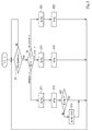
- Such function controller having a 14, as described above operating mode being adapted to vary the set lower limit discharge capacity q L in accordance with the setting procedure of setting the lower limit discharge capacity q L is below (i.e., setting processing ) Will be described with reference to the flowchart of FIG.
- step S1 which is a pressure holding determination step, one of the hydraulic fluid pressures flowing through the two liquid passages 16R and 16L is held at the holding pressure in order to hold the position of the cylinder mechanism 2, that is, a hydraulic pressure supply. It is determined whether or not the device 1 is in a pressure holding state. More specifically, the control device 14 detects the pressure of the working fluid flowing through the two liquid passages 16R and 16L based on signals from the pressure sensors 36R and 36L. Furthermore, the control device 14 determines whether one of the two detected pressures is equal to or higher than the holding pressure.
- the control device 14 performs normal rotation speed control, that is, controls the rotation direction and rotation speed of the electric motor 13 and the tilt angle of the hydraulic pump 11 to lower or raise the cylinder mechanism 2. To do. The control device 14 repeatedly determines whether or not the pressure is maintained while performing such normal rotation speed control. When it is determined that the pressure is maintained, the process proceeds to step S2.
- step S2 which is a selection mode determination step, the control device 14 determines which of the three operation modes is selected. More specifically, when a signal related to the operation mode is output from the switching unit 15, the control device 14 stores the operation mode selected based on the signal to be overwritten, and the stored operation mode. The currently selected operation mode is determined based on. When the selected mode is the low noise mode, the process proceeds to step S11.
- step S11 which is the lower limit setting step
- the control unit 14 sets the setting lower discharge capacity q L to the first predetermined volume q 1.
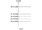
- the first predetermined capacity q 1 is set to be larger than the aforementioned minimum discharge capacity q min (see the solid line and the alternate long and short dash line in FIG. 4).
- step S12 which is a discharge capacity setting step
- the control device 14 controls the operation of the electromagnetic proportional control valve 33 to reduce the discharge capacity q of the hydraulic pump 11 in order to suppress the flow rate of the hydraulic fluid discharged from the hydraulic pump 11.
- the lower limit discharge capacity q L that is, the first predetermined capacity q 1 is set.
- the minimum discharge flow rate necessary in the pressure holding state can be estimated in advance from the amount of leakage.
- the discharge flow rate of the hydraulic pump 11 is proportional to the discharge capacity q and the rotational speed N of the electric motor 13. Therefore, the first predetermined capacity q 1 is set to a value based on the minimum discharge flow rate so that the electric motor 13 can mainly operate at the first specified rotational speed NL or less where the driving sound of the electric motor 13 is small. the noise mode, the discharge capacity q of the hydraulic pump 11 is maintained at essentially the first predetermined volume q 1.
- the control unit 14 after setting, while maintaining the discharge capacity q to a first predetermined capacity q 1, the pressure detected to control the operation of the electric motor 13 so as to be maintained at or above the holding pressure.
- the control device 14 increases the pump capacity and discharges the hydraulic pump 11 when the detected pressure becomes less than the holding pressure due to a large internal leak of the hydraulic pump 11 due to a change in the temperature of the hydraulic fluid. Increase the flow rate. In this way, the hydraulic pressure supply device 1 maintains the pressure holding state.
- the discharge capacity q of the hydraulic pump 11 reaches the first predetermined capacity q 1, the process proceeds to step S13.
- step S13 which is a rotational speed determination step, the control device 14 determines whether or not the rotational speed N of the electric motor 13 is equal to or less than the first specified rotational speed NL .
- the first specified rotation speed N L is set to a rotation speed at which the generated drive sound is less than the allowable volume or the drive sound frequency is less than the assumed frequency, and thereby the drive generated by the motor 13 as described above. The sound can be suppressed.
- the first specified rotational speed N L is set at, for example, 10% to 80% with respect to the maximum rotational speed. That is, the control device 14 determines whether or not the driving sound generated by the electric motor 13 is loud.
- step S1 determines whether the rotational speed N of the electric motor 13 is equal to or less than the first specified rotational speed NL . If it is determined that the rotational speed N of the electric motor 13 is equal to or less than the first specified rotational speed NL , the process returns to step S1 to determine again whether the pressure is maintained. On the other hand, if it is determined that the rotation speed is equal to or higher than the first specified rotation speed N L , the process proceeds to step S14.
- step S14 which is the lower limit changing step
- setting a lower limit discharge capacity q L is changed by the controller 14. That is, the control device 14 increases the discharge capacity q so as to decrease the rotational speed N of the electric motor 13.
- the discharge flow rate of the hydraulic pump 11 is proportional to the rotational speed N of the electric motor 13 ⁇ the discharge capacity q, and the rotational speed N of the electric motor 13 can be lowered by increasing the discharge capacity q. Therefore, the control device 14 increases the discharge capacity q and decreases the rotational speed N of the electric motor 13.
- the control unit 14 adds a predetermined increment ⁇ q to set the value was as set lower discharge capacity q L, the value is set as a new set lower discharge capacity q L.
- the control unit 14 controls the movement of the solenoid proportional control valve 33 so as to change the discharge capacity q with a preference lower discharge capacity q L is set.
- the discharge capacity q is changed in this way, the rotational speed N of the electric motor 13 can be reduced, and the driving sound generated by the electric motor 13 can be reduced. That is, noise generated by the electric motor 13 can be suppressed.
- the process returns to step S1, it is determined whether re-pressure holding state.
- step S2 the operation mode selected in step S2 is the low torque mode
- step S21 which is the lower limit setting step
- the control unit 14 sets the setting lower discharge capacity q L to the second predetermined capacity q 2.
- the second predetermined capacity q 2 is set first smaller than the predetermined capacity q 1 (see dashed line 4 the solid lines and two-dot).
- step S22 which is a discharge capacity setting step
- the control device 14 controls the operation of the electromagnetic proportional control valve 33 to reduce the discharge capacity q of the hydraulic pump 11 in order to suppress the flow rate of the hydraulic fluid discharged from the hydraulic pump 11.
- the lower limit discharge capacity q L that is, the second predetermined capacity q 2 is set.
- the control unit 14, after setting, while maintaining the discharge capacity q to the second predetermined capacity q 2, the pressure detected to control the operation of the electric motor 13 so as to be maintained at or above the holding pressure.
- the low torque mode is a mode in which the electric motor 13 is operated at and near the second specified rotational speed NH where the driving torque of the electric motor 13 is the smallest.
- the second predetermined capacity q 2 is capable of operating the motor 13 at the second specified rotational speed NH with the smallest driving torque of the electric motor 13 and the rotational speed in the vicinity thereof based on the aforementioned minimum discharge flow rate. It is set to such a value that, in the low torque mode discharge capacity q of the hydraulic pump 11 is maintained at a second predetermined capacity q 2. Thus, in the hydraulic pressure supply device 1, the pressure holding state is maintained while the electric motor 13 maintains the low torque in the low torque mode. On setting process, when the discharge capacity q of the hydraulic pump 11 is a second predetermined capacity q 2, the process returns to step S1, it is determined whether re-pressure holding state.
- step S2 When the operation mode is balance mode.
- step S31 which is the lower limit setting step, the control unit 14 sets the setting lower discharge capacity q L to a third predetermined capacity q 3.
- third predetermined capacity q 3 is and less than the first predetermined volume q 1 is set larger than the second predetermined capacity q 2 (see dashed line 4 the solid lines and three points).
- step S32 When setting the lower limit discharge capacity q L is set to the third predetermined capacity q 3, the process proceeds to step S32.
- step S32 which is a discharge capacity setting step
- the control device 14 controls the operation of the electromagnetic proportional control valve 33 to reduce the discharge capacity q of the hydraulic pump 11 in order to suppress the flow rate of the hydraulic fluid discharged from the hydraulic pump 11.
- the lower limit discharge capacity q L that is, the third predetermined capacity q 3 is set.
- the control unit 14, after setting, while maintaining the discharge capacity q in the third predetermined capacity q 3, the pressure detected to control the operation of the electric motor 13 so as to be maintained at or above the holding pressure.
- In balance mode while suppressing the driving noise from the low torque mode is a mode for driving the electric motor 13 in the third operating speed N B and its vicinity can be driven from the low noise mode at low torque.
- a third predetermined capacity q 3 is the smallest based on the discharge flow rate, defined by the rotational speed N B and the rotational speed of the near and the electric motor 13 is set to such a value as can operate, in balance mode , the discharge capacity q of the hydraulic pump 11 is maintained at a third predetermined capacity q 3.
- the process returns to step S1, it is determined whether re-pressure holding state.
- the discharge capacity q is minimum discharge capacity q min larger than the set by setting the lower limit discharge capacity q L set lower discharge capacity of the hydraulic pump 11 in the pressure holding state q L It is possible to fluctuate.
- the rotational speed N of the electric motor 13 may be excessively larger than a desired value depending on the driving state of the hydraulic pressure supply device 1 in order to maintain the pressure.
- the discharge capacity q can be changed in accordance with the driving status of the hydraulic pressure supply device 1, for example, the rotational speed N of the electric motor 13, the temperature of the hydraulic fluid, etc. even in the pressure holding state. Therefore, it is possible to suppress a large fluctuation in the rotational speed N of the electric motor 13 so as to maintain the hydraulic pressure of the hydraulic fluid in the pressure holding state.
- the hydraulic pressure supply device 1 can reduce the noise of the electric motor 13 in the low noise mode, and can use the electric motor 13 having a small output in the low torque mode. Further, in the balance mode, the motor 13 can be driven with a low torque, that is, a small current, with respect to the low noise mode while reducing the noise of the motor, and heat generation from the motor 13 can be suppressed. Moreover, in the hydraulic pressure supply apparatus 1, since these three modes can be switched according to a user's preference and an environmental condition by the switching part 15, the convenience as an industrial machine provided with the hydraulic pressure supply apparatus 1 is high.
- the apparatus when working with industrial machines at night, etc., the noise of the motor 13 is reduced in the low noise mode in consideration of noise, and when working in an environment with relatively large background noise in the daytime, etc.
- the apparatus In the low torque mode, the apparatus can be driven while suppressing heat generation from the electric motor 13. Moreover, even if it is daytime, when a loud sound is not emitted environmentally, the heat generation from the electric motor 13 can be suppressed while reducing the driving sound in the electric motor 13 in the balance mode.
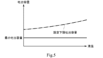
- the control unit 14 of the hydraulic supply device 1 changes the setting lower discharge capacity q L based on the liquid temperature. That is, when the liquid temperature rises, the viscosity decreases, and the amount of leakage from the high pressure portion in the hydraulic pressure supply device 1 increases. Therefore, when the set lower limit discharge capacity q L a constant value, it is necessary to increase the rotational speed N of the electric motor 13 in order to suppress the pressure drop of the hydraulic fluid.
- the control device 14 changes the set lower limit discharge capacity q L in accordance with the liquid temperature, as shown in FIG. That is, setting a lower limit discharge capacity q L is set essentially larger than the minimum discharge capacity q min, increases in response to the liquid temperature rise.
- Setting the lower limit discharge capacity q L may be set to the minimum discharge capacity q min is not smaller than the value.
- the pressure supply device 1 instead of mechanically changing the set lower limit discharge capacity q L by minimum capacity adjusting mechanism 40 can be electrically varied. Therefore, as compared with the case where mechanically change the setting lower discharge capacity q L, can be changed easily set lower discharge capacity q L, also enhance the repeatability of the value of the setting lower discharge capacity q L in each mode be able to.
- setting a lower limit discharge capacity q L is set based on both the operation mode and the liquid temperature is not always necessary to change based both on. That is, setting a lower limit discharge capacity q L may be set based only on the operation mode and the liquid may be set based only on the temperature.
- the three predetermined volumes q 1 , q 2 , and q 3 set as the set lower limit discharge capacity q L vary depending on the model of the hydraulic pump 11 (that is, the discharge capacity q) and the configuration of the hydraulic pressure supply device 1. As described above, it can be set based on the leak amount in the hydraulic pressure supply device 1.
- the hydraulic pressure supply device 1 of the present embodiment is configured so that one mode can be selected from the three operation modes, but the selectable operation modes are not limited to three.
- two selectable operation modes may be a low noise mode and a low torque mode.
- four or more operation modes may be selected by adding another mode.
- the hydraulic pressure supply apparatus 1 of this embodiment although the swash plate pump is used as the hydraulic pressure pump 11, it is not limited to this.
- an oblique pump may be used as long as the discharge capacity q can be changed.
- the discharge capacity adjusting mechanism 12 for tilting the swash plate 21 is not necessarily configured as described above.
- the servo piston 31 is of a pilot pressure type, but may be of an electric type that is directly driven by a servo motor or solenoid, and the configuration is not limited.
- the hydraulic pump 11 is a double-rotating pump, but may be a single-rotating pump that rotates only in one direction.
- a direction switching valve is interposed between the pump and the actuator, and the direction in which the hydraulic oil flows is switched by the direction switching valve.
- a servo motor is employed as the electric motor 13, but the electric motor 13 is not necessarily limited to the servo motor, and any electric motor capable of controlling the rotational speed may be used.
- the cylinder mechanism 2 is disclosed as an example of the actuator, but the actuator is not limited to the cylinder mechanism 2.
- a single-acting piston and a hydraulic motor as described above may be used as long as the actuator can be driven by supplying hydraulic fluid.
- the applied machine is not limited to an industrial machine, and can be applied to all robots.
Landscapes
- Engineering & Computer Science (AREA)
- Physics & Mathematics (AREA)
- Fluid Mechanics (AREA)
- Mechanical Engineering (AREA)
- General Engineering & Computer Science (AREA)
- Chemical & Material Sciences (AREA)
- Analytical Chemistry (AREA)
- Control Of Positive-Displacement Pumps (AREA)
- Fluid-Pressure Circuits (AREA)
Abstract
液圧供給装置は、吐出容量を変更可能な液圧ポンプと、回転数を変更することができる電動機と、最大吐出容量と最小吐出容量との間の範囲において液圧ポンプの吐出容量を調整可能な吐出容量調整機構と、液圧ポンプから吐出される作動液の圧力を検出する圧力検出器と、電動機の回転数を検出する回転数検出器と、回転数検出器で検出される回転数に基づいて電動機及び吐出容量調整機構の動作を制御してアクチュエータを任意の圧力にて保持する制御装置とを備え、制御装置は、アクチュエータの圧力を保持する際、液圧ポンプの吐出容量が設定下限吐出容量となるように吐出容量調整機構の動作を制御し、設定下限吐出容量は、最小吐出容量より大きく、且つ前記制御装置によって調整可能に設定されている。
Description
本発明は、アクチュエータに液圧を供給して駆動させる液圧供給装置に関する。
液圧ポンプからアクチュエータに液圧を供給して駆動する液圧供給装置が知られている。液圧供給装置において、液圧ポンプはサーボモータ等のような回転数制御が可能な電動機によって回転駆動されており、回転数制御によってその吐出流量を調整してアクチュエータの速度、位置、及び荷重を制御することができるようになっている。また、液圧供給装置では、液圧ポンプの吐出容量が変更可能に構成され、このような液圧供給装置としては、例えば特許文献1及び2のような駆動システムが知られている。
特許文献1の駆動システムでは、吐出圧の大きさによって制御を変えるようになっており、吐出圧が予め定められたカットオフ開始圧力未満においては電動機の回転数を調整することによってポンプの吐出流量が制御される。他方、吐出圧が予め定められるカットオフ開始圧力に達すると、電動機の回転数を一定に維持し、ポンプ吐出容量を調整することによってポンプの吐出流量が制御される。
また、特許文献2の駆動システムでは、ポンプ容量が2段階で切換え可能に構成されており、それほど大きな流量を必要としない保圧工程においてポンプの容量が小さい方に設定される。他方、制御装置は、ポンプのトルクを一定の値に確保すべくサーボモータの回転数を制御するようになっている。
特許文献1及び2の駆動システムでは、共にアクチュエータに供給する作動液の圧力を維持することを目的とする場合、それほど多くの量の作動液を供給する必要がない。それ故、特許文献1の駆動システムでは、ポンプが圧力調整(カットオフ)機構を備えており、圧力調整機構によってポンプの容量が機械的に調整される。例えば、保圧工程では、圧力調整機構によってポンプの容量がカットオフ圧力を保持可能な容量に調整される。しかし、カットオフ圧力が最初に調整された圧力で固定されてしまうので、機械の負荷(プレスにおける製品の板厚・材料の相違、樹脂・粉末成型における材料の相違等)に応じて圧力を調整することができない。
他方、特許文献2の駆動システムでは、ポンプの吐出容量が最小吐出容量に設定されている。この最小吐出容量は、一般的に斜板の傾転が所定の角度より小さくならないように機械的に制限することによって達成されており、斜板の傾転の制限は主に機械的なストッパ等で行われている。それ故、最小吐出容量を変更する場合、それに応じてポンプの設計を変える必要がある。即ち、同じサイズのポンプであっても、最小吐出容量が異なるだけで異なる部品を用いる必要があり、部品を大量生産することができず、ポンプの製造コストが増加する。それ故、ポンプの最小吐出容量は、同じサイズのポンプに対して使用態様に依らず同じ容量に設定されている。あるいは、ポンプにおいてねじ等によって最小吐出容量を調整可能なものもある。しかし、この場合は、ワークの種類を変える、いわゆる段取り替えの度に調整ねじを調整し直すことが必要となるので作業性が悪い。
ここで、2つの駆動システムにおける圧力保持時の内部リーク量(ポンプ内部で発生するリーク量)に着目する。各駆動システムにおける内部リーク量は、それを構成する機器、並びに作動液の温度及び圧力等の駆動システムの駆動状態に応じて変化する。前述の通り、ポンプでは、使用態様及び駆動状態に関わらず最小吐出容量がある値に設定されている。それ故、どのような使用態様及び駆動状態においても内部リークによって不足する作動液の流量を補うことができるようにするために、最小吐出容量は、想定される内部リークのうち最も多い流量よりも更に大きめに設定される。そうすると、圧力保持状態において、ポンプ吐出圧とポンプ吐出容量との積で定まるポンプ駆動トルクが大きくなるので、大型(大出力)の電動機が必要となる。
そこで、電動機の大型化を抑えるべく最小吐出容量を、前述するような容量よりも小さめに設定することが考えられる。この場合、ポンプの吐出流量はポンプ吐出容量とポンプ回転数との積で定まることから、前述する場合よりも電動機の回転数を上げることによって内部リーク量に相当する作動液の流量を補うことができる。しかしながら、連続運転等で作動液が高温になった場合、あるいは、夏季等において雰囲気温度が高温である場合に以下のような事態が顕著となる。即ち、作動液が高温になることで駆動システムにおける内部リーク量が増加し、更に多くの作動液をポンプから吐出させる必要が生じる。そうすると、想定する回転数より高い回転数にて電動機を駆動する必要があり、その際に電動機から発せられる駆動音が大きくなり、回転数の増加に伴い発生する駆動音の周波数も変わって耳触りとなり騒音となる。即ち、ポンプの使用態様に応じて電動機の回転数が変化し、騒音を発生させることになる。
そこで本発明は、アクチュエータの圧力を保持する圧力保持状態において、電動機の回転数の変動を抑制できる液圧供給装置を提供することを目的としている。
本発明の液圧供給装置は、受ける荷重に応じた保持圧力の作動液をアクチュエータに供給するものであって、吐出容量を変更可能であって、該吐出容量と駆動される回転数に応じた流量の作動液を吐出する液圧ポンプと、前記液圧ポンプを回転駆動可能に構成され、且つその回転数を変更することができる電動機と、所定の最大吐出容量と所定の最小吐出容量との間の範囲において前記液圧ポンプの吐出容量を調整可能な吐出容量調整機構と、前記液圧ポンプから吐出される作動液の圧力を検出する圧力検出器と、前記電動機の回転数を検出する回転数検出器と、前記圧力検出器で検出される圧力が保持圧力にて維持されるように、前記回転数検出器で検出される回転数に基づいて前記電動機及び前記吐出容量調整機構の動作を制御する制御装置とを備え、前記制御装置は、前記アクチュエータに供給される作動液の圧力を前記保持圧力にて保持する際、前記液圧ポンプの吐出容量が設定下限吐出容量となるように前記吐出容量調整機構の動作を制御し、前記設定下限吐出容量は、前記最小吐出容量より大きく、且つ前記制御装置によって変動可能に設定されているものである。
本発明に従えば、アクチュエータの圧力を保持する圧力保持状態における液圧ポンプの吐出容量を最小吐出容量より大きい設定下限吐出容量に設定して、設定下限吐出容量を調整することを可能にしている。即ち、用いられる機械装置が異なっても圧力保持状態においても液圧供給装置の駆動状況、例えば電動機の回転数及び作動液の温度等に応じて設定下限吐出容量を調整することができるので、圧力保持状態において作動液の液圧を維持すべく電動機の回転数が上昇することを抑制することができる。
上記発明において、前記制御装置は、前記回転数検出器で検出される回転数に応じて前記設定下限吐出容量を調整してもよい。
上記構成に従えば、電動機の回転数を所望の回転数及びその付近にて維持することができる。
上記発明において、前記制御装置は、前記アクチュエータの圧力を保持する際、前記回転数検出器で検出される前記電動機の回転数が予め定められる第1規定回転数以下の場合において前記設定下限吐出容量を第1所定容量に設定し、前記回転数検出器で検出される前記電動機の回転数が前記第1規定回転数を超える場合において前記電動機の回転数を前記第1規定回転数以下にすべく前記設定下限吐出容量を前記第1所定容量より増加させるように前記吐出容量調整機構の動きを制御する第1運転モードを実行してもよい。
上記構成に従えば、電動機の回転数を第1規定回転数以下に抑えることができる。このように電動機の回転数を第1規定回転数以下に抑えることによって以下のようなことを実現することができる。即ち、電動機から発せられる駆動音を第1規定回転数にて回転させた電動機で発生する駆動音以下に抑えることができ、更に駆動音周波数が高くなって耳障りとなることを抑えることができる。それ故、発せられる駆動音が許容できる音量以下、又は駆動音周波数の高さが想定した周波数以下となる回転数に第1規定回転数を設定することで、液圧供給装置による騒音を低減することができる。
上記発明において、前記アクチュエータの圧力を保持する際において運転モードを切替える切替部を有し、前記制御装置は、前記切替部に対する操作に応じて前記第1運転モードと第2運転モードとを切替えるようになっており、前記第2運転モードでは、前記圧力検出器で検出される圧力を前記保持圧力にて維持すべく、前記設定下限吐出容量を前記第1所定容量より小さい第2所定容量に設定してもよい。
上記構成に従えば、第2運転モードでは、アクチュエータの圧力を保持すべく第1運転モードより低い駆動トルクで電動機を回転させることができる。このように第1運転モードより低い駆動トルクで電動機を回転させることができるので、第1運転モードのときより小さい電流で電動機を回転させることができる。また、2つの運転モードを切替部に対する操作によって切替えることができるので、モード切替えが容易である。
上記発明において、前記制御装置は、前記切替部に対する操作に応じて第3運転モードに切替え可能であって、前記第3運転モードでは、前記圧力検出器で検出される圧力が前記保持圧力にて維持すべく、前記設定下限吐出容量を前記第2所定容量より大きくかつ第1所定容量より小さい第3所定容量としてもよい。
上記構成に従えば、第3運転モードでは、アクチュエータの圧力を保持すべく第1運転モードより高く且つ第2運転モードより低い回転数にて電動機を回転させることができる。それ故、第2運転モードより駆動音を抑えつつ、第1運転モードより小さい電流で電動機を駆動させることができる。即ち、第2運転モードより騒音の発生を抑え、第1運転モードより小さい電流で電動機を駆動することができる。
上記発明において、作動液の温度を検出する液温検出器を更に備え、前記制御装置は、前記液温検出器によって検出される液温に応じて前記設定下限吐出容量の値を調整してもよい。
上記構成に従えば、液温上昇が生じても作動液の圧力を保持圧力に維持することができ、圧力を保持すべく電動機の回転数が増加して電動機の駆動音が大きくなることを抑制することができる。
本発明によれば、アクチュエータの圧力を保持する圧力保持状態において電動機の回転数の変化を抑制できる。
以下、本発明に係る実施形態の液圧供給装置1について図面を参照して説明する。なお、以下の説明で用いる方向の概念は、説明する上で便宜上使用するものであって、発明の構成の向き等をその方向に限定するものではない。また、以下に説明する液圧供給装置1は、本発明の一実施形態に過ぎない。従って、本発明は実施形態に限定されず、発明の趣旨を逸脱しない範囲で追加、削除、変更が可能である。
産業機械及びロボットは、シリンダ機構及び液圧モータ等の種々のアクチュエータを備えており、アクチュエータを動かすことによって様々な作業を行うことができる。例えば、産業機械やロボット等には、図1に示すように、アクチュエータの一例である複動式シリンダ機構2が備わっており、このシリンダ機構2には、液圧供給装置1が接続されている。液圧供給装置1は、シリンダ機構2に作動液(油又は水等)を供給してシリンダ機構2を作動させるようになっている。以下では、液圧供給装置1について更に詳細に説明する。
[液圧供給装置1]
液圧供給装置1は、前述の通りシリンダ機構2に作動液を供給してシリンダ機構2を作動させ、また供給する作動液の流れる方向や流量等を調整することによってシリンダ機構2の動作を制御する。このような機能を有する液圧供給装置1は、主に液圧ポンプ11と、吐出容量調整機構12と、電動機13と、制御装置14と、切替部15とを備えている。液圧ポンプ11は、両回転型のポンプであり、その回転方向に応じた方向へと作動液を吐出する。更に詳細に説明すると、液圧ポンプ11は、2つのポート11a,11bを有し、正方向に回転すると一方のポート11aから作動液を吸入し、その作動液を他方のポート11bから吐出する。また、逆方向に回転すると、液圧ポンプ11は、他方のポート11bから作動液を吸入し、その作動液を一方のポート11aから吐出する。このように作動液が吸引及び吐出される2つのポート11a,11bには、第1液通路16R及び第2液通路16Lを介してシリンダ機構2が接続されており、液圧ポンプ11は、シリンダ機構2と共に閉回路を構成している。
液圧供給装置1は、前述の通りシリンダ機構2に作動液を供給してシリンダ機構2を作動させ、また供給する作動液の流れる方向や流量等を調整することによってシリンダ機構2の動作を制御する。このような機能を有する液圧供給装置1は、主に液圧ポンプ11と、吐出容量調整機構12と、電動機13と、制御装置14と、切替部15とを備えている。液圧ポンプ11は、両回転型のポンプであり、その回転方向に応じた方向へと作動液を吐出する。更に詳細に説明すると、液圧ポンプ11は、2つのポート11a,11bを有し、正方向に回転すると一方のポート11aから作動液を吸入し、その作動液を他方のポート11bから吐出する。また、逆方向に回転すると、液圧ポンプ11は、他方のポート11bから作動液を吸入し、その作動液を一方のポート11aから吐出する。このように作動液が吸引及び吐出される2つのポート11a,11bには、第1液通路16R及び第2液通路16Lを介してシリンダ機構2が接続されており、液圧ポンプ11は、シリンダ機構2と共に閉回路を構成している。
シリンダ機構2は、複動型のものであり、シリンダ2a及びロッド2bを有している。シリンダ2aには、ロッド2bが往復運動可能に挿入されている。また、シリンダ2aには、ヘッド側ポート2c及びロッド側ポート2dが形成されており、各々はヘッド側空間及びロッド側空間と繋がっている。また、ヘッド側ポート2cには、第2液通路16Lが接続され、ロッド側ポート2dには、第1液通路16Rが接続されている。このように構成されている液圧シリンダ機構2は、液圧ポンプ11から第1液通路16Rを介してロッド側ポート2dに作動液が供給されるとロッド2bがシリンダ2aに対して縮退し、また液圧ポンプ11から第2液通路16Lを介してヘッド側ポート2cに作動液が供給されるとロッド2bがシリンダ2aに対して伸長する。このようにシリンダ機構2は、液圧ポンプ11からの作動液によって作動し、また作動液の流れる方向に応じた作動方向に作動する(即ち、伸長及び縮退する)。
このような機能を有する液圧ポンプ11は、いわゆる可変容量形の斜板ポンプであり、斜板21を有している。斜板21は、傾転可能に構成されており、液圧ポンプ11は、斜板21の傾転角に応じて吐出容量qを変更する。以下では、液圧ポンプ11の構成について、その一例を図2を参照しながら更に詳細に説明する。液圧ポンプ11は、斜板21の他に、ケーシング22、回転軸23、シリンダブロック24、複数のピストン25、複数のシュー26、及びバルブプレート27を備えている。ケーシング22は、その中が中空に形成されており、その中に回転軸23、シリンダブロック24、複数のピストン25、複数のシュー26、及びバルブプレート27が収容されている。
収容されている部材のうちの1つである回転軸23は、大略円柱状に形成されており、その軸線方向中間部分及び一端部が軸受部材28,29を介してケーシング22に正方向及び逆方向に回転可能に支持されている。また、回転軸23は、その他端側部分がケーシング22から突き出ており、そこには電動機13が連結されている。また、回転軸23の基端側部分には、シリンダブロック24が挿通されている。シリンダブロック24は、互いに軸線が一致し且つ相対回転不能に回転軸23に結合されている。また、シリンダブロック24には、その一端にて開口する複数のシリンダ室24aが形成されており、シリンダ室24aの各々には、ピストン25が挿入されている。
ピストン25は、シリンダ室24a内を往復運動できるようになっている。また、ピストン25は、その一端側部分に凸球部25aを有しており、凸球部25aがシリンダ室24aから突出している。凸球部25aは、大略球状に形成されており、そこにはシュー26が転動可能に取り付けられている。シュー26は、ピストン25と共に軸線方向に往復運動し、底部が斜板21の一表面に押し付けられている。斜板21は、その内孔に回転軸23が挿通されており、その下端部に対して上端部をシリンダブロック24に近づけるようにして傾斜させて配置されている。このように配置されている斜板21は、回転軸23に対して傾転できるようになっており、その傾転角を変えることができる。
このように構成されている斜板21には、前述の通り、各シュー26が押し付けられており、シュー26は、シリンダブロック24が回転するとピストン25と一緒に回転する。その際、シュー26は、斜板21の一表面に押し付けられているので、傾転する斜板21の一表面上をその軸線回りに摺動回転する。そうすることで、ピストン25がシリンダ室24aを往復運動する。また、シリンダブロック24の他端には、シリンダ室24aの各々に繋がるシリンダポート24bが形成され、また他端に当接させるようにバルブプレート27が設けられている。バルブプレート27は、ケーシング22に固定されており、シリンダブロック24に対して相対回転可能に設けられている。また、バルブプレート27には、第1液通路16R及び第2液通路16Lに夫々繋がる2つのポート11a,11bが形成されている。なお、図2では、説明の便宜上、2つのポート11a,11bは、周方向にずらして描かれている。これら2つのポート11a,11bは、複数のシリンダポート24bに対応させて配置され、複数のシリンダポート24bは、シリンダブロック24が回転することによって接続されるポートが2つのポート11a,11bのうちの何れかへと切替わるようになっている。
このように構成される液圧ポンプ11は、例えば回転軸23が正回転すると、一方のポート11aからシリンダポート24bを介してシリンダ室24aに作動液を吸入する。また、吸入された作動液は、前記シリンダブロック24が約180度回転した後、ピストン25に押されてシリンダポート24bを介して他方のポート11bから排出される。他方、回転軸23が逆回転すると、液圧ポンプ11は、他方のポート11bから作動液を吸引し、一方のポートから作動液を排出する。このように構成されている液圧ポンプ11は、斜板21を傾転させることでピストン25の移動量を変えることができ、それに伴って液圧ポンプ11の吐出容量qが変わる。また、その移動量は斜板21の傾転角に応じて変化するので、斜板21の傾転角に応じて液圧ポンプ11の吐出容量qが変わる。このように構成されている液圧ポンプ11には、斜板21の傾転角を変えるべく図1に示すような吐出容量調整機構12が設けられている。
吐出容量調整機構12は、いわゆるレギュレータであり、前述の通り斜板21の傾転角を変えて吐出容量を変更する機能を有しており、主にサーボピストン31と、傾転角制御弁32と、電磁比例制御弁33と、を有している。サーボピストン31は、大略円柱状に形成されており、図2においてケーシング22の紙面上部に収容されている。また、サーボピストン31は、ケーシング22内においてその軸線方向に往復運動可能に配置されており、ケーシング22には、サーボピストン31の両端部に対応する位置に夫々大径室22a,小径室22bが形成されている。サーボピストン31は、大径室22a,小径室22bに導かれる圧液の圧力pa,pb(即ち、大径室圧pa及び小径室圧pb)を両端部にて夫々受圧している。また、サーボピストン31は、その一端側部分と他端側部分とが外径が異なっており、大径室圧pa,小径室圧pbを受圧する面積、即ち受圧面積が異なっている。更に、サーボピストン31は、その中間部分に後で詳述する連結部材31aを有しており、この連結部材31aの小径室側の面に圧縮コイルばね30が設けられている。付勢部材である圧縮コイルばね30は、サーボピストン31を大径室22a側(即ち、図2の紙面右側)へと付勢している。それ故、サーボピストン31は、圧縮コイルばねの付勢力と小径室圧pbによる推力と,大径室圧paによる推力とが釣り合う位置に移動する。なお、圧縮コイルばね30は、必ずしも備えていなくても良い。
また、サーボピストン31は、連結部材31aによって斜板21の上端部に連結されている。それ故、斜板21は、サーボピストン31が大径室22a側の方へと移動すると吐出容量qを増加させるように倒れ、サーボピストン31がその小径室22b側の方へと移動すると吐出容量qを減少させるように起き上がる。また、液圧ポンプ11では、サーボピストン31に関して、サーボピストン31の大径室22a側への移動量が以下のようにして規制されている。即ち、サーボピストン31は、その大径室22a側に移動すると、ストッパである大径室22aの壁面に当たり、それ以上の移動ができないようになっている。即ち、サーボピストン31の大径室22a側への移動量が大径室22aの壁面によって制限され、それによって最大傾転量が制限される。また、液圧ポンプ11は、サーボピストン31の小径室22b側への移動量を物理的に制限すべく最小容量調整機構40を備えており、ケーシング22の他方の小径室22bには、最小容量調整機構40を設けるべく開口が形成されている。
最小容量調整機構40は、蓋体41と、当接部材42と、調整ねじ43と、ロックナット44とを有している。蓋体41は、大略円筒状に形成されており、先端側部分が残余の部分より小径に形成されている。蓋体41は、その先端側部分を小径室22bの開口に螺合させ、小径室22bの開口を塞いでいる。また、蓋体41の内孔は、基端側部分に対して先端側部分が大径に形成されており、先端側部分には大略円板状の当接部材42が、内孔の軸線に沿って移動可能に嵌挿されている。当接部材42の外周面には、Oリング45が設けられており、Oリング45によって小径室22bから外側へとパイロット液が漏れ出ることを防いでいる。また、蓋体41の内孔の基端側部分には、当接部材42の位置を調整すべく調整ねじ43が螺合されており、調整ねじ43は、それを回すことによって当接部材42の位置を調整することができる。
このように構成されている最小容量調整機構40では、大径室22aに圧液が導かれてサーボピストン31が小径室22b側に移動すると、やがてサーボピストン31が当接部材42に当たり、サーボピストン31の移動が物理的に規制される。即ち、サーボピストン31の移動量を当接部材42によって制限し、それによって最小傾転量を制限している。このような機能を有する当接部材42は、前述の通り調整ねじ43によってその位置を変えることができる。即ち、その当接部材42の位置を変えることによって、サーボピストン31の制限される移動量を調整することができる。これにより、液圧ポンプ11では、最小容量調整機構40の調整ねじ43を回すことによって傾転量を機械的に調整することができる。
このように液圧ポンプ11では、ストッパ及び最小容量調整機構40によってサーボピストン31の移動量を制限することによって、斜板21が最大傾転量と最小傾転量との間の範囲内にて動くように斜板21の傾転量を制限されている。これにより、液圧ポンプ11の吐出容量qが最大吐出容量qmaxと最小吐出容量qminとの範囲内で物理的に制限され、それらの間の範囲内にて吐出容量qを変えるべくサーボピストン31が移動する。他方、大径室22a,小径室22bには、サーボピストン31を移動させる圧液が導かれ、各室22a,22bは、圧液を導くべく吐出圧選択通路35を介して吐出圧導入通路39に夫々繋がっている。
吐出圧導入通路39は、第1液通路16Rと第2液通路16Lとを繋ぐようにして配置されている。吐出圧導入通路39の途中には、シャトル弁34が介在し、またシャトル弁34は、吐出圧選択通路35を介して小径室22bに接続されている。このように配置されているシャトル弁34は、第1液通路16R及び第2液通路16Lを夫々流れる作動液のうち高圧の作動液を選択して、選択された高圧の作動液を吐出圧選択通路35に出力する。また、吐出圧選択通路35には、傾転角制御弁32と、電磁比例制御弁33が接続されている。
傾転角制御弁32は、例えばパイロット式のスプール弁であり、吐出圧選択通路35の他に、タンク19及び大径室22aに接続されている。即ち、傾転角制御弁32は、そこに入力される制御圧pに応じて大径室22aに出力する大径室圧paを調整する。更に詳細に説明すると、傾転角制御弁32は、制御圧pに応じてスプール32aを動かして吐出圧選択通路35と大径室22aとの間の開口面積、及びタンク19と大径室22aとの間の開口面積を変えて大径室圧paを調整する。
また、傾転角制御弁32は、スリーブ32bを有しており、スリーブ32bは、相対移動可能にスプール32aに外嵌されている。即ち、スリーブ32bは、スプール32aに対する相対位置を変化させることができ、それによって吐出圧選択通路35と大径室22aとの間の開口面積、及びタンク19と大径室22aとの間の開口面積を変化させることができる。また、スリーブ32bは、フィードバックレバー32cを介してサーボピストン31に連結されており、スリーブ32bは、サーボピストン31に連動して移動する。
このように構成されている傾転角制御弁32は、スプール32aを移動させて大径室圧paを調整することによってサーボピストン31を移動させて斜板21の傾転角を変えることができる。また、スリーブ32bは、サーボピストン31に連動してスプール32aに対する相対位置を変え、サーボピストン31がそれに作用する力が釣り合う位置(即ち、スプール32aの移動量に応じた位置)まで移動すると吐出圧選択通路35及びタンク19と大径室22aとの間を閉じる。そうすることで、傾転角制御弁32に入力される制御圧pに応じた位置にてサーボピストン31を保持することができる、即ち、傾転角制御弁32に入力される制御圧pに応じた角度にて斜板21の傾転角を保持することができる。このような機能を有する傾転角制御弁32には、そこに制御圧pを入力すべく電磁比例制御弁33が接続されている。
電磁比例制御弁33は、前述の通り傾転角制御弁32及び吐出圧選択通路35に接続されている他、タンク19に接続されており、そこに入力される信号に応じた圧力の制御圧pを傾転角制御弁32に出力する。これにより、電磁比例制御弁33に入力する信号に応じた位置へとサーボピストン31を移動させ、前記信号に応じた角度に斜板21傾転させることができる。即ち、それによって吐出容量qを電磁比例制御弁33に入力する信号に応じた量に調整することができる。このように構成されている液圧ポンプ11には、前述の通り、その回転軸23を回転駆動可能に電動機13が減速機等を介して連結されている。
電動機13は、サーボモータであり、そこに入力される信号に応じて回転方向を切替え可能に構成されている、即ち回転軸23を正方向及び逆方向に回転可能に構成されている。このように回転軸23の回転方向を変えることによって、液圧ポンプ11では作動液を吐出する方向(即ち、ポート11a,11b)を切替えることができる。また、電動機13は、そこに入力される信号に応じて回転数Nを変えることができるようになっている、即ち回転軸23の回転数を変更できるようになっている。このように回転軸23の回転数が変更されることによって吐出する作動液の流量を増減させることができる。このようにして流量が調整されながら吐出される作動液は、前述の通り、液圧ポンプ11から第1液通路16R及び第2液通路16Lの何れかを介してシリンダ機構2に供給される。また、第1液通路16R及び第2液通路16Lには、液圧ポンプ11及びシリンダ機構2の他に、リリーフ弁17R,17L及び逆止弁18R,18Lが接続されている。
リリーフ弁17R,17Lは、第1液通路16R及び第2液通路16Lに夫々対応させて接続され、またタンク19にも接続されている。このように配置されているリリーフ弁17R,17Lは、対応する第1液通路16R及び第2液通路16Lを流れる作動液が所定圧力以上になると、その作動液をタンク18に排出する。即ち、2つの通路16R,16Lを流れる作動液が所定圧力以上の高圧になることを防いでいる。逆止弁18R,18Lもまた、第1液通路16R及び第2液通路16Lに夫々対応させて接続され、またタンク19にも接続されている。このように配置されている逆止弁18R,18Lは、タンク19から対応する第1液通路16R及び第2液通路16Lへの作動液の流れを許容するが、その逆方向流れを阻止する。従って、逆止弁18R,18Lは、対応する第1液通路16R及び第2液通路16Lを流れる作動液が不足する際に、タンク19から作動液を吸い上げて対応する第1液通路16R及び第2液通路16Lに補給する。なお、逆止弁18Lは、第1液通路16Rの液圧がパイロット圧として導かれるようになっている。即ち、逆止弁18Lは、第1液通路16Rを流れる作動液の圧力(即ち、パイロット圧)が予め定められる設定圧力を超えると、第2液通路16Lとタンク19とを連通させる。このような構成を有する液圧供給装置1では、電動機13及び電磁比例制御弁33の動きを制御すべく、それらに制御装置14が電気的に接続されている。
制御装置14は、電動機13及び電磁比例制御弁33に信号を出力してそれらの動作を制御するようになっている。また、制御装置14には、切替部15も電気的に接続されている。切替部15は、例えばダイアル式又はボタン式の入力器であって、後述する3つの運転モードの何れかを指示すべく操作可能に構成されている。即ち、切替部15は、低騒音モード、バランスモード、及び低トルクモードを含む3つの運転モードのうちの何れかを選択可能に構成されており、選択された運転モードに応じた信号を制御装置14に出力する。なお、低騒音モードは、電動機13から発生する駆動音を抑えることができる第1規定回転数NL以下にて電動機13を駆動させるモードである。
また、低トルクモードは、電動機13の駆動トルクが最も小さい第2規定回転数NH及びその付近の回転数にて電動機13を駆動させるモードであり、バランスモードは、駆動音を抑えつつトルクをある程度低く抑えられる第3規定回転数NB及びその付近の回転数にて電動機13を駆動させるモードである。なお、各回転数NL,NH,NBは、NL<NB<NHとなっている。制御装置14は、切替部15から信号が出力されると、その信号に応じて電動機13及び電磁比例制御弁33の動きを制御する。また、制御装置14には、電動機13及び電磁比例制御弁33の動きを制御すべく、圧力センサ36R,36L、液温センサ37、及び回転数センサ38が電気的に接続されている。
圧力検出器である圧力センサ36R,36Lは、2つの液通路16R,16Lに夫々対応させて接続されており、対応する液通路16R,16Lを流れる作動液の圧力を検出する。即ち、第1圧力センサ36Rは、第1液通路16Rを流れる作動液の圧力を検出し、第2圧力センサ36Lは、第2液通路16Lを流れる作動液の圧力を検出する。また、液温センサ37は、タンク19に接続されており、タンク19の作動液の温度を検出する。また、回転数センサ38は、電動機13に設けられており、電動機13の回転数Nを検出するようになっている。このように構成される4つのセンサ36R,36L,37,38は、検出結果に応じた信号を制御装置14に出力し、制御装置14は、4つのセンサ36R,36L,37,38から入力された信号に基づいて電動機13及び電磁比例制御弁33の動きを制御する。
また、制御装置14は、機械の動作工程、例えば、シリンダ機構2の下降、圧力保持、上昇、に応じて電動機13の回転方向と回転数、並びに電磁比例制御弁33を含めたポンプ傾転角を制御する。以下では、液圧供給装置1のこのような動作のうち圧力を保持する工程における制御、即ち圧力保持制御について説明する。
まず、一般的な圧力保持制御について説明する。即ち、制御装置14は、まず液圧ポンプ11の吐出容量qを設定下限吐出容量qLまで下げるべく、電磁比例制御弁33の動きを制御する。ここで、設定下限吐出容量qLとは、後で詳述する運転モードに応じて設定される吐出容量であり、前述する最小吐出容量qminより大きい吐出容量である。制御装置14は、液圧ポンプ11の吐出容量qが前述する設定下限吐出容量qLとなるように電磁比例制御弁33の動きを制御する。更に、制御装置14は、ポート11a,11bのうち吐出側のポートに繋がる液通路16R,16Lがシリンダ機構2のロッド2bが受ける荷重に応じた保持圧力にて維持されるように電動機13の動作を制御する。即ち、制御装置14は、図示しない操作装置からの圧力指令値と圧力センサ36R,36Lの検出結果とが一致するように電動機13の回転数Nを調整すべくPID制御を行う。また、シリンダ機構2のロッド2bが受ける荷重の方向により電動機13の回転方向が反転する。これにより、シリンダ機構2のロッド2bの位置を保持すべく作動液の圧力保持を行うことができる。このような機能を有する制御装置14は、前述の通り運転モードに応じて設定下限吐出容量qLを変動させるようになっており、以下では設定下限吐出容量qLの設定手順(即ち、設定処理)について図3のフローチャートを参照しながら説明する。
制御装置14は、図示しない電源がオンになり、制御装置14に電力が供給されると設定処理を開始する。設定処理が開始されると、ステップS1に移行する。圧力保持判定工程であるステップS1では、シリンダ機構2の位置を保持すべく、2つの液通路16R,16Lを流れる作動液の圧力の何れかが保持圧力にて保持されている、即ち液圧供給装置1が圧力保持状態にあるか否かを判定する。具体的に説明すると、制御装置14は、圧力センサ36R,36Lからの信号に基づいて2つの液通路16R,16Lの流れる作動液の圧力を検出する。更に制御装置14は、検出された2つの圧力のうち何れかの圧力が保持圧力以上であるか否かを判定する。例えば、圧力制御時の圧力指令値に対して圧力実績が80%以上になれば保持圧以上になったと判断する。圧力保持状態でない場合、制御装置14は、通常の回転数制御を行う、即ちシリンダ機構2の下降又は上昇をさせるべく電動機13の回転方向及び回転数、並びに液圧ポンプ11の傾転角を制御する。制御装置14は、このような通常の回転数制御を行いつつ再度圧力保持状態か否かの判定を繰り返し行い、やがて圧力保持状態であると判断されるとステップS2に移行する。
選択モード判定工程であるステップS2では、3つの運転モードのうち何れが選択されているかを制御装置14が判断する。具体的に説明すると、制御装置14は、運転モードに関する信号が切替部15から出力されると、その信号に基づいて選択されている運転モードを上書きするように記憶し、その記憶される運転モードに基づいて現在選択されている運転モードを判断する。選択されるモードが低騒音モードの場合、ステップS11に移行する。
下限設定工程であるステップS11では、制御装置14が設定下限吐出容量qLを第1所定容量q1に設定する。ここで第1所定容量q1は、前述する最小吐出容量qminより大きく設定されている(図4の実線及び一点鎖線参照)。設定下限吐出容量qLが第1所定容量q1に設定されると、ステップS12に移行する。吐出容量設定工程であるステップS12では、液圧ポンプ11から吐出される作動液の流量を抑えるべく、制御装置14が電磁比例制御弁33の動作を制御して液圧ポンプ11の吐出容量qを設定下限吐出容量qL、即ち第1所定容量q1にする。液圧供給装置1では、装置全体における作動液のリーク量を大よそ把握することができるので、そのリーク量から圧力保持状態において必要な最小吐出流量を事前に推測することができる。液圧ポンプ11の吐出流量は、前述の通り、吐出容量qと電動機13の回転数Nに比例する。そこで、第1所定容量q1は、最小吐出流量に基づき、電動機13の駆動音が小さい第1規定回転数NL以下にて電動機13が主に作動できるような値に設定されており、低騒音モードでは、液圧ポンプ11の吐出容量qが基本的に第1所定容量q1にて維持されている。
なお、制御装置14は、設定後、吐出容量qを第1所定容量q1に維持しつつ、検出される圧力が保持圧力以上に維持されるように電動機13の動作を制御する。他方、制御装置14は、作動液の温度変化等で液圧ポンプ11の内部リーク等が大きくなって検出される圧力が保持圧力未満となると、ポンプ容量を増加して、液圧ポンプ11の吐出流量を大きくする。このようにして、液圧供給装置1は圧力保持状態を維持している。他方、設定処理に関しては、液圧ポンプ11の吐出容量qが第1所定容量q1になると、ステップS13に移行する。
回転数判定工程であるステップS13では、制御装置14が電動機13の回転数Nが第1規定回転数NL以下か否かを判定する。第1規定回転数NLは、発せられる駆動音が許容できる音量以下、又は駆動音周波数の高さが想定した周波数以下となる回転数に設定され、これによって前述の通り電動機13で発生する駆動音を抑えることができる。第1規定回転数NLは、例えば最大回転数に対して10%以上80%以下にて設定される。即ち、制御装置14は電動機13で発生する駆動音が大きいか否かを判定している。電動機13の回転数Nが第1規定回転数NL以下であると判定されると、ステップS1に戻り、再度圧力保持状態か否かを判定する。他方、第1規定回転数NL以上であると判定されると、ステップS14に移行する。
下限変更工程であるステップS14では、制御装置14によって設定下限吐出容量qLが変更される。即ち、制御装置14は、電動機13の回転数Nを下げるべく吐出容量qを増加させる。液圧ポンプ11の吐出流量は、電動機13の回転数N×吐出容量qに比例しており、吐出容量qを増加させることによって電動機13の回転数Nを下げることができる。それ故、制御装置14は、吐出容量qを増加させて電動機13の回転数Nを下げる。具体的に説明すると、制御装置14は、設定下限吐出容量qLとして設定されていた値に所定の増加量Δqを加算し、その値を新たな設定下限吐出容量qLとして設定する。設定下限吐出容量qLが設定変更されると、制御装置14は、設定される設定下限吐出容量qLに合わせて吐出容量qを変更すべく電磁比例制御弁33の動きを制御する。このようにして吐出容量qが変更されると電動機13の回転数Nを低下させることができ、電動機13にて発生する駆動音を小さくすることができる。即ち、電動機13によって発生される騒音を抑えることができる。そして、設定下限吐出容量qLが設定変更されると、ステップS1に戻り、再び圧力保持状態か否かが判定される。
次に、ステップS2において選択された運転モードが低トルクモードの場合、について説明する。運転モードが低トルクモードの場合、ステップS2からステップS21に移行する。下限設定工程であるステップS21では、制御装置14が設定下限吐出容量qLを第2所定容量q2に設定する。ここで第2所定容量q2は、第1所定容量q1より小さく設定されている(図4実線及び二点鎖線参照)。設定下限吐出容量qLが第2所定容量q2に設定されると、ステップS22に移行する。
吐出容量設定工程であるステップS22では、液圧ポンプ11から吐出される作動液の流量を抑えるべく、制御装置14が電磁比例制御弁33の動作を制御して液圧ポンプ11の吐出容量qを設定下限吐出容量qL、即ち第2所定容量q2にする。なお、制御装置14は、設定後、吐出容量qを第2所定容量q2に維持しつつ、検出される圧力が保持圧力以上に維持されるように電動機13の動作を制御する。低トルクモードは、前述の通り、電動機13の駆動トルクが最も小さい第2規定回転数NH及びその付近にて電動機13を作動させるモードである。それを実現すべく、第2所定容量q2は、前述する最小吐出流量に基づき、電動機13の駆動トルクが最も小さい第2規定回転数NH及びその付近の回転数にて電動機13が作動できるような値に設定されており、低トルクモードでは液圧ポンプ11の吐出容量qが第2所定容量q2にて維持されている。このようにして、液圧供給装置1では、低トルクモードにおいて電動機13が低トルクを保ったまま圧力保持状態が維持される。設定処理に関しては、液圧ポンプ11の吐出容量qが第2所定容量q2になると、ステップS1に戻り、再び圧力保持状態か否かが判定される。
最後に、ステップS2において選択された運転モードがバランスモードの場合、について説明する。運転モードがバランスモードの場合。ステップS2からステップS31に移行する。下限設定工程であるステップS31では、制御装置14が設定下限吐出容量qLを第3所定容量q3に設定する。ここで第3所定容量q3は、第1所定容量q1より小さく且つ第2所定容量q2より大きく設定されている(図4実線及び三点鎖線参照)。設定下限吐出容量qLが第3所定容量q3に設定されると、ステップS32に移行する。
吐出容量設定工程であるステップS32では、液圧ポンプ11から吐出される作動液の流量を抑えるべく、制御装置14が電磁比例制御弁33の動作を制御して液圧ポンプ11の吐出容量qを設定下限吐出容量qL、即ち第3所定容量q3にする。なお、制御装置14は、設定後、吐出容量qを第3所定容量q3に維持しつつ、検出される圧力が保持圧力以上に維持されるように電動機13の動作を制御する。バランスモードでは、低トルクモードより駆動音を抑えつつ、低騒音モードより低トルクで駆動できる第3規定回転数NB及びその付近にて電動機13を駆動させるモードである。それを実現すべく、第3所定容量q3は、最小吐出流量に基づき、規定回転数NB及びその付近の回転数にて電動機13が作動できるような値に設定されており、バランスモードでは、液圧ポンプ11の吐出容量qが第3所定容量q3にて維持されている。設定処理に関しては、液圧ポンプ11の吐出容量qが第3所定容量q3になると、ステップS1に戻り、再び圧力保持状態か否かが判定される。
このように構成されている液圧供給装置1では、圧力保持状態における液圧ポンプ11の吐出容量qが最小吐出容量qminより大きい設定下限吐出容量qLに設定して設定下限吐出容量qLを変動させることを可能にしている。吐出容量qが一定の場合、圧力を保持すべく液圧供給装置1の駆動状況に応じて電動機13の回転数Nが所望値より過度に大きくなることがある。しかし、液圧供給装置1では、圧力保持状態であっても液圧供給装置1の駆動状況、例えば電動機13の回転数N及び作動液の温度等に応じて吐出容量qを変更することができるので、圧力保持状態において作動液の液圧を維持すべく電動機13の回転数Nを大きく変動させることを抑制することができる。
また、液圧供給装置1では、低騒音モードにおいて電動機13の騒音の低減を実現し、低トルクモードにおいて出力の小さい電動機13の使用を可能とすることができる。また、バランスモードでは、電動機の騒音を低減しつつ低騒音モードに対して低トルク、即ち小さい電流で電動機13を駆動することができ、電動機13からの発熱を抑えることができる。また、液圧供給装置1では、これら3つのモードを切替部15によって使用者の好み及び環境状況に応じて切替えることができるので、液圧供給装置1を備える産業機械としての利便性が高い。即ち、夜間等に産業機械で作業を行う場合には、騒音に配慮して低騒音モードにて電動機13の騒音の低減を実現し、昼間等に暗騒音の比較的大きい環境で作業を行う場合には、低トルクモードにて電動機13からの発熱を抑えて装置を駆動することができる。また、昼間であっても、環境上あまり大きな音が発せられない場合には、バランスモードにて電動機13における駆動音の低減を図りつつ電動機13からの発熱を抑えることができる。
また、液圧供給装置1の制御装置14は、作動液の温度、即ち液温に基づいて設定下限吐出容量qLを変更する。即ち、液温が上昇すると粘性が低下し、液圧供給装置1における高圧箇所からのリーク量が増加する。それ故、設定下限吐出容量qLを一定値とすると、作動液の圧力低下を抑えるべく電動機13の回転数Nを増加させる必要がある。これに対して、制御装置14では、図5に示すように液温に応じて設定下限吐出容量qLを変化させる。即ち、設定下限吐出容量qLは、基本的に最小吐出容量qminより大きく設定されており、液温上昇に応じて増加する。設定下限吐出容量qLは、最小吐出容量qminより小さくない値に設定されていてもよい。このように設定下限吐出容量qLを設定することによって、液温上昇が生じても作動液の圧力を保持圧力に維持することができ、また維持すべく電動機13の回転数Nが増加して電動機の駆動音が大きくなることを抑制することができる。
また、液圧供給装置1では、設定下限吐出容量qLを最小容量調整機構40によって機械的に変えるのではなく、電気的に変えることができる。それ故、設定下限吐出容量qLを機械的に変える場合に比べて、設定下限吐出容量qLを容易に変えることができ、また各モードにおける設定下限吐出容量qLの値の再現性を高めることができる。
[その他の実施形態について]
本実施形態の液圧供給装置1では、設定下限吐出容量qLが運転モード及び液温の両方に基づいて設定されているが、必ずしも両方に基づいて変更する必要はない。即ち、設定下限吐出容量qLは、運転モードにのみ基づいて設定されてもよく、また液温にのみ基づいて設定されてもよい。また、設定下限吐出容量qLとして設定される3つの所定容量q1,q2,q3は、液圧ポンプ11の機種(即ち、吐出容量q)及び液圧供給装置1の構成によって異なるが、前述の通り、液圧供給装置1におけるリーク量に基づいて設定することができる。
本実施形態の液圧供給装置1では、設定下限吐出容量qLが運転モード及び液温の両方に基づいて設定されているが、必ずしも両方に基づいて変更する必要はない。即ち、設定下限吐出容量qLは、運転モードにのみ基づいて設定されてもよく、また液温にのみ基づいて設定されてもよい。また、設定下限吐出容量qLとして設定される3つの所定容量q1,q2,q3は、液圧ポンプ11の機種(即ち、吐出容量q)及び液圧供給装置1の構成によって異なるが、前述の通り、液圧供給装置1におけるリーク量に基づいて設定することができる。
また、本実施形態の液圧供給装置1では、3つの運転モードから1つのモードを選択することができるように構成されているが、選択可能な運転モードは3つに限定されない。例えば、選択可能な運転モードは低騒音モード及び低トルクモードの2つであってもよい。選択可能な運転モードは、逆に更に別のモードを加えて4つ以上にしてもよい。また、本実施形態の液圧供給装置1では、液圧ポンプ11として斜板ポンプが用いられているが、これに限定されない。例えば、斜軸ポンプであってもよく、吐出容量qを変えることができるものであればよい。また、斜板21を傾転させる吐出容量調整機構12は、必ずしも上述するような構成である必要はない。即ち、サーボピストン31は、パイロット圧式のものであるがサーボモータやソレノイドによって直接駆動される電動式のものであってもよく、その構成については限定されない。また、液圧ポンプ11は、両回転型のポンプが用いられているが、一方向のみに回転する片回転型のポンプであってもよい。この場合、ポンプとアクチュエータとの間に方向切換弁が介在され、方向切換弁によって作動油の流れる方向が切替えられる。
更に、本実施形態の液圧供給装置1では、電動機13としてサーボモータが採用されているが、必ずしもサーボモータに限定されず、回転数制御が可能な電動機であればよい。更に、本実施形態の液圧供給装置1では、アクチュエータの例としてシリンダ機構2が開示されているが、アクチュエータはシリンダ機構2に限定されない。例えば、単動式のピストン及び前述するような液圧モータであってもよく、作動液を供給することによって駆動可能なアクチュエータであればよい。また、適用される機械も産業機械に限定されず、ロボット全般に適用することができる。
1 液圧供給装置
2 シリンダ機構
11 液圧ポンプ
12 吐出容量調整機構
13 電動機
14 制御装置
15 切替部
36R 第1圧力センサ(圧力検出器)
36L 第2圧力センサ(圧力検出器)
37 液温センサ(液温検出器)
38 回転数センサ(回転数検出器)
2 シリンダ機構
11 液圧ポンプ
12 吐出容量調整機構
13 電動機
14 制御装置
15 切替部
36R 第1圧力センサ(圧力検出器)
36L 第2圧力センサ(圧力検出器)
37 液温センサ(液温検出器)
38 回転数センサ(回転数検出器)
Claims (6)
- 受ける荷重に応じた保持圧力の作動液をアクチュエータに供給する液圧供給装置であって、
吐出容量を変更可能であって、該吐出容量と駆動される回転数に応じた流量の作動液を吐出する液圧ポンプと、
前記液圧ポンプを回転駆動可能に構成され、且つその回転数を変更することができる電動機と、
所定の最大吐出容量と所定の最小吐出容量との間の範囲において前記液圧ポンプの吐出容量を調整可能な吐出容量調整機構と、
前記液圧ポンプから吐出される作動液の圧力を検出する圧力検出器と、
前記電動機の回転数を検出する回転数検出器と、
前記圧力検出器で検出される圧力が保持圧力にて維持されるように、前記回転数検出器で検出される回転数に基づいて前記電動機及び前記吐出容量調整機構の動作を制御する制御装置とを備え、
前記制御装置は、前記アクチュエータに供給される作動液の圧力を前記保持圧力にて保持する際、前記液圧ポンプの吐出容量が設定下限吐出容量となるように前記吐出容量調整機構の動作を制御し、
前記設定下限吐出容量は、前記最小吐出容量より大きく、且つ前記制御装置によって変更可能に設定されている、液圧供給装置。 - 前記制御装置は、前記回転数検出器で検出される回転数に応じて前記設定下限吐出容量を調整する、請求項1に記載の液圧供給装置。
- 前記制御装置は、前記アクチュエータの圧力を保持する際、前記回転数検出器で検出される前記電動機の回転数が予め定められる第1規定回転数以下の場合において前記設定下限吐出容量を第1所定容量に設定し、前記回転数検出器で検出される前記電動機の回転数が前記第1規定回転数を超える場合において前記電動機の回転数を前記第1規定回転数以下にすべく前記設定下限吐出容量を前記第1所定容量より増加させるように前記吐出容量調整機構の動きを制御する第1運転モードを実行する、請求項2に記載の液圧供給装置。
- 前記アクチュエータの圧力を保持する際において運転モードを切替える切替部を有し、
前記制御装置は、前記切替部に対する操作に応じて前記第1運転モードと第2運転モードとを切替えるようになっており、
前記第2運転モードでは、前記圧力検出器で検出される圧力を前記保持圧力にて維持すべく、前記設定下限吐出容量を前記第1所定容量より小さい第2所定容量に設定する、請求項3に記載の液圧供給装置。 - 前記制御装置は、前記切替部に対する操作に応じて第3運転モードに切替え可能であって、
前記第3運転モードでは、前記圧力検出器で検出される圧力が前記保持圧力にて維持すべく、前記設定下限吐出容量を前記第2所定容量より大きくかつ第1所定容量より小さい第3所定容量とする、請求項4に記載の液圧供給装置。 - 作動液の温度を検出する液温検出器を更に備え、
前記制御装置は、前記液温検出器によって検出される液温に応じて前記設定下限吐出容量の値を調整する、請求項1乃至5の何れか1つに記載の液圧供給装置。
Priority Applications (1)
| Application Number | Priority Date | Filing Date | Title |
|---|---|---|---|
| US17/051,147 US11434935B2 (en) | 2018-04-27 | 2019-04-22 | Hydraulic pressure supply device |
Applications Claiming Priority (2)
| Application Number | Priority Date | Filing Date | Title |
|---|---|---|---|
| JP2018086806A JP7043334B2 (ja) | 2018-04-27 | 2018-04-27 | 液圧供給装置 |
| JP2018-086806 | 2018-04-27 |
Publications (1)
| Publication Number | Publication Date |
|---|---|
| WO2019208495A1 true WO2019208495A1 (ja) | 2019-10-31 |
Family
ID=68293995
Family Applications (1)
| Application Number | Title | Priority Date | Filing Date |
|---|---|---|---|
| PCT/JP2019/017018 Ceased WO2019208495A1 (ja) | 2018-04-27 | 2019-04-22 | 液圧供給装置 |
Country Status (3)
| Country | Link |
|---|---|
| US (1) | US11434935B2 (ja) |
| JP (1) | JP7043334B2 (ja) |
| WO (1) | WO2019208495A1 (ja) |
Families Citing this family (1)
| Publication number | Priority date | Publication date | Assignee | Title |
|---|---|---|---|---|
| CN115898980B (zh) * | 2022-12-07 | 2026-01-02 | 太原理工大学 | 一种泵阀双源驱动液压缸速度与位置复合控制系统 |
Citations (8)
| Publication number | Priority date | Publication date | Assignee | Title |
|---|---|---|---|---|
| JPH01244812A (ja) * | 1988-03-28 | 1989-09-29 | Daikin Ind Ltd | 型締用油圧装置 |
| WO1992006306A1 (fr) * | 1990-09-28 | 1992-04-16 | Hitachi Construction Machinery Co., Ltd. | Systeme de commande pour pompe hydraulique |
| JPH05215101A (ja) * | 1992-02-03 | 1993-08-24 | Yutani Heavy Ind Ltd | ポンプ傾転量の制御方法 |
| JP2007069500A (ja) * | 2005-09-08 | 2007-03-22 | Nissei Plastics Ind Co | 射出成形機及びその制御方法 |
| JP2007162754A (ja) * | 2005-12-09 | 2007-06-28 | Komatsu Ltd | 作業車両のエンジン負荷制御装置 |
| JP2012013055A (ja) * | 2010-07-05 | 2012-01-19 | Caterpillar Sarl | 建設機械における油圧ポンプの制御装置 |
| JP2015001291A (ja) * | 2013-06-17 | 2015-01-05 | 住友精密工業株式会社 | プレスシリンダの油圧制御方法及びプレスシリンダの油圧制御装置 |
| JP2017136693A (ja) * | 2016-02-01 | 2017-08-10 | U−Mhiプラテック株式会社 | 射出成形機 |
Family Cites Families (8)
| Publication number | Priority date | Publication date | Assignee | Title |
|---|---|---|---|---|
| US4801247A (en) * | 1985-09-02 | 1989-01-31 | Yuken Kogyo Kabushiki Kaisha | Variable displacement piston pump |
| US5050379A (en) * | 1990-08-23 | 1991-09-24 | Kabushiki Kaisha Toyoda Jidoshokki Seisakusho | Displacement of a variable displacemet hydraulic pump and speed of an engine driving the pump controlled based on demand |
| DE4335403C1 (de) * | 1993-10-18 | 1994-12-15 | Karl Hehl | Hydraulikeinrichtung |
| JP2003172302A (ja) | 2001-12-06 | 2003-06-20 | Yuken Kogyo Co Ltd | インバータ駆動油圧ユニット |
| JP4376841B2 (ja) * | 2005-09-08 | 2009-12-02 | 日精樹脂工業株式会社 | 射出成形機及びその制御方法 |
| JP4805975B2 (ja) * | 2008-05-29 | 2011-11-02 | 日精樹脂工業株式会社 | 射出成形機の制御方法 |
| JP5337662B2 (ja) | 2009-10-14 | 2013-11-06 | 川崎重工業株式会社 | 油圧システムにおける油圧ポンプの運転装置及び方法 |
| JP5368943B2 (ja) | 2009-11-10 | 2013-12-18 | 川崎重工業株式会社 | 油圧制御装置 |
-
2018
- 2018-04-27 JP JP2018086806A patent/JP7043334B2/ja active Active
-
2019
- 2019-04-22 WO PCT/JP2019/017018 patent/WO2019208495A1/ja not_active Ceased
- 2019-04-22 US US17/051,147 patent/US11434935B2/en active Active
Patent Citations (8)
| Publication number | Priority date | Publication date | Assignee | Title |
|---|---|---|---|---|
| JPH01244812A (ja) * | 1988-03-28 | 1989-09-29 | Daikin Ind Ltd | 型締用油圧装置 |
| WO1992006306A1 (fr) * | 1990-09-28 | 1992-04-16 | Hitachi Construction Machinery Co., Ltd. | Systeme de commande pour pompe hydraulique |
| JPH05215101A (ja) * | 1992-02-03 | 1993-08-24 | Yutani Heavy Ind Ltd | ポンプ傾転量の制御方法 |
| JP2007069500A (ja) * | 2005-09-08 | 2007-03-22 | Nissei Plastics Ind Co | 射出成形機及びその制御方法 |
| JP2007162754A (ja) * | 2005-12-09 | 2007-06-28 | Komatsu Ltd | 作業車両のエンジン負荷制御装置 |
| JP2012013055A (ja) * | 2010-07-05 | 2012-01-19 | Caterpillar Sarl | 建設機械における油圧ポンプの制御装置 |
| JP2015001291A (ja) * | 2013-06-17 | 2015-01-05 | 住友精密工業株式会社 | プレスシリンダの油圧制御方法及びプレスシリンダの油圧制御装置 |
| JP2017136693A (ja) * | 2016-02-01 | 2017-08-10 | U−Mhiプラテック株式会社 | 射出成形機 |
Also Published As
| Publication number | Publication date |
|---|---|
| JP7043334B2 (ja) | 2022-03-29 |
| JP2019190622A (ja) | 2019-10-31 |
| US11434935B2 (en) | 2022-09-06 |
| US20210048043A1 (en) | 2021-02-18 |
Similar Documents
| Publication | Publication Date | Title |
|---|---|---|
| US9726158B2 (en) | Swash plate pump having control pins in series | |
| US11174851B2 (en) | Hydraulic rotating machine | |
| US20160341223A1 (en) | Device and method for controlling a hydraulic machine | |
| JP6998145B2 (ja) | 液圧駆動装置 | |
| JP4869118B2 (ja) | 馬力制御レギュレータ、馬力制御装置、及び、ピストンポンプ | |
| US20160003237A1 (en) | Pump discharge flow-rate control device | |
| WO2020045300A1 (ja) | ダイクッション装置 | |
| JP4263072B2 (ja) | 液圧駆動装置 | |
| JP6075866B2 (ja) | ポンプ制御装置 | |
| EP3156648B1 (en) | Hydraulic swash block positioning system | |
| JP7043334B2 (ja) | 液圧供給装置 | |
| JP6248144B2 (ja) | ポンプ装置 | |
| US10794380B2 (en) | Pump device | |
| JP2005320912A (ja) | 可変容量型油圧ポンプ | |
| US11952988B2 (en) | Fluid pressure rotating machine | |
| JP2022523352A (ja) | 過圧補正を有する液圧アクチュエータ | |
| JP2005308047A (ja) | 液圧駆動装置 | |
| JP2021195918A (ja) | サーボ機構 | |
| JP2004316682A (ja) | 油圧ポンプ制御回路 | |
| JP5858893B2 (ja) | 複動型油圧シリンダの操作構造 | |
| CN121520256A (zh) | 静液压轴向活塞机 | |
| KR20230005472A (ko) | 유압 펌프의 마력 제어 레귤레이터 | |
| WO1996030674A1 (en) | Capacity controller for a reversible and variable displacement hydraulic pump | |
| JP2017075584A (ja) | 可変容量ポンプの制御装置 |
Legal Events
| Date | Code | Title | Description |
|---|---|---|---|
| 121 | Ep: the epo has been informed by wipo that ep was designated in this application |
Ref document number: 19792540 Country of ref document: EP Kind code of ref document: A1 |
|
| NENP | Non-entry into the national phase |
Ref country code: DE |
|
| 122 | Ep: pct application non-entry in european phase |
Ref document number: 19792540 Country of ref document: EP Kind code of ref document: A1 |