WO2019208201A1 - 送風装置および衣服 - Google Patents
送風装置および衣服 Download PDFInfo
- Publication number
- WO2019208201A1 WO2019208201A1 PCT/JP2019/015449 JP2019015449W WO2019208201A1 WO 2019208201 A1 WO2019208201 A1 WO 2019208201A1 JP 2019015449 W JP2019015449 W JP 2019015449W WO 2019208201 A1 WO2019208201 A1 WO 2019208201A1
- Authority
- WO
- WIPO (PCT)
- Prior art keywords
- clamp
- clamp member
- blower
- fan
- clothing
- Prior art date
- Legal status (The legal status is an assumption and is not a legal conclusion. Google has not performed a legal analysis and makes no representation as to the accuracy of the status listed.)
- Ceased
Links
Images


Classifications
-
- A—HUMAN NECESSITIES
- A41—WEARING APPAREL
- A41D—OUTERWEAR; PROTECTIVE GARMENTS; ACCESSORIES
- A41D13/00—Professional, industrial or sporting protective garments, e.g. surgeons' gowns or garments protecting against blows or punches
- A41D13/002—Professional, industrial or sporting protective garments, e.g. surgeons' gowns or garments protecting against blows or punches with controlled internal environment
-
- F—MECHANICAL ENGINEERING; LIGHTING; HEATING; WEAPONS; BLASTING
- F04—POSITIVE - DISPLACEMENT MACHINES FOR LIQUIDS; PUMPS FOR LIQUIDS OR ELASTIC FLUIDS
- F04D—NON-POSITIVE-DISPLACEMENT PUMPS
- F04D29/00—Details, component parts, or accessories
- F04D29/40—Casings; Connections of working fluid
- F04D29/52—Casings; Connections of working fluid for axial pumps
-
- F—MECHANICAL ENGINEERING; LIGHTING; HEATING; WEAPONS; BLASTING
- F04—POSITIVE - DISPLACEMENT MACHINES FOR LIQUIDS; PUMPS FOR LIQUIDS OR ELASTIC FLUIDS
- F04D—NON-POSITIVE-DISPLACEMENT PUMPS
- F04D29/00—Details, component parts, or accessories
- F04D29/60—Mounting; Assembling; Disassembling
- F04D29/64—Mounting; Assembling; Disassembling of axial pumps
Definitions
- the present invention relates to a blower that can be attached to and detached from clothes and a garment including the blower.
- blower device that is detachably attached to clothes and ventilates the clothes by blowing air into the clothes.
- International Publication No. 2007/061088 discloses a blower device including a fan main body and a ring-shaped member.
- the fan main body portion has an air inlet and an air outlet, and has a case portion that accommodates the motor and the fan, and a flange portion that is formed around the air inlet of the case portion.
- This blower is attached to clothes as follows. First, the case portion is inserted from the outside into the opening provided in the garment, and the flange portion is disposed so as to abut on the peripheral edge of the opening outside the garment.
- the ring-shaped member When the ring-shaped member is fitted into the case portion from the inside of the garment, the fabric is sandwiched between the flange portion and the ring-shaped member, and the mounting is completed.
- the present invention has been made in view of such circumstances, and an object of the present invention is to provide an air blower that can be easily operated when attached to or detached from clothes.
- a blower configured to be detachable from clothes.
- the blower device includes a fan, a housing, at least one clamp member, and at least one locking portion.
- the housing includes a fan accommodating portion and a protruding portion.
- the fan accommodating part accommodates the fan and is configured to be partially inserted into an opening provided in the clothing.
- the protruding portion protrudes radially outward from the fan housing portion with respect to the rotation axis of the fan.
- Each of the at least one clamp member is supported by the housing so as to be rotatable between a clamp position and a retracted position. In the clamp position, the clamp member can hold the clothes of the clothes together with the protruding portion so as to face the protruding portion. In the retracted position, the clamp member is located farther from the protrusion than the clamp position.
- the at least one locking portion is configured to lock the at least one clamping member with respect to the housing in a clamping position.
- the air blower according to this aspect is configured so that the clothing is sandwiched between the protruding portion of the housing and at least one clamp member.
- the at least one clamp member is not separated from the housing but is rotatably supported by the housing. Therefore, the user does not need to remove or fit at least one clamp member from the housing, and only performs an operation of rotating at least one clamp member between the clamp position and the retracted position. Can be easily attached to and detached from clothes.
- “locking at least one clamp member at the clamp position” as used in the present embodiment means not only holding the at least one clamp member unmovable at the clamp position, but also slight movement from the clamp position. It is also intended to include holding while allowing.
- the at least one clamp member may include two clamp members. And at least 1 latching
- the two clamp members may be arranged such that the respective rotation axes are parallel to each other. The two clamp members may be configured to rotate in directions away from each other toward the respective clamp positions and to rotate in directions toward each other toward the respective retracted positions. In this case, a compact and rational arrangement of the two clamp members can be realized.
- the protrusion of the housing may include a flange portion that is formed in a generally annular shape. And at least one part of each of at least 1 clamp member may be comprised so that it may extend in circular arc shape facing a flange part, when it arrange
- the clothing can be stably held by the flange portion and the arc-shaped portion of the clamp member.
- the at least one clamp member is configured so as to face substantially the entire circumference of the annular flange portion when disposed at the clamp position.
- the blower device may further include an additional locking portion configured to lock at least one clamp member with respect to the housing at the retracted position.
- at least one clamp member can be locked not only at the clamp position but also at the retracted position. Therefore, at least one clamp member can be locked at the retracted position so as not to obstruct the operation of attaching / detaching the blower to / from the clothes.
- “locking at least one clamp member at the retracted position” in this aspect means not only holding the at least one clamp member immovable at the retracted position, but also slight movement from the retracted position. It is intended to include holding while permitting.
- the fan housing portion may include a cylindrical portion.
- the cylindrical portion is a portion that is arranged coaxially with the rotation axis of the fan and is inserted through the opening.
- the cylindrical part may have a shape in which an outer peripheral part of a cylinder having a predetermined outer diameter is partially cut out.
- Each of the at least one clamp member may have an end connected to a part of the tubular portion that is partially cut away.
- the end portion is preferably located inside a circle having the same diameter as the predetermined outer diameter with the rotation axis as the center.
- the edge part connected with the cylindrical part among clamp members exists inside the circle
- a garment including clothing and a blower is provided.
- the clothing is configured to cover at least a part of the wearer's body.
- the cloth has an opening.
- an air blower the air blower which concerns on any one or the combination of the above-mentioned aspects may be employ
- this garment in a state in which a part of the blower device is inserted into the opening, at least one clamp member and the protrusion arranged at the clamp position sandwich the clothing around the opening, so that the blower is Attached to clothes.
- the fan housing portion may include a cylindrical portion.
- the cylindrical portion is a portion that is arranged coaxially with the rotation axis of the fan and is inserted through the opening.
- Each of the at least one clamp member may have an end connected to the tubular portion.
- the blower when the tubular portion is inserted through the opening of the clothing, at least the end connected to the tubular portion can be prevented from interfering with the clothing, and the blower can be attached to and detached from the clothing. Can be made easier. Furthermore, in this aspect, when the air blower is viewed in the direction of the rotation axis, it is more preferable that the entire at least one clamp member arranged at the retracted position is located inside the opening. In this case, by disposing at least one clamp member in the retracted position, it is possible to prevent the entire at least one clamp member from interfering with the clothing when the tubular portion is inserted through the opening of the clothing. The attachment / detachment operation of the blower to the clothes can be made easier and smoother.
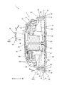
- FIG. 5 is a sectional view taken along line VV in FIG. 4. It is another perspective view of an air blower.
- the blower 1 is illustrated as an example of the blower according to the present invention.
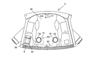
- the outerwear 9 is illustrated as clothing which can attach or detach the air blower 1.
- the blower device 1 of the present embodiment is used by being attached to a jacket 9, for example.
- the outer garment 9 is a front-opening and long-sleeved garment composed mainly of clothing 90.
- the clothing 90 includes left and right front bodies, back bodies, and sleeves, and covers the upper body of the wearer.
- the outerwear 9 is generally worn on an underwear, a T-shirt or the like.
- the clothing material 90 has attachment holes 91 for attaching the blower device 1 at two locations below the back body (specifically, the portion covering the back side around the user's waist when worn). That is, two air blowers 1 can be attached to the jacket 9.
- the attachment hole 91 is comprised as a circular through-hole with the substantially same diameter as the largest diameter of the main-body part 31 (refer FIG. 3) of the air blower 1.
- the peripheral edge portion of the attachment hole 91 is also referred to as a fan attachment portion 93.
- the fan attachment part 93 is reinforced with a reinforcing material so that the blower 1 can be stably attached.
- a pocket 94 is provided in the outer garment 9 (for example, the front body). The pocket 94 can accommodate a battery holder 81 to which a battery 8 as a power source for the blower 1 is mounted.
- the battery holder 81 and the two air blowers 1 are electrically connected by a bifurcated connection cable 83.
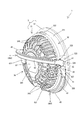
- the blower 1 includes a housing 3 that houses a motor 21 and a fan 23 (see FIG. 5), and two clamp members 4 supported by the housing 3.
- the housing 3 is configured as a substantially circular container corresponding to the shape of the fan 23 when viewed in the direction of the rotation axis A ⁇ b> 1 of the fan 23.
- An intake port 330 (see FIG. 1) penetrating the housing 3 is provided at one end of the housing 3 in the direction of the rotation axis A1.
- an exhaust port 340 penetrating the housing 3 is provided at the other end of the housing 3.
- annular flange portion 37 protruding outward in the radial direction is provided at the end portion of the housing 3 on the same side as the air inlet 330.
- Each clamp member 4 is formed in an arc shape generally corresponding to a semicircle.
- the two clamp members 4 are connected to the housing 3 at both ends.
- the two clamp members 4 are rotatable between a position close to the flange portion 37 and facing the flange portion 37 and a position further away from the flange portion 37.
- the air blower 1 is in a state in which the air inlet 330 faces the outside of the jacket 9 and the flange portion 37 is disposed on the outer surface side of the jacket 9 (that is, the side opposite to the wearer's body).
- a part of the housing 3 is inserted into the inside of the outer garment 9 (that is, the wearer's body side) through the attachment hole 91.
- the clothing material 90 (specifically, the fan mounting portion 93 around the mounting hole 91) is sandwiched between the clamp member 4 and the flange portion 37 that are disposed to face each other. Thereby, the air blower 1 is attached to the jacket 9.
- the blower device 1 sucks air from the outside of the jacket 9 through the intake port 330 and sends it out from the exhaust port 340 toward the inside of the jacket 9.
- the air sent to the inside of the outer garment 9 flows inside the outer garment 9 while cooling the user's body, and flows out of the outer garment 9 from the neck and cuffs.
- the direction of the blower 1 is defined based on the orientation of the user when the blower 1 is attached to the outer garment 9 and the outer garment 9 is further worn.
- the extending direction of the rotation axis A1 of the fan 23 is defined as the front-rear direction.
- the outer surface side of the jacket 9 that is, the intake port 330 and the flange 37 side of the housing 3
- the inner surface side of the jacket 9 that is, the exhaust port 340 side of the housing 3) is the front side.
- blower 1 a detailed configuration of the blower 1 will be described.
- the motor 21 and the fan 23 housed in the housing 3 will be described.
- a relatively small and high output brushless motor is employed as the motor 21.
- an axial fan having a plurality of blades is employed as the motor 21.
- the fan 23 is coaxially attached to a motor shaft 211 that rotates together with the rotor of the motor 21.
- the fan 23 is rotated integrally with the motor shaft 211 around the rotation axis A ⁇ b> 1 of the motor shaft 211 as the motor 21 is driven.
- the battery holder 81 (see FIG. 2) is provided with operation buttons (not shown) for inputting instructions to start and stop the blower 1 (specifically, the motor 21). ing.
- the operation button can also input an instruction for setting the rotation speed of the motor 21. Then, drive control of the motor 21 is performed by a controller (for example, a microcomputer including a CPU, not shown) mounted on the battery holder 81 in accordance with the set rotational speed.
- a controller for example, a microcomputer including a CPU, not shown
- the housing 3 includes a main body portion 31 that houses the motor 21 and the fan 23, and an annular flange portion 37 that protrudes radially outward from the main body portion 31 with respect to the rotation axis A ⁇ b> 1.
- the main body portion 31 includes a cylindrical portion 32, an intake side cover portion 33, and an exhaust side cover portion 34.
- the housing 3 of the present embodiment is made of resin.
- the cylindrical portion 32 has a wall portion formed in a cylindrical shape.
- the cylindrical portion 32 is disposed so as to surround a part of the fan 23 so as to be coaxial with the rotation axis A ⁇ b> 1 of the fan 23.
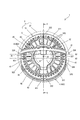
- the cylindrical portion 32 has a shape in which an outer peripheral portion of a cylinder having a predetermined outer diameter D is partially cut out.
- the outer diameter D is the maximum diameter of the main body 31.
- the cylindrical portion 32 has a part of a circle C having the same diameter as the outer diameter D around the rotation axis A1 when viewed in the direction of the rotation axis A1 (when viewed from the front side (exhaust side) or has a cross-sectional shape).
- the cylindrical portion 32 includes a pair of cylindrical surfaces 321 corresponding to the outer peripheral surface of a cylinder having an outer diameter D, and a pair of notch surfaces 325 facing each other substantially in parallel with the rotation axis A1 interposed therebetween. .
- Each notch surface 325 is formed in a planar shape having a normal line orthogonal to the rotation axis A1 as a whole. The distance between the pair of notch surfaces 325 is smaller than the outer diameter D.
- the clamp member 4 is connected to a wall portion (hereinafter referred to as a notch portion 324) in which the notch surface 325 is formed in the cylindrical portion 32.
- the cylindrical portion 32 is provided with a configuration for locking the clamp member 4 at a predetermined position. This point will be described in detail later.
- the intake side cover portion 33 is arranged so as to cover an end portion (that is, a rear end portion) located on the intake side of the fan 23 in the direction of the rotation axis A1.
- the intake side cover portion 33 includes a plate-like closing portion 331 and a plurality of ribs 333.
- the blocking part 331 is disposed at the center as viewed from the rear side.
- the plurality of ribs 333 extend substantially radially from the closing portion 331 and are connected to the rear end portion of the tubular portion 32.
- An opening defined by the closing portion 331, the plurality of ribs 333, and the rear end portion of the tubular portion 32 constitutes the intake port 330.
- the intake port 330 passes through the intake side cover portion 33 in the direction of the rotation axis A1.
- the exhaust side cover part 34 is disposed so as to cover the end part (that is, the front end part) located on the exhaust side of the fan 23 in the direction of the rotation axis A ⁇ b> 1 with respect to the cylindrical part 32.
- the exhaust side cover part 34 is formed in the circular dome shape which protrudes in the direction (front) which leaves
- the exhaust side cover part 34 includes a disk-shaped blocking part 341 and a plurality of ribs 343.
- the blocking part 341 is disposed at the center as viewed from the front side.
- the plurality of ribs 343 generally extend in an arc shape from the closing portion 341 and are connected to the front end portion of the tubular portion 32.
- An opening defined by the closing portion 341, the plurality of ribs 343, and the front end portion of the tubular portion 32 constitutes the exhaust port 340.
- the exhaust port 340 passes through the exhaust-side cover portion 34 in the direction of the rotation axis A1 and in the direction intersecting with the rotation axis A1.
- the flange portion 37 is an annular portion that protrudes radially outward from the rear end portion of the tubular portion 32.
- the front surface of the flange portion 37 is formed in a planar shape that is substantially orthogonal to the rotation axis A1.
- the front surface of the flange portion 37 faces the clamp member 4 disposed at the clamp position and functions as a clamping surface that clamps the clothing material 90 (fan mounting portion 93).
- a recess 345 is provided in a part of the exhaust side cover 34 in the circumferential direction.
- a connector 346 electrically connected to the motor 21 is disposed on the rotation axis A1 side with respect to the recess 345.
- the connector 831 (see FIG. 1) of the connection cable 83 connected to the battery holder 81 is disposed in the recess 345 and connected to the connector 346, so that the battery holder 81 and the blower 1 are electrically connected. Connected.
- each clamp member 4 is supported by the housing 3.
- Each clamp member 4 is formed in an arc shape generally corresponding to a semicircle.
- Each clamp member 4 is made of resin.
- the clamp member 4 includes two end portions 41, a connection portion 43, and a presser portion 45.
- the two end portions 41 are rotatably connected to the cylindrical portion 32 through protrusions inserted into support holes provided in the notch portions 324.
- the connecting portion 43 is an arc-shaped portion that connects the two end portions 41.
- the connection part 43 is made into the circular arc shape corresponding to the periphery of the circle
- the presser portion 45 is a portion that protrudes from the connection portion 43 in the direction intersecting the connection portion 43 over the entire length of the connection portion 43. Note that at least the end portion 41 and the connection portion 43 of the clamp member 4 have radial flexibility.
- Each clamp member 4 is connected to the notch 324 via the two end portions 41 as described above, and is rotatable about a predetermined rotation axis. More specifically, the two clamp members 4 are respectively It is supported so as to be rotatable around rotation axes A2 and A3 which are orthogonal to the rotation axis A1 and parallel to each other.
- the rotation axes A2 and A3 are arranged symmetrically with respect to the rotation axis A1, and extend so as to be substantially orthogonal to the central portion of the pair of notch surfaces 325.
- the clamp member 4 that can rotate around the rotation axis A ⁇ b> 2 is also referred to as a clamp member 402, and the clamp member 4 that can rotate around the rotation axis A ⁇ b> 3 is also referred to as a clamp member 403.
- the clamp member 402 and the clamp member 403 are generically referred to, or when any one is pointed out without distinction, it is simply referred to as the clamp member 4.
- the both ends 41 of each clamp member 4 are arrange
- both end portions 41 of each clamp member 4 are arranged inside the circle C having the same diameter as the outer diameter D around the rotation axis A1 when the housing 3 is viewed in the direction of the rotation axis A1 (from the front side (exhaust side)). Is located.
- each clamp member 4 is configured to be rotatable between a clamp position and a retracted position.
- the clamp position is a position where the clamp member 4 faces the flange portion 37 of the cylindrical portion 32 in the direction of the rotation axis A1 (front-rear direction), and is a position where the clothing material 90 can be clamped together with the flange portion 37. .
- the connection portion 43 is disposed along the cylindrical surface 321.
- the pressing portion 45 protrudes from the connecting portion 43 to the outside in the radial direction of the cylindrical portion 32, faces the front surface of the flange portion 37, and extends in an arc shape along the flange portion 37.
- one surface of the presser portion 45 faces the front surface of the flange portion 37 substantially in parallel and functions as a clamping surface for clamping the clothing material 90.
- the distance between the presser portion 45 and the flange portion 37 in the direction of the rotation axis A1 (the front-rear direction) is the clothing 90 (both the fan attachment portion 93 including the reinforcing material).
- the clothing 90 both the fan attachment portion 93 including the reinforcing material
- the retracted position is a position where the clamp member 4 is farther from the flange portion 37 than the clamp position, and is a position where the clothing material 90 cannot be clamped together with the flange portion 37.
- the retracted position is a position where the central portion of the connection portion 43 faces the closing portion 341 of the exhaust side cover portion 34.
- the two clamp members 4 rotate in directions away from each other (rearward) toward the respective clamp positions, and in directions closer to each other (frontward) toward the respective retracted positions. It is configured to rotate.
- the direction from the retracted position to the clamp position (the direction indicated by the arrow A in FIG. 5) is the clamp direction
- the direction from the clamp position to the retracted position (the arrow B in FIG. 5).
- the direction indicated by) is referred to as the retreat direction.
- the main body 31 is provided with a configuration for locking each clamp member 4 at the clamp position and a configuration for locking at the retracted position.
- the cylindrical portion 32 has two locking recesses 322. More specifically, each locking recess 322 is formed at the center front end of the cylindrical surface 321.
- a locking piece 431 that protrudes forward when the clamp member 4 is disposed at the clamp position is provided at the center of the connection portion 43 of the clamp member 4.
- the locking piece 431 is formed in a rectangular plate shape, and is arranged so that the normal line thereof is substantially orthogonal to the rotation axes A2 and A3.
- the locking piece 431 has flexibility in the normal direction.
- a claw 432 is provided on the inner surface of the locking piece 431 (the surface disposed on the housing 3 side).
- the claw 432 enters the locking recess 322 and engages with the locking recess 322 (see the clamp member 403).
- the clamp member 4 is locked (held) at the clamp position.
- “locked” here is not limited to being held in a state in which it is completely immovable, but also includes holding in a state where some movement is allowed.
- the clamp member 4 When moving the clamp member 4 at the clamp position to the retracted position, the user flexes the locking piece 431 outward in the radial direction of the cylindrical portion 32 to release the locking of the claw 432 with respect to the locking recess 322,
- the clamp member 4 may be rotated in the retracting direction (the direction of arrow B in FIG. 5).
- two locking projections 326 are provided at one front end portion of the pair of notch portions 324 provided in the cylindrical portion 32.
- the two locking projections 326 are provided at both ends in the circumferential direction of the notch surface 325.
- Each locking protrusion 326 is a substantially hemispherical protrusion that protrudes radially outward from the notch surface 325, and the protrusion amount is considerably smaller than the thickness of the end portion 41.
- the two locking projections 326 are arranged at positions where they come into contact with the end portions 41 of the two clamp members 4 arranged at the respective clamping positions on the retracting direction side.
- each locking protrusion 326 abuts against the clamp member 4, thereby restricting the clamp member 4 (see the clamp member 403) at the clamp position from rotating in the retracting direction.
- each clamp member 4 is locked at the clamp position mainly by the engagement of the locking piece 431 and the locking recess 322 described above. Therefore, the locking projection 326 is provided on only one of the pair of cutout portions 324 corresponding to one end 41 of each clamp member 4 and functions as an auxiliary locking mechanism.
- the end portion 41 gets over the locking projection 326 while slightly bending outward in the radial direction of the cylindrical portion 32. That is, the locking by the locking protrusion 326 is released with the turning operation of the clamp member 4 to the retracted position.
- the protruding amount of the locking projection 326 is small, the locking of the locking projection 326 can be easily released in accordance with the turning operation.
- the above-described locking projection 326 protruding from the notch surface 325 is configured to be able to lock the clamp member 4 even in the retracted position. More specifically, as shown in FIG. 3, the locking protrusion 326 is brought into contact with the end 41 of the clamp member 4 disposed at the retracted position on the clamp direction side, so that the clamp member 4 at the retracted position is located. Restricts rotation in the clamping direction. Further, a stopper 327 configured to restrict further rotation of the clamp member 4 in the retracted position in the retracted direction is provided at the front end of the notch 324. As shown in FIG.
- the stopper 327 is configured as a substantially triangular prism-shaped protrusion that protrudes radially outward from the notch surface 325.
- the stopper 327 is arranged in such a direction that the two side surfaces of the triangular prism expand toward the front (exhaust side).
- the end portion 41 gets over the locking protrusion 326 while slightly bending radially outward as in the case of the rotation to the retracted position.
- the end portion 41 gets over the locking projection 326, the end portion 41 returns to a position where it abuts on the notch surface 325 by its restoring force.
- the clamp member 4 is brought into contact with the locking projection 326 in comparison with the clamp position where the clamp member 4 is locked by the engagement between the locking piece 431 (claw 432) and the locking recess 322. It can be said that the locking at the retracted position to be locked is loose. This is because it is necessary to more securely lock (hold) the clamp member 4 at the clamp position in order to securely hold the clothing material 90 at the clamp position.
- the user When the blower 1 is mounted on the outer garment 9, the user first places both the two clamp members 4 in the retracted position (the position of the clamp member 402 in FIG. 3). As described above, each clamp member 4 is locked at the retracted position by the locking protrusion 326 and the stopper 327. Thereby, when both the two clamp members 4 are viewed in the direction of the rotation axis A1 (from the front side (exhaust side)), the entirety of the two clamp members 4 is a circle C having the same diameter as the outer diameter D around the rotation axis A1. It is arrange
- the user moves a part of the main body 31 in a state where the clamp member 4 is disposed at the retracted position from the outside of the outer jacket 9 through the attachment hole 91 (see FIG. 2) to the inner side of the outer jacket 9 (the front surface of the back body). Side).
- the mounting hole 91 has substantially the same diameter as the maximum diameter (that is, the outer diameter D) of the main body 31, and therefore has the same diameter as the diameter of the circle C (see FIG. 4).
- the clamp member 4 in the retracted position is entirely inside the circle C as viewed from the front side. Therefore, the user can easily and smoothly insert the main body portion 31 from the attachment hole 91 without the clamp member 4 interfering with the fan attachment portion 93.
- the cylindrical part 32 and the exhaust side cover part 34 of the housing 3 and the clamp member 4 are placed inside the outer jacket 9 in a state where the flange part 37 is in contact with the outer surface of the back body (fan mounting part 93). Be placed.
- the user releases both of the locking projections 326 from the clamping member 4 as described above, while holding the two clamping members 4 in the clamping position (the clamping member in FIG. 5). 403). Then, the clamp member 4 is locked at the clamp position by engaging the locking piece 431 with the locking recess 322. As a result, the clothing material 90 (fan mounting portion 93) is sandwiched from the front side and the rear side by the clamp member 4 and the flange portion 37, and the mounting of the blower device 1 on the outer garment 9 is completed.
- the user can remove the blower device 1 from the jacket 9 in the reverse order of the wearing. Specifically, the user first releases the engagement between the locking piece 431 and the locking recess 322 inside the outer garment 9 and rotates the clamp member 4 to the retracted position in the retracting direction. The clamp member 4 is locked at the retracted position by the locking protrusion 326 and the stopper 327. In this state, the user pulls out the housing 3 inserted into the attachment hole 91 from the outside of the outer jacket 9. Also at this time, as in the case of mounting, the user can easily and smoothly pull out the main body portion 31 from the mounting hole 91 without the clamp member 4 disposed at the retracted position interfering with the fan mounting portion 93. Thereby, the removal from the jacket 9 of the air blower 1 is completed.
- the blower device 1 of this embodiment is configured so that the clothing material 90 (fan mounting portion 93) is sandwiched between the clamp member 4 that is locked at the clamp position and the flange portion 37 of the housing 3. It is configured.
- the clamp member 4 is not separated from the housing 3 but supported by the housing 3 (tubular portion 32) so as to be rotatable. Therefore, the user can easily attach and detach the blower 1 to the clothing material 90 (fan mounting portion 93) only by rotating the clamp member 4 between the clamp position and the retracted position. 2.
- an air blower having a structure in which a ring-shaped member separate from a housing is fitted into a housing having a flange portion, and clothes are sandwiched between the flange portion and the ring-shaped member.
- the claw 432 of the locking piece 431 engages with the locking recess 322 as the clamping member 4 rotates to the clamping position, and the clamping member 4 is engaged at the clamping position. Stopped. That is, the user only needs to perform the rotation operation to the clamp position, and does not need to perform an individual operation for locking the clamp member 4 at the clamp position. Further, unlike the conventional blower, it is not necessary to align the housing and the ring-shaped member separate from the housing at a predetermined locking position. Thus, in the air blower 1, the latching structure with a high convenience for a user is implement
- the two clamp members 4 are provided, and each of the clamp members 4 is locked at the clamp position through the engagement of the locking piece 431 and the locking recess 322. Therefore, compared with the case where there is only one clamp member 4, the blower device 1 can be more reliably attached to the clothing material 90.
- the two clamp members 4 are rotatable around parallel rotation axes A2 and A3, rotate in directions away from each other toward the respective clamp positions, and toward the respective retracted positions. It is comprised so that it may rotate in the direction which mutually approaches. With such a configuration, a compact and rational arrangement of the two clamp members 4 is realized.
- the clamp member 4 includes a presser portion 45 configured to extend in an arc shape facing the flange portion 37 when disposed at the clamp position. Therefore, the clothing material 90 can be stably held by the flange portion 37 and the presser portion 45. Furthermore, in the present embodiment, the two clamp members 4 are configured to oppose substantially the entire circumference of the flange portion 37, so that the clothing 90 can be held more stably.
- the clamp member 4 is locked at the retracted position by the locking protrusion 326 and the stopper 327. Therefore, the clamp member 4 can be locked at the retracted position so as not to interfere with the attaching / detaching operation to the outer jacket 9 of the blower 1.
- the entire clamp member 4 disposed at the retracted position is the maximum diameter (outer diameter D) of the cylindrical portion 32. It is inside the circle C of the same diameter. Further, the clamp member 4 arranged at the retracted position is entirely inside the attachment hole 91 provided in the outer jacket 9.
- the outer garment 9, the clothing material 90, and the attachment hole 91 are examples of “clothes”, “clothing”, and “opening” of the present invention, respectively.
- the blower 1 is an example of the “blower” of the present invention.
- the fan 23 is an example of the “fan” in the present invention.
- the housing 3, the main body 31, and the flange portion 37 are examples of the “housing”, the “fan accommodating portion”, and the “projecting portion” of the present invention, respectively.
- the clamp member 4 is an example of the “clamp member” in the present invention.
- the locking piece 431 (claw 432) and the locking recess 322 are examples of the “locking portion” of the present invention.
- the flange portion 37 is an example of the “flange portion” in the present invention.
- the locking protrusion 326 and the stopper 327 are examples of the “additional locking portion”.
- the cylindrical portion 32 is an example of the “tubular portion” in the present invention.
- the end 41 is an example of the “end” in the present invention.
- the air blower and clothes according to the present invention are not limited to the configurations of the air blower 1 and the jacket 9 illustrated.
- the changes exemplified below can be added. It should be noted that any one or more of these changes may be employed in combination with the blower 1, the jacket 9, or the invention described in each claim.
- the clamp member 4 only needs to be supported by the housing 3 so as to be rotatable between a clamp position and a retracted position, and the configuration thereof can be changed as appropriate.
- the flange part 37 should just be able to clamp the clothing material 90 with the clamp member 4 arrange
- the number of the clamp members 4 may be one, or may be three or more.
- only the clamp member 402 of the above embodiment may be provided.
- the cylindrical portion 32 may be provided with an arcuate protrusion corresponding to the pressing portion 45 when the clamp member 403 is disposed at the clamp position.
- the clamp member 402 is clamped after the main body 31 is inserted into the mounting hole 91 in a state where a part of the fan mounting portion 93 is sandwiched between the protruding portion and the flange portion 37 facing the protruding portion. What is necessary is just to be rotated to a position. Thereby, the clothing material 90 can be clamped similarly to the clamp members 402 and 403 and the flange portion 37 of the above embodiment.
- the shape of the clamp member 4 and the manner of connection to the housing 3 are not limited to the above-described embodiment.
- a plurality of clamp members may be rotatably supported by the closing portion 341 of the exhaust side cover portion 34 at each one end portion.
- the clamp member disposed at the clamp position extends radially along the rib 343 and the presser portion provided at the other end can sandwich the clothing material 90 between the flange portion 37. .
- the flange portion 37 does not necessarily have to surround the cylindrical portion 32 in an annular shape over the entire circumference, and the housing 3 has a protruding portion that protrudes radially outward so as to face the clamp member 4 disposed at the clamp position. What is necessary is just to be provided.
- the flange portion 37 may have a portion corresponding to the notch portion 324 (that is, a portion that does not face the pressing portion 45) cut out (that is, substantially formed in an annular shape). Also good).
- a plurality of protruding portions that protrude radially from the outer peripheral portion of the cylindrical portion 32 may be provided.
- the flange portion 37 may be provided not at the rear end portion of the tubular portion 32 but at the central portion.
- both portions are configured to be able to sandwich the clothing 90.
- the edge part 41 connected with the housing 3 is the maximum diameter ( It is inside the circle C having the same diameter as the outer diameter D).
- the end 41 does not necessarily have to be inside the circle C.
- the cylindrical portion 32 may be formed in a cylindrical shape having the outer diameter D without including the notch portion 324. In this case, the end 41 is disposed outside the circle C.
- the clamp member 4 disposed at the retracted position does not necessarily have to be entirely inside the circle C.
- the end 41 and the clamp member 4 at the retracted position are in the direction of the rotation axis A1 ( Even if it is outside the circle C as viewed from the front side, if it is inside the mounting hole 91, the main body 31 can be easily and smoothly inserted into the mounting hole 91 as in the above embodiment.
- the structure for locking the clamp member 4 to the housing 3 at the clamp position is not limited to the locking piece 431 (claw 432), the locking recess 322, and the locking protrusion 326.
- a configuration that can be engaged with a part of the clamp member 4 may be provided in the housing 3 or as a separate body from the housing 3.
- the structure which engages with a part of clamp member 4 according to rotation to the clamp position of the clamp member 4 is preferable.
- the main body 31 may be provided with a flexible locking piece, and the claw of the locking piece may be engageable with a locking recess provided in the clamp member 4.
- the main body 31 may be provided with, for example, a rotating fastener.
- the blower 1 can be attached to and detached from a plurality of types of clothes having different thicknesses. Therefore, the configuration for locking the clamp member 4 to the housing 3 at the clamp position is in the direction of the rotation axis A1 between the clamp member 4 disposed at the clamp position and the flange portion 37 according to the thickness of the clothing.
- the distance may be adjustable.
- the locking recess 322 may include a plurality of grooves having a V-shaped cross section formed along the direction of the rotation axis A1. In this case, the nail
- the configuration for locking the clamp member 4 with respect to the housing 3 at the retracted position may be changed similarly to the configuration for locking at the clamp position, or may be omitted.
- the engaging piece 431 of the clamp members 402 and 403 may be provided with a convex portion and a concave portion that engage with each other when the clamp members 402 and 403 are disposed at the retracted position. That is, the structure for locking at the retracted position may be provided only on the clamp member 4.
- the shapes of the cylindrical portion 32, the intake side cover portion 33, and the exhaust side cover portion 34, and the number and positions of the intake ports 330 and the exhaust ports 340 may be changed.
- a motor having a brush may be employed instead of the brushless motor.
- a configuration in which a plurality of fans 23 are accommodated in one housing 3 may be employed. In this case, a plurality of motors 21 may be provided corresponding to the number of fans 23.
- the garment according to the present invention does not necessarily need to be a long-sleeved upper garment such as a jacket 9.
- a hooded garment for example, it can be suitably realized as a hooded garment, a sleeveless garment (vest), a so-called coverall that connects the garment and trousers, or trousers.
- the use of clothes is not particularly limited, and can be realized as, for example, work clothes, sportswear, leisure wear, fire fighting clothes, protective clothes, and surgical clothes.
- the clothes may be provided with a two-layer structure of outer and lining.
- the attachment hole 91 may be provided in the front surface, and when the blower 1 is mounted, the exhaust side cover 34 may be disposed in the internal space between the front material and the lining material.
- a region (including an opening) having a relatively high air permeability may be appropriately provided on a neck or a side where the necessity for cooling is high, and the wearer's body may be cooled by air flowing out of the region.
- the size and shape of the attachment hole 91 in the clothes can be appropriately changed according to the configuration of the blower device to be mounted. Further, the position and number of the attachment holes 91 (that is, the number of the blower devices 1 that can be attached) and the like can be appropriately changed.
- the rotation shafts of the two clamp members are orthogonal to the rotation axis of the fan and extend symmetrically across the rotation shaft,
- the two clamp members arranged at the clamp position may be arranged in an arc shape along the outer peripheral surface of the cylindrical portion when viewed in the direction of the rotation axis of the fan. According to this aspect, it is possible to realize a compact and rational arrangement of the clamp member with respect to the cylindrical portion.
- the locking portion may include a convex portion provided on one of the clamp member and the fan accommodating portion, and a concave portion provided on the other of the clamp member and the fan accommodating portion. According to this aspect, it is possible to provide the clamp member and the housing with the locking portion having a simple and compact configuration.
- claw 432 and the latching recessed part 322 of the said embodiment are examples of the "convex part” and “recessed part” of this aspect, respectively.
- the convex portion and the concave portion may be configured to engage with each other as the clamp member rotates to the clamp position. According to this aspect, the clamp member can be locked at the clamp position only by the user turning the clamp member to the clamp position.
Landscapes
- Engineering & Computer Science (AREA)
- Mechanical Engineering (AREA)
- General Engineering & Computer Science (AREA)
- Environmental & Geological Engineering (AREA)
- Health & Medical Sciences (AREA)
- General Health & Medical Sciences (AREA)
- Physical Education & Sports Medicine (AREA)
- Textile Engineering (AREA)
- Professional, Industrial, Or Sporting Protective Garments (AREA)
- Structures Of Non-Positive Displacement Pumps (AREA)
Abstract
衣服への着脱時の操作が容易な送風装置を提供する。 送風装置1は、ファンと、ハウジング3と、クランプ部材4と、係止片431および係止凹部322とを備える。ハウジング3は、本体部31とフランジ部37とを含む。本体部31は、ファンを収容するとともに、衣服の服地に設けられた開口部に一部が挿通可能に構成されている。フランジ部37は、本体部31からファンの回転軸に対して径方向外側に突出する。クランプ部材4は、フランジ部37に対向してフランジ部37と共に服地を挟持可能なクランプ位置と、クランプ位置よりもフランジ部37から離れた退避位置との間で回動可能にハウジング3に支持されている。係止片431および係止凹部322は、クランプ部材4をハウジング3に対してクランプ位置で係止するように構成されている。
Description
本発明は、衣服に着脱可能な送風装置および送風装置を備えた衣服に関する。
衣服に取り外し可能に装着され、衣服内に送風することにより衣服内を通気する送風装置が知られている。例えば、国際公開第2007/061088号には、ファン本体部とリング状部材とを備えた送風装置が開示されている。ファン本体部は、吸気口および排気口を有し、モータおよびファンを収容するケース部と、ケース部の吸気口の周りに形成されたフランジ部とを有する。この送風装置は、次のようにして衣服に装着される。まず、ケース部が衣服に設けられた開口部に外側から挿入され、フランジ部が衣服の外側で開口部の周縁部に当接するように配置される。衣服の内側からリング状部材がケース部に嵌め込まれると、フランジ部とリング状部材の間に服地が挟持され、装着が完了する。
上記送風装置を衣服に取り付ける場合、使用者は、ファン本体部と、ファン本体部とは別体のリング状部材を、分離したり嵌め込んだりする必要がある。このため、使用者によっては、着脱時の操作が煩わしいと感じる場合があり、この送風装置には、更なる改善の余地がある。
本発明は、このような事情に鑑みてなされたものであり、衣服への着脱時の操作が容易な送風装置を提供することを目的とする。
本発明の一態様として、衣服の服地に着脱可能に構成された送風装置が提供される。この送風装置は、ファンと、ハウジングと、少なくとも1つのクランプ部材と、少なくとも1つの係止部とを備えている。
ハウジングは、ファン収容部と、突出部とを含む。ファン収容部は、ファンを収容するとともに、服地に設けられた開口部に一部が挿通可能に構成されている。突出部は、ファン収容部からファンの回転軸に対して径方向外側に突出している。少なくとも1つのクランプ部材の各々は、クランプ位置と退避位置との間で回動可能にハウジングに支持されている。クランプ位置では、クランプ部材は、突出部に対向して、突出部と共に衣服の服地を挟持可能である。退避位置では、クランプ部材は、クランプ位置よりも突出部から離れた位置にある。少なくとも1つの係止部は、少なくとも1つのクランプ部材をハウジングに対してクランプ位置で係止するように構成されている。
本態様の送風装置は、ハウジングの突出部と、少なくとも1つのクランプ部材で服地を挟持するように構成されている。少なくとも1つのクランプ部材は、ハウジングと別体ではなく、ハウジングに回動可能に支持されている。よって、使用者は、少なくとも1つのクランプ部材をハウジングから取り外したり嵌め込んだりする必要がなく、少なくとも1つのクランプ部材をクランプ位置と退避位置との間で回動させる操作をするだけで、送風装置を衣服に容易に着脱することができる。なお、本態様でいう「少なくとも1つのクランプ部材をクランプ位置で係止する」とは、少なくとも1つのクランプ部材を、クランプ位置において移動不能に保持することだけでなく、クランプ位置からの若干の移動を許容しつつ保持することも含む意である。
本発明の一態様において、少なくとも1つのクランプ部材は、2つのクランプ部材を含んでいてもよい。そして、少なくとも1つの係止部は、2つのクランプ部材を夫々のクランプ位置で係止するように構成された2つの係止部を含んでいてもよい。本態様によれば、回動式の2つのクランプ部材を用いて服地を挟持できるため、クランプ部材が1つのみの場合に比べ、送風装置をより確実に服地に装着することができる。更に、本態様において、2つのクランプ部材は、夫々の回動軸が互いに平行となるように配置されていてもよい。そして、2つのクランプ部材は、夫々のクランプ位置に向かって互いに離れる方向に回動し、且つ、夫々の退避位置に向かって互いに近づく方向に回動するように構成されていてもよい。この場合、2つのクランプ部材のコンパクトで合理的な配置を実現することができる。
本発明の一態様において、ハウジングの突出部は、概ね環状に形成されたフランジ部を含んでもよい。そして、少なくとも1つのクランプ部材の各々の少なくとも一部は、クランプ位置に配置された場合、フランジ部に対向して円弧状に延在するように構成されていてもよい。本態様によれば、フランジ部と、クランプ部材の円弧状の部分によって、安定して服地の挟持を維持することができる。なお、本態様において、少なくとも1つのクランプ部材は、クランプ位置に配置された場合、環状のフランジ部の概ね全周に対向するように構成されていると、より好ましい。
本発明の一態様において、送風装置は、少なくとも1つのクランプ部材をハウジングに対して退避位置で係止するように構成された付加係止部を更に備えていてもよい。本態様によれば、少なくとも1つのクランプ部材を、クランプ位置のみならず、退避位置でも係止することができる。よって、送風装置の衣服への着脱操作の邪魔にならないように、少なくとも1つのクランプ部材を退避位置で係止しておくことができる。なお、本態様でいう「少なくとも1つのクランプ部材を退避位置で係止する」とは、少なくとも1つのクランプ部材を、退避位置において移動不能に保持することだけでなく、退避位置からの若干の移動を許容しつつ保持することも含む意である。
本発明の一態様において、ファン収容部は、筒状部を含んでもよい。筒状部は、ファンの回転軸と同軸状に配置され、開口部に挿通される部分である。筒状部は、所定の外径を有する円筒の外周部が部分的に切り欠かれた形状を有していてもよい。少なくとも1つのクランプ部材の各々は、筒状部のうち、部分的に切り欠かれた部分に連結された端部を有してもよい。そして、送風装置を回転軸の方向にみた場合、端部は、回転軸を中心とする、所定の外径と同径の円の内側に位置するとよい。本態様によれば、クランプ部材のうち、筒状部に連結された端部は、筒状部の最大径と同径の円よりも内側にある。よって、筒状部が服地の開口部に挿通されるときに、少なくとも、端部が服地に干渉することを回避でき、送風装置の衣服への着脱操作をより容易にすることができる。更に、本態様において、送風装置を回転軸の方向にみた場合、退避位置に配置された少なくとも1つのクランプ部材は、全体が円の内側に位置すると、より好ましい。この場合、少なくとも1つのクランプ部材を退避位置に配置しておくことで、筒状部が服地の開口部に挿通されるときに、少なくとも1つのクランプ部材の全体が服地に干渉することを回避でき、送風装置の衣服への着脱操作を更に容易に且つスムーズにすることができる。
本発明の一態様によれば、服地と、送風装置とを備えた衣服が提供される。服地は、着用者の身体の少なくとも一部を覆うように構成されている。また、服地は、開口部を有する。送風装置としては、上述の態様のうち何れか1つ、または複数の組み合わせに係る送風装置が採用されうる。この衣服においては、送風装置の一部が開口部に挿通された状態で、クランプ位置に配置された少なくとも1つのクランプ部材と突出部とが開口部周りで服地を挟持することで、送風装置が服地に取り付けられる。本態様によれば、上述のように、回動式の少なくとも1つのクランプ部材によって容易に着脱可能な送風装置を備えた衣服が提供される。
本発明の一態様において、ファン収容部は、筒状部を含んでもよい。筒状部は、ファンの回転軸と同軸状に配置され、開口部に挿通される部分である。少なくとも1つのクランプ部材の各々は、筒状部に連結された端部を有してもよい。この衣服においては、筒状部の一部が開口部に挿通された状態で、クランプ位置に配置された少なくとも1つのクランプ部材と突出部とが開口部周りで服地を挟持することで、送風装置が服地に取り付けられる。そして、服地に取り付けられた送風装置を回転軸の方向にみた場合、端部は、開口部の内側に位置していると、好ましい。本態様によれば、筒状部が服地の開口部に挿通されるときに、少なくとも、筒状部に連結された端部が服地に干渉することを回避でき、送風装置の衣服への着脱操作をより容易にすることができる。更に、本態様において、送風装置を回転軸の方向にみた場合、退避位置に配置された少なくとも1つのクランプ部材は、全体が開口部の内側に位置していると、更に好ましい。この場合、少なくとも1つのクランプ部材を退避位置に配置しておくことで、筒状部が服地の開口部に挿通されるときに、少なくとも1つのクランプ部材の全体が服地に干渉することを回避でき、送風装置の衣服への着脱操作を更に容易に且つスムーズにすることができる。
以下、図面を参照して、本発明の実施形態について説明する。なお、以下の実施形態では、本発明に係る送風装置の一例として、送風装置1を例示する。また、送風装置1を着脱可能な衣服として、上着9を例示する。
まず、図1および図2を参照して、本実施形態の上着9および送風装置1の概略構成と、送風装置1の使用態様について、簡単に説明する。
図1に示すように、本実施形態の送風装置1は、例えば、上着9に装着されて使用される。図2に示すように、上着9は、服地90を主体として構成された、前開きで長袖の上衣である。服地90は、左右の前身頃、後身頃、および袖を含み、着用者の上半身を覆う。上着9は、一般的には、下着やTシャツ等の上に着用される。服地90は、後身頃の下方(詳細には、着用時に使用者の腰周りの背中側を覆う部分)の2箇所に、送風装置1を取り付けるための取付け孔91を有する。つまり、上着9には、2つの送風装置1が取り付け可能である。なお、取付け孔91は、送風装置1の本体部31(図3参照)の最大径と概ね同径の円形の貫通孔として構成されている。以下、取付け孔91の周縁部を、ファン取付け部93ともいう。なお、ファン取付け部93は、送風装置1を安定して取り付け可能とするために、補強材によって補強されていることが好ましい。また、上着9(例えば、前身頃)には、ポケット94が設けられている。ポケット94は、送風装置1の電源としてのバッテリ8が装着されたバッテリホルダ81を収容可能である。バッテリホルダ81と2つの送風装置1は、二股状の接続ケーブル83によって電気的に接続される。
図3~図5に示すように、送風装置1は、モータ21およびファン23(図5参照)を収容するハウジング3と、ハウジング3に支持された2つのクランプ部材4とを備えている。ハウジング3は、ファン23の形状に対応して、ファン23の回転軸A1方向にみて概ね円形の収容体として構成されている。ハウジング3の回転軸A1方向における一端部には、ハウジング3を貫通する吸気口330(図1参照)が設けられている。一方、ハウジング3の他端部には、ハウジング3を貫通する排気口340が設けられている。また、ハウジング3の吸気口330と同じ側の端部には、径方向外側に突出する環状のフランジ部37が設けられている。各クランプ部材4は、全体としては、半円に概ね対応する円弧状に形成されている。2つのクランプ部材4は、夫々の両端部においてハウジング3に連結されている。2つのクランプ部材4は、フランジ部37に近接してフランジ部37に対向する位置と、フランジ部37からより離れた位置との間で回動可能である。
本実施形態では、送風装置1は、吸気口330が上着9の外部を臨み、フランジ部37が上着9の外面側(つまり、着用者の身体とは反対側)に配置された状態で、ハウジング3の一部が取付け孔91を通して上着9の内部(つまり、着用者の身体側)に挿入される。そして、対向配置されたクランプ部材4とフランジ部37とによって、服地90(詳細には、取付け孔91周りのファン取付け部93)が挟持される。これにより、送風装置1が上着9に装着される。送風装置1は、吸気口330を介して上着9の外部から空気を吸い込み、排気口340から上着9の内部へ向けて送出する。上着9の内部へ送出された空気は、使用者の身体を冷却しつつ上着9の内部を流れ、襟元や袖口から上着9の外部へ流出する。送風装置1の装着によって上着9内を通気可能とすることで、使用者は高温下においても快適な作業環境を得ることができる。
なお、以下の説明では、便宜上、送風装置1の方向に関しては、送風装置1が上着9に装着され、更に上着9が着用されたときの使用者の向きを基準として定義する。具体的には、ファン23の回転軸A1の延在方向を前後方向と定義する。前後方向において、上着9の外面側(つまり、ハウジング3の吸気口330およびフランジ部37側)を後側、上着9の内面側(つまり、ハウジング3の排気口340側)を前側とする。
以下、送風装置1の詳細構成について説明する。
まず、ハウジング3内に収容されたモータ21およびファン23について説明する。図5に示すように、本実施形態では、モータ21として、比較的小型で高出力なブラシレスモータが採用されている。また、ファン23として、複数の羽根を備えた軸流ファンが採用されている。ファン23は、モータ21のロータと共に回転するモータシャフト211に同軸状に取り付けられている。ファン23は、モータ21の駆動に伴って、モータシャフト211の回転軸A1周りにモータシャフト211と一体的に回転される。なお、本実施形態では、バッテリホルダ81(図2参照)には、送風装置1(詳細には、モータ21)の駆動開始および停止の指示を入力するための操作ボタン(図示略)が設けられている。また、操作ボタンは、モータ21の回転数の設定のための指示も入力可能とされている。そして、バッテリホルダ81に搭載されたコントローラ(例えば、CPUを備えたマイクロコンピュータ、図示略)によって、設定された回転数に応じてモータ21の駆動制御が行われる。
次に、ハウジング3について説明する。図5に示すように、ハウジング3は、モータ21およびファン23を収容する本体部31と、本体部31から回転軸A1に対して径方向外側に突出する環状のフランジ部37とを含む。本体部31は、筒状部32と、吸気側カバー部33と、排気側カバー部34とを含む。なお、本実施形態のハウジング3は樹脂製である。
図5に示すように、筒状部32は、筒状に形成された壁部を有する。筒状部32は、ファン23の回転軸A1と同軸状に、ファン23の一部を囲むように配置されている。また、図4および図6に示すように、本実施形態では、筒状部32は、所定の外径Dを有する円筒の外周部が部分的に切り欠かれた形状を有する。なお、外径Dは、本体部31の最大径である。筒状部32は、回転軸A1の方向にみて(前側(排気側)からみて、あるいは、断面形状が)、回転軸A1を中心とする、外径Dと同径の円Cの一部が切り欠かれた形状を有するということもできる。より詳細には、筒状部32は、外径Dを有する円筒の外周面に対応する一対の円筒面321と、回転軸A1を挟んで概ね平行に対向する一対の切欠き面325とを有する。各切欠き面325は、全体としては、回転軸A1に直交する法線を有する平面状に形成されている。一対の切欠き面325の間の距離は、外径Dよりも小さい。筒状部32のうち、切欠き面325が形成された壁部(以下、切欠き部324という)には、クランプ部材4が連結されている。
また、本実施形態では、筒状部32には、クランプ部材4を所定位置で係止するための構成が設けられているが、この点については後で詳述する。
図5に示すように、吸気側カバー部33は、回転軸A1方向においてファン23の吸気側に位置する端部(つまり、後端部)を覆うように配置されている。図1に示すように、吸気側カバー部33は、板状の閉塞部331と、複数のリブ333とを含む。閉塞部331は、後側からみて中央部に配置されている。複数のリブ333は、閉塞部331から概ね放射状に延在し、筒状部32の後端部に接続する。閉塞部331と複数のリブ333と筒状部32の後端部によって規定される開口が、吸気口330を構成する。なお、吸気口330は、回転軸A1方向に吸気側カバー部33を貫通している。
図3に示すように、排気側カバー部34は、筒状部32に対し、回転軸A1方向においてファン23の排気側に位置する端部(つまり、前端部)を覆うように配置されている。本実施形態では、排気側カバー部34は、全体としては、回転軸A1方向において筒状部32の前端部から離れる方向(前方)に突出する円形ドーム状に形成されている。排気側カバー部34は、円板状の閉塞部341と、複数のリブ343とを含む。閉塞部341は、前側からみて中央部に配置されている。複数のリブ343は、全体としては閉塞部341から円弧状に延在して筒状部32の前端部に接続する。閉塞部341と複数のリブ343と筒状部32の前端部によって規定される開口が、排気口340を構成する。なお、排気口340は、回転軸A1方向および回転軸A1に交差する方向に排気側カバー部34を貫通している。ファン23が回転駆動されると、後方から前方へ、吸気口330を通ってハウジング3内へ流入した空気は、排気口340を通って、後方から前方へ、また径方向外側へ向かって流出する。
フランジ部37は、筒状部32の後端部から径方向外側に突出する環状の部分である。本実施形態では、フランジ部37の前面は、回転軸A1に概ね直交する平面状に形成されている。フランジ部37の前面は、クランプ位置に配置されたクランプ部材4に対向し、服地90(ファン取付け部93)を挟持する挟持面として機能する。
なお、図5に示すように、排気側カバー部34の周方向における一部には、凹部345が設けられている。凹部345に対して回転軸A1側には、モータ21に電気的に接続されたコネクタ346が配置されている。上述のようにバッテリホルダ81に接続された接続ケーブル83のコネクタ831(図1参照)が凹部345に配置され、コネクタ346に接続されることで、バッテリホルダ81と送風装置1とが電気的に接続される。
以下、クランプ部材4について説明する。図3および図4に示すように、本実施形態では、2つのクランプ部材4がハウジング3に支持されている。各クランプ部材4は、全体としては、半円に概ね対応する円弧状に形成されている。各クランプ部材4は、樹脂製である。クランプ部材4は、2つの端部41と、接続部43と、押え部45とを含む。詳細な図示は省略するが、2つの端部41は、切欠き部324に設けられた支持孔に挿入された突起を介して、筒状部32に対して回動可能に連結されている。接続部43は、2つの端部41を接続する円弧状の部分である。なお、接続部43は、外径Dの円の円周に対応する円弧状とされている(図4参照)。押え部45は、接続部43の全長に亘って、接続部43に交差する方向に接続部43から突出する部分である。なお、クランプ部材4のうち、少なくとも端部41および接続部43は、径方向の可撓性を有している。
各クランプ部材4は、上述のように2つの端部41を介して切欠き部324に連結され、所定の回動軸周りに回動可能とされている。より詳細には、2つのクランプ部材4は、夫々、
回転軸A1に直交し、且つ、互いに平行な回動軸A2、A3周りに回動可能に支持されている。回動軸A2、A3は、回転軸A1を挟んで対称状に配置され、一対の切欠き面325の中央部に概ね直交するように延在する。以下では、回転軸A2周りに回動可能なクランプ部材4をクランプ部材402、回転軸A3周りに回動可能なクランプ部材4をクランプ部材403ともいう。クランプ部材402およびクランプ部材403を総称する場合、または何れか一方を区別なく指す場合、単にクランプ部材4という。なお、図4に示すように、各クランプ部材4の両端部41は、夫々、一対の切欠き面325に当接するように配置されている。また、各クランプ部材4の両端部41は、ハウジング3を回転軸A1の方向に(前側(排気側)から)みた場合、回転軸A1を中心とする外径Dと同径の円Cの内側に位置している。
回転軸A1に直交し、且つ、互いに平行な回動軸A2、A3周りに回動可能に支持されている。回動軸A2、A3は、回転軸A1を挟んで対称状に配置され、一対の切欠き面325の中央部に概ね直交するように延在する。以下では、回転軸A2周りに回動可能なクランプ部材4をクランプ部材402、回転軸A3周りに回動可能なクランプ部材4をクランプ部材403ともいう。クランプ部材402およびクランプ部材403を総称する場合、または何れか一方を区別なく指す場合、単にクランプ部材4という。なお、図4に示すように、各クランプ部材4の両端部41は、夫々、一対の切欠き面325に当接するように配置されている。また、各クランプ部材4の両端部41は、ハウジング3を回転軸A1の方向に(前側(排気側)から)みた場合、回転軸A1を中心とする外径Dと同径の円Cの内側に位置している。
本実施形態では、各クランプ部材4は、クランプ位置と退避位置との間で回動可能に構成されている。
クランプ位置とは、クランプ部材4が回転軸A1方向(前後方向)において筒状部32のフランジ部37に近接して対向する位置であって、フランジ部37と共に服地90を挟持可能な位置である。図4および図5に示すクランプ部材403のように、クランプ部材4がクランプ位置に配置されると、接続部43は、円筒面321に沿って配置される。また、押え部45は、接続部43から筒状部32の径方向外側に突出してフランジ部37の前面に対向し、フランジ部37に沿って円弧状に延在する。押え部45の一面は、クランプ部材4がクランプ位置に配置されているとき、フランジ部37の前面に概ね平行に対向し、服地90を挟持する挟持面として機能する。なお、クランプ部材4がクランプ位置に配置されたときの、回転軸A1方向(前後方向)における押え部45とフランジ部37との間の距離は、服地90(補強材を含むファン取付け部93ともいえる)の厚みに概ね対応する。
退避位置とは、クランプ部材4がクランプ位置よりもフランジ部37から離間した位置であって、フランジ部37と共に服地90を挟持不能な位置である。なお、本実施形態では、退避位置は、接続部43の中央部が排気側カバー部34の閉塞部341に対向する位置とされている。なお、図4に示すクランプ部材402のように、クランプ部材4が退避位置に配置されたときには、ハウジング3を回転軸A1の方向に(前側(排気側)から)みた場合、クランプ部材4の全体が、円Cの内側に位置している。
このように、本実施形態では、2つのクランプ部材4は、夫々のクランプ位置に向かって互いに離れる方向(後方)に回動し、且つ、夫々の退避位置に向かって互いに近づく方向(前方)に回動するように構成されている。なお、以下では、クランプ部材4の回動方向において、退避位置からクランプ位置へ向かう方向(図5に矢印Aで示す方向)をクランプ方向、クランプ位置から退避位置へ向かう方向(図5に矢印Bで示す方向)を退避方向というものとする。
以下、クランプ部材4を所定位置で係止するための構成について説明する。より詳細には、本実施形態では、本体部31には、各クランプ部材4をクランプ位置で係止するための構成と、退避位置で係止するための構成とが設けられている。
まず、クランプ部材4をクランプ位置で係止するための構成について説明する。
図3~図5に示すように、筒状部32は、2つの係止凹部322を有する。より詳細には、各係止凹部322は、円筒面321の中央前端部に形成されている。一方、クランプ部材4の接続部43の中央部には、クランプ部材4がクランプ位置に配置されたときに前方へ突出する係止片431が設けられている。係止片431は、矩形板状に形成されており、その法線が回動軸A2、A3に概ね直交するように配置されている。係止片431は、法線方向の可撓性を有している。係止片431の内面(ハウジング3側に配置される面)には、爪432が設けられている。クランプ部材4がクランプ位置に配置されると、爪432が係止凹部322に入り込み、係止凹部322に係合する(クランプ部材403参照)。係止片431(爪432)と係止凹部322との係合により、クランプ部材4はクランプ位置で係止(保持)される。なお、ここでいう「係止される」とは、完全に移動不能な状態で保持されることに限られず、若干の動きは許容された状態で保持されることも含まれる。
クランプ位置にあるクランプ部材4を退避位置へ移動させる場合、使用者は、係止片431を筒状部32の径方向外側へ撓ませて係止凹部322に対する爪432の係止を解除し、クランプ部材4を退避方向(図5の矢印Bの方向)へ回動させればよい。
更に、図3、図4および図6に示すように、筒状部32に設けられた一対の切欠き部324のうち一方の前端部には、2つの係止突起326が設けられている。2つの係止突起326は、切欠き面325の周方向の両端部に設けられている。各係止突起326は、切欠き面325から径方向外側に突出する略半球状の突起であって、その突出量は、端部41の厚みに比べてかなり小さい。2つの係止突起326は、夫々のクランプ位置に配置された2つのクランプ部材4の端部41に対し、退避方向側で当接する位置に配置されている。各係止突起326は、クランプ部材4に当接することで、クランプ位置にあるクランプ部材4(クランプ部材403参照)が退避方向に回動することを規制する。なお、本実施形態では、各クランプ部材4は、主として上述の係止片431と係止凹部322の係合によってクランプ位置で係止される。よって、係止突起326は、一対の切欠き部324のうち一方にのみ、各クランプ部材4の一方の端部41に対応して設けられ、補助的な係止機構として機能する。
使用者がクランプ位置にあるクランプ部材4を退避位置へ回動させる過程で、端部41は、筒状部32の径方向外側へ若干撓みつつ係止突起326を乗り越える。つまり、クランプ部材4の退避位置への回動操作に伴って、係止突起326による係止が解除される。本実施形態では、係止突起326の突出量は僅かであるため、このように、回動操作に伴って係止突起326の係止を容易に解除することができる。端部41が係止突起326を乗り越えると、端部41は、その復元力により切欠き面325に当接する位置に復帰する。
次に、クランプ部材4を退避位置で係止するための構成について説明する。
切欠き面325から突出する上述の係止突起326は、クランプ部材4を退避位置でも係止可能に構成されている。より詳細には、図3に示すように、係止突起326は、退避位置に配置されたクランプ部材4の端部41に対し、クランプ方向側で当接することで、退避位置にあるクランプ部材4がクランプ方向に回動することを規制する。更に、切欠き部324の前端には、退避位置にあるクランプ部材4が更に退避方向に回動するのを規制するように構成されたストッパ327が設けられている。図3に示すように、ストッパ327は、切欠き面325から径方向外側へ突出する略三角柱状の突起として構成されている。ストッパ327は、三角柱の2つの側面が前方(排気側)へ向かって広がる向きで配置されている。クランプ部材4が退避位置に配置されると、端部41は、クランプ部材4の回動方向において、係止突起326とストッパ327の側面とに挟まれ、退避位置で係止(保持)される(クランプ部材402参照)。
使用者が、退避位置にあるクランプ部材4をクランプ位置へ回動させると、退避位置への回動時と同様、端部41は径方向外側へ若干撓みつつ、係止突起326を乗り越える。端部41が係止突起326を乗り越えると、端部41は、その復元力により切欠き面325に当接する位置に復帰する。なお、本実施形態では、係止片431(爪432)と係止凹部322との係合によりクランプ部材4が係止されるクランプ位置に比べ、係止突起326の当接によりクランプ部材4が係止される退避位置での係止は緩やかであるといえる。これは、クランプ位置では、服地90をしっかりと挟持するために、クランプ部材4をクランプ位置でより確実に係止(保持)することが必要なためである。
以下、衣服(例えば、上着9)に対する送風装置1の着脱方法について説明する。
送風装置1を上着9に装着する場合には、使用者はまず、2つのクランプ部材4を両方とも退避位置(図3のクランプ部材402の位置)に配置する。上述のように、各クランプ部材4は、係止突起326およびストッパ327によって退避位置で係止される。これにより、2つのクランプ部材4は何れも、回転軸A1の方向に(前側(排気側)から)みた場合、その全体が、回転軸A1を中心とする外径Dと同径の円Cの内側に配置される(図4のクランプ部材402の状態)。
使用者は、クランプ部材4が退避位置に配置された状態の本体部31の一部を、上着9の外側から、取付け孔91(図2参照)を通して上着9の内側(後身頃の前面側)に挿入する。上述のように、取付け孔91は、本体部31の最大径(つまり、外径D)と概ね同径であるから、円C(図4参照)の径とも同径である。上述のように、退避位置にあるクランプ部材4は、全体が前側からみて円Cの内側に収まっている。このため、ファン取付け部93にクランプ部材4が干渉することなく、使用者は、本体部31を取付け孔91から容易且つスムーズに挿入することができる。これにより、フランジ部37が後身頃(ファン取付け部93)の外面に当接した状態で、ハウジング3の筒状部32および排気側カバー部34と、クランプ部材4とが上着9の内側に配置される。
更に、使用者は、上着9の内側において、上述のように、クランプ部材4に対する係止突起326の係止を解除しつつ、2つのクランプ部材4を両方ともクランプ位置(図5のクランプ部材403の位置)に回動させる。そして、係止片431を係止凹部322に係合させることで、クランプ部材4をクランプ位置で係止する。これにより、服地90(ファン取付け部93)がクランプ部材4とフランジ部37とによって前側と後側から挟み込まれ、上着9に対する送風装置1の装着が完了する。
使用者は、装着時とは逆の手順で送風装置1を上着9から取り外すことができる。具体的には、使用者はまず、上着9の内側において、係止片431と係止凹部322の係合を解除し、クランプ部材4を退避方向に退避位置まで回動させる。クランプ部材4は、係止突起326およびストッパ327によって退避位置で係止される。この状態で、使用者は、上着9の外側から、取付け孔91に挿入されたハウジング3を引き出す。このときも、装着時と同様、退避位置に配置されたクランプ部材4がファン取付け部93に干渉することなく、使用者は、本体部31を取付け孔91から容易且つスムーズに引き出すことができる。これにより、送風装置1の上着9からの取り外しが完了する。
以上に説明したように、本実施形態の送風装置1は、クランプ位置で係止されたクランプ部材4と、ハウジング3のフランジ部37とによって、服地90(ファン取付け部93)を挟持するように構成されている。クランプ部材4は、ハウジング3と別体ではなく、ハウジング3(筒状部32)に回動可能に支持されている。よって、使用者は、クランプ部材4をクランプ位置と退避位置との間で回動させる操作をするだけで、送風装置1を服地90(ファン取付け部93)に容易に着脱することができる。従来、フランジ部を有するハウジングに、ハウジングとは別体のリング状部材を嵌め込み、フランジ部とリング状部材とで服地を挟持する構成の送風装置が一般的である。このような2つの部材による着脱操作は、煩わしいと感じる使用者もある。また、ハウジングから取り外したリング状部材をなくしてしまう可能性もある。本実施形態の送風装置1によれば、着脱操作の煩わしさを軽減でき、更に、部品をなくす可能性もない。
また、本実施形態の送風装置1では、クランプ部材4のクランプ位置への回動に伴って、係止片431の爪432が係止凹部322に係合し、クランプ部材4がクランプ位置で係止される。つまり、使用者は、クランプ位置への回動操作のみを行えばよく、クランプ部材4をクランプ位置で係止するための個別の操作をする必要がない。また、従来の送風装置のように、ハウジングと、ハウジングとは別体のリング状部材とを、所定の係止位置に位置合わせする必要もない。このように、送風装置1では、使用者にとって利便性の高い係止構成が実現されている。
また、本実施形態では、クランプ部材4は2つ設けられており、夫々が、係止片431と係止凹部322の係合を介してクランプ位置で係止される。よって、クランプ部材4が1つのみの場合に比べ、送風装置1をより確実に服地90に装着することができる。更に、2つのクランプ部材4は、平行な回動軸A2、A3周りに回動可能であって、夫々のクランプ位置に向かって互いに離れる方向に回動し、且つ、夫々の退避位置に向かって互いに近づく方向に回動するように構成されている。このような構成により、2つのクランプ部材4のコンパクトで合理的な配置が実現されている。また、クランプ部材4は、クランプ位置に配置された場合、フランジ部37に対向して円弧状に延在するように構成された押え部45を含む。よって、フランジ部37と押え部45によって、安定して服地90の挟持を維持することができる。更に、本実施形態では、2つのクランプ部材4は、フランジ部37の概ね全周に対向するように構成されているため、更に安定して服地90の挟持を維持することができる。
また、本実施形態では、クランプ部材4は、係止突起326およびストッパ327によって、退避位置で係止される。よって、送風装置1の上着9への着脱操作の邪魔にならないように、クランプ部材4を退避位置で係止しておくことができる。特に、本実施形態では、送風装置1を回転軸A1の方向に(前側から)みた場合、退避位置に配置されたクランプ部材4は、全体が筒状部32の最大径(外径D)と同径の円Cよりも内側にある。また、退避位置に配置されたクランプ部材4は、全体が上着9に設けられた取付け孔91よりも内側にある。よって、クランプ部材4を退避位置に配置しておくことで、筒状部32が取付け孔91に挿通されるときに、クランプ部材4の全体が服地90に干渉することを回避でき、送風装置1の上着9への着脱操作を容易に且つスムーズにすることができる。
上記実施形態の各構成要素と本発明の各構成要素の対応関係を以下に示す。上着9、服地90、取付け孔91は、夫々、本発明の「衣服」、「服地」、「開口部」の一例である。送風装置1は、本発明の「送風装置」の一例である。ファン23は、本発明の「ファン」の一例である。ハウジング3、本体部31、フランジ部37は、夫々、本発明の「ハウジング」、「ファン収容部」、「突出部」の一例である。クランプ部材4は、本発明の「クランプ部材」の一例である。係止片431(爪432)および係止凹部322は、本発明の「係止部」の一例である。フランジ部37は、本発明の「フランジ部」の一例である。係止突起326およびストッパ327は、「付加係止部」の一例である。筒状部32は、本発明の「筒状部」の一例である。端部41は、本発明の「端部」の一例である。
上記実施形態は単なる例示であり、本発明に係る送風装置および衣服は、例示された送風装置1および上着9の構成に限定されるものではない。例えば、下記に例示される変更を加えることができる。なお、これらの変更は、これらのうちいずれか1つのみ、あるいは複数が、実施形態に示す送風装置1、上着9、あるいは各請求項に記載された発明と組み合わされて採用されうる。
例えば、クランプ部材4は、クランプ位置と退避位置との間で回動可能にハウジング3に支持されていればよく、その構成は、適宜変更可能である。また、フランジ部37についても、クランプ位置に配置されたクランプ部材4と共に服地90を挟持可能であればよく、その構成は、適宜変更可能である。
例えば、クランプ部材4の数は、1つであってもよいし、3つ以上であってもよい。例えば、2つのクランプ部材4に代えて、上記実施形態のクランプ部材402のみが設けられてもよい。そして、筒状部32に、クランプ部材403がクランプ位置に配置されたときの押え部45に相当する円弧状の突出部が設けられてもよい。この場合、この突出部と突出部に対向するフランジ部37の間にファン取付け部93の一部が挟まれた状態で、取付け孔91に本体部31が挿通された後、クランプ部材402がクランプ位置に回動されればよい。これにより、上記実施形態のクランプ部材402、403とフランジ部37によるのと同様に、服地90を挟持することができる。
また、クランプ部材4の形状やハウジング3に対する連結態様も、上記実施形態の例に限られない。例えば、複数のクランプ部材が、夫々の一端部において、排気側カバー部34の閉塞部341に回動可能に支持されていてもよい。この場合、クランプ位置に配置されたクランプ部材は、リブ343に沿って放射状に延在し、他端部に設けられた押え部がフランジ部37との間に服地90を挟持可能であればよい。
フランジ部37は、必ずしも筒状部32を全周に亘って環状に取り巻く必要はなく、ハウジング3に、クランプ位置に配置されたクランプ部材4と対向するように径方向外側に突出する突出部が設けられていればよい。例えば、上記実施形態において、フランジ部37は、切欠き部324に対応する部分(つまり、押え部45には対向しない部分)が切り欠かれていてもよい(つまり、概ね環状に形成されていてもよい)。あるいは、フランジ部37に代えて、筒状部32の外周部から放射状に突出する複数の突出部が設けられていてもよい。また、フランジ部37は、筒状部32の後端部ではなく、中央部に設けられていてもよい。
なお、クランプ部材4およびフランジ部37に変更が加えられる場合、服地90を安定して挟持するためには、クランプ部材4がクランプ位置に配置されたときに、本体部31の周囲のできるだけ多くの部分で両者が服地90を挟持可能に構成されていることが好ましい。
また、上記実施形態では、図4に示すように、ハウジング3に連結された端部41は、送風装置1を回転軸A1の方向に(前側から)みた場合、筒状部32の最大径(外径D)と同径の円Cよりも内側にある。しかしながら、端部41は、必ずしも円Cの内側にある必要はない。例えば、筒状部32は、切欠き部324を含まず、外径Dを有する円筒状に形成されていてもよい。この場合、端部41は、円Cの外側に配置されることになる。同様に、退避位置に配置されたクランプ部材4についても、必ずしも全体が円Cの内側にある必要はない。特に、取付け孔91に挿通される本体部31の最大径よりも取付け孔91の径の方が大きい場合には、端部41や退避位置にあるクランプ部材4が、回転軸A1の方向に(前側から)みて円Cの外側にあっても、取付け孔91の内側にあれば、上記実施形態と同様、本体部31を取付け孔91に容易且つスムーズに挿通することができる。
クランプ部材4をクランプ位置でハウジング3に対して係止するための構成は、係止片431(爪432)および係止凹部322や係止突起326に限られない。例えば、クランプ部材4の一部に係合可能な構成が、ハウジング3に、またはハウジング3とは別体として、設けられればよい。なお、送風装置1の着脱操作が容易であるとの観点からは、クランプ部材4のクランプ位置への回動に応じてクランプ部材4の一部に係合する構成が好ましい。例えば、本体部31に可撓性を有する係止片が設けられ、係止片の爪が、クランプ部材4に設けられた係止凹部に係合可能であってもよい。本体部31に、例えば回動式の留め具が設けられてもよい。
また、送風装置1が、服地の厚みが異なる複数種類の衣服に着脱可能な場合がある。そこで、クランプ部材4をクランプ位置でハウジング3に対して係止するための構成は、服地の厚みに応じて、クランプ位置に配置されたクランプ部材4およびフランジ部37の間の回転軸A1方向における距離を調整可能に構成されていてもよい。例えば、係止凹部322は、回転軸A1方向に沿って形成された断面V字状の複数の溝を含んでもよい。この場合、係止片431の爪432を、服地の厚みに応じて適切な溝に係合させることができる。
クランプ部材4を退避位置でハウジング3に対して係止するための構成は、クランプ位置で係止するための構成と同様に変更されてもよいし、省略されてもよい。例えば、クランプ部材402、403の係止片431に、クランプ部材402、403が退避位置に配置されたときに、互いに係合する凸部と凹部を夫々設けられてもよい。つまり、退避位置で係止するための構成は、クランプ部材4のみに設けられてもよい。
また、例えば、筒状部32、吸気側カバー部33、排気側カバー部34の形状、吸気口330や排気口340の数や位置が変更されてもよい。また、モータ21として、ブラシレスモータに代えて、ブラシを有するモータが採用されてもよい。1つのハウジング3内に複数のファン23が収容された構成であってもよい。この場合、ファン23の数に対応して、モータ21も複数設けられていてもよい。
更に、本発明に係る衣服は、必ずしも上着9のような前開きの長袖の上衣である必要はない。例えば、フード付きの上衣、袖無しの上衣(ベスト)、上衣とズボンがつながった所謂つなぎ服、またはズボンとしても好適に実現することができる。なお、衣服の用途は特に限定されるものではなく、例えば、作業着、スポーツウェア、レジャーウェア、消防服、防護服、手術着等として実現されうる。また、衣服は、表地と裏地の2層構造の服地を備えていてもよい。この場合、取付け孔91が表地に設けられ、送風装置1の装着時には、排気側カバー部34が表地と裏地の間の内部空間に配置されてもよい。この場合、冷却の必要性が高い襟元や脇等に、適宜、通気度が比較的高い領域(開口を含む)が設けられ、ここから流出する空気によって着用者の身体が冷却されてもよい。また、衣服における取付け孔91の大きさや形状は、装着される送風装置の構成に応じて適宜変更されうる。また、取付け孔91の位置および数(つまり、取付け可能な送風装置1の数)等も、適宜変更することができる。
本発明および上記実施形態の趣旨に鑑み、以下の態様が構築される。以下の態様のうち少なくとも1つが、上述の実施形態、変形例、もしくは各請求項に記載された発明と組み合わされて採用されてもよい。
[態様1]
前記2つのクランプ部材の前記回動軸は、前記ファンの前記回転軸に直交し、且つ、前記回転軸を挟んで対称状に延在し、
前記クランプ位置に配置された前記2つのクランプ部材は、前記ファンの前記回転軸の方向にみた場合、前記筒状部の外周面に沿って円弧状に配置されてもよい。
本態様によれば、筒状部に対するクランプ部材のコンパクトで合理的な配置を実現することができる。
[態様2]
前記係止部は、前記クランプ部材および前記ファン収容部のうち一方に設けられた凸部と、前記クランプ部材および前記ファン収容部のうち他方に設けられた凹部を含んでもよい。
本態様によれば、クランプ部材とハウジングに、シンプルでコンパクトな構成の係止部を設けることができる。なお、上記実施形態の爪432、係止凹部322は、夫々、本態様の「凸部」、「凹部」の一例である。
[態様3]
態様2において、
前記凸部と前記凹部は、前記クランプ部材が前記クランプ位置へ回動するのに伴って係合するように構成されていてもよい。
本態様によれば、使用者がクランプ部材をクランプ位置へ回動操作するだけで、クランプ部材をクランプ位置で係止させることができる。
前記2つのクランプ部材の前記回動軸は、前記ファンの前記回転軸に直交し、且つ、前記回転軸を挟んで対称状に延在し、
前記クランプ位置に配置された前記2つのクランプ部材は、前記ファンの前記回転軸の方向にみた場合、前記筒状部の外周面に沿って円弧状に配置されてもよい。
本態様によれば、筒状部に対するクランプ部材のコンパクトで合理的な配置を実現することができる。
[態様2]
前記係止部は、前記クランプ部材および前記ファン収容部のうち一方に設けられた凸部と、前記クランプ部材および前記ファン収容部のうち他方に設けられた凹部を含んでもよい。
本態様によれば、クランプ部材とハウジングに、シンプルでコンパクトな構成の係止部を設けることができる。なお、上記実施形態の爪432、係止凹部322は、夫々、本態様の「凸部」、「凹部」の一例である。
[態様3]
態様2において、
前記凸部と前記凹部は、前記クランプ部材が前記クランプ位置へ回動するのに伴って係合するように構成されていてもよい。
本態様によれば、使用者がクランプ部材をクランプ位置へ回動操作するだけで、クランプ部材をクランプ位置で係止させることができる。
1:送風装置、21:モータ、211:モータシャフト、23:ファン、3:ハウジング、31:本体部、32:筒状部、321:円筒面、322:係止凹部、324:切欠き部、325:切欠き面、326:係止突起、327:ストッパ、33:吸気側カバー部、330:吸気口、331:閉塞部、333:リブ、34:排気側カバー部、340:排気口、341:閉塞部、343:リブ、345:凹部、346:コネクタ、36:ファン、37:フランジ部、4、402、403:クランプ部材、41:端部、43:接続部、431:係止片、432:爪、45:押え部、8:バッテリ、81:バッテリホルダ、83:接続ケーブル、831:コネクタ、9:上着、90:服地、91:取付け孔、93:ファン取付け部、94:ポケット、A1:回転軸、A2、A3:回動軸
Claims (10)
- 衣服の服地に着脱可能に構成された送風装置であって、
ファンと、
前記ファンを収容するとともに、前記服地に設けられた開口部に一部が挿通可能に構成されたファン収容部と、前記ファン収容部から前記ファンの回転軸に対して径方向外側に突出する突出部とを含むハウジングと、
前記突出部に対向して前記突出部と共に前記服地を挟持可能なクランプ位置と、前記クランプ位置よりも前記突出部から離れた退避位置との間で回動可能に前記ハウジングに各々が支持された少なくとも1つのクランプ部材と、
前記少なくとも1つのクランプ部材を前記ハウジングに対して前記クランプ位置で係止するように少なくとも1つの構成された係止部とを備えたことを特徴とする送風装置。 - 請求項1に記載の送風装置であって、
前記少なくとも1つのクランプ部材は、2つのクランプ部材を含み、
前記少なくとも1つの係止部は、前記2つのクランプ部材を夫々の前記クランプ位置で係止するように構成された2つの係止部を含むことを特徴とする送風装置。 - 請求項2に記載の送風装置であって、
前記2つのクランプ部材は、夫々の回動軸が互いに平行となるように配置され、
前記2つのクランプ部材は、夫々の前記クランプ位置に向かって互いに離れる方向に回動し、且つ、夫々の前記退避位置に向かって互いに近づく方向に回動するように構成されていることを特徴とする送風装置。 - 請求項1~3の何れか1つに記載の送風装置であって、
前記突出部は、概ね環状に形成されたフランジ部を含み、
前記少なくとも1つのクランプ部材の各々の少なくとも一部は、前記クランプ位置に配置された場合、前記フランジ部に対向して円弧状に延在するように構成されていることを特徴とする送風装置。 - 請求項1~4の何れか1つに記載の送風装置であって、
前記少なくとも1つのクランプ部材を前記ハウジングに対して前記退避位置で係止するように構成された付加係止部を更に備えたことを特徴とする送風装置。 - 請求項1~5の何れか1つに記載の送風装置であって、
前記ファン収容部は、前記ファンの前記回転軸と同軸状に配置され、前記開口部に挿通される筒状部を含み、
前記筒状部は、所定の外径を有する円筒の外周部が部分的に切り欠かれた形状を有し、
前記少なくとも1つのクランプ部材の各々は、前記筒状部のうち、部分的に切り欠かれた部分に連結された端部を有し、
前記送風装置を前記回転軸の方向にみた場合、前記端部は、前記回転軸を中心とする、前記外径と同径の円の内側に位置することを特徴とする送風装置。 - 請求項6に記載の送風装置であって、
前記送風装置を前記回転軸の方向にみた場合、前記退避位置に配置された少なくとも1つの前記クランプ部材は、全体が前記円の内側に位置することを特徴とする送風装置。 - 衣服であって、
着用者の身体の少なくとも一部を覆うように構成され、且つ、開口部を有する服地と、
請求項1~7の何れか1つに記載の送風装置とを備え、
前記送風装置の一部が前記開口部に挿通された状態で、前記クランプ位置に配置された前記少なくとも1つのクランプ部材と前記突出部とが前記開口部周りで前記服地を挟持することで、前記送風装置が前記服地に取り付けられることを特徴とする衣服。 - 請求項8に記載の衣服であって、
前記ファン収容部は、前記ファンの前記回転軸と同軸状に配置され、前記開口部に挿通される筒状部を含み、
前記少なくとも1つのクランプ部材の各々は、前記筒状部に連結された端部を有し、
前記筒状部の一部が前記開口部に挿通された状態で、前記クランプ位置に配置された前記少なくとも1つのクランプ部材と前記突出部とが前記開口部周りで前記服地を挟持することで、前記送風装置が前記服地に取り付けられ、
前記服地に取り付けられた前記送風装置を前記回転軸の方向にみた場合、前記端部は、前記開口部の内側に位置することを特徴とする送風装置。 - 請求項9に記載の衣服であって、
前記送風装置を前記回転軸の方向にみた場合、前記退避位置に配置された前記少なくとも1つのクランプ部材は、全体が前記開口部の内側に位置することを特徴とする送風装置。
Applications Claiming Priority (2)
| Application Number | Priority Date | Filing Date | Title |
|---|---|---|---|
| JP2018085704A JP7186012B2 (ja) | 2018-04-26 | 2018-04-26 | 送風装置および衣服 |
| JP2018-085704 | 2018-04-26 |
Publications (1)
| Publication Number | Publication Date |
|---|---|
| WO2019208201A1 true WO2019208201A1 (ja) | 2019-10-31 |
Family
ID=68294769
Family Applications (1)
| Application Number | Title | Priority Date | Filing Date |
|---|---|---|---|
| PCT/JP2019/015449 Ceased WO2019208201A1 (ja) | 2018-04-26 | 2019-04-09 | 送風装置および衣服 |
Country Status (2)
| Country | Link |
|---|---|
| JP (1) | JP7186012B2 (ja) |
| WO (1) | WO2019208201A1 (ja) |
Families Citing this family (2)
| Publication number | Priority date | Publication date | Assignee | Title |
|---|---|---|---|---|
| JP7610842B2 (ja) * | 2021-08-02 | 2025-01-09 | 株式会社セフト研究所 | ファン装置、ファン付きウェア及びファン本体取付具 |
| JP7220878B1 (ja) | 2022-03-28 | 2023-02-13 | 株式会社Acb | 送風装置 |
Citations (2)
| Publication number | Priority date | Publication date | Assignee | Title |
|---|---|---|---|---|
| JPS56158403U (ja) * | 1980-04-22 | 1981-11-26 | ||
| WO2007061088A1 (ja) * | 2005-11-28 | 2007-05-31 | Seft Development Laboratory Co., Ltd. | 空調衣服 |
-
2018
- 2018-04-26 JP JP2018085704A patent/JP7186012B2/ja active Active
-
2019
- 2019-04-09 WO PCT/JP2019/015449 patent/WO2019208201A1/ja not_active Ceased
Patent Citations (2)
| Publication number | Priority date | Publication date | Assignee | Title |
|---|---|---|---|---|
| JPS56158403U (ja) * | 1980-04-22 | 1981-11-26 | ||
| WO2007061088A1 (ja) * | 2005-11-28 | 2007-05-31 | Seft Development Laboratory Co., Ltd. | 空調衣服 |
Also Published As
| Publication number | Publication date |
|---|---|
| JP7186012B2 (ja) | 2022-12-08 |
| JP2019189981A (ja) | 2019-10-31 |
Similar Documents
| Publication | Publication Date | Title |
|---|---|---|
| CN210715290U (zh) | 送风装置和衣服 | |
| US20210120890A1 (en) | Garment | |
| CN114763795A (zh) | 送风装置 | |
| CN212803748U (zh) | 送风装置和衣服 | |
| CN107072334B (zh) | 一体式空调服 | |
| JP7075276B2 (ja) | 衣服 | |
| JP2020114958A (ja) | 衣服 | |
| JP7186012B2 (ja) | 送風装置および衣服 | |
| JP2016023378A (ja) | 衣服 | |
| JP6631981B2 (ja) | 送風装置および衣服 | |
| JP6450810B2 (ja) | 衣服 | |
| JP7672137B2 (ja) | ファン用フィルタ及びファン付きウェア | |
| JP2020033671A (ja) | 送風機と、それを装着した冷却服 | |
| JP2017002455A (ja) | 衣服 | |
| JP2017036535A (ja) | 衣服および当該衣服に使用する送風装置 | |
| JP3240160U (ja) | スペーサ及びファン付きウェア | |
| JP3243218U (ja) | ファン用カバー、カバー付きファン及びファン付きウェア | |
| JP2024172880A (ja) | スペーサ及びファン付きウェア | |
| EP4571122A1 (en) | Fan and wear with fan | |
| JP3242494U (ja) | ファンカバー及びファン付きウェア | |
| JP7601652B2 (ja) | 衣服 | |
| JP2025083696A (ja) | ファン及びファンセット | |
| JP7062266B2 (ja) | 送風装置 | |
| JP7610842B2 (ja) | ファン装置、ファン付きウェア及びファン本体取付具 | |
| JP2024115551A (ja) | 支持具 |
Legal Events
| Date | Code | Title | Description |
|---|---|---|---|
| 121 | Ep: the epo has been informed by wipo that ep was designated in this application |
Ref document number: 19792046 Country of ref document: EP Kind code of ref document: A1 |
|
| NENP | Non-entry into the national phase |
Ref country code: DE |
|
| 122 | Ep: pct application non-entry in european phase |
Ref document number: 19792046 Country of ref document: EP Kind code of ref document: A1 |