WO2019203158A1 - タービン翼及びガスタービン - Google Patents
タービン翼及びガスタービン Download PDFInfo
- Publication number
- WO2019203158A1 WO2019203158A1 PCT/JP2019/015994 JP2019015994W WO2019203158A1 WO 2019203158 A1 WO2019203158 A1 WO 2019203158A1 JP 2019015994 W JP2019015994 W JP 2019015994W WO 2019203158 A1 WO2019203158 A1 WO 2019203158A1
- Authority
- WO
- WIPO (PCT)
- Prior art keywords
- blade
- turbulator
- passage
- turbulators
- height
- Prior art date
- Legal status (The legal status is an assumption and is not a legal conclusion. Google has not performed a legal analysis and makes no representation as to the accuracy of the status listed.)
- Ceased
Links
Images


Classifications
-
- F—MECHANICAL ENGINEERING; LIGHTING; HEATING; WEAPONS; BLASTING
- F01—MACHINES OR ENGINES IN GENERAL; ENGINE PLANTS IN GENERAL; STEAM ENGINES
- F01D—NON-POSITIVE DISPLACEMENT MACHINES OR ENGINES, e.g. STEAM TURBINES
- F01D5/00—Blades; Blade-carrying members; Heating, heat-insulating, cooling or antivibration means on the blades or the members
- F01D5/12—Blades
- F01D5/14—Form or construction
- F01D5/18—Hollow blades, i.e. blades with cooling or heating channels or cavities; Heating, heat-insulating or cooling means on blades
- F01D5/187—Convection cooling
-
- F—MECHANICAL ENGINEERING; LIGHTING; HEATING; WEAPONS; BLASTING
- F01—MACHINES OR ENGINES IN GENERAL; ENGINE PLANTS IN GENERAL; STEAM ENGINES
- F01D—NON-POSITIVE DISPLACEMENT MACHINES OR ENGINES, e.g. STEAM TURBINES
- F01D9/00—Stators
- F01D9/02—Nozzles; Nozzle boxes; Stator blades; Guide conduits, e.g. individual nozzles
- F01D9/023—Transition ducts between combustor cans and first stage of the turbine in gas-turbine engines; their cooling or sealings
-
- F—MECHANICAL ENGINEERING; LIGHTING; HEATING; WEAPONS; BLASTING
- F02—COMBUSTION ENGINES; HOT-GAS OR COMBUSTION-PRODUCT ENGINE PLANTS
- F02C—GAS-TURBINE PLANTS; AIR INTAKES FOR JET-PROPULSION PLANTS; CONTROLLING FUEL SUPPLY IN AIR-BREATHING JET-PROPULSION PLANTS
- F02C7/00—Features, components parts, details or accessories, not provided for in, or of interest apart form groups F02C1/00 - F02C6/00; Air intakes for jet-propulsion plants
- F02C7/12—Cooling of plants
- F02C7/16—Cooling of plants characterised by cooling medium
- F02C7/18—Cooling of plants characterised by cooling medium the medium being gaseous, e.g. air
-
- F—MECHANICAL ENGINEERING; LIGHTING; HEATING; WEAPONS; BLASTING
- F05—INDEXING SCHEMES RELATING TO ENGINES OR PUMPS IN VARIOUS SUBCLASSES OF CLASSES F01-F04
- F05D—INDEXING SCHEME FOR ASPECTS RELATING TO NON-POSITIVE-DISPLACEMENT MACHINES OR ENGINES, GAS-TURBINES OR JET-PROPULSION PLANTS
- F05D2220/00—Application
- F05D2220/30—Application in turbines
- F05D2220/32—Application in turbines in gas turbines
- F05D2220/321—Application in turbines in gas turbines for a special turbine stage
-
- F—MECHANICAL ENGINEERING; LIGHTING; HEATING; WEAPONS; BLASTING
- F05—INDEXING SCHEMES RELATING TO ENGINES OR PUMPS IN VARIOUS SUBCLASSES OF CLASSES F01-F04
- F05D—INDEXING SCHEME FOR ASPECTS RELATING TO NON-POSITIVE-DISPLACEMENT MACHINES OR ENGINES, GAS-TURBINES OR JET-PROPULSION PLANTS
- F05D2240/00—Components
- F05D2240/35—Combustors or associated equipment
-
- F—MECHANICAL ENGINEERING; LIGHTING; HEATING; WEAPONS; BLASTING
- F05—INDEXING SCHEMES RELATING TO ENGINES OR PUMPS IN VARIOUS SUBCLASSES OF CLASSES F01-F04
- F05D—INDEXING SCHEME FOR ASPECTS RELATING TO NON-POSITIVE-DISPLACEMENT MACHINES OR ENGINES, GAS-TURBINES OR JET-PROPULSION PLANTS
- F05D2250/00—Geometry
- F05D2250/10—Two-dimensional
- F05D2250/18—Two-dimensional patterned
- F05D2250/185—Two-dimensional patterned serpentine-like
-
- F—MECHANICAL ENGINEERING; LIGHTING; HEATING; WEAPONS; BLASTING
- F05—INDEXING SCHEMES RELATING TO ENGINES OR PUMPS IN VARIOUS SUBCLASSES OF CLASSES F01-F04
- F05D—INDEXING SCHEME FOR ASPECTS RELATING TO NON-POSITIVE-DISPLACEMENT MACHINES OR ENGINES, GAS-TURBINES OR JET-PROPULSION PLANTS
- F05D2250/00—Geometry
- F05D2250/30—Arrangement of components
- F05D2250/31—Arrangement of components according to the direction of their main axis or their axis of rotation
- F05D2250/314—Arrangement of components according to the direction of their main axis or their axis of rotation the axes being inclined in relation to each other
-
- F—MECHANICAL ENGINEERING; LIGHTING; HEATING; WEAPONS; BLASTING
- F05—INDEXING SCHEMES RELATING TO ENGINES OR PUMPS IN VARIOUS SUBCLASSES OF CLASSES F01-F04
- F05D—INDEXING SCHEME FOR ASPECTS RELATING TO NON-POSITIVE-DISPLACEMENT MACHINES OR ENGINES, GAS-TURBINES OR JET-PROPULSION PLANTS
- F05D2260/00—Function
- F05D2260/20—Heat transfer, e.g. cooling
- F05D2260/221—Improvement of heat transfer
- F05D2260/2212—Improvement of heat transfer by creating turbulence
-
- F—MECHANICAL ENGINEERING; LIGHTING; HEATING; WEAPONS; BLASTING
- F05—INDEXING SCHEMES RELATING TO ENGINES OR PUMPS IN VARIOUS SUBCLASSES OF CLASSES F01-F04
- F05D—INDEXING SCHEME FOR ASPECTS RELATING TO NON-POSITIVE-DISPLACEMENT MACHINES OR ENGINES, GAS-TURBINES OR JET-PROPULSION PLANTS
- F05D2260/00—Function
- F05D2260/20—Heat transfer, e.g. cooling
- F05D2260/221—Improvement of heat transfer
- F05D2260/2214—Improvement of heat transfer by increasing the heat transfer surface
- F05D2260/22141—Improvement of heat transfer by increasing the heat transfer surface using fins or ribs
Definitions
- the present disclosure relates to a turbine blade and a gas turbine.
- a turbine blade such as a gas turbine
- a rib-like turbulator is provided on the inner wall surface of such a cooling passage in order to improve the heat transfer coefficient between the cooling fluid and the turbine blade by promoting disturbance of the flow of the cooling fluid in the cooling passage.
- Patent Document 1 discloses a turbine blade in which a plurality of turbulators are provided along the flow direction of the cooling fluid on the inner wall surface of the cooling passage extending along the blade height direction.
- the blade width in the dorso-ventral direction of the turbine blade on one side in the radial direction of the turbine (that is, the blade height direction of the turbine blade) May be larger than
- the width of the cooling passage formed in the turbine blade is also the one in the radial direction. The side may be larger.
- a blade structure having a cooling passage in which the internal cooling of the cooling passage is optimized by selecting an appropriate turbulator in response to changes in the blade width of the turbine blade is desired.
- At least one embodiment of the present invention aims to provide a turbine blade and a gas turbine capable of efficient cooling.
- a turbine blade includes: A wing body having a first end that is both ends in the blade height direction, and a second end; A cooling passage extending along the blade height direction in the blade body; A plurality of turbulators provided on an inner wall surface of the cooling passage and arranged along the cooling passage; The passage width of the cooling passage of the wing body at the second end is larger than the passage width of the cooling passage at the first end, The heights of the plurality of turbulators become higher from the first end side toward the second end side in the blade height direction.
- the height of the turbulator increases from the first end side where the passage width of the cooling passage is relatively small in the blade height direction toward the second end portion where the passage width of the cooling passage is relatively large. Therefore, on the second end side, the effect of improving the heat transfer coefficient by the turbulator can be obtained to the same extent as the first end side.
- the passage width of the cooling passage is relatively narrow and the pressure loss tends to increase. On the part side, pressure loss due to the presence of the turbulator can be suppressed. Therefore, according to the configuration of the above (1), the turbine blade whose passage width changes in the blade height direction can be efficiently cooled.
- the ratio (e / D) of the turbulator height e to the passage width D related to a certain turbulator among the plurality of turbulators provided in the cooling passage is provided in the cooling passage.
- (e / D) AVE which is the average of (e / D) for a plurality of turbulators, it is extremely difficult to reduce the heat transfer coefficient in the blade height direction and increase the pressure loss of the cooling fluid. Change can be suppressed. Therefore, the turbine blade can be effectively cooled.
- the passage width of the cooling passage at the position of the turbulator located closest to the first end portion in the blade height direction is D1
- the second end portion is the most in the blade height direction.
- the passage width D2 of the cooling passage on the second end side is significantly larger than the passage width D1 of the cooling passage on the first end side. Since the height of the turbulator is increased at the blade height direction position on the second end portion side where the is large, as described in the above (1), the turbine blade can be efficiently cooled.
- the pitch in the blade height direction of a pair of turbulators adjacent in the blade height direction increases in the blade height direction from the first end toward the second end.
- the effect of improving the heat transfer coefficient by the turbulator varies depending on the pitch between adjacent turbulators in the blade height direction, and there is a ratio between the pitch and the height of the turbulator that provides a high heat transfer coefficient.
- the turbulators that are adjacent in the blade height direction as they approach the second end portion from the first end portion in the blade height direction that is, as the height of the turbulator increases. Since the pitch between them is increased, a high heat transfer coefficient can be obtained in the blade height direction range in which the turbulators are provided in the cooling passage.
- a ratio (P / ea) between a pitch P between a pair of turbulators adjacent in the blade height direction and an average height ea of the pair of turbulators satisfies 0.5 ⁇ (P / ea) / (P / ea) AVE ⁇ 2.0.
- (P / ea) relating to a pair of turbulators among a plurality of turbulators provided in the cooling passage relates to (P / ea) relating to a plurality of turbulators provided in the cooling passage.
- (P / ea) is close to AVE , so as the blade height direction approaches the second end from the first end, that is, as the turbulator height increases, The pitch between matching turbulators tends to increase. Therefore, by appropriately setting (P / ea) or (P / ea) AVE , a high heat transfer coefficient can be obtained in the blade height direction range in which the turbulator is provided in the cooling passage.
- the cooling passage is one of a plurality of paths constituting a serpentine flow path formed inside the wing body.
- the path constituting the serpentine channel is the cooling passage having the configuration described in (1) above. Therefore, on the second end side of the above-described path (cooling passage), the effect of improving the heat transfer coefficient by the turbulator can be obtained to the same extent as the first end side, and the above-described path (cooling path) Pressure loss due to the presence of the turbulator can be suppressed on the first end side where the passage width is relatively narrow and the pressure loss tends to increase. Therefore, according to the configuration of (6) above, it is possible to efficiently cool the turbine blade in which the passage width of the path (cooling passage) of the serpentine flow path changes in the blade height direction.
- the cooling passage is a path other than the final path located on the most rear edge side among the plurality of paths constituting the serpentine flow path
- the turbine blade includes a plurality of final past turbulators arranged along the blade height direction, provided on the inner wall surface on the back side and the ventral side of the final pass, The height of the turbulator or the final turbulator is e, and the cooling passage at the position of the blade height direction of the turbulator or the final turbulator or the passage width in the dorsoventral direction of the final path is D.
- a ratio (e / D) E1 between the height and the passage width of the turbulator located closest to the first end in the blade height direction, and the above-described turbulators The average (e / D) AVE of the ratio of height to the passage width (e / D) AVE, and the last of the plurality of final pasturators located closest to the first end in the blade height direction.
- T_AVE is [(E / D) E1 / (e / D) AVE ] ⁇ [(e / D) T_E1 / (e / D) T_AVE ] Meet.
- the cooling passage has a relatively narrow passage width from the first end side where the cooling passage width is relatively narrow.
- the ratio (e / D) between the height e of the turbulator and the passage width D tends to be constant (ie, The left side is close to 1.)
- the above relational expression shows that the passage width D of the final path decreases from the second end side toward the first end side in the blade height direction, whereas the final path Turbine is reduced.
- the height e of the lator means that it does not decrease as much as the passage width D.
- the height e of the plurality of final path turbulators does not change so much in the blade height direction. Therefore, in the final pass in which the cooling fluid becomes relatively high in the serpentine flow path, the flow velocity of the cooling fluid on the first end side that is normally located on the downstream side of the cooling fluid flow can be increased. As a result, the turbine blades can be more effectively cooled by the cooling fluid flowing through the final path.
- the cooling passage is a path other than the final path located on the most rear edge side among the plurality of paths constituting the serpentine flow path formed inside the blade body
- the turbine blade includes a plurality of final past turbulators arranged along the blade height direction, provided on the inner wall surface on the back side and the ventral side of the final pass,
- the height of the final path turbulator in the blade height direction with reference to the second end of the final path is the same position in the blade height direction of the other paths located upstream in the flow direction of the cooling fluid. Is less than or equal to the height of the turbulator.
- the final turbulator height is the same as that of the turbulators in other paths. Since the height is less than or equal to the height, it is possible to suppress the occurrence of excessive pressure loss to the cooling fluid flowing through the final path while maintaining the high heat transfer coefficient of the final turbulator.
- the cooling passage is a path other than the final path located on the most rear edge side among the plurality of paths constituting the serpentine flow path formed inside the wing body
- the turbine blade includes a plurality of final past turbulators arranged along the blade height direction, provided on the inner wall surface on the back side and the ventral side of the final pass, The height of the final path turbulator of the final path is located adjacent to the upstream side in the flow direction of the cooling fluid with respect to the final path among the plurality of paths and communicates with the final path. It is below the height of the turbulator in the upstream cooling passage.
- the turbulator of the upstream side cooling passage communicated adjacent to the final path so that the height of the turbulator (final path turbulator) of the final path located on the most trailing edge side in the serpentine flow path Therefore, a larger number of turbulators are provided in the final path where the flow path area is relatively narrow and the cooling fluid is relatively hot among the multiple paths constituting the serpentine flow path. be able to. As a result, the turbine blades can be more effectively cooled by the cooling fluid flowing through the final path.
- the turbine blades are A leading edge side passage which is provided inside the blade body on the leading edge side of the blade body with respect to the cooling passage, and extends along the blade height direction;
- a plurality of leading edge side turbulators provided on the inner wall surface of the leading edge side passage and arranged along the blade height direction;
- the cooling passage has a relatively narrow passage width from the first end portion to the relatively narrow passage passage width. Since the height of the turbulator increases as it goes, the ratio (e / D) between the height e of the turbulator and the passage width D tends to be constant (that is, the left side of the relational expression is close to 1). . From this, the above-mentioned relational expression indicates that the passage width D of the final path increases from the first end side to the second end side in the blade height direction, whereas the height e of the leading edge side turbulator is increased. Means that it does not increase as much as the passage width D.
- the height e of the plurality of leading edge turbulators does not change so much in the blade height direction. Therefore, in the leading edge side passage to which a relatively low-temperature cooling fluid is supplied, the effect of improving the heat transfer coefficient by the turbulator on the second end side located upstream of the flow of the cooling fluid is suppressed, and the first end The temperature rise of the cooling fluid flowing toward the part side can be suppressed. Thereby, a turbine blade can be cooled more effectively.
- the flow passage cross-sectional area of the cooling passage increases in the blade height direction from the first end toward the second end.
- the configuration of (11) above As the flow path cross-sectional area of the cooling passage in the blade height direction approaches the second end having a relatively large flow cross-sectional area of the cooling passage from the first end. Since the height of the turbulator is increased, the effect of improving the heat transfer coefficient by the turbulator on the second end side can be obtained to the same extent as that on the first end side. Further, in the configuration of (11), since the turbulator height is relatively low on the first end side in the blade height direction, the first end portion tends to have a relatively small channel cross-sectional area and a large pressure loss. On the side, pressure loss due to the presence of the turbulator can be suppressed. Therefore, according to the configuration of (11) above, it is possible to efficiently cool the turbine blade whose flow passage cross-sectional area of the cooling passage changes in the blade height direction.
- the effect of improving the heat transfer rate by the turbulator varies depending on the tilt angle ⁇ of the turbulator with respect to the flow direction of the cooling fluid in the cooling passage, and there exists a tilt angle of the turbulator that provides a high heat transfer rate.
- the configuration of (12) above since the inclination angle ⁇ of the turbulator is substantially constant in the blade height direction, high heat is generated in the blade height direction range in which the turbulator is provided in the cooling passage. A transmission rate can be obtained.
- the turbine blade is a moving blade;
- the first end is located on the radially outer side of the second end.
- the moving blade of the gas turbine as the turbine blade has the configuration of any of (1) to (12) above, the moving blade can be efficiently cooled.
- the thermal efficiency of the gas turbine can be improved.
- the turbine blade is a stationary blade;
- the first end portion is located on the radially inner side of the second end portion.
- the stationary blade of the gas turbine as the turbine blade has the configuration of any of (1) to (12), the stationary blade can be efficiently cooled.
- the thermal efficiency of the gas turbine can be improved.
- a gas turbine includes: The turbine blade according to any one of (1) to (14) above; A combustor for generating combustion gas flowing in a combustion gas flow path provided with the turbine blades; Is provided.
- the turbine blade since the turbine blade has any of the configurations of (1) to (14), the amount of cooling fluid supplied to the meandering flow path for cooling the turbine blade can be reduced. Therefore, the thermal efficiency of the gas turbine can be improved.
- the cooling passage of the turbine blade is optimized, the amount of cooling fluid is reduced, and the thermal efficiency of the turbine is improved.
- FIG. 1 is a schematic configuration diagram of a gas turbine to which a turbine blade according to an embodiment is applied. It is a fragmentary sectional view along the blade height direction of the moving blade (turbine blade) concerning one embodiment.
- FIG. 3 is a view showing a BB cross section of FIG. 2.
- FIG. 3 is a cross-sectional view of a rotor blade taken along a line AA in FIG. 2.
- FIG. 3 is a cross-sectional view of a moving blade in a BB cross section in FIG. 2.
- FIG. 3 is a cross-sectional view of a moving blade in a CC cross section in FIG. 2. It is a schematic diagram for demonstrating the structure of the turbulator which concerns on one Embodiment.
- FIG. 4 is a schematic cross-sectional view of a moving blade (turbine blade) shown in FIGS. 2 to 4C.
- FIG. 8 is a schematic diagram showing a DD cross section of FIG. 7. It is a typical sectional view of a stationary blade (turbine blade) concerning one embodiment.
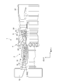
- FIG. 1 is a schematic configuration diagram of a gas turbine to which a turbine blade according to an embodiment is applied.
- a gas turbine 1 is driven to rotate by a combustion gas, a compressor 2 for generating compressed air, a combustor 4 for generating combustion gas using the compressed air and fuel, and the combustion gas.
- a turbine 6 configured as described above.
- a generator (not shown) is connected to the turbine 6.
- the compressor 2 includes a plurality of stationary blades 16 fixed to the compressor casing 10 side, and a plurality of moving blades 18 implanted in the rotor 8 so as to be alternately arranged with respect to the stationary blades 16. .
- the air taken in from the air intake 12 is sent to the compressor 2, and this air passes through the plurality of stationary blades 16 and the plurality of moving blades 18 and is compressed so as to be high-temperature and high-pressure. Compressed air.
- Fuel and compressed air generated by the compressor 2 are supplied to the combustor 4.
- the fuel and compressed air are mixed and burned in the combustor 4, and the working fluid of the turbine 6 is mixed. Is generated.
- a plurality of combustors 4 may be arranged in the casing 20 along the circumferential direction around the rotor.
- the turbine 6 has a combustion gas passage 28 formed in the turbine casing 22, and includes a plurality of stationary blades 24 and moving blades 26 provided in the combustion gas passage 28.
- the stationary blades 24 are fixed to the turbine casing 22 side, and a plurality of stationary blades 24 arranged along the circumferential direction of the rotor 8 constitutes a stationary blade row.
- the moving blades 26 are implanted in the rotor 8, and a plurality of moving blades 26 arranged along the circumferential direction of the rotor 8 constitute a moving blade row.
- the stationary blade rows and the moving blade rows are alternately arranged in the axial direction of the rotor 8.
- the combustion gas from the combustor 4 flowing into the combustion gas flow path 28 passes through the plurality of stationary blades 24 and the plurality of moving blades 26, so that the rotor 8 is rotationally driven.
- the generated generator is driven to generate electric power.
- the combustion gas after driving the turbine 6 is discharged to the outside through the exhaust chamber 30.
- At least one of the rotor blades 26 or the stationary blades 24 of the turbine 6 is a turbine blade 40 described below.
- description will be made mainly with reference to the drawings of the moving blade 26 as the turbine blade 40, but basically the same description can be applied to the stationary blade 24 as the turbine blade 40.
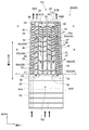
- FIG. 2 is a partial cross-sectional view along the blade height direction of the moving blade 26 (turbine blade 40) according to the embodiment
- FIG. 3 is a view showing a BB cross section of FIG.
- the arrow in a figure shows the direction of the flow of a cooling fluid.
- 4A to 4C are cross-sectional views of the moving blade 26 at three different positions in the blade height direction, respectively
- FIG. 4A is a view showing an AA cross section near the tip 48 of FIG. 4B is a diagram showing a BB cross section near the intermediate region in the blade height direction of FIG. 2 (that is, a view equivalent to FIG. 3)
- FIG. 4C is a CC cross section near the base end 50 of FIG.
- the moving blade 26 that is the turbine blade 40 according to the embodiment includes a blade body 42, a platform 80, and a blade root portion 82.
- the blade root portion 82 is embedded in the rotor 8 (see FIG. 1), and the moving blade 26 rotates together with the rotor 8.
- the platform 80 is configured integrally with the blade root portion 82.
- the wing body 42 is provided so as to extend along the radial direction of the rotor 8 (hereinafter, simply referred to as “radial direction” or “span direction”), and the base end to which the platform 80 is fixed. 50 and a tip 48 made of a top plate 49 that is located on the opposite side (radially outside) of the base end 50 in the blade height direction (radial direction of the rotor 8) and forms the top of the blade body 42. .
- the blade body 42 of the moving blade 26 has a leading edge 44 and a trailing edge 46 from the base end 50 to the tip 48, and the blade surface of the blade 42 has a blade height between the base end 50 and the tip 48. It includes a pressure surface (abdominal surface) 56 in which the blade surface extending along the vertical direction is formed in a concave shape and a suction surface (back surface) 58 in which the blade surface is formed in a convex shape.
- the wing body 42 has two serpentine channels (meandering channels) 61 ⁇ / b> A and 61 ⁇ / b> B as cooling channels and a leading edge than the serpentine channels 61 ⁇ / b> A and 61 ⁇ / b> B.
- a leading edge side passage 36 located on the 44 side is formed.
- the serpentine channels 61A and 61B and the leading edge side passage 36 are supplied with cooling fluid from the outside through the internal channels 84A, 84B and 85, respectively.
- the cooling fluid to the cooling channels such as the serpentine channels 61A and 61B and the leading edge side channel 36, the blades provided in the combustion gas channel 28 of the turbine 6 and exposed to the high-temperature combustion gas.
- the body 42 is convectively cooled from the inner wall surface side of the wing body 42.
- the two serpentine channels include a serpentine channel 61A located on the front edge 44 side and a serpentine channel 61B located on the rear edge 46 side. These serpentine channels 61A and 61B are provided on the wing body 42. It is provided inside and is partitioned by ribs (partition walls) 31 extending along the blade height direction.
- the serpentine channel 61A located on the leading edge side and the leading edge side passage 36 are provided inside the wing body 42 and are partitioned by ribs 29 extending along the blade height direction.
- the two serpentine channels 61A and 61B have a plurality of paths 60 (paths 60a to 60c and 60d to 60f) extending along the blade height direction, respectively.
- each serpentine flow path 61A, 61B are provided inside the wing body 42 and are partitioned by ribs 32 extending along the wing height direction. Further, the adjacent paths 60 in the serpentine channels 61A and 61B are connected to each other on the distal end 48 side or the proximal end 50 side, and the flow direction of the cooling fluid is reversed in the blade height direction at this connection portion.
- a return flow path 33 that is folded back is formed, and the serpentine flow paths 61A and 61B as a whole have a shape meandering in the radial direction. That is, the plurality of paths 60a to 60c and the plurality of paths 60d to 60f communicate with each other via the return flow path 33 to form serpentine flow paths 61A and 61B.
- the serpentine flow path 61A on the leading edge side includes three paths 60a-60c, which pass from the trailing edge 46 side to the leading edge 44 side. They are arranged in this order.
- the serpentine channel 61B on the rear edge side includes three paths 60d to 60f, and these paths 60d to 60f are arranged in this order from the front edge 44 side to the rear edge 46 side.
- the plurality of paths 60 forming the serpentine channels 61A and 61B include a final path 66 located on the most downstream side of the flow of the cooling fluid. That is, in the serpentine channel 61A, the path 60c located closest to the front edge 44 is the final path 66, and in the serpentine channel 61B, the path 60f positioned closest to the rear edge 46 is the final path 66.
- the cooling fluid passes, for example, the most upstream path of the serpentine channels 61A and 61B via the internal channels 84A and 84B formed inside the blade root portion 82. (In the example shown in FIGS. 2 and 3, it is introduced into the path 60a and the path 60d), and sequentially flows through a plurality of paths 60 constituting each of the serpentine channels 61A and 61B toward the downstream side. And the cooling fluid which flows through the last path 66 on the most downstream side in the cooling fluid flow direction among the plurality of paths 60 passes through the outlet openings 64A and 64B provided on the tip 48 side of the blade body 42, and the It flows out to the external combustion gas flow path 28.
- the outlet openings 64A and 64B are openings formed in the top plate 49. At least a portion of the cooling fluid flowing through the final path 66 is discharged from the outlet opening 64B.
- a cooling fluid stagnation space is generated in the space near the top plate 49 of the final path 66, and the inner wall surface of the top plate 49 is suppressed from being overheated. it can.
- the shapes of the serpentine channels 61A and 61B are not limited to the shapes shown in FIGS.
- the number of serpentine channels formed inside the blade body 42 of one turbine blade 40 is not limited to two, and may be one or three or more.
- the serpentine channel may be branched into a plurality of channels at a branch point on the serpentine channel.
- the path located on the most rear edge side is usually the final path of the serpentine flow path.
- leading edge side passage 36 is a cooling passage 59 arranged closest to the leading edge 44, and is a passage having the highest heat load.
- the leading edge side passage 36 communicates with the internal flow path 85 on the base end 50 side, and communicates with the outlet opening 38 formed in the top plate 49 on the distal end 48 side.
- the cooling fluid supplied to the leading edge side passage 36 via the internal passage 85 flows through the leading edge side passage 36 that is a one-way passage from the base end 50 side to the tip end 48 side, and from the outlet opening 38 to the combustion gas passage 28. Discharged.
- the cooling fluid convectively cools the inner wall surface of the leading edge side passage 36 in the process of flowing through the leading edge side passage 36.
- a plurality of cooling holes 70 are arranged in the trailing edge 47 (the portion including the trailing edge 46) of the blade body 42 so as to be arranged along the blade height direction. Is formed.
- the plurality of cooling holes 70 communicate with a cooling flow path (in the illustrated example, a path 60f that is the final path 66 of the serpentine flow path 61B on the trailing edge side) formed in the wing body 42, and An opening is formed in a rear edge end surface 46 a which is a surface of the rear edge portion 47.
- illustration of the cooling hole 70 is omitted.
- a part of the cooling fluid flowing in the cooling flow path passes through the cooling hole 70 communicating with the cooling flow path, and the outside of the turbine blade 40 from the opening of the rear edge end surface 46a of the rear edge portion 47 of the blade body 42. To the combustion gas passage 28. In this way, the cooling fluid passes through the cooling hole 70, so that the trailing edge 47 of the blade body 42 is convectively cooled.
- the blade body 42 of the moving blade 26 has a first end 101 and a second end 102 which are both ends in the blade height direction.
- the first end portion 101 is an end portion on the distal end 48 side of the wing body 42
- the second end portion 102 is an end portion on the proximal end 50 side of the wing body 42. That is, in the moving blade 26, the first end portion 101 is located on the radially outer side of the second end portion 102.
- the blade width in the dorsal belly (back 58-belt 56) direction of the wing body 42 is the first end 101 side (the second end 102 side) (the base end 50 side). It is larger than the tip 48 side). That is, in the wing body 42, the blade width in the dorsoventral direction of the second end portion 102 is larger than that of the first end portion.
- each path 60 and front of the serpentine flow paths 61A and 61B in the dorsal belly direction of the blade body 42 at the second end portion 102 that is, the base end 50 side.
- the passage width D2 of the edge side passage 36 (DL2, Da2, Db2,..., Etc. shown in FIG. 4C; hereinafter, also collectively referred to as “D2”) is the cooling channel at the first end 101 (ie, the tip 48 side). It is larger than the passage width D1 (DL1, Da1, Db1,... Shown in FIG. 4A; hereinafter collectively referred to as “D1”).
- the passage width D (DL, Da, Db..., Etc .; hereinafter collectively referred to as “D”) of the cooling flow path in the dorsoventral direction of the blade body 42 is defined by each passage (each path 60 and the front edge side).
- D the passage width of the cooling flow path in the dorsoventral direction of the blade body 42
- the distance between the inner wall surface 63P measured on the pressure surface 56 side of the blade body 42 (see FIG. 4B) and the inner wall surface 63S on the negative pressure surface 58 side (see FIG. 4B) is measured. It is defined as the maximum value.
- the passage width D of the cooling channel is not a rectangular cross section, but is expressed by the following formula (I) in consideration of a deformed passage shape such as a rhombus cross section, a trapezoid cross section, or a triangular cross section. It may be represented by the equivalent diameter ED shown.
- the equivalent diameter ED corresponds to the passage width D described above.
- ED 4A / L (I)
- ED represents the equivalent diameter
- A represents the passage cross-sectional area
- L represents the wetting length of the passage cross section (the length of the entire circumference of one passage cross section). Therefore, in the following description, the passage width D may be read as the equivalent diameter ED.
- the path 60b that is the third path counted from the front edge 44 side among the plurality of paths (the paths 60 and the front edge side paths 36 of the serpentine channels 61A and 61B) provided in the wing body 42.
- the passage width Db1 on the first end portion 101 side (tip 48 side) and the passage width Db2 on the second end portion 102 side (base end 50 side) satisfy the relationship Db1 ⁇ Db2. The same relationship holds for other passages.
- the passage width D may gradually increase from the first end 101 side toward the second end 102 side in the blade height direction. Moreover, each flow path cross-sectional area of the path
- a rib-like turbulator is provided on at least some of the inner wall surfaces 63 (the inner wall surface 63P on the pressure surface 56 side and / or the inner wall surface 63S on the negative pressure surface 58 side) of the plurality of paths 60 constituting the serpentine channels 61A and 61B. 34 is provided.
- a plurality of turbulators are provided along the blade height direction on the inner wall surface 63P on the pressure surface 56 side and the inner wall surface 63S on the suction surface 58 side of each of the plurality of paths 60. 34 is provided.
- a plurality of turbulators 35 are also provided along the blade height direction on the inner wall surface of the leading edge passage 36. Yes.
- FIGS. 5 and 6 are schematic views for explaining the configuration of the turbulator 34 according to the embodiment, and FIG. 5 is a blade height direction of the turbine blade 40 shown in FIGS. 2 to 4C.
- FIG. 6 is a schematic diagram of a partial cross section along a plane including (the radial direction of the rotor 8) and the dorsal belly direction (substantially the circumferential direction of the rotor 8), and FIG. 6 shows the turbine blade 40 shown in FIGS. 3 is a schematic diagram of a partial cross section along a plane including a blade height direction (a radial direction of the rotor 8) and an axial direction of the rotor 8.
- FIG. 6 is a schematic diagram of a partial cross section along a plane including a blade height direction (a radial direction of the rotor 8) and an axial direction of the rotor 8.
- each turbulator 34 is provided on the inner wall surface 63 of the path 60, and the height of the turbulator 34 with respect to the inner wall surface 63 is e. Further, as shown in FIGS. 5 and 6, in the path 60, the plurality of turbulators 34 are provided at intervals of the pitch P. Further, as shown in FIG. 6, the angle between the cooling fluid flow direction (arrow LF in FIG. 6) and each turbulator 34 in the path 60 (however, an acute angle; hereinafter also referred to as an “inclination angle”). , The inclination angle ⁇ .
- the turbulator 34 When the turbulator 34 is provided in the path 60, when the cooling fluid flows through the path 60, flow disturbance such as vortex generation is promoted in the vicinity of the turbulator 34. That is, the cooling fluid that has passed over the turbulator 34 forms a vortex between adjacent turbulators 34 arranged on the downstream side. As a result, in the vicinity of the intermediate position between the turbulators 34 adjacent to each other in the flow direction of the cooling fluid, the vortex flow forming the turbulent flow of the cooling fluid contacts the inner wall surface 63 of the path 60, and between the cooling fluid and the blade body 42. The heat transfer coefficient can be increased, and the turbine blade 40 can be effectively cooled.
- the thermal load applied to the turbine blades increases, so that the blade width in the dorsoventral direction at the second end portion 102 on the base end 50 side that supports the turbine blades is increased,
- the cooling flow path disposed inside the blade body has the first end portion.
- the channel cross-sectional area of the cooling channel on the part 101 side is small, and the channel cross-sectional area of the cooling channel on the second end 102 side is selected to be large.
- the turbulator 34 is a turbulent flow promoting member for increasing the heat transfer of the inner wall surface of the cooling channel, and an appropriate turbulator height e, pitch P, It is important to select the inclination angle ⁇ to exert the maximum cooling performance for the wing body.
- the effect of improving the heat transfer coefficient by the turbulator 34 varies depending on the height e, the pitch P, the inclination angle ⁇ , and the path width D of the path (passage).
- the generation state of the vortex flow of the cooling fluid changes depending on the inclination angle ⁇ of the turbulator 34 and affects the heat transfer coefficient with the blade inner wall.
- the vortex may not contact the inner wall surface 63. Therefore, an appropriate range exists between the heat transfer coefficient and the inclination angle ⁇ of the turbulator 34 and the ratio (P / e) of the heat transfer coefficient and the pitch P to the height e as described later.
- the pressure loss of the cooling fluid is increased.
- the passage width D of the path (passage) in the dorsoventral direction is too wide as compared with the height e of the turbulator 34, an effect of increasing the heat transfer coefficient due to the vortex cannot be expected, and the heat transfer coefficient is lowered. It may cause a decrease in cooling performance. That is, there is an appropriate height e, pitch P, and inclination angle ⁇ of the turbulator 34 that provides a high heat transfer coefficient in accordance with a change in the shape of the cooling channel.
- the effect of improving the heat transfer coefficient by the turbulator 35 (the front edge turbulator 35) provided in the front edge side passage 36 is the same as in the case of the turbulator 34 described above. It changes according to the passage width of the leading edge side passage 36 in the direction.
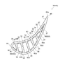
- FIG. 9 is a schematic cross-sectional view of a stationary blade 24 (turbine blade 40) according to an embodiment.
- the arrows in the figure indicate the flow direction of the cooling fluid LF.
- a stationary blade 24 (turbine blade 40) according to an embodiment is provided with respect to a blade body 42, an inner shroud 86 positioned radially inward with respect to the blade body 42, and the blade body 42.
- An outer shroud 88 positioned radially outward.
- the outer shroud 88 is supported by the turbine casing 22 (see FIG. 1), and the stationary blades 24 are supported by the turbine casing 22 via the outer shroud 88.
- the wing body 42 has an outer end 52 located on the outer shroud 88 side (ie, radially outer side) and an inner end 54 located on the inner shroud 86 side (ie, radially inner side).
- the wing body 42 of the stationary blade 24 has a leading edge 44 and a trailing edge 46 from the outer end 52 to the inner end 54, and the blade surface of the wing body 42 has a blade height between the outer end 52 and the inner end 54.
- a pressure surface (abdominal surface) 56 and a suction surface (back surface) 58 extending along the vertical direction are included.
- a serpentine flow path 61 formed by a plurality of paths 60 is formed inside the blade body 42 of the stationary blade 24.
- a serpentine channel 61 is formed by five paths 60a to 60e.
- the paths 60a to 60e are arranged in this order from the front edge 44 side to the rear edge 46 side.
- the cooling fluid is introduced into the serpentine flow passage 61 through an internal flow passage (not shown) formed inside the outer shroud 88, and passes through a plurality of paths 60. It flows in order toward the downstream side. And the cooling fluid which flows through the last path 66 (path 60e) on the most downstream side in the flow direction of the cooling fluid among the plurality of paths 60 is provided on the inner end 54 side (the inner shroud 86 side) of the wing body 42. It flows out into the combustion gas flow path 28 outside the stationary blade 24 (turbine blade 40) through the outlet opening 64 or is discharged into the combustion gas from the cooling hole 70 of the trailing edge portion 47 described later. Yes.
- the turbulator 34 described above is provided on at least some of the inner wall surfaces of the plurality of paths 60.
- a plurality of turbulators 34 are provided on the inner wall surface of each of the plurality of paths 60.
- a plurality of cooling holes 70 may be formed in the trailing edge portion 47 of the blade body 42 so as to be arranged along the blade height direction.
- the blade body 42 of the stationary blade 24 has a first end 101 and a second end 102 which are both ends in the blade height direction.
- the first end portion 101 is an end portion on the inner end 54 side of the wing body 42
- the second end portion 102 is an end portion on the outer end 52 side of the wing body 42. That is, in the stationary blade 24, the first end portion 101 is located on the radially inner side of the second end portion 102.
- the vane width of the blade body 42 in the stationary blade 24 is larger at the outer end 52 side (second end 102 side) than at the inner end 54 side (first end 101 side). It has become. That is, in the wing body 42, the blade width of the second end portion 102 is larger than that of the first end portion 101.
- the passage width D of the path 60 is the serpentine flow in the dorsoventral direction of the blade body 42 at the second end portion 102 (that is, the outer end 52 side), as in the case of the moving blade 26 described above.
- the passage width D2 of each path 60 of the passage 61 is larger than the passage width D1 at the first end portion 101 (that is, the inner end 54 side).
- the passage width D may gradually increase from the first end 101 side toward the second end 102 side in the blade height direction.
- pass 60 may increase as it approaches the said 2nd end part from the said 1st end part in a blade
- the concept of the equivalent diameter ED described above can also be applied to the passage width D of the stationary blade 24.
- the height of the plurality of turbulators 34 provided in the cooling passage 59 that is at least one of the paths 60a to 60f is the blade height.
- the first end 101 side the tip 48 side of the moving blade 26, the inner end 54 side of the stationary blade 24
- the second end 102 the base end 50 side of the moving blade 26, the outer end 52 side of the stationary blade 24.
- the height e of the turbulator 34 increases as the passage width D of the cooling passage 59 increases from the first end 101 side toward the second end 102 side.
- the height e of the turbulator 34 (of the cooling passage 59).
- the height with respect to the inner wall surface 63 becomes higher.
- the height of the plurality of turbulators 34 may gradually change for each turbulator 34 in the blade height direction. That is, of any two turbulators 34 having different blade height direction positions, the height e of one turbulator 34 closer to the second end 102 is equal to the other turbulator 34 (that is, closer to the first end 101).
- the height e of each of the plurality of turbulators 34 provided in the cooling passage 59 may be set so as to be higher than the height of the other turbulator 34).
- the height of the plurality of turbulators 34 may be changed stepwise for each region in the blade height direction. That is, the cooling passage 59 is divided into a plurality of regions in the blade height direction so that the turbulators 34 belonging to each blade height direction region have the same height e and are closer to the second end portion 102.
- the turbulators 34 belonging to the blade height direction region have a height e higher than the turbulators 34 belonging to the blade height direction region closer to the first end 101 than the height e.
- Each height e may be set.
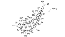
- FIG. 8 is a view showing a cross section of one of the cooling passages 59 constituting the serpentine channel 61 (here, the path 60b of the serpentine channel 61A of the moving blade 26).
- the exemplary cooling passage 59 shown in FIG. 8 is divided into three regions in the blade height direction.
- the plurality of turbulators 34 provided in the cooling passage 59 include the turbulator 34a belonging to the region closest to the first end 101 (the region on the tip 48 side) among the three regions described above, and the second end most. It includes a turbulator 34c belonging to a region close to the portion 102 (region on the base end 50 side) and a turbulator 34b belonging to a region between these two (intermediate region).
- the typical passage width DDc in the dorsoventral direction of the cooling passage 59 at the position of the turbulator 34c belonging to the region on the base end 50 side satisfies the relationship Da ⁇ Db ⁇ Dc.
- the typical passage width D in the dorsoventral direction of the cooling passage 59 in each region is the average value of the passage width D of the cooling passage 59 in the blade height direction position of each turbulator 34 belonging to the region. May be.
- the plurality of turbulators 34a, 34b, 34c belonging to the regions in the blade height direction have the same height, and the height ea of the turbulator 34a belonging to the region on the tip 48 side and the turbulators 34b belonging to the intermediate region.
- the height eb and the height ec of the turbulator 34c belonging to the region on the base end 50 side satisfy the relationship ea ⁇ eb ⁇ ec.
- the height e of the plurality of turbulators 34 provided in the cooling passage 59 may be changed stepwise for each region in the blade height direction.
- the final path 66 in FIG. 7 among the paths 60a to 60f constituting the serpentine flow path 61.
- the plurality of turbulators 34 change stepwise for each region in the blade height direction, as in the example of FIG. .
- the cooling passage 59 is divided into three regions in the blade height direction, and the height of the turbulator 34 is changed in three stages, but in other examples (others In the cooling passage 59), the cooling passage 59 is divided into n regions in the blade height direction, and the height of the turbulator 34 may be changed in n stages (where n is an integer of 2 or more).
- the paths 60a to 60e (cooling passages) in the moving blade 26 shown in FIG. 7 and the paths 60a to 60d (cooling passages) in the stationary blade 24 shown in FIG. n is divided into regions of 2 to 5), and the height of the turbulator 34 changes in n stages in the blade height direction.
- the heat transfer coefficient between the cooling fluid and the turbine blade 40 is improved as compared with the case where the inner wall surface 63 is a smooth surface without the turbulator 34.
- the passage width D of the cooling passage 59 changes in the blade height direction, if the height e of the turbulator 34 is constant and the same height, the passage width D of the cooling passage 59 is relatively wide. At the position in the direction, the effect of improving the heat transfer rate is reduced compared to the position in the blade height direction where the passage width D of the cooling passage 59 is relatively narrow.
- the height e of the turbulator 34 is selected so that the heat transfer coefficient on the blade surface is maintained even if the passage width D of the cooling passage 59 changes in the blade height direction. Is desirable. As the passage width D of the cooling passage 59 approaches the second end portion 102 where the passage width D of the cooling passage 59 is relatively large from the first end portion 101 where the passage width D of the cooling passage 59 is relatively small in the blade height direction, the heat transfer coefficient on the blade surface is maintained. As described above, the height of the turbulator 34 was increased.
- the turbulator height e on the first end 101 side with a small passage width D compared to the second end 102 side with a large passage width D is higher than the appropriate height because of the pressure loss of the cooling fluid. Undesirable in terms of increase.
- the passage width D of the cooling passage 59 is reduced and the height e of the turbulator 34 is set low on the first end 101 side in the blade height direction.
- the passage width D of the cooling passage 59 is relatively narrow, so that the pressure loss tends to increase. An increase in pressure loss can be suppressed. Therefore, according to the above-described embodiment, the turbine blade 40 whose passage width D of the cooling passage 59 changes in the blade height direction can be efficiently cooled.
- the height e of any one turbulator 34 and the blade height of the turbulator 34 are set.
- the average (e / D) AVE of the ratios (e / D) for all turbulators 34) satisfies the relationship 0.5 ⁇ (e / D) / (e / D) AVE ⁇ 2.0.
- (e / D) and (e / D) AVE described above satisfy 0.9 ⁇ (e / D) / (e / D) AVE ⁇ 1.1. Also good.
- (e / D) and (e / D) AVE described above are (D1 / D2) ⁇ (e / D) / (e / D) AVE ⁇ (D2 / D1) May be satisfied.
- D1 is the passage width of the cooling passage 59 at the position of the turbulator 34 located closest to the first end 101 in the blade height direction among the plurality of turbulators 34.
- D2 is the passage width of the cooling passage 59 at the position of the turbulator 34 located closest to the second end 102 in the blade height direction. Note that the relationship of the above relational expression may be established for each (all) of the plurality of turbulators 34 provided in the cooling passage 59 described above.
- (e / D) related to an arbitrary turbulator 34 among the plurality of turbulators 34 provided in the cooling passage 59 is the (e / D) of all the plurality of turbulators provided in the cooling passage. It is set to be a value close to (e / D) AVE , which is an average of Alternatively, the change in (e / D) is set to be smaller than the change in the passage width D of the cooling passage from the first end 101 toward the second end 102 in the blade height direction. Accordingly, it is possible to suppress an extreme decrease in heat transfer coefficient and an extreme increase in pressure loss in the blade height direction, and effectively cool the turbine blade 40 while suppressing the uneven distribution of metal temperature on the blade wall. can do.
- the turbulator 34 positioned closest to the first end 101 in the blade height direction.
- the passage width D of the cooling passage 59 at the position of D is D1
- the passage width D of the cooling passage 59 at the position of the turbulator 34 located closest to the second end 102 in the blade height direction is D2
- the passage width The ratio (D2 / D1) between D1 and the passage width D2 satisfies the relationship of 1.5 ⁇ (D2 / D1).
- the passage width D1 and the passage width D2 may satisfy a relationship of 2.0 ⁇ (D2 / D1).
- the passage width D1 and the passage width D2 may satisfy a relationship of 2.5 ⁇ (D2 / D1).
- the passage width D2 of the cooling passage 59 on the second end portion 102 side is significantly larger than the passage width D1 of the cooling passage 59 on the first end portion 101 side. Since the height of the turbulator 34 is increased at a position in the blade height direction on the second end 102 side where the passage width D is large, the turbine blade 40 in which the passage width D of the cooling passage 59 changes in the blade height direction. Can be efficiently cooled.
- a pair of turbulators 34 adjacent in the blade height direction in the blade height direction is provided among the plurality of turbulators 34 provided in the cooling passage 59 (at least one of the paths 60a to 60f).
- the pitch P increases as it approaches the second end 102 from the first end 101 in the blade height direction.
- the effect of improving the heat transfer coefficient by the turbulator 34 changes according to the pitch P between the adjacent turbulators 34 in the blade height direction, and the ratio of the pitch P to the height e of the turbulator 34 that provides a high heat transfer coefficient (P / E) exists.
- P / E the ratio of the pitch P to the height e of the turbulator 34 that provides a high heat transfer coefficient
- the pitch P in the blade height direction of a pair of turbulators 34 adjacent in the blade height direction gradually changes for each pair of turbulators 34 in the blade height direction. Also good. That is, the pitch P of one pair of turbulators 34 that is closer to the second end 102 out of any two pairs of turbulators 34 having different positions in the blade height direction is the other pair of turbulators 34 (that is, the first turbulator 34).
- the pitch P of each of the plurality of turbulators 34 provided in the cooling passage 59 may be set to be larger than the pitch P of the pair of turbulators 34) closer to the one end 101.
- the pitch P in the blade height direction of a pair of turbulators 34 adjacent in the blade height direction may be changed stepwise for each region in the blade height direction. That is, the cooling passage 59 is divided into a plurality of regions in the blade height direction so that the plurality of turbulators 34 belonging to the regions in the blade height direction have the same pitch P, and the second end portion The cooling is performed such that the pitch P of the plurality of turbulators 34 belonging to the blade height direction region closer to 102 is larger than the pitch P of the turbulators 34 belonging to the blade height direction region closer to the first end 101.
- the pitch P of each of the plurality of turbulators 34 provided in the passage 59 may be set.
- the exemplary cooling passage 59 shown in FIG. 8 is divided into three regions in the blade height direction as described above, and the plurality of turbulators 34 provided in the cooling passage 59 are the most first.
- the pitch Pa of the plurality of turbulators 34a belonging to the region on the distal end 48 side, the pitch Pb of the plurality of turbulators 34b belonging to the intermediate region, and the pitch Pb of the plurality of turbulators 34c belonging to the region on the proximal end 50 side are Pa ⁇ Pb ⁇ Satisfying the relationship of Pc.
- the pitch P of the plurality of turbulators 34 provided in the cooling passage 59 may change stepwise for each region in the blade height direction. That is, in a certain cooling passage 59, the cooling passage 59 may be divided into n regions in the blade height direction, and the pitch P of the turbulator 34 may be changed in n stages (where n is 2 or more). Integer).
- the ratio (P / ea) of the height of the pair of turbulators 34 to the average ea (P / ea) and the average (P / ea) of the ratios (P / ea) AVE for a plurality of turbulators 34 is 0.5 ⁇ (P / ea) / (P / ea) AVE ⁇ 2.0.
- (P / ea) and (P / ea) AVE described above satisfy 0.9 ⁇ (P / ea) / (P / ea) AVE ⁇ 1.1. Also good.
- (P / ea) relating to an arbitrary pair of turbulators 34 among the plurality of turbulators 34 provided in the cooling passage 59 is the plurality of turbulators 34 provided in the cooling passage 59 (all turbulators). 34), which is an average of (P / ea) AVE , which is an average of (P / ea). Therefore, as it approaches the second end 102 from the first end 101 in the blade height direction, that is, As the height e of the turbulator 34 increases, the pitch P between adjacent turbulators 34 tends to increase. Therefore, by appropriately setting (P / ea) or (P / ea) AVE , a high heat transfer coefficient can be obtained in the blade height direction range in which the turbulator 34 is provided in the cooling passage 59.
- the average ⁇ AVE of the inclination angles ⁇ for all the turbulators satisfies the relationship of 0.5 ⁇ ⁇ / ⁇ AVE ⁇ 2.0.
- the effect of improving the heat transfer coefficient by the turbulator 34 changes according to the inclination angle ⁇ of the turbulator 34 with respect to the flow direction of the cooling fluid in the cooling passage 59, and there is an inclination angle of the turbulator 34 that provides a high heat transfer coefficient.
- the inclination angle ⁇ of the turbulator 34 is substantially constant in the blade height direction, in the range of the blade height where the turbulator 34 is provided in the cooling passage 59. A high heat transfer coefficient can be obtained.
- the cooling passage 59 described above includes the final path (the path 60f (see FIG. 7) in the moving blade 26) and the path in the stationary blade 24 among the plurality of paths 60a to 60f constituting the serpentine flow path 61. 60e (see FIG. 9)).
- the final path the path 60f (see FIG. 7) in the moving blade 26) and the path in the stationary blade 24 among the plurality of paths 60a to 60f constituting the serpentine flow path 61. 60e (see FIG. 9)).
- a final pasturator 37 is provided.
- the height of the turbulator 34 or the final past turbulator 37 is set to e, and the passage width in the dorsoventral direction of the cooling passage 59 or the final pass 66 at the blade height direction position of the turbulator 34 or the final past turbulator 37 is D. Then, the relationship of the following formula (II) is established. [(E / D) E1 / (e / D) AVE ] ⁇ [(e / D) T_E1 / (e / D) T_AVE ] ... (II) In the above formula (II), (e / D) E1 is the turbulator 34T (see FIGS.
- (E / D) AVE is an average of the ratio (e / D) between the height and the passage width for a plurality of turbulators 34, and (e / D) T_E1 Is the height and the passage width of the final pasturator 37T (see FIGS. 7 and 9) located closest to the first end 101 in the blade height direction among the final pasturators 37.
- (E / D) T_AVE is the average of the ratio (e / D) T of the height and the passage width for a plurality of final pasturators 37.
- the passage of the cooling passage 59 starts from the first end 101 side where the passage width D of the cooling passage 59 is relatively narrow. Since the height e of the turbulator 34 increases as the width D increases toward the second end portion 102, the ratio (e / D) between the height e of the turbulator 34 and the passage width D tends to be nearly constant. (That is, the left side of the relational expression is close to 1). From this, the above relational expression shows that in the final path 66, the passage width D of the final path 66 decreases from the second end 102 side toward the first end 101 side in the blade height direction. It means that the height e of the final pasturator 37 does not decrease as much as the passage width D.
- the height e of the plurality of final path turbulators 37 does not change so much in the blade height direction as compared with the other paths 60. That is, in the final pass 66 in the vicinity of the trailing edge 47, the passage width D of the final pass 66 is narrowed, and it is difficult to select the turbulator height e corresponding to the passage width D of the cooling passage 59 described above. That is, the height e of the final turbulator 37 may be too small with respect to the passage width D of the final path 66, and it may be difficult to process the turbulator.
- the final turbulator 37 having a height e that is relatively larger than the appropriate height e of the turbulator 34 with respect to the passage width D is selected in a range in which the pressure loss of the cooling fluid flowing through the final path 66 is allowed.
- the final turbulator 37 formed in the final path 66 has a height e smaller than that of the turbulators 34 of other paths 60 other than the final path 66, the ratio (e / D) of the height e to the passage width D is It becomes larger than the ratio (e / D) between the height e applied to the other path 60 and the passage width D.
- the ratio (P / e) between the pitch P and the height e of the final turbulator 37 is selected to be constant in the blade height direction. Since the height e of the final turbulator 37 is smaller than that of the other paths 60, the number of final turbulators 37 to be arranged is larger than that of the other paths. Therefore, the final path 66 is compared with the other paths 60 in terms of heat transfer from both the ratio of the height e to the passage width D (e / D) and the ratio of the pitch P to the height e (P / e). The rate is high.
- the flow path cross-sectional area of the final path 66 is reduced from the second end 102 toward the first end 101,
- the flow rate of the cooling fluid can be increased from the path 60.
- the effect of increasing the flow velocity of the cooling fluid flowing through the cooling passage 59, the ratio (e / D) of the height e of the final turbulator 37 to the passage width D, and the number of the final turbulators 37 are set.
- the increase effect acts in a superimposed manner, and a cooling passage 59 having a higher heat transfer coefficient than the other paths 60 is formed. Therefore, the turbine blade 40 can be cooled more effectively by the cooling fluid flowing through the final path 66 having a severe heat load.
- the height e of the final path turbulator 37 provided in the final path 66 is adjacent to the upstream of the final path 66 in the flow direction of the cooling fluid among the plurality of paths 60. It is below the height of the turbulator 34 in the upstream cooling passage that is located and communicates with the final path 66.
- the cooling passage is a path 60e.
- the height of the final path turbulator 37 provided in the final path 66 (path 60f) is equal to or less than the height of the turbulator 34 provided in the path 60e that is the upstream side cooling passage.
- it is located adjacent to the upstream side in the flow direction of the cooling fluid with respect to the final path 66 (pass 60 e) and communicates with the final path 66.
- the upstream cooling passage is a path 60d.
- the height of the final path turbulator 37 provided in the final path 66 (pass 60e) is equal to or less than the height of the turbulator 34 provided in the path 60d that is the upstream side cooling passage.
- the turbulator heights e of the respective paths 60 at the same height in the blade height direction to the tip 48 of the first end 101 are compared with the base end 50 at the second end 102 as a reference.
- the height e of the final turbulator 37 in the final path 66 is selected to be equal to or lower than the height e of the turbulator 34 in the same blade height position in the other path 60 located upstream in the flow direction of the cooling fluid.
- the selection is made to be equal to or less than the height of the turbulator.
- a number of turbulators (final past turbulators 37) can be provided. Thereby, the turbine blade 40 can be more effectively cooled by the cooling fluid flowing through the final path 66.
- the height of the turbulator 34 provided in the cooling passage 59 or the front edge turbulator 35 provided in the leading edge side passage 36 is defined as e, and the height of the turbulator 34 or the leading edge turbulator 35 in the blade height direction is set to e.
- the passage width in the dorsoventral direction of the cooling passage 59 or the leading edge side passage 36 at the position is D, the following formula (III) is established. [(E / D) E2 / (e / D) AVE ]> [(e / D) L_E2 / (e / D) L_AVE ] ...
- (e / D) E2 is the height of the turbulator 34H (see FIG. 7) located closest to the second end 102 in the blade height direction among the plurality of turbulators 34
- (E / D) AVE is an average of the ratio (e / D) of the height e and the passage width D for a plurality of turbulators 34
- (e / D) L_E2 Is the ratio of the height e to the passage width D for the leading edge turbulator 35H located closest to the second end 102 in the blade height direction among the plurality of leading edge turbulators 35
- (e / D) L_AVE is the ratio (e / D) L of the height e to the passage width D for the plurality of leading edge side turbulators 35.
- the turbulator 34 provided in the cooling passage 59 has the second end where the passage width D of the cooling passage 59 is relatively wide from the first end 101 side where the passage width D of the cooling passage 59 is relatively narrow. Since the height e of the turbulator becomes higher toward the part 102 side, the ratio (e / D) between the height e of the turbulator 34 and the passage width D tends to be nearly constant (that is, the left side of the above relational expression) Is close to 1).
- the above-described relational expression indicates that the passage width D of the final path 66 increases from the first end 101 side to the second end 102 side in the blade height direction, whereas the leading edge side turbulator 35
- the height e means that it does not increase as much as the passage width D. That is, according to the above-described embodiment, in the leading edge side passage 36, the height e of the plurality of leading edge turbulators 35 does not change so much in the blade height direction. Therefore, in the leading edge side passage 36 to which a relatively low-temperature cooling fluid is supplied, the effect of improving the heat transfer coefficient by the turbulator (the leading edge turbulator 35) on the second end 102 side located upstream of the flow of the cooling fluid. And the temperature rise of the cooling fluid flowing toward the first end 101 side can be suppressed. Thereby, the turbine blade 40 can be cooled more effectively.
- an expression representing a relative or absolute arrangement such as “in a certain direction”, “along a certain direction”, “parallel”, “orthogonal”, “center”, “concentric” or “coaxial”. Represents not only such an arrangement strictly but also a state of relative displacement with tolerance or an angle or a distance to obtain the same function.
- an expression indicating that things such as “identical”, “equal”, and “homogeneous” are in an equal state not only represents an exactly equal state, but also has a tolerance or a difference that can provide the same function. It also represents the existing state.
- expressions representing shapes such as quadrangular shapes and cylindrical shapes not only represent shapes such as quadrangular shapes and cylindrical shapes in a strict geometric sense, but also within a range where the same effects can be obtained.
- a shape including an uneven portion or a chamfered portion is also expressed.
- the expression “comprising”, “including”, or “having” one constituent element is not an exclusive expression for excluding the existence of another constituent element.
Landscapes
- Engineering & Computer Science (AREA)
- Mechanical Engineering (AREA)
- General Engineering & Computer Science (AREA)
- Chemical & Material Sciences (AREA)
- Combustion & Propulsion (AREA)
- Turbine Rotor Nozzle Sealing (AREA)
Priority Applications (5)
| Application Number | Priority Date | Filing Date | Title |
|---|---|---|---|
| MX2020010640A MX2020010640A (es) | 2018-04-17 | 2019-04-12 | Alabe para turbina y turbina de gas. |
| US17/043,869 US11242759B2 (en) | 2018-04-17 | 2019-04-12 | Turbine blade and gas turbine |
| DE112019000898.6T DE112019000898B4 (de) | 2018-04-17 | 2019-04-12 | Turbinenschaufel und gasturbine |
| KR1020207026189A KR102467118B1 (ko) | 2018-04-17 | 2019-04-12 | 터빈 날개 및 가스 터빈 |
| CN201980018488.1A CN111868352A (zh) | 2018-04-17 | 2019-04-12 | 涡轮叶片及燃气轮机 |
Applications Claiming Priority (2)
| Application Number | Priority Date | Filing Date | Title |
|---|---|---|---|
| JP2018-078907 | 2018-04-17 | ||
| JP2018078907A JP7096695B2 (ja) | 2018-04-17 | 2018-04-17 | タービン翼及びガスタービン |
Publications (1)
| Publication Number | Publication Date |
|---|---|
| WO2019203158A1 true WO2019203158A1 (ja) | 2019-10-24 |
Family
ID=68240175
Family Applications (1)
| Application Number | Title | Priority Date | Filing Date |
|---|---|---|---|
| PCT/JP2019/015994 Ceased WO2019203158A1 (ja) | 2018-04-17 | 2019-04-12 | タービン翼及びガスタービン |
Country Status (8)
| Country | Link |
|---|---|
| US (1) | US11242759B2 (https=) |
| JP (1) | JP7096695B2 (https=) |
| KR (1) | KR102467118B1 (https=) |
| CN (1) | CN111868352A (https=) |
| DE (1) | DE112019000898B4 (https=) |
| MX (1) | MX2020010640A (https=) |
| TW (1) | TWI710696B (https=) |
| WO (1) | WO2019203158A1 (https=) |
Families Citing this family (4)
| Publication number | Priority date | Publication date | Assignee | Title |
|---|---|---|---|---|
| US11629601B2 (en) * | 2020-03-31 | 2023-04-18 | General Electric Company | Turbomachine rotor blade with a cooling circuit having an offset rib |
| CN113586165B (zh) * | 2021-07-20 | 2022-09-16 | 西安交通大学 | 一种具有单一煤油冷却通道的涡轮叶片 |
| CN114087027B (zh) * | 2021-11-23 | 2024-02-27 | 浙江燃创透平机械有限公司 | 一种具有导流管的燃气轮机静叶 |
| JP7847031B2 (ja) * | 2022-05-06 | 2026-04-16 | 三菱重工業株式会社 | タービン翼及びガスタービン |
Citations (4)
| Publication number | Priority date | Publication date | Assignee | Title |
|---|---|---|---|---|
| JPS55107005A (en) * | 1979-02-13 | 1980-08-16 | United Technologies Corp | Turbine blade |
| US5695320A (en) * | 1991-12-17 | 1997-12-09 | General Electric Company | Turbine blade having auxiliary turbulators |
| JP2003193805A (ja) * | 2001-12-11 | 2003-07-09 | United Technol Corp <Utc> | 産業用ガスタービンエンジン用の冷却可能なロータブレード |
| US20080170945A1 (en) * | 2007-01-11 | 2008-07-17 | Rolls-Royce Plc | Aerofoil configuration |
Family Cites Families (22)
| Publication number | Priority date | Publication date | Assignee | Title |
|---|---|---|---|---|
| US4180373A (en) * | 1977-12-28 | 1979-12-25 | United Technologies Corporation | Turbine blade |
| US4278400A (en) * | 1978-09-05 | 1981-07-14 | United Technologies Corporation | Coolable rotor blade |
| US5232343A (en) * | 1984-05-24 | 1993-08-03 | General Electric Company | Turbine blade |
| JPS61205301A (ja) * | 1985-03-06 | 1986-09-11 | Hitachi Ltd | ガスタ−ビン翼 |
| US5700132A (en) * | 1991-12-17 | 1997-12-23 | General Electric Company | Turbine blade having opposing wall turbulators |
| US5681144A (en) * | 1991-12-17 | 1997-10-28 | General Electric Company | Turbine blade having offset turbulators |
| US5695321A (en) * | 1991-12-17 | 1997-12-09 | General Electric Company | Turbine blade having variable configuration turbulators |
| US5738493A (en) | 1997-01-03 | 1998-04-14 | General Electric Company | Turbulator configuration for cooling passages of an airfoil in a gas turbine engine |
| JP3411775B2 (ja) * | 1997-03-10 | 2003-06-03 | 三菱重工業株式会社 | ガスタービン動翼 |
| JPH10280905A (ja) * | 1997-04-02 | 1998-10-20 | Mitsubishi Heavy Ind Ltd | ガスタービン冷却翼のタービュレータ |
| JPH11241602A (ja) * | 1998-02-26 | 1999-09-07 | Toshiba Corp | ガスタービン翼 |
| EP0945595A3 (en) * | 1998-03-26 | 2001-10-10 | Mitsubishi Heavy Industries, Ltd. | Gas turbine cooled blade |
| EP1022435B1 (en) * | 1999-01-25 | 2009-06-03 | General Electric Company | Internal cooling circuit for a gas turbine bucket |
| US6988872B2 (en) | 2003-01-27 | 2006-01-24 | Mitsubishi Heavy Industries, Ltd. | Turbine moving blade and gas turbine |
| EP1921268A1 (de) * | 2006-11-08 | 2008-05-14 | Siemens Aktiengesellschaft | Turbinenschaufel |
| US7967567B2 (en) * | 2007-03-27 | 2011-06-28 | Siemens Energy, Inc. | Multi-pass cooling for turbine airfoils |
| EP2025869B1 (en) * | 2007-08-08 | 2010-12-15 | Alstom Technology Ltd | Gas turbine blade with internal cooling structure |
| ES2442873T3 (es) * | 2008-03-31 | 2014-02-14 | Alstom Technology Ltd | Perfil aerodinámico de turbina de gas |
| US8840371B2 (en) * | 2011-10-07 | 2014-09-23 | General Electric Company | Methods and systems for use in regulating a temperature of components |
| JP6108982B2 (ja) | 2013-06-28 | 2017-04-05 | 三菱重工業株式会社 | タービン翼及びこれを備える回転機械 |
| CN106536858B (zh) * | 2014-07-24 | 2019-01-01 | 西门子公司 | 具有顺翼展延伸流阻断器的涡轮翼型件冷却系统 |
| US9995146B2 (en) | 2015-04-29 | 2018-06-12 | General Electric Company | Turbine airfoil turbulator arrangement |
-
2018
- 2018-04-17 JP JP2018078907A patent/JP7096695B2/ja active Active
-
2019
- 2019-04-12 DE DE112019000898.6T patent/DE112019000898B4/de active Active
- 2019-04-12 KR KR1020207026189A patent/KR102467118B1/ko active Active
- 2019-04-12 WO PCT/JP2019/015994 patent/WO2019203158A1/ja not_active Ceased
- 2019-04-12 CN CN201980018488.1A patent/CN111868352A/zh active Pending
- 2019-04-12 US US17/043,869 patent/US11242759B2/en active Active
- 2019-04-12 MX MX2020010640A patent/MX2020010640A/es unknown
- 2019-04-16 TW TW108113188A patent/TWI710696B/zh active
Patent Citations (4)
| Publication number | Priority date | Publication date | Assignee | Title |
|---|---|---|---|---|
| JPS55107005A (en) * | 1979-02-13 | 1980-08-16 | United Technologies Corp | Turbine blade |
| US5695320A (en) * | 1991-12-17 | 1997-12-09 | General Electric Company | Turbine blade having auxiliary turbulators |
| JP2003193805A (ja) * | 2001-12-11 | 2003-07-09 | United Technol Corp <Utc> | 産業用ガスタービンエンジン用の冷却可能なロータブレード |
| US20080170945A1 (en) * | 2007-01-11 | 2008-07-17 | Rolls-Royce Plc | Aerofoil configuration |
Also Published As
| Publication number | Publication date |
|---|---|
| US11242759B2 (en) | 2022-02-08 |
| DE112019000898B4 (de) | 2025-04-24 |
| TWI710696B (zh) | 2020-11-21 |
| TW202003999A (zh) | 2020-01-16 |
| CN111868352A (zh) | 2020-10-30 |
| KR20200118859A (ko) | 2020-10-16 |
| KR102467118B1 (ko) | 2022-11-14 |
| JP7096695B2 (ja) | 2022-07-06 |
| US20210025279A1 (en) | 2021-01-28 |
| JP2019183805A (ja) | 2019-10-24 |
| MX2020010640A (es) | 2020-10-28 |
| DE112019000898T5 (de) | 2020-11-05 |
Similar Documents
| Publication | Publication Date | Title |
|---|---|---|
| JP6283462B2 (ja) | タービンエーロフォイル | |
| JP2006077767A (ja) | オフセットされたコリオリタービュレータブレード | |
| WO2019203158A1 (ja) | タービン翼及びガスタービン | |
| JP2006511757A (ja) | 傾斜スキーラ先端を有するタービンブレード | |
| US11339669B2 (en) | Turbine blade and gas turbine | |
| KR102377650B1 (ko) | 에어포일 선행 에지 통로의 후미에서 외벽에 걸쳐 있는 중간 중앙 통로 | |
| CN107366555A (zh) | 叶片以及涡轮转子叶片 | |
| JPH06101406A (ja) | ガスタービン及びガスタービン翼 | |
| JP2019183805A5 (https=) | ||
| US20250369358A1 (en) | Rotor blade and gas turbine provided with same | |
| JPS59231102A (ja) | ガスタ−ビンの翼 | |
| US12270317B2 (en) | Airfoils for gas turbine engines | |
| CN111094701B (zh) | 涡轮叶片及燃气轮机 | |
| JP7224928B2 (ja) | タービン動翼及びガスタービン | |
| JP7847031B2 (ja) | タービン翼及びガスタービン | |
| JP7646030B2 (ja) | タービン翼及びガスタービン | |
| JP7674511B2 (ja) | タービン静翼 | |
| US20200024991A1 (en) | Gas turbine | |
| US20230383661A1 (en) | Turbine stator vane and gas turbine | |
| JP2019085973A5 (https=) | ||
| JPWO2023095721A5 (https=) |
Legal Events
| Date | Code | Title | Description |
|---|---|---|---|
| 121 | Ep: the epo has been informed by wipo that ep was designated in this application |
Ref document number: 19788731 Country of ref document: EP Kind code of ref document: A1 |
|
| ENP | Entry into the national phase |
Ref document number: 20207026189 Country of ref document: KR Kind code of ref document: A |
|
| 122 | Ep: pct application non-entry in european phase |
Ref document number: 19788731 Country of ref document: EP Kind code of ref document: A1 |
|
| WWG | Wipo information: grant in national office |
Ref document number: 112019000898 Country of ref document: DE |