WO2019203018A1 - 鉄道車両用駆動台車 - Google Patents
鉄道車両用駆動台車 Download PDFInfo
- Publication number
- WO2019203018A1 WO2019203018A1 PCT/JP2019/015072 JP2019015072W WO2019203018A1 WO 2019203018 A1 WO2019203018 A1 WO 2019203018A1 JP 2019015072 W JP2019015072 W JP 2019015072W WO 2019203018 A1 WO2019203018 A1 WO 2019203018A1
- Authority
- WO
- WIPO (PCT)
- Prior art keywords
- main motor
- width direction
- vehicle
- vehicle width
- seat
- Prior art date
- Legal status (The legal status is an assumption and is not a legal conclusion. Google has not performed a legal analysis and makes no representation as to the accuracy of the status listed.)
- Ceased
Links
Images

Classifications
-
- B—PERFORMING OPERATIONS; TRANSPORTING
- B61—RAILWAYS
- B61F—RAIL VEHICLE SUSPENSIONS, e.g. UNDERFRAMES, BOGIES OR ARRANGEMENTS OF WHEEL AXLES; RAIL VEHICLES FOR USE ON TRACKS OF DIFFERENT WIDTH; PREVENTING DERAILING OF RAIL VEHICLES; WHEEL GUARDS, OBSTRUCTION REMOVERS OR THE LIKE FOR RAIL VEHICLES
- B61F3/00—Types of bogies
- B61F3/02—Types of bogies with more than one axle
- B61F3/04—Types of bogies with more than one axle with driven axles or wheels
-
- B—PERFORMING OPERATIONS; TRANSPORTING
- B61—RAILWAYS
- B61F—RAIL VEHICLE SUSPENSIONS, e.g. UNDERFRAMES, BOGIES OR ARRANGEMENTS OF WHEEL AXLES; RAIL VEHICLES FOR USE ON TRACKS OF DIFFERENT WIDTH; PREVENTING DERAILING OF RAIL VEHICLES; WHEEL GUARDS, OBSTRUCTION REMOVERS OR THE LIKE FOR RAIL VEHICLES
- B61F5/00—Constructional details of bogies; Connections between bogies and vehicle underframes; Arrangements or devices for adjusting or allowing self-adjustment of wheel axles or bogies when rounding curves
- B61F5/02—Arrangements permitting limited transverse relative movements between vehicle underframe or bolster and bogie; Connections between underframes and bogies
- B61F5/04—Bolster supports or mountings
- B61F5/10—Bolster supports or mountings incorporating fluid springs
-
- B—PERFORMING OPERATIONS; TRANSPORTING
- B61—RAILWAYS
- B61F—RAIL VEHICLE SUSPENSIONS, e.g. UNDERFRAMES, BOGIES OR ARRANGEMENTS OF WHEEL AXLES; RAIL VEHICLES FOR USE ON TRACKS OF DIFFERENT WIDTH; PREVENTING DERAILING OF RAIL VEHICLES; WHEEL GUARDS, OBSTRUCTION REMOVERS OR THE LIKE FOR RAIL VEHICLES
- B61F5/00—Constructional details of bogies; Connections between bogies and vehicle underframes; Arrangements or devices for adjusting or allowing self-adjustment of wheel axles or bogies when rounding curves
- B61F5/26—Mounting or securing axle-boxes in vehicle or bogie underframes
- B61F5/30—Axle-boxes mounted for movement under spring control in vehicle or bogie underframes
- B61F5/301—Axle-boxes mounted for movement under spring control in vehicle or bogie underframes incorporating metal springs
- B61F5/302—Leaf springs
-
- B—PERFORMING OPERATIONS; TRANSPORTING
- B61—RAILWAYS
- B61F—RAIL VEHICLE SUSPENSIONS, e.g. UNDERFRAMES, BOGIES OR ARRANGEMENTS OF WHEEL AXLES; RAIL VEHICLES FOR USE ON TRACKS OF DIFFERENT WIDTH; PREVENTING DERAILING OF RAIL VEHICLES; WHEEL GUARDS, OBSTRUCTION REMOVERS OR THE LIKE FOR RAIL VEHICLES
- B61F5/00—Constructional details of bogies; Connections between bogies and vehicle underframes; Arrangements or devices for adjusting or allowing self-adjustment of wheel axles or bogies when rounding curves
- B61F5/38—Arrangements or devices for adjusting or allowing self- adjustment of wheel axles or bogies when rounding curves, e.g. sliding axles, swinging axles
- B61F5/48—Trailing or leading bogies for locomotives or motor- driven railcars
-
- B—PERFORMING OPERATIONS; TRANSPORTING
- B61—RAILWAYS
- B61F—RAIL VEHICLE SUSPENSIONS, e.g. UNDERFRAMES, BOGIES OR ARRANGEMENTS OF WHEEL AXLES; RAIL VEHICLES FOR USE ON TRACKS OF DIFFERENT WIDTH; PREVENTING DERAILING OF RAIL VEHICLES; WHEEL GUARDS, OBSTRUCTION REMOVERS OR THE LIKE FOR RAIL VEHICLES
- B61F5/00—Constructional details of bogies; Connections between bogies and vehicle underframes; Arrangements or devices for adjusting or allowing self-adjustment of wheel axles or bogies when rounding curves
- B61F5/50—Other details
- B61F5/52—Bogie frames
Definitions
- the present invention relates to a carriage for a railway vehicle and a drive carriage on which a main motor is mounted.
- a main motor seat in which a key groove extending in the vehicle width direction is formed on a lateral beam of the bogie frame is provided, and the main motor is attached to the key groove (see, for example, Patent Document 1). .
- the main motor tries to swing up and down with the keyway as the swing axis due to vibrations during vehicle travel. Since the main motor is heavy, the main motor seat itself and the joint between the main motor seat and the cross beam need to have sufficient strength to withstand the swinging of the main motor. If it does so, there will be a problem of causing an increase in weight and requiring skill in joining work.
- an object of the present invention is to provide a configuration that can relieve the strength requirement of the support structure of the main motor in the drive carriage of a railway vehicle.
- a railcar bogie includes a transverse beam extending in a vehicle width direction, a first main motor supported by a portion of the transverse beam on one side in the longitudinal direction of the vehicle, and the transverse beam on the other side in the longitudinal direction of the vehicle.
- a second main motor supported by the portion, and a connection disposed between the first main motor and the second main motor below the transverse beam and connecting the first main motor and the second main motor to each other A member.
- the connecting member serves as a tension rod that resists the swing, and the first main motor swings and the second main motor swings. Are offset from each other via the connecting member. Accordingly, the strength requirement of the main motor support structure can be relaxed with a simple configuration.
- the strength requirement of the support structure of the main motor in the drive carriage of the railway vehicle can be relaxed.
- the direction in which the railway vehicle travels and the direction in which the vehicle body extends is defined as the vehicle longitudinal direction, and the lateral direction perpendicular thereto is defined as the vehicle width direction.
- the longitudinal direction of the vehicle can also be referred to as the front-rear direction, and the vehicle width direction can also be referred to as the left-right direction.
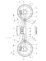
- FIG. 1 is a side view of a railway vehicle carriage 1 according to an embodiment.
- the cart 1 supports the vehicle body 2 from below via an air spring 3 serving as a secondary suspension.
- the carriage 1 includes a carriage frame 4 on which an air spring 3 is mounted.
- the carriage frame 4 includes a horizontal beam 5 extending in the vehicle width direction, but does not include a side beam extending from the vehicle width direction end portion 5a of the horizontal beam 5 in the vehicle longitudinal direction.
- a pair of axles 6 extending along the vehicle width direction are disposed on both sides of the transverse beam 5 in the longitudinal direction of the vehicle.
- Wheels 7 are provided on both sides of the axle 6 in the vehicle width direction.
- Bearings 8 that rotatably support the axle 6 on the outer side of the wheel 7 in the vehicle width direction are provided at both ends of the axle 6 in the vehicle width direction.
- the bearing 8 is accommodated in the axle box 9.
- the vehicle width direction end portion 5 a of the horizontal beam 5 is connected to the axle box 9 by the axle box support device 10.
- the axle box support device 10 includes an axle beam 11 extending from the axle box 9 toward the lateral beam 5 in the longitudinal direction of the vehicle.
- a cylindrical portion 11 a that opens toward both sides in the vehicle width direction is provided at the tip of the shaft beam 11.
- the mandrel 12 is inserted into the cylindrical portion 11a so as to protrude from the cylindrical portion 11a to both sides in the vehicle width direction.
- An elastic bush (not shown) is interposed between the mandrel 12 and the cylindrical portion 11a.
- the bogie frame 4 has receiving beams 14 extending from the vehicle width direction end portion 5 a of the horizontal beam 5 to both sides in the longitudinal direction of the vehicle, and a pair of receiving seats 15 are provided at the tip of the receiving beam 14.
- the pair of receiving seats 15 have insertion grooves 15a recessed downward. Both ends of the mandrel 12 are fitted into the fitting groove 15a from above. Both ends of the mandrel 12 accommodated in the pair of insertion grooves 15a are pressed from above by the lid member 16, and the lid member 16 is fixed to the receiving seat 15 by a fastening member 17 (for example, a bolt).
- the pair of axle boxes 9 separated in the longitudinal direction of the vehicle respectively support the end portions 13b on both sides in the longitudinal direction of the leaf spring 13 extending in the longitudinal direction of the vehicle.
- the central portion 13a in the longitudinal direction of the leaf spring 13 supports the end portion 5a in the vehicle width direction of the cross beam 5 from below.
- the horizontal beam 5 is supported by the axle box 9 via the leaf spring 13. That is, the leaf spring 13 has both a primary suspension function and a conventional side beam function.
- the leaf spring 13 has a bow shape convex downward in a side view.
- a pressing member 18 having an arc-shaped lower surface that protrudes downward is provided at the lower portion of the end 5a in the vehicle width direction of the cross beam 5.
- the pressing member 18 can be placed on the central portion 13a of the leaf spring 13 from above and separated. To touch. That is, the pressing member 18 comes into contact with the upper surface of the leaf spring 13 by the downward load from the cross beam 5 in a state where the leaf spring 13 is not fixed in the vertical direction with respect to the pressing member 18.
- the pressing member 18 is not fixed to the plate spring 13 by the fixture, but maintains a state in which the plate spring 13 is pressed by the pressure of the downward load due to gravity from the lateral beam 5 and the reaction force of the plate spring 13 against the downward load. Be drunk. Accordingly, the leaf spring 13 can swing while changing the pressing area with respect to the lower surface of the pressing member 18.
- a support member 19 is attached to the upper end portion of the axle box 9, and the end portion 13 b of the leaf spring 13 is supported by the axle box 9 from below through the support member 19.
- the upper surface of the support member 19 is inclined toward the center of the carriage in a side view.
- the end 13 b of the leaf spring 13 is also placed on the support member 19 from above without being fixed to the support member 19 in the vertical direction.
- the support member 19 includes a vibration isolation member 20 (for example, rubber) installed on the axle box 9 and a receiving member 21 that is installed on the vibration isolation member 20 and positioned on the vibration isolation member 20.
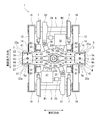
- FIG. 2 is a plan view seen from above the carriage 1 shown in FIG.
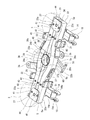
- FIG. 3 is a perspective view seen from above the carriage frame 4 shown in FIG.
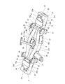
- FIG. 4 is a perspective view of the carriage frame 4 shown in FIG. 2 as viewed from below.
- the cross beam 5 extends in the vehicle width direction, and a center pin arrangement space S is formed in the vehicle width direction central portion 5b (FIGS. 3 and 4).
- the cross beam 5 is made of metal, for example.
- the cross beam 5 includes a pair of pipe members 22 and 23, a pair of intermediate members 24 and 25, a center pin housing member 26, an air spring seat 27, and a pressing member 18.
- the pair of pipe members 22 and 23 extend in the vehicle width direction and are spaced apart from each other in the vehicle longitudinal direction.
- the pipe members 22 and 23 are, for example, square pipes.
- the pipe members 22 and 23 are sealed in order to use the internal space as an auxiliary air chamber for the air spring 3.
- the pipe members 22, 23 are positioned at the vehicle width direction end portion 5 a of the cross beam 5 and linearly extend in the vehicle width direction, and a pair of pipe members 22, 23 a are positioned at the vehicle width direction center portion 5 b of the cross beam 5.
- curved portions 22b and 23b protruding outward in the longitudinal direction of the vehicle so that the distance between the pipe members 22 and 23 increases.
- a center pin arrangement space S is provided in a space formed between the curved portions 22b and 23b of the pair of pipe members 22 and 23. Therefore, the vehicle width direction end portion 5a of the cross beam 5 has a vehicle longitudinal direction dimension smaller than the vehicle width direction center portion 5b of the cross beam 5. In addition, when not using the internal space of the pipe members 22 and 23 as an auxiliary air chamber, it is not necessary to seal the inside.
- the pair of intermediate members 24 and 25 are arranged separately on both sides in the vehicle width direction of the center pin arrangement space S and extend in the vehicle width direction.
- the intermediate members 24 and 25 are sandwiched between the straight portions 22 a and 23 a of the pair of pipe members 22 and 23.
- the pair of intermediate members 24 and 25 are separated from each other in the vehicle width direction and form a gap at the center of the cross beam 5.
- the intermediate members 24 and 25 are, for example, square pipes.
- the intermediate members 24 and 25 are sealed in order to use the internal space as an auxiliary air chamber for the air spring 3.
- the vertical dimension of the intermediate members 24 and 25 is the same as the vertical dimension of the pipe members 22 and 23, for example.
- the vehicle longitudinal direction dimension of the intermediate members 24 and 25 is smaller than the vehicle longitudinal direction dimension of the pipe members 22 and 23, for example.
- the center pin housing member 26 is disposed between the curved portions 22b and 23b of the pair of tube members 22 and 23 and between the pair of intermediate members 24 and 25.
- the center pin housing member 26 includes a cylindrical portion 26a that forms the center pin arrangement space S, a pair of vertical mounting portions 26b that protrude from the cylindrical portion 26a to both sides in the vehicle longitudinal direction, and both sides in the vehicle width direction from the cylindrical portion 26a. And a pair of lateral mounting portions 26c projecting from each other.
- the internal space of the cylindrical portion 26a is open to both sides in the vertical direction, and serves as the center pin arrangement space S.
- a cylindrical elastic bush 29 is fitted into the cylindrical portion 26 a, and a center pin 30 protruding downward from the vehicle body 2 is inserted into the elastic bush 29.
- the vertical mounting portion 26b is joined to the arc-shaped inner surface of the curved portions 22b and 23b of the pipe members 22 and 23 on the center side of the transverse beam 5.
- the joint end (tip) on the vehicle longitudinal direction outer side of the longitudinal attachment portion 26b has an arc shape in plan view, and is joined to the inner side surface of the curved portions 22b and 23b on the center side of the transverse beam 5 by circumferential welding.
- the vertical attachment portion 26b has, for example, a shape in which the joint end side gradually expands. Thereby, the transmission of the traction force in the vehicle longitudinal direction between the pair of tube members 22 and 23 and the center pin 30 is smoothly performed via the center pin housing member 26.
- the vertical dimension of the joint end of the vertical mounting part 26b is smaller than the vertical dimension of the inner surface of the curved beam 22b, 23b on the center side of the transverse beam 5.
- a welded portion W1 that joins the joint end of the vertical mounting portion 26b and the curved portions 22b and 23b is provided on the inner side surface of the curved portions 22b and 23b and is fitted on the inner side surface. Therefore, the welded portion W1 can be completed on one side surface of the curved portions 22b and 23b, and the stress generated in the welded portion W1 is suppressed.
- the joint end (tip) of the lateral mounting portion 26c on the outer side in the vehicle width direction is joined to the end of the intermediate members 24, 25 on the center side of the lateral beam 5 by welding.
- the joining end of the lateral attachment portion 26c has the same shape as the edge of the intermediate members 24 and 25 that faces the lateral attachment portion 26c.
- the joint ends of the lateral attachment portions 26c are joined to the end edges of the intermediate members 24 and 25 by circumferential welding.
- center pin accommodating member 26 has the cylindrical part 26a, the vertical attachment part 26b, and the horizontal attachment part 26c, it is not restricted to this structure.
- the lateral mounting portion 26c may be eliminated, and the intermediate members 24 and 25 may be directly joined to the tubular portion 26a, and various modifications can be applied.
- the air spring seat 27 is provided on the upper surfaces of the pair of pipe members 22 and 23 and the intermediate members 24 and 25 at the vehicle width direction end portion 5a of the cross beam 5.
- the air spring seat 27 is plate-shaped.
- the pressing member 18 is provided on the lower surfaces of the pair of pipe members 22 and 23 and the intermediate members 24 and 25 at the vehicle width direction end portion 5 a of the cross beam 5.
- the pair of tube members 22 and 23 and the intermediate members 24 and 25 are fixed to each other via the air spring seat 27 and the pressing member 18.
- the pressing member 18 includes a pressing portion 18a formed with an arc-shaped lower surface when viewed from the vehicle width direction, and plate-shaped mounting portions 18b provided on both sides of the pressing portion 18a in the vehicle width direction.
- the air spring seat 27 is provided at the vehicle width direction end portion 5a of the cross beam 5.
- the air spring seat 27 is not limited to the end portion and can be installed at a desired position in the vehicle width direction according to the vehicle type.
- the pressing member 18 is fixed to the pipe members 22 and 23 and the intermediate members 24 and 25 at the mounting portion 18b. According to this, the pressing member 18 that transmits the downward load from the transverse beam 5 to the leaf spring 13 serves to connect the pipe members 22 and 23 and the intermediate members 24 and 25 to each other. In addition, since the pressing member 18 is integrated with the cross beam 5, the number of parts is reduced compared to a configuration in which the separate pressing member 18 is engaged with the cross beam 5, and the structure and assembly work of the carriage are simplified. Is done.
- a first brake seat 31 is joined to the straight portion 22 a of the pipe member 22 and a second brake seat 32 is joined to the straight portion 23 a of the pipe member 23 at the vehicle width direction end portion 5 a of the cross beam 5.
- a unit type first tread brake device B ⁇ b> 1 for braking the wheel 7 on one side in the longitudinal direction of the vehicle is fixed to the first brake seat 31, and a unit type is attached to the second brake seat 32.
- the second tread brake device B2 is fixed.
- the first tread brake device B1 and the second tread brake device B2 are independent from each other, and individually brake each of the pair of wheels 7 that are arranged apart in the vehicle longitudinal direction.
- the tread brake devices B ⁇ b> 1 and B ⁇ b> 2 are disposed so as to protrude downward from the cross beam 5.
- the vehicle width direction end portion 5a of the cross beam 5 has a vehicle longitudinal direction dimension smaller than the vehicle width direction central portion 5b of the cross beam 5, so that the work surface space can be easily arranged so that the tread brake devices B1 and B2 can be arranged easily. Is secured.
- the curved portions 22b and 23b are formed in the center portion 5b in the vehicle width direction of the cross beam 5 in the pair of tube members 22 and 23, the separation distance between the pair of pipe members in the center portion 5b in the vehicle width direction of the cross beam 5 On the other hand, the distance between the pair of pipe members at the end in the vehicle width direction of the transverse beam becomes narrow. Therefore, the space for arranging the tread brake devices B1 and B2 can be easily secured by a simple process of bending the pipe members 22 and 23, and the productivity is improved.
- the first gear box G1 and the first main motor M1 are arranged on one side of the transverse beam 5 in the longitudinal direction of the vehicle, and the second gear box G2 and the second main motor M2 are arranged on the other side of the transverse beam 5 in the longitudinal direction of the vehicle.
- the main motors M1 and M2 are connected to gearboxes G1 and G2 via universal joints 33 and 34, respectively, and the first and second gearboxes G1 and G2 are connected to the axle 6. That is, the first gear box G1 and the second gear box G2 are arranged point-symmetrically with respect to the center of the cross beam 5 in a plan view, and the first main motor M1 and the second main motor M2 are arranged with respect to the cross beam 5 in a plan view. They are arranged symmetrically with respect to the center.
- a first gear box receiving seat 35 to which the first gear box G1 is fixed and a second gear box receiving seat 36 to which the second gear box G2 is fixed are joined to the horizontal beam 5 by circumferential welding.
- the first gear box receiving seat 35 is disposed between the apex of the bending portion 22b and the first brake receiving seat 31 in the vehicle width direction
- the second gear box receiving seat 36 is set at the apex of the bending portion 23b in the vehicle width direction.
- the second brake seat 32 are joined to the horizontal beam 5 by circumferential welding.
- the vertical dimension of the joint end facing the curved portions 22b and 23b is smaller than the vertical dimension of the outer surface of the
- the gear box seats 35 and 36 are joined to the outer side surfaces of the curved portions 22b and 23b that are inclined with respect to the vehicle width direction, the gear box seats 35 and 36 extend from the curved portions 22b and 23b in the vehicle longitudinal direction. It projects obliquely outward and outward in the vehicle width direction. According to this configuration, even if the tread brake devices B1 and B2 are arranged close to the gearboxes G1 and G2 in the vehicle width direction, the joint portions of the gearbox seats 35 and 36 with respect to the pipe members 22 and 23 are Since the brake seats 31 and 32 are separated from each other in the vehicle width direction, the welding operation of the gear box seats 35 and 36 to the pipe members 22 and 23 is facilitated.
- the first main motor seat 37 to which the first main motor M1 is fixed and the second main motor seat 38 to which the second main motor M2 is fixed are joined to the horizontal beam 5 by circumferential welding.
- the first main motor seat 37 is disposed between the apex of the curved portion 22b and the first brake seat 31 on the opposite side to the first gear box seat 35 in the vehicle width direction
- the second main motor seat 38 is
- the second gear box receiving seat 36 is disposed between the apex of the curved portion 23b and the second brake receiving seat 32 on the opposite side to the vehicle width direction.
- the vertical dimension of the joint end facing the curved portions 22b and 23b is smaller than the vertical dimension of the outer surface of the curved portions 22b and 23b on the outer side in the vehicle longitudinal direction.
- a welded portion W3 that joins the joint ends of the main motor seats 37 and 38 and the curved portions 22b and 23b is provided on the outer surface of the curved portions 22b and 23b, and fits on the outer surface.
- the receiving beam 14 described above is fixed to the lower surface of the end portion 5a of the lateral beam 5 in the vehicle width direction.
- the receiving beam 14 extends from the vehicle width direction end portion 5a of the horizontal beam 5 to both sides in the vehicle longitudinal direction.
- the receiving beam 14 has a pair of side wall portions 14a spaced apart in the vehicle width direction, and a pressing member 18 is disposed in a space between the pair of side wall portions 14a.
- FIG. 5 is a longitudinal sectional view of the tube member 22 of the carriage frame 4 shown in FIG. 3 as viewed from the longitudinal direction of the vehicle.
- the pipe member 22 is provided with a first projecting member 41 and a second projecting member 42 that project upward and downward from the straight portion 22 a at the vehicle width direction end.
- fitting holes 22e and 22f penetrating in the vertical direction are formed in the upper wall portion of the straight portion 22a of the pipe member 22 at intervals in the vehicle width direction.
- the upper ends of the first projecting member 41 and the second projecting member 42 are fitted into the fitting holes 22e and 22f.
- the outer peripheral surfaces of the first projecting member 41 and the second projecting member 42 are circular from the viewpoint of weldability described later, but may be rectangular.
- the first projecting member 41 and the second projecting member 42 may be hollow or solid.
- the 1st protrusion member 41 and the 2nd protrusion member 42 do not need to penetrate the pipe members 22 and 23, and are good also as a structure fixed to the surface of the pipe members 22 and 23.
- FIG. 1st protrusion member 41 and the 2nd protrusion member 42 do not need to penetrate the pipe members 22 and 23, and are good also as a structure fixed to the surface of the pipe members 22 and 23.
- the air spring seat 27 is formed with a mounting hole 27a having a larger diameter than that of the portion of the first projecting member 41 projecting from the tube member 22 and including the fitting hole 22e when viewed from above. .
- the upper end portion of the first projecting member 41 is inserted through the mounting hole 27a with play.
- the pipe member 22 is circumferentially welded via the mounting hole 27a of the air spring seat 27, and at the same time, the air spring seat 27 is circumferentially welded.
- the upper end portion of the second projecting member 42 is also circumferentially welded to the pipe member 22.
- the air spring seat 27 is fixed to the pipe members 22 and 23 via the first projecting member 41, whereby the pair of pipe members 22 and 23 are connected to each other.
- the welded portion W4 that joins the first projecting member 41 and the air spring seat 27 is formed in a closed loop shape along the outer peripheral surface of the first projecting member 41, and welds that join the second projecting member 42 and the tube member 22.
- the part W5 is also formed in a closed loop shape along the outer peripheral surface of the second projecting member 42.
- Each welded portion is constructed over the projecting member as necessary to ensure the necessary strength as a bogie frame. According to this, since the welded portions W4 and W5 are formed in a closed loop shape without an edge, robot welding is facilitated and manufacturability is improved.
- fitting holes 22g and 22h penetrating in the vertical direction are formed at intervals in the vehicle width direction.
- the lower ends of the first projecting member 41 and the second projecting member 42 are fitted in the fitting holes 22g and 22h.
- the attachment portion 18b of the pressing member 18 has a larger diameter than the outer diameter of the portion of the first projecting member 41 and the second projecting member 42 that projects from the tube member 22, and is fitted into the fitting holes 22g and 22h as viewed from below.
- a mounting hole 18c is formed. The lower ends of the first projecting member 41 and the second projecting member 42 are inserted through the mounting hole 18c with play.
- the lower end portions of the first projecting member 41 and the second projecting member 42 are circumferentially welded to the tube member 22 through the mounting holes 18c of the mounting portion 18b of the pressing member 18, and at the same time, the lower ends of the first projecting member 41 and the second projecting member 42 are also circumferentially mounted on the mounting portion 18b of the pressing member 18. Welded. As described above, the pressing member 18 is fixed to the pipe members 22 and 23 via the first protruding member 41 and the second protruding member 42, whereby the pair of pipe members 22 and 23 are connected to each other.
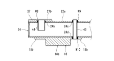
- FIG. 6 is a longitudinal sectional view of the intermediate member 24 of the carriage frame 4 shown in FIG. 3 as viewed from the vehicle longitudinal direction.
- one intermediate member 24 of the pair of intermediate members 24 and 25 is representatively illustrated, but the other intermediate member 25 has the same structure.
- the intermediate member 24 is provided with a third protruding member 43 that protrudes upward and downward from the intermediate member 24 at a position overlapping the pressing member 18 in plan view.
- the intermediate member 24 is provided with a cylindrical body 44 that communicates the internal space of the intermediate member 24 with the air spring 3 at a position overlapping the air spring seat 27.
- fitting holes 24b and 24c penetrating in the vertical direction are formed in the upper wall portion of the intermediate member 24 at intervals in the vehicle width direction.
- the upper ends of the third projecting member 43 and the cylindrical body 44 are fitted in the fitting holes 24b and 24c.
- a fitting hole 24 d into which the third protruding member 43 is fitted is also formed in the lower wall portion of the intermediate member 24.
- the outer peripheral surfaces of the third projecting member 43 and the cylindrical body 44 are circular, but may be rectangular.
- the cylindrical body 44 is required to have a hollow shape and an internal space opened up and down, but the third projecting member 43 may be hollow or solid.
- the third projecting member 43 may not penetrate the intermediate members 24 and 25, and may be configured to be fixed to the surfaces of the intermediate members 24 and 25.
- the number of the protruding members 41 to 44 in the present embodiment is an example, and may be appropriately increased or decreased as necessary.
- the air spring seat 27 is formed with an insertion hole 27b that is larger than the outer diameter of the portion of the cylindrical body 44 protruding upward from the intermediate member 24 and includes the fitting hole 24b when viewed from above. .
- the upper end portion of the cylindrical body 44 is inserted through the insertion hole 27b with play.
- the upper end portion of the cylindrical body 44 is circumferentially welded to the intermediate member 24 through the insertion hole 27 b of the air spring seat 27.
- the welded portion W8 that joins the cylindrical body 44 and the intermediate member 24 may not be joined to the air spring seat 27.
- the welded portions W9 and W10 that join the third projecting member 43 and the intermediate member 24 are the same as the welded portions W5 and W7 that join the second projecting member 42 and the pipe member 22.
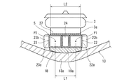
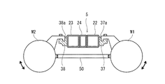
- FIG. 7 is a longitudinal sectional view of the air spring seat 27 and the pressing member 18 of the carriage 1 shown in FIG. 1 viewed from the vehicle width direction.
- the distance between the pipe members 22 and 23 is sufficiently shorter than the vehicle longitudinal direction dimension of the lower end surface 3 a of the air spring 3. That is, at the same vehicle width direction position as the air spring 3, the distance L1 in the vehicle longitudinal direction between the center P1 of the straight portion 22a of the tube member 22 and the center P2 of the straight portion 23a of the tube member 23 is the air spring seat 27. It is shorter than the vehicle longitudinal direction dimension of the lower end surface 3a of the air spring 3 mounted on the vehicle.
- the lower end surface 3a of the air spring 3 overlaps the pipe members 22 and 23 so as to include the centers P1 and P2 in the vehicle longitudinal direction of the end portions in the vehicle width direction of the pipe members 22 and 23 when viewed from above.
- the air spring seat 27 overlaps the pipe members 22 and 23 so as to include the centers P1 and P2 of the end portions in the vehicle width direction of the pipe members 22 and 23 when viewed from above.
- the load transmitted from the air spring 3 to the cross beam 5 via the air spring seat 27 is transmitted to the central portion 13 a of the leaf spring 13 by the pressing member 18.
- the pair of pipe members 22 and 23 are formed with curved portions 22b and 23b at the vehicle width direction center portion 5b of the cross beam 5, the pair of tube members 22 and 23 at the vehicle width direction center portion 5b of the cross beam 5 are formed. While the separation distance is increased, the separation distance between the pair of pipe members 22 and 23 at the vehicle width direction end portion 5a of the cross beam 5 is decreased. Thereby, even if the center pin arrangement space S is formed between the pair of tube members 22 and 23 in the vehicle width direction center portion 5b of the cross beam 5, the tube members 22 and 23 are extended from the lower end surface 3a of the air spring 3 to the vehicle longitudinal direction. It is prevented that it sticks out to the outside in the direction.
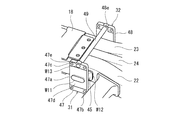
- FIG. 8 is a perspective view illustrating the brake seats 31 and 32 and the connecting member 49 of FIG. 4 as seen from below.
- FIG. 9 is a side view illustrating the brake seats 31 and 32 and the connecting member 49 shown in FIG.
- the first brake seat 31 and the second brake seat 32 are provided with mounting portions 45, 46 that project outward from the transverse beam 5 in the longitudinal direction of the vehicle and vertical directions from the mounting portions 45, 46. Receiving seats 47 and 48 extending in the direction.
- the mounting portion 45 of the first brake seat 31 is joined to the outer surface of the tube member 22 on the vehicle longitudinal direction outer side, and the first tread brake device B1 is fixed to the seat portion 47 of the first brake seat 31.
- the mounting portion 46 of the second brake seat 32 is joined to the outer surface of the tube member 23 in the longitudinal direction of the vehicle, and the second tread brake device B2 is fixed to the seat portion 48 of the second brake seat 32. .
- Through holes 47a are respectively formed in the receiving parts 47 and 48, and the attachment parts 45 and 46 are circumferentially welded to the receiving parts 47 and 48 while being inserted into the through holes 47a. That is, the welding part W11 which joins the attaching parts 45 and 46 inserted through the through hole 47a and the receiving parts 47 and 48 is formed in a closed loop shape along the periphery of the through hole 47a. As described above, the welded portion W11 is formed in a closed loop shape without an edge, thereby facilitating robot welding and improving manufacturability.
- the vertical dimension of the joint ends on the tube members 22 and 23 side of the mounting portions 45 and 46 is smaller than the vertical dimension of the outer surface of the tube members 22 and 23 on the vehicle longitudinal direction outside.
- a welded portion W12 that joins the joining ends of the attachment portions 45 and 46 and the pipe members 22 and 23 is provided on the outer side surface of the pipe members 22 and 23 and fits on the outer side surface.
- a connecting member 49 sandwiched between the receiving portion 47 of the first brake receiving seat 31 and the receiving portion 48 of the second brake receiving seat 32 is disposed below the cross beam 5, a connecting member 49 sandwiched between the receiving portion 47 of the first brake receiving seat 31 and the receiving portion 48 of the second brake receiving seat 32 is disposed.
- the connecting member 49 connects the lower portion of the seat portion 47 of the first brake seat 31 and the lower portion of the seat portion 48 of the second brake seat 32.
- the connecting member 49 is substantially at the center of the axle and extends in a direction orthogonal to the brake support surfaces 47d and 48d of the seats 47 and 48.
- the connecting member 49 has, for example, a rod shape. In the present embodiment, there is one connecting member 49, but a plurality of connecting members 49 may be provided.
- Insertion holes 47e and 48e are formed in the lower part of the receiving parts 47 and 48 of the brake receiving seats 31 and 32, and the ends of the connecting member 49 in the longitudinal direction of the vehicle are inserted into the insertion holes 47e and 48e.
- the seats 47 and 48 are circumferentially welded. That is, a welded portion W13 that joins the end of the connecting member 49 inserted into the insertion holes 47e and 48e and the receiving portions 47 and 48 is formed in a closed loop shape along the periphery of the insertion holes 47e and 48e.
- the connecting member 49 is positioned with respect to the receiving portions 47 and 48 by inserting the connecting member 49 into the insertion holes 47e and 48e, the welding operation of the connecting member 49 to the receiving portions 47 and 48 is performed. Can be easily performed.
- the brake reaction force received by the tread brake devices B1 and B2 from the wheels 7 during braking is transmitted to the seat portions 47 and 48 of the brake seats 31 and 32. It will play the role of a tension rod that resists the reaction force. Therefore, the brake reaction force received by the first brake seat 31 and the brake reaction force received by the second brake seat 32 cancel each other through the connecting member 49, and a strong reinforcing material is applied to the brake seats 31 and 32. It becomes possible to eliminate the necessity of providing.
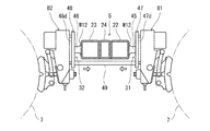
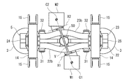
- FIG. 10 is a bottom view for explaining the main motors M1, M2 and the connecting member 50 of the carriage shown in FIG.
- FIG. 11 is a side view illustrating the main motors M1 and M2 and the connecting member 50 shown in FIG.
- a connecting member 50 sandwiched between the first main motor M ⁇ b> 1 and the second main motor M ⁇ b> 2 is disposed below the cross beam 5.
- the connecting member 50 connects the first main motor M1 and the second main motor M2.
- the connecting member 50 has, for example, a substantially I shape, and both ends thereof are fixed to the main motors M1, M2. Although there is one connecting member 50, a plurality of connecting members 50 may be provided.
- the main motor seats 37 and 38 have key grooves 37a and 38a extending along the cross beam 5 for locking the main motors M1 and M2, respectively.
- the main motors M1, M2 are fastened to the main motor seats 37, 38 while being locked in the key grooves 37a, 38a. Since the main motor seats 37 and 38 are joined to the outer surfaces of the curved portions 22b and 23b that are inclined with respect to the vehicle width direction, the key grooves 37a and 38a are inclined with respect to the vehicle width direction.
- the first main motor M1 is attached to the first main motor seat 37 so as to swing with the key groove 37a as the first swing axis X1, and the second main motor M2 has the key groove 38a as the second swing axis.
- the main motor seats 37 and 38 may be arranged so that the swing axis lines X1 and X2 are orthogonal to the virtual line V, and the key grooves 37a and 38a do not necessarily have to be inclined in the vehicle width direction. .
- the swing axis lines X1 and X2 of the first main motor M1 and the second main motor M2 are inclined with respect to the vehicle width direction so that the center side of the carriage is away from the center of the cross beam 5.
- the swing axes X1 and X2 of the first main motor M1 and the second main motor M2 are substantially orthogonal to a virtual line V connecting the center of gravity C1 of the first main motor M1 and the center of gravity C2 of the second main motor M2. is doing.
- the connecting member 50 extends along the virtual line V. When the number of connecting members 50 is one, it is preferable that the connecting member 50 overlaps the virtual line V in plan view.
- the connecting member 50 serves as a tension rod that resists the swing, and the first main motor M1 swings and the second The swing of the main motor M2 is canceled out by the connecting member 50. Therefore, the strength requirement of the support structure for the main motors M1, M2 can be relaxed with a simple configuration. Further, since the swing axes X1 and X2 of the main motors M1 and M2 are substantially orthogonal to the virtual line V in plan view, the loads due to the swings of the main motors M1 and M2 face each other, and the connecting member 50 is twisted. Is suppressed from occurring. Since the connecting member 50 extends along the imaginary line V, it is sufficient to ensure the strength of the connecting member 50 in the tension and compression directions. Therefore, each swing of the main motors M1, M2 can be effectively offset while reducing the weight of the connecting member 50.
- the present invention is not limited to the above-described embodiment, and the configuration can be changed, added, or deleted.
- the cart provided with leaf springs by omitting the side beam of the cart frame is exemplified, but a general cart having side beams extending in the vehicle longitudinal direction from both ends of the lateral beam in the vehicle width direction is adopted. May be.
- the vehicle width direction end 5a of the horizontal beam 5 may be fixed to the side beam by welding or the like.
- the pressing member 18 for pressing the leaf spring 13 is not necessary. Therefore, instead of the pressing member 18, the pipe members 22, 23 and the intermediate members 24, 25 are interconnected on the lower surface side.
- a plate-like member is simply used and fixed to each other via a protruding member in the same manner as the air spring seat 27.
- the bending portion 22b may be formed only on one of the pair of tube members 22 and 23.
- FIG. in the above embodiment, the driving cart is exemplified, but a non-driving cart may be used.
- the structure related to the main motor and the gear box is not necessary, but the structure of the cross beam 5 and the structure of the brake seat can be suitably employed.
Landscapes
- Engineering & Computer Science (AREA)
- Mechanical Engineering (AREA)
- Vehicle Body Suspensions (AREA)
- Vibration Prevention Devices (AREA)
Priority Applications (3)
| Application Number | Priority Date | Filing Date | Title |
|---|---|---|---|
| US17/048,510 US11731669B2 (en) | 2018-04-16 | 2019-04-05 | Railcar driving bogie |
| SG11202010139XA SG11202010139XA (en) | 2018-04-16 | 2019-04-05 | Railcar driving bogie |
| CN201980003078.XA CN110753652B (zh) | 2018-04-16 | 2019-04-05 | 铁道车辆用驱动转向架 |
Applications Claiming Priority (2)
| Application Number | Priority Date | Filing Date | Title |
|---|---|---|---|
| JP2018078185A JP6622842B2 (ja) | 2018-04-16 | 2018-04-16 | 鉄道車両用駆動台車 |
| JP2018-078185 | 2018-04-16 |
Publications (1)
| Publication Number | Publication Date |
|---|---|
| WO2019203018A1 true WO2019203018A1 (ja) | 2019-10-24 |
Family
ID=68239710
Family Applications (1)
| Application Number | Title | Priority Date | Filing Date |
|---|---|---|---|
| PCT/JP2019/015072 Ceased WO2019203018A1 (ja) | 2018-04-16 | 2019-04-05 | 鉄道車両用駆動台車 |
Country Status (6)
| Country | Link |
|---|---|
| US (1) | US11731669B2 (enExample) |
| JP (1) | JP6622842B2 (enExample) |
| CN (1) | CN110753652B (enExample) |
| SG (1) | SG11202010139XA (enExample) |
| TW (1) | TW201943589A (enExample) |
| WO (1) | WO2019203018A1 (enExample) |
Families Citing this family (2)
| Publication number | Priority date | Publication date | Assignee | Title |
|---|---|---|---|---|
| CN110155087B (zh) * | 2019-05-30 | 2021-02-02 | 中车青岛四方机车车辆股份有限公司 | 轨道车辆齿轮箱、轨道车辆转向架以及轨道车辆 |
| CN118877033B (zh) * | 2024-08-29 | 2025-10-31 | 中车青岛四方机车车辆股份有限公司 | 转向架的横梁组成、构架及转向架、轨道车辆 |
Citations (4)
| Publication number | Priority date | Publication date | Assignee | Title |
|---|---|---|---|---|
| JPS5034407Y2 (enExample) * | 1971-09-08 | 1975-10-07 | ||
| JPH0370663B2 (enExample) * | 1983-07-04 | 1991-11-08 | Hitachi Ltd | |
| JPH0353971Y2 (enExample) * | 1984-03-07 | 1991-11-27 | ||
| US20140261061A1 (en) * | 2012-07-10 | 2014-09-18 | Csr Nanjing Puzhen Co., Ltd | Flexible direct drive bogie |
Family Cites Families (12)
| Publication number | Priority date | Publication date | Assignee | Title |
|---|---|---|---|---|
| GB2057376B (en) * | 1979-09-06 | 1983-09-07 | British Railways Board | Suspensions for railway vehicles |
| JP2623846B2 (ja) * | 1989-08-11 | 1997-06-25 | 日産自動車株式会社 | 車両の制動力制御装置 |
| JP2590845Y2 (ja) | 1993-08-05 | 1999-02-24 | 東海旅客鉄道株式会社 | 重量物取付構造 |
| DE69820129T2 (de) * | 1997-02-10 | 2004-10-28 | Sumitomo Metal Industries, Ltd. | Drehgestell mit veränderlichen Spurweite für einen Eisenbahnwagen |
| CN2764228Y (zh) * | 2004-09-28 | 2006-03-15 | 悦轩(上海)金属工业有限公司 | 一种桌子腿的结构 |
| AT505902B1 (de) * | 2007-10-31 | 2009-05-15 | Siemens Transportation Systems | Drehgestell für eine lokomotive mit achsreitend angeordneten getrieben |
| US8720346B2 (en) | 2010-02-15 | 2014-05-13 | Nippon Sharyo, Ltd. | Bogie frame for railroad vehicle |
| JP2012076731A (ja) | 2010-09-06 | 2012-04-19 | Hitachi Ltd | 鉄道車両台車枠および中空構造体の製造方法 |
| JP5878791B2 (ja) * | 2012-02-29 | 2016-03-08 | 川崎重工業株式会社 | 板バネユニット及びそれを用いた鉄道車両用台車 |
| JP5772761B2 (ja) | 2012-08-13 | 2015-09-02 | 新日鐵住金株式会社 | 鉄道車両の台車枠 |
| CN204095602U (zh) * | 2013-09-18 | 2015-01-14 | 崔东申 | 三向悬吊手柄 |
| JP6564300B2 (ja) | 2015-10-26 | 2019-08-21 | 日本車輌製造株式会社 | 鉄道車両用台車枠 |
-
2018
- 2018-04-16 JP JP2018078185A patent/JP6622842B2/ja active Active
-
2019
- 2019-04-05 WO PCT/JP2019/015072 patent/WO2019203018A1/ja not_active Ceased
- 2019-04-05 US US17/048,510 patent/US11731669B2/en active Active
- 2019-04-05 CN CN201980003078.XA patent/CN110753652B/zh active Active
- 2019-04-05 SG SG11202010139XA patent/SG11202010139XA/en unknown
- 2019-04-12 TW TW108112821A patent/TW201943589A/zh unknown
Patent Citations (4)
| Publication number | Priority date | Publication date | Assignee | Title |
|---|---|---|---|---|
| JPS5034407Y2 (enExample) * | 1971-09-08 | 1975-10-07 | ||
| JPH0370663B2 (enExample) * | 1983-07-04 | 1991-11-08 | Hitachi Ltd | |
| JPH0353971Y2 (enExample) * | 1984-03-07 | 1991-11-27 | ||
| US20140261061A1 (en) * | 2012-07-10 | 2014-09-18 | Csr Nanjing Puzhen Co., Ltd | Flexible direct drive bogie |
Also Published As
| Publication number | Publication date |
|---|---|
| US11731669B2 (en) | 2023-08-22 |
| CN110753652B (zh) | 2021-04-20 |
| JP6622842B2 (ja) | 2019-12-18 |
| SG11202010139XA (en) | 2020-11-27 |
| JP2019182317A (ja) | 2019-10-24 |
| TW201943589A (zh) | 2019-11-16 |
| CN110753652A (zh) | 2020-02-04 |
| US20210163048A1 (en) | 2021-06-03 |
Similar Documents
| Publication | Publication Date | Title |
|---|---|---|
| JP6620183B2 (ja) | 鉄道車両用台車枠 | |
| US9573604B2 (en) | Railcar bogie | |
| KR101707342B1 (ko) | 철도 차량의 대차 프레임 | |
| JP4766517B2 (ja) | 自動車の下部構造 | |
| JP2020097350A (ja) | 車両側部構造 | |
| JP6622842B2 (ja) | 鉄道車両用駆動台車 | |
| JP7049898B2 (ja) | 鉄道車両用台車枠 | |
| JP2018030395A (ja) | 鉄道車両用台車 | |
| US20200101988A1 (en) | Underfloor double skin structure, vehicle underfloor structure, and vehicle | |
| US12337881B2 (en) | Body bolster structure for railway vehicle, and railway vehicle | |
| JP6864504B2 (ja) | 鉄道車両用台車枠及びそれを備えた鉄道車両 | |
| WO2018155139A1 (ja) | 鉄道車両用台車枠及びそれを備えた台車 | |
| JP2013241082A (ja) | 鉄道車両 | |
| JP6585552B2 (ja) | 台枠構造 | |
| JP3893918B2 (ja) | リヤサスペンション装置 | |
| JP2024054041A (ja) | 車体フレーム構造 | |
| JP6489035B2 (ja) | 車両後部構造 | |
| JPS63270206A (ja) | 自動車のサスペンシヨン装置 | |
| JP2022097812A (ja) | 車両下部構造 | |
| JPH04163272A (ja) | 鉄道車輌用台車枠 | |
| WO2018092601A1 (ja) | 軌道式車両 |
Legal Events
| Date | Code | Title | Description |
|---|---|---|---|
| 121 | Ep: the epo has been informed by wipo that ep was designated in this application |
Ref document number: 19788451 Country of ref document: EP Kind code of ref document: A1 |
|
| NENP | Non-entry into the national phase |
Ref country code: DE |
|
| 122 | Ep: pct application non-entry in european phase |
Ref document number: 19788451 Country of ref document: EP Kind code of ref document: A1 |