WO2019202991A1 - 接続モジュールおよび蓄電モジュール - Google Patents
接続モジュールおよび蓄電モジュール Download PDFInfo
- Publication number
- WO2019202991A1 WO2019202991A1 PCT/JP2019/014807 JP2019014807W WO2019202991A1 WO 2019202991 A1 WO2019202991 A1 WO 2019202991A1 JP 2019014807 W JP2019014807 W JP 2019014807W WO 2019202991 A1 WO2019202991 A1 WO 2019202991A1
- Authority
- WO
- WIPO (PCT)
- Prior art keywords
- bus bar
- power storage
- housing frame
- storage element
- adjacent
- Prior art date
- Legal status (The legal status is an assumption and is not a legal conclusion. Google has not performed a legal analysis and makes no representation as to the accuracy of the status listed.)
- Ceased
Links
Images


Classifications
-
- H—ELECTRICITY
- H01—ELECTRIC ELEMENTS
- H01M—PROCESSES OR MEANS, e.g. BATTERIES, FOR THE DIRECT CONVERSION OF CHEMICAL ENERGY INTO ELECTRICAL ENERGY
- H01M50/00—Constructional details or processes of manufacture of the non-active parts of electrochemical cells other than fuel cells, e.g. hybrid cells
- H01M50/50—Current conducting connections for cells or batteries
- H01M50/502—Interconnectors for connecting terminals of adjacent batteries; Interconnectors for connecting cells outside a battery casing
- H01M50/503—Interconnectors for connecting terminals of adjacent batteries; Interconnectors for connecting cells outside a battery casing characterised by the shape of the interconnectors
-
- H—ELECTRICITY
- H01—ELECTRIC ELEMENTS
- H01G—CAPACITORS; CAPACITORS, RECTIFIERS, DETECTORS, SWITCHING DEVICES, LIGHT-SENSITIVE OR TEMPERATURE-SENSITIVE DEVICES OF THE ELECTROLYTIC TYPE
- H01G11/00—Hybrid capacitors, i.e. capacitors having different positive and negative electrodes; Electric double-layer [EDL] capacitors; Processes for the manufacture thereof or of parts thereof
- H01G11/10—Multiple hybrid or EDL capacitors, e.g. arrays or modules
-
- H—ELECTRICITY
- H01—ELECTRIC ELEMENTS
- H01G—CAPACITORS; CAPACITORS, RECTIFIERS, DETECTORS, SWITCHING DEVICES, LIGHT-SENSITIVE OR TEMPERATURE-SENSITIVE DEVICES OF THE ELECTROLYTIC TYPE
- H01G11/00—Hybrid capacitors, i.e. capacitors having different positive and negative electrodes; Electric double-layer [EDL] capacitors; Processes for the manufacture thereof or of parts thereof
- H01G11/74—Terminals, e.g. extensions of current collectors
- H01G11/76—Terminals, e.g. extensions of current collectors specially adapted for integration in multiple or stacked hybrid or EDL capacitors
-
- H—ELECTRICITY
- H01—ELECTRIC ELEMENTS
- H01M—PROCESSES OR MEANS, e.g. BATTERIES, FOR THE DIRECT CONVERSION OF CHEMICAL ENERGY INTO ELECTRICAL ENERGY
- H01M50/00—Constructional details or processes of manufacture of the non-active parts of electrochemical cells other than fuel cells, e.g. hybrid cells
- H01M50/20—Mountings; Secondary casings or frames; Racks, modules or packs; Suspension devices; Shock absorbers; Transport or carrying devices; Holders
- H01M50/204—Racks, modules or packs for multiple batteries or multiple cells
- H01M50/207—Racks, modules or packs for multiple batteries or multiple cells characterised by their shape
- H01M50/209—Racks, modules or packs for multiple batteries or multiple cells characterised by their shape adapted for prismatic or rectangular cells
-
- H—ELECTRICITY
- H01—ELECTRIC ELEMENTS
- H01M—PROCESSES OR MEANS, e.g. BATTERIES, FOR THE DIRECT CONVERSION OF CHEMICAL ENERGY INTO ELECTRICAL ENERGY
- H01M50/00—Constructional details or processes of manufacture of the non-active parts of electrochemical cells other than fuel cells, e.g. hybrid cells
- H01M50/50—Current conducting connections for cells or batteries
- H01M50/502—Interconnectors for connecting terminals of adjacent batteries; Interconnectors for connecting cells outside a battery casing
- H01M50/507—Interconnectors for connecting terminals of adjacent batteries; Interconnectors for connecting cells outside a battery casing comprising an arrangement of two or more busbars within a container structure, e.g. busbar modules
-
- H—ELECTRICITY
- H01—ELECTRIC ELEMENTS
- H01M—PROCESSES OR MEANS, e.g. BATTERIES, FOR THE DIRECT CONVERSION OF CHEMICAL ENERGY INTO ELECTRICAL ENERGY
- H01M50/00—Constructional details or processes of manufacture of the non-active parts of electrochemical cells other than fuel cells, e.g. hybrid cells
- H01M50/50—Current conducting connections for cells or batteries
- H01M50/502—Interconnectors for connecting terminals of adjacent batteries; Interconnectors for connecting cells outside a battery casing
- H01M50/509—Interconnectors for connecting terminals of adjacent batteries; Interconnectors for connecting cells outside a battery casing characterised by the type of connection, e.g. mixed connections
- H01M50/51—Connection only in series
-
- H—ELECTRICITY
- H01—ELECTRIC ELEMENTS
- H01M—PROCESSES OR MEANS, e.g. BATTERIES, FOR THE DIRECT CONVERSION OF CHEMICAL ENERGY INTO ELECTRICAL ENERGY
- H01M50/00—Constructional details or processes of manufacture of the non-active parts of electrochemical cells other than fuel cells, e.g. hybrid cells
- H01M50/50—Current conducting connections for cells or batteries
- H01M50/572—Means for preventing undesired use or discharge
- H01M50/584—Means for preventing undesired use or discharge for preventing incorrect connections inside or outside the batteries
- H01M50/588—Means for preventing undesired use or discharge for preventing incorrect connections inside or outside the batteries outside the batteries, e.g. incorrect connections of terminals or busbars
-
- H—ELECTRICITY
- H01—ELECTRIC ELEMENTS
- H01M—PROCESSES OR MEANS, e.g. BATTERIES, FOR THE DIRECT CONVERSION OF CHEMICAL ENERGY INTO ELECTRICAL ENERGY
- H01M50/00—Constructional details or processes of manufacture of the non-active parts of electrochemical cells other than fuel cells, e.g. hybrid cells
- H01M50/50—Current conducting connections for cells or batteries
- H01M50/572—Means for preventing undesired use or discharge
- H01M50/584—Means for preventing undesired use or discharge for preventing incorrect connections inside or outside the batteries
- H01M50/59—Means for preventing undesired use or discharge for preventing incorrect connections inside or outside the batteries characterised by the protection means
- H01M50/593—Spacers; Insulating plates
-
- H—ELECTRICITY
- H01—ELECTRIC ELEMENTS
- H01M—PROCESSES OR MEANS, e.g. BATTERIES, FOR THE DIRECT CONVERSION OF CHEMICAL ENERGY INTO ELECTRICAL ENERGY
- H01M2220/00—Batteries for particular applications
- H01M2220/20—Batteries in motive systems, e.g. vehicle, ship, plane
-
- Y—GENERAL TAGGING OF NEW TECHNOLOGICAL DEVELOPMENTS; GENERAL TAGGING OF CROSS-SECTIONAL TECHNOLOGIES SPANNING OVER SEVERAL SECTIONS OF THE IPC; TECHNICAL SUBJECTS COVERED BY FORMER USPC CROSS-REFERENCE ART COLLECTIONS [XRACs] AND DIGESTS
- Y02—TECHNOLOGIES OR APPLICATIONS FOR MITIGATION OR ADAPTATION AGAINST CLIMATE CHANGE
- Y02E—REDUCTION OF GREENHOUSE GAS [GHG] EMISSIONS, RELATED TO ENERGY GENERATION, TRANSMISSION OR DISTRIBUTION
- Y02E60/00—Enabling technologies; Technologies with a potential or indirect contribution to GHG emissions mitigation
- Y02E60/10—Energy storage using batteries
Definitions
- connection module and a power storage module attached to a power storage element group.
- connection module attached to a storage element group mounted on a vehicle.
- the connection module includes a bus bar that is bolted by inserting an electrode terminal that protrudes from an adjacent power storage element among a plurality of power storage elements that constitute the power storage element group, and a synthetic resin substrate that holds the bus bar Since the gap between the electrode terminals (interelectrode pitch) of the adjacent power storage elements varies, the substrate portion is provided with a slit, and the peripheral portion of the slit in the substrate portion is bent to reduce the interelectrode pitch. adjust.
- the electrode terminal when the electrode terminal is a flat plate, the electrode terminal cannot be inserted into the bus bar as described above. Therefore, the bus bar cannot be positioned in each electrode terminal, and the substrate unit that holds the bus bar also has the power storage element group. It becomes impossible to position with respect to.
- the electrode terminals of the electricity storage elements may vary in the height positions of the electrode terminals, and countermeasures have been desired.
- connection module that is attached to a storage element group in which a plurality of storage elements having positive and negative electrode terminals are arranged, and is mounted on each of the electrode terminals of the adjacent storage elements.
- a bus bar that electrically connects between the adjacent power storage elements by connecting the pair of terminal connection portions to the electrode terminals, and holding the bus bar.
- An insulation protector fixed to the electrode terminal side of the power storage element group, and the insulation protector includes a housing frame in which the bus bar is disposed, and the bus bar in the housing frame.
- a retaining portion that prevents the bus bar in the housing frame, and the terminal connection portion of one of the bus bars in the housing frame is disposed in front of the housing frame between the retaining portion and the bus bar.
- connection module having such a configuration, a clearance is provided between the retaining portion and the bus bar.
- the bus bar that is prevented from being detached by the retaining portion is connected to the housing frame. Since it can arrange
- connection module disclosed in this specification may have the following configuration.
- the retaining portion is provided over the entire height of the housing frame in a form protruding inward from a pair of inner surfaces facing the direction orthogonal to the arrangement direction in the housing frame, It is good also as a structure provided with a pair of fitting recessed part which the said securing part fits in the center part of the said alignment direction of the side surface facing a pair of inner surface.
- a method of providing a fitting protrusion on the bus bar and providing a fitting groove into which the fitting protrusion fits on the inner surface of the housing frame is conceivable.
- the fitting groove is formed in the housing frame, it is necessary to make the thickness of the housing frame thicker than the depth dimension of the fitting groove, and there is a discomfort that the housing frame and thus the insulation protector are increased in size.
- the fitting concave portion of the bus bar is fitted to the retaining portion protruding from the housing frame, so that the bus bar can be prevented from coming off by the retaining portion while suppressing an increase in the size of the housing frame.
- the difference between the height dimension of the retaining portion and the thickness dimension of the bus bar is set to be larger than the difference in height position of the portion where the bus bar is disposed in the electrode terminal of the adjacent power storage element. It is good also as composition which has.
- the vertical movement range of the bus bar in the housing frame is larger than the difference in height position of the portion where the bus bar is arranged in the electrode terminal of the adjacent power storage element.
- the bus bar is arranged in the electrode terminal of the adjacent power storage element It is possible to absorb the displacement of the height position due to the dimensional error of the part.
- the retaining portion may have a semi-cylindrical shape with a projecting surface having an arc shape, and the fitting recess may be recessed along the projecting surface of the retaining portion.
- the protruding surface of the retaining portion has no arc shape, and the fitting recess has a shape along the retaining portion.
- the bus bar can be smoothly moved up and down along the portion.
- a power storage module comprising a power storage element group in which a plurality of power storage elements having positive and negative electrode terminals are arranged, and the connection module, wherein the power storage element surrounds and supports the electrode terminals
- the housing frame is provided with a positioning portion that fits between the insulating support portions in the adjacent power storage elements to position the housing frame relative to the power storage elements,
- An insulation protector is good also as a structure which has a connection part which is provided in a row by the said adjacent storage frame and expands-contracts in the said arrangement direction, when the said storage frame is positioned by the said electrical storage element.
- the connection module is attached to the power storage element group even when the gap between the housing frames varies due to a dimensional error in the arrangement direction of the power storage elements when the insulation protector is assembled to the power storage element group.
- the connecting portion expands and contracts, whereby the size of the gap between the adjacent storage frames can be displaced, and a dimensional error between the adjacent storage frames can be absorbed.
- the connecting portion may be provided continuously between a pair of opposing wall portions of the adjacent storage frames, and may be configured to be bent between the adjacent storage frames.
- the connecting portion is arranged between the adjacent housing frames, for example, the connecting module and thus the power storage module are larger than when the connecting portion protrudes outward from between the housing frames. Can be suppressed.
- the connecting portions may be provided at both ends of the pair of wall portions of the housing frame.
- the connecting portion when the connecting portion is provided only at one end of the pair of wall portions, when the other end of the adjacent storage frame opens away from each other, the connecting portion may be damaged due to plastic deformation. There is.
- the connecting portions since the connecting portions are provided at both ends of the pair of wall portions, it is possible to prevent the adjacent storage frames from being opened away from each other and to prevent the connecting portions from being damaged. it can.
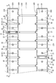
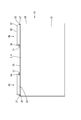
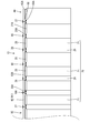
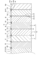
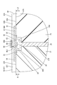
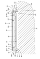
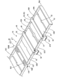
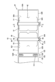
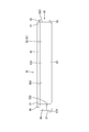
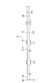
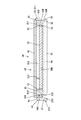
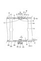
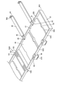
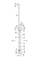
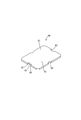
- the perspective view of the electrical storage module concerning one embodiment Plan view of power storage module Front view of power storage module Side view of power storage module AA line sectional view of FIG. Partially enlarged sectional view of FIG. BB sectional view of FIG. Partially enlarged sectional view of FIG. Perspective view of connection module Top view of connection module Front view of connection module Side view of connection module CC sectional view of FIG. DD sectional view of FIG.
- the perspective view which shows the state before a bus bar is arrange
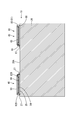
- FIG. 7 is a partially enlarged sectional view showing a state of a bus bar according to the height of an electrode terminal of an adjacent storage element, and is a partially enlarged sectional view corresponding to the section of FIG. 6.
- the partial expanded plan view which showed the state of the connection part according to the space
- the present embodiment is a power storage module 10 mounted on a vehicle such as an electric vehicle or a hybrid vehicle, and as shown in FIG. 1, a power storage device group 20 configured by arranging a plurality of power storage devices 21 in the left-right direction; A connection module 40 attached to the power storage element group 20 is provided.
- the power storage element 21 is a secondary battery, and is formed in a flat rectangular parallelepiped shape that is long in the front-rear direction, as shown in FIGS. 1 and 2.
- a pair of electrode terminals 22 are provided at positions near both ends in the front-rear direction on the upper surface 21 ⁇ / b> A of the storage element 21.
- One of the pair of electrode terminals 22 is a positive electrode terminal, and the other is a negative electrode terminal.
- Each electrode terminal 22 has a substantially rectangular shape that is slightly long in the front-rear direction.
- the upper part of each electrode terminal 22 is formed horizontally, and a protrusion 24 slightly projecting upward from the electrode terminal 22 is provided integrally with the electrode terminal 22 on the upper surface 22A of each electrode terminal 22. Yes.
- the protrusion 24 has a substantially cylindrical shape, and is disposed at a substantially central portion in the front-rear direction of the electrode terminal 22 and at a substantially central portion in the left-right direction of the electrode terminal 22.
- Each electrode terminal 22 is supported by an insulating support portion 25 made of synthetic resin that surrounds the entire side surface of the electrode terminal 22 with the upper end portion of the electrode terminal 22 protruding slightly upward. .
- the storage element group 20 is arranged such that the polarity of the electrode terminal 22 is reversed every predetermined number (three in the present embodiment) of the storage elements 21, and between the adjacent storage elements 21, Flat insulating separators 26 made of synthetic resin are arranged and arranged.
- the insulating separator 26 is arranged along the surface 21B where the adjacent power storage elements 21 face each other.
- the upper end portion of the insulating separator 26 (the end portion on the side where the electrode terminal 22 of the power storage element 21 is disposed) is projected on both sides in the direction in which the power storage elements 21 are arranged, and the upper surface 26A of the insulating separator 26 is It is a horizontal surface along the direction in which the electricity storage elements 21 are arranged.
- an interelement recess 28 having a substantially rectangular shape in a side view is formed on the upper part of the power storage element group 20 and is constituted by the respective insulating support portions 25 of the adjacent power storage elements 21 and the upper surface 26A of the insulating separator 26. Yes.
- connection module 40 is attached to the upper part of the electricity storage element group 20 as shown in FIGS. 1 to 8, and as shown in FIG. 1 and FIG. They are respectively assembled so as to be along two rows of electrode terminals 22 arranged side by side. That is, in the power storage module 10 of the present embodiment, the two connection modules 40 are assembled on the top of the power storage element group 20 side by side on the front and rear sides. In addition, the two connection modules 40 assembled to the power storage element group 20 are configured to connect three power storage elements 21 in parallel to form one power storage unit, and connect the power storage units in series. Each connection module 40 is different in configuration of a bus bar holding portion 81 of an insulation protector 80 to be described later, but is common in other configurations. Therefore, the connection module 40 disposed on the rear side of the power storage element group 20. Will be described as a representative.
- connection module 40 includes a bus bar 60 that connects the electrode terminals 22 of the adjacent storage elements 21, and an insulation protector 80 that holds the bus bar 60.
- the bus bar 60 is formed by, for example, pressing a metal plate having excellent conductivity such as copper, copper alloy, aluminum, aluminum alloy, stainless steel (SUS), or the like.
- the bus bar 60 is formed in a substantially rectangular plate having a substantially rectangular shape that is long in the front-rear direction, and both ends in the left-right direction of the bus bar 60 are connected to the electrode terminals 22 of the electricity storage device 21. It is set as a pair of terminal connection part 61 mounted and connected.
- the pair of terminal connecting portions 61 are placed on the electrode terminals 22 of the adjacent power storage elements 21 when the connection module 40 is assembled to the power storage element group 20. And the electrode terminal 22 of the electrical storage element 21 adjacent is electrically connected by connecting the electrode terminal 22 of the electrical storage element 21 and the corresponding terminal connection part 61 by well-known welding means, such as laser welding, for example. It has become so.
- each terminal connection part 61 in the bus bar 60 has the maximum variation amount of the interval (interelectrode pitch) between the adjacent electrode terminals 22 and the length dimension in the left-right direction of the connection region of the electrode terminal 22 with the terminal connection part 61.
- Each terminal connecting portion 61 is formed to have a length dimension that is greater in the left-right direction than the sum, and when the storage elements 21 are arranged in the left-right direction, even when the inter-electrode pitch in the adjacent storage elements 21 varies. Is arranged on the electrode terminal 22.
- the protrusions are formed on the long outer side surface 60A of the bus bar 60 on the side where the pair of terminal connection portions 61 are arranged.
- a positioning recess 62 into which 24 is fitted is provided.
- the positioning recess 62 is formed to be recessed from the longitudinal outer side surface 60 ⁇ / b> A of the bus bar 60 toward the center of the bus bar 60, and the inner peripheral surface of the positioning recess 62 is formed in an arc shape along the outer peripheral surface of the protrusion 24. Yes.
- the protrusion 24 is fitted in the positioning recess 62 with a clearance between the inner peripheral surface of the positioning recess 62 and the outer peripheral surface of the protrusion 24. . Then, when the pair of terminal connection portions 61 of the bus bar 60 are placed on the respective electrode terminals 22 of the adjacent power storage elements 21, a clearance is provided between the inner peripheral surface of the positioning recess 62 and the outer peripheral surface of the protrusion 24. However, since the bus bar 60 and the protrusion 24 are locked, the terminal connection portion 61 of the bus bar 60 is prevented from being displaced from front to back and right and left from the electrode terminal 22 of the power storage element 21.
- the insulation protector 80 is made of a synthetic resin and has an elongated shape in the left-right direction as shown in FIGS. 1, 2, 9, and 10, and a bus bar holding portion 81 that holds a plurality of bus bars 60.
- the plurality of bus bar holding portions 81 are configured to include a connecting portion 100 that connects the storage elements 21 in the arrangement direction (left-right direction).
- Each bus bar holding portion 81 has a flat, substantially rectangular shape that is long in the left-right direction. As shown in FIG. 9, the bus bar 60 that houses the bus bar 60 and the bus bar 60 that is housed in the housing frame 82 are positioned downward. And a plurality of lids 90 that prevent the bus bar 60 housed in the housing frame 82 from coming out from above, which is the direction opposite to the support portion 84.
- the housing frame 82 is formed in a flat, substantially rectangular frame shape that is long in the left-right direction, and a plurality of bus bars 60 are arranged in the left-right direction in the housing frame 82. It has become.
- the bus bar holding portion 81 at the right end of the connection module 40 disposed on the rear side of the power storage element group 20 and the left end (not shown) holds the three bus bars 60.
- the connection module 40 arranged on the rear side of the group 20 the other bus bar holding parts 81 except for the right end and the left end, and all the bus bar holding parts of the connection module 40 arranged on the rear side of the power storage element group 20. 81 is configured to hold five bus bars 60.
- the storage frame 82 extends in the arrangement direction of the power storage elements 21 and is arranged at a pair of long side walls 82 ⁇ / b> B facing each other in a direction orthogonal to the arrangement direction, and at both left and right ends of the storage frame 82. It is comprised by the short side wall (an example of a "wall part") 82A which connects a pair of long side wall 82B to the direction orthogonal to a direction. As shown in FIGS. 4 and 9, projecting pieces 83 projecting downward from the long side wall 82 ⁇ / b> B of the housing frame 82 are provided at the lower portions of the short side walls 82 ⁇ / b> A.
- connection module 40 In a state where the connection module 40 is attached to the power storage element group 20, the protruding piece 83 can be locked in the left-right direction with respect to the insulating support portion 25 in the power storage element 21, and the bus bar holding portion 81 is connected to the power storage element group. It is possible to prevent the position from being displaced in the left-right direction with respect to 20.
- each support portion 84 has a shape elongated in the front-rear direction, connects the long side walls 82 ⁇ / b> B of the storage frame 82, and lowers the lower surface of the storage frame 82 (the “second end surface”).
- It is provided in parallel with the short side wall 82A of the housing frame 82 so as to be continuous with 82D.
- each support portion 84 supports between the pair of terminal connection portions 61 in the bus bar 60, and the upper surface 84 ⁇ / b> A of the support portion 84 and the lower surface 82 ⁇ / b> D of the housing frame 82 are in the same plane. Formed in position.
- each support portion 84 has a substantially central portion in the left-right direction of the bus bar 60 so that the lower surface of each bus bar 60 and the lower surface 82D of the storage frame 82 are substantially flush with each other in a state of protruding downward from the storage frame 82.
- the bus bar 60 is held in the housing frame 82 by being supported from above.
- each support portion 84 is arranged on the insulating separator 26 of the power storage element group 20 when the connection module 40 is attached to the power storage element group 20. Thereby, a pair of terminal connection parts 61 of each bus bar 60 are arranged on the electrode terminals 22 of each power storage element 21.
- a positioning projection piece 88 that fits into the inter-element recess 28 of the power storage element group 20 is provided in a form protruding downward.
- the positioning protrusion 88 has a reverse trapezoidal plate shape protruding downward from the support portion 84, and the protrusion dimension L ⁇ b> 1 of the positioning protrusion 88 from the housing frame 82 is The depth dimension L ⁇ b> 2 of the inter-element recess 28 of the power storage element group 20 is set.
- the positioning protrusion 88 is formed by the inclined guide portions 88 ⁇ / b> A provided on both lateral sides of the positioning protrusion 88. It is designed to be guided inside.
- the positioning protrusion 88 is fitted from above into the inter-element recess 28 with a gap between the insulating support portion 25 and the upper surface 26A of the insulating separator 26.
- the positioning protrusion 88 and the insulating support portion 25 are locked in the left-right direction, so that the bus bar holding portion 81 is left and right with respect to the electrode terminal 22. It is possible to prevent displacement in the direction.
- a held claw 89 is provided on the outer surface 88B of the lower end portion of the positioning protrusion 88.
- the held claw 89 protrudes outward at a lower end portion of the positioning projection piece 88, which is a direction away from the positioning projection piece 88, and is formed over the entire lower end portion of the positioning projection piece 88.
- the lid 90 is elongated in the front-rear direction, and one end of the lid 90 is connected to the housing frame 82 by a hinge 95.
- the hinge 95 is formed so as to be continuous with the outer surface of the short side portion 91 of the lid portion 90 and the outer surface of the long side wall 82B of the housing frame 82, and the hinge 95 is bent so that the hinge 95 is folded.
- the lid 90 is formed at a position where it can be arranged in a state of facing the support 84 and the bus bar 60.
- the inner surface 90A facing the support portion 84 and the bus bar 60 in the lid portion 90 is also against the upper surface (an example of “first end surface”) 82U of the housing frame 82 as shown in FIG. It is arranged at the facing position where the removal is completed.
- the width dimension of the lid 90 is set to be larger in the left-right direction than the width dimension of the support 84, and when the lid 90 is disposed at the removal completion position, the lid 90 is approximately the center in the left-right direction of the bus bar 60. It is arranged on the top, and the lid 90 can prevent the bus bar 60 from coming off in the housing frame 82.
- a locking piece 94 that locks with a locking frame 86 provided on the housing frame 82 is provided.
- the locking piece 94 protrudes from the outer surface of the lid 90 opposite to the outer surface where the hinge 95 is provided.
- the hinge 95 is bent, as shown in FIG. 94 has a form extending from the cover 90 toward the housing frame 82.
- a locking claw 94A that protrudes toward the hinge 95 side is provided at the tip of the locking piece 94.
- the locking frame 86 of the housing frame 82 is formed so as to protrude from the long side wall 82B in a substantially rectangular shape in plan view.
- the outer surface 82O of the long side wall 82B in the locking frame 86 is provided with a hooked claw 86A that protrudes into the locking frame 86, and the hinge 95 is bent to bring the lid portion 90 into the removal completion position.
- the tip of the locking piece 94 is fitted into the locking frame 86, and the locking claw 94A of the locking piece 94 and the locked claw 86A of the locking frame 86 are locked in the vertical direction.
- the lid 90 is held at the removal completion position.
- a positioning protrusion 87 having the same shape as the positioning protrusion 88 adjacent to the support portion 84 is provided at the lower end of the locking frame 86.
- the positioning protrusion 87 is provided with a held claw 87A that protrudes outward, which is a direction away from the housing frame 82.
- the held claw 87A is formed over the entire lower end portion of the locking frame 86, and together with the held claw 89 on the positioning protrusion 88 of the housing frame 82, is locked with the holding portion 27 provided on the insulating separator 26. It is supposed to be.
- the holding portion 27 of the insulating separator 26 is configured to rise upward from the upper surface 26 ⁇ / b> A of the insulating separator 26.
- the holding portions 27 are provided at a total of four locations, one pair on each of the front and rear sides of the position where the connection module 40 is disposed in each insulating separator 26.
- Each holding portion 27 has a holding protrusion 27A that protrudes toward the connection module 40.
- the connection module 40 is assembled to the power storage element group 20, the holding claws 87A and 89 are held with the holding claws 87A and 89.
- the connection module 40 is fixed to the power storage element group 20 by the protrusion 27 ⁇ / b> A engaging in the vertical direction.
- the connecting part 100 is formed to be connected to the bus bar holding part 81 adjacent in the arrangement direction (left-right direction) of the power storage elements 21.
- a pair of connecting portions 100 is provided at both front and rear ends of a pair of short side walls 82 ⁇ / b> A that face each other in adjacent bus bar holding portions 81.
- Each connecting portion 100 is formed between the short side walls 82 ⁇ / b> A of the adjacent bus bar holding portions 81 and at a position that does not protrude outward from the position of the long side wall 82 ⁇ / b> B of the bus bar holding portion 81.
- Each connecting portion 100 includes a bent portion 101 bent in a horizontal direction in a U shape in plan view, and a pair of base end portions 103 connected to an end portion of the bent portion 101 and a short side wall 82A of the bus bar holding portion 81. Configured.
- the front connecting portion 100F provided at the front end portion of the short side wall 82A and the rear connecting portion 100R provided at the rear end portion of the short side wall 82A are front and rear with respect to a substantially central portion in the front-rear direction of the short side wall 82A.
- the bent portion 101 in each connecting portion 100 elastically expands and contracts in the left-right direction so that the interval between the bus bar holding portions 81 can be changed. Yes.
- the dimension by which the bent portion 101 can be elastically expanded and contracted in the left-right direction is set to be larger than the maximum amount of displacement between the bus bar holding portions 81 that occurs when the power storage elements 21 are arranged in the left-right direction.
- the fitting recess 63 in the bus bar 60 is provided in a substantially central portion of the short outer side surface 60B of the bus bar 60 in the left-right direction.
- the fitting recess 63 has a shape that is recessed from the short outer surface 60 ⁇ / b> B toward the center of the bus bar 60.
- the fitting recess 63 includes a straight portion 64 provided in parallel with the long outer surface 60A, and a curved portion 65 provided in an arc shape so as to be connected to the end of the straight portion 64 and the short outer surface 60B. Has been.
- the retaining portion 85 is formed to be continuous with the support portion 84 inside the position where the hinge 95 is provided in the housing frame 82. Further, the retaining portion 85 projects in a semicircular shape from the inner surface 82I of the long side wall 82B into the housing frame 82, and extends from the upper surface 84A of the support portion 84 over the entire height of the short side wall 82A. Is formed.
- the tolerance absorbing clearance CL1 has a length dimension L3 in the left-right direction between the corner portion 66 where the curved portion 65 and the short outer surface 60B of the bus bar 60 are continuous and the retaining portion 85. It is set to be larger than the length dimension L4 in the front-rear direction.
- the tolerance absorbing clearance CL1 is set to be larger than the length dimension of the accommodation clearance CL2 which is a gap between the inner surface 82I of the long side wall 82B and the short outer surface 60B of the bus bar 60 at any location.
- the protruding dimension L5 of the retaining portion 85 that protrudes from the inner surface 82I of the long side wall 82B into the housing frame 82 is set to be larger than the housing clearance CL2.
- the inner surface of the lid 90 (the upper end position of the retaining portion 85) 90A A height absorption clearance CL3 is provided between the upper surface of the bus bar 60.
- the height absorption clearance CL3 is set to be larger than the maximum variation amount of the height position of the electrode terminal 22 of the adjacent power storage element 21.
- the length L3 between the corner portion 66 of the bus bar 60 and the retaining portion 85 of the bus bar holding portion 81 in the tolerance absorption clearance CL1 is such that one terminal connecting portion 61 of the bus bar 60 is, for example, the upper surface of the housing frame 82. (Example of “first end face”) When arranged on 82U, the other terminal connection portion 61 of the bus bar 60 can be arranged on the lower surface (an example of “second end face”) 82D of the housing frame 82.
- the size is set.
- the bus bar 60 in a state where the bus bar 60 is supported from below in the housing frame 82 by the support portion 84, the bus bar 60 can be moved back and forth and left and right within the range of the tolerance absorption clearance CL1, but the fitting recess 63 of the bus bar 60 is provided.
- the curved portion 65 and the retaining portion 85 are locked in the left-right direction so that the bus bar 60 is held in the housing frame 82 in a state of being prevented from coming off in the left-right direction.
- the retaining portion 85 does not become an obstacle to the inclination of the bus bar 60.
- connection module 40 This embodiment is configured as described above, and the operation and effect of the connection module 40 will be described next.
- the bus bar 60 is arranged with a tolerance absorbing clearance CL1 between the bus bar 60 and the retaining portion 85 of the bus bar holding portion 81 and with a clearance between the protrusion 24 of the electrode terminal 22.
- the bus bar 60 is movable in the direction in which the power storage elements 21 are arranged within each clearance.
- the terminal connection portion 61 of the bus bar 60 is set to be larger than the sum of the maximum variation amount in the pitch between the electrodes of the adjacent power storage elements 21 and the length dimension of the connection region of the electrode terminal 22 with the terminal connection portion 61. Yes.
- the bus bars 60 are within the clearances. Since the bus bar 60 can move in the direction in which the power storage elements 21 are arranged, the adjacent power storage elements 21 can be reliably connected by the bus bar 60.
- the bus bar holding portion 81 is positioned in the inter-element recess 28 of the power storage element group 20 by the positioning protrusions 87 and 88, the bus bar holding portion 81 adjacent in the left and right direction is a connecting portion that can be expanded and contracted in the left and right direction.
- 100 since the accumulated error of the pitch between the electrodes generated between the bus bar holding portions 81 due to the variation in the dimensional accuracy of the electricity storage element 21 increases, as shown in FIG. By accumulating 100 in the left-right direction, it is possible to absorb the accumulated error of the inter-electrode pitch that occurs between the bus bar holding portions 81. Thereby, when attaching the connection module 40 to the power storage element group 20, it is possible to prevent a problem in the mounting work due to a dimensional error in the arrangement direction of the power storage elements 21.
- the storage element 21 may vary in dimensional accuracy even with respect to the height position of the electrode terminal 22.
- a height absorption clearance CL3 is provided between the bus bar 60 housed in the housing frame 82 and the inner surface 90A (the upper end position of the retaining portion 85) of the lid portion 90.
- the length L3 between the corner portion 66 of the bus bar 60 and the retaining portion 85 of the bus bar holding portion 81 in the tolerance absorbing clearance CL1 is the retaining portion even when the bus bar 60 is most inclined in the left-right direction within the housing frame.
- 85 is set to a size that does not hinder the inclination of the bus bar 60.
- the bus bar 60 is moved in the left-right direction even in the case where a positional deviation occurs in the height position of the electrode terminal 22 in the adjacent storage element 21 due to the dimensional error of the storage element 21.
- the position shift of the electrode terminal 22 between adjacent power storage elements can be absorbed, and each terminal connection portion 61 of the bus bar 60 can be placed on the electrode terminal 22 of the adjacent power storage element 21.
- the retaining portion 85 is provided over the entire height of the housing frame 82 in a form protruding inward from the inner surface 82I of the long side wall 82B of the housing frame 82, and left and right of the short outer side surface 60B of the bus bar 60.
- a pair of fitting recesses 63 into which the retaining portions 85 are fitted are provided in the central portion in the direction.
- a means for preventing the bus bar from coming off by a retaining portion by providing a fitting protrusion on the bus bar and providing a fitting groove on the inner surface of the housing frame for fitting the fitting protrusion may be considered.
- the fitting groove is formed in the housing frame, it is necessary to make the plate thickness of the housing frame larger than the depth dimension of the fitting groove, and the housing frame and thus the insulation protector are increased in size.
- the fitting recess 63 of the bus bar 60 is fitted to the retaining portion 85 protruding from the housing frame 82, the bus bar 60 is prevented by the retaining portion 85 while suppressing an increase in the size of the housing frame 82. Can be prevented from coming off in the left-right direction.
- the retaining portion 85 has a semi-cylindrical shape whose projecting surface forms an arc shape, and the fitting recess 63 of the bus bar 60 is recessed so as to follow the projecting surface of the retaining portion 85.
- the bus bar 60 can be smoothly moved in the vertical direction along the retaining portion 85 as compared with the case where the protruding surface is angular.
- connection portion 100 is provided continuously between the pair of short side walls 82A facing each other in the adjacent storage frames 82 and is bent between the adjacent storage frames 82, for example, the connection portion As compared with the case where the projection protrudes outward from between the housing frames, it is possible to suppress the connection module 40 and, consequently, the power storage module 10 from increasing in size.
- connection part 100 is each provided in the front-and-rear both ends of 82 A of short side walls of the storage frame 82, compared with the case where a connection part is provided only in one edge part of a short side wall, for example. It is possible to prevent the connecting portion 100 from being damaged by plastic deformation or the like by opening the housing frame 82 away from each other.
- the power storage units in which the three power storage elements 21 are connected in parallel by the two connection modules 40 are connected in series.
- the present invention is not limited to this, and all the power storage elements may be connected in series by changing the number of bus bars held in the bus bar holding unit, and power storage units in which two or more power storage elements are connected in parallel are connected in series. You may make it the structure which connects.
- the connecting part 100 has the bent part 101 bent in the horizontal direction.
- the present invention is not limited to this, and the connecting portion may have a bent portion that bends in the vertical direction.
- connection module 20 storage element group 21: storage element 22: electrode terminal 25: insulation support part 40: connection module 60: bus bar 61: terminal connection part 63: fitting recess 80: insulation protector 82: housing frame 82A: short side wall (" An example of “wall” 82U: Upper surface of storage frame (example of “first end surface”) 82D: Lower surface of the storage frame (an example of “second end surface”) 85: Stopping portions 87, 88: Positioning portion 100: Connection portion CL1: Tolerance absorption clearance (an example of “clearance”) CL3: Clearance in the height direction (equivalent to “the difference between the height dimension of the retaining part and the thickness dimension of the bus bar”)
Landscapes
- Chemical & Material Sciences (AREA)
- Chemical Kinetics & Catalysis (AREA)
- Electrochemistry (AREA)
- General Chemical & Material Sciences (AREA)
- Engineering & Computer Science (AREA)
- Power Engineering (AREA)
- Microelectronics & Electronic Packaging (AREA)
- Connection Of Batteries Or Terminals (AREA)
- Battery Mounting, Suspending (AREA)
- Electric Double-Layer Capacitors Or The Like (AREA)
- Sealing Battery Cases Or Jackets (AREA)
Priority Applications (2)
| Application Number | Priority Date | Filing Date | Title |
|---|---|---|---|
| CN201980022700.1A CN111937185B (zh) | 2018-04-16 | 2019-04-03 | 连接模块及蓄电模块 |
| US17/044,575 US11502378B2 (en) | 2018-04-16 | 2019-04-03 | Connection module and electricity storage module |
Applications Claiming Priority (2)
| Application Number | Priority Date | Filing Date | Title |
|---|---|---|---|
| JP2018078156A JP7006474B2 (ja) | 2018-04-16 | 2018-04-16 | 接続モジュールおよび蓄電モジュール |
| JP2018-078156 | 2018-04-16 |
Publications (1)
| Publication Number | Publication Date |
|---|---|
| WO2019202991A1 true WO2019202991A1 (ja) | 2019-10-24 |
Family
ID=68238872
Family Applications (1)
| Application Number | Title | Priority Date | Filing Date |
|---|---|---|---|
| PCT/JP2019/014807 Ceased WO2019202991A1 (ja) | 2018-04-16 | 2019-04-03 | 接続モジュールおよび蓄電モジュール |
Country Status (4)
| Country | Link |
|---|---|
| US (1) | US11502378B2 (enExample) |
| JP (1) | JP7006474B2 (enExample) |
| CN (1) | CN111937185B (enExample) |
| WO (1) | WO2019202991A1 (enExample) |
Cited By (1)
| Publication number | Priority date | Publication date | Assignee | Title |
|---|---|---|---|---|
| WO2021161587A1 (ja) * | 2020-02-14 | 2021-08-19 | 三洋電機株式会社 | 電池モジュール |
Families Citing this family (8)
| Publication number | Priority date | Publication date | Assignee | Title |
|---|---|---|---|---|
| JP7078664B2 (ja) * | 2020-04-07 | 2022-05-31 | 矢崎総業株式会社 | バスバーモジュール |
| JP7295060B2 (ja) * | 2020-06-11 | 2023-06-20 | プライムアースEvエナジー株式会社 | 組電池 |
| JP7786966B2 (ja) * | 2022-02-01 | 2025-12-16 | トヨタ自動車株式会社 | 蓄電モジュール |
| DE102022106554B3 (de) | 2022-03-21 | 2023-07-20 | Dr. Ing. H.C. F. Porsche Aktiengesellschaft | Batteriezelle und Batterieanordnung |
| KR102700540B1 (ko) * | 2022-08-05 | 2024-08-28 | 주식회사 엘지에너지솔루션 | 구획 플레이트부가 적용된 배터리 모듈 및 이를 포함하는 배터리 팩 |
| JP7686356B2 (ja) * | 2022-11-29 | 2025-06-02 | 矢崎総業株式会社 | バスバモジュール、及び該バスバモジュール組付け方法 |
| JP2024086142A (ja) * | 2022-12-16 | 2024-06-27 | 株式会社オートネットワーク技術研究所 | 配線モジュール |
| JP7779874B2 (ja) * | 2023-04-05 | 2025-12-03 | 矢崎総業株式会社 | バスバーモジュール |
Citations (5)
| Publication number | Priority date | Publication date | Assignee | Title |
|---|---|---|---|---|
| JP2012138333A (ja) * | 2010-12-07 | 2012-07-19 | Sumitomo Wiring Syst Ltd | バッテリ接続具 |
| JP2013157125A (ja) * | 2012-01-27 | 2013-08-15 | Yazaki Corp | 端子固定構造及び電源装置 |
| JP2015088464A (ja) * | 2013-09-24 | 2015-05-07 | 株式会社Gsユアサ | 蓄電装置 |
| US20150214534A1 (en) * | 2014-01-27 | 2015-07-30 | Ford Global Technologies, Llc | Devices and methods for connecting battery cells |
| JP2016100247A (ja) * | 2014-11-25 | 2016-05-30 | 株式会社オートネットワーク技術研究所 | 配線モジュール |
Family Cites Families (10)
| Publication number | Priority date | Publication date | Assignee | Title |
|---|---|---|---|---|
| JP3707595B2 (ja) | 1998-09-09 | 2005-10-19 | 矢崎総業株式会社 | バッテリ接続プレート |
| KR100868255B1 (ko) * | 2005-04-19 | 2008-11-11 | 주식회사 엘지화학 | 단자 연결장치 |
| JP5612904B2 (ja) * | 2010-05-13 | 2014-10-22 | 矢崎総業株式会社 | カバー部材及び該カバー部材を備えた電源装置 |
| JP5668555B2 (ja) * | 2011-03-18 | 2015-02-12 | 株式会社オートネットワーク技術研究所 | 電池モジュール |
| CN104737328B (zh) * | 2012-10-26 | 2017-03-08 | 三洋电机株式会社 | 电源装置以及具备电源装置的电动车辆及蓄电装置、电源装置的制造方法 |
| JP6164489B2 (ja) * | 2014-01-21 | 2017-07-19 | 株式会社オートネットワーク技術研究所 | 配線モジュール |
| JP6465354B2 (ja) * | 2015-05-28 | 2019-02-06 | 株式会社オートネットワーク技術研究所 | 蓄電モジュール |
| JP6335864B2 (ja) * | 2015-11-20 | 2018-05-30 | 矢崎総業株式会社 | バスバー保持構造 |
| JP2017212128A (ja) * | 2016-05-26 | 2017-11-30 | 株式会社オートネットワーク技術研究所 | 接続モジュール |
| JP7028105B2 (ja) * | 2018-08-29 | 2022-03-02 | 住友電装株式会社 | 電池配線モジュール |
-
2018
- 2018-04-16 JP JP2018078156A patent/JP7006474B2/ja active Active
-
2019
- 2019-04-03 CN CN201980022700.1A patent/CN111937185B/zh active Active
- 2019-04-03 US US17/044,575 patent/US11502378B2/en active Active
- 2019-04-03 WO PCT/JP2019/014807 patent/WO2019202991A1/ja not_active Ceased
Patent Citations (5)
| Publication number | Priority date | Publication date | Assignee | Title |
|---|---|---|---|---|
| JP2012138333A (ja) * | 2010-12-07 | 2012-07-19 | Sumitomo Wiring Syst Ltd | バッテリ接続具 |
| JP2013157125A (ja) * | 2012-01-27 | 2013-08-15 | Yazaki Corp | 端子固定構造及び電源装置 |
| JP2015088464A (ja) * | 2013-09-24 | 2015-05-07 | 株式会社Gsユアサ | 蓄電装置 |
| US20150214534A1 (en) * | 2014-01-27 | 2015-07-30 | Ford Global Technologies, Llc | Devices and methods for connecting battery cells |
| JP2016100247A (ja) * | 2014-11-25 | 2016-05-30 | 株式会社オートネットワーク技術研究所 | 配線モジュール |
Cited By (1)
| Publication number | Priority date | Publication date | Assignee | Title |
|---|---|---|---|---|
| WO2021161587A1 (ja) * | 2020-02-14 | 2021-08-19 | 三洋電機株式会社 | 電池モジュール |
Also Published As
| Publication number | Publication date |
|---|---|
| JP7006474B2 (ja) | 2022-01-24 |
| CN111937185B (zh) | 2023-01-17 |
| CN111937185A (zh) | 2020-11-13 |
| JP2019186138A (ja) | 2019-10-24 |
| US11502378B2 (en) | 2022-11-15 |
| US20210203039A1 (en) | 2021-07-01 |
Similar Documents
| Publication | Publication Date | Title |
|---|---|---|
| WO2019202991A1 (ja) | 接続モジュールおよび蓄電モジュール | |
| US9425520B2 (en) | Battery wiring module | |
| JP5585846B2 (ja) | 電池配線モジュール | |
| JP6465196B1 (ja) | 蓄電モジュール、及び接続モジュール | |
| US9406920B2 (en) | Electrical connector and fuel cell | |
| JP5720448B2 (ja) | 電池配線モジュール | |
| WO2013021964A1 (ja) | 電池配線モジュールのカバー、及び電池配線モジュール | |
| US11289775B2 (en) | Battery wiring module including elastic joiners | |
| WO2017187996A1 (ja) | 接続モジュール | |
| JP6593166B2 (ja) | 配線モジュール | |
| JP6878320B2 (ja) | 接続モジュール用カバー、および接続モジュール | |
| JP5796746B2 (ja) | 配線モジュール | |
| JP2015035323A (ja) | バスバモジュール | |
| JP5648610B2 (ja) | 電池配線モジュール | |
| JP7324428B2 (ja) | 蓄電装置 | |
| JP7077932B2 (ja) | 接続モジュール | |
| JP2024029413A (ja) | バスバー保持部材及び電池モジュール | |
| JP5673495B2 (ja) | 配線モジュール | |
| JP2017004645A (ja) | 配線モジュール | |
| JP2023086381A (ja) | 端子の保持構造、及び、バスバーモジュール | |
| WO2021235198A1 (ja) | 接続モジュール |
Legal Events
| Date | Code | Title | Description |
|---|---|---|---|
| 121 | Ep: the epo has been informed by wipo that ep was designated in this application |
Ref document number: 19788820 Country of ref document: EP Kind code of ref document: A1 |
|
| NENP | Non-entry into the national phase |
Ref country code: DE |
|
| 122 | Ep: pct application non-entry in european phase |
Ref document number: 19788820 Country of ref document: EP Kind code of ref document: A1 |