WO2019202913A1 - Parking-brake control device for vehicle - Google Patents
Parking-brake control device for vehicle Download PDFInfo
- Publication number
- WO2019202913A1 WO2019202913A1 PCT/JP2019/012338 JP2019012338W WO2019202913A1 WO 2019202913 A1 WO2019202913 A1 WO 2019202913A1 JP 2019012338 W JP2019012338 W JP 2019012338W WO 2019202913 A1 WO2019202913 A1 WO 2019202913A1
- Authority
- WO
- WIPO (PCT)
- Prior art keywords
- vehicle
- parking brake
- parking
- switching operation
- operation unit
- Prior art date
Links
Images


Classifications
-
- B—PERFORMING OPERATIONS; TRANSPORTING
- B60—VEHICLES IN GENERAL
- B60T—VEHICLE BRAKE CONTROL SYSTEMS OR PARTS THEREOF; BRAKE CONTROL SYSTEMS OR PARTS THEREOF, IN GENERAL; ARRANGEMENT OF BRAKING ELEMENTS ON VEHICLES IN GENERAL; PORTABLE DEVICES FOR PREVENTING UNWANTED MOVEMENT OF VEHICLES; VEHICLE MODIFICATIONS TO FACILITATE COOLING OF BRAKES
- B60T7/00—Brake-action initiating means
- B60T7/12—Brake-action initiating means for automatic initiation; for initiation not subject to will of driver or passenger
-
- B—PERFORMING OPERATIONS; TRANSPORTING
- B60—VEHICLES IN GENERAL
- B60T—VEHICLE BRAKE CONTROL SYSTEMS OR PARTS THEREOF; BRAKE CONTROL SYSTEMS OR PARTS THEREOF, IN GENERAL; ARRANGEMENT OF BRAKING ELEMENTS ON VEHICLES IN GENERAL; PORTABLE DEVICES FOR PREVENTING UNWANTED MOVEMENT OF VEHICLES; VEHICLE MODIFICATIONS TO FACILITATE COOLING OF BRAKES
- B60T7/00—Brake-action initiating means
- B60T7/02—Brake-action initiating means for personal initiation
- B60T7/08—Brake-action initiating means for personal initiation hand actuated
- B60T7/085—Brake-action initiating means for personal initiation hand actuated by electrical means, e.g. travel, force sensors
-
- B—PERFORMING OPERATIONS; TRANSPORTING
- B60—VEHICLES IN GENERAL
- B60T—VEHICLE BRAKE CONTROL SYSTEMS OR PARTS THEREOF; BRAKE CONTROL SYSTEMS OR PARTS THEREOF, IN GENERAL; ARRANGEMENT OF BRAKING ELEMENTS ON VEHICLES IN GENERAL; PORTABLE DEVICES FOR PREVENTING UNWANTED MOVEMENT OF VEHICLES; VEHICLE MODIFICATIONS TO FACILITATE COOLING OF BRAKES
- B60T17/00—Component parts, details, or accessories of power brake systems not covered by groups B60T8/00, B60T13/00 or B60T15/00, or presenting other characteristic features
- B60T17/18—Safety devices; Monitoring
- B60T17/22—Devices for monitoring or checking brake systems; Signal devices
-
- B—PERFORMING OPERATIONS; TRANSPORTING
- B60—VEHICLES IN GENERAL
- B60T—VEHICLE BRAKE CONTROL SYSTEMS OR PARTS THEREOF; BRAKE CONTROL SYSTEMS OR PARTS THEREOF, IN GENERAL; ARRANGEMENT OF BRAKING ELEMENTS ON VEHICLES IN GENERAL; PORTABLE DEVICES FOR PREVENTING UNWANTED MOVEMENT OF VEHICLES; VEHICLE MODIFICATIONS TO FACILITATE COOLING OF BRAKES
- B60T7/00—Brake-action initiating means
- B60T7/02—Brake-action initiating means for personal initiation
- B60T7/08—Brake-action initiating means for personal initiation hand actuated
- B60T7/10—Disposition of hand control
- B60T7/107—Disposition of hand control with electrical power assistance
-
- B—PERFORMING OPERATIONS; TRANSPORTING
- B60—VEHICLES IN GENERAL
- B60T—VEHICLE BRAKE CONTROL SYSTEMS OR PARTS THEREOF; BRAKE CONTROL SYSTEMS OR PARTS THEREOF, IN GENERAL; ARRANGEMENT OF BRAKING ELEMENTS ON VEHICLES IN GENERAL; PORTABLE DEVICES FOR PREVENTING UNWANTED MOVEMENT OF VEHICLES; VEHICLE MODIFICATIONS TO FACILITATE COOLING OF BRAKES
- B60T2201/00—Particular use of vehicle brake systems; Special systems using also the brakes; Special software modules within the brake system controller
- B60T2201/06—Hill holder; Start aid systems on inclined road
-
- B—PERFORMING OPERATIONS; TRANSPORTING
- B60—VEHICLES IN GENERAL
- B60T—VEHICLE BRAKE CONTROL SYSTEMS OR PARTS THEREOF; BRAKE CONTROL SYSTEMS OR PARTS THEREOF, IN GENERAL; ARRANGEMENT OF BRAKING ELEMENTS ON VEHICLES IN GENERAL; PORTABLE DEVICES FOR PREVENTING UNWANTED MOVEMENT OF VEHICLES; VEHICLE MODIFICATIONS TO FACILITATE COOLING OF BRAKES
- B60T2201/00—Particular use of vehicle brake systems; Special systems using also the brakes; Special software modules within the brake system controller
- B60T2201/10—Automatic or semi-automatic parking aid systems
-
- B—PERFORMING OPERATIONS; TRANSPORTING
- B60—VEHICLES IN GENERAL
- B60Y—INDEXING SCHEME RELATING TO ASPECTS CROSS-CUTTING VEHICLE TECHNOLOGY
- B60Y2300/00—Purposes or special features of road vehicle drive control systems
- B60Y2300/18—Propelling the vehicle
- B60Y2300/18008—Propelling the vehicle related to particular drive situations
- B60Y2300/18108—Braking
Definitions
- the technology disclosed herein relates to a vehicle parking brake control device that controls a vehicle parking brake.
- a vehicle parking brake control device for controlling a vehicle parking brake, A parking switching operation section provided at a position operable by a vehicle occupant for switching on and off of the parking brake; A vehicle power source switching operation unit provided at a position operable by the occupant for switching on and off the power source of the vehicle;
- the parking brake is controlled, and auto apply control is performed to automatically turn on the parking brake when the vehicle power is operated from on to off by the occupant using the vehicle power source switching operation unit.
- a parking brake control unit In the state where the vehicle power is on, the vehicle is stopped, and the parking brake is off, the off operation on the vehicle power switching operation unit is executed after the off operation on the parking switching operation unit is performed.
- a prohibition condition determination unit that determines that a prohibition condition prohibiting the auto-apply control is satisfied; With The parking brake control unit does not execute the auto-apply control when it is determined that the prohibition condition is satisfied.
- the occupant simply performs the turn-off operation with respect to the parking switching operation portion and the turn-off operation with respect to the vehicle power supply switching operation portion in this order so that the auto-applied control is not easily performed. Can be.
- FIG. 1 It is a block diagram which shows roughly the control structure of a vehicle provided with the parking brake control apparatus of the vehicle of this embodiment. It is a figure which shows roughly the brake mechanism of the vehicle shown by FIG. It is a figure which shows roughly the brake mechanism of the vehicle shown by FIG. It is a figure which shows roughly the brake mechanism of the vehicle shown by FIG. It is a figure which shows roughly the external appearance of the driver's seat periphery of the vehicle shown by FIG. It is a figure which shows roughly the external appearance of the driver's seat periphery of the vehicle shown by FIG. It is a flowchart which shows an example of the operation
- FIG. 9 is a timing chart showing transition of each part in the operations of FIGS. 6 to 8.
- FIG. 9 is a timing chart showing transition of each part in the operations of FIGS. 6 to 8.
- FIG. It is a flowchart which shows roughly an example of the operation
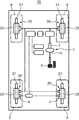
- FIG. 1 is a block diagram schematically showing a control configuration of a vehicle 10 including a vehicle parking brake control device of the present embodiment.
- 2 and 3 are diagrams schematically showing a brake mechanism of the vehicle 10 shown in FIG. 4 and 5 are diagrams schematically showing the external appearance of the vicinity of the driver's seat 58 of the vehicle 10 shown in FIG.
- the vehicle 10 is a four-wheeled vehicle, for example.
- the vehicle 10 includes a foot brake mechanism 2 and an electric parking brake mechanism 4 (corresponding to an example of a parking brake).
- the foot brake mechanism 2 supplies brake fluid pressurized in response to the depression operation of the brake pedal 5 (hereinafter referred to as “brake fluid pressure”) to the two pairs of front and rear hydraulic brake mechanisms 20.
- brake fluid pressure brake fluid pressurized in response to the depression operation of the brake pedal 5 (hereinafter referred to as “brake fluid pressure”) to the two pairs of front and rear hydraulic brake mechanisms 20.
- the two pairs of front and rear wheels 6 can be braked.
- the foot brake mechanism 2 includes a brake pedal 5, a master cylinder 7, a booster 11, a hydraulic brake mechanism 20, and the like.
- the booster 11 has a movable wall (not shown) that can move in the axial direction in conjunction with the brake pedal 5, and the brake pedal uses the differential pressure between the negative pressure chamber and the atmospheric chamber partitioned by the movable wall. Boosting the stepping force of 5.
- the hydraulic brake mechanism 20 provided on each of the four wheels 6 is connected to the master cylinder 7 by a pipe line 27 and applies a braking force to each wheel 6 according to the depression operation of the brake pedal 5 by the occupant. .
- each hydraulic brake mechanism 20 includes a rotor disk 21 provided on the wheel 6 so as to be integrally rotatable, a caliper 22 capable of applying a braking force to the rotor disk 21, and the like.
- the caliper 22 includes a caliper main body 23 disposed in a bowl shape on the rotor disk 21, and outer brake pads 24 disposed on both sides of the rotor disk 21 inside the caliper main body 23, and an inner brake pad 24. Side brake pad 25.
- a piston 26 that is movable in the axial direction of the rotor disk 21 is disposed inside the inner brake pad 25.
- the piston 26 is slidably inserted into a cylinder hole 23a formed in the caliper body 23. Has been.
- a pipe line 27 is connected to the cylinder hole 23a.
- the brake fluid pressure flows through the conduit 27 and is supplied to the cylinder hole 23a, and the piston 26 is moved forward in the axial direction.
- the inner brake pad 25 is pressed against the inner side of the rotor disk 21, and the reaction force moves the caliper body 23 toward the inner side, and the outer brake pad 24 is pressed against the outer side of the rotor disk 21.
- the braking force of the foot brake mechanism 2 is generated.
- the electric parking brake mechanism 4 operates independently of the depression operation of the brake pedal 5.
- the electric parking brake mechanism 4 includes a piston 41, an annular member 42, an electric motor 43, and the like.
- a male screw portion 41 a is formed on the inner end side portion of the piston 41, and the male screw portion 41 a and a female screw portion 42 a formed on the inner surface portion of the annular member 42 are screwed together.
- a gear surface portion 42 b is formed on the outer surface portion of the annular member 42, and the gear surface portion 42 b and a pinion 44 attached to the drive shaft of the electric motor 43 so as to be integrally rotatable are screwed together.
- the annular member 42 is rotationally driven, and the piston 41 is moved forward and backward with respect to the axial direction.
- the piston 41 moves forward toward the outside in the axial direction, the inner brake pad 25 and the outer brake pad 24 are pressed against the rotor disk 21, and the braking force of the electric parking brake mechanism 4 is generated.
- the vehicle 10 includes a parking brake control device 90 and an electric motor 43 as shown in FIG.
- the parking brake control device 90 includes a vehicle power switch 100, a vehicle speed sensor 110, a parking switch 120, a gradient sensor 130, a buzzer 150, an indicator lamp 121, and an electronic control unit (ECU) 160.
- ECU 160 includes a central processing unit (CPU) 170, a memory 180, and other peripheral circuits.
- the memory 180 is composed of, for example, a semiconductor memory, a hard disk, or another storage element.
- the memory 180 includes a read only memory (ROM), a random access memory (RAM), and the like.
- the memory 180 may be composed of a single memory having an area for storing a program and an area for temporarily storing data.
- the CPU 170 functions as a parking brake control unit 171, a prohibition condition determination unit 172, a notification control unit 173, and a display control unit 174 by operating according to a program stored in the memory 180. Each function of the CPU 170 will be described later.
- the vehicle power switch 100 (corresponding to an example of a vehicle power switching operation unit) is a switch for switching on / off the power of the vehicle 10.
- the vehicle 10 is turned off and the occupant operates the vehicle power switch 100 while depressing the brake pedal 5, for example, the ignition (power) of the vehicle 10 is turned on.
- the occupant operates the vehicle power switch 100 while the ignition (power) of the vehicle 10 is on, the power of the vehicle 10 is turned off.
- the ignition (power supply) of the vehicle 10 being on means that power is being supplied from the power supply of the vehicle 10 to the vehicle equipment. That the power supply of the vehicle 10 is off means that no power is supplied from the power supply of the vehicle 10 to the vehicle device.
- the vehicle device is, for example, an actuator such as an ignition device for engine control.
- the vehicle speed sensor 110 detects the traveling speed of the vehicle 10 based on the rotational speed of the wheels 6 (FIG. 2), for example.
- the gradient sensor 130 detects the gradient of the vehicle 10 (that is, the gradient of the road on which the vehicle 10 is located). Each sensor 110, 130 outputs a detection value to ECU 160.
- the parking switch 120 (corresponding to an example of a parking switching operation unit) is a switch that is operated by a passenger to switch the electric parking brake mechanism 4 on and off. For example, when the occupant performs an on operation of pulling up the parking switch 120 with a finger, the electric parking brake mechanism 4 that is turned off is turned on. For example, when the occupant performs an off operation of pushing down the parking switch 120 with a finger, the electric parking brake mechanism 4 that is on is turned off. When the occupant removes his / her finger from the parking switch 120, the parking switch 120 returns to the neutral position.
- the electric parking brake mechanism 4 is on” means that the electric parking brake mechanism 4 is in a braking state in which the wheel 6 (FIG. 2) is being braked.
- the electric parking brake mechanism 4 being off means that the electric parking brake mechanism 4 is in a non-braking state in which the wheel 6 (FIG. 2) is not braked.
- the indicator lamp 121 is formed integrally with the parking switch 120.
- the indicator lamp 121 is for notifying an occupant of information related to the operation status of the electric parking brake mechanism 4.
- the indicator lamp 121 is controlled by the display control unit 174 of the CPU 170.
- the parking switch 120 is disposed on the center console 50 and can be easily operated by a passenger seated in the driver's seat 58.
- the vehicle power switch 100 is disposed between the center cluster 54 and the steering wheel 56 so that an occupant seated in the driver's seat 58 can easily operate.
- the parking switch 120 and the vehicle power switch 100 are disposed on the same side with respect to the steering wheel 56.
- the parking switch 120 and the vehicle power switch 100 are arranged on the center side in the width direction X of the vehicle 10 with respect to the steering wheel 56.
- the vehicle power switch 100 employs a push button system in which the occupant pushes and operates with a finger. However, the occupant inserts an ignition key and rotates it. A key cylinder method for operating the projector may be adopted.
- the buzzer 150 (corresponding to an example of a notification unit) is for notifying an occupant of information related to cancellation of auto-applied control.
- the buzzer 150 is controlled by the notification control unit 173 of the CPU 170.
- the parking brake control unit 171 of the CPU 170 controls on / off of the electric parking brake mechanism 4 according to the operation of the parking switch 120.
- the parking brake control unit 171 performs auto-apply control that automatically activates the electric parking brake mechanism 4 when the vehicle 10 is turned off by the occupant using the vehicle power switch 100.
- the prohibition condition determination unit 172 performs an off operation on the vehicle power switch 100 after the off operation on the parking switch 120 is executed in a state where the vehicle 10 is stopped and the electric parking brake mechanism 4 is turned off. Then, it is determined that a prohibition condition for prohibiting auto-apply control is satisfied.
- the parking brake control unit 171 does not execute the auto-apply control when the prohibition condition determination unit 172 determines that the prohibition condition is satisfied.
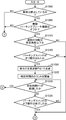
- FIGS. 6 to 8 are flowcharts schematically showing an example of the operation procedure of the vehicle 10.
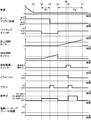
- FIGS. 9 and 10 are timing charts showing transitions of respective parts of the vehicle 10 in the operations of FIGS.
- FIG. 9 shows a case where it is determined that the prohibition condition is satisfied and the auto-apply control is not executed.
- FIG. 10 shows a case where auto-apply control is executed.
- the operations in FIGS. 6 to 8 are executed at regular time intervals (for example, 50 msec).
- step S1000 of FIG. 6 the prohibition condition determination unit 172 determines whether or not the vehicle 10 is stopped. For example, based on the detection value from the vehicle speed sensor 110, the prohibition condition determination unit 172 stops the vehicle 10 when the vehicle speed is kept at a predetermined low speed (for example, 2 to 5 km / h) or less for a predetermined time. It is determined that If vehicle 10 is stopped (YES in step S1000), the process proceeds to step S1005. On the other hand, if vehicle 10 has not stopped (NO in step S1000), the operations in FIGS. 6 to 8 are terminated. 9 and 10, it is determined that the vehicle 10 is stopped at time t1.
- a predetermined low speed for example, 2 to 5 km / h
- step S1005 of FIG. 6 the prohibition condition determination unit 172 determines whether or not the electric parking brake mechanism 4 is off.
- the prohibition condition determination unit 172 determines that the electric parking brake mechanism 4 is off unless the parking brake control unit 171 operates the electric motor 43. If electric parking brake mechanism 4 is off (YES in step S1005), the process proceeds to step S1010. On the other hand, if electric parking brake mechanism 4 is on (NO in step S1005), the operations in FIGS. 6 to 8 are terminated.
- step S1010 the prohibition condition determination unit 172 determines whether or not the road gradient is equal to or less than a predetermined angle based on the detection value from the gradient sensor 130. If the road gradient is equal to or smaller than the predetermined angle (YES in step S1010), the process proceeds to step S1015. On the other hand, if the road gradient exceeds the predetermined angle (NO in step S1010), the process proceeds to step S1200 (FIG. 8).
- step S1015 the prohibition condition determination unit 172 determines whether or not the parking switch 120 is turned off. If parking switch 120 is turned off (YES in step S1015), the process proceeds to step S1020. On the other hand, if parking switch 120 is not turned off (NO in step S1015), the process proceeds to step S1200 (FIG. 8).
- step S1020 the prohibition condition determination unit 172 notifies the display control unit 174 that the parking switch 120 has been turned off.
- the display control unit 174 causes the indicator lamp 121 to blink at the frequency FQ1.
- FQ1 0.5 to 3 [Hz].
- step S1025 the prohibition condition determination unit 172 counts the determination time. 9 and 10, the parking switch 120 is turned off at time t2, the blinking display of the indicator lamp 121 is started, and counting of the determination time is started.
- step S1030 the prohibition condition determination unit 172 determines whether or not the counting determination time has reached a predetermined time T1. If the determination time has reached predetermined time T1 (YES in step S1030), the process proceeds to step S1100 (FIG. 7). On the other hand, if the determination time has not reached predetermined time T1 (NO in step S1030), the process proceeds to step S1035.
- step S1035 the prohibition condition determination unit 172 determines whether or not the parking switch 120 is turned off. If the parking switch 120 has not been turned off (NO in step S1035), the process returns to step S1030 and the above steps are repeated. If the parking switch 120 has been turned off (YES in step S1035), the process proceeds to step S1200 (FIG. 8).
- the off operation of the parking switch 120 for a short period of time less than the predetermined time T1 is not an off operation for preventing the auto-apply control from being executed, but is handled as an off operation performed erroneously. It is.
- the prohibition condition determination unit 172 notifies the parking brake control unit 171 and the notification control unit 173 that the determination time has reached the predetermined time T1.
- the parking brake control unit 171 shifts the auto-apply control from the permission mode to the prohibit mode.
- the notification control unit 173 operates the buzzer 150 for a predetermined time. 9 and 10, at time t3 when the predetermined time T1 has elapsed from time t2, the auto-apply control is shifted from the permission mode to the prohibit mode, and the buzzer 150 is operating for a predetermined time. By operating the buzzer 150, the passenger is notified that an operation for preventing the auto-apply control from being executed has been received.
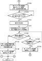
- step S1105 of FIG. 7 the prohibition condition determination unit 172 determines whether or not the parking switch 120 has been turned off. If the parking switch 120 is not turned off (NO in step S1105), the process waits. When the parking switch 120 off operation ends (YES in step S1105), the prohibition condition determination unit 172 notifies the display control unit 174 that the parking switch 120 off operation has ended.
- step S1110 the display control unit 174 turns off the indicator lamp 121.
- step S1115 the prohibition condition determination unit 172 finishes counting the determination time and starts counting the prohibition time. 9 and 10, the indicator lamp 121 is turned off at the time t4 when the turning-off operation of the parking switch 120 is completed, the determination time is counted, and the prohibition time is started.
- the prohibition condition determination unit 172 determines whether or not the power of the vehicle 10 has been turned off by turning off the vehicle power switch 100. If the vehicle 10 is not turned off (NO in step S1120), the process proceeds to step S1125. On the other hand, if the vehicle 10 is powered off (YES in step S1120), the process proceeds to step S1130.
- step S1125 the prohibition condition determination unit 172 determines whether the counting prohibition time has reached a predetermined time T2. If the prohibition time has not reached the predetermined time T2 (NO in step S1125), the process returns to step S1120 and the above steps are repeated. On the other hand, if the prohibition time has reached predetermined time T2 (YES in step S1125), the process proceeds to step S1140. In other words, if the vehicle power switch 100 is turned off before the prohibited time reaches the predetermined time T2, the process proceeds to step S1130, while the vehicle power switch 100 is turned off until the prohibited time reaches the predetermined time T2. If not operated, the process proceeds to step S1140.
- step S1130 the prohibition condition determination unit 172 notifies the notification control unit 173, the display control unit 174, and the parking brake control unit 171 that the power of the vehicle 10 has been turned off.
- the notification control unit 173 operates the buzzer 150 for a predetermined time.
- the display control unit 174 causes the indicator lamp 121 to blink at a frequency FQ2 for a predetermined time.
- the parking brake control unit 171 does not execute the auto-apply control (step S1135), and ends the operations of FIGS.
- the vehicle power switch 100 is operated at time t5, and the ignition of the vehicle 10 is turned off immediately after time t6. Then, from time t6, the buzzer 150 operates for a predetermined time, the indicator lamp 121 blinks for a predetermined time, and the passenger is notified that the auto-applied control is not executed. Then, the electric parking brake mechanism 4 is finished without being turned on.
- the prohibition condition determination unit 172 notifies the parking brake control unit 171 that the prohibition time has reached the predetermined time T2 without the vehicle 10 being turned off.
- the parking brake control unit 171 shifts the auto apply control from the prohibit mode to the permission mode.
- the auto-apply control is shifted from the prohibit mode to the permission mode.
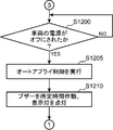
- step S1200 of FIG. 8 the parking brake control unit 171 determines whether or not the power of the vehicle 10 is turned off when the vehicle power switch 100 is turned off. If the vehicle 10 is not turned off (NO in step S1200), it waits. On the other hand, if the power supply of vehicle 10 is turned off (YES in step S1200), the process proceeds to step S1205.
- step S1205 the parking brake control unit 171 operates the electric motor 43 to execute auto-apply control for turning on the electric parking brake mechanism 4.
- the parking brake control unit 171 notifies the notification control unit 173 and the display control unit 174 that the electric parking brake mechanism 4 is turned on.
- the notification control unit 173 operates the buzzer 150 for a predetermined time.
- the display control unit 174 turns on the indicator lamp 121. Then, the operations in FIGS. 6 to 8 are finished.
- the vehicle power switch 100 is operated at time t8, and the ignition of the vehicle 10 is turned off immediately after time t9. Then, the electric parking brake mechanism 4 is turned on. Further, the indicator lamp 121 is turned on, the buzzer 150 is operated for a predetermined time, and the passenger is notified that the electric parking brake mechanism 4 is turned on.
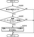
- FIG. 11 is a flowchart schematically showing an example of an operation procedure related to the control of the electric parking brake mechanism 4.
- the operation of FIG. 11 is executed at regular time intervals (for example, 50 msec).
- step S2000 the parking brake control unit 171 determines whether or not the ignition of the vehicle 10 is turned off. If the ignition of vehicle 10 is off (YES in step S2000), the process proceeds to step S2005. On the other hand, if the ignition of vehicle 10 is on (NO in step S2000), the operation in FIG. 11 ends.
- step S2005 the parking brake control unit 171 determines whether or not the electric parking brake mechanism 4 is turned on by operating the electric motor 43. If electric parking brake mechanism 4 is on (YES in step S2005), the process proceeds to step S2010. On the other hand, if the electric parking brake mechanism 4 is off (NO in step S2005), the operation in FIG. 11 ends. In step S2010, the parking brake control unit 171 prohibits turning off the electric parking brake mechanism 4 and ends the operation of FIG.
- the auto-apply control is shifted from the permission mode to the prohibition mode.
- the auto-apply control is prohibited. It is determined that the condition is met. If it is determined that the prohibition condition is satisfied, the auto-apply control is not executed. Therefore, the occupant can easily prevent the auto-apply control from being executed only by performing the turn-off operation on the parking switch 120 and the turn-off operation on the vehicle power switch 100 in this order.
- the auto-applied control is not shifted from the permission mode to the prohibit mode. For this reason, when the OFF operation for the parking switch 120 is mistakenly performed for a short time less than the predetermined time T1, the auto-apply control is not prohibited. Therefore, it is possible to cope with an erroneous operation of the parking switch 120.
- the present embodiment there is a prohibition condition for prohibiting the auto-applied control if the off operation for the vehicle power switch 100 is not executed from when the off operation for the parking switch 120 is completed until the predetermined time T2 elapses. It is not determined that it has been established. Therefore, when the occupant wants to execute the auto-apply control after performing the off operation on the parking switch 120, the time from when the off operation on the parking switch 120 is completed until the predetermined time T2 elapses. In the meantime, the off operation for the vehicle power switch 100 may not be executed. Thus, according to the present embodiment, it is possible to cope with a change in the schedule of the occupant.
- the parking switch 120 is depressed even when the ignition of the vehicle 10 is turned off and the electric parking brake mechanism 4 is turned on. Even if it is turned off, the electric parking brake mechanism 4 is not turned off. Therefore, the electric parking brake mechanism 4 is not inadvertently turned off. For this reason, according to this embodiment, it is possible to improve the safety of the vehicle 10.
- the vehicle 10 may further include a range sensor 140 as shown in FIG.
- Range sensor 140 detects the position of shift lever 52 (FIG. 5) (that is, shift range).
- Range sensor 140 outputs the detection result to ECU 160.
- the prohibition condition determination unit 172 may further determine that the prohibition condition is satisfied when the position of the shift lever 52 (FIG. 5) detected by the range sensor 140 is the neutral position.
- the shift lever 52 (FIG. 5) What is necessary is just to add the determination step of whether a position is a neutral position.
- the position of the shift lever 52 (FIG. 5) is set to the neutral position, for example, when the vehicle 10 breaks down and is pulled by another vehicle, the vehicle 10 is washed at a car wash station in Europe.
- the auto apply control can be prevented from being executed.
- the vehicle 10 includes the buzzer 150 for notifying the occupant, but the member notifying the occupant is not limited to the buzzer.
- a speaker may be provided and notified to the occupant by voice.
- the parking switch 120 and the vehicle power switch 100 are arranged with respect to the steering wheel 56 disposed on the right side in the traveling direction of the vehicle 10. It is arranged on the left side.
- the parking switch 120 and the vehicle power switch 100 are arranged on the right side with respect to the steering wheel 56. do it.
- the parking switch 120 and the vehicle power switch 100 may be disposed on the same side with respect to the steering wheel 56 (FIGS. 4 and 5) of the vehicle 10.
- the parking switch 120 and the vehicle power switch 100 may be disposed on the center side in the width direction X of the vehicle 10 with respect to the steering wheel 56 of the vehicle 10.
- the parking switch 120 off operation and the vehicle power switch 100 off operation are executed simultaneously, it is conceivable that the auto-apply control is not executed.
- the positional relationship between the parking switch 120 and the vehicle power switch 100 is the modified embodiment or the above-described embodiment, the parking switch 120 is turned off and the vehicle power switch 100 is turned off. In order to carry out simultaneously using both hands, it is difficult to twist the body while sitting in the driver's seat 58, which is difficult.
- the occupant can easily prevent the auto-applied control from being executed only by performing the turn-off operation for the parking switch and the turn-off operation for the vehicle power switch in this order. . Therefore, a greater effect can be obtained when the positional relationship between the parking switch 120 and the vehicle power switch 100 is the modified embodiment or the embodiment described above.
- a vehicle parking brake control device for controlling a vehicle parking brake, A parking switching operation section provided at a position operable by a vehicle occupant for switching on and off of the parking brake; A vehicle power source switching operation unit provided at a position operable by the occupant for switching on and off the power source of the vehicle;
- the parking brake is controlled, and auto apply control is performed to automatically turn on the parking brake when the vehicle power is operated from on to off by the occupant using the vehicle power source switching operation unit.
- a parking brake control unit In the state where the vehicle power is on, the vehicle is stopped, and the parking brake is off, the off operation on the vehicle power switching operation unit is executed after the off operation on the parking switching operation unit is performed.
- a prohibition condition determination unit that determines that a prohibition condition prohibiting the auto-apply control is satisfied; With The parking brake control unit does not execute the auto-apply control when it is determined that the prohibition condition is satisfied.
- the off operation on the vehicle power switching operation unit is performed after the off operation on the parking switching operation unit is performed. Then, it is determined that a prohibition condition for prohibiting auto-apply control is established. If it is determined that the prohibition condition is satisfied, the auto-apply control is not executed. Therefore, according to this aspect, the occupant simply performs the turn-off operation with respect to the parking switching operation unit and the turn-off operation with respect to the vehicle power supply switching operation unit in this order so that the auto-applied control is not easily performed. Can do.
- the information processing apparatus further includes a notification unit that notifies the occupant that the auto-apply control is not executed.
- the occupant when it is determined that the prohibition condition is satisfied, the occupant is notified that the auto-apply control is not executed. Therefore, according to this aspect, the occupant can easily recognize that the auto-apply control is not executed.
- the prohibition condition determination unit determines that the off operation for the parking switching operation unit is executed when the off operation for the parking switching operation unit is continued for a predetermined time or more.
- the parking brake control unit does not turn off the parking brake even when an off operation is performed on the parking switching operation unit when the vehicle is powered off and the parking brake is on. It is.
- the parking brake when the vehicle is powered off and the parking brake is on, the parking brake is turned off even if the occupant mistakenly turns off the parking switching operation unit. Not. Therefore, according to this aspect, the safety of the vehicle can be improved.
- the prohibition condition determination unit further determines that the prohibition condition is satisfied when a slope of the road is equal to or less than a predetermined angle.
- the prohibition condition is satisfied when the slope of the road on which the vehicle is located is equal to or less than a predetermined angle. In other words, when the slope of the road on which the vehicle is located exceeds a predetermined angle, it is not determined that the prohibition condition is satisfied. Therefore, according to this aspect, when the slope of the road on which the vehicle is located exceeds a predetermined angle, the auto-apply control is executed. For this reason, even when it is forgotten to turn on the parking switching operation section, it is possible to prevent the parking brake from being turned off and the vehicle from moving due to the road gradient.
- the prohibition condition determination unit further determines that the prohibition condition is satisfied when the shift lever is in a neutral position.
- the auto-apply control is not performed. be able to.
- the parking switching operation unit and the vehicle power supply switching operation unit are arranged on the same side in the width direction of the vehicle with respect to the steering wheel of the vehicle.
- the auto-apply control is not executed when the parking switching operation unit OFF operation and the vehicle power supply switching operation unit OFF operation are performed simultaneously.
- the parking switching operation unit and the vehicle power supply switching operation unit are arranged on the same side in the vehicle width direction with respect to the steering wheel of the vehicle. For this reason, in order to simultaneously execute the off operation of the parking switching operation unit and the off operation of the vehicle power supply switching operation unit using both hands, it is necessary to twist the body while sitting in the driver's seat. It has become difficult.
- the occupant simply performs the turn-off operation on the parking switching operation unit and the turn-off operation on the vehicle power supply switching operation unit in this order so that the auto-applied control is not easily performed. be able to. Therefore, a greater effect can be obtained when the positional relationship between the parking switching operation unit and the vehicle power supply switching operation unit is in this mode.
- the parking switching operation unit and the vehicle power supply switching operation unit are arranged on the center side in the width direction of the vehicle with respect to the steering wheel of the vehicle.
- the auto-apply control is not executed when the parking switching operation unit OFF operation and the vehicle power supply switching operation unit OFF operation are performed simultaneously.
- the parking switching operation unit and the vehicle power supply switching operation unit are disposed on the center side in the vehicle width direction with respect to the steering wheel of the vehicle. For this reason, in order to simultaneously execute the off operation of the parking switching operation unit and the off operation of the vehicle power supply switching operation unit using both hands, it is necessary to twist the body while sitting in the driver's seat. It has become difficult.
- the occupant simply performs the turn-off operation on the parking switching operation unit and the turn-off operation on the vehicle power supply switching operation unit in this order so that the auto-applied control is not easily performed. be able to. Therefore, a greater effect can be obtained when the positional relationship between the parking switching operation unit and the vehicle power supply switching operation unit is in this mode.
- a vehicle parking brake control device for controlling a parking brake for braking a wheel, A parking switching operation unit provided at a position operable by an occupant of the vehicle for switching between a braking state and a non-braking state of the parking brake; A vehicle power supply switching operation section provided at a position operable by the occupant for switching between an on state and an off state of the vehicle power supply; In the state where the vehicle power is on, the vehicle is stopped, and the parking brake is not braked, When the vehicle power source switching operation unit is operated by the occupant to turn off the vehicle power source, the parking brake is switched from a non-braking state to a braking state, After the occupant operated the parking brake to the non-braking state using the parking switching operation unit, the occupant operated the vehicle power supply to the off state using the vehicle power switching operation unit.
- a parking brake control unit for maintaining the parking brake in a non-braking state; It is what has.
- the parking brake when the vehicle power source is turned on, the vehicle is stopped, and the parking brake is not braked, the occupant operates the vehicle power source switching operation unit to turn off the vehicle power source.
- the parking brake is switched from the non-braking state to the braking state. Therefore, according to this aspect, even if the occupant forgets to operate the parking switching operation unit, the parking brake can be automatically set to the braking state.
- the occupant uses the parking switching operation unit to operate the parking brake to the non-braking state.
- the parking brake is maintained in the non-braking state when the vehicle power supply is turned off using the power switching operation unit. Therefore, according to this aspect, the occupant operates the parking brake using the parking switching operation unit to the non-braking state and the vehicle power switching operation using the vehicle power switching operation unit in this order.
- the parking brake can be easily maintained in the non-braking state simply by performing the above.
Landscapes
- Engineering & Computer Science (AREA)
- Transportation (AREA)
- Mechanical Engineering (AREA)
- Regulating Braking Force (AREA)
- Valves And Accessory Devices For Braking Systems (AREA)
Abstract
Provided is a parking-brake control device for a vehicle, comprising: a parking switching operation unit for switching on/off of a parking brake; a vehicle power switching operation unit for switching on/off of power of the vehicle; a parking-brake control unit that controls the parking brake and executes automatic application control when the power of the vehicle is operated from on to off by an occupant with use of the vehicle power switching operation unit; and a prohibition condition determination unit that determines that a prohibition condition to prohibit the automatic application control has been established when off-operation to the vehicle power switching operation unit is executed after off-operation to the parking switching operation unit is executed in a state when the power of the vehicle is on, the vehicle is stopped, and the parking brake is off. The parking brake control unit does not execute automatic application control when it is determined that the prohibition condition has been established.
Description
ここに開示された技術は、車両のパーキングブレーキを制御する車両のパーキングブレーキ制御装置に関するものである。
The technology disclosed herein relates to a vehicle parking brake control device that controls a vehicle parking brake.
従来、車両の電源がオフにされたときに、電動パーキングブレーキを自動的に作動させるオートアプライ制御が知られている(例えば、特許文献1参照)。また、特許文献2に記載の技術では、ブレーキペダルが踏まれている状態で、車両電源スイッチがオフにされると、電動パーキングブレーキを自動的に作動させるオートアプライ制御が実行されている。
Conventionally, auto-apply control is known in which an electric parking brake is automatically operated when a vehicle is turned off (see, for example, Patent Document 1). Further, in the technique described in Patent Document 2, when the vehicle power switch is turned off while the brake pedal is being depressed, auto-apply control that automatically operates the electric parking brake is executed.
例えば故障したときなどに車両を牽引する際には、パーキングブレーキをオフにする必要がある。また、欧州の洗車場では、一般に、左右の一方輪のみをベルトコンベヤに乗せて、自動洗車機まで車両を移動させて自動洗車が行われるので、パーキングブレーキをオフにしておく必要がある。このように、車両電源スイッチにより車両の電源がオフにされたときに電動パーキングブレーキが自動的に作動するオートアプライ制御を実行したくない場合がある。そこで、乗員の操作によりオートアプライ制御が実行されないようにすることを容易に可能にすることが求められる。
For example, when towing a vehicle when it breaks down, it is necessary to turn off the parking brake. Further, in European car wash stations, generally, only one of the left and right wheels is placed on a belt conveyor, and the vehicle is moved to the automatic car wash machine for automatic car wash. Therefore, it is necessary to turn off the parking brake. As described above, there is a case where it is not desired to execute the auto-apply control in which the electric parking brake automatically operates when the vehicle power is turned off by the vehicle power switch. Therefore, it is required to easily enable the auto-apply control not to be executed by a passenger operation.
ここに開示された技術は、乗員の操作によりオートアプライ制御が実行されないようにすることを容易に可能にする車両のパーキングブレーキ制御装置を提供することを目的とする。
It is an object of the technology disclosed herein to provide a parking brake control device for a vehicle that can easily prevent auto-apply control from being executed by an occupant's operation.
上述の課題を解決するために、ここに開示された技術の一態様は、
車両のパーキングブレーキを制御する車両のパーキングブレーキ制御装置であって、
前記車両の乗員により操作可能な位置に設けられ前記パーキングブレーキのオンオフを切り換えるためのパーキング切り換え操作部と、
前記乗員により操作可能な位置に設けられ前記車両の電源のオンオフを切り換えるための車両電源切り換え操作部と、
前記パーキングブレーキを制御するとともに、前記車両電源切り換え操作部を用いて前記乗員により前記車両の電源がオンからオフに操作されると、前記パーキングブレーキを自動的にオンにさせるオートアプライ制御を実行するパーキングブレーキ制御部と、
前記車両の電源がオン状態、前記車両が停止した状態、かつ前記パーキングブレーキがオフの状態において、前記パーキング切り換え操作部に対するオフ操作が実行された後に、前記車両電源切り換え操作部に対するオフ操作が実行されると、前記オートアプライ制御を禁止する禁止条件が成立したと判定する禁止条件判定部と、
を備え、
前記パーキングブレーキ制御部は、前記禁止条件が成立したと判定されると、前記オートアプライ制御を実行しないものである。 In order to solve the above-described problem, one aspect of the technology disclosed herein is as follows:
A vehicle parking brake control device for controlling a vehicle parking brake,
A parking switching operation section provided at a position operable by a vehicle occupant for switching on and off of the parking brake;
A vehicle power source switching operation unit provided at a position operable by the occupant for switching on and off the power source of the vehicle;
The parking brake is controlled, and auto apply control is performed to automatically turn on the parking brake when the vehicle power is operated from on to off by the occupant using the vehicle power source switching operation unit. A parking brake control unit;
In the state where the vehicle power is on, the vehicle is stopped, and the parking brake is off, the off operation on the vehicle power switching operation unit is executed after the off operation on the parking switching operation unit is performed. A prohibition condition determination unit that determines that a prohibition condition prohibiting the auto-apply control is satisfied;
With
The parking brake control unit does not execute the auto-apply control when it is determined that the prohibition condition is satisfied.
この車両のパーキングブレーキ制御装置によれば、乗員が、パーキング切り換え操作部に対するオフ操作と車両電源切り換え操作部に対するオフ操作とを、この順番で行うだけで、容易に、オートアプライ制御が実行されないようにすることができる。
According to this vehicle parking brake control device, the occupant simply performs the turn-off operation with respect to the parking switching operation portion and the turn-off operation with respect to the vehicle power supply switching operation portion in this order so that the auto-applied control is not easily performed. Can be.
以下、図面を参照しつつ、本開示の実施形態が説明される。なお、各図では、同様の要素には同様の符号が付され、適宜、説明が省略される。
Hereinafter, embodiments of the present disclosure will be described with reference to the drawings. In each figure, the same numerals are given to the same element, and explanation is omitted suitably.
図1は、本実施形態の車両のパーキングブレーキ制御装置を備える車両10の制御構成を概略的に示すブロック図である。図2、図3は、図1に示される車両10のブレーキ機構を概略的に示す図である。図4、図5は、図1に示される車両10の運転席58周辺の外観を概略的に示す図である。車両10は、例えば4輪自動車である。
FIG. 1 is a block diagram schematically showing a control configuration of a vehicle 10 including a vehicle parking brake control device of the present embodiment. 2 and 3 are diagrams schematically showing a brake mechanism of the vehicle 10 shown in FIG. 4 and 5 are diagrams schematically showing the external appearance of the vicinity of the driver's seat 58 of the vehicle 10 shown in FIG. The vehicle 10 is a four-wheeled vehicle, for example.
図2、図3に示されるように、車両10は、フットブレーキ機構2と、電動パーキングブレーキ機構4(パーキングブレーキの一例に相当)とを備える。フットブレーキ機構2は、ブレーキペダル5の踏込操作に応じて加圧されたブレーキ液(以下、「ブレーキ液圧」と称される)を前後2対の液圧ブレーキ機構20に供給することにより、前後2対の車輪6を制動可能に構成されている。
2 and 3, the vehicle 10 includes a foot brake mechanism 2 and an electric parking brake mechanism 4 (corresponding to an example of a parking brake). The foot brake mechanism 2 supplies brake fluid pressurized in response to the depression operation of the brake pedal 5 (hereinafter referred to as “brake fluid pressure”) to the two pairs of front and rear hydraulic brake mechanisms 20. The two pairs of front and rear wheels 6 can be braked.
フットブレーキ機構2は、ブレーキペダル5、マスタシリンダ7、ブースタ11、液圧ブレーキ機構20等を含む。ブースタ11は、ブレーキペダル5に連動して軸方向に移動可能な可動壁(図示省略)を有し、この可動壁によって区画された負圧室と大気室との差圧を利用してブレーキペダル5の踏み込み力を倍力している。4個の車輪6にそれぞれ設けられた液圧ブレーキ機構20は、管路27によってマスタシリンダ7に接続され、乗員によるブレーキペダル5の踏込操作に応じて各車輪6に制動力を付与している。
The foot brake mechanism 2 includes a brake pedal 5, a master cylinder 7, a booster 11, a hydraulic brake mechanism 20, and the like. The booster 11 has a movable wall (not shown) that can move in the axial direction in conjunction with the brake pedal 5, and the brake pedal uses the differential pressure between the negative pressure chamber and the atmospheric chamber partitioned by the movable wall. Boosting the stepping force of 5. The hydraulic brake mechanism 20 provided on each of the four wheels 6 is connected to the master cylinder 7 by a pipe line 27 and applies a braking force to each wheel 6 according to the depression operation of the brake pedal 5 by the occupant. .
図3に示されるように、各液圧ブレーキ機構20は、車輪6に一体回転可能に設けられたロータディスク21、このロータディスク21に制動力を付与可能なキャリパ22等を備えている。キャリパ22は、ロータディスク21に鞍状に跨って配設されたキャリパ本体23と、このキャリパ本体23の内部にてロータディスク21を挟んでその両側に配設されたアウタ側ブレーキパッド24とインナ側ブレーキパッド25とを備えている。インナ側ブレーキパッド25の内側には、ロータディスク21の軸心方向に移動可能なピストン26が配設され、このピストン26は、キャリパ本体23に形成されたシリンダ孔23aに摺動可能に嵌挿されている。シリンダ孔23aには管路27が接続されている。
As shown in FIG. 3, each hydraulic brake mechanism 20 includes a rotor disk 21 provided on the wheel 6 so as to be integrally rotatable, a caliper 22 capable of applying a braking force to the rotor disk 21, and the like. The caliper 22 includes a caliper main body 23 disposed in a bowl shape on the rotor disk 21, and outer brake pads 24 disposed on both sides of the rotor disk 21 inside the caliper main body 23, and an inner brake pad 24. Side brake pad 25. A piston 26 that is movable in the axial direction of the rotor disk 21 is disposed inside the inner brake pad 25. The piston 26 is slidably inserted into a cylinder hole 23a formed in the caliper body 23. Has been. A pipe line 27 is connected to the cylinder hole 23a.
乗員がブレーキペダル5を踏込操作すると、ブレーキ液圧が管路27を流れてシリンダ孔23aに供給され、ピストン26を軸心方向外側に向けて前進させる。これに伴いインナ側ブレーキパッド25がロータディスク21の内側に押し付けられ、この反力により、キャリパ本体23が内側に移動し、アウタ側ブレーキパッド24がロータディスク21の外側に押し付けられる。以上により、フットブレーキ機構2の制動力が発生する。
When the occupant depresses the brake pedal 5, the brake fluid pressure flows through the conduit 27 and is supplied to the cylinder hole 23a, and the piston 26 is moved forward in the axial direction. As a result, the inner brake pad 25 is pressed against the inner side of the rotor disk 21, and the reaction force moves the caliper body 23 toward the inner side, and the outer brake pad 24 is pressed against the outer side of the rotor disk 21. As a result, the braking force of the foot brake mechanism 2 is generated.
電動パーキングブレーキ機構4は、ブレーキペダル5の踏込操作とは、独立して作動する。電動パーキングブレーキ機構4は、図3に示されるように、ピストン41、円環状部材42、電動モータ43等を含む。ピストン41の内端側部分には、雄ねじ部41aが形成され、この雄ねじ部41aと円環状部材42の内面部に形成された雌ねじ部42aとが螺合している。円環状部材42の外面部には、ギヤ面部42bが形成され、このギヤ面部42bと電動モータ43の駆動軸に一体回転可能に取り付けられたピニオン44とが螺合している。これにより、電動モータ43を駆動することで、円環状部材42が回転駆動され、ピストン41を軸心方向に対して進退移動させている。ピストン41が軸心方向の外側に向けて前進すると、インナ側ブレーキパッド25及びアウタ側ブレーキパッド24がロータディスク21に押し付けられて、電動パーキングブレーキ機構4の制動力が発生する。
The electric parking brake mechanism 4 operates independently of the depression operation of the brake pedal 5. As shown in FIG. 3, the electric parking brake mechanism 4 includes a piston 41, an annular member 42, an electric motor 43, and the like. A male screw portion 41 a is formed on the inner end side portion of the piston 41, and the male screw portion 41 a and a female screw portion 42 a formed on the inner surface portion of the annular member 42 are screwed together. A gear surface portion 42 b is formed on the outer surface portion of the annular member 42, and the gear surface portion 42 b and a pinion 44 attached to the drive shaft of the electric motor 43 so as to be integrally rotatable are screwed together. Thereby, by driving the electric motor 43, the annular member 42 is rotationally driven, and the piston 41 is moved forward and backward with respect to the axial direction. When the piston 41 moves forward toward the outside in the axial direction, the inner brake pad 25 and the outer brake pad 24 are pressed against the rotor disk 21, and the braking force of the electric parking brake mechanism 4 is generated.
車両10は、図1に示されるように、パーキングブレーキ制御装置90、電動モータ43を備える。パーキングブレーキ制御装置90は、車両電源スイッチ100、車速センサ110、パーキングスイッチ120、勾配センサ130、ブザー150、表示灯121、電子制御ユニット(ECU)160を備える。ECU160は、中央演算処理装置(CPU)170、メモリ180、その他の周辺回路を含む。
The vehicle 10 includes a parking brake control device 90 and an electric motor 43 as shown in FIG. The parking brake control device 90 includes a vehicle power switch 100, a vehicle speed sensor 110, a parking switch 120, a gradient sensor 130, a buzzer 150, an indicator lamp 121, and an electronic control unit (ECU) 160. ECU 160 includes a central processing unit (CPU) 170, a memory 180, and other peripheral circuits.
メモリ180は、例えば、半導体メモリ、ハードディスク、又は他の記憶素子で構成される。メモリ180は、リードオンリメモリ(ROM)、ランダムアクセスメモリ(RAM)等を含む。なお、メモリ180は、プログラムを保存する領域、データを一時的に保存する領域を備えた単一のメモリで構成されていてもよい。
The memory 180 is composed of, for example, a semiconductor memory, a hard disk, or another storage element. The memory 180 includes a read only memory (ROM), a random access memory (RAM), and the like. The memory 180 may be composed of a single memory having an area for storing a program and an area for temporarily storing data.
CPU170は、メモリ180に保存されているプログラムに従って動作することにより、パーキングブレーキ制御部171、禁止条件判定部172、報知制御部173、表示制御部174として機能する。CPU170の各機能は、後述される。
The CPU 170 functions as a parking brake control unit 171, a prohibition condition determination unit 172, a notification control unit 173, and a display control unit 174 by operating according to a program stored in the memory 180. Each function of the CPU 170 will be described later.
車両電源スイッチ100(車両電源切り換え操作部の一例に相当)は、車両10の電源のオンオフを切り換えるためのスイッチである。車両10の電源がオフの状態で、乗員が例えばブレーキペダル5を踏み込みながら車両電源スイッチ100を操作すると、車両10のイグニション(電源)がオンにされる。車両10のイグニション(電源)がオンの状態で、乗員が車両電源スイッチ100を操作すると、車両10の電源がオフにされる。
The vehicle power switch 100 (corresponding to an example of a vehicle power switching operation unit) is a switch for switching on / off the power of the vehicle 10. When the vehicle 10 is turned off and the occupant operates the vehicle power switch 100 while depressing the brake pedal 5, for example, the ignition (power) of the vehicle 10 is turned on. When the occupant operates the vehicle power switch 100 while the ignition (power) of the vehicle 10 is on, the power of the vehicle 10 is turned off.
車両10のイグニション(電源)がオンとは、車両10の電源から車両機器に電力が供給されている状態であることを意味する。車両10の電源がオフとは、車両10の電源から車両機器に電力が供給されていない状態であることを意味する。車両機器は、例えば、エンジン制御のための点火装置等のアクチュエータである。
The ignition (power supply) of the vehicle 10 being on means that power is being supplied from the power supply of the vehicle 10 to the vehicle equipment. That the power supply of the vehicle 10 is off means that no power is supplied from the power supply of the vehicle 10 to the vehicle device. The vehicle device is, for example, an actuator such as an ignition device for engine control.
車速センサ110は、例えば車輪6(図2)の回転速度に基づき、車両10の走行速度を検出する。勾配センサ130は、車両10の勾配(つまり車両10が位置する道路の勾配)を検出する。各センサ110,130は、検出値をECU160に出力する。
The vehicle speed sensor 110 detects the traveling speed of the vehicle 10 based on the rotational speed of the wheels 6 (FIG. 2), for example. The gradient sensor 130 detects the gradient of the vehicle 10 (that is, the gradient of the road on which the vehicle 10 is located). Each sensor 110, 130 outputs a detection value to ECU 160.
パーキングスイッチ120(パーキング切り換え操作部の一例に相当)は、乗員により操作され、電動パーキングブレーキ機構4のオンオフを切り換えるためのスイッチである。乗員が例えば指でパーキングスイッチ120を引き上げるオン操作を行うと、オフになっている電動パーキングブレーキ機構4がオンになる。乗員が例えば指でパーキングスイッチ120を押し下げるオフ操作を行うと、オンになっている電動パーキングブレーキ機構4がオフにされる。パーキングスイッチ120から乗員が指を離すと、パーキングスイッチ120は中立位置に戻る。
The parking switch 120 (corresponding to an example of a parking switching operation unit) is a switch that is operated by a passenger to switch the electric parking brake mechanism 4 on and off. For example, when the occupant performs an on operation of pulling up the parking switch 120 with a finger, the electric parking brake mechanism 4 that is turned off is turned on. For example, when the occupant performs an off operation of pushing down the parking switch 120 with a finger, the electric parking brake mechanism 4 that is on is turned off. When the occupant removes his / her finger from the parking switch 120, the parking switch 120 returns to the neutral position.
電動パーキングブレーキ機構4がオンとは、電動パーキングブレーキ機構4が車輪6(図2)を制動している制動状態であることを意味する。電動パーキングブレーキ機構4がオフとは、電動パーキングブレーキ機構4が車輪6(図2)を制動していない非制動状態であることを意味する。
“The electric parking brake mechanism 4 is on” means that the electric parking brake mechanism 4 is in a braking state in which the wheel 6 (FIG. 2) is being braked. The electric parking brake mechanism 4 being off means that the electric parking brake mechanism 4 is in a non-braking state in which the wheel 6 (FIG. 2) is not braked.
表示灯121は、パーキングスイッチ120と一体的に形成されている。表示灯121は、電動パーキングブレーキ機構4の作動状況に関する情報を乗員に報知するためのものである。表示灯121は、CPU170の表示制御部174によって制御される。
The indicator lamp 121 is formed integrally with the parking switch 120. The indicator lamp 121 is for notifying an occupant of information related to the operation status of the electric parking brake mechanism 4. The indicator lamp 121 is controlled by the display control unit 174 of the CPU 170.
パーキングスイッチ120は、図4、図5に示されるように、センターコンソール50に配置され、運転席58に着座した乗員が容易に操作可能になっている。車両電源スイッチ100は、図4、図5に示されるように、センタークラスター54とステアリングホイール56との間に配置され、運転席58に着座した乗員が容易に操作可能になっている。本実施形態では、図4、図5に示されるように、パーキングスイッチ120と、車両電源スイッチ100とは、ステアリングホイール56に対して同じ側に配置されている。言い換えると、パーキングスイッチ120と、車両電源スイッチ100とは、ステアリングホイール56に対して、車両10の幅方向Xにおける中央側に配置されている。
As shown in FIGS. 4 and 5, the parking switch 120 is disposed on the center console 50 and can be easily operated by a passenger seated in the driver's seat 58. As shown in FIGS. 4 and 5, the vehicle power switch 100 is disposed between the center cluster 54 and the steering wheel 56 so that an occupant seated in the driver's seat 58 can easily operate. In the present embodiment, as shown in FIGS. 4 and 5, the parking switch 120 and the vehicle power switch 100 are disposed on the same side with respect to the steering wheel 56. In other words, the parking switch 120 and the vehicle power switch 100 are arranged on the center side in the width direction X of the vehicle 10 with respect to the steering wheel 56.
なお、本実施形態では、車両電源スイッチ100は、図4、図5に示されるように、乗員が指で押して操作する押しボタン方式が採用されているが、乗員がイグニションキーを差し込んで回転させて操作するキーシリンダー方式が採用されていてもよい。
In this embodiment, as shown in FIGS. 4 and 5, the vehicle power switch 100 employs a push button system in which the occupant pushes and operates with a finger. However, the occupant inserts an ignition key and rotates it. A key cylinder method for operating the projector may be adopted.
ブザー150(報知部の一例に相当)は、オートアプライ制御のキャンセルに関する情報を乗員に報知するためのものである。ブザー150は、CPU170の報知制御部173によって制御される。
The buzzer 150 (corresponding to an example of a notification unit) is for notifying an occupant of information related to cancellation of auto-applied control. The buzzer 150 is controlled by the notification control unit 173 of the CPU 170.
CPU170のパーキングブレーキ制御部171は、パーキングスイッチ120の操作に応じて、電動パーキングブレーキ機構4のオンオフを制御する。パーキングブレーキ制御部171は、車両電源スイッチ100を用いて乗員により車両10の電源がオフに操作されると、電動パーキングブレーキ機構4を自動的に作動させるオートアプライ制御を実行する。
The parking brake control unit 171 of the CPU 170 controls on / off of the electric parking brake mechanism 4 according to the operation of the parking switch 120. The parking brake control unit 171 performs auto-apply control that automatically activates the electric parking brake mechanism 4 when the vehicle 10 is turned off by the occupant using the vehicle power switch 100.
禁止条件判定部172は、車両10が停止した状態、かつ電動パーキングブレーキ機構4がオフにされている状態において、パーキングスイッチ120に対するオフ操作が実行された後に、車両電源スイッチ100に対するオフ操作が実行されると、オートアプライ制御を禁止する禁止条件が成立したと判定する。
The prohibition condition determination unit 172 performs an off operation on the vehicle power switch 100 after the off operation on the parking switch 120 is executed in a state where the vehicle 10 is stopped and the electric parking brake mechanism 4 is turned off. Then, it is determined that a prohibition condition for prohibiting auto-apply control is satisfied.
具体的には、禁止条件判定部172は、パーキングスイッチ120に対するオフ操作が所定時間T1以上継続されると、パーキングスイッチ120に対するオフ操作が実行されたと判定する。本実施形態では、例えばT1=1~5[秒]である。禁止条件判定部172は、パーキングスイッチ120に対するオフ操作が終了してから所定時間T2以内に、車両電源スイッチ100に対するオフ操作が実行されると、禁止条件が成立したと判定する。本実施形態では、例えばT2=3~7[秒]である。パーキングスイッチ120に対するオフ操作が終了した後に、車両電源スイッチ100に対するオフ操作を実行することになるので、T2>T1に設定するのが好ましい。禁止条件判定部172は、更に、勾配センサ130により検出された道路の勾配が所定角度以下のときに、禁止条件が成立したと判定する。所定角度は、例えば±5~15%である。
Specifically, the prohibition condition determination unit 172 determines that the off operation on the parking switch 120 has been executed when the off operation on the parking switch 120 is continued for a predetermined time T1 or more. In the present embodiment, for example, T1 = 1 to 5 [seconds]. The prohibition condition determination unit 172 determines that the prohibition condition is satisfied when the OFF operation for the vehicle power switch 100 is executed within a predetermined time T2 after the OFF operation for the parking switch 120 ends. In the present embodiment, for example, T2 = 3 to 7 [seconds]. Since the off operation on the vehicle power switch 100 is executed after the off operation on the parking switch 120 is completed, it is preferable to set T2> T1. The prohibition condition determination unit 172 further determines that the prohibition condition is satisfied when the road gradient detected by the gradient sensor 130 is equal to or smaller than a predetermined angle. The predetermined angle is, for example, ± 5 to 15%.
パーキングブレーキ制御部171は、禁止条件が成立したと禁止条件判定部172により判定されると、オートアプライ制御を実行しない。
The parking brake control unit 171 does not execute the auto-apply control when the prohibition condition determination unit 172 determines that the prohibition condition is satisfied.
図6~図8は、車両10の動作手順の一例を概略的に示すフローチャートである。図9、図10は、図6~図8の動作における車両10の各部の推移を示すタイミングチャートである。図9は、禁止条件が成立したと判定されてオートアプライ制御が実行されない場合を示す。図10は、オートアプライ制御が実行される場合を示す。図6~図8の動作は、一定時間(例えば50msec)毎に実行される。
FIGS. 6 to 8 are flowcharts schematically showing an example of the operation procedure of the vehicle 10. FIGS. 9 and 10 are timing charts showing transitions of respective parts of the vehicle 10 in the operations of FIGS. FIG. 9 shows a case where it is determined that the prohibition condition is satisfied and the auto-apply control is not executed. FIG. 10 shows a case where auto-apply control is executed. The operations in FIGS. 6 to 8 are executed at regular time intervals (for example, 50 msec).
図6のステップS1000において、禁止条件判定部172は、車両10が停止しているか否かを判定する。禁止条件判定部172は、例えば、車速センサ110からの検出値に基づき、車速が所定の低速度(例えば2~5km/h)以下の状態が所定時間継続されると、車両10は停止していると判定する。車両10が停止していれば(ステップS1000でYES)、処理はステップS1005に進む。一方、車両10が停止していなければ(ステップS1000でNO)、図6~図8の動作は終了する。図9、図10では、時刻t1に、車両10は停止していると判定される。
In step S1000 of FIG. 6, the prohibition condition determination unit 172 determines whether or not the vehicle 10 is stopped. For example, based on the detection value from the vehicle speed sensor 110, the prohibition condition determination unit 172 stops the vehicle 10 when the vehicle speed is kept at a predetermined low speed (for example, 2 to 5 km / h) or less for a predetermined time. It is determined that If vehicle 10 is stopped (YES in step S1000), the process proceeds to step S1005. On the other hand, if vehicle 10 has not stopped (NO in step S1000), the operations in FIGS. 6 to 8 are terminated. 9 and 10, it is determined that the vehicle 10 is stopped at time t1.
図6のステップS1005において、禁止条件判定部172は、電動パーキングブレーキ機構4がオフであるか否かを判定する。禁止条件判定部172は、パーキングブレーキ制御部171が電動モータ43を作動させていなければ、電動パーキングブレーキ機構4がオフであると判定する。電動パーキングブレーキ機構4がオフであれば(ステップS1005でYES)、処理はステップS1010に進む。一方、電動パーキングブレーキ機構4がオンであれば(ステップS1005でNO)、図6~図8の動作は終了する。
In step S1005 of FIG. 6, the prohibition condition determination unit 172 determines whether or not the electric parking brake mechanism 4 is off. The prohibition condition determination unit 172 determines that the electric parking brake mechanism 4 is off unless the parking brake control unit 171 operates the electric motor 43. If electric parking brake mechanism 4 is off (YES in step S1005), the process proceeds to step S1010. On the other hand, if electric parking brake mechanism 4 is on (NO in step S1005), the operations in FIGS. 6 to 8 are terminated.
ステップS1010において、禁止条件判定部172は、勾配センサ130からの検出値に基づき、道路の勾配が所定角度以下であるか否かを判定する。道路の勾配が所定角度以下であれば(ステップS1010でYES)、処理はステップS1015に進む。一方、道路の勾配が所定角度を超えていれば(ステップS1010でNO)、処理はステップS1200(図8)に進む。
In step S1010, the prohibition condition determination unit 172 determines whether or not the road gradient is equal to or less than a predetermined angle based on the detection value from the gradient sensor 130. If the road gradient is equal to or smaller than the predetermined angle (YES in step S1010), the process proceeds to step S1015. On the other hand, if the road gradient exceeds the predetermined angle (NO in step S1010), the process proceeds to step S1200 (FIG. 8).
ステップS1015において、禁止条件判定部172は、パーキングスイッチ120がオフ操作されたか否かを判定する。パーキングスイッチ120がオフ操作されると(ステップS1015でYES)、処理はステップS1020に進む。一方、パーキングスイッチ120がオフ操作されなければ(ステップS1015でNO)、処理はステップS1200(図8)に進む。
In step S1015, the prohibition condition determination unit 172 determines whether or not the parking switch 120 is turned off. If parking switch 120 is turned off (YES in step S1015), the process proceeds to step S1020. On the other hand, if parking switch 120 is not turned off (NO in step S1015), the process proceeds to step S1200 (FIG. 8).
ステップS1020において、禁止条件判定部172は、パーキングスイッチ120がオフ操作されたことを表示制御部174に通知する。表示制御部174は、表示灯121を周波数FQ1で点滅させる。本実施形態では、例えばFQ1=0.5~3[Hz]である。ステップS1025において、禁止条件判定部172は、判定時間をカウントする。図9、図10では、時刻t2に、パーキングスイッチ120がオフ操作され、表示灯121の点滅表示が開始され、判定時間のカウントが開始されている。
In step S1020, the prohibition condition determination unit 172 notifies the display control unit 174 that the parking switch 120 has been turned off. The display control unit 174 causes the indicator lamp 121 to blink at the frequency FQ1. In the present embodiment, for example, FQ1 = 0.5 to 3 [Hz]. In step S1025, the prohibition condition determination unit 172 counts the determination time. 9 and 10, the parking switch 120 is turned off at time t2, the blinking display of the indicator lamp 121 is started, and counting of the determination time is started.
ステップS1030において、禁止条件判定部172は、カウントしている判定時間が所定時間T1に達したか否かを判定する。判定時間が所定時間T1に達していれば(ステップS1030でYES)、処理はステップS1100(図7)に進む。一方、判定時間が所定時間T1に達していなければ(ステップS1030でNO)、処理はステップS1035に進む。
In step S1030, the prohibition condition determination unit 172 determines whether or not the counting determination time has reached a predetermined time T1. If the determination time has reached predetermined time T1 (YES in step S1030), the process proceeds to step S1100 (FIG. 7). On the other hand, if the determination time has not reached predetermined time T1 (NO in step S1030), the process proceeds to step S1035.
ステップS1035において、禁止条件判定部172は、パーキングスイッチ120のオフ操作が終了したか否かを判定する。パーキングスイッチ120のオフ操作が終了していなければ(ステップS1035でNO)、処理はステップS1030に戻って、以上のステップが繰り返される。パーキングスイッチ120のオフ操作が終了していれば(ステップS1035でYES)、処理はステップS1200(図8)に進む。すなわち、本実施形態では、所定時間T1未満の短時間のパーキングスイッチ120のオフ操作は、オートアプライ制御を実行させないようにするためのオフ操作ではなく、誤って行われたオフ操作であると取り扱われている。
In step S1035, the prohibition condition determination unit 172 determines whether or not the parking switch 120 is turned off. If the parking switch 120 has not been turned off (NO in step S1035), the process returns to step S1030 and the above steps are repeated. If the parking switch 120 has been turned off (YES in step S1035), the process proceeds to step S1200 (FIG. 8). In other words, in the present embodiment, the off operation of the parking switch 120 for a short period of time less than the predetermined time T1 is not an off operation for preventing the auto-apply control from being executed, but is handled as an off operation performed erroneously. It is.
図7のステップS1100において、禁止条件判定部172は、判定時間が所定時間T1に達した旨をパーキングブレーキ制御部171及び報知制御部173に通知する。パーキングブレーキ制御部171は、オートアプライ制御を許可モードから禁止モードに遷移する。報知制御部173は、ブザー150を所定時間作動させる。図9、図10では、時刻t2から所定時間T1が経過した時刻t3に、オートアプライ制御が許可モードから禁止モードに遷移され、ブザー150が所定時間作動している。このブザー150の作動によって、乗員に対して、オートアプライ制御を実行させないようにするための操作を受け付けたことが報知される。
7, the prohibition condition determination unit 172 notifies the parking brake control unit 171 and the notification control unit 173 that the determination time has reached the predetermined time T1. The parking brake control unit 171 shifts the auto-apply control from the permission mode to the prohibit mode. The notification control unit 173 operates the buzzer 150 for a predetermined time. 9 and 10, at time t3 when the predetermined time T1 has elapsed from time t2, the auto-apply control is shifted from the permission mode to the prohibit mode, and the buzzer 150 is operating for a predetermined time. By operating the buzzer 150, the passenger is notified that an operation for preventing the auto-apply control from being executed has been received.
図7のステップS1105において、禁止条件判定部172は、パーキングスイッチ120のオフ操作が終了したか否かを判定する。パーキングスイッチ120のオフ操作が終了していなければ(ステップS1105でNO)、待機する。パーキングスイッチ120のオフ操作が終了すると(ステップS1105でYES)、禁止条件判定部172は、パーキングスイッチ120のオフ操作が終了したことを表示制御部174に通知する。
In step S1105 of FIG. 7, the prohibition condition determination unit 172 determines whether or not the parking switch 120 has been turned off. If the parking switch 120 is not turned off (NO in step S1105), the process waits. When the parking switch 120 off operation ends (YES in step S1105), the prohibition condition determination unit 172 notifies the display control unit 174 that the parking switch 120 off operation has ended.
ステップS1110において、表示制御部174は、表示灯121を消灯する。ステップS1115において、禁止条件判定部172は、判定時間のカウントを終了し、禁止時間のカウントを開始する。図9、図10では、パーキングスイッチ120のオフ操作が終了した時刻t4に、表示灯121が消灯し、判定時間のカウントが終了され、禁止時間のカウントが開始されている。
In step S1110, the display control unit 174 turns off the indicator lamp 121. In step S1115, the prohibition condition determination unit 172 finishes counting the determination time and starts counting the prohibition time. 9 and 10, the indicator lamp 121 is turned off at the time t4 when the turning-off operation of the parking switch 120 is completed, the determination time is counted, and the prohibition time is started.
図7のステップS1120において、禁止条件判定部172は、車両電源スイッチ100がオフ操作されたことにより、車両10の電源がオフにされたか否かを判定する。車両10の電源がオフにされていなければ(ステップS1120でNO)、処理はステップS1125に進む。一方、車両10の電源がオフにされていれば(ステップS1120でYES)、処理はステップS1130に進む。
7, the prohibition condition determination unit 172 determines whether or not the power of the vehicle 10 has been turned off by turning off the vehicle power switch 100. If the vehicle 10 is not turned off (NO in step S1120), the process proceeds to step S1125. On the other hand, if the vehicle 10 is powered off (YES in step S1120), the process proceeds to step S1130.
ステップS1125において、禁止条件判定部172は、カウントしている禁止時間が所定時間T2に達したか否かを判定する。禁止時間が所定時間T2に達していなければ(ステップS1125でNO)、ステップS1120に戻って、以上のステップが繰り返される。一方、禁止時間が所定時間T2に達していれば(ステップS1125でYES)、処理はステップS1140に進む。言い換えると、禁止時間が所定時間T2に達するまでに、車両電源スイッチ100がオフ操作されると、処理はステップS1130に進む一方、禁止時間が所定時間T2に達するまでに、車両電源スイッチ100がオフ操作されなければ、処理はステップS1140に進む。
In step S1125, the prohibition condition determination unit 172 determines whether the counting prohibition time has reached a predetermined time T2. If the prohibition time has not reached the predetermined time T2 (NO in step S1125), the process returns to step S1120 and the above steps are repeated. On the other hand, if the prohibition time has reached predetermined time T2 (YES in step S1125), the process proceeds to step S1140. In other words, if the vehicle power switch 100 is turned off before the prohibited time reaches the predetermined time T2, the process proceeds to step S1130, while the vehicle power switch 100 is turned off until the prohibited time reaches the predetermined time T2. If not operated, the process proceeds to step S1140.
ステップS1130において、禁止条件判定部172は、車両10の電源がオフにされたことを報知制御部173、表示制御部174、パーキングブレーキ制御部171に通知する。この通知を受けて、報知制御部173は、ブザー150を所定時間作動させる。また、表示制御部174は、表示灯121を周波数FQ2で所定時間点滅させる。本実施形態では、FQ2>FQ1であり、例えば、FQ2=5~10[Hz]である。そして、パーキングブレーキ制御部171は、オートアプライ制御を実行せずに(ステップS1135)、図6~図8の動作を終了する。
In step S1130, the prohibition condition determination unit 172 notifies the notification control unit 173, the display control unit 174, and the parking brake control unit 171 that the power of the vehicle 10 has been turned off. Upon receiving this notification, the notification control unit 173 operates the buzzer 150 for a predetermined time. Further, the display control unit 174 causes the indicator lamp 121 to blink at a frequency FQ2 for a predetermined time. In the present embodiment, FQ2> FQ1, for example, FQ2 = 5 to 10 [Hz]. Then, the parking brake control unit 171 does not execute the auto-apply control (step S1135), and ends the operations of FIGS.
図9では、時刻t5に、車両電源スイッチ100が操作され、その直後の時刻t6に、車両10のイグニションがオフにされる。そして、時刻t6から、ブザー150が所定時間作動し、表示灯121が所定時間点滅して、乗員に対して、オートアプライ制御が実行されないことが報知される。そして、電動パーキングブレーキ機構4がオンにされないまま、終了している。
In FIG. 9, the vehicle power switch 100 is operated at time t5, and the ignition of the vehicle 10 is turned off immediately after time t6. Then, from time t6, the buzzer 150 operates for a predetermined time, the indicator lamp 121 blinks for a predetermined time, and the passenger is notified that the auto-applied control is not executed. Then, the electric parking brake mechanism 4 is finished without being turned on.
図7のステップS1140において、禁止条件判定部172は、車両10の電源がオフにされることなく禁止時間が所定時間T2に達したことをパーキングブレーキ制御部171に通知する。パーキングブレーキ制御部171は、オートアプライ制御を禁止モードから許可モードに遷移する。図10では、時刻t4から所定時間T2が経過した時刻t7に、オートアプライ制御が禁止モードから許可モードに遷移されている。
7, the prohibition condition determination unit 172 notifies the parking brake control unit 171 that the prohibition time has reached the predetermined time T2 without the vehicle 10 being turned off. The parking brake control unit 171 shifts the auto apply control from the prohibit mode to the permission mode. In FIG. 10, at time t7 when a predetermined time T2 has elapsed from time t4, the auto-apply control is shifted from the prohibit mode to the permission mode.
続く図8のステップS1200において、パーキングブレーキ制御部171は、車両電源スイッチ100がオフ操作されたことにより、車両10の電源がオフにされたか否かを判定する。車両10の電源がオフにされていなければ(ステップS1200でNO)、待機する。一方、車両10の電源がオフにされていれば(ステップS1200でYES)、処理はステップS1205に進む。
In the subsequent step S1200 of FIG. 8, the parking brake control unit 171 determines whether or not the power of the vehicle 10 is turned off when the vehicle power switch 100 is turned off. If the vehicle 10 is not turned off (NO in step S1200), it waits. On the other hand, if the power supply of vehicle 10 is turned off (YES in step S1200), the process proceeds to step S1205.
ステップS1205において、パーキングブレーキ制御部171は、電動モータ43を作動させて、電動パーキングブレーキ機構4をオンにするオートアプライ制御を実行する。パーキングブレーキ制御部171は、電動パーキングブレーキ機構4をオンにしたことを報知制御部173及び表示制御部174に通知する。この通知を受けて、ステップS1210において、報知制御部173は、ブザー150を所定時間作動させる。また、表示制御部174は、表示灯121を点灯する。そして、図6~図8の動作は終了する。
In step S1205, the parking brake control unit 171 operates the electric motor 43 to execute auto-apply control for turning on the electric parking brake mechanism 4. The parking brake control unit 171 notifies the notification control unit 173 and the display control unit 174 that the electric parking brake mechanism 4 is turned on. In response to this notification, in step S1210, the notification control unit 173 operates the buzzer 150 for a predetermined time. In addition, the display control unit 174 turns on the indicator lamp 121. Then, the operations in FIGS. 6 to 8 are finished.
図10では、時刻t8に、車両電源スイッチ100が操作され、その直後の時刻t9に、車両10のイグニションがオフになっている。そして、電動パーキングブレーキ機構4がオンにされる。また、表示灯121が点灯し、ブザー150が所定時間作動して、乗員に対して、電動パーキングブレーキ機構4がオンになっていることが報知される。
In FIG. 10, the vehicle power switch 100 is operated at time t8, and the ignition of the vehicle 10 is turned off immediately after time t9. Then, the electric parking brake mechanism 4 is turned on. Further, the indicator lamp 121 is turned on, the buzzer 150 is operated for a predetermined time, and the passenger is notified that the electric parking brake mechanism 4 is turned on.
図11は、電動パーキングブレーキ機構4の制御に関する動作手順の一例を概略的に示すフローチャートである。図11の動作は、一定時間(例えば50msec)毎に実行される。
FIG. 11 is a flowchart schematically showing an example of an operation procedure related to the control of the electric parking brake mechanism 4. The operation of FIG. 11 is executed at regular time intervals (for example, 50 msec).
ステップS2000において、パーキングブレーキ制御部171は、車両10のイグニションがオフになっているか否かを判定する。車両10のイグニションがオフになっていれば(ステップS2000でYES)、処理はステップS2005に進む。一方、車両10のイグニションがオンであれば(ステップS2000でNO)、図11の動作は終了する。
In step S2000, the parking brake control unit 171 determines whether or not the ignition of the vehicle 10 is turned off. If the ignition of vehicle 10 is off (YES in step S2000), the process proceeds to step S2005. On the other hand, if the ignition of vehicle 10 is on (NO in step S2000), the operation in FIG. 11 ends.
ステップS2005において、パーキングブレーキ制御部171は、電動モータ43を作動させて電動パーキングブレーキ機構4がオンになっているか否かを判定する。電動パーキングブレーキ機構4がオンになっていれば(ステップS2005でYES)、処理はステップS2010に進む。一方、電動パーキングブレーキ機構4がオフになっていれば(ステップS2005でNO)、図11の動作は終了する。ステップS2010において、パーキングブレーキ制御部171は、電動パーキングブレーキ機構4をオフにするのを禁止して、図11の動作を終了する。
In step S2005, the parking brake control unit 171 determines whether or not the electric parking brake mechanism 4 is turned on by operating the electric motor 43. If electric parking brake mechanism 4 is on (YES in step S2005), the process proceeds to step S2010. On the other hand, if the electric parking brake mechanism 4 is off (NO in step S2005), the operation in FIG. 11 ends. In step S2010, the parking brake control unit 171 prohibits turning off the electric parking brake mechanism 4 and ends the operation of FIG.
以上説明されたように、本実施形態では、車両10のイグニションがオン状態、車両10が停止した状態、かつ電動パーキングブレーキ機構4がオフの状態において、パーキングスイッチ120に対するオフ操作が、所定時間T1以上継続されると、オートアプライ制御が許可モードから禁止モードに遷移される。その後、パーキングスイッチ120に対するオフ操作が終了した時点から、所定時間T2が経過するまでに、車両電源スイッチ100に対するオフ操作が実行されて車両10のイグニションがオフになると、オートアプライ制御を禁止する禁止条件が成立したと判定される。禁止条件が成立したと判定されると、オートアプライ制御が実行されない。したがって、乗員が、パーキングスイッチ120に対するオフ操作と車両電源スイッチ100に対するオフ操作とを、この順番で行うだけで、容易に、オートアプライ制御が実行されないようにすることができる。
As described above, in this embodiment, when the ignition of the vehicle 10 is on, the vehicle 10 is stopped, and the electric parking brake mechanism 4 is off, the off operation on the parking switch 120 is performed for a predetermined time T1. When the above is continued, the auto-apply control is shifted from the permission mode to the prohibition mode. After that, when the turn-off operation for the vehicle power switch 100 is executed and the ignition of the vehicle 10 is turned off from when the turn-off operation for the parking switch 120 is completed until the predetermined time T2 elapses, the auto-apply control is prohibited. It is determined that the condition is met. If it is determined that the prohibition condition is satisfied, the auto-apply control is not executed. Therefore, the occupant can easily prevent the auto-apply control from being executed only by performing the turn-off operation on the parking switch 120 and the turn-off operation on the vehicle power switch 100 in this order.
また、本実施形態では、パーキングスイッチ120に対するオフ操作が、所定時間T1未満で終了すると、オートアプライ制御が許可モードから禁止モードに遷移されない。このため、パーキングスイッチ120に対するオフ操作を、誤って所定時間T1未満の短時間行った場合には、オートアプライ制御が禁止されない。したがって、パーキングスイッチ120の誤操作に対応することが可能になっている。
Further, in this embodiment, when the off operation on the parking switch 120 is completed within the predetermined time T1, the auto-applied control is not shifted from the permission mode to the prohibit mode. For this reason, when the OFF operation for the parking switch 120 is mistakenly performed for a short time less than the predetermined time T1, the auto-apply control is not prohibited. Therefore, it is possible to cope with an erroneous operation of the parking switch 120.
また、本実施形態では、パーキングスイッチ120に対するオフ操作が終了した時点から、所定時間T2が経過するまでに、車両電源スイッチ100に対するオフ操作が実行されなければ、オートアプライ制御を禁止する禁止条件が成立したと判定されない。したがって、乗員が、パーキングスイッチ120に対するオフ操作を行った後で、オートアプライ制御を実行させたくなった場合には、パーキングスイッチ120に対するオフ操作が終了した時点から、所定時間T2が経過するまでの間、車両電源スイッチ100に対するオフ操作を実行しなければよい。このように、本実施形態によれば、乗員の予定変更に対応することが可能になっている。
Further, in the present embodiment, there is a prohibition condition for prohibiting the auto-applied control if the off operation for the vehicle power switch 100 is not executed from when the off operation for the parking switch 120 is completed until the predetermined time T2 elapses. It is not determined that it has been established. Therefore, when the occupant wants to execute the auto-apply control after performing the off operation on the parking switch 120, the time from when the off operation on the parking switch 120 is completed until the predetermined time T2 elapses. In the meantime, the off operation for the vehicle power switch 100 may not be executed. Thus, according to the present embodiment, it is possible to cope with a change in the schedule of the occupant.
また、本実施形態では、図11に示されるように、車両10のイグニションがオフになっている状態で、かつ、電動パーキングブレーキ機構4がオンになっている状態では、たとえパーキングスイッチ120が押し下げられてオフ操作されても、電動パーキングブレーキ機構4がオフにならないようにされている。したがって、電動パーキングブレーキ機構4が不用意にオフになることがない。このため、本実施形態によれば、車両10の安全性を向上することが可能になっている。
In the present embodiment, as shown in FIG. 11, the parking switch 120 is depressed even when the ignition of the vehicle 10 is turned off and the electric parking brake mechanism 4 is turned on. Even if it is turned off, the electric parking brake mechanism 4 is not turned off. Therefore, the electric parking brake mechanism 4 is not inadvertently turned off. For this reason, according to this embodiment, it is possible to improve the safety of the vehicle 10.
(変形された実施形態)
(1)上記実施形態において、車両10は、図1に示されるように、レンジセンサ140を更に備えてもよい。レンジセンサ140は、シフトレバー52(図5)の位置(つまりシフトレンジ)を検出する。レンジセンサ140は、検出結果をECU160に出力する。禁止条件判定部172は、更に、レンジセンサ140により検出されたシフトレバー52(図5)の位置がニュートラル位置のときに、禁止条件が成立すると判定してもよい。この場合には、図6において、例えばステップS1005とステップS1010との間、又は、ステップS1010とステップS1015との間、又は、ステップS1015とステップS1020との間に、シフトレバー52(図5)の位置がニュートラル位置であるか否かの判断ステップを追加すればよい。 (Modified embodiment)
(1) In the above embodiment, thevehicle 10 may further include a range sensor 140 as shown in FIG. Range sensor 140 detects the position of shift lever 52 (FIG. 5) (that is, shift range). Range sensor 140 outputs the detection result to ECU 160. The prohibition condition determination unit 172 may further determine that the prohibition condition is satisfied when the position of the shift lever 52 (FIG. 5) detected by the range sensor 140 is the neutral position. In this case, in FIG. 6, for example, between the steps S1005 and S1010, between the steps S1010 and S1015, or between the steps S1015 and S1020, the shift lever 52 (FIG. 5) What is necessary is just to add the determination step of whether a position is a neutral position.
(1)上記実施形態において、車両10は、図1に示されるように、レンジセンサ140を更に備えてもよい。レンジセンサ140は、シフトレバー52(図5)の位置(つまりシフトレンジ)を検出する。レンジセンサ140は、検出結果をECU160に出力する。禁止条件判定部172は、更に、レンジセンサ140により検出されたシフトレバー52(図5)の位置がニュートラル位置のときに、禁止条件が成立すると判定してもよい。この場合には、図6において、例えばステップS1005とステップS1010との間、又は、ステップS1010とステップS1015との間、又は、ステップS1015とステップS1020との間に、シフトレバー52(図5)の位置がニュートラル位置であるか否かの判断ステップを追加すればよい。 (Modified embodiment)
(1) In the above embodiment, the
この変形された実施形態によれば、シフトレバー52(図5)の位置をニュートラル位置にすることにより、例えば車両10が故障して他車により牽引させる場合、欧州の洗車場において車両10を洗車させる場合等、電動パーキングブレーキ機構4をオフにしておく必要があるときに、オートアプライ制御が実行されないようにすることができる。
According to this modified embodiment, when the position of the shift lever 52 (FIG. 5) is set to the neutral position, for example, when the vehicle 10 breaks down and is pulled by another vehicle, the vehicle 10 is washed at a car wash station in Europe. For example, when the electric parking brake mechanism 4 needs to be turned off, the auto apply control can be prevented from being executed.
(2)上記実施形態では、車両10は、乗員に対して報知するためにブザー150を備えているが、乗員に対して報知する部材は、ブザーに限られない。例えば、ブザーに代えて又は加えて、スピーカを備え、乗員に対して音声により報知してもよい。
(2) In the above embodiment, the vehicle 10 includes the buzzer 150 for notifying the occupant, but the member notifying the occupant is not limited to the buzzer. For example, instead of or in addition to the buzzer, a speaker may be provided and notified to the occupant by voice.
(3)上記実施形態では、図4、図5に示されるように、パーキングスイッチ120と車両電源スイッチ100とは、車両10の進行方向に向かって右側に配置されたステアリングホイール56に対して、左方に配置されている。これに対して、車両10の進行方向に向かって左側に、ステアリングホイール56が配置されている場合には、パーキングスイッチ120と車両電源スイッチ100とは、ステアリングホイール56に対して、右方に配置すればよい。要は、パーキングスイッチ120と車両電源スイッチ100とは、車両10のステアリングホイール56(図4、図5)に対して、同じ側に配置されていればよい。言い換えると、パーキングスイッチ120と車両電源スイッチ100とは、車両10のステアリングホイール56に対して、車両10の幅方向Xにおいて、中央側に配置されていればよい。
(3) In the above embodiment, as shown in FIGS. 4 and 5, the parking switch 120 and the vehicle power switch 100 are arranged with respect to the steering wheel 56 disposed on the right side in the traveling direction of the vehicle 10. It is arranged on the left side. On the other hand, when the steering wheel 56 is arranged on the left side in the traveling direction of the vehicle 10, the parking switch 120 and the vehicle power switch 100 are arranged on the right side with respect to the steering wheel 56. do it. In short, the parking switch 120 and the vehicle power switch 100 may be disposed on the same side with respect to the steering wheel 56 (FIGS. 4 and 5) of the vehicle 10. In other words, the parking switch 120 and the vehicle power switch 100 may be disposed on the center side in the width direction X of the vehicle 10 with respect to the steering wheel 56 of the vehicle 10.
パーキングスイッチ120のオフ操作と、車両電源スイッチ100のオフ操作とが同時に実行されると、オートアプライ制御が実行されないようにすることが考えられる。しかしながら、パーキングスイッチ120と車両電源スイッチ100との位置関係が、この変形された実施形態又は上記実施形態のような場合には、パーキングスイッチ120のオフ操作と、車両電源スイッチ100のオフ操作とを、両手を使って同時に実行するためには、運転席58に着座した状態では体をひねることが必要になるため、困難となっている。これに対して、上記実施形態では、乗員が、パーキングスイッチに対するオフ操作と車両電源スイッチに対するオフ操作とを、この順番で行うだけで、容易に、オートアプライ制御が実行されないようにすることができる。したがって、パーキングスイッチ120と車両電源スイッチ100との位置関係が、この変形された実施形態又は上記実施形態のような場合に、より大きな効果を得ることができる。
When the parking switch 120 off operation and the vehicle power switch 100 off operation are executed simultaneously, it is conceivable that the auto-apply control is not executed. However, when the positional relationship between the parking switch 120 and the vehicle power switch 100 is the modified embodiment or the above-described embodiment, the parking switch 120 is turned off and the vehicle power switch 100 is turned off. In order to carry out simultaneously using both hands, it is difficult to twist the body while sitting in the driver's seat 58, which is difficult. On the other hand, in the above embodiment, the occupant can easily prevent the auto-applied control from being executed only by performing the turn-off operation for the parking switch and the turn-off operation for the vehicle power switch in this order. . Therefore, a greater effect can be obtained when the positional relationship between the parking switch 120 and the vehicle power switch 100 is the modified embodiment or the embodiment described above.
なお、上述した具体的実施形態には、以下の構成を有する発明が主に含まれている。
The specific embodiments described above mainly include inventions having the following configurations.
ここに開示された技術の一態様は、
車両のパーキングブレーキを制御する車両のパーキングブレーキ制御装置であって、
前記車両の乗員により操作可能な位置に設けられ前記パーキングブレーキのオンオフを切り換えるためのパーキング切り換え操作部と、
前記乗員により操作可能な位置に設けられ前記車両の電源のオンオフを切り換えるための車両電源切り換え操作部と、
前記パーキングブレーキを制御するとともに、前記車両電源切り換え操作部を用いて前記乗員により前記車両の電源がオンからオフに操作されると、前記パーキングブレーキを自動的にオンにさせるオートアプライ制御を実行するパーキングブレーキ制御部と、
前記車両の電源がオン状態、前記車両が停止した状態、かつ前記パーキングブレーキがオフの状態において、前記パーキング切り換え操作部に対するオフ操作が実行された後に、前記車両電源切り換え操作部に対するオフ操作が実行されると、前記オートアプライ制御を禁止する禁止条件が成立したと判定する禁止条件判定部と、
を備え、
前記パーキングブレーキ制御部は、前記禁止条件が成立したと判定されると、前記オートアプライ制御を実行しないものである。 One aspect of the technology disclosed herein is:
A vehicle parking brake control device for controlling a vehicle parking brake,
A parking switching operation section provided at a position operable by a vehicle occupant for switching on and off of the parking brake;
A vehicle power source switching operation unit provided at a position operable by the occupant for switching on and off the power source of the vehicle;
The parking brake is controlled, and auto apply control is performed to automatically turn on the parking brake when the vehicle power is operated from on to off by the occupant using the vehicle power source switching operation unit. A parking brake control unit;
In the state where the vehicle power is on, the vehicle is stopped, and the parking brake is off, the off operation on the vehicle power switching operation unit is executed after the off operation on the parking switching operation unit is performed. A prohibition condition determination unit that determines that a prohibition condition prohibiting the auto-apply control is satisfied;
With
The parking brake control unit does not execute the auto-apply control when it is determined that the prohibition condition is satisfied.
この態様では、車両の電源がオン状態、車両が停止した状態、かつパーキングブレーキがオフの状態において、パーキング切り換え操作部に対するオフ操作が実行された後に、車両電源切り換え操作部に対するオフ操作が実行されると、オートアプライ制御を禁止する禁止条件が成立したと判定される。禁止条件が成立したと判定されると、オートアプライ制御が実行されない。したがって、この態様によれば、乗員が、パーキング切り換え操作部に対するオフ操作と車両電源切り換え操作部に対するオフ操作とを、この順番で行うだけで、容易に、オートアプライ制御が実行されないようにすることができる。
In this aspect, in the state where the vehicle power is on, the vehicle is stopped, and the parking brake is off, the off operation on the vehicle power switching operation unit is performed after the off operation on the parking switching operation unit is performed. Then, it is determined that a prohibition condition for prohibiting auto-apply control is established. If it is determined that the prohibition condition is satisfied, the auto-apply control is not executed. Therefore, according to this aspect, the occupant simply performs the turn-off operation with respect to the parking switching operation unit and the turn-off operation with respect to the vehicle power supply switching operation unit in this order so that the auto-applied control is not easily performed. Can do.
上記態様において、好ましくは、
前記禁止条件が成立したと判定されると、前記オートアプライ制御が実行されないことを前記乗員に報知する報知部を更に備えるものである。 In the above aspect, preferably,
When it is determined that the prohibition condition is satisfied, the information processing apparatus further includes a notification unit that notifies the occupant that the auto-apply control is not executed.
この態様では、禁止条件が成立したと判定されると、オートアプライ制御が実行されないことが、乗員に報知される。したがって、この態様によれば、オートアプライ制御が実行されないことを、乗員は、容易に気付くことができる。
In this aspect, when it is determined that the prohibition condition is satisfied, the occupant is notified that the auto-apply control is not executed. Therefore, according to this aspect, the occupant can easily recognize that the auto-apply control is not executed.
上記態様において、好ましくは、
前記禁止条件判定部は、前記パーキング切り換え操作部に対するオフ操作が所定時間以上継続されると、前記パーキング切り換え操作部に対するオフ操作が実行されたと判定するものである。 In the above aspect, preferably,
The prohibition condition determination unit determines that the off operation for the parking switching operation unit is executed when the off operation for the parking switching operation unit is continued for a predetermined time or more.
この態様では、パーキング切り換え操作部に対するオフ操作が所定時間以上継続されると、パーキング切り換え操作部に対するオフ操作が実行されたと判定される。したがって、この態様によれば、パーキング切り換え操作部を誤って所定時間未満の短時間オフ操作した場合には、パーキング切り換え操作部に対するオフ操作が実行されたと判定されないため、オートアプライ制御を実行することができる。
In this aspect, when the off operation on the parking switching operation unit is continued for a predetermined time or more, it is determined that the off operation on the parking switching operation unit is executed. Therefore, according to this aspect, when the parking switching operation unit is erroneously turned off for a short time less than the predetermined time, it is not determined that the parking switching operation unit has been turned off. Can do.
上記態様において、好ましくは、
前記パーキングブレーキ制御部は、前記車両の電源がオフの状態、かつ前記パーキングブレーキがオンの状態のときに、前記パーキング切り換え操作部に対するオフ操作が実行されても、前記パーキングブレーキをオフにしないものである。 In the above aspect, preferably,
The parking brake control unit does not turn off the parking brake even when an off operation is performed on the parking switching operation unit when the vehicle is powered off and the parking brake is on. It is.
この態様によれば、車両の電源がオフの状態、かつパーキングブレーキがオンの状態のときに、乗員により、パーキング切り換え操作部に対して誤ってオフ操作が行われても、パーキングブレーキがオフにされない。したがって、この態様によれば、車両の安全性を高めることができる。
According to this aspect, when the vehicle is powered off and the parking brake is on, the parking brake is turned off even if the occupant mistakenly turns off the parking switching operation unit. Not. Therefore, according to this aspect, the safety of the vehicle can be improved.
上記態様において、好ましくは、
前記車両が位置する道路の勾配を検出する勾配センサを更に備え、
前記禁止条件判定部は、更に、前記道路の勾配が所定角度以下のときに、前記禁止条件が成立したと判定するものである。 In the above aspect, preferably,
A slope sensor for detecting a slope of a road on which the vehicle is located;
The prohibition condition determination unit further determines that the prohibition condition is satisfied when a slope of the road is equal to or less than a predetermined angle.
この態様では、車両が位置する道路の勾配が所定角度以下のときに、禁止条件が成立したと判定される。言い換えると、車両が位置する道路の勾配が所定角度を超えるときには、禁止条件が成立したと判定されない。したがって、この態様によれば、車両が位置する道路の勾配が所定角度を超えている場合には、オートアプライ制御が実行される。このため、パーキング切り換え操作部をオンにするのを忘れた場合でも、パーキングブレーキがオフになって車両が道路の勾配により移動するのを未然に防止することができる。
In this aspect, it is determined that the prohibition condition is satisfied when the slope of the road on which the vehicle is located is equal to or less than a predetermined angle. In other words, when the slope of the road on which the vehicle is located exceeds a predetermined angle, it is not determined that the prohibition condition is satisfied. Therefore, according to this aspect, when the slope of the road on which the vehicle is located exceeds a predetermined angle, the auto-apply control is executed. For this reason, even when it is forgotten to turn on the parking switching operation section, it is possible to prevent the parking brake from being turned off and the vehicle from moving due to the road gradient.
上記態様において、好ましくは、
前記車両のシフトレバーの位置を検出するレンジセンサを更に備え、
前記禁止条件判定部は、更に、前記シフトレバーがニュートラル位置のときに、前記禁止条件が成立したと判定するものである。 In the above aspect, preferably,
A range sensor for detecting a position of the shift lever of the vehicle;
The prohibition condition determination unit further determines that the prohibition condition is satisfied when the shift lever is in a neutral position.
この態様によれば、シフトレバーがニュートラル位置のときに、禁止条件が成立したと判定されるので、例えば車両の牽引時にシフトレバーをニュートラル位置に移動させると、オートアプライ制御が実行されないようにすることができる。
According to this aspect, since it is determined that the prohibition condition is satisfied when the shift lever is in the neutral position, for example, if the shift lever is moved to the neutral position when the vehicle is towed, the auto-apply control is not performed. be able to.
上記態様において、好ましくは、
前記パーキング切り換え操作部と、前記車両電源切り換え操作部とは、前記車両のステアリングホイールに対して、前記車両の幅方向において同じ側に配置されているものである。 In the above aspect, preferably,
The parking switching operation unit and the vehicle power supply switching operation unit are arranged on the same side in the width direction of the vehicle with respect to the steering wheel of the vehicle.
パーキング切り換え操作部のオフ操作と、車両電源切り換え操作部のオフ操作とが同時に実行されると、オートアプライ制御が実行されないようにすることが考えられる。しかし、この態様では、パーキング切り換え操作部と、車両電源切り換え操作部とは、車両のステアリングホイールに対して、車両の幅方向において同じ側に配置されている。このため、パーキング切り換え操作部のオフ操作と、車両電源切り換え操作部のオフ操作とを、両手を使って同時に実行するためには、運転席に着座した状態では体をひねることが必要になるため、困難となっている。これに対して、この態様では、乗員が、パーキング切り換え操作部に対するオフ操作と車両電源切り換え操作部に対するオフ操作とを、この順番で行うだけで、容易に、オートアプライ制御が実行されないようにすることができる。したがって、パーキング切り換え操作部と車両電源切り換え操作部との位置関係がこの態様のような場合に、より大きな効果を得ることができる。
It is conceivable that the auto-apply control is not executed when the parking switching operation unit OFF operation and the vehicle power supply switching operation unit OFF operation are performed simultaneously. However, in this aspect, the parking switching operation unit and the vehicle power supply switching operation unit are arranged on the same side in the vehicle width direction with respect to the steering wheel of the vehicle. For this reason, in order to simultaneously execute the off operation of the parking switching operation unit and the off operation of the vehicle power supply switching operation unit using both hands, it is necessary to twist the body while sitting in the driver's seat. It has become difficult. In contrast, in this aspect, the occupant simply performs the turn-off operation on the parking switching operation unit and the turn-off operation on the vehicle power supply switching operation unit in this order so that the auto-applied control is not easily performed. be able to. Therefore, a greater effect can be obtained when the positional relationship between the parking switching operation unit and the vehicle power supply switching operation unit is in this mode.
上記態様において、好ましくは、
前記パーキング切り換え操作部と、前記車両電源切り換え操作部とは、前記車両のステアリングホイールに対して、前記車両の幅方向において中央側に配置されているものである。 In the above aspect, preferably,
The parking switching operation unit and the vehicle power supply switching operation unit are arranged on the center side in the width direction of the vehicle with respect to the steering wheel of the vehicle.
パーキング切り換え操作部のオフ操作と、車両電源切り換え操作部のオフ操作とが同時に実行されると、オートアプライ制御が実行されないようにすることが考えられる。しかし、この態様では、パーキング切り換え操作部と、車両電源切り換え操作部とは、車両のステアリングホイールに対して、車両の幅方向において中央側に配置されている。このため、パーキング切り換え操作部のオフ操作と、車両電源切り換え操作部のオフ操作とを、両手を使って同時に実行するためには、運転席に着座した状態では体をひねることが必要になるため、困難となっている。これに対して、この態様では、乗員が、パーキング切り換え操作部に対するオフ操作と車両電源切り換え操作部に対するオフ操作とを、この順番で行うだけで、容易に、オートアプライ制御が実行されないようにすることができる。したがって、パーキング切り換え操作部と車両電源切り換え操作部との位置関係がこの態様のような場合に、より大きな効果を得ることができる。
It is conceivable that the auto-apply control is not executed when the parking switching operation unit OFF operation and the vehicle power supply switching operation unit OFF operation are performed simultaneously. However, in this aspect, the parking switching operation unit and the vehicle power supply switching operation unit are disposed on the center side in the vehicle width direction with respect to the steering wheel of the vehicle. For this reason, in order to simultaneously execute the off operation of the parking switching operation unit and the off operation of the vehicle power supply switching operation unit using both hands, it is necessary to twist the body while sitting in the driver's seat. It has become difficult. In contrast, in this aspect, the occupant simply performs the turn-off operation on the parking switching operation unit and the turn-off operation on the vehicle power supply switching operation unit in this order so that the auto-applied control is not easily performed. be able to. Therefore, a greater effect can be obtained when the positional relationship between the parking switching operation unit and the vehicle power supply switching operation unit is in this mode.
ここに開示された技術の他の態様は、
車輪を制動するためのパーキングブレーキを制御する車両のパーキングブレーキ制御装置であって、
前記車両の乗員により操作可能な位置に設けられ前記パーキングブレーキの制動状態と非制動状態を切り換えるためのパーキング切り換え操作部と、
前記乗員により操作可能な位置に設けられ車両電源のオン状態とオフ状態を切り換えるための車両電源切り換え操作部と、
前記車両電源がオン状態、前記車両が停止した状態、かつ前記パーキングブレーキが非制動の状態において、
前記乗員により前記車両電源切り換え操作部を用いて前記車両電源のオフ状態への操作がされたときに、前記パーキングブレーキを非制動状態から制動状態に切り換える一方、
前記乗員により前記パーキング切り換え操作部を用いて前記パーキングブレーキの非制動状態への操作がされた後に、前記乗員により前記車両電源切り換え操作部を用いて前記車両電源のオフ状態への操作がされたときに、前記パーキングブレーキを非制動状態に維持するパーキングブレーキ制御部と、
を有するものである。 Other aspects of the technology disclosed herein are:
A vehicle parking brake control device for controlling a parking brake for braking a wheel,
A parking switching operation unit provided at a position operable by an occupant of the vehicle for switching between a braking state and a non-braking state of the parking brake;
A vehicle power supply switching operation section provided at a position operable by the occupant for switching between an on state and an off state of the vehicle power supply;
In the state where the vehicle power is on, the vehicle is stopped, and the parking brake is not braked,
When the vehicle power source switching operation unit is operated by the occupant to turn off the vehicle power source, the parking brake is switched from a non-braking state to a braking state,
After the occupant operated the parking brake to the non-braking state using the parking switching operation unit, the occupant operated the vehicle power supply to the off state using the vehicle power switching operation unit. A parking brake control unit for maintaining the parking brake in a non-braking state;
It is what has.
この態様では、車両電源がオン状態、車両が停止した状態、かつパーキングブレーキが非制動の状態において、乗員により車両電源切り換え操作部を用いて車両電源のオフ状態への操作がされたときに、パーキングブレーキが非制動状態から制動状態に切り換えられる。したがって、この態様によれば、乗員がパーキング切り換え操作部の操作を忘れても、自動的にパーキングブレーキを制動状態にすることができる。
In this aspect, when the vehicle power source is turned on, the vehicle is stopped, and the parking brake is not braked, the occupant operates the vehicle power source switching operation unit to turn off the vehicle power source. The parking brake is switched from the non-braking state to the braking state. Therefore, according to this aspect, even if the occupant forgets to operate the parking switching operation unit, the parking brake can be automatically set to the braking state.
また、車両電源がオン状態、車両が停止した状態、かつパーキングブレーキが非制動の状態において、乗員によりパーキング切り換え操作部を用いてパーキングブレーキの非制動状態への操作がされた後に、乗員により車両電源切り換え操作部を用いて車両電源のオフ状態への操作がされたときに、パーキングブレーキが非制動状態に維持される。したがって、この態様によれば、乗員が、パーキング切り換え操作部を用いたパーキングブレーキの非制動状態への操作と、車両電源切り換え操作部を用いた車両電源のオフ状態への操作とを、この順番で行うだけで、容易に、パーキングブレーキを非制動状態に維持することができる。
In addition, when the vehicle power is on, the vehicle is stopped, and the parking brake is not braked, the occupant uses the parking switching operation unit to operate the parking brake to the non-braking state. The parking brake is maintained in the non-braking state when the vehicle power supply is turned off using the power switching operation unit. Therefore, according to this aspect, the occupant operates the parking brake using the parking switching operation unit to the non-braking state and the vehicle power switching operation using the vehicle power switching operation unit in this order. The parking brake can be easily maintained in the non-braking state simply by performing the above.
In addition, when the vehicle power is on, the vehicle is stopped, and the parking brake is not braked, the occupant uses the parking switching operation unit to operate the parking brake to the non-braking state. The parking brake is maintained in the non-braking state when the vehicle power supply is turned off using the power switching operation unit. Therefore, according to this aspect, the occupant operates the parking brake using the parking switching operation unit to the non-braking state and the vehicle power switching operation using the vehicle power switching operation unit in this order. The parking brake can be easily maintained in the non-braking state simply by performing the above.
Claims (9)
- 車両のパーキングブレーキを制御する車両のパーキングブレーキ制御装置であって、
前記車両の乗員により操作可能な位置に設けられ前記パーキングブレーキのオンオフを切り換えるためのパーキング切り換え操作部と、
前記乗員により操作可能な位置に設けられ前記車両の電源のオンオフを切り換えるための車両電源切り換え操作部と、
前記パーキングブレーキを制御するとともに、前記車両電源切り換え操作部を用いて前記乗員により前記車両の電源がオンからオフに操作されると、前記パーキングブレーキを自動的にオンにさせるオートアプライ制御を実行するパーキングブレーキ制御部と、
前記車両の電源がオン状態、前記車両が停止した状態、かつ前記パーキングブレーキがオフの状態において、前記パーキング切り換え操作部に対するオフ操作が実行された後に、前記車両電源切り換え操作部に対するオフ操作が実行されると、前記オートアプライ制御を禁止する禁止条件が成立したと判定する禁止条件判定部と、
を備え、
前記パーキングブレーキ制御部は、前記禁止条件が成立したと判定されると、前記オートアプライ制御を実行しない、
車両のパーキングブレーキ制御装置。 A vehicle parking brake control device for controlling a vehicle parking brake,
A parking switching operation section provided at a position operable by a vehicle occupant for switching on and off of the parking brake;
A vehicle power source switching operation unit provided at a position operable by the occupant for switching on and off the power source of the vehicle;
The parking brake is controlled, and auto apply control is performed to automatically turn on the parking brake when the vehicle power is operated from on to off by the occupant using the vehicle power source switching operation unit. A parking brake control unit;
In the state where the vehicle power is on, the vehicle is stopped, and the parking brake is off, the off operation on the vehicle power switching operation unit is executed after the off operation on the parking switching operation unit is performed. A prohibition condition determination unit that determines that a prohibition condition prohibiting the auto-apply control is satisfied;
With
When it is determined that the prohibition condition is satisfied, the parking brake control unit does not execute the auto-apply control.
Parking brake control device for vehicles. - 前記禁止条件が成立したと判定されると、前記オートアプライ制御が実行されないことを前記乗員に報知する報知部を更に備える、
請求項1に記載の車両のパーキングブレーキ制御装置。 When it is determined that the prohibition condition is satisfied, the information processing apparatus further includes a notification unit that notifies the occupant that the auto-apply control is not executed.
The parking brake control device for a vehicle according to claim 1. - 前記禁止条件判定部は、前記パーキング切り換え操作部に対するオフ操作が所定時間以上継続されると、前記パーキング切り換え操作部に対するオフ操作が実行されたと判定する、
請求項1又は2に記載の車両のパーキングブレーキ制御装置。 The prohibition condition determination unit determines that an off operation on the parking switching operation unit is performed when the off operation on the parking switching operation unit is continued for a predetermined time or more.
The parking brake control device for a vehicle according to claim 1 or 2. - 前記パーキングブレーキ制御部は、前記車両の電源がオフの状態、かつ前記パーキングブレーキがオンの状態のときに、前記パーキング切り換え操作部に対するオフ操作が実行されても、前記パーキングブレーキをオフにしない、
請求項1~3のいずれか1項に記載の車両のパーキングブレーキ制御装置。 The parking brake control unit does not turn off the parking brake even when an off operation is performed on the parking switching operation unit when the vehicle is powered off and the parking brake is on.
The vehicle parking brake control device according to any one of claims 1 to 3. - 前記車両が位置する道路の勾配を検出する勾配センサを更に備え、
前記禁止条件判定部は、更に、前記道路の勾配が所定角度以下のときに、前記禁止条件が成立したと判定する、
請求項1~4のいずれか1項に記載の車両のパーキングブレーキ制御装置。 A slope sensor for detecting a slope of a road on which the vehicle is located;
The prohibition condition determination unit further determines that the prohibition condition is satisfied when a slope of the road is equal to or less than a predetermined angle;
The parking brake control device for a vehicle according to any one of claims 1 to 4. - 前記車両のシフトレバーの位置を検出するレンジセンサを更に備え、
前記禁止条件判定部は、更に、前記シフトレバーがニュートラル位置のときに、前記禁止条件が成立したと判定する、
請求項1~5のいずれか1項に記載の車両のパーキングブレーキ制御装置。 A range sensor for detecting a position of the shift lever of the vehicle;
The prohibition condition determination unit further determines that the prohibition condition is satisfied when the shift lever is in a neutral position.
The parking brake control device for a vehicle according to any one of claims 1 to 5. - 前記パーキング切り換え操作部と、前記車両電源切り換え操作部とは、前記車両のステアリングホイールに対して、前記車両の幅方向において同じ側に配置されている、
請求項1~6のいずれか1項に記載の車両のパーキングブレーキ制御装置。 The parking switching operation unit and the vehicle power supply switching operation unit are disposed on the same side in the vehicle width direction with respect to the steering wheel of the vehicle.
The vehicle parking brake control device according to any one of claims 1 to 6. - 前記パーキング切り換え操作部と、前記車両電源切り換え操作部とは、前記車両のステアリングホイールに対して、前記車両の幅方向において中央側に配置されている、
請求項1~6のいずれか1項に記載の車両のパーキングブレーキ制御装置。 The parking switching operation unit and the vehicle power supply switching operation unit are disposed on the center side in the vehicle width direction with respect to the steering wheel of the vehicle.
The vehicle parking brake control device according to any one of claims 1 to 6. - 車輪を制動するためのパーキングブレーキを制御する車両のパーキングブレーキ制御装置であって、
前記車両の乗員により操作可能な位置に設けられ前記パーキングブレーキの制動状態と非制動状態を切り換えるためのパーキング切り換え操作部と、
前記乗員により操作可能な位置に設けられ車両電源のオン状態とオフ状態を切り換えるための車両電源切り換え操作部と、
前記車両電源がオン状態、前記車両が停止した状態、かつ前記パーキングブレーキが非制動の状態において、
前記乗員により前記車両電源切り換え操作部を用いて前記車両電源のオフ状態への操作がされたときに、前記パーキングブレーキを非制動状態から制動状態に切り換える一方、
前記乗員により前記パーキング切り換え操作部を用いて前記パーキングブレーキの非制動状態への操作がされた後に、前記乗員により前記車両電源切り換え操作部を用いて前記車両電源のオフ状態への操作がされたときに、前記パーキングブレーキを非制動状態に維持するパーキングブレーキ制御部と、
を有する、車両のパーキングブレーキ制御装置。
A vehicle parking brake control device for controlling a parking brake for braking a wheel,
A parking switching operation unit provided at a position operable by an occupant of the vehicle for switching between a braking state and a non-braking state of the parking brake;
A vehicle power supply switching operation section provided at a position operable by the occupant for switching between an on state and an off state of the vehicle power supply;
In the state where the vehicle power is on, the vehicle is stopped, and the parking brake is not braked,
When the vehicle power source switching operation unit is operated by the occupant to turn off the vehicle power source, the parking brake is switched from a non-braking state to a braking state,
After the occupant operated the parking brake to the non-braking state using the parking switching operation unit, the occupant operated the vehicle power supply to the off state using the vehicle power switching operation unit. A parking brake control unit for maintaining the parking brake in a non-braking state;
A parking brake control device for a vehicle.
Priority Applications (2)
| Application Number | Priority Date | Filing Date | Title |
|---|---|---|---|
| EP19787573.5A EP3770031A4 (en) | 2018-04-20 | 2019-03-25 | Parking-brake control device for vehicle |
| US17/047,988 US11691601B2 (en) | 2018-04-20 | 2019-03-25 | Parking brake control apparatus for vehicle |
Applications Claiming Priority (2)
| Application Number | Priority Date | Filing Date | Title |
|---|---|---|---|
| JP2018081423A JP7176224B2 (en) | 2018-04-20 | 2018-04-20 | Vehicle parking brake controller |
| JP2018-081423 | 2018-04-20 |
Publications (1)
| Publication Number | Publication Date |
|---|---|
| WO2019202913A1 true WO2019202913A1 (en) | 2019-10-24 |
Family
ID=68239502
Family Applications (1)
| Application Number | Title | Priority Date | Filing Date |
|---|---|---|---|
| PCT/JP2019/012338 WO2019202913A1 (en) | 2018-04-20 | 2019-03-25 | Parking-brake control device for vehicle |
Country Status (4)
| Country | Link |
|---|---|
| US (1) | US11691601B2 (en) |
| EP (1) | EP3770031A4 (en) |
| JP (1) | JP7176224B2 (en) |
| WO (1) | WO2019202913A1 (en) |
Families Citing this family (2)
| Publication number | Priority date | Publication date | Assignee | Title |
|---|---|---|---|---|
| JP7276091B2 (en) * | 2019-11-18 | 2023-05-18 | トヨタ自動車株式会社 | vehicle braking system |
| KR20230021845A (en) * | 2021-08-06 | 2023-02-14 | 에이치엘만도 주식회사 | Electronic parking brake system and control method thereof |
Citations (7)
| Publication number | Priority date | Publication date | Assignee | Title |
|---|---|---|---|---|
| JP2003327101A (en) * | 2002-05-13 | 2003-11-19 | Honda Motor Co Ltd | Electric parking braking device |
| JP3945387B2 (en) * | 2002-11-26 | 2007-07-18 | 株式会社日立製作所 | ELECTRIC BRAKE, ITS CONTROL DEVICE, AND ELECTRIC BRAKE CONTROL METHOD |
| JP2010190311A (en) * | 2009-02-17 | 2010-09-02 | Jatco Ltd | Control device for shift-by-wire vehicle |
| JP2010242898A (en) * | 2009-04-07 | 2010-10-28 | Honda Motor Co Ltd | Control device of transmission for vehicle |
| JP2011074981A (en) * | 2009-09-30 | 2011-04-14 | Jatco Ltd | Control device of shift-by-wire type vehicle |
| WO2015016109A1 (en) * | 2013-08-02 | 2015-02-05 | 本田技研工業株式会社 | Control device and control method for vehicle |
| JP2017226352A (en) * | 2016-06-23 | 2017-12-28 | ジヤトコ株式会社 | Device for controlling park lock device and method for controlling park lock device |
Family Cites Families (9)
| Publication number | Priority date | Publication date | Assignee | Title |
|---|---|---|---|---|
| US4561527A (en) * | 1983-01-31 | 1985-12-31 | Mazda Motor Corporation | Electric parking brake system for a vehicle |
| US4629043A (en) * | 1983-01-31 | 1986-12-16 | Mazda Motor Corporation | Electric parking brake system for a vehicle |
| DE19632863B4 (en) | 1996-08-14 | 2007-10-18 | Bayerische Motoren Werke Ag | Motor vehicle with a parking brake system |
| JP3595249B2 (en) * | 2000-08-25 | 2004-12-02 | トヨタ自動車株式会社 | Vehicle parking brake device |
| EP1813492B1 (en) * | 2006-01-26 | 2012-11-21 | Fuji Jukogyo Kabushiki Kaisha | Vehicle control system |
| JP4258558B2 (en) * | 2007-04-20 | 2009-04-30 | トヨタ自動車株式会社 | Electric parking brake system |
| DE112010005197B4 (en) * | 2010-01-29 | 2017-09-21 | Toyota Jidosha Kabushiki Kaisha | Parking and stop control system |
| JP2017095067A (en) * | 2015-11-27 | 2017-06-01 | マツダ株式会社 | Stop retaining device for vehicle |
| JP6249303B2 (en) * | 2015-12-28 | 2017-12-20 | マツダ株式会社 | Vehicle stop maintenance device |
-
2018
- 2018-04-20 JP JP2018081423A patent/JP7176224B2/en active Active
-
2019
- 2019-03-25 EP EP19787573.5A patent/EP3770031A4/en not_active Withdrawn
- 2019-03-25 WO PCT/JP2019/012338 patent/WO2019202913A1/en unknown
- 2019-03-25 US US17/047,988 patent/US11691601B2/en active Active
Patent Citations (7)
| Publication number | Priority date | Publication date | Assignee | Title |
|---|---|---|---|---|
| JP2003327101A (en) * | 2002-05-13 | 2003-11-19 | Honda Motor Co Ltd | Electric parking braking device |
| JP3945387B2 (en) * | 2002-11-26 | 2007-07-18 | 株式会社日立製作所 | ELECTRIC BRAKE, ITS CONTROL DEVICE, AND ELECTRIC BRAKE CONTROL METHOD |
| JP2010190311A (en) * | 2009-02-17 | 2010-09-02 | Jatco Ltd | Control device for shift-by-wire vehicle |
| JP2010242898A (en) * | 2009-04-07 | 2010-10-28 | Honda Motor Co Ltd | Control device of transmission for vehicle |
| JP2011074981A (en) * | 2009-09-30 | 2011-04-14 | Jatco Ltd | Control device of shift-by-wire type vehicle |
| WO2015016109A1 (en) * | 2013-08-02 | 2015-02-05 | 本田技研工業株式会社 | Control device and control method for vehicle |
| JP2017226352A (en) * | 2016-06-23 | 2017-12-28 | ジヤトコ株式会社 | Device for controlling park lock device and method for controlling park lock device |
Non-Patent Citations (1)
| Title |
|---|
| See also references of EP3770031A4 * |
Also Published As
| Publication number | Publication date |
|---|---|
| JP2019188907A (en) | 2019-10-31 |
| US11691601B2 (en) | 2023-07-04 |
| EP3770031A1 (en) | 2021-01-27 |
| EP3770031A4 (en) | 2021-08-25 |
| US20210155207A1 (en) | 2021-05-27 |
| JP7176224B2 (en) | 2022-11-22 |
Similar Documents
| Publication | Publication Date | Title |
|---|---|---|
| JP6268195B2 (en) | Brake system | |
| JP5881251B2 (en) | Vehicle control device | |
| JP6357045B2 (en) | Brake device | |
| WO2019202913A1 (en) | Parking-brake control device for vehicle | |
| JP6299837B1 (en) | Parking brake control device | |
| KR20210013112A (en) | Electric brake device, electric brake control device and brake control device | |
| JP6797634B2 (en) | Brake system | |
| JPWO2018047496A1 (en) | Vehicle braking force control device | |
| JP2010208462A (en) | Brake control device | |
| JP6727705B2 (en) | Electric parking brake device | |
| JP2017095067A (en) | Stop retaining device for vehicle | |
| JP2018016175A (en) | Braking device and braking system | |
| KR101912086B1 (en) | Method for controlling electronic parking brake system | |
| KR101688095B1 (en) | A system of preventing vehilce roll-back and method thereof | |
| JP2006160204A (en) | Electric parking brake device | |
| JP6418639B2 (en) | Brake device | |
| JP2018030523A (en) | Brake device | |
| JP6594002B2 (en) | Brake device for vehicle | |
| JP2008111503A (en) | Parking brake control device | |
| JP6575540B2 (en) | Electric parking brake control device | |
| JP4877593B2 (en) | Vehicle control device | |
| JP2009280143A (en) | Disk brake system | |
| JP2017149215A (en) | Vehicular stop holding device | |
| JPS61105262A (en) | Automatic brake system for vehicle | |
| JP3204016B2 (en) | Parking brake safety device |
Legal Events
| Date | Code | Title | Description |
|---|---|---|---|
| 121 | Ep: the epo has been informed by wipo that ep was designated in this application |
Ref document number: 19787573 Country of ref document: EP Kind code of ref document: A1 |
|
| NENP | Non-entry into the national phase |
Ref country code: DE |
|
| ENP | Entry into the national phase |
Ref document number: 2019787573 Country of ref document: EP Effective date: 20201022 |