WO2019198770A1 - 生体音測定装置、生体音測定支援方法、生体音測定支援プログラム - Google Patents
生体音測定装置、生体音測定支援方法、生体音測定支援プログラム Download PDFInfo
- Publication number
- WO2019198770A1 WO2019198770A1 PCT/JP2019/015676 JP2019015676W WO2019198770A1 WO 2019198770 A1 WO2019198770 A1 WO 2019198770A1 JP 2019015676 W JP2019015676 W JP 2019015676W WO 2019198770 A1 WO2019198770 A1 WO 2019198770A1
- Authority
- WO
- WIPO (PCT)
- Prior art keywords
- sound
- measuring device
- biological
- measurement
- sound measuring
- Prior art date
Links
- 238000005259 measurement Methods 0.000 title claims abstract description 142
- 238000000034 method Methods 0.000 title claims description 26
- 238000003825 pressing Methods 0.000 claims description 10
- 230000004308 accommodation Effects 0.000 abstract description 14
- 238000004519 manufacturing process Methods 0.000 abstract description 5
- 238000000691 measurement method Methods 0.000 abstract 1
- 208000037656 Respiratory Sounds Diseases 0.000 description 42
- 206010047924 Wheezing Diseases 0.000 description 14
- 239000000463 material Substances 0.000 description 5
- 230000004048 modification Effects 0.000 description 4
- 238000012986 modification Methods 0.000 description 4
- 239000011347 resin Substances 0.000 description 4
- 229920005989 resin Polymers 0.000 description 4
- 230000003247 decreasing effect Effects 0.000 description 2
- 238000003745 diagnosis Methods 0.000 description 2
- 238000010586 diagram Methods 0.000 description 2
- 230000000694 effects Effects 0.000 description 2
- 238000005401 electroluminescence Methods 0.000 description 2
- WABPQHHGFIMREM-UHFFFAOYSA-N lead(0) Chemical compound [Pb] WABPQHHGFIMREM-UHFFFAOYSA-N 0.000 description 2
- 239000002184 metal Substances 0.000 description 2
- 230000002159 abnormal effect Effects 0.000 description 1
- 239000000470 constituent Substances 0.000 description 1
- 229940079593 drug Drugs 0.000 description 1
- 239000003814 drug Substances 0.000 description 1
- 229920001971 elastomer Polymers 0.000 description 1
- 239000000806 elastomer Substances 0.000 description 1
- 230000007613 environmental effect Effects 0.000 description 1
- 230000002349 favourable effect Effects 0.000 description 1
- 238000009434 installation Methods 0.000 description 1
- 239000004973 liquid crystal related substance Substances 0.000 description 1
- 230000029058 respiratory gaseous exchange Effects 0.000 description 1
- 238000007789 sealing Methods 0.000 description 1
- 229910052710 silicon Inorganic materials 0.000 description 1
- 239000010703 silicon Substances 0.000 description 1
- XLYOFNOQVPJJNP-UHFFFAOYSA-N water Substances O XLYOFNOQVPJJNP-UHFFFAOYSA-N 0.000 description 1
Images

Classifications
-
- A—HUMAN NECESSITIES
- A61—MEDICAL OR VETERINARY SCIENCE; HYGIENE
- A61B—DIAGNOSIS; SURGERY; IDENTIFICATION
- A61B7/00—Instruments for auscultation
- A61B7/02—Stethoscopes
- A61B7/04—Electric stethoscopes
-
- A—HUMAN NECESSITIES
- A61—MEDICAL OR VETERINARY SCIENCE; HYGIENE
- A61B—DIAGNOSIS; SURGERY; IDENTIFICATION
- A61B7/00—Instruments for auscultation
- A61B7/003—Detecting lung or respiration noise
-
- G—PHYSICS
- G08—SIGNALLING
- G08B—SIGNALLING OR CALLING SYSTEMS; ORDER TELEGRAPHS; ALARM SYSTEMS
- G08B21/00—Alarms responsive to a single specified undesired or abnormal condition and not otherwise provided for
- G08B21/18—Status alarms
- G08B21/182—Level alarms, e.g. alarms responsive to variables exceeding a threshold
-
- G—PHYSICS
- G10—MUSICAL INSTRUMENTS; ACOUSTICS
- G10L—SPEECH ANALYSIS TECHNIQUES OR SPEECH SYNTHESIS; SPEECH RECOGNITION; SPEECH OR VOICE PROCESSING TECHNIQUES; SPEECH OR AUDIO CODING OR DECODING
- G10L25/00—Speech or voice analysis techniques not restricted to a single one of groups G10L15/00 - G10L21/00
- G10L25/48—Speech or voice analysis techniques not restricted to a single one of groups G10L15/00 - G10L21/00 specially adapted for particular use
- G10L25/51—Speech or voice analysis techniques not restricted to a single one of groups G10L15/00 - G10L21/00 specially adapted for particular use for comparison or discrimination
- G10L25/66—Speech or voice analysis techniques not restricted to a single one of groups G10L15/00 - G10L21/00 specially adapted for particular use for comparison or discrimination for extracting parameters related to health condition
Definitions
- the present invention relates to a biological sound measurement device that is used while being in contact with the body surface of a living body, and a biological sound measurement support method and program that supports measurement of biological sound by the biological sound measurement device.
- a device for taking out the signal as an electric signal is known.
- Patent Document 1 describes that a close contact state with a body surface is determined by a light source and a light measuring device provided at a contact portion with the body surface of the apparatus.
- Patent Document 2 describes that a pressing state on a body surface is determined by a contact sensor provided at a contact portion with the body surface of the apparatus.
- the optimal mounting position of the device is determined by comparing a plurality of sounds measured at different positions by one microphone or by comparing a plurality of sounds measured by a plurality of microphones attached at different positions. It is described that it is judged.
- Patent Document 1 and Patent Document 2 whether or not the contact state between the apparatus and the living body is in a state in which measurement accuracy can be ensured is determined by using a physical means such as a light source and a photometer or a contact sensor. Judgment. However, if these means are provided in the apparatus, an increase in the size of the apparatus is inevitable. Moreover, the manufacturing cost of the apparatus increases.
- the optimum mounting position of the apparatus is determined by comparing two measurement sounds.
- the mounting position of the device is optimal, depending on the mounting state, the sound from outside is often mixed, and the measurement of the body sound may not be performed accurately.
- the present invention has been made in view of the above circumstances, and a biological sound measurement device and biological sound measurement support capable of supporting accurate measurement of a biological sound without increasing the size of the device and increasing the manufacturing cost. It is an object to provide a method and a biological sound measurement support program.
- a biological sound measuring device for measuring a biological sound of the living body in a contact state in contact with the body surface of the living body, A first sound measuring device for measuring the body sound, disposed in a space sealed by the body surface in the contact state; A second sound measuring device for measuring sounds around the biological sound measuring device provided outside the space; Based on the difference in intensity at a predetermined specific frequency between the first sound measured by the first sound measuring instrument and the second sound measured by the second sound measuring instrument.
- a biological sound measurement apparatus comprising: a control unit that determines the measurement accuracy of the biological sound by the sound measuring instrument and performs notification when the measurement accuracy is less than a predetermined value.
- the measurement accuracy of the body sound is determined based on the difference in intensity at the specific frequency between the first sound and the second sound, and notification is made when the measurement accuracy is less than a predetermined value.
- the user who has received this notification can take a measure such as changing the state of contact with the body surface of the device to obtain a state in which the measurement accuracy is equal to or higher than a predetermined value. Can help to make accurate measurements.
- the first sound measuring device mainly measures the sound in the frequency range of 10 Hz to 200 Hz. It can be determined whether or not. For this reason, the measurement accuracy of the body sound including the frequency range of 10 Hz to 200 Hz can be accurately determined.
- the biological sound measuring device according to (1) or (2), The biological sound measuring device, wherein the specific frequency is selected from a frequency range of 1 kHz to 7 kHz.
- the intensity of the first sound is reduced, and the intensity of the first sound and the second sound is increased.
- the difference becomes large it can be determined that the first sound measuring device is mainly measuring the body sound. For this reason, the measurement accuracy of the biological sound can be determined by comparing the first sound and the second sound.
- the control accuracy is A biological sound measuring device that determines that the measurement accuracy is less than the predetermined value and determines that the measurement accuracy is equal to or greater than the predetermined value when the absolute value is equal to or greater than the threshold.
- the measurement accuracy of the body sound can be accurately determined.
- the biological sound measuring device is a biological sound measuring device which performs the said notification by outputting the message which urges
- a biological sound measurement support method for supporting measurement of a biological sound by a biological sound measurement device that measures the biological sound of the biological body in contact with the body surface of the biological body,
- the biological sound measuring device is disposed in a space sealed by the body surface in the contact state, the first sound measuring device for measuring the biological sound, and provided outside the space,
- a second sound measuring device for measuring sound around the biological sound measuring device, Based on the difference in intensity at a predetermined specific frequency between the first sound measured by the first sound measuring device and the second sound measured by the second sound measuring device, the first sound
- a biological sound measurement support method comprising a control step of determining the measurement accuracy of the biological sound by the sound measuring device and notifying when the measurement accuracy is less than a predetermined value.
- the measurement accuracy of the body sound is determined based on the difference in intensity at the specific frequency between the first sound and the second sound, and notification is made when the measurement accuracy is less than a predetermined value.
- the user who has received this notification can take a measure such as changing the state of contact with the body surface of the device to obtain a state in which the measurement accuracy is equal to or higher than a predetermined value. Can help to make accurate measurements.
- a biological sound measurement support program for supporting measurement of biological sound by a biological sound measurement device that measures the biological sound of the biological body in contact with the body surface of the biological body,
- the biological sound measuring device is disposed in a space sealed by the body surface in the contact state, the first sound measuring device for measuring the biological sound, and provided outside the space,
- a second sound measuring device for measuring sound around the biological sound measuring device, Based on the difference in intensity at a predetermined specific frequency between the first sound measured by the first sound measuring device and the second sound measured by the second sound measuring device, the first sound
- a biological sound measurement support program for determining the measurement accuracy of the biological sound by the sound measuring device and causing the computer to execute a control step of notifying when the measurement accuracy is less than a predetermined value.
- the measurement accuracy of the body sound is determined based on the difference in intensity at the specific frequency of the first sound and the second sound, and notification is made when the measurement accuracy is less than a predetermined value.
- the user who has received this notification can take a measure such as changing the state of contact with the body surface of the device to obtain a state in which the measurement accuracy is equal to or higher than a predetermined value. Can help to make accurate measurements.
- a biological sound measurement device a biological sound measurement support method, and a biological sound measurement support program that can support accurate measurement of a biological sound without increasing the size of the device and increasing the manufacturing cost. Can be provided.
- FIG. 2 is a schematic cross-sectional view taken along line AA in the biological sound measuring device 1 shown in FIG. It is a figure which shows the Fourier-transform result of the sound measured by the 1st sound measuring device M1 and the 2nd sound measuring device M2 in the contact state of the biological sound measuring device 1 shown in FIG. It is a figure which shows the Fourier-transform result of the sound measured by the 1st sound measuring device M1 and the 2nd sound measuring device M2 in the non-contact state of the biological sound measuring device 1 shown in FIG. It is a flowchart for demonstrating the operation example of the biological sound measuring device 1 shown in FIG.
- the body sound measurement device of the embodiment measures lung sounds (breathing sound and auxiliary noise) as an example of body sounds from a human body, and when it is determined that wheezing is included in the measurement sound, notifies that effect, etc. To do. By doing so, it is possible to support the determination of the necessity of medication to the measurement subject, the determination of whether to take the measurement subject to the hospital, or the diagnosis of the measurement subject by the doctor.
- lung sounds breathing sound and auxiliary noise
- the biological sound measuring device of the embodiment includes a first sound measuring device for measuring lung sounds and a second sound measuring device for measuring sounds around the device, and the first sound measuring device.
- a first sound measuring device for measuring lung sounds
- a second sound measuring device for measuring sounds around the device, and the first sound measuring device.
- the second sound measuring device is used, for example, to remove noise other than the lung sound included in the sound measured by the first sound measuring device.
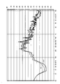
- the body sound measuring device of the embodiment In a state where the body sound measuring device of the embodiment is not in contact with the body surface of the living body in an ideal state (for example, a state in which the accommodation space of the first sound measuring device is incomplete), Nearly the same sound is measured by the sound measuring device and the second sound measuring device. For this reason, the sound intensity measured by the first sound measuring instrument and the sound intensity measured by the second sound measuring instrument are substantially the same at any frequency.
- the biological sound measuring device in contact with the body surface of the living body in an ideal state (for example, a state where the accommodation space of the first sound measuring device is sealed by the body surface),
- the sound intensity measured by the sound measuring instrument and the sound intensity measured by the second sound measuring instrument differ depending on the frequency.
- the first sound measuring device mainly measures lung sounds, and therefore, the intensity of the lung sound frequency is higher than that in the non-optimal state.
- the second sound measuring device is not sealed with the body surface and cannot measure lung sounds. For this reason, among the sounds measured by the second sound measuring device, the intensity of the lung sound is low even in the optimum state.
- the sound intensity of a specific frequency (for example, a frequency selected from the frequency range of lung sounds) measured by the first sound measuring instrument, and the sound intensity of the specific frequency measured by the second sound measuring instrument
- a specific frequency for example, a frequency selected from the frequency range of lung sounds
- the biological sound measuring device of the embodiment uses this to determine the measurement accuracy of lung sound, and when the measurement accuracy is less than a predetermined value, for example, change the method of pressing the device against the body surface. By providing prompting notifications, accurate measurement of lung sounds is supported.
- a predetermined value for example, change the method of pressing the device against the body surface.
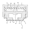
- FIG. 1 is a side view showing a schematic configuration example of a biological sound measuring device 1 which is an embodiment of the biological sound measuring device of the present invention.
- the biological sound measuring device 1 has a main body 1b composed of a housing made of resin or metal, and a head 1a is provided on one end of the main body 1b.
- control unit 4 that performs overall control, a battery 5 that supplies a voltage necessary for operation, and a display unit that displays an image by a liquid crystal display panel or an organic EL (Electro Luminescence) display panel. 6 are provided.
- the control unit 4 includes a CPU (Central Processing Unit), a RAM (Random Access Memory), a ROM (Read Only Memory), and the like, and controls each hardware of the biological sound measurement device 1 according to a program.
- the ROM of the control unit 4 stores a program including a biological sound measurement support program.
- the head unit 1 a is provided with a measurement unit 3 that protrudes to one side (downward in FIG. 1) in a direction substantially orthogonal to the longitudinal direction of the biological sound measurement device 1.
- a pressure receiving portion 3 a that is in contact with the body surface S of the living body that is the subject and receives pressure from the body surface S is provided.
- the biological sound measuring apparatus 1 is configured such that, for example, the index finger of the user's hand Ha is placed on the back surface of the measurement unit 3 in the head unit 1a, and the pressure receiving unit 3a of the measurement unit 3 is pressed against the body surface S by the index finger. used.
- FIG. 2 is a schematic sectional view taken along the line AA in the biological sound measuring device 1 shown in FIG.
- the measurement unit 3 includes a first sound measuring device M1 that measures sound, a first housing 31 that forms an accommodating space SP1 that accommodates the first sound measuring device M1 and has an opening 31h, and an opening 31h that accommodates the opening 31h.
- a housing cover 32 that closes from the outside of SP1 and covers the first housing 31, a second sound measuring device M2 that measures sound, and an accommodation space SP2 that accommodates the second sound measuring device M2 are formed and an opening 34h is formed.
- a second housing 34 is formed.
- the measurement unit 3 is fixed to the housing 2 by being fitted into an opening formed in the housing 2 constituting the head portion 1a in a state where a part of the housing cover 32 is exposed.
- the tip of the exposed portion of the housing cover 32 from the housing 2 is a flat surface, and this flat surface constitutes the pressure receiving portion 3a in FIG.
- the housing 2 is made of a resin that can transmit sound.
- the first sound measuring device M1 is for measuring a lung sound to be measured by the biological sound measuring device 1, and is, for example, wider than a frequency range of the lung sound (generally 10 Hz to 1 kHz). It is configured by a MEMS (Micro Electro Mechanical Systems) type microphone or a capacitance type microphone that measures sound in a band (for example, a frequency range of 10 Hz to 10 kHz).
- a MEMS Micro Electro Mechanical Systems
- capacitance type microphone that measures sound in a band (for example, a frequency range of 10 Hz to 10 kHz).
- the first sound measuring device M1 is electrically connected to the control unit 4 shown in FIG. 1 by a lead wire (not shown) and transmits the information of the measured sound to the control unit 4.
- the pressure receiving portion 3a of the housing cover 32 is in contact with the body surface S, and the accommodation space SP1 is sealed by the body surface S by the pressure from the body surface S (hereinafter, this state) Is called a contact state).
- the pressure receiving part 3a vibrates by the lung sound transmitted from the living body to the body surface S
- the internal pressure of the accommodation space SP1 fluctuates due to this vibration, and the electric signal corresponding to the lung sound is generated by the fluctuation of the internal pressure. Will be measured by M1.
- the first housing 31 has a substantially convex shape downward in FIG. 2, and is made of a material having higher acoustic impedance and higher rigidity than air such as resin or metal. In the contact state, the first housing 31 reflects the sound in the measurement frequency band of the first sound measuring device M1 and the second sound measuring device M2 so that sound is not transmitted from the outside into the accommodation space SP1. Consists of materials.
- the housing cover 32 is a bottomed cylindrical member, and the shape of the hollow portion substantially matches the outer wall shape of the first housing 31.
- the housing cover 32 is made of a material having acoustic impedance that is close to that of the human body, air, or water and has good biocompatibility.
- a material of the housing cover 32 for example, silicon or elastomer is used.
- the second sound measuring device M2 measures sound generated around the biological sound measuring device 1 (environmental sound such as a human voice or rubbing sound between the main body 1b and the living body or clothes).
- the biological sound measuring device 1 is composed of a MEMS microphone or a capacitance microphone that measures sound in a wider band (for example, a frequency range of 10 Hz to 10 kHz) than the frequency range of lung sounds.
- the second sound measuring device M2 is electrically connected to the control unit 4 shown in FIG. 1 through a lead wire (not shown) and transmits the information of the measured sound to the control unit 4.
- the second sound measuring device M2 is fixed to the surface of the first housing 31 opposite to the pressure receiving portion 3a side.
- the periphery of the second sound measuring device M2 is covered with a second housing 34.
- the second housing 34 is made of a material (for example, resin) that allows sound generated around the biological sound measuring device 1 to enter the accommodation space SP2 that accommodates the second sound measuring device M2.
- the second housing 34 has an opening 34h. For this reason, the sound generated around the biological sound measuring device 1 can easily enter from the opening 34h.
- the second sound measuring device M2 is provided in the measurement unit 3 in the example of FIG. 2, it is only necessary to be able to measure sound generated around the biological sound measuring device 1, and the installation location is particularly limited. It is not a thing.
- the 2nd sound measuring device M2 may be provided in the main body part 1b other than the head part 1a at a place where the user is unlikely to touch during use.
- the control unit 4 shown in FIG. 1 uses the first sound measured by the first sound measuring device M1 and the intensity of the second sound measured by the second sound measuring device M2 at a predetermined specific frequency. Based on the difference, the measurement accuracy of the lung sound by the first sound measuring device M1 is determined.
- a frequency at which the intensity of the sound detected by the first sound measuring device M1 in the contact state becomes significantly higher or lower than that in the non-contact state is used.
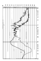
- FIG. 3 is a diagram showing a Fourier transform result of the sound measured by the first sound measuring device M1 and the second sound measuring device M2 in the contact state of the biological sound measuring device 1 shown in FIG.
- FIG. 4 is a diagram showing a Fourier transform result of the sound measured by the first sound measuring device M1 and the second sound measuring device M2 in the non-contact state of the biological sound measuring device 1 shown in FIG.
- FIGS. 3 and 4 show a graph m1 obtained by Fourier transform of the first sound measured by the first sound measuring device M1, and a second sound measured by the second sound measuring device M2.
- a graph m2 obtained by Fourier transform is shown.
- the horizontal axis in FIGS. 3 and 4 indicates the frequency in logarithm.
- the lung sound is transmitted to the accommodation space SP1 of the first sound measuring device M1, and the lung sound is not transmitted to the accommodation space SP2. Therefore, as shown in FIG. 3, in the frequency range of 20 Hz to 200 Hz, the sound intensity measured by the first sound measuring instrument M1 and the sound intensity measured by the second sound measuring instrument M2 The difference between
- the intensity of the sound in the frequency range of 20 Hz or more and 200 Hz or less detected by the first sound measuring device M1 is significantly high in the contact state. 3 and 4, the sound intensity measured by the first sound measuring instrument M1 and the sound intensity measured by the second sound measuring instrument M2 in the frequency range below 20 Hz. The difference is getting smaller.
- this is an example, and in a contact state, the intensity of sound in a low frequency region (for example, 10 Hz to 200 Hz) that is difficult to be generated outside the accommodation space SP1 in the frequency region of lung sound is significantly increased.
- an arbitrary frequency for example, 50 Hz, 100 Hz, etc.
- a frequency range of 10 Hz to 200 Hz can be set as the specific frequency.
- the intrusion of sound from the outside is extremely reduced with respect to the accommodation space SP1 of the first sound measuring device M1. Therefore, as shown in FIG. 3, the sound intensity measured by the first sound measuring device M1 and the second sound measuring device in a frequency range higher than 1 kHz and higher than 7 kHz higher than the frequency range of lung sound. The difference from the sound intensity measured by M2 increases.
- the intensity of the sound in the frequency range greater than 1 kHz and less than or equal to 7 kHz detected by the first sound measuring device M1 is significantly reduced in the contact state.
- an arbitrary frequency for example, 1.5 kHz, 2 kHz, etc.
- a frequency range greater than 1 kHz and less than or equal to 7 kHz can be set as the specific frequency.
- the specific frequency when the specific frequency is set in this way, in the contact state, the specific frequency of the first sound measured by the first sound measuring device M1 and the second sound measured by the second sound measuring device M2.
- the difference in intensity at is significantly greater than when it is not in a contact state (a state in which substantially the same sound is measured by the first sound measuring device M1 and the second sound measuring device M2).
- control unit 4 measures the first sound when the absolute value of the difference between the intensity at the specific frequency of the first sound and the intensity at the specific frequency of the second sound is less than a predetermined threshold. It is determined that the accuracy is less than a predetermined value, and when the absolute value is greater than or equal to the threshold, it is determined that the measurement accuracy of the first sound is greater than or equal to the predetermined value.
- control unit 4 performs notification when it is determined that the measurement accuracy is less than a predetermined value. For example, the control unit 4 performs notification by causing the display unit 6 to display a message that prompts the user to change the manner in which the pressure receiving unit 3a is pressed against the body surface S. The control part 4 may alert
- the biological sound measurement device 1 and, for example, a smartphone may be configured to be connectable, and a message display or voice output may be performed using a smartphone display or speaker.
- a message is output, but it is not limited to this.
- an LED Light Emitting Diode
- the control unit 4 emits the LED in blue, for example, when the measurement accuracy is determined to be equal to or higher than a predetermined value.
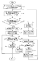
- FIG. 5 is a flowchart for explaining an operation example of the biological sound measuring device 1 shown in FIG.
- the control unit 4 starts sound measurement by the first sound measuring device M1 and the second sound measuring device M2 (step S1). Information on the sound measured by the first sound measuring device M1 and the second sound measuring device M2 is stored in the RAM of the control unit 4.
- control unit 4 When a certain time has elapsed, the control unit 4 performs a Fourier transform on the first sound and the second sound for a certain time stored in the RAM (step S2).
- control unit 4 obtains the absolute value of the difference between the intensity of the specific frequency of the first sound obtained by the Fourier transform and the intensity of the specific frequency of the second sound obtained by the Fourier transform. Then, it is determined whether or not the absolute value is greater than or equal to a predetermined threshold value TH1 (step S3).
- the threshold value TH1 is, for example, the intensity of each frequency in the range from 20 Hz to 200 Hz in the graph m1 shown in FIG. 4 and each frequency in the range from 20 Hz to 200 Hz in the graph m2 shown in FIG.
- the largest value of the differences from the intensity or the average value of the differences is set.
- the threshold value TH1 is, for example, the intensity of each frequency in the range greater than 1 kHz and less than or equal to 7 kHz in the graph m1 illustrated in FIG. 4, and each of the ranges greater than 1 kHz and less than or equal to 7 kHz in the graph m2 illustrated in FIG.
- the largest value of the differences from the intensity of the frequency or the average value of the differences is set.
- step S3 NO
- the control unit 4 determines that the sound measurement accuracy by the first sound measuring device M1 is low (less than a predetermined value). (Step S4).
- step S4 the control unit 4 performs notification for urging to change the pressing method of the pressure receiving unit 3a (step S5).
- step S5 the process returns to step S2, and the process of step S2 is performed when the sound for a predetermined time is measured again.
- step S3 When the absolute value is equal to or greater than the threshold value TH1 (step S3: YES), the control unit 4 determines that the sound measurement accuracy by the first sound measuring instrument M1 is high (greater than or equal to a predetermined value). (Step S6).
- step S6 the control unit 4 starts counting up the count value of the built-in measurement timer and starts a process for determining the presence or absence of wheezing (step S7).
- control unit 4 uses the second sound measured by the second sound measuring device M2 as the noise other than the lung sound mixed in the first sound measured by the first sound measuring device M1. Remove based on. Then, the control unit 4 determines that “wheezing is present” when the first sound after the noise removal becomes, for example, an intensity that can be determined as wheezing.
- control unit 4 determines whether or not the count value of the measurement timer has reached a predetermined time required for determining the presence or absence of wheezing. Is determined (step S8).
- step S8 NO
- the control unit 4 performs step S2 based on the sound data accumulated in the RAM since the previous measurement accuracy determination. Then, the measurement accuracy determination process described in step S3, step S4, and step S6 is executed (step S9).
- step S9 when the measurement accuracy is less than the predetermined value (step S10: NO), the control unit 4 temporarily stops the counting up of the measurement timer (step S11), and then the pressure receiving unit. A notification for prompting the change of the pressing method of 3a is performed (step S12). After step S12, the process returns to step S9.
- step S10 If the measurement accuracy is equal to or higher than the predetermined value as a result of the determination process in step S9 (step S10: YES), the control unit 4 restarts the count up of the measurement timer (step S13). Note that the process of step S13 is executed only when the process of step S11 is performed after the determination of step S8 is NO. After step S13, the process returns to step S8.
- step S8 when the count value reaches a predetermined time (step S8: YES), the control unit 4 ends the determination process for the presence or absence of wheezing, and displays the determination result on, for example, the display unit 6 ( Step S14), the measurement ends.
- the second sound measuring device M2 does not need to be provided in the vicinity of the pressure receiving portion 3a, the structure in the vicinity of the pressure receiving portion 3a can be prevented from becoming complicated and large.
- the second sound measuring device M2 is not restricted such as being housed in a sealed state, it does not hinder downsizing of the device.
- the second sound measuring device M2 can also be used for noise removal at the time of lung sound measurement, compared to the case where a dedicated sound measuring device is provided for determination of measurement accuracy, the manufacture of the device is performed. An increase in cost can be prevented.
- the second sound measuring device M2 is used for noise removal in the above example, but may be provided only for determination of measurement accuracy.
- the body sound measuring device 1 since the determination process of the presence or absence of wheezing is started when the control unit 4 determines that the measurement accuracy is high, the presence or absence of wheezing can be determined with high accuracy. .
- the notification is performed again. For this reason, the user can return to a state where measurement accuracy is high by changing the pressing method of the apparatus according to the notification.
- the determination process for the presence or absence of wheezing is temporarily stopped, and this determination process is resumed when the measurement accuracy is restored. For this reason, it is not necessary to redo the determination process for the presence or absence of wheezing, and the time until the determination result for the presence or absence of wheezing is output can be shortened.
- step S3 in FIG. 5 the measurement accuracy is determined with one specific frequency, but a plurality of specific frequencies may be set.
- an arbitrary frequency selected from a frequency range of 10 Hz to 200 Hz (for example, 100 Hz) and an arbitrary frequency selected from a frequency range of greater than 1 kHz to 7 kHz (for example, 2 kHz) are specified as above. It can also be set as a frequency.
- the threshold value TH1 to be compared with a specific frequency selected from a frequency range of 10 Hz to 200 Hz is, for example, each of the ranges of 20 Hz to 200 Hz in the graph m1 shown in FIG.
- the largest value among the differences between the intensity of the frequency and the intensity of each frequency in the range of 20 Hz to 200 Hz in the graph m2 shown in FIG. 4, or the average value of this difference is set.
- the threshold value TH1 to be compared with a specific frequency selected from a frequency range greater than 1 kHz and less than or equal to 7 kHz is, for example, the intensity of each frequency in the range greater than 1 kHz and less than or equal to 7 kHz in the graph m1 shown in FIG.
- the largest value of the differences from the intensities of the respective frequencies in the range of 1 kHz to 7 kHz in the graph m2 shown, or the average value of this difference is set.
- the threshold value TH1 compared with each of the two specific frequencies may be set to a different value.
- step S3 of FIG. 5 the control unit 4 determines that the difference in intensity between the first sound and the second sound at each of the two specific frequencies is equal to or greater than the threshold TH1. If so, it is determined in step S6 that the measurement accuracy is high. In addition, when the difference in intensity between the first sound and the second sound at one of the two specific frequencies is less than the threshold value TH1, the control unit 4 has low measurement accuracy in step S4. Is determined.
- the first sound measuring device M1 is used for measuring lung sounds as biological sounds, but may be used for measuring heart sounds as biological sounds, for example. .
Landscapes
- Health & Medical Sciences (AREA)
- Physics & Mathematics (AREA)
- Engineering & Computer Science (AREA)
- Life Sciences & Earth Sciences (AREA)
- Acoustics & Sound (AREA)
- General Health & Medical Sciences (AREA)
- Public Health (AREA)
- Animal Behavior & Ethology (AREA)
- Heart & Thoracic Surgery (AREA)
- Veterinary Medicine (AREA)
- Surgery (AREA)
- Molecular Biology (AREA)
- Medical Informatics (AREA)
- Biomedical Technology (AREA)
- Computational Linguistics (AREA)
- Human Computer Interaction (AREA)
- Multimedia (AREA)
- Signal Processing (AREA)
- Epidemiology (AREA)
- Audiology, Speech & Language Pathology (AREA)
- Business, Economics & Management (AREA)
- Emergency Management (AREA)
- General Physics & Mathematics (AREA)
- Pulmonology (AREA)
- Measurement Of The Respiration, Hearing Ability, Form, And Blood Characteristics Of Living Organisms (AREA)
- Ultra Sonic Daignosis Equipment (AREA)
- Measuring Pulse, Heart Rate, Blood Pressure Or Blood Flow (AREA)
Priority Applications (3)
| Application Number | Priority Date | Filing Date | Title |
|---|---|---|---|
| CN201980025622.0A CN112040871A (zh) | 2018-04-13 | 2019-04-10 | 生物声音测定装置、生物声音测定辅助方法和程序 |
| DE112019001940.6T DE112019001940T5 (de) | 2018-04-13 | 2019-04-10 | Biologische Geräuschmessungsvorrichtung, biologisches Geräuschmessungs-Unterstützungsverfahren und biologisches Geräuschmessungs-Unterstützungsprogramm |
| US17/060,167 US11278258B2 (en) | 2018-04-13 | 2020-10-01 | Biological sound measuring device, biological sound measurement support method, and biological sound measurement support program |
Applications Claiming Priority (2)
| Application Number | Priority Date | Filing Date | Title |
|---|---|---|---|
| JP2018078018A JP7006473B2 (ja) | 2018-04-13 | 2018-04-13 | 生体音測定装置、生体音測定支援方法、生体音測定支援プログラム |
| JP2018-078018 | 2018-04-13 |
Related Child Applications (1)
| Application Number | Title | Priority Date | Filing Date |
|---|---|---|---|
| US17/060,167 Continuation US11278258B2 (en) | 2018-04-13 | 2020-10-01 | Biological sound measuring device, biological sound measurement support method, and biological sound measurement support program |
Publications (1)
| Publication Number | Publication Date |
|---|---|
| WO2019198770A1 true WO2019198770A1 (ja) | 2019-10-17 |
Family
ID=68163270
Family Applications (1)
| Application Number | Title | Priority Date | Filing Date |
|---|---|---|---|
| PCT/JP2019/015676 WO2019198770A1 (ja) | 2018-04-13 | 2019-04-10 | 生体音測定装置、生体音測定支援方法、生体音測定支援プログラム |
Country Status (5)
| Country | Link |
|---|---|
| US (1) | US11278258B2 (de) |
| JP (1) | JP7006473B2 (de) |
| CN (1) | CN112040871A (de) |
| DE (1) | DE112019001940T5 (de) |
| WO (1) | WO2019198770A1 (de) |
Families Citing this family (2)
| Publication number | Priority date | Publication date | Assignee | Title |
|---|---|---|---|---|
| JP7183564B2 (ja) * | 2018-04-18 | 2022-12-06 | オムロンヘルスケア株式会社 | 生体音測定装置、生体音測定装置の作動方法、生体音測定装置の作動プログラム |
| US11232570B2 (en) | 2020-02-13 | 2022-01-25 | Olympus Corporation | System and method for diagnosing severity of gastritis |
Citations (5)
| Publication number | Priority date | Publication date | Assignee | Title |
|---|---|---|---|---|
| JP2000060847A (ja) * | 1998-08-24 | 2000-02-29 | Nippon Colin Co Ltd | 生体音検出装置 |
| US20070013509A1 (en) * | 2003-03-13 | 2007-01-18 | Sridhar Lakshmanan | Living being presence detection system |
| JP2011505997A (ja) * | 2007-12-20 | 2011-03-03 | アカリクス アクティーゼルスカブ | 音響信号を測定するための接着式パッチ |
| WO2011114669A1 (ja) * | 2010-03-18 | 2011-09-22 | パナソニック株式会社 | 生体音検査装置 |
| JP2015020030A (ja) * | 2013-07-23 | 2015-02-02 | シャープ株式会社 | 生体音収集装置 |
Family Cites Families (19)
| Publication number | Priority date | Publication date | Assignee | Title |
|---|---|---|---|---|
| KR950703891A (ko) * | 1992-12-07 | 1995-11-17 | 안드레드 빌러스 | 전자청진기 |
| US5812678A (en) * | 1996-02-26 | 1998-09-22 | Scalise; Stanley J. | Auscultation augmentation device |
| AU3052899A (en) * | 1998-04-08 | 1999-11-01 | Karmel Medical Acoustic Technologies Ltd. | Determination of apnea type |
| US8275140B2 (en) * | 1999-10-28 | 2012-09-25 | Clive Leonard Smith | Transducer for sensing actual or simulated body sounds |
| US7940937B2 (en) * | 1999-10-28 | 2011-05-10 | Clive Smith | Transducer for sensing body sounds |
| US20040032957A1 (en) * | 2002-08-14 | 2004-02-19 | Mansy Hansen A. | Sensors and sensor assemblies for monitoring biological sounds and electric potentials |
| US8920343B2 (en) * | 2006-03-23 | 2014-12-30 | Michael Edward Sabatino | Apparatus for acquiring and processing of physiological auditory signals |
| US20080013747A1 (en) * | 2006-06-30 | 2008-01-17 | Bao Tran | Digital stethoscope and monitoring instrument |
| JP5701533B2 (ja) | 2010-07-26 | 2015-04-15 | シャープ株式会社 | 測定位置判定装置、測定位置判定方法、制御プログラムおよび記録媒体 |
| US20130131465A1 (en) | 2010-07-26 | 2013-05-23 | Sharp Kabushiki Kaisha | Biomeasurement device, biomeasurement method, control program for a biomeasurement device, and recording medium with said control program recorded thereon |
| TWI528944B (zh) * | 2011-08-11 | 2016-04-11 | Nat Univ Tsing Hua | 應用於電子聽診器的疾病診斷方法 |
| US9848848B2 (en) * | 2014-06-30 | 2017-12-26 | The Johns Hopkins University | Lung sound denoising stethoscope, algorithm, and related methods |
| TW201618720A (zh) * | 2014-11-20 | 2016-06-01 | 創心醫電股份有限公司 | 採集臟器聲的方法及其系統與臟器聲錄音器 |
| US9770224B2 (en) * | 2015-09-20 | 2017-09-26 | Hummingdoc, Llc | Stethoscope adapter system for a headset microphone |
| JP6606965B2 (ja) | 2015-10-14 | 2019-11-20 | Tdk株式会社 | 呼吸計測装置、呼吸計測方法及びプログラム |
| US10765399B2 (en) * | 2015-10-30 | 2020-09-08 | The Johns Hopkins University | Programmable electronic stethoscope devices, algorithms, systems, and methods |
| US10231691B2 (en) * | 2016-09-09 | 2019-03-19 | Mustafa Behnan Sahin | Audible ultrasound physical examination device |
| JP2018102849A (ja) | 2016-12-28 | 2018-07-05 | オムロンヘルスケア株式会社 | 生体音測定装置 |
| JP7081409B2 (ja) * | 2018-09-12 | 2022-06-07 | オムロンヘルスケア株式会社 | 喘鳴検出装置、喘鳴検出方法、及び喘鳴検出プログラム |
-
2018
- 2018-04-13 JP JP2018078018A patent/JP7006473B2/ja active Active
-
2019
- 2019-04-10 DE DE112019001940.6T patent/DE112019001940T5/de active Pending
- 2019-04-10 CN CN201980025622.0A patent/CN112040871A/zh active Pending
- 2019-04-10 WO PCT/JP2019/015676 patent/WO2019198770A1/ja active Application Filing
-
2020
- 2020-10-01 US US17/060,167 patent/US11278258B2/en active Active
Patent Citations (5)
| Publication number | Priority date | Publication date | Assignee | Title |
|---|---|---|---|---|
| JP2000060847A (ja) * | 1998-08-24 | 2000-02-29 | Nippon Colin Co Ltd | 生体音検出装置 |
| US20070013509A1 (en) * | 2003-03-13 | 2007-01-18 | Sridhar Lakshmanan | Living being presence detection system |
| JP2011505997A (ja) * | 2007-12-20 | 2011-03-03 | アカリクス アクティーゼルスカブ | 音響信号を測定するための接着式パッチ |
| WO2011114669A1 (ja) * | 2010-03-18 | 2011-09-22 | パナソニック株式会社 | 生体音検査装置 |
| JP2015020030A (ja) * | 2013-07-23 | 2015-02-02 | シャープ株式会社 | 生体音収集装置 |
Also Published As
| Publication number | Publication date |
|---|---|
| DE112019001940T5 (de) | 2021-01-07 |
| US20210015443A1 (en) | 2021-01-21 |
| JP2019180988A (ja) | 2019-10-24 |
| JP7006473B2 (ja) | 2022-01-24 |
| US11278258B2 (en) | 2022-03-22 |
| CN112040871A (zh) | 2020-12-04 |
Similar Documents
| Publication | Publication Date | Title |
|---|---|---|
| WO2019198770A1 (ja) | 生体音測定装置、生体音測定支援方法、生体音測定支援プログラム | |
| US20210077056A1 (en) | Wheezing detection device and wheezing detection program | |
| US20210196226A1 (en) | Wheeze detection apparatus, wheeze detection method, and wheeze detection program | |
| US20210330278A1 (en) | Biological sound measurement device | |
| US20210015445A1 (en) | Biological sound measuring device, method for operating biological sound measuring device, and program for operating biological sound measuring device | |
| WO2021192862A1 (ja) | 喘鳴検出装置 | |
| WO2019203097A1 (ja) | 生体音測定装置、生体音測定支援方法、生体音測定支援プログラム | |
| WO2021192863A1 (ja) | 喘鳴検出装置 | |
| WO2020162105A1 (ja) | 生体音測定装置、生体音測定装置の制御方法、生体音測定装置の制御プログラム | |
| WO2020145059A1 (ja) | 生体音測定装置 | |
| WO2020145058A1 (ja) | 生体音測定装置 | |
| WO2022050002A1 (ja) | 呼吸音情報処理システム及び呼吸音測定装置 | |
| WO2020145060A1 (ja) | 生体音測定装置 | |
| US20210330282A1 (en) | Biological sound measurement device | |
| JP6621461B2 (ja) | 警報器 | |
| RU121979U1 (ru) | Электроакустический преобразователь | |
| JP2015022586A (ja) | 警報器 | |
| KR20160023016A (ko) | 일회용 진동표시기 |
Legal Events
| Date | Code | Title | Description |
|---|---|---|---|
| 121 | Ep: the epo has been informed by wipo that ep was designated in this application |
Ref document number: 19784863 Country of ref document: EP Kind code of ref document: A1 |
|
| 122 | Ep: pct application non-entry in european phase |
Ref document number: 19784863 Country of ref document: EP Kind code of ref document: A1 |