WO2019189347A1 - 粉末床溶融結合造形物及びその作製方法 - Google Patents
粉末床溶融結合造形物及びその作製方法 Download PDFInfo
- Publication number
- WO2019189347A1 WO2019189347A1 PCT/JP2019/013161 JP2019013161W WO2019189347A1 WO 2019189347 A1 WO2019189347 A1 WO 2019189347A1 JP 2019013161 W JP2019013161 W JP 2019013161W WO 2019189347 A1 WO2019189347 A1 WO 2019189347A1
- Authority
- WO
- WIPO (PCT)
- Prior art keywords
- layer
- solidified
- resin powder
- modeling
- laser beam
- Prior art date
Links
Images


Classifications
-
- B—PERFORMING OPERATIONS; TRANSPORTING
- B33—ADDITIVE MANUFACTURING TECHNOLOGY
- B33Y—ADDITIVE MANUFACTURING, i.e. MANUFACTURING OF THREE-DIMENSIONAL [3-D] OBJECTS BY ADDITIVE DEPOSITION, ADDITIVE AGGLOMERATION OR ADDITIVE LAYERING, e.g. BY 3-D PRINTING, STEREOLITHOGRAPHY OR SELECTIVE LASER SINTERING
- B33Y40/00—Auxiliary operations or equipment, e.g. for material handling
- B33Y40/20—Post-treatment, e.g. curing, coating or polishing
-
- B—PERFORMING OPERATIONS; TRANSPORTING
- B22—CASTING; POWDER METALLURGY
- B22F—WORKING METALLIC POWDER; MANUFACTURE OF ARTICLES FROM METALLIC POWDER; MAKING METALLIC POWDER; APPARATUS OR DEVICES SPECIALLY ADAPTED FOR METALLIC POWDER
- B22F10/00—Additive manufacturing of workpieces or articles from metallic powder
- B22F10/20—Direct sintering or melting
- B22F10/28—Powder bed fusion, e.g. selective laser melting [SLM] or electron beam melting [EBM]
-
- B—PERFORMING OPERATIONS; TRANSPORTING
- B22—CASTING; POWDER METALLURGY
- B22F—WORKING METALLIC POWDER; MANUFACTURE OF ARTICLES FROM METALLIC POWDER; MAKING METALLIC POWDER; APPARATUS OR DEVICES SPECIALLY ADAPTED FOR METALLIC POWDER
- B22F10/00—Additive manufacturing of workpieces or articles from metallic powder
- B22F10/30—Process control
- B22F10/38—Process control to achieve specific product aspects, e.g. surface smoothness, density, porosity or hollow structures
-
- B—PERFORMING OPERATIONS; TRANSPORTING
- B29—WORKING OF PLASTICS; WORKING OF SUBSTANCES IN A PLASTIC STATE IN GENERAL
- B29C—SHAPING OR JOINING OF PLASTICS; SHAPING OF MATERIAL IN A PLASTIC STATE, NOT OTHERWISE PROVIDED FOR; AFTER-TREATMENT OF THE SHAPED PRODUCTS, e.g. REPAIRING
- B29C64/00—Additive manufacturing, i.e. manufacturing of three-dimensional [3D] objects by additive deposition, additive agglomeration or additive layering, e.g. by 3D printing, stereolithography or selective laser sintering
- B29C64/10—Processes of additive manufacturing
- B29C64/141—Processes of additive manufacturing using only solid materials
- B29C64/153—Processes of additive manufacturing using only solid materials using layers of powder being selectively joined, e.g. by selective laser sintering or melting
-
- B—PERFORMING OPERATIONS; TRANSPORTING
- B29—WORKING OF PLASTICS; WORKING OF SUBSTANCES IN A PLASTIC STATE IN GENERAL
- B29C—SHAPING OR JOINING OF PLASTICS; SHAPING OF MATERIAL IN A PLASTIC STATE, NOT OTHERWISE PROVIDED FOR; AFTER-TREATMENT OF THE SHAPED PRODUCTS, e.g. REPAIRING
- B29C64/00—Additive manufacturing, i.e. manufacturing of three-dimensional [3D] objects by additive deposition, additive agglomeration or additive layering, e.g. by 3D printing, stereolithography or selective laser sintering
- B29C64/20—Apparatus for additive manufacturing; Details thereof or accessories therefor
- B29C64/264—Arrangements for irradiation
- B29C64/268—Arrangements for irradiation using laser beams; using electron beams [EB]
-
- B—PERFORMING OPERATIONS; TRANSPORTING
- B29—WORKING OF PLASTICS; WORKING OF SUBSTANCES IN A PLASTIC STATE IN GENERAL
- B29C—SHAPING OR JOINING OF PLASTICS; SHAPING OF MATERIAL IN A PLASTIC STATE, NOT OTHERWISE PROVIDED FOR; AFTER-TREATMENT OF THE SHAPED PRODUCTS, e.g. REPAIRING
- B29C64/00—Additive manufacturing, i.e. manufacturing of three-dimensional [3D] objects by additive deposition, additive agglomeration or additive layering, e.g. by 3D printing, stereolithography or selective laser sintering
- B29C64/30—Auxiliary operations or equipment
- B29C64/307—Handling of material to be used in additive manufacturing
- B29C64/314—Preparation
-
- B—PERFORMING OPERATIONS; TRANSPORTING
- B33—ADDITIVE MANUFACTURING TECHNOLOGY
- B33Y—ADDITIVE MANUFACTURING, i.e. MANUFACTURING OF THREE-DIMENSIONAL [3-D] OBJECTS BY ADDITIVE DEPOSITION, ADDITIVE AGGLOMERATION OR ADDITIVE LAYERING, e.g. BY 3-D PRINTING, STEREOLITHOGRAPHY OR SELECTIVE LASER SINTERING
- B33Y10/00—Processes of additive manufacturing
-
- B—PERFORMING OPERATIONS; TRANSPORTING
- B33—ADDITIVE MANUFACTURING TECHNOLOGY
- B33Y—ADDITIVE MANUFACTURING, i.e. MANUFACTURING OF THREE-DIMENSIONAL [3-D] OBJECTS BY ADDITIVE DEPOSITION, ADDITIVE AGGLOMERATION OR ADDITIVE LAYERING, e.g. BY 3-D PRINTING, STEREOLITHOGRAPHY OR SELECTIVE LASER SINTERING
- B33Y30/00—Apparatus for additive manufacturing; Details thereof or accessories therefor
-
- Y—GENERAL TAGGING OF NEW TECHNOLOGICAL DEVELOPMENTS; GENERAL TAGGING OF CROSS-SECTIONAL TECHNOLOGIES SPANNING OVER SEVERAL SECTIONS OF THE IPC; TECHNICAL SUBJECTS COVERED BY FORMER USPC CROSS-REFERENCE ART COLLECTIONS [XRACs] AND DIGESTS
- Y02—TECHNOLOGIES OR APPLICATIONS FOR MITIGATION OR ADAPTATION AGAINST CLIMATE CHANGE
- Y02P—CLIMATE CHANGE MITIGATION TECHNOLOGIES IN THE PRODUCTION OR PROCESSING OF GOODS
- Y02P10/00—Technologies related to metal processing
- Y02P10/25—Process efficiency
Definitions
- the present invention relates to a powder bed fusion bonded model and a method for manufacturing the same.
- Such a modeling apparatus includes an optical modeling apparatus and a powder bed fusion bonding apparatus.
- the powder bed fusion bonding apparatus stores a powder material in a storage container.
- the powder material is transported from the storage container to the production container by the recoater, and a thin layer of the powder material is formed on the modeling table in the production container.
- the powder material in this region is melt-bonded and solidified to form a solidified layer.
- the solidified layer is laminated on the modeling table to produce a three-dimensional structure.
- Examples of powder materials used in the production of a model include resin powder, metal powder, ceramic powder, and mixed powders thereof.
- the molded object When a molded object is produced with a powder bed fusion bonding apparatus using resin powder, the molded object produces a mold as compared with a molded article produced with an injection molding apparatus using the same type of resin. Although it can be produced in a short period of time because it is not necessary, the strength is lowered because no pressure is applied during production.
- a solidified layer of a resin bed in which n (n is an integer greater than or equal to 3) layers of a solidified resin layer is formed The solidified layer of the first layer is melted and solidified with a first energy, and each of the solidified layers of the second layer to the (n-1) th layer is formed from at least one of the solidified layers adjacent in the vertical direction.
- the protruding portion that protrudes outward, and the overlapping portion that is at least as thick as the thickness of the solidified layer inside the protruding portion that overlaps the adjacent solidified layer is melted and solidified by the first energy
- the protruding portion and A powder bed fusion bonding model in which a central portion inside the overlapping portion is melted and solidified by a second energy lower than the first energy, and the solidified layer of the nth layer is melted and solidified by the first energy. Things are provided.
- a step of forming a layer of the resin powder and after forming the layer of the resin powder, irradiating a modeling region of the layer of the resin powder with laser light,
- the resin powder is melt-bonded, solidified, and a step of forming a solidified layer is repeated to form an n (n is an integer of 3 or more) layer of the resin powder, and the resin of the n layer
- n is an integer of 3 or more
- the laser beam is irradiated with the first energy from the bottom to the modeling region of the first layer of the resin powder, and the second layer to the (n ⁇ 1) th layer.
- the resin powder adjacent vertically in the modeling region of each layer of the resin powder A protruding portion that protrudes outward from at least one of the modeling regions of the layer, and at least the thickness of the resin powder layer inside the protruding portion that overlaps the modeling region of the adjacent resin powder layer
- the laser beam is irradiated to the overlapping portion of the width with the first energy, and the laser beam is irradiated to the center portion inside the protruding portion and the overlapping portion with a second energy lower than the first energy.
- a laser beam is irradiated with a first energy to a modeling region of the first resin powder layer from the bottom among the n resin powder layers, and the second layer Thru
- the laser beam is irradiated with the first energy to at least the overlapping portion having a width corresponding to the thickness of the resin powder layer inside the protruding portion that overlaps the modeling region of the layer, and the laser is applied to the protruding portion and the central portion inside the overlapping portion.
- the light is irradiated with the second energy lower than the first energy, and the laser light is irradiated with the first energy to the modeling region of the nth resin powder layer.
- the modeling region of the first layer of the resin powder, the protruding portion and the overlapping portion of the modeling regions of the second to (n-1) th resin powder layers, and the nth layer can be firmly melt-bonded.
- the surface of the first solidified layer exposed to the atmosphere, the protruding portion of the surface of each of the second to n ⁇ 1th solidified layers, and the nth layer Open pores formed on the entire surface of the solidified layer, that is, the entire surface of the powder bed fusion bonded model is formed when the entire modeling region of the n-layer resin powder layer is irradiated with laser light with the second energy.
- the number of open pores can be reduced.
- the overlapped portion becomes a room for the protruding portion, and the end of the protruding portion at the center side of the surface of each of the second layer to the (n-1) th solidified layer that may be exposed to the atmosphere. It is possible to suppress the formation of open pores in the portion.
- FIG. 1 is a cross-sectional view showing an example of the structure of a shaped article produced using a powder bed fusion bonding apparatus using resin powder.
- FIG. 2 is a diagram for explaining an example of the configuration of the powder bed fusion bonding apparatus according to the present embodiment.
- FIG. 3A is a top view showing a configuration other than the casing of the powder bed fusion bonding apparatus, and
- FIG. 3B is a cross-sectional view taken along the line II in FIG.
- FIG. 4 is a block diagram illustrating the configuration of the laser beam emitting unit.
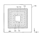
- FIG. 5 is a diagram illustrating an example of a configuration of slice data of the first layer (lowermost layer) from the bottom of the modeled object when the modeled object to be manufactured is divided into four layers.
- FIG. 6 is a diagram illustrating an example of the configuration of slice data of the second layer (intermediate layer) from the bottom of the modeled object when the modeled object to be manufactured is divided into four layers.
- FIG. 7 is a diagram illustrating an example of the configuration of slice data of the third layer (intermediate layer) from the bottom of the modeled object when the modeled object to be manufactured is divided into four layers.
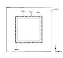
- FIG. 8 is a diagram illustrating an example of a configuration of slice data of the fourth layer (uppermost layer) from the bottom of the modeled object when the modeled object to be manufactured is divided into four layers.
- FIGS. 9A and 9B are diagrams illustrating a zigzag scanning method as an example of a laser beam scanning method.
- FIG. 9A and 9B are diagrams illustrating a zigzag scanning method as an example of a laser beam scanning method.
- FIG. 10 is a cross-sectional view (part 1) in the middle of the formation of the buffer layer of the powder material.
- FIG. 11 is a sectional view (No. 2) in the middle of forming the buffer layer of the powder material.
- FIG. 12 is a sectional view (No. 3) in the middle of forming the buffer layer of the powder material.
- FIG. 13 is a sectional view (No. 4) in the middle of the formation of the buffer layer of the powder material.
- FIG. 14 is a cross-sectional view (No. 1) in the middle of the fabrication of the shaped object.
- FIG. 15 is a cross-sectional view (No. 2) in the middle of the fabrication of the shaped object.
- FIG. 16 is sectional drawing (the 3) in the middle of preparation of a molded article.
- FIG. 17 is sectional drawing (the 4) in the middle of preparation of a molded article.
- FIG. 18 is a cross-sectional view (part 5) in the middle of the fabrication of the shaped object.
- FIG. 19 is a flowchart for explaining a method for adjusting the energy density of laser light applied to a thin modeling region of a powder material of n (n is an integer of 3 or more) layers, which is performed in the control unit when a model is manufactured. (Part 1).
- FIG. 20 is a flowchart for explaining a method for adjusting the energy density of laser light applied to a thin modeling region of a powder material of n (n is an integer of 3 or more) layers, which is performed in the control unit when a model is manufactured. (Part 2).
- FIG. 1 is sectional drawing (the 4) in the middle of preparation of a molded article.
- FIG. 18 is a cross-sectional view (part 5) in the middle of the fabrication of the shaped object.
- FIG. 19 is a
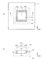
- FIG. 21A is a top view showing the configuration of the first solidified layer from the bottom as the bottom layer
- FIG. 21B is a cross-sectional view taken along the line II-II in FIG. is there.
- FIG. 22 shows the second layer obtained when the slice data of the first layer directly below and the slice data of the third layer directly above are superimposed on the slice data of the second layer as an example of the intermediate layer. It is a figure explaining the structure of slice data.
- FIG. 23 shows the third layer obtained when the slice data of the second layer immediately below and the slice data of the fourth layer immediately above are superimposed on the slice data of the third layer as another example of the intermediate layer. It is a figure explaining the structure of the slice data.
- FIG. 22 shows the second layer obtained when the slice data of the first layer directly below and the slice data of the third layer directly above are superimposed on the slice data of the second layer as an example of the intermediate layer. It is a figure explaining the structure of slice data.
- FIG. 23 shows the third layer obtained when the slice data of the second
- FIG. 24 shows the slice data of the (n ⁇ 1) th layer as an example of the intermediate layer when the protruding portion overlaps a part of the outer peripheral portion, It is a figure explaining the structure of the slice data of the (n-1) th layer when it overlaps with the slice data of the nth layer.
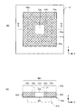
- FIG. 25 (a) is a top view showing the configuration of the second solidified layer as an example of the intermediate layer
- FIG. 25 (b) is a cross-sectional view taken along the line III-III in FIG. 25 (a).
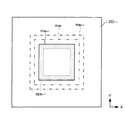
- FIG. 26A is a top view showing a configuration of a third solidified layer as another example of the intermediate layer
- FIG. 26B is a cross-sectional view taken along the line IV-IV in FIG. It is.
- FIG. 27A is a top view showing the configuration of the (n ⁇ 1) th solidified layer as an example of the intermediate layer in the case where the protruding portion overlaps a part of the outer peripheral portion
- FIG. FIG. 27A is a cross-sectional view taken along line VV in FIG. 27A
- FIG. 27C is a cross-sectional view taken along line VI-VI in FIG.
- FIG. 28A is a top view showing the configuration of the fourth solidified layer as the uppermost layer
- FIG. 28B is a cross-sectional view taken along line VII-VII in FIG.
- FIG. 29 is a view showing a cross-sectional structure in the height direction of the powder bed fusion bonded article according to the present embodiment.
- FIG. 30 shows the slice data of the (n ⁇ 1) th layer as an example of the intermediate layer when there is no protrusion in the modeling area, It is a figure explaining the structure of the slice data of the (n-1) th layer when it overlaps with slice data.
- FIG. 31 shows the slice data of the (n ⁇ 1) th layer as another example of the intermediate layer when there is no protrusion in the modeling area, the slice data of the immediately below (n ⁇ 2) th layer, and the nth layer of the immediately above It is a figure explaining the structure of the slice data of the (n-1) th layer when it overlaps with the slice data of.
- FIG. 32A is a top view showing an example of the configuration of the (n ⁇ 1) -th solidified layer as an example of the intermediate layer in the case where there is no protruding portion in the modeling region, and FIG. FIG. 32 is a sectional view taken along line VIII-VIII in FIG.
- FIG. 33A is a top view showing the configuration of the (n ⁇ 1) th solidified layer as another example of the intermediate layer in the case where there is no protrusion in the modeling region, and FIG. It is sectional drawing in the IX-IX line of (a).
- FIG. 34 is a diagram showing a cross-sectional structure in the height direction of a powder bed fusion bonded article according to a comparative example.
- the properties indicating the strength of a modeled object for example, there is toughness indicating tenacity. If this toughness is small, the modeled object tends to break.
- the inventor of the present application investigated the cause of reduced toughness when a molded object was produced with a powder bed fusion bonding apparatus using resin powder, and the cause was the pores formed in the molded object. I found.
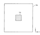
- FIG. 1 is a cross-sectional view showing an example of the structure of a shaped article produced with a powder bed fusion bonding apparatus using resin powder.
- pores may be formed in a molded article made of a powder bed fusion bonding apparatus using resin powder.
- Such pores include open pores OP in the open space formed on the surface (the upper surface 100 a, the lower surface 100 b, and the side surface 100 c) of the modeling object 100, and the closure formed inside the modeling object 100.
- the open pores OP are formed on the surfaces 100a to 100c of the molded article 100
- the stress when stress is applied to the molded article 100, the stress concentrates on the open pores OP, and the open pores OP are the starting points.
- the molded article 100 is easily broken.
- the toughness (strength) of the model is improved by suppressing the formation of open pores on the surface of the model as follows.
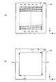
- FIG. 2 is a diagram for explaining an example of the configuration of the powder bed fusion bonding apparatus.
- FIG. 3A is a top view showing a configuration other than the casing of the powder bed fusion bonding apparatus, and
- FIG. 3B is a cross-sectional view taken along the line II in FIG.
- the powder bed fusion bonding apparatus 1 includes, in its housing 2, two storage containers 3 and 4 that store powder materials, and a molded article using the powder materials of the storage containers 3 and 4. And the production container 5 from which the product is produced is accommodated.
- the kind of the powder material is not particularly limited.
- a powder material polyphenylene sulfide (PPS), polybutylene terephthalate (PBT), nylon 6, nylon 11, and nylon 12 (nylon is a registered trademark), polyamide (PA), polypropylene (PP), and elastomer (EL And other thermoplastic resin powders.
- the storage containers 3 and 4 are formed by, for example, bending and welding a steel plate and opening in a rectangular shape when viewed from above. This is a cylindrical container.
- supply tables 6 and 7 Supplied inside the storage containers 3 and 4 are supply tables 6 and 7, respectively.
- the powder material 8 is supplied from the outside onto the supply tables 6 and 7.
- support rods 9 and 10 connected to a driver (not shown) are attached to the lower surfaces of the supply tables 6 and 7. By driving the support rods 9 and 10 with these drivers, the supply tables 6 and 7 are moved up and down inside the storage containers 3 and 4 via the support rods 9 and 10.
- the production container 5 is a cylindrical container that is formed, for example, by bending and welding a steel plate and opening in a square shape when viewed from above.
- a shaping table 11 is arranged inside the production container 5.
- the powder material 8 of the storage containers 3 and 4 is supplied onto the modeling table 11.
- a support bar 12 connected to a driver (not shown) is attached to the lower surface of the modeling table 11. By driving the support bars 9 and 10 with this driver, the modeling table 11 moves up and down the inside of the production container 5 through the support bar 12.
- a transport plate 13 is installed on the storage containers 3, 4 and the production container 5.
- a recoater 14 is provided on the transport plate 13.
- the transport plate 13 is a steel plate having a flat upper surface 13a and a lower surface 13b, and is provided with three through holes 13c to 13e.
- the left through hole 13c and the right through hole 13e have the same shape and size as the upper openings of the storage containers 3 and 4.
- the central through hole 13d has the same shape and size as the upper opening of the production container 5.
- the storage container 3 when the storage container 3 is disposed under the through-hole 13c, the preparation container 5 is disposed under the through-hole 13d, and the storage container 4 is disposed under the through-hole 13e, the through-hole 13c
- the holes 13d and the through holes 13e communicate with the upper opening of the storage container 3, the upper opening of the production container 5, and the upper opening of the storage container 4, respectively.
- the recoater 14 is an elongated metal plate standing in a direction perpendicular to the upper surface 13a of the transport plate 13, and is connected to a driver (not shown). By driving the recoater 14 by this driver, the recoater 14 moves leftward or rightward on the upper surface 13a of the transport plate 13.
- the feeding tables 6 and 7 and the modeling table 11 are moved up and down, and the recoater 14 is moved left and right, whereby the powder material 8 of the storage container 3 or the storage container 4 is transferred to the transport plate 13. It is transported to the production container 5 through the upper surface 13a and the through holes 13c to 13e. In this way, the powder material 8 in the storage containers 3 and 4 is supplied to the production container 5.
- the supply parts (resin material supply part) of the powder material 8 are constituted by the storage containers 3 and 4, the supply tables 6 and 7, the transport plate 13, and the recoater 14.
- upper heating units 15 to 17 and reflecting plates 18 and 19 are provided in the space in the housing 2 above the transport plate 13.
- the upper heating unit 15 is disposed above the storage container 3 and includes two rod-shaped heaters 20 and 21.
- the upper heating unit 16 is disposed above the storage container 4 and includes two rod-shaped heaters 22 and 23.
- These heaters 20 to 23 are infrared heaters or resistance heaters, and are arranged in parallel to each of these side portions inside the longitudinal side portions of the storage containers 3 and 4 when viewed from above. Yes.
- the powder material 8 in the storage containers 3 and 4 is heated from above by the heaters 20 to 23.
- the upper heating unit 17 is disposed above the production container 5 and includes four rod-shaped heaters 24 to 27.
- These heaters 24 to 27 are infrared heaters or resistance heaters, and are installed in parallel to each of these side portions inside all the side portions of the production container 5 when viewed from above. Thereby, the powder material 8 of the production container 5 is heated from above.
- the reflection plates 18 and 19 are metal plates that are attached to a support column in the housing 2 (not shown) and are set up in a direction perpendicular to the upper surface 13 a of the transport plate 13. And between the production container 5 and the storage container 4.
- the left reflector 18 has a mirror-finished surface on the production container 5 side (right surface), and the right reflector 19 has a mirror-finished surface on the production container 5 side (left surface). ing.
- the reflectors 18 and 19 can heat the powder material 8 of the production container 5 by reflecting the heat (infrared rays) of the heaters 24 to 27. For this reason, while heating the powder material 8 of the production container 5 to a predetermined temperature, the upper heating part 17 can maintain the temperature with little power consumption.
- the reflectors 18 and 19 are connected to the upper portions 18a and 19a via the upper portions 18a and 19a fixed to the support column in the housing 2 and the hinges 18b and 19b, respectively, and can swing left and right. It consists of lower parts 18c and 19c. Due to the structure of the reflection plates 18 and 19, the recoater 14 can pass through the reflection plates 18 and 19 via the lower portions 18c and 19c.
- the powder bed melt bonding apparatus 1 is also provided with a heating unit other than the upper heating units 15 to 17.
- a side heating unit that heats the powder material 8 of the preparation container 5 from the side is provided on the side of the preparation container 5.
- a lower heating unit for heating the powder material 8 of the production container 5 from below is provided between the modeling table 11 and the support rod 12.
- the lower surface 13 b of the transport plate 13 is provided with a transport plate heating unit that heats the powder material 8 in contact with the transport plate 13.
- Each of these heating units includes a plate-shaped resistance heating heater with a temperature sensor.
- the storage containers 3 and 4, the production container 5, the transport plate 13, the recoater 14, the upper heating units 15 to 17, the reflection plates 18 and 19, and the like are arranged in the housing 2.
- two glass windows 2 a and 2 b are fitted into the upper portion of the housing 2.
- a temperature detector 28 is provided above one window 2a.
- the temperature detection unit 28 is a device that detects the temperature by infrared rays, and is disposed inside the side portion of the production container 5 when viewed from above. Thereby, the temperature detection unit 28 can detect the surface temperature of the powder material 8 in the through hole 13 d of the transport plate 13 communicating with the opening of the production container 5.
- a plurality of temperature detection units 28 may be prepared, and each of these temperature detection units 28 may be disposed at different positions inside the side portion of the production container 5 when viewed from above. Thereby, the surface temperature of the powder material 8 can be detected with higher accuracy.
- the powder bed fusion bonding apparatus 1 includes, in addition to the temperature detection unit 28, the powder material 8 in the through holes 13 c and 13 e of the transport plate 13 communicating with the openings of the storage containers 3 and 4.
- a temperature detector for detecting the surface temperature is also provided.
- a laser beam emitting portion 29 is provided above the other window 2b.
- the laser beam emitting unit 29 is a device that emits laser beam and scans it, and is disposed inside the side of the production container 5 when viewed from above.
- the configuration of the laser beam emitting portion 29 is as follows.
- FIG. 4 is a block diagram illustrating the configuration of the laser beam emitting unit 29.
- the laser beam emitting unit 29 includes a light source 30, a mirror 31, a lens 32, and a driver 33.
- the light source 30 is, for example, a CO 2 laser light source that emits laser light having a wavelength of 10.6 ⁇ m.
- the light source 30 is not limited to a CO 2 laser light source, and may be a fiber laser light source that emits laser light having a wavelength of 1.07 ⁇ m.
- the mirror 31 has a galvanometer mirror as the X mirror 31a and a galvanometer mirror as the Y mirror 31b, and changes the angle of the laser light emitted from the light source 30 by changing the angles of the X mirror 31a and the Y mirror 31b. .
- the lens 32 moves in accordance with the movement of the laser beam emitted from the light source 30, and changes the focal length of the laser beam.
- the driver 33 changes the angles of the X mirror 31a and the Y mirror 31b and moves the lens 32.
- the laser beam emitted from the light source 30 passes through the lens 22, the X mirror 31a, and the Y mirror 31b in this order.
- the laser light is scanned in the X direction and the Y direction, and is applied to a specific region on the surface of the powder material 8 in the through hole 13d. It comes to be irradiated.
- the lens 32 is moved by driving the driver 33, so that the laser beam is focused on the surface of the powder material 8.
- a control unit 34 is disposed outside the housing 2.
- the control unit 34 is composed of a computer having a CPU (Central Processing Unit) and a memory.
- the memory stores a program for performing various processes related to the production of the modeled object, and the control unit 34 controls various devices of the powder bed fusion bonding apparatus 1 based on the program.
- control unit 34 outputs a control signal to the drivers of the support rods 9, 10, 12 to raise and lower the supply tables 6, 7 of the storage containers 3, 4 and the modeling table 11 of the production container 5. Further, the control unit 34 outputs a control signal to the driver of the recoater 14 to move the recoater 14 left and right on the upper surface 13 a of the transport plate 13.
- control part 34 is the powder material 8 used by preparation of a molded article, and the powder material in the through-holes 13c, 13d, and 13e of the conveyance board 13 output from the temperature detection part 28 and other temperature detection parts. 8 is used to output control signals to the heaters 20 to 27 of the upper heating sections 15 to 17 to adjust the surface temperatures of the powder material 8 in the through holes 13c, 13d, and 13e, respectively.
- control unit 34 outputs a control signal to the heater based on the temperature data output from the heater temperature sensor for the other heating units, and the temperature of the powder material 8 in the production container 5, And the temperature of the powder material 8 on the conveyance board 13 is adjusted.
- control unit 34 outputs a control signal to the laser beam emitting unit 29 based on the type of the powder material 8 described above and the slice data (drawing pattern) of the three-dimensional structure to be manufactured.
- the region irradiated with the laser beam and the energy density of the laser beam are adjusted.
- the slice data is obtained by slicing a three-dimensional structure to be produced at a predetermined interval (for example, 0.1 mm) in the height direction (Z direction) and dividing it into a plurality of layers (X direction and X direction). Data including the position in the Y direction).
- FIGS. 5 to 8 are diagrams for explaining an example of the configuration of slice data of each layer in the case where the modeled object to be produced is divided into four layers. 5 to 8, the slice data of FIG. 5 is slice data of the first layer (lowermost layer) from the bottom of the modeled object, and that of FIG. 6 is slice data of the second layer (intermediate layer). 7 is slice data of the third layer (intermediate layer), and that of FIG. 8 is slice data of the fourth layer (uppermost layer).
- slice data SD 1 of the first layer includes a data modeling area ma 1 comprising a first layer shaped article.
- the positions of the points in the slice data SD 1 including the modeling area ma 1 are represented by coordinates in the X direction and the Y direction.
- the outer periphery of the slice data SD 1 corresponds to the outer periphery of the through hole 13d of the carrying plate 13 (or, the opening of the produced container 5).
- the remaining slice data SD 2 to SD 4 of the second layer to the fourth layer have the same configuration as the slice data SD 1 of the first layer.
- FIG. 9 is a diagram illustrating a zigzag scanning method as an example of a laser beam scanning method.
- sc 1 to sc 9 are arranged in a zigzag pattern. Specifically, odd-numbered scanning lines sc 1 , sc 3 , sc 5 , sc 7 , sc 9 extending in the X direction are arranged in parallel at intervals, and further in an acute angle direction with respect to the X direction.
- the even-numbered scanning lines sc 2 , sc 4 , sc 6 , and sc 8 that extend are arranged in parallel at intervals. Then, the end points of the scanning lines sc 1 to sc 9 are connected to each other.
- the scanning lines sc 10 to sc 13 are arranged on the outer peripheral line ol of the modeling area ma of the slice data SD. Then, the end points of the scanning lines sc 10 to sc 13 are connected to each other.
- the control unit 34 controls the laser beam emitting unit 29 based on the slice data SD 1 to SD 4 and the zigzag scanning method described above, and corresponds to the modeling regions ma 1 to ma 4 of the slice data SD 1 to SD 4.
- Laser light is emitted and scanned in a thin layer region (modeling region) of the powder material 8 in the through hole 13d of the transport plate 13. In this way, the laser beam is irradiated onto the modeling region of the thin layer of the powder material 8.
- the laser beam scanning method is not limited to the zigzag scanning method.
- a scanning method of laser light a raster scanning method in which scanning lines sc extending in the same direction (for example, the X direction and the Y direction) are arranged in parallel with an interval with respect to the modeling region ma of the slice data SD
- a scanning method may be used in which the scanning lines sc are spirally arranged at intervals along the outer peripheral line ol.
- the energy density of laser light will be described.
- the energy density is represented by the following formula (1).
- E P / (V ⁇ SS ⁇ e) (1)
- E the energy density (J / m 3 ) of the laser beam
- P the output (W) of the laser beam
- V the scanning speed (m / s) of the laser beam
- SS the scanning interval (m) of the laser beam
- e the thickness (m) of the thin layer of the powder material 8.
- equation (1) for example, when the thickness e of the thin layer of the powder material 8 is the same, the output P is increased, the scanning speed V is decreased, or the scanning interval SS is decreased. Thereby, when irradiating a modeling area
- the laser light output P, the scanning speed V, and the scanning interval SS other than the thickness e of the thin layer of the powder material 8 can be changed by controlling the laser light emitting unit 29. It is.
- the control unit 34 controls the laser beam emitting unit 29 to change any one of the laser beam output P, the scanning speed V, and the scanning interval SS, so that the laser beam received by the thin layer forming region of the powder material 8 is received.
- the energy density E is adjusted.
- the powder bed fusion bonding apparatus 1 is configured as described above.
- the powder container is bonded after the production container 5 and the storage containers 3 and 4 supplied with the powder material 8 are accommodated in the casing 2 of the powder bed melt bonding apparatus 1. Assume that the device 1 is in the state shown in FIG.
- the upper surface of the powder material 8 of the storage containers 3 and 4 is the same height as the upper surface 13 a of the transport plate 13. Further, the upper surface of the modeling table 11 of the production container 5 is the same height as the upper surface 13 a of the transport plate 13.
- the recoater 14 is disposed on the left side of the storage container 3 in the upper surface 13 a of the transport plate 13.
- the control unit 34 forms a model based on the three-dimensional data of the model input from the outside of the apparatus 1 and the type of the powder material 8. Is created and stored in the memory.
- control unit 34 controls the driver of the support bar 9 of the storage container 3, the driver of the support bar 10 of the storage container 4, the driver of the support bar 12 of the preparation container 5, and the driver of the recoater 14, and thereby the preparation container A buffer layer of the powder material 8 is formed on the 5 modeling table 11.
- the modeling object 11 is placed on the modeling table 11. A buffer layer of the powder material 8 is formed.
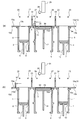
- 10 to 13 are cross-sectional views during the formation of the buffer layer.
- control unit 34 controls the driver of the support rod 9 of the left storage container 3 to raise the supply table 6. Thereby, the powder material 8 of the storage container 3 is protruded above the upper surface 13a of the conveyance board 13 through the through-hole 13c.
- control unit 34 controls the driver of the support rod 12 of the production container 5 to lower the modeling table 11 by a thickness of a thin layer of the powder material 8, for example, 0.1 mm, and on the right side.
- the driver of the support rod 10 of the storage container 4 is controlled to lower the supply table 7.
- the control unit 34 controls the driver of the recoater 14 to move the recoater 14 to the right on the upper surface 13 a of the transport plate 13.
- the recoater 14 scrapes the powder material 8 of the storage container 3 protruding from the upper surface 13a and transports it to the preparation container 5 through the upper surface 13a and the through hole 13d.
- the powder material 8 of the storage container 3 is supplied to the production container 5, and the thin layer 35 of the first layer of powder material 8 is formed on the modeling table 11.
- control unit 34 moves the recoater 14 to the right.
- the recoater 14 is made to carry the powder material 8 which was not used for formation of the thin layer 35 to the storage container 4 via the upper surface 13a and the through-hole 13e.
- control unit 34 stops the recoater 14 at a position on the right side of the storage container 4.
- control unit 34 raises the supply table 7 of the storage container 4. Thereby, the powder material 8 of the storage container 4 is protruded above the upper surface 13a of the conveyance board 13 through the through-hole 13e.
- control unit 34 lowers the modeling table 11 of the production container 5 by the thickness of one layer of the thin layer of the powder material 8 described above and lowers the supply table 6 of the storage container 3.
- the control unit 34 moves the recoater 14 leftward on the upper surface 13 a of the transport plate 13.
- the recoater 14 scrapes the powder material 8 of the storage container 4 protruding from the upper surface 13a and transports it to the preparation container 5 through the upper surface 13a and the through hole 13d.
- the powder material 8 of the storage container 4 is supplied to the production container 5, and the thin layer 36 of the second layer of the powder material 8 is formed on the modeling table 11.
- control unit 34 moves the recoater 14 in the left direction.
- the recoater 14 conveys the powder material 8 which is not used for forming the thin layer 36 to the storage container 3 through the upper surface 13a and the through hole 13c.
- control unit 34 stops the recoater 14 on the left side of the storage container 3.
- the thin layer 37 of the third powder material 8 is formed on the second thin layer 36 in the same manner as the formation of the first thin layer 35. Further, a thin layer 38 of the fourth powder material 8 is formed on the third thin layer 37 in the same manner as the formation of the second thin layer 36.
- the thin layers 36 to 38 of the powder material 8 are laminated on the modeling table 11 of the production container 5, A buffer layer 39 having a thickness of 10 mm (for example, 10 mm) is formed.
- the thin layers 36 to 38 of the four layers of the powder material 8 are shown as the buffer layer 39, but the actual number of thin layers of the powder material 8 depends on the thickness of the buffer layer 39. Number of layers.
- control unit 34 controls the heaters 20 to 27 of the upper heating units 15 to 17 to preheat the powder material 8 in the storage containers 3 and 4 and the powder material 8 in the production container 5.
- the powder material 8 is melt bonded and solidified to form a solidified layer by irradiating the modeling region of the thin layer of the powder material 8 with laser light as will be described later. At this time, if the temperature difference between the modeling region irradiated with the laser beam in the thin layer of the powder material 8 and the surrounding region is large, the solidified layer is excessively contracted after being irradiated with the laser beam, and solidified. Warping may occur in the layer.
- the powder material 8 in the storage containers 3 and 4 and the powder material 8 in the preparation container 5 are preheated before the production of the shaped object is started.
- the preheating method will be described.
- control unit 34 controls the heaters 20 to 27 of the upper heating units 15 to 17 and other heating units (side heating unit, lower heating unit, and transport plate heating unit). Turn on the heater.
- control part 34 is the data of the kind of powder material 8, and the surface temperature of the powder material 8 in the through-holes 13c, 13d, and 13e of the conveyance board 13 output from the temperature detection part 28 and other temperature detection parts. Based on the above, the heat generation amount of the heaters 20 to 27 is adjusted. Furthermore, the control part 34 adjusts the emitted-heat amount of a heater based on the data of the temperature output from the temperature sensor of a heater about another heating part.
- the surface of the powder material 8 in the through hole 13c, the through hole 13d, and the through hole 13e of the transport plate 13 is raised to a predetermined temperature and maintained at that temperature.
- the surface of the powder material 8 in the through-hole 13d communicating with the opening of the production container 5 is at a temperature suitable for starting production of a shaped object, for example, about 10 ° C. to 15 ° C. above the melting point of the powder material 8 Maintained at low temperature.
- the surface of the powder material 8 in the through hole 13d is maintained at a temperature of about 115 ° C. to 120 ° C. as an appropriate temperature. Is done.
- the powder material 8 is preheated.
- Such preheating is continuously performed not only during the formation of the buffer layer 39 but also during the formation of a shaped article on the buffer layer 39 described later.
- all the heaters of the powder bed melt bonding apparatus 1 are turned on simultaneously with the start of the formation of the buffer layer 39, but before the start of formation of the buffer layer 39, the powder bed melt bonding apparatus 1 is turned on. All of the heaters may be turned on. For example, all the heaters of the powder bed fusion bonding apparatus 1 may be turned on immediately after the storage containers 3 and 4 and the production container 5 are accommodated in the housing 2 of the powder bed fusion bonding apparatus 1.
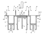
- 14 to 18 are cross-sectional views in the middle of production of a modeled object.
- the controller 34 raises the supply table 6 of the left storage container 3 as shown in FIG. Thereby, the powder material 8 of the storage container 3 is protruded above the upper surface 13a of the conveyance board 13 through the through-hole 13c.
- control unit 34 lowers the modeling table 11 by the thickness (0.1 mm) of the thin layer of the powder material 8 described above and lowers the supply table 7 of the right storage container 4.
- the control unit 34 moves the recoater 14 rightward on the upper surface 13 a of the transport plate 13.
- the recoater 14 scrapes the powder material 8 of the storage container 3 protruding from the upper surface 13a and transports it to the preparation container 5 through the upper surface 13a and the through hole 13d.
- the thin layer 40 of the powder material 8 of the first layer is formed on the buffer layer 39 for forming a molded article.
- the recoater 14 by moving the recoater 14 to the right, the recoater 14 has the upper surface 13a and the through-holes 13e with the powder material 8 remaining without being used to form the thin layer 40.
- the storage container 4 Through the storage container 4.
- control unit 34 stops the recoater 14 on the right side of the storage container 4.
- control unit 34 controls the laser beam emitting unit 29 based on the slice data SD 1 of the first layer, into shaped region ma 1 slice data SD 1 Laser light is emitted and scanned in the corresponding region (modeling region) of the thin layer 40 of the first layer.
- the modeling region of the first thin layer 40 is irradiated with laser light.
- the powder material 8 in this modeling area is melt-bonded and solidified to form the first solidified layer 40a.
- control unit 34 stops the emission and scanning of the laser light.
- control unit 34 raises the supply table 7 of the right storage container 4. Thereby, the powder material 8 of the storage container 4 is protruded above the upper surface 13a of the conveyance board 13 through the through-hole 13e.
- control unit 34 lowers the modeling table 11 by the thickness of one layer of the thin layer of the powder material 8 and lowers the supply table 6 of the left storage container 3.
- the control unit 34 moves the recoater 14 leftward on the upper surface 13 a of the transport plate 13.
- the recoater 14 scrapes the powder material 8 of the storage container 4 protruding from the upper surface 13a and transports it to the preparation container 5 through the upper surface 13a and the through hole 13d.
- the thin layer 41 of the second layer powder material 8 is formed on the first thin layer 40 on which the solidified layer 40a is formed.
- control unit 34 moves the recoater 14 leftward so that the powder material 8 remaining without being used for forming the thin layer 41 is transferred to the recoater 14 on the upper surface 13a. And it is made to convey to the storage container 3 through the through-hole 13c.
- control unit 34 stops the recoater 14 on the left side of the storage container 3.
- control unit 34 controls the laser beam emitting unit 29 based on the slice data SD 2 of the second layer, the shaped region ma 2 of slice data SD 2 Laser light is emitted and scanned in the region (modeling region) of the corresponding thin layer 41 of the second layer.
- the laser beam is irradiated to the modeling region of the second thin layer 41.
- the powder material 8 in this modeling region is melt-bonded and solidified to form the second solidified layer 41a.
- control unit 34 stops the emission and scanning of the laser light.
- the third layer powder material 8 is formed on the second thin layer 41 and the solidified layer 41a.
- the fourth thin layer 42 and the solidified layer 42a are formed on the third thin layer 42 and the solidified layer 42a.
- a thin layer 43 and a solidified layer 43a of the powder material 8 of the layer are formed.
- the solidified layers 40a to 43a are formed on the buffer layer 39 in the production container 5 as shown in FIG. Are stacked to produce a three-dimensional structure 44.
- control unit 34 adjusts the energy density E of the laser beam applied to the modeled areas of the thin layers 40 to 43 as follows.
- 19 and 20 show the energy density E of the laser light applied to the modeling region of the thin layer of the powder material 8 of n (n is an integer of 3 or more), which is performed in the control unit 34 when the modeled object is manufactured. It is a flowchart explaining the adjustment method.
- step S ⁇ b> 11 the control unit 34 creates slice data SD of a modeled object to be manufactured based on the three-dimensional data of the modeled object and the type of the powder material 8 as described above. Store in memory.
- the control unit 34 shows the slice data of the shaped article as shown in FIG. 5 to FIG. Slice data SD 1 to SD 4 are created and stored in the memory.
- control unit 34 controls the support rods 9, 10, 12 and the recoater 14 to form the buffer layer 39 as shown in FIGS. 10 to 13, and the heaters 20 to 27 to control the powder material. 8 is preheated.
- control proceeds to step S12, the control unit 34 reads out the slice data SD 1 from the bottom of the molded object from the memory the first layer.
- control unit 34 controls the support rods 9, 10, 12 and the recoater 14 to form the first thin layer 40 of the powder material 8 as shown in FIGS. 14 (a) to 15 (a). Form.
- control unit 34 controls the laser beam emitting unit 29 based on the slice data SD 1 of the first layer corresponds to the shaping region ma 1 of the slice data SD 1
- the entire modeling area of the first thin layer 40 is irradiated with laser light at an energy density E 1 higher than the normal energy density E 2 .
- the ordinary energy density E 2 is set according to the type of powder material 8, is that the energy density E of the powder material 8 that is preheated to minimum melt bonding. Energy density E 1 is higher than its normal energy density E 2.
- control unit 34 controls the laser beam emitting unit 29 to output the light source 30 to the entire modeling region of the first thin layer 40 with the normal energy density E 2.
- the laser beam is emitted with an output P 1 larger than 2, and the scanning velocity V 1 and the scanning line interval SS are the same as the scanning velocity V 2 and the scanning line interval SS 2 when the driver 33 is irradiated with the normal energy density E 2. 1 , the laser beam is zigzag scanned as shown in FIGS. 9 (a) and 9 (b).
- the energy density E of the laser beam received by the entire modeling region of the first thin layer 40 is set to an energy density E 1 higher than the normal energy density E 2 .
- step S13 the first solidified layer 40a is formed in the modeling region of the thin layer 40 of the first powder material 8 as shown in FIG.
- FIG. 21A is a top view showing the configuration of the first solidified layer 40a from the bottom as the bottom layer
- FIG. 21B is a cross-sectional view taken along the line II-II in FIG. It is.
- a solidified layer 40a is formed in the modeling region MA1 of the first thin layer 40.
- FIG. 21 (a) the whole of the building area MA 1 shown in mesh is (b), the laser beam is irradiated with a high energy density E 1 than conventional energy density E 2. Therefore, it is possible to firmly fusion bonded powder material 8 of the shaped area MA 1.
- the surface (upper surface 40b, lower surface 40c and side surface 40d) of the solidified layer 40a open pores formed on the entire (see open pores OP of FIG. 1), laser light is irradiated in a normal energy density E 2 The number of open pores formed in this case can be reduced.
- closed porosity CP in Figure 1 closed pores are formed in the solidified layer 40a also the laser light is less than the closed pores formed when irradiated with conventional energy density E 2 Can do.
- the porosity of the pores (open pores and closed pores) formed in the solidified layer 40a can be reduced to a range of 0.1% to 5%, preferably 0.1% to 1%. it can.
- the energy density E 1 is excessively higher than the normal energy density E 2 , bubbles are generated in the molten powder material 8, and the open pores and closed pores formed in the solidified layer 40 a may be reduced. It may not be possible.
- the energy density E 1 is set to a magnitude of about 1.2 to 2 times the energy density E 2 .
- control unit 34 reads out slice data SD n ⁇ 1 of the (n ⁇ 1) th layer of the modeled object from the memory.
- control unit 34 recognizes that the (n ⁇ 1) th layer of the modeled object is one of the intermediate layers, and controls the support bars 9, 10, 12 and the recoater 14, for example, FIG. 16 (a) to FIG.
- a thin layer 41 of the second layer powder material 8 is formed as an intermediate layer as shown in FIG. 17A, or a thin layer 42 of the third layer powder material 8 is formed as shown in FIG. To do.
- step S15 the control unit 34 extracts the outer peripheral part opa n-1 of the modeling area mann -1 of the slice data SD n-1 of the ( n-1) th layer.
- step S15 the control unit 34, as the outer peripheral portion opa n-1, the shaped region ma n-1 from the peripheral line inside a predetermined width, for example, the thickness of the width of the thin layer of powder material 8 (0 .1 mm) is extracted.
- step S16 the control unit 34 refers to the slice data of the (n-2) th layer and the slice data of the nth layer of the modeled object in the memory, and refers to the slice data of the (n-1) th layer. detecting the protruding portion pa n-1 slice data SD n-1 of the shaped region ma n-1.
- step S16 first, the control unit 34 superimposes the slice data SD n ⁇ 1 of the ( n ⁇ 1) th layer on the slice data of the (n ⁇ 2) th layer immediately below the slice data SD n ⁇ 1 . of slice data SD n-1 of the shaped region ma n-1, to detect the portion that protrudes outward from the shaping region ma n-2 of the n-2 layer of the slice data when viewed from below.
- control unit 34 the slice data SD n-1 of the (n-1) th layer, overlapping the n-th layer of the slice data directly thereon, of the n-1 th layer slice data SD n-1 of shaped region ma n-1 of detecting a portion that extends outside from the shaped region ma n of the n-th layer of the slice data when viewed from above.
- control unit 34 as the protruding portion pa n-1 of the shaped region ma n-1 of the (n-1) th layer, a moiety that extends outside from the shaped region ma n-2 when viewed from below and detecting a portion is a portion that protrudes outward from the shaping region ma n when viewed from above.
- Figure 22 is the slice data SD 2 of the second layer as an example of an intermediate layer, when superimposed on the slice data SD 1 of the first layer directly below, and the slice data SD 3 of the third layer immediately above it is a diagram illustrating a second layer of slice data SD 2 of the configuration of.
- the modeling area ma 2 of the slice data SD 2 of the second layer is indicated by a solid line.
- the modeling area ma 1 of the first layer slice data SD 1 is indicated by a one-dot chain line
- the modeling area ma 3 of the third layer slice data SD 3 is indicated by a two-dot chain line.
- step S15 the control unit 34, as the outer peripheral portion opa 2 of the shaped region ma 2 of the second layer, the shaped portion having a predetermined width from the peripheral line on the inside of the region ma 2 (Fig. 22, portions of the satin ).
- the modeling area ma 2 of the second layer is smaller than the modeling area ma 3 of the third layer directly above, and conversely, than the modeling area ma 1 of the first layer immediately below. large. Therefore, the second layer of the modeling area ma 2 has no portion protruding outward from the third layer of the modeling area ma 3 when viewed from above, but the first layer when viewed from below. There is a portion that protrudes outward from the modeling area ma 1 of the eye.
- step S ⁇ b> 16 the control unit 34 sets only the portion that protrudes outward from the modeling region ma 1 when viewed from below as the protruding portion pa 2 of the modeling region ma 2 of the second layer ( In FIG. 22, a hatched portion that rises to the right is detected.
- FIG. 23 the slice data SD 3 of the third layer of another example of an intermediate layer, a slice data SD 2 of the second layer directly below, the fourth layer immediately above the slice data SD 4 it is a diagram illustrating a third layer of a structure of slice data SD 3 when stacked.
- the modeling area ma 3 of the slice data SD 3 of the third layer is indicated by a solid line.
- the modeling area ma 2 of the slice data SD 2 of the second layer is indicated by a one-dot chain line
- the modeling area ma 4 of the slice data SD 4 of the fourth layer is indicated by a two-dot chain line.
- step S15 the control unit 34, as the outer peripheral portion opa 3 of the third layer modeling area ma 3, has a portion with a predetermined width on the inner side from the outer peripheral line of the modeling area ma 3 (in FIG. 23, a satin portion ).
- the modeling area ma 3 of the third layer is larger than the modeling area ma 4 of the fourth layer immediately above, and further larger than the modeling area ma 2 of the second layer immediately below. .
- the third layer of the modeling area ma 3 has a portion protruding outward from the fourth layer of the modeling area ma 4 when viewed from above, and the second layer of the modeling area ma 3 when viewed from below. There is a portion protruding from the modeling region ma 2 to the outside.
- control unit 34 is a portion that protrudes outward from the modeling region ma 4 when viewed from above as the protruding portion pa 3 of the modeling region ma 3 of the third layer. and (in FIG. 23, the right hatched portion of the raised) portion is a portion that protrudes outward from the shaping region ma 2 when viewed from below to detect.
- control proceeds to step S17, the control unit 34 determines whether there is a portion pa n-1 protrudes into shaped region ma n-1 of the (n-1) th layer of the slice data SD n-1 .
- step S17 in case it is determined that there is no protruding portion pa n-1 into shaped region ma n-1 of the (n-1) th layer of the slice data SD n-1 (the case of NO), step S25 (FIG. 20 To see).
- step S17 in case it is determined that the (n-1) th layer of the slice data SD n-1 of the shaped region ma n-1 to the protruding portion pa n-1 is (in case of YES), the step S18 Transition.
- the protruding part may overlap only a part of the outer peripheral part of the intermediate layer.
- FIG. 24 shows the slice data SD n ⁇ 1 of the n ⁇ 1th layer as an example of the intermediate layer when the protruding portion overlaps a part of the outer peripheral portion, and the slice data of the immediately below n ⁇ 2th layer
- FIG. 6 is a diagram for explaining the configuration of slice data SD n ⁇ 1 of the ( n ⁇ 1) th layer when the slice data of the nth layer directly above is overlapped.
- FIG 24 it illustrates the first n-1 th layer of the slice data SD n-1 a shaped region ma n-1 by the solid line.
- the shaped region ma n-2 of the n-2 layer of the slice data indicated by a chain line indicates a shaped region ma n of the n-th layer of the slice data by a two-dot chain line.
- the protruding portion pan -1 is present at the entire end portions in the Y direction of the modeling region mann -1 , but is not present at the entire end portions in the X direction.
- the protruding portion pan -1 overlaps only a part of the outer peripheral portion opan -1 of the intermediate layer.
- step S16 the control unit 34, as the protruding portion pa n-1 of the (n-1) th layer of the shaped region ma n-1, from the shaped region ma n-1 when viewed from below A portion that protrudes outward (in FIG. 24, a portion with a diagonal line rising to the right) is detected.
- step S17 it is determined that the modeling region mann -1 has the protruding portion pann -1 , and the process proceeds to step S18.
- step S18 the control unit 34 refers to the slice data of the (n-2) th layer and the slice data of the nth layer in the memory, and forms the slice data SDn -1 of the ( n-1) th layer. detecting the overlapping portion oa n-1 region ma n-1.
- the control unit 34 as the overlap portions oa n-1, of the shaped region ma n-1 of the (n-1) th layer of the slice data SD n-1, the n-2 layer vertically adjacent overlapping the shaped region ma n-2 and the shaping region ma n of the n-th layer of the slice data of the eye of the slice data, the protruding portion pa n-1 of the inner predetermined width, for example, the thickness of the thin layer of powder material 8 A portion having a width (0.1 mm) is detected.
- the width of the overlapping portion oa n-1 is not limited to the width corresponding to the thickness of the thin layer of the powder material 8.
- the width of the overlapping portion oa n-1 may be larger than the thickness of the thin layer of the powder material 8 according to the type (hardness) of the powder material 8.
- step S ⁇ b > 18 the control unit 34 uses the first layer modeling region ma 1 and the third layer modeling region ma 3 as the overlapping portion oa 2 of the second layer modeling region ma 2.
- a portion having a predetermined width inside the protruding portion pa 2 that overlaps with (in FIG. 22, a hatched portion with a downward slope to the right) is detected.
- control unit 34 overlaps the second layer modeling region ma 2 and the fourth layer modeling region ma 4 as the overlapping portion oa 3 of the third layer modeling region ma 3.
- a portion with a predetermined width inside the protruding portion pa 3 (in FIG. 23, a portion with a slanting line to the right) is detected.
- control unit 34 as the overlap portions oa n-1 of the shaped region ma n-1 of the (n-1) th layer, the shaped region of the n-2 th layer ma n-2 and portion of the predetermined width of the protrusion portion inside of the pa n-1 overlaps with the shaped region ma n of the n-th layer (in FIG. 24, the right hatched portion of edge) is detected.
- step S19 the control unit 34 controls the laser beam emitting unit 29 based on the slice data SD n ⁇ 1 of the (n ⁇ 1) th layer as the intermediate layer, and this slice data SD n -1 of the modeling region of the (n ⁇ 1) th thin layer corresponding to the modeling region ma n ⁇ 1 , the portion corresponding to the protruding portion pan n ⁇ 1 and the overlapping portion oa n ⁇ 1 (the protruding portion and the overlapping portion) ) Is irradiated with a laser beam at an energy density E 1 higher than the normal energy density E 2 , and a portion corresponding to the inner portion of the protruding portion pan n-1 and the overlap oa n-1 (center portion) relative to a laser beam at a normal energy density E 2.
- control unit 34 controls the laser beam emitting unit 29 so that the normal energy density E 2 is supplied to the light source 30 with respect to the protruding portion and the overlapping portion in the modeling region of the (n ⁇ 1) th thin layer.
- the laser beam is emitted with an output P 1 that is larger than the output P 1 when irradiated with the laser beam (normal output) P 2 , and the scanning speed (normal scanning speed) V when the driver 33 is irradiated with the normal energy density E 2.
- 2 and the scanning line interval (normal scanning line interval) SS 2 are zigzag scanned with the laser beam at the same scanning speed V 1 and scanning line interval SS 1 .
- control unit 34 the central portion of the shaping region of the n-1 layer of the thin layer, the light source 30 in the normal output P 2 together emit laser light, a normal driver 33
- the laser beam is zigzag scanned at the scanning speed V 2 and the scanning line interval SS 2 .
- the order of laser beam emission and scanning is not limited to this.
- the laser beam may be emitted and scanned to the protruding portion and the overlapping portion.
- the energy density E of the laser beam received by the protruding portion and the overlapping portion in the modeling area of the (n ⁇ 1) th thin layer as the intermediate layer is higher than the normal energy density E 2. while the E 1, the energy density E of the laser beam central portion is subjected to the usual energy density E 2.
- a second solidified layer 41a is formed in the modeling region of the thin layer 41 of the second powder material 8, or as shown in FIG.
- a solidified layer 42 a of the third layer is formed in the modeling region of the thin layer 42 of the powder material 8 of the third layer.
- FIG. 25A is a top view showing a configuration of the second solidified layer 41a as an example of the intermediate layer
- FIG. 25B is a cross-sectional view taken along the line III-III in FIG. It is.
- the second solidified layer 41a is indicated by a solid line.
- the first solidified layer 40a formed immediately below the solidified layer 41a is indicated by a one-dot chain line
- the third solidified layer 42a formed immediately above the solidified layer 41a is indicated by a two-dot chain line.
- a solidified layer 41a is formed in the modeling region MA2 of the second thin layer 41.
- the central portion CA 2 shown as plain in FIGS. 25A and 25B is irradiated with laser light at a normal energy density E 2 .
- the protruding portion PA 2 and the overlapping portion OA 2 shown by the meshes in FIGS. 25A and 25B are irradiated with laser light at an energy density E 1 higher than the normal energy density E 2 .
- the powder material 8 of the protruding portion PA 2 and the overlapping portion OA 2 can be firmly melt-bonded.
- the surface (upper surface 41b, lower surface 41c and side surface 41d) of the solidified layer 41a of the protruding portion open pores formed in a portion of the PA 2 and overlapping portion OA 2 of the laser light is in the usual energy density E 2 It can be less than the open pores formed when irradiated.
- the closed pores formed in the protruding portion PA 2 and the overlapping portion OA 2 in the solidified layer 41a are also more closed than the closed pores formed when the laser beam is irradiated with the normal energy density E 2. Can also be reduced.
- the porosity of the pores (open pores and closed pores) formed in the protruding portion PA 2 and the overlapping portion OA 2 of the solidified layer 41a is in the range of 0.1% to 5%, preferably 0.1%. It can be reduced to a range of ⁇ 1%.
- FIG. 26 (a) is a top view showing a configuration of a third solidified layer 42a as another example of the intermediate layer, and FIG. 26 (b) is a IV-IV line in FIG. 26 (a).
- FIG. 26 (b) is a top view showing a configuration of a third solidified layer 42a as another example of the intermediate layer, and FIG. 26 (b) is a IV-IV line in FIG. 26 (a).
- the third solidified layer 42a is indicated by a solid line.
- the second solidified layer 41a formed immediately below the solidified layer 42a is indicated by a one-dot chain line
- the fourth solidified layer 43a formed immediately thereon is indicated by a two-dot chain line.
- a solidified layer 42a is formed in the modeling region MA3 of the third thin layer 42.
- FIG. 26 (a) the in central CA 3 shown with a solid in (b), the laser light is applied in the usual energy density E 2.
- the protruding portion PA 3 and the overlapping portion OA 3 shown by the meshes in FIGS. 26A and 26B are irradiated with laser light at an energy density E 1 higher than the normal energy density E 2 .
- the powder material 8 of the protruding portion PA 3 and the overlapping portion OA 3 can be firmly melt-bonded.
- the surface (upper surface 42b, lower surface 42c and 42d side) of the solidified layer 42a of the protruding portion open pores formed in a portion of PA 3 and overlapped portion OA 3 of, the laser beam at normal energy density E2 irradiation This can be less than the open pores that are formed.
- the closed pores formed in the protruding portion PA 3 and the overlapping portion OA 3 in the solidified layer 42a are also more closed than the closed pores formed when the laser beam is irradiated with the normal energy density E 2. Can also be reduced.
- the porosity of the pores (open pores and closed pores) formed in the protruding portion PA 3 and the overlapping portion OA 3 of the solidified layer 42a is in the range of 0.1% to 5%, preferably 0.1%. It can be reduced to a range of ⁇ 1%.
- FIG. 27A is a top view showing the configuration of the (n ⁇ 1) th solidified layer as an example of the intermediate layer when the protruding portion overlaps a part of the outer peripheral portion.
- 27B is a cross-sectional view taken along line VV in FIG. 27A
- FIG. 27C is a cross-sectional view taken along line VI-VI in FIG.
- a solidified layer 45a is formed in the modeling region MA n-1 of the thin layer 45 of the ( n-1) th layer.
- the solidified layer 45a of the (n-1) th layer is shown by a solid line.
- the (n-2) th solidified layer 46a formed immediately below the solidified layer 45a is indicated by a one-dot chain line
- the n-th solidified layer 47a formed immediately above it is indicated by a two-dot chain line. ing.
- the central portion CA n ⁇ 1 shown as plain in FIGS. 27A to 27C is irradiated with laser light with a normal energy density E 2 .
- the open pores formed in the outer peripheral portion OPA n-1 , the protruding portion PA n-1 and the overlapping portion OA n-1 of the surface (upper surface 45b, lower surface 45c and side surface 45d) of the solidified layer 45a are formed.
- the number of open pores formed when the laser beam is irradiated with the normal energy density E 2 can be reduced.
- the laser beam is in a normal energy density E 2
- E 2 The number of closed pores formed when irradiated can be reduced.
- the porosity of the pores (open pores and closed pores) formed in the outer peripheral portion OPA n-1 and the protruding portion PA n-1 and the overlapping portion OA n-1 of the solidified layer 45a is 0.1% to It can be reduced to a range of 5%, preferably 0.1% to 1%.
- step S20 the control unit 34 reads the slice data of the nth layer of the modeled object from the memory.
- step S21 the control unit 34 refers to the slice data SD in the memory and determines whether or not the nth layer of the shaped object is the uppermost layer.
- the control unit 34 when the control unit 34 reads out the slice data of the nth layer of the modeled object and the memory has no slice data of the (n + 1) th layer, the nth layer of the modeled object is the top layer. judge. On the other hand, when there is the (n + 1) th layer slice data in the memory, the control unit 34 determines that the nth layer of the modeled object is not the uppermost layer.
- Step S21 when it is determined that the nth layer of the modeled object is not the uppermost layer (in the case of NO), the process returns to Step S15.
- control unit 34 recognizes that the n-th layer of the modeled object is one of the intermediate layers, and performs the processing from step S15 to step S19 on the modeling region of the thin layer of the n-th layer. Then, it transfers to step S20 and the control part 34 reads the slice data of the (n + 1) th layer of a modeling thing from memory.
- step S21 if it is determined in step S21 that the nth layer of the shaped object is the uppermost layer (in the case of YES), the process proceeds to step S22.
- control unit 34 controls the support rods 9, 10, 12 and the recoater 14 to form, for example, a thin layer 43 of the fourth powder material 8 as the uppermost layer as shown in FIG.
- step S22 the control unit 34 controls the laser beam emitting unit 29 on the basis of the n-th layer of the slice data as an uppermost layer, the n-th layer corresponding to the shaped region ma n of the slice data Thin
- the entire modeling area of the layer is irradiated with laser light at an energy density E 1 higher than the normal energy density E 2 .
- control unit 34 controls the laser beam emitting unit 29 to irradiate the light source 30 with the normal energy density E 2 to the entire modeling region of the fourth thin layer 43 as the uppermost layer. together emit the laser light with a large output P 1 than the output P 2 of the case, the same scanning speed V 1 and the scanning speed V 2 and the scanning line spacing SS 2 when irradiated with conventional energy density E 2 to the driver 33 the laser beam is zigzag scanned in the scanning line spacing SS 1.
- the energy density E of the laser beam received by the entire modeling region of the fourth thin layer 43 is set to an energy density E 1 higher than the normal energy density E 2 .
- a fourth solidified layer 43a is formed in the modeling region of the thin layer 43 of the fourth powder material 8 as shown in FIG.
- FIG. 28 (a) is a top view showing the configuration of the fourth solidified layer 43a
- FIG. 28 (b) is a cross-sectional view taken along line VII-VII in FIG. 28 (a).
- a solidified layer 43a is formed in the modeling region MA4 of the fourth thin layer 43 as the uppermost layer.
- FIG. 28 (a) the entire shaped area MA 4 shown in satin (b), the laser beam is irradiated with a high energy density E 1 than conventional energy density E 2. Therefore, it is possible to firmly fusion bonded powder material 8 of the shaped area MA 4.
- the surface (upper surface 43 b, the lower surface 43c and side surface 43d) of the solidified layer 43a open pores formed in, be less than the open pores formed when laser light is irradiated in a normal energy density E 2 be able to.
- closing pores formed in the interior of the solidified layer 43a may also be a laser beam in a conventional energy density E 2 is less than the closed pores formed when irradiated.
- the porosity of the pores (open pores and closed pores) formed in the solidified layer 43a can be reduced to a range of 0.1% to 5%, preferably 0.1% to 1%. it can.
- the solidified layer 43a As shown in FIG. 18, the solidified layer 40a of the first layer (lowermost layer), the solidified layer 41a of the second layer (intermediate layer), and the third layer (intermediate layer) Layered solid layer 42a and the fourth layer (uppermost layer) solidified layer 43a is completed.
- FIG. 29 is a diagram illustrating a cross-sectional structure in the height direction (Z direction) of the powder bed fusion bonded model (model 44) according to the present embodiment.
- the whole of the lowermost solidified layer 40a, solidified layer 41a of the intermediate layer, the protruding portion PA 2 of 42a, PA 3, and the top layer of the solidified layer 43a Is firmly melted and solidified with a laser beam having an energy density E 1 higher than the normal energy density E 2 .
- the overlapping portions OA 2 and OA 3 inside the protruding portions PA 2 and PA 3 are also higher than the normal energy density E 2. It is firmly melted and solidified by the laser beam energy density E 1.
- the overlapping portions OA 2 and OA 3 become room for the protruding portions PA 2 and PA 3 , and the central portion of the protruding portion PA 2 in the surface (lower surface 41 c) of the solidified layer 41 a that may be exposed to the atmosphere.
- end CE 2 parts of CA 2 side, and the central portion CA 3 side portion of the end CE 3 of the protruding part of the PA 3 of the surface of the solidified layer 42a (upper surface 42b), prevent the open porosity is formed can do.
- the end CE 2 of protruding portion PA 2 is a portion of a step in the solidified layer 40a immediately below the solidified layer 41a, an end CE 3 of protruding portion PA 3 is stepped to the solidified layer 43a immediately above the solidified layer 42a This is also where this occurs.
- These ends CE 2 and CE 3 can be a starting point when stress is applied to the modeled article 44 and the solidified layers 40a to 43a are deformed or the solidified layers 40a to 43a are peeled off. .
- the periphery of the ends CE 2 and CE 3 can be reinforced by the overlapping portions OA 2 and OA 3 that are firmly melted and solidified.
- control unit 34 After performing the process of step S22, the control unit 34 ends the process related to the adjustment of the energy density E of the laser beam.
- step S17 if it is determined that there is no protruding portion pa n-1 into shaped region ma n-1 of the slice data of the n-1 th layer as an intermediate layer SD n-1 (NO In this case, the process proceeds to step S25.
- Figure 30 is a shaped region ma n-1 to the protruding portion slice data SD n-1 of the (n-1) th layer is an example of an intermediate layer in the absence pa n-1, the n-2 th layer immediately below
- FIG. 6 is a diagram for explaining a configuration of slice data SD n ⁇ 1 of the ( n ⁇ 1) th layer when the slice data of n and the slice data of the nth layer immediately above are overlapped.
- FIG 30 it illustrates the first n-1 th layer of the slice data SD n-1 a shaped region ma n-1 by the solid line.
- the shaped region ma n-2 of the n-2 layer of the slice data indicated by a chain line indicates a shaped region ma n of the n-th layer of the slice data by a two-dot chain line.
- the shaped region ma n-1 of the (n-1) th layer are the same size as the shaped region ma n-2 of the n-2 th layer immediately below, also the n-th layer immediately above also the eye of the modeling area ma n is the same size. Therefore, the (n-1) th layer formation area mann -1 has no portion protruding outward from the ( n-2) th layer formation area mann-2 when viewed from below. no portion which protrudes outwardly from the shaped region ma n of the n-th layer when viewed from.
- the control unit 34 as a result of the processing in steps S15 and S16, the outer periphery of the shaped region ma n-1 of the (n-1) th layer opa n-1 only (Fig. 30 Then, the satin part) is extracted.
- step S17 the control unit 34 determines that there is no protruding portion pa n-1 into shaped region ma n-1, the process proceeds to step S25.
- FIG. 31 shows the n-th layer data immediately below the slice data SD n-1 of the (n-1) th layer as another example of the intermediate layer in the case where the modeling region mann -1 does not have the protruding portion pann -1 .
- the second layer of the slice data a diagram illustrating a first n-1 th layer of the slice data SD n-1 of the configuration when stacked and n-th layer of the slice data immediately above.
- FIG 31 it illustrates the first n-1 th layer of the slice data SD n-1 a shaped region ma n-1 by the solid line.
- the shaped region ma n-2 of the n-2 layer of the slice data indicated by a chain line indicates a shaped region ma n of the n-th layer of the slice data by a two-dot chain line.
- the modeling area mann -1 of the ( n-1) th layer is smaller than the modeling area mann -2 of the immediately lower n- 2th layer, and the modeling area of the nth layer immediately above is formed. smaller than the area ma n. Therefore, the (n-1) th layer formation area mann -1 has no portion protruding outward from the ( n-2) th layer formation area mann-2 when viewed from below. no portion which protrudes outwardly from the shaped region ma n of the n-th layer when viewed from.
- control unit 34 performs only the outer peripheral portion opan -1 of the modeling region mann -1 of the ( n-1 ) th layer (FIG. 31). Then, the satin part) is extracted.
- step S17 the control unit 34 determines that there is no protruding portion pa n-1 into shaped region ma n-1, the process proceeds to step S25.
- the control unit 34 controls the laser beam emitting unit 29 based on the slice data SD n ⁇ 1 of the (n ⁇ 1) th layer as the intermediate layer, and this slice data of shaped region of the n-1 layer of a thin layer corresponding to the shaped region ma n-1 of the SD n-1, for the portion (outer peripheral portion) corresponding to the outer peripheral portion opa n-1, the laser beam Irradiation is performed at an energy density E 1 higher than the normal energy density E 2 , and laser light is irradiated at a normal energy density E 2 to a portion (center portion) corresponding to the inner portion of the outer peripheral portion opa n ⁇ 1. Irradiate.
- control unit 34 controls the laser beam emitting unit 29 to irradiate the light source 30 with the normal energy density E 2 to the outer peripheral portion in the modeling region of the (n ⁇ 1) th thin layer.
- the laser beam is emitted with an output P 1 larger than the output (normal output) P 2 in the case, and the scanning speed (normal scanning speed) V 2 and the scanning when the laser beam is irradiated with the normal energy density E 2 of the driver 33.
- the laser beam is zigzag scanned at the same scanning speed V 1 and scanning line interval SS 1 as the line interval (normal scanning line interval) SS 2 .
- control unit 34 to the central portion of the shaping region of the n-1 layer of the thin layer, in the normal output P 2 together emit laser light source 30, usually the driver 33 the laser beam is zigzag scanned in the scanning speed V 2 and the scanning line spacing SS 2.
- the order of laser beam emission and scanning is not limited to this.
- the laser beam may be emitted and scanned to the outer peripheral portion.
- the energy density E of the laser beam received by the outer peripheral portion in the modeling area of the (n ⁇ 1) th thin layer as the intermediate layer is changed to an energy density E 1 higher than the normal energy density E 2. while the energy density E of the laser beam central portion of the inner peripheral portion is subjected to the usual energy density E 2.
- step S25 the (n-1) th solidified layer is formed in the thin-shaped modeling region of the (n-1) th layer.
- FIG. 32A is a top view showing the configuration of the (n ⁇ 1) th solidified layer as an example of the intermediate layer when there is no protrusion in the modeling region, and FIG. It is sectional drawing in the VIII-VIII line of a).
- a solidified layer 48a is formed in the modeling region MA n-1 of the ( n-1) th thin layer 48 as the intermediate layer.
- the solidified layer 48a of the (n-1) th layer is shown by a solid line.
- the (n-2) th solidified layer 49a formed immediately below the solidified layer 48a is indicated by a one-dot chain line
- the n-th solidified layer 50a formed immediately above is indicated by a two-dot chain line. ing.
- the central portion CA n-1 shown as plain in FIGS. 32 (a) and (b) has a normal energy density E 2 . Laser light is irradiated.
- the outer peripheral portion OPA n-1 indicated by the mesh in FIGS. 32A and 32B is irradiated with laser light at an energy density E 1 higher than the normal energy density E 2 .
- the powder material 8 of the outer peripheral portion OPA n-1 can be firmly melt-bonded.
- the surface (upper surface 48b, lower surface 48c and side surface 48d) of the solidified layer 48a of the outer peripheral portion open pores formed in the OPA n-1 of the portion of the laser light is irradiated in a normal energy density E 2
- E 2 The number of open pores formed in some cases can be reduced.
- closing pores formed on the outer peripheral portion OPA n-1 of the portion of the interior of the solidified layer 48a is also made smaller than the closed pores formed when laser light is irradiated in a normal energy density E 2 be able to.
- the porosity of the pores (open pores and closed pores) formed in the outer peripheral portion OPA n-1 of the solidified layer 48a is in the range of 0.1% to 5%, preferably 0.1% to 1%. It can be reduced to the range.
- FIG. 33 (a) is a top view showing the configuration of the (n ⁇ 1) th solidified layer as another example of the intermediate layer when there is no protruding portion in the modeling region
- FIG. FIG. 34 is a cross-sectional view taken along line IX-IX in FIG.
- a solidified layer 51a is formed in the modeling region MA n-1 of the ( n-1) th thin layer 51 as the intermediate layer.
- the solidified layer 51a of the (n-1) th layer is shown by a solid line.
- the (n-2) -th solidified layer 52a formed immediately below the solidified layer 51a is indicated by a one-dot chain line
- the n-th solidified layer 53a formed immediately thereon is indicated by a two-dot chain line. ing.
- the central portion CA n ⁇ 1 shown as plain in FIGS. 33 (a) and (b) has a normal energy density E 2 . Laser light is irradiated.
- the outer peripheral portion OPA n-1 shown by the mesh in FIGS. 33A and 33B is irradiated with laser light at an energy density E 1 higher than the normal energy density E 2 .
- the powder material 8 of the outer peripheral portion OPA n-1 can be firmly melt-bonded.
- the surface (upper surface 51b, lower surface 51c and side surface 51d) of the solidified layer 51a of the outer peripheral portion open pores formed in the OPA n-1 of the portion of the laser light is irradiated in a normal energy density E 2
- E 2 The number of open pores formed in some cases can be reduced.
- closing pores formed on the outer circumferential portion OPA n-1 portion of the interior of the solidified layer 51a is also made smaller than the closed pores formed when the laser beam is irradiated in the usual energy density E 2 be able to.
- the porosity of the pores (open pores and closed pores) formed in the outer peripheral portion OPA n-1 of the solidified layer 51a is in the range of 0.1% to 5%, preferably 0.1% to 1%. It can be reduced to the range.
- step S25 After performing the process of step S25 in this way, the process proceeds to step S20 described above.
- Laser light is irradiated to the entire 40 modeling area MA 1 at an energy density E 1 higher than the normal energy density E 2, and the thin layers 41 and 42 of the second layer and the third layer (both are intermediate layers).
- the protruding portions PA 2 and PA 3 and the overlapping portions OA 2 and OA 3 are irradiated with laser light at a high energy density E 1
- the central portions CA 2 and CA 3 are irradiated with the laser light. Irradiation is performed at a normal energy density E 2
- laser light is irradiated at a high energy density E 1 on the entire modeling region MA 4 of the fourth layer (uppermost layer) thin layer 43.
- the whole of the building area MA 1 of the lowermost thin layer 40, protruding portion PA 2 of the shaped region MA 2, MA 3 thin layers 41, 42 of the intermediate layer, PA 3 and the overlapping portion OA 2, OA 3 , and the entire powder material 8 of the modeling region MA 4 of the uppermost thin layer 43 can be firmly melt-bonded.
- the entire surface of the lowermost solidified layer 40a to be exposed to the atmosphere, the protruding portion PA 2, PA 3 of the solidified layer 41a, 42a surface of the intermediate layer portion, and the top layer of the solidified layer 43a the entire surface, i.e. the open pores formed on the entire surface of the shaped article 44, than the open pores laser light in conventional energy density E 2 throughout the solidified layer 40a ⁇ 43a are formed when irradiated Can be reduced.
- the overlapping portions OA 2 , OA 3 become room for the protruding portions PA 2 , PA 3 , and the end on the central portion CA 2 side of the protruding portion PA 2 of the surface of the solidified layer 41 a that may be exposed to the atmosphere. It is possible to suppress the formation of open pores in the CE 2 portion and the end CE 3 portion on the central portion CA 3 side of the protruding portion PA 3 in the surface of the solidified layer 42a.
- the solidified layer 43a directly above the central portion CA 2 side near the edge CE 2 steps solidified layer 40a immediately below the solidified layer 41a is of being protruding portion PA 2 which occur in the intermediate layer, and the intermediate layer from the solidified layer 42a the peripheral edge CE 3 of the central portion CA 3 side of the protruding portion PA 3 in which step is formed may be reinforced by the overlapping portion OA 2, OA 3 rigidly melted and solidified.
- the solidified layers 40a to 43a are deformed or the solidified layers 40a to 43a are peeled off. Can be suppressed, and the strength of the modeled object can be improved.
- FIG. 34 is a diagram showing a cross-sectional structure in the height direction (Z direction) of a shaped object according to a comparative example.
- the shaped article 54 according to the comparative example includes solidified layers 55a to 58a having the same size and shape as the solidified layers 40a to 43a of the shaped article 44 according to this embodiment shown in FIG.
- the outer peripheral portion OPA 1 of the lowermost solidified layer 55a and the outer peripheral portions OPA 2 and OPA 3 of the intermediate solidified layers 56a and 57a of the shaped article 54 are shown.
- the outer peripheral portion OPA 4 of the uppermost layer of the solidified layer 58a has been strongly melted and solidified by the laser beam of high energy density E 1 than conventional energy density E 2.
- the molded article 54 according to the comparative example the outer peripheral portion OPA 1 part of the surface of the lowermost solidified layer 55a to be exposed to the air (the lower surface 55c and the side surface 55d), and the top layer of the solidified layer 58a Only open pores formed in the outer peripheral portion OPA 4 of the surface (the upper surface 58c and the side surface 58d) can be reduced.
- the entire surface (the lower surface 40c and the side surface 40d) of the lowermost solidified layer 40a and the entire surface (the upper surface 43c and the side surface 43d) of the uppermost solidified layer 43a It is possible to reduce the number of open pores formed.
- the portion of the outer peripheral portion OPA 2 in the surface (the lower surface 56c and the side surface 56d) of the intermediate solidified layer 56a exposed to the atmosphere, and the intermediate solidified layer 57a are changed from the protruding portions PA 2 and PA 3.
- the open pores formed in the remaining portions RA 2 and RA 3 cannot be reduced.
- protruding portions of the PA 2 including balance as described above of the surface of the solidified layer 41a of the intermediate layer (a lower surface 41c and the side surface 41d), and also the intermediate layer 42a on the surface (upper surface 42b, lower surface 42c and 42d side) can be reduced open pores formed in a portion of the protruding portion PA 3 containing the remainder of the.
- the laser beam is not simply radiated to the outer peripheral portion at the energy density E 1 higher than the normal energy density E 2 among the plurality of thin layered regions. as in, by detecting a portion to be a surface of the shaped object, effective to be irradiated with laser light at high energy density E 1 for these parts to produce a molded product with high toughness (strength) It is.
- the control unit 34 emits laser light with an output P 1 larger than the output P 2 when the light source 30 is irradiated with the normal energy density E 2 based on the formula (1).
- the energy density E of the laser beam received by the thin layer forming region of the powder material 8 is set to the energy density E 1 higher than the normal energy density E 2 , but this is the method of increasing the energy density E of the laser beam. It is not limited to.
- the control unit 34 which laser light is scanned at a slower scan speed V 1 than the scanning speed V 2 in the case of irradiating the driver 33 in a conventional energy density E 2, or irradiation with conventional energy density E 2
- the energy density E of the laser beam received by the modeling region of the thin layer of the powder material 8 is made higher than the normal energy density E 2. it may be a high energy density E 1.
- control unit 34 reduces the energy density E parameters (laser light output P, scanning speed V, and scanning line interval so that the scanning speed V is significantly slowed down while the laser light output P is slightly reduced.
- the energy density E of the laser beam received by the modeling region of the thin layer of the powder material 8 may be set to the energy density E 1 higher than the normal energy density E 2. .
- the energy density E of the laser beam received by the protruding portion and the overlapping portion in the thin modeling region of the intermediate layer is higher than the normal energy density E 2 by one zigzag scanning.
- E 1 may in that way in two zigzag scanning.
- control unit 34 controls the laser beam emitting unit 29, and in the first zigzag scanning, the laser beam is applied to the entire formation region of the thin layer of the intermediate layer including the protruding portion and the overlapping portion with normal energy. was irradiated at a density E2, the second zig-zag scan by irradiating a low energy density E 3 than normal energy density E 2 the laser beam only to the protruding portion and the overlapping portion, protruding portion and the overlapping portion
- the energy density E 3 is set to 0.2 times to 1 times the size of the energy density E 2.
- control unit 34 scans the laser beam by the zigzag scanning method with respect to both the protruding portion and the overlapping portion and the central portion of the thin modeling region of the intermediate layer.
- the combination of laser beam scanning methods is not limited to this.
- control unit 34 scans the center portion with the laser beam by the zigzag scanning method, and the protruding portion and the overlapping portion are scanned by the zigzag scanning method according to the shape and size of these portions.
- a scanning method capable of shortening the time for example, a raster scanning method in which the scanning lines sc extending in the same direction as described above are arranged in parallel, or a scanning method in which the scanning lines sc are arranged spirally along the outer peripheral line ol. Laser light may be scanned.
- the object is manufactured, among the n-layer solidified layers constituting the modeled object, the lowermost solidified layer, the protruding portion and the overlapping portion of the solidified layer of the intermediate layer, and the open layer formed in the uppermost solidified layer There are fewer pores and closed pores.
- the number of pores formed in the central portion of the solidified layer of the intermediate layer is reduced as follows.
- a modeled object for example, modeled object 44 manufactured by the manufacturing method of the first embodiment described above is taken out from the powder material layer (see FIG. 18) of the preparation container of the powder bed fusion bonding apparatus. Thereafter, the shaped object is placed in a liquid such as water at room temperature (for example, 20 ° C.) in a pressure vessel of a cold isostatic press manufactured by Nikkiso Co., Ltd. and isotropic at a pressure of about 100 MPa. Pressurize. Such a pressing method is also called a CIP (ColdCIsostatic Press) method.
- CIP ColdCIsostatic Press
- the porosity of the pores (open pores and closed pores) formed in the central part of the solidified layer of the intermediate layer is in the range of 0.1% to 5%, preferably in the range of 0.1% to 1%. Can be reduced. That is, the porosity range can be made the same as the porosity range of the pores formed in the lowermost solidified layer, the protruding portion and the overlapping portion of the solidified layer of the intermediate layer, and the uppermost solidified layer. .
- the shaped object produced by the production method of the first embodiment is isotropically pressurized by the CIP method. For this reason, the pore formed in the center part of the solidified layer of the intermediate
- the stress when stress is applied to the modeled object, the stress is concentrated on the pores formed in the central portion of the solidified layer of the intermediate layer, and the modeled object is prevented from being easily broken from the pores. And the toughness (strength) of the shaped article can be further improved. As a result, it is possible to obtain a strength close to that of a modeled object produced by an injection molding apparatus.
- a modeled object prepared larger than the designed dimension by the manufacturing method of the first embodiment is prepared so that the designed dimension is obtained after compression.
- the extent to which the size is larger than the design dimension is set according to the type (hardness) of the powder material.
- a shaped article when a shaped article is isotropically pressurized by the CIP method, the shaped article may be deformed by the pressure. For this reason, it is useful to prepare a modeled object manufactured by the manufacturing method of the first embodiment, that is, a modeled object in which the periphery of the center part side end of the protruding part is reinforced by the overlapping part in the solidified layer of the intermediate layer.
- the modeled object is isotropically pressurized by the CIP method, but the method of pressing the modeled object is not limited to this.
- a WIP (Warm Isostatic Press) method in which water is isotropically pressed using water of about 90 ° C. or oil of about 120 ° C. according to the material of the model may be employed as a method of pressing the model. .
- Thin layer forming area of powder material OPA 2 , OPA 3 , OPA n-1 ... Peripheral portion of thin layer forming area, PA 2 , PA 3 , PA n-1 ... Projection part of thin layer forming area, OA 2 , OA 3 , OA n-1 ... the overlapping part of the thin layered formation area, CA 2 , CA 3 , CA n-1 ... the center part of the thin layered forming area, CE 2 , CE 3 ... the center of the protruding part Ends on the part side, RA 2 , RA 3 ...
Landscapes
- Engineering & Computer Science (AREA)
- Chemical & Material Sciences (AREA)
- Materials Engineering (AREA)
- Manufacturing & Machinery (AREA)
- Physics & Mathematics (AREA)
- Optics & Photonics (AREA)
- Mechanical Engineering (AREA)
- Plasma & Fusion (AREA)
- Health & Medical Sciences (AREA)
- Toxicology (AREA)
- Automation & Control Theory (AREA)
Abstract
【課題】造形物の強度を向上させる粉末床溶融結合造形物及びその作製方法を提供すること。 【解決手段】樹脂粉末の層にレーザ光を照射する工程では、n層の樹脂粉末の層のうち、下から第1層目の樹脂粉末の層の造形領域にレーザ光を第1のエネルギーで照射し、第2層目乃至第n-1層目の樹脂粉末の層の各々の造形領域のうち、上下に隣接する樹脂粉末の層の造形領域のうちの少なくとも一方から外側にはみ出しているはみ出し部、及び隣接する樹脂粉末の層の造形領域と重なるはみ出し部の内側の少なくとも樹脂粉末の層の厚さ分の幅の重なり部にレーザ光を第1のエネルギーで照射し、はみ出し部及び重なり部の内側の中央部にレーザ光を第1のエネルギーよりも低い第2のエネルギーで照射し、第n層目の樹脂粉末の層の造形領域にレーザ光を第1のエネルギーで照射する。
Description
本発明は、粉末床溶融結合造形物及びその作製方法に関する。
近年、機能試験用試作部品や少量多品種の製品に使用される部品等を造形する造形装置への要望が増えてきている。
このような造形装置として、光造形装置や粉末床溶融結合装置などがある。
これらの造形装置のうち、粉末床溶融結合装置では、収納容器内に粉末材料を収納している。その粉末材料をリコータによって収納容器から作製容器に運搬して、作製容器内の造形用テーブルの上に粉末材料の薄層を形成する。次に、その粉末材料の薄層の所定の領域にレーザ光を照射することにより、この領域の粉末材料を溶融結合し、固化して、固化層を形成する。
このような粉末材料の薄層の形成、及びこの薄層での固化層の形成を繰り返し行うことにより、造形用テーブルの上に固化層を積層していき、3次元造形物を作製する。
造形物の作製で使用される粉末材料としては、樹脂粉末、金属粉末、セラミック粉末、及びこれらの混合粉末がある。
樹脂粉末を使用して粉末床溶融結合装置で造形物を作製した場合、その造形物は、同じ種類の樹脂を使用して射出成型装置で作製された造形物に比べると、金型を作製する必要がないため短期間で作製することができるものの、作製時に圧力が加えられていないために強度が低くなってしまう。
以上より、粉末床溶融結合造形物及びその作製方法において、造形物の強度を向上させることを目的とする。
開示の技術の一観点によれば、樹脂の固化層がn(nは3以上の整数)層積層された粉末床溶融結合造形物であって、前記n層の固化層のうち、下から第1層目の前記固化層は、第1のエネルギーで溶融固化され、第2層目乃至第n-1層目の前記固化層の各々は、上下に隣接する前記固化層のうちの少なくとも一方から外側にはみ出しているはみ出し部、及び前記隣接する固化層と重なる前記はみ出し部の内側の少なくとも前記固化層の厚さ分の幅の重なり部が前記第1のエネルギーで溶融固化され、前記はみ出し部及び前記重なり部の内側の中央部が前記第1のエネルギーよりも低い第2のエネルギーで溶融固化され、第n層の前記固化層は、前記第1のエネルギーで溶融固化された粉末床溶融結合造形物が提供される。
開示の技術の他の観点によれば、樹脂粉末の層を形成する工程と、前記樹脂粉末の層を形成した後に前記樹脂粉末の層の造形領域にレーザ光を照射して、前記造形領域の前記樹脂粉末を溶融結合し、固化して、固化層を形成する工程とを繰り返すことにより、n(nは3以上の整数)層の前記樹脂粉末の層を形成すると共に、前記n層の樹脂粉末の層内に前記n層の前記固化層を積層して造形物を作製する粉末床溶融結合造形物の作製方法であって、前記樹脂粉末の層にレーザ光を照射する工程では、前記n層の樹脂粉末の層のうち、下から第1層目の前記樹脂粉末の層の前記造形領域に前記レーザ光を第1のエネルギーで照射し、第2層目乃至第n-1層目の前記樹脂粉末の層の各々の前記造形領域のうち、上下に隣接する前記樹脂粉末の層の前記造形領域のうちの少なくとも一方から外側にはみ出しているはみ出し部、及び前記隣接する樹脂粉末の層の前記造形領域と重なる前記はみ出し部の内側の少なくとも前記樹脂粉末の層の厚さ分の幅の重なり部に前記レーザ光を前記第1のエネルギーで照射し、前記はみ出し部及び前記重なり部の内側の中央部に前記レーザ光を前記第1のエネルギーよりも低い第2のエネルギーで照射し、第n層目の前記樹脂粉末の層の前記造形領域に前記レーザ光を前記第1のエネルギーで照射する粉末床溶融結合造形物の作製方法が提供される。
開示の技術の一観点によれば、n層の樹脂粉末の層のうち、下から第1層目の樹脂粉末の層の造形領域にレーザ光を第1のエネルギーで照射し、第2層目乃至第n-1層目の樹脂粉末の層の各々の造形領域のうち、上下に隣接する樹脂粉末の層の造形領域のうちの少なくとも一方から外側にはみ出しているはみ出し部、及び隣接する樹脂粉末の層の造形領域と重なるはみ出し部の内側の少なくとも樹脂粉末の層の厚さ分の幅の重なり部にレーザ光を第1のエネルギーで照射し、はみ出し部及び重なり部の内側の中央部にレーザ光を第1のエネルギーよりも低い第2のエネルギーで照射し、第n層目の樹脂粉末の層の造形領域にレーザ光を第1のエネルギーで照射している。
このため、第1層目の樹脂粉末の層の造形領域、第2層目乃至第n-1層目の樹脂粉末の層の各々の造形領域のうちのはみ出し部及び重なり部、及び第n層目の樹脂粉末の層の造形領域の樹脂粉末を強固に溶融結合させることができる。
この結果、大気に曝される第1層目の固化層の表面、第2層目乃至第n-1層目の固化層の各々の表面のうちのはみ出し部の部分、及び第n層目の固化層の表面、つまり粉末床溶融結合造形物の表面の全体に形成される開放気孔を、n層の樹脂粉末の層の造形領域の全体にレーザ光を第2のエネルギーで照射した場合に形成される開放気孔よりも少なくすることができる。
更に、重なり部がはみ出し部の余地となり、大気に曝される可能性がある第2層目乃至第n-1層目の固化層の各々の表面のうちのはみ出し部の中央部側の端の部分に、開放気孔が形成されるのを抑制することができる。
これらにより、造形物に応力が印加されたときに開放気孔に応力が集中して、その開放気孔を起点にして造形物が破断し易くなるのを抑制することができ、造形物の靭性(強度)を向上させることができる。
本実施形態の説明に先立ち、本願発明者が検討した事項について説明する。
造形物の強度を表す性質の一つとして、例えば、粘り強さを示す靭性がある。この靭性が小さいと、造形物が破断し易くなる。
本願発明者は、樹脂粉末を使用して粉末床溶融結合装置で造形物を作製した場合に靭性が小さくなる原因を調べたところ、その原因は造形物に形成される気孔(pore)にあることを見出した。
図1は、樹脂粉末を使用して粉末床溶融結合装置で作製された造形物の構造の一例を示す断面図である。
図1に示すように、樹脂粉末を使用して粉末床溶融結合装置で作製された造形物には気孔が形成されていることがある。このような気孔には、造形物100の表面(上面100a,下面100b,及び側面100c)に形成される開いた空間の開放気孔(open pore)OPと、造形物100の内部に形成される閉じた空間の閉鎖気孔(closed pore)CPとがある。
例えば、造形物100の表面100a~100cに開放気孔OPが形成されている場合には、造形物100に応力が印加されたときに開放気孔OPに応力が集中して、その開放気孔OPを起点にして造形物100が破断し易くなると考えられる。
このような検討を踏まえて、本実施形態では、以下のようにして造形物の表面に開放気孔が形成されるのを抑制して、造形物の靭性(強度)を向上させる。
(第1実施形態)
本実施形態に係る粉末床溶融結合造形物を、その作製方法及び作製装置と共に説明する。
本実施形態に係る粉末床溶融結合造形物を、その作製方法及び作製装置と共に説明する。
まず、造形物の作製装置としての粉末床溶融結合装置の構成について説明する。
図2は、粉末床溶融結合装置の構成の一例を説明する図である。また、図3(a)は、粉末床溶融結合装置の筐体以外の構成を示す上面図であり、図3(b)は、図3(a)のI-I線における断面図である。
図2に示すように、粉末床溶融結合装置1は、その筐体2内に、粉末材料を収納する2つの収納容器3,4と、収納容器3,4の粉末材料を使用して造形物が作製される作製容器5とが収容される。
その粉末材料の種類は特に限定されない。例えば、粉末材料として、ポリフェニレンサルファイド(PPS)、ポリブチレンテレフタレート(PBT)、ナイロン6,ナイロン11,及びナイロン12(ナイロンは登録商標)等のポリアミド(PA)、ポリプロピレン(PP)、及びエラストマ(EL)などの熱可塑性の樹脂粉末を使用し得る。
図3に示すように、これらの容器3~5のうち、収納容器3,4は、例えば、鋼板を曲げ及び溶接等の加工を行うことによって形成され、上から見たときに矩形状に開口した筒状の容器である。
収納容器3,4の内側には、それぞれ供給用テーブル6,7が配置されている。その供給用テーブル6,7の上に外部から粉末材料8が供給される。また、供給用テーブル6,7の下面には、図示しないドライバに接続された支持棒9,10が取り付けられている。これらのドライバによって支持棒9,10を駆動することにより、支持棒9,10を介して供給用テーブル6,7が収納容器3,4の内側を昇降する。
一方、作製容器5は、例えば、鋼板を曲げ及び溶接等の加工を行うことによって形成され、上から見たときに正方形状に開口した筒状の容器である。
作製容器5の内側には、造形用テーブル11が配置されている。その造形用テーブル11の上に収納容器3,4の粉末材料8が供給される。また、造形用テーブル11の下面には、図示しないドライバに接続された支持棒12が取り付けられている。このドライバによって支持棒9,10を駆動することにより、支持棒12を介して造形用テーブル11が作製容器5の内側を昇降する。
収納容器3,4及び作製容器5の上には、運搬板13が設置されている。その運搬板13の上にはリコータ14が設けられている。
運搬板13は、上面13a及び下面13bが平坦な鋼板であり、3つの貫通孔13c~13eが設けられている。
これらの貫通孔13c~13eのうち、図3では左側の貫通孔13c及び右側の貫通孔13eは、収納容器3,4の上側の開口と同じ形状及び大きさとなっている。また、中央の貫通孔13dは、作製容器5の上側の開口と同じ形状及び大きさとなっている。
このため、貫通孔13cの下に収納容器3が配置され、貫通孔13dの下に作製容器5が配置され、貫通孔13eの下に収納容器4が配置されたときに、貫通孔13c、貫通孔13d、及び貫通孔13eが、それぞれ収納容器3の上側の開口、作製容器5の上側の開口、及び収納容器4の上側の開口に連通するようになる。
また、リコータ14は、運搬板13の上面13aに対して垂直な方向に立てられた細長い金属板であり、図示しないドライバに接続されている。このドライバによってリコータ14を駆動することにより、リコータ14は運搬板13の上面13a上を左方向又は右方向に移動する。
粉末床溶融結合装置1では、供給用テーブル6,7及び造形用テーブル11を昇降させると共に、リコータ14を左右に移動させることにより、収納容器3又は収納容器4の粉末材料8が運搬板13の上面13a及び貫通孔13c~13eを介して作製容器5に運搬される。このようにして、収納容器3,4の粉末材料8を作製容器5に供給する。
このため、収納容器3,4、供給用テーブル6,7、運搬板13、及びリコータ14によって粉末材料8の供給部(樹脂材料供給部)が構成されていると言える。
図2に示すように、運搬板13の上方の筐体2内の空間には、上部加熱部15~17及び反射板18,19が設けられている。
図3に示すように、上部加熱部15~17のうち、上部加熱部15は、収納容器3の上方に配置され、2本の棒状のヒータ20,21を備えている。また、上部加熱部16は、収納容器4の上方に配置され、2本の棒状のヒータ22,23を備えている。
これらのヒータ20~23は、赤外線ヒータ又は抵抗加熱型ヒータであり、上から見たときに収納容器3,4の長手側の側部の内側においてこれらの側部の各々と平行に配置されている。ヒータ20~23により、収納容器3,4の粉末材料8は上から加熱される。
一方、上部加熱部17は、作製容器5の上方に配置され、4本の棒状のヒータ24~27を備えている。
これらのヒータ24~27は、赤外線ヒータ又は抵抗加熱型ヒータであり、上から見たときに作製容器5の全ての側部の内側においてこれらの側部の各々と平行に設置されている。これにより、作製容器5の粉末材料8は上から加熱される。
また、反射板18,19は、図示しない筐体2内の支柱に取り付けられ、運搬板13の上面13aに対して垂直な方向に立てられた金属板であり、収納容器3と作製容器5との間、及び作製容器5と収納容器4との間に配置されている。
また、図3では左側の反射板18は、作製容器5側の表面(右側の表面)が鏡面仕上げされ、右側の反射板19は、作製容器5側の表面(左側の表面)が鏡面仕上げされている。
これにより、反射板18,19はヒータ24~27の熱(赤外線)を反射して、作製容器5の粉末材料8を加熱することができる。このため、上部加熱部17は、少ない消費電力で作製容器5の粉末材料8を所定の温度まで昇温させると共に、その温度を維持することができる。
また、反射板18,19は、前述の筐体2内の支柱に固定された上部18a,19aと、蝶番18b,19bを介して上部18a,19aに接続され、左右にスイング可能となっている下部18c,19cからなる。このような反射板18,19の構造により、リコータ14は下部18c,19cを介して反射板18,19を通過可能となっている。
なお、図示していないものの、粉末床溶融結合装置1には、上部加熱部15~17とは別の加熱部も設けられている。
例えば、作製容器5の側部には、横から作製容器5の粉末材料8を加熱する側部加熱部が設けられている。更に、造形用テーブル11と支持棒12との間には、下から作製容器5の粉末材料8を加熱する下部加熱部が設けられている。また、運搬板13の下面13bには、運搬板13に接する粉末材料8を加熱する運搬板加熱部が設けられている。これらの加熱部は、いずれも温度センサ付きの板状の抵抗加熱型ヒータを備えている。
以上の収納容器3,4、作製容器5、運搬板13、リコータ14、上部加熱部15~17、及び反射板18,19等が筐体2内に配置されている。
一方、図2に示すように、筐体2の上部には、2つのガラスの窓2a,2bが嵌め込まれている。これらの窓2a,2bのうち、一方の窓2aの上方には温度検出部28が設けられている。
図3に示すように、温度検出部28は、赤外線によって温度を検出する機器であり、上から見たときに作製容器5の側部の内側に配置されている。これにより、温度検出部28は、作製容器5の開口と連通する運搬板13の貫通孔13d内の粉末材料8の表面温度を検出することが可能となっている。
なお、温度検出部28を複数用意して、これらの温度検出部28の各々が、上から見たときに作製容器5の側部の内側において互いに異なる位置に配置されていてもよい。これにより、粉末材料8の表面温度をより高精度に検出することができる。
また、図示していないものの、粉末床溶融結合装置1には、温度検出部28の他に、収納容器3,4の開口と連通する運搬板13の貫通孔13c,13e内の粉末材料8の表面温度をそれぞれ検出する温度検出部も設けられている。
また、他方の窓2bの上方にはレーザ光出射部29が設けられている。
レーザ光出射部29は、レーザ光を出射して走査する機器であり、上から見たときに作製容器5の側部の内側に配置されている。そのレーザ光出射部29の構成は以下のようになっている。
図4は、レーザ光出射部29の構成を説明するブロック図である。
図4に示すように、レーザ光出射部29は、光源30、ミラー31、レンズ32、及びドライバ33を備えている。
これらの部分30~33のうち、光源30は、例えば、波長10.6μmのレーザ光を出射するCO2レーザ光源である。なお、光源30は、CO2レーザ光源に限定されず、波長1.07μmのレーザ光を出射するファイバレーザ光源であってもよい。
ミラー31は、Xミラー31aとしてのガルバノメータミラーと、Yミラー31bとしてのガルバノメータミラーとを有し、Xミラー31a及びYミラー31bの角度を変えることによって光源30から出射されたレーザ光の角度を変える。
レンズ32は、光源30から出射されたレーザ光の動きに従って移動して、レーザ光の焦点距離を変える。
そして、ドライバ33は、Xミラー31a及びYミラー31bの角度を変えると共に、レンズ32を移動させる。
レーザ光出射部29において、光源30から出射されたレーザ光は、レンズ22、Xミラー31a、及びYミラー31bをこの順序で通過する。このとき、ドライバ33の駆動によってXミラー31a及びYミラー31bの角度を変えることにより、レーザ光がX方向及びY方向に走査されて、貫通孔13d内の粉末材料8の表面の特定の領域に照射されるようになる。更に、ドライバ33の駆動によってレンズ32を移動させることにより、レーザ光の焦点が粉末材料8の表面で合うようになる。
また、図2に示すように、筐体2の外には制御部34が配置されている。
制御部34は、CPU(Central Processing Unit)及びメモリを備えたコンピュータによって構成されている。そのメモリには、造形物の作製に関する種々の処理を行うためのプログラムが格納されていて、制御部34は、そのプログラムに基づいて粉末床溶融結合装置1の種々の機器を制御する。
例えば、制御部34は、支持棒9,10,12のドライバに制御信号を出力して、収納容器3,4の供給用テーブル6,7及び作製容器5の造形用テーブル11を昇降させる。更に、制御部34は、リコータ14のドライバに制御信号を出力して、リコータ14を運搬板13の上面13a上を左右に移動させる。
また、制御部34は、造形物の作製で使用する粉末材料8の種類と、温度検出部28及びその他の温度検出部から出力された運搬板13の貫通孔13c,13d,13e内の粉末材料8の表面温度のデータとに基づいて、上部加熱部15~17のヒータ20~27に制御信号を出力して、貫通孔13c,13d,13e内の粉末材料8の表面温度をそれぞれ調整する。
更に、制御部34は、その他の加熱部については、ヒータの温度センサから出力された温度のデータに基づいて、そのヒータに制御信号を出力して、作製容器5内の粉末材料8の温度、及び運搬板13上の粉末材料8の温度を調整する。
更にまた、制御部34は、前述した粉末材料8の種類と、作製する3次元造形物のスライスデータ(描画パターン)とに基づいて、レーザ光出射部29に制御信号を出力して、貫通孔13d内の粉末材料8の表面の薄層のうちのレーザ光を照射する領域、及びレーザ光のエネルギー密度を調整する。
ここで、造形物のスライスデータについて説明する。
スライスデータは、作製する3次元造形物を高さ方向(Z方向)に所定の間隔(例えば、0.1mm)でスライスして複数の層に分割したときの、各層の平面方向(X方向及びY方向)の位置等を含むデータである。
図5~図8は、作製する造形物を4つの層に分割した場合における各層のスライスデータの構成の一例を説明する図である。図5~図8のうち、図5のスライスデータは造形物の下から第1層目(最下層)のスライスデータであり、図6のそれは第2層目(中間層)のスライスデータであり、図7のそれは第3層目(中間層)のスライスデータであり、図8のそれは第4層目(最上層)のスライスデータである。
例えば、図5に示すように、第1層目のスライスデータSD1は、造形物の第1層目となる造形領域ma1のデータを含んでいる。その造形領域ma1を含めてスライスデータSD1内の点の位置はX方向及びY方向の座標で表される。なお、スライスデータSD1の外周は運搬板13の貫通孔13d(又は、作製容器5の開口)の外周に対応している。
残りの第2層目~第4層目のスライスデータSD2~SD4についても、第1層目のスライスデータSD1と同様の構成となっている。
また、レーザ光の走査方法について説明する。図9は、レーザ光の走査方法の一例としてのジグザグ走査方法を説明する図である。
ジグザグ走査方法では、まず、図9(a)に示すように、スライスデータSDの造形領域maの外周線olよりも若干内側の部分に対して、レーザ光の移動距離及び移動方向を示す走査線sc1~sc9をジグザグ状に配置する。具体的には、X方向に伸びる奇数本目の走査線sc1,sc3,sc5,sc7,sc9を間隔をおいて平行に配置し、更にX方向に対して鋭角の角度の方向に伸びる偶数本目の走査線sc2,sc4,sc6,sc8を間隔を置いて平行に配置する。そして、走査線sc1~sc9の端点同士を接続する。
更に、図9(b)に示すように、スライスデータSDの造形領域maの外周線ol上に走査線sc10~sc13を配置する。そして、走査線sc10~sc13の端点同士を接続する。
制御部34は、前述したスライスデータSD1~SD4及びジグザグ走査方法に基づいて、レーザ光出射部29を制御して、スライスデータSD1~SD4の造形領域ma1~ma4に対応する運搬板13の貫通孔13d内の粉末材料8の薄層の領域(造形領域)に、レーザ光を出射させ走査させる。このようにして、粉末材料8の薄層の造形領域にレーザ光を照射する。
レーザ光の走査方法はジグザグ走査方法に限定されない。
例えば、レーザ光の走査方法として、スライスデータSDの造形領域maに対して、同じ方向(例えば、X方向やY方向)に伸びる走査線scを間隔をおいて平行に配置するラスター走査方法や、走査線scを外周線olに沿って間隔をおいて渦巻き状に配置する走査方法を使用してもよい。
また、レーザ光のエネルギー密度について説明する。そのエネルギー密度は以下の式(1)で表される。
E=P/(V・SS・e) …(1)
式(1)において、Eはレーザ光のエネルギー密度(J/m3)であり、Pはレーザ光の出力(W)であり、Vはレーザ光の走査速度(m/s)であり、SSはレーザ光の走査間隔(m)であり、eは粉末材料8の薄層の厚さ(m)である。
式(1)において、Eはレーザ光のエネルギー密度(J/m3)であり、Pはレーザ光の出力(W)であり、Vはレーザ光の走査速度(m/s)であり、SSはレーザ光の走査間隔(m)であり、eは粉末材料8の薄層の厚さ(m)である。
式(1)から分かるように、例えば、粉末材料8の薄層の厚さeが同じである場合には、出力Pを大きくする、走査速度Vを遅くする、又は走査間隔SSを狭くすることにより、粉末材料8の薄層の造形領域にレーザ光を照射するときに、その造形領域が受けるレーザ光のエネルギー密度Eを高くすることができる。
エネルギー密度Eのパラメータのうち、粉末材料8の薄層の厚さe以外のレーザ光の出力P、走査速度V、及び走査間隔SSは、レーザ光出射部29を制御することによって変更可能なパラメータである。
制御部34は、レーザ光出射部29を制御して、レーザ光の出力P、走査速度V、及び走査間隔SSのいずれかを変えることにより、粉末材料8の薄層の造形領域が受けるレーザ光のエネルギー密度Eを調整する。
粉末床溶融結合装置1は以上のように構成されている。
次に、粉末床溶融結合装置1を使用した造形物の作製方法を説明する。
ここでは、説明を簡単にするために、粉末床溶融結合装置1の筐体2内に作製容器5、及び粉末材料8が供給された収納容器3,4が収容された後に、粉末床溶融結合装置1が図3(b)に示す状態となっているものとする。
すなわち、収納容器3,4の粉末材料8の上面が運搬板13の上面13aと同じ高さになっている。また、作製容器5の造形用テーブル11の上面が運搬板13の上面13aと同じ高さになっている。そして、リコータ14が運搬板13の上面13aのうちの収納容器3の左側に配置されている。
粉末床溶融結合装置1がこのような状態となっているときに、まず、制御部34は、装置1の外部から入力された造形物の3次元データ及び粉末材料8の種類に基づいて造形物のスライスデータSDを作成し、メモリに記憶する。
次に、制御部34は、収納容器3の支持棒9のドライバ、収納容器4の支持棒10のドライバ、作製容器5の支持棒12のドライバ、及びリコータ14のドライバを制御して、作製容器5の造形用テーブル11の上に粉末材料8のバッファ層を形成する。
粉末床溶融結合装置1では、作製容器5で作製される造形物が造形用テーブル11の上面に固着しないようにするために、造形物の作製を開始する前に、造形用テーブル11の上に粉末材料8のバッファ層を形成しておく。
そのバッファ層の形成方法について説明する。図10~図13は、バッファ層の形成途中の断面図である。
まず、図10(a)に示すように、制御部34は、左側の収納容器3の支持棒9のドライバを制御して、供給用テーブル6を上昇させる。これにより、収納容器3の粉末材料8を貫通孔13cを介して運搬板13の上面13aよりも上に突出させる。
更に、制御部34は、作製容器5の支持棒12のドライバを制御して、造形用テーブル11を粉末材料8の薄層の一層分の厚さ、例えば0.1mmだけ下降させると共に、右側の収納容器4の支持棒10のドライバを制御して、供給用テーブル7を下降させる。
続いて、図10(b)に示すように、制御部34は、リコータ14のドライバを制御して、リコータ14を運搬板13の上面13a上を右方向に移動させる。これにより、リコータ14に上面13aから突出した収納容器3の粉末材料8を掻き取らせ、上面13a及び貫通孔13dを介して作製容器5に運搬させる。
このようにして、収納容器3の粉末材料8を作製容器5に供給して、造形用テーブル11の上に第1層目の粉末材料8の薄層35を形成する。
更に、図11(a)に示すように、制御部34は、リコータ14を右方向に移動させる。これにより、リコータ14に、薄層35の形成に使用されずに残った粉末材料8を上面13a及び貫通孔13eを介して収納容器4に運搬させる。
このようにして、残った粉末材料8を収納容器4に収納する。
そして、制御部34は、リコータ14を収納容器4の右側の位置で停止させる。
次に、図11(b)に示すように、制御部34は、収納容器4の供給用テーブル7を上昇させる。これにより、収納容器4の粉末材料8を貫通孔13eを介して運搬板13の上面13aよりも上に突出させる。
更に、制御部34は、作製容器5の造形用テーブル11を前述した粉末材料8の薄層の一層分の厚さだけ下降させると共に、収納容器3の供給用テーブル6を下降させる。
続いて、図12(a)に示すように、制御部34は、リコータ14を運搬板13の上面13a上を左方向に移動させる。これにより、リコータ14に上面13aから突出した収納容器4の粉末材料8を掻き取らせ、上面13a及び貫通孔13dを介して作製容器5に運搬させる。
このようにして、収納容器4の粉末材料8を作製容器5に供給して、造形用テーブル11の上に第2層目の粉末材料8の薄層36を形成する。
更に、図12(b)に示すように、制御部34は、リコータ14を左方向に移動させる。これにより、リコータ14は、薄層36の形成に使用されずに残った粉末材料8を上面13a及び貫通孔13cを介して収納容器3に運搬する。
このようにして、残った粉末材料8を収納容器3に収納する。
そして、制御部34は、リコータ14を収納容器3の左側で停止させる。
その後、作製容器5において、第1層目の薄層35の形成と同じようにして、第2層目の薄層36の上に第3層目の粉末材料8の薄層37を形成し、更に第2層目の薄層36の形成と同じようにして、第3層目の薄層37の上に第4層目の粉末材料8の薄層38を形成する。
このような粉末材料8の薄層の形成を繰り返すことにより、図13に示すように、作製容器5の造形用テーブル11の上に粉末材料8の薄層36~38を積層していき、所定の厚さ(例えば、10mmの厚さ)のバッファ層39を形成する。
なお、図13では、便宜上、4層の粉末材料8の薄層36~38をバッファ層39として示しているが、実際の粉末材料8の薄層の層数はバッファ層39の厚さに応じた層数となる。
次に、制御部34は、上部加熱部15~17のヒータ20~27を制御して、収納容器3,4の粉末材料8と作製容器5の粉末材料8とを予備加熱する。
粉末床溶融結合装置1では、後述するように粉末材料8の薄層の造形領域にレーザ光を照射することにより、粉末材料8を溶融結合し、固化して、固化層を形成する。このとき、粉末材料8の薄層のうちのレーザ光が照射される造形領域とその周辺の領域との温度差が大きいと、レーザ光を照射した後に固化層に過度な収縮が生じて、固化層に反りが生じることがある。
このような固化層の反りを抑制するために、造形物の作製を開始する前に、収納容器3,4の粉末材料8と作製容器5の粉末材料8とを予備加熱しておく。その予備加熱の方法を説明する。
まず、制御部34は、バッファ層39の形成開始と同時に、上部加熱部15~17のヒータ20~27と、その他の加熱部(側部加熱部、下部加熱部、及び運搬板加熱部)のヒータとをオンにする。
次に、制御部34は、粉末材料8の種類と、温度検出部28及びその他の温度検出部から出力された運搬板13の貫通孔13c,13d,13e内の粉末材料8の表面温度のデータとに基づいて、ヒータ20~27の発熱量を調整する。更に、制御部34は、その他の加熱部については、ヒータの温度センサから出力された温度のデータに基づいて、ヒータの発熱量を調整する。
これらにより、運搬板13の貫通孔13c、貫通孔13d、及び貫通孔13e内の粉末材料8の表面は所定の温度まで上げられ、その温度に維持される。
特に、作製容器5の開口に連通する貫通孔13d内の粉末材料8の表面は、造形物の作製を開始するのに適した温度、例えば、粉末材料8の融点よりも10℃~15℃程度低い温度に維持される。
例えば、粉末材料8としてポリプロピレンの粉末を使用する場合には、ポリプロピレンの融点は約130℃であるので、貫通孔13d内の粉末材料8の表面は適温として約115℃~120℃の温度に維持される。
このようにして、粉末材料8に対する予備加熱を行う。そして、このような予備加熱を、バッファ層39を形成する間だけでなく、後述するバッファ層39の上で造形物を作製する間も継続して行う。
なお、予備加熱を行うために、バッファ層39の形成開始と同時に粉末床溶融結合装置1の全てのヒータをオンにしているが、バッファ層39の形成開始よりも前に粉末床溶融結合装置1の全てのヒータをオンにしてもよい。例えば、粉末床溶融結合装置1の筐体2内に収納容器3,4及び作製容器5が収容された直後に、粉末床溶融結合装置1の全てのヒータをオンにしてもよい。
続いて、造形物の作製方法について説明する。図14~図18は、造形物の作製途中の断面図である。
バッファ層39の形成、及び粉末材料8に対する予備加熱を行った後、図14(a)に示すように、制御部34は、左側の収納容器3の供給用テーブル6を上昇させる。これにより、収納容器3の粉末材料8を貫通孔13cを介して運搬板13の上面13aよりも上に突出させる。
更に、制御部34は、造形用テーブル11を前述した粉末材料8の薄層の一層分の厚さ(0.1mm)だけ下降させると共に、右側の収納容器4の供給用テーブル7を下降させる。
続いて、図14(b)に示すように、制御部34は、リコータ14を運搬板13の上面13a上を右方向に移動させる。これにより、リコータ14に上面13aから突出した収納容器3の粉末材料8を掻き取らせ、上面13a及び貫通孔13dを介して作製容器5に運搬させる。
このようにして、バッファ層39の上に造形物作製用としては第1層目の粉末材料8の薄層40を形成する。
更に、図15(a)に示すように、リコータ14を右方向に移動させることにより、リコータ14に、薄層40の形成に使用されずに残った粉末材料8を上面13a及び貫通孔13eを介して収納容器4に運搬させる。
このようにして、残った粉末材料8を収納容器4に収納する。
そして、制御部34は、リコータ14を収納容器4の右側で停止させる。
次に、図15(b)に示すように、制御部34は、第1層目のスライスデータSD1に基づいてレーザ光出射部29を制御して、スライスデータSD1の造形領域ma1に対応する第1層目の薄層40の領域(造形領域)にレーザ光を出射させ走査させる。
このようにして、第1層目の薄層40の造形領域にレーザ光を照射する。これにより、この造形領域の粉末材料8を溶融結合し、固化して、第1層目の固化層40aを形成する。
そして、制御部34は、レーザ光の出射及び走査を停止させる。
次に、図16(a)に示すように、制御部34は、右側の収納容器4の供給用テーブル7を上昇させる。これにより、収納容器4の粉末材料8を貫通孔13eを介して運搬板13の上面13aよりも上に突出させる。
更に、制御部34は、造形用テーブル11を粉末材料8の薄層の一層分の厚さだけ下降させると共に、左側の収納容器3の供給用テーブル6を下降させる。
続いて、図16(b)に示すように、制御部34は、リコータ14を運搬板13の上面13a上を左方向に移動させる。これにより、リコータ14に上面13aから突出した収納容器4の粉末材料8を掻き取らせ、上面13a及び貫通孔13dを介して作製容器5に運搬させる。
このようにして、固化層40aが形成された第1層目の薄層40の上に第2層目の粉末材料8の薄層41を形成する。
更に、図17(a)に示すように、制御部34は、リコータ14を左方向に移動させることにより、リコータ14に、薄層41の形成に使用されずに残った粉末材料8を上面13a及び貫通孔13cを介して収納容器3に運搬させる。
このようにして、残った粉末材料8を収納容器3に収納する。
そして、制御部34は、リコータ14を収納容器3の左側で停止させる。
次に、図17(b)に示すように、制御部34は、第2層目のスライスデータSD2に基づいてレーザ光出射部29を制御して、スライスデータSD2の造形領域ma2に対応する第2層目の薄層41の領域(造形領域)にレーザ光を出射させ走査させる。
このようにして、第2層目の薄層41の造形領域にレーザ光を照射する。これにより、この造形領域の粉末材料8を溶融結合し、固化して、第2層目の固化層41aを形成する。
そして、制御部34は、レーザ光の出射及び走査を停止させる。
その後、作製容器5において、第1層目の薄層40及び固化層40aの形成と同じようにして、第2層目の薄層41及び固化層41aの上に第3層目の粉末材料8の薄層42及び固化層42aを形成し、更に第2層目の薄層41及び固化層41aの形成と同じようにして、第3層目の薄層42及び固化層42aの上に第4層目の粉末材料8の薄層43及び固化層43aを形成する。
このような粉末材料8の薄層の形成、及びこの薄層での固化層の形成を繰り返すことにより、図18に示すように、作製容器5において、バッファ層39の上に固化層40a~43aを積層していき、3次元造形物44を作製する。
その造形物44を作製する際に、制御部34は、以下のように薄層40~43の造形領域に照射するレーザ光のエネルギー密度Eを調整する。
図19及び図20は、造形物を作製する際に制御部34において行う、n(nは3以上の整数)層の粉末材料8の薄層の造形領域に照射するレーザ光のエネルギー密度Eの調整方法を説明するフローチャートである。
図19に示すように、まず、ステップS11において、制御部34は、前述したように造形物の3次元データ及び粉末材料8の種類に基づいて、作製する造形物のスライスデータSDを作成し、メモリに記憶する。
例えば、図18に示した4層の固化層40a~43aからなる造形物44を作製する場合には、このステップS11では、制御部34は、造形物のスライスデータとして図5~図8に示すスライスデータSD1~SD4を作成し、メモリに記憶する。
その後、制御部34は、支持棒9,10,12及びリコータ14を制御して、図10~図13に示すようにバッファ層39を形成すると共に、ヒータ20~27を制御して、粉末材料8を予備加熱する。
次に、ステップS12に移行して、制御部34は、メモリから造形物の下から第1層目のスライスデータSD1を読み出す。
その後、制御部34は、支持棒9,10,12及びリコータ14を制御して、図14(a)~図15(a)に示すように第1層目の粉末材料8の薄層40を形成する。
次に、ステップS13に移行して、制御部34は、第1層目のスライスデータSD1に基づいてレーザ光出射部29を制御して、このスライスデータSD1の造形領域ma1に対応する第1層目の薄層40の造形領域の全体に対して、レーザ光を通常のエネルギー密度E2よりも高いエネルギー密度E1で照射する。
ここで、通常のエネルギー密度E2とは、粉末材料8の種類に応じて設定され、予備加熱されている粉末材料8が必要最低限溶融結合するエネルギー密度Eのことである。エネルギー密度E1は、その通常のエネルギー密度E2よりも高い。
例えば、制御部34は、レーザ光出射部29を制御して、第1層目の薄層40の造形領域の全体に対して、光源30に通常のエネルギー密度E2で照射する場合の出力P2よりも大きい出力P1でレーザ光を出射させると共に、ドライバ33に通常のエネルギー密度E2で照射する場合の走査速度V2及び走査線間隔SS2と同じ走査速度V1及び走査線間隔SS1でレーザ光を図9(a),(b)に示すようにジグザグ走査させる。
このようにして、第1層目の薄層40の造形領域の全体が受けるレーザ光のエネルギー密度Eを、通常のエネルギー密度E2よりも高いエネルギー密度E1にする。
ステップS13の結果、図15(b)に示すように第1層目の粉末材料8の薄層40の造形領域に第1層目の固化層40aが形成される。
図21(a)は、最下層としての下から第1層目の固化層40aの構成を示す上面図であり、図21(b)は、図21(a)のII-II線における断面図である。
図21(a)に示すように、ステップS13の結果、第1層目の薄層40の造形領域MA1に固化層40aが形成される。
図21(a),(b)において網目で示した造形領域MA1の全体には、通常のエネルギー密度E2よりも高いエネルギー密度E1でレーザ光が照射されている。このため、造形領域MA1の粉末材料8を強固に溶融結合させることができる。
この結果、固化層40aの表面(上面40b,下面40c及び側面40d)の全体に形成される開放気孔(図1の開放気孔OPを参照)を、通常のエネルギー密度E2でレーザ光が照射された場合に形成される開放気孔よりも少なくすることができる。
更に、固化層40aの内部に形成される閉鎖気孔(図1の閉鎖気孔CPを参照)も、通常のエネルギー密度E2でレーザ光が照射された場合に形成される閉鎖気孔よりも少なくすることができる。
具体的には、固化層40aに形成される気孔(開放気孔及び閉鎖気孔)の気孔率を0.1%~5%の範囲、好ましくは0.1%~1%の範囲まで低減することができる。
但し、エネルギー密度E1が通常のエネルギー密度E2よりも過度に高いと、溶融した粉末材料8内に気泡が生じてしまい、固化層40aに形成される開放気孔や閉鎖気孔を少なくすることができなくなる可能性がある。
このため、エネルギー密度E1はエネルギー密度E2の1.2倍~2倍程度の大きさに設定する。
次に、ステップS14に移行して、制御部34は、メモリから造形物の第n-1層目のスライスデータSDn-1を読み出す。
その後、制御部34は、造形物の第n-1層が中間層の1つであると認識し、支持棒9,10,12及びリコータ14を制御して、例えば、図16(a)~図17(a)に示すように中間層としての第2層目の粉末材料8の薄層41を形成したり、図18に示すように第3層目の粉末材料8の薄層42を形成したりする。
次に、ステップS15に移行して、制御部34は、第n-1層目のスライスデータSDn-1の造形領域man-1の外周部opan-1を抽出する。
このステップS15では、制御部34は、外周部opan-1として、造形領域man-1の外周線から内側に所定の幅、例えば、粉末材料8の薄層の厚さ分の幅(0.1mm)の部分を抽出する。
次に、ステップS16に移行して、制御部34は、メモリ内の造形物の第n-2層目のスライスデータ及び第n層目のスライスデータを参照して、第n-1層目のスライスデータSDn-1の造形領域man-1のはみ出し部pan-1を検出する。
このステップS16では、まず、制御部34は、第n-1層目のスライスデータSDn-1に、その直下の第n-2層目のスライスデータを重ねて、第n-1層目のスライスデータSDn-1の造形領域man-1のうち、下から見たときに第n-2層目のスライスデータの造形領域man-2から外側にはみ出している部分を検出する。
続いて、制御部34は、第n-1層目のスライスデータSDn-1に、その直上の第n層目のスライスデータを重ねて、第n-1層目のスライスデータSDn-1の造形領域man-1のうち、上から見たときに第n層目のスライスデータの造形領域manから外側にはみ出している部分を検出する。
そして、制御部34は、第n-1層目の造形領域man-1のはみ出し部pan-1として、下から見たときに造形領域man-2から外側にはみ出している部分であり、且つ上から見たときに造形領域manから外側にはみ出している部分である部分を検出する。
図22は、中間層の一例としての第2層目のスライスデータSD2に、直下の第1層目のスライスデータSD1と、直上の第3層目のスライスデータSD3とを重ねたときの第2層目のスライスデータSD2の構成を説明する図である。
この図22では、第2層目のスライスデータSD2の造形領域ma2を実線で示している。一方、第1層目のスライスデータSD1の造形領域ma1を一点鎖線で示し、第3層目のスライスデータSD3の造形領域ma3を二点鎖線で示している。
ステップS15において、制御部34は、第2層目の造形領域ma2の外周部opa2として、造形領域ma2のうちの外周線から内側に所定の幅の部分(図22では、梨地の部分)を抽出する。
また、図22に示すように、第2層目の造形領域ma2は、直上の第3層目の造形領域ma3よりも小さく、反対に直下の第1層目の造形領域ma1よりも大きい。このため、第2層目の造形領域ma2には、上から見たときに第3層目の造形領域ma3から外側にはみ出している部分はないものの、下から見たときに第1層目の造形領域ma1から外側にはみ出している部分がある。
図22の例では、ステップS16において、制御部34は、第2層目の造形領域ma2のはみ出し部pa2として、下から見たときに造形領域ma1から外側にはみ出している部分のみ(図22では、右上がりの斜線の部分)を検出する。
また、図23は、中間層の別例としての第3層目のスライスデータSD3に、直下の第2層目のスライスデータSD2と、直上の第4層目のスライスデータSD4とを重ねたときの第3層目のスライスデータSD3の構成を説明する図である。
この図23では、第3層目のスライスデータSD3の造形領域ma3を実線で示している。一方、第2層目のスライスデータSD2の造形領域ma2を一点鎖線で示し、第4層目のスライスデータSD4の造形領域ma4を二点鎖線で示している。
ステップS15において、制御部34は、第3層目の造形領域ma3の外周部opa3として、造形領域ma3のうちの外周線から内側に所定の幅の部分(図23では、梨地の部分)を抽出する。
また、図23に示すように、第3層目の造形領域ma3は、直上の第4層目の造形領域ma4よりも大きく、更に直下の第2層目の造形領域ma2よりも大きい。このため、第3層目の造形領域ma3には、上から見たときに第4層目の造形領域ma4から外側にはみ出している部分と、下から見たときに第2層目の造形領域ma2から外側にはみ出している部分とがある。
図23の例では、ステップS16において、制御部34は、第3層目の造形領域ma3のはみ出し部pa3として、上から見たときに造形領域ma4から外側にはみ出している部分であり、且つ下から見たときに造形領域ma2から外側にはみ出している部分である部分(図23では、右上がりの斜線の部分)を検出する。
次に、ステップS17に移行して、制御部34は、第n-1層目のスライスデータSDn-1の造形領域man-1にはみ出し部分pan-1があるか否かを判定する。
ステップS17において、第n-1層目のスライスデータSDn-1の造形領域man-1にはみ出し部pan-1がないと判定した場合(NOの場合)には、ステップS25(図20参照)に移行する。
一方、ステップS17において、第n-1層目のスライスデータSDn-1の造形領域man-1にはみ出し部pan-1があると判定した場合(YESの場合)には、ステップS18に移行する。
ところで、図22及び図23の例では、中間層の外周部opa2,opa3の全体にはみ出し部pa2,pa3が重なっている。
一方、中間層の外周部の一部だけにはみ出し部が重なっている場合もある。
図24は、外周部の一部にはみ出し部が重なっている場合の中間層の一例としての第n-1層目のスライスデータSDn-1に、直下の第n-2層目のスライスデータと、直上の第n層目のスライスデータとを重ねたときの第n-1層目のスライスデータSDn-1の構成を説明する図である。
この図24では、第n-1層目のスライスデータSDn-1の造形領域man-1を実線で示している。一方、第n-2層目のスライスデータの造形領域man-2を一点鎖線で示し、第n層目のスライスデータの造形領域manを二点鎖線で示している。
図24に示すように、中間層としての第n-1層目のスライスデータSDn-1の造形領域man-1のうち、外周線から内側に所定の幅の部分が外周部opan-1(図24では、梨地の部分)となっている。
また、その造形領域man-1には、上から見たときに直上の第n層目の造形領域manから外側にはみ出している部分はないものの、下から見たときに直下の第n-2層目の造形領域man-2から外側にはみ出しているはみ出し部分pan-1(図24では、右上がりの斜線の部分)がある。
そして、そのはみ出し部pan-1は、造形領域man-1のY方向の両端部の全体にあるものの、X方向の両端部の全体にはない。
つまり、図24の例では、中間層の外周部opan-1の一部だけにはみ出し部pan-1が重なっている。
このような場合も、ステップS16において、制御部34は、第n-1層目の造形領域man-1のはみ出し部pan-1として、下から見たときに造形領域man-1から外側にはみ出している部分である部分(図24では、右上がりの斜線の部分)を検出する。
そして、ステップS17において、造形領域man-1にはみ出し部pan-1があると判定し、ステップS18に移行する。
そのステップS18において、制御部34は、メモリ内の第n-2層目のスライスデータ及び第n層目のスライスデータを参照して、第n-1層目のスライスデータSDn-1の造形領域man-1の重なり部oan-1を検出する。
このステップS18では、制御部34は、重なり部oan-1として、第n-1層目のスライスデータSDn-1の造形領域man-1のうち、上下に隣接する第n-2層目のスライスデータの造形領域man-2及び第n層目のスライスデータの造形領域manと重なる、はみ出し部pan-1の内側の所定の幅、例えば、粉末材料8の薄層の厚さ分の幅(0.1mm)の部分を検出する。
重なり部oan-1の幅は粉末材料8の薄層の厚さ分の幅に限定されない。例えば、重なり部oan-1の幅を、粉末材料8の種類(硬度)に応じて粉末材料8の薄層の厚さよりも大きい幅としてもよい。
図22の例では、ステップS18において、制御部34は、第2層目の造形領域ma2の重なり部oa2として、第1層目の造形領域ma1及び第3層目の造形領域ma3と重なるはみ出し部pa2の内側の所定の幅の部分(図22では、右下がりの斜線の部分)を検出する。
また、図23の例では、制御部34は、第3層目の造形領域ma3の重なり部oa3として、第2層目の造形領域ma2及び第4層目の造形領域ma4と重なるはみ出し部pa3の内側の所定の幅の部分(図23では、右下がりの斜線の部分)を検出する。
更にまた、図24の例では、制御部34は、第n-1層目の造形領域man-1の重なり部oan-1として、第n-2層目の造形領域man-2及び第n層目の造形領域manと重なるはみ出し部pan-1の内側の所定の幅の部分(図24では、右下がりの斜線の部分)を検出する。
次に、ステップS19に移行して、制御部34は、中間層としての第n-1層目のスライスデータSDn-1に基づいてレーザ光出射部29を制御して、このスライスデータSDn-1の造形領域man-1に対応する第n-1層目の薄層の造形領域のうち、はみ出し部pan-1及び重なり部oan-1に対応する部分(はみ出し部及び重なり部)に対して、レーザ光を通常のエネルギー密度E2よりも高いエネルギー密度E1で照射すると共に、はみ出し部pan-1及び重なりoan-1の内側の部分に対応する部分(中央部)に対して、レーザ光を通常のエネルギー密度E2で照射する。
例えば、制御部34は、レーザ光出射部29を制御して、第n-1層目の薄層の造形領域のうちのはみ出し部及び重なり部に対して、光源30に通常のエネルギー密度E2で照射する場合の出力(通常の出力)P2よりも大きい出力P1でレーザ光を出射させると共に、ドライバ33に通常のエネルギー密度E2で照射する場合の走査速度(通常の走査速度)V2及び走査線間隔(通常の走査線間隔)SS2と同じ走査速度V1及び走査線間隔SS1でレーザ光をジグザグ走査させる。
続いて、制御部34は、第n-1層目の薄層の造形領域のうちの中央部に対して、光源30に通常の出力P2でレーザ光を出射させると共に、ドライバ33に通常の走査速度V2及び走査線間隔SS2でレーザ光をジグザグ走査させる。
レーザ光の出射及び走査の順序はこれに限定されない。例えば、中央部にレーザ光を出射させ走査させた後に、はみ出し部及び重なり部にレーザ光を出射させ走査させてもよい。
このようにして、中間層としての第n-1層目の薄層の造形領域のうち、はみ出し部及び重なり部が受けるレーザ光のエネルギー密度Eを、通常のエネルギー密度E2よりも高いエネルギー密度E1にすると共に、中央部が受けるレーザ光のエネルギー密度Eを、通常のエネルギー密度E2にする。
ステップS19の結果、例えば、図17(b)に示すように第2層目の粉末材料8の薄層41の造形領域に第2層目の固化層41aが形成されたり、図18に示すように第3層目の粉末材料8の薄層42の造形領域に第3層目の固化層42aが形成されたりする。
図25(a)は、中間層の一例としての第2層目の固化層41aの構成を示す上面図であり、図25(b)は、図25(a)のIII-III線における断面図である。
この図25では、第2層目の固化層41aを実線で示している。また、参照として、固化層41aの直下に形成される第1層目の固化層40aを一点鎖線で示し、その直上に形成される第3層目の固化層42aを二点鎖線で示している。
図25(a)に示すように、ステップS19の結果、第2層目の薄層41の造形領域MA2に固化層41aが形成される。
その造形領域MA2のうち、図25(a),(b)において無地で示した中央部CA2には、通常のエネルギー密度E2でレーザ光が照射されている。
一方、図25(a),(b)において網目で示したはみ出し部PA2及び重なり部OA2には、通常のエネルギー密度E2よりも高いエネルギー密度E1でレーザ光が照射されている。このため、はみ出し部PA2及び重なり部OA2の粉末材料8を強固に溶融結合させることができる。
この結果、固化層41aの表面(上面41b,下面41c及び側面41d)のうちのはみ出し部PA2及び重なり部OA2の部分に形成される開放気孔を、通常のエネルギー密度E2でレーザ光が照射された場合に形成される開放気孔よりも少なくすることができる。
更に、固化層41aの内部のうちのはみ出し部PA2及び重なり部OA2の部分に形成される閉鎖気孔も、通常のエネルギー密度E2でレーザ光が照射された場合に形成される閉鎖気孔よりも少なくすることができる。
具体的には、固化層41aのはみ出し部PA2及び重なり部OA2に形成される気孔(開放気孔及び閉鎖気孔)の気孔率を0.1%~5%の範囲、好ましくは0.1%~1%の範囲まで低減することができる。
また、図26(a)は、中間層の別例としての第3層目の固化層42aの構成を示す上面図であり、図26(b)は、図26(a)のIV-IV線における断面図である。
この図26では、第3層目の固化層42aを実線で示している。また、参照として、固化層42aの直下に形成される第2層目の固化層41aを一点鎖線で示し、その直上に形成される第4層目の固化層43aを二点鎖線で示している。
図26(a)に示すように、ステップS19の結果、第3層目の薄層42の造形領域MA3に固化層42aが形成される。
その造形領域MA3のうち、図26(a),(b)において無地で示した中央部CA3には、通常のエネルギー密度E2でレーザ光が照射されている。
一方、図26(a),(b)において網目で示したはみ出し部PA3及び重なり部OA3には、通常のエネルギー密度E2よりも高いエネルギー密度E1でレーザ光が照射されている。このため、はみ出し部PA3及び重なり部OA3の粉末材料8を強固に溶融結合させることができる。
この結果、固化層42aの表面(上面42b,下面42c及び側面42d)のうちのはみ出し部PA3及び重なり部OA3の部分に形成される開放気孔を、通常のエネルギー密度E2でレーザ光が照射された場合に形成される開放気孔よりも少なくすることができる。
更に、固化層42aの内部のうちのはみ出し部PA3及び重なり部OA3の部分に形成される閉鎖気孔も、通常のエネルギー密度E2でレーザ光が照射された場合に形成される閉鎖気孔よりも少なくすることができる。
具体的には、固化層42aのはみ出し部PA3及び重なり部OA3に形成される気孔(開放気孔及び閉鎖気孔)の気孔率を0.1%~5%の範囲、好ましくは0.1%~1%の範囲まで低減することができる。
更にまた、図27(a)は、外周部の一部にはみ出し部が重なっている場合の中間層の一例としての第n-1層目の固化層の構成を示す上面図である。図27(b)は、図27(a)のV-V線における断面図であり、図27(c)は、図27(a)のVI-VI線における断面図である。
図27(a)に示すように、ステップS19の結果、第n-1層目の薄層45の造形領域MAn-1に固化層45aが形成される。
この図27では、第n-1層目の固化層45aを実線で示している。また、参照として、固化層45aの直下に形成される第n-2層目の固化層46aを一点鎖線で示し、その直上に形成される第n層目の固化層47aを二点鎖線で示している。
その造形領域MAn-1のうち、図27(a)~(c)において無地で示した中央部CAn-1には、通常のエネルギー密度E2でレーザ光が照射されている。
一方、図27(a)~(c)において網目で示した外周部OPAn-1やはみ出し部PAn-1及び重なり部OAn-1には、通常のエネルギー密度E2よりも高いエネルギー密度E1でレーザ光が照射されている。このため、外周部OPAn-1やはみ出し部PAn-1及び重なり部OAn-1の粉末材料8を強固に溶融結合させることができる。
この結果、固化層45aの表面(上面45b,下面45c及び側面45d)のうちの外周部OPAn-1やはみ出し部PAn-1及び重なり部OAn-1の部分に形成される開放気孔を、通常のエネルギー密度E2でレーザ光が照射された場合に形成される開放気孔よりも少なくすることができる。
更に、固化層45aの内部のうちの外周部OPAn-1やはみ出し部PAn-1及び重なり部OAn-1の部分に形成される閉鎖気孔も、通常のエネルギー密度E2でレーザ光が照射された場合に形成される閉鎖気孔よりも少なくすることができる。
具体的には、固化層45aの外周部OPAn-1やはみ出し部PAn-1及び重なり部OAn-1に形成される気孔(開放気孔及び閉鎖気孔)の気孔率を0.1%~5%の範囲、好ましくは0.1%~1%の範囲まで低減することができる。
次に、ステップS20に移行して、制御部34は、メモリから造形物の第n層目のスライスデータを読み出す。
次に、ステップS21に移行して、制御部34は、メモリ内のスライスデータSDを参照して、造形物の第n層が最上層であるか否かを判定する。
例えば、制御部34は、造形物の第n層目のスライスデータを読み出したときに、メモリに第n+1層目のスライスデータがない場合には、造形物の第n層が最上層であると判定する。一方、メモリに第n+1層目のスライスデータがある場合には、制御部34は、造形物の第n層は最上層ではないと判定する。
ステップS21において、造形物の第n層は最上層ではないと判定した場合(NOの場合)には、ステップS15に戻る。
その後、制御部34は、造形物の第n層は中間層の1つであると認識し、その第n層の薄層の造形領域に対してステップS15からステップS19までの処理を行う。続いて、ステップS20に移行して、制御部34は、メモリから造形物の第n+1層目のスライスデータを読み出す。
一方、ステップS21において、造形物の第n層が最上層であると判定した場合(YESの場合)には、ステップS22に移行する。
その後、制御部34は、支持棒9,10,12及びリコータ14を制御して、例えば、図18に示すように最上層としての第4層目の粉末材料8の薄層43を形成する。
ステップS22において、制御部34は、最上層としての第n層目のスライスデータに基づいてレーザ光出射部29を制御して、このスライスデータの造形領域manに対応する第n層目の薄層の造形領域の全体に対して、レーザ光を通常のエネルギー密度E2よりも高いエネルギー密度E1で照射する。
例えば、制御部34は、レーザ光出射部29を制御して、最上層としての第4層目の薄層43の造形領域の全体に対して、光源30に通常のエネルギー密度E2で照射する場合の出力P2よりも大きい出力P1でレーザ光を出射させると共に、ドライバ33に通常のエネルギー密度E2で照射する場合の走査速度V2及び走査線間隔SS2と同じ走査速度V1及び走査線間隔SS1でレーザ光をジグザグ走査させる。
このようにして、第4層目の薄層43の造形領域の全体が受けるレーザ光のエネルギー密度Eを、通常のエネルギー密度E2よりも高いエネルギー密度E1にする。
ステップS22の結果、例えば、図18に示すように第4層目の粉末材料8の薄層43の造形領域に第4層目の固化層43aが形成される。
図28(a)は、第4層目の固化層43aの構成を示す上面図であり、図28(b)は、図28(a)のVII-VII線における断面図である。
図28(a)に示すように、ステップS22の結果、最上層としての第4層目の薄層43の造形領域MA4に固化層43aが形成される。
図28(a),(b)において梨地で示した造形領域MA4の全体には、通常のエネルギー密度E2よりも高いエネルギー密度E1でレーザ光が照射されている。このため、造形領域MA4の粉末材料8を強固に溶融結合させることができる。
この結果、固化層43aの表面(上面43b,下面43c及び側面43d)に形成される開放気孔を、通常のエネルギー密度E2でレーザ光が照射された場合に形成される開放気孔よりも少なくすることができる。
更に、固化層43aの内部に形成される閉鎖気孔も、通常のエネルギー密度E2でレーザ光が照射された場合に形成される閉鎖気孔よりも少なくすることができる。
具体的には、固化層43aに形成される気孔(開放気孔及び閉鎖気孔)の気孔率を0.1%~5%の範囲、好ましくは0.1%~1%の範囲まで低減することができる。
また、固化層43aが形成されたことにより、図18に示すように第1層目(最下層)の固化層40a、第2層目(中間層)の固化層41a、第3層目(中間層)の固化層42a、及び第4層目(最上層)の固化層43aからなる造形物44が完成する。
図29は、本実施形態に係る粉末床溶融結合造形物(造形物44)の高さ方向(Z方向)の断面構造を示す図である。
図29において網目で示すように、造形物44のうち、最下層の固化層40aの全体、中間層の固化層41a,42aのうちのはみ出し部PA2,PA3、及び最上層の固化層43aの全体が、通常のエネルギー密度E2よりも高いエネルギー密度E1のレーザ光で強固に溶融固化されている。
このため、大気に曝される最下層の固化層40aの表面(下面40c及び側面40d)の全体、中間層の固化層41aの表面(下面41c及び側面41d)のうちのはみ出し部PA2の部分、同じく中間層の固化層42aの表面(上面42b、下面42c及び側面42d)のうちのはみ出し部PA3の部分、及び最上層の固化層43aの表面(上面43b及び側面43d)の全体、つまり造形物44の表面の全体に形成される開放気孔を、固化層40a~43aの全体が通常のエネルギー密度E2のレーザ光で溶融固化された場合に形成される開放気孔よりも少なくすることができる。
更に、図29において網目で示すように、中間層の固化層41a,42aにおいては、はみ出し部PA2,PA3の内側の重なり部OA2,OA3も、通常のエネルギー密度E2よりも高いエネルギー密度E1のレーザ光で強固に溶融固化されている。
このため、重なり部OA2,OA3がはみ出し部PA2,PA3の余地となり、大気に曝される可能性がある固化層41aの表面(下面41c)のうちのはみ出し部PA2の中央部CA2側の端CE2の部分、及び固化層42aの表面(上面42b)のうちのはみ出し部PA3の中央部CA3側の端CE3の部分に、開放気孔が形成されるのを抑制することができる。
また、はみ出し部PA2の端CE2は、固化層41aから直下の固化層40aに段差が生じる箇所であり、はみ出し部PA3の端CE3は、固化層42aから直上の固化層43aに段差が生じる箇所でもある。これらの端CE2,CE3は、造形物44に応力が印加されたときに応力が集中して、固化層40a~43aが変形したり、固化層40a~43aが剥離するときの起点となり得る。
このような端CE2,CE3の周辺を、強固に溶融固化された重なり部OA2,OA3によって補強することもできる。
ステップS22の処理を行った後、制御部34は、レーザ光のエネルギー密度Eの調整に係る処理を終了する。
一方、前述したように、ステップS17において、中間層としての第n-1層目のスライスデータSDn-1の造形領域man-1にはみ出し部pan-1がないと判定した場合(NOの場合)には、ステップS25に移行する。
図30は、造形領域man-1にはみ出し部pan-1がない場合の中間層の一例としての第n-1層目のスライスデータSDn-1に、直下の第n-2層目のスライスデータと、直上の第n層目のスライスデータとを重ねたときの第n-1層目のスライスデータSDn-1の構成を説明する図である。
この図30では、第n-1層目のスライスデータSDn-1の造形領域man-1を実線で示している。一方、第n-2層目のスライスデータの造形領域man-2を一点鎖線で示し、第n層目のスライスデータの造形領域manを二点鎖線で示している。
図30に示すように、第n-1層目の造形領域man-1は、直下の第n-2層目の造形領域man-2と同じ大きさであり、また直上の第n層目の造形領域manとも同じ大きさである。このため、第n-1層目の造形領域man-1には、下から見たときに第n-2層目の造形領域man-2から外側にはみ出している部分はなく、また上から見たときに第n層目の造形領域manから外側にはみ出している部分もない。
従って、図30の例では、制御部34は、ステップS15及びステップS16の処理を行った結果として、第n-1層目の造形領域man-1の外周部opan-1のみ(図30では、梨地の部分)を抽出する。
そして、ステップS17において、制御部34は、造形領域man-1にはみ出し部pan-1がないと判定して、ステップS25に移行する。
また、図31は、造形領域man-1にはみ出し部pan-1がない場合の中間層の別例としての第n-1層目のスライスデータSDn-1に、直下の第n-2層目のスライスデータと、直上の第n層目のスライスデータとを重ねたときの第n-1層目のスライスデータSDn-1の構成を説明する図である。
この図31では、第n-1層目のスライスデータSDn-1の造形領域man-1を実線で示している。一方、第n-2層目のスライスデータの造形領域man-2を一点鎖線で示し、第n層目のスライスデータの造形領域manを二点鎖線で示している。
図31に示すように、第n-1層目の造形領域man-1は、直下の第n-2層目の造形領域man-2よりも小さく、また直上の第n層目の造形領域manよりも小さい。このため、第n-1層目の造形領域man-1には、下から見たときに第n-2層目の造形領域man-2から外側にはみ出している部分はなく、また上から見たときに第n層目の造形領域manから外側にはみ出している部分もない。
従って、図31の例では、ステップS15及びステップS16の処理を行った結果として、制御部34は、第n-1層目の造形領域man-1の外周部opan-1のみ(図31では、梨地の部分)を抽出する。
そして、ステップS17において、制御部34は、造形領域man-1にはみ出し部pan-1がないと判定して、ステップS25に移行する。
図20に示すように、そのステップS25において、制御部34は、中間層としての第n-1層目のスライスデータSDn-1に基づいてレーザ光出射部29を制御して、このスライスデータSDn-1の造形領域man-1に対応する第n-1層目の薄層の造形領域のうち、外周部opan-1に対応する部分(外周部)に対して、レーザ光を通常のエネルギー密度E2よりも高いエネルギー密度E1で照射すると共に、外周部opan-1の内側の部分に対応する部分(中央部)に対して、レーザ光を通常のエネルギー密度E2で照射する。
例えば、制御部34は、レーザ光出射部29を制御して、第n-1層目の薄層の造形領域のうちの外周部に対して、光源30に通常のエネルギー密度E2で照射する場合の出力(通常の出力)P2よりも大きい出力P1でレーザ光を出射させると共に、ドライバ33の通常のエネルギー密度E2で照射する場合の走査速度(通常の走査速度)V2及び走査線間隔(通常の走査線間隔)SS2と同じ走査速度V1及び走査線間隔SS1でレーザ光をジグザグ走査させる。
続いて、制御部34は、第n-1層目の薄層の造形領域のうちの中央部に対しては、光源30に通常の出力P2でレーザ光を出射させると共に、ドライバ33に通常の走査速度V2及び走査線間隔SS2でレーザ光をジグザグ走査させる。
レーザ光の出射及び走査の順序はこれに限定されない。例えば、中央部にレーザ光を出射させ走査させた後に、外周部にレーザ光を出射させ走査させてもよい。
このようにして、中間層としての第n-1層目の薄層の造形領域のうち、外周部が受けるレーザ光のエネルギー密度Eを、通常のエネルギー密度E2よりも高いエネルギー密度E1にすると共に、外周部の内側の中央部が受けるレーザ光のエネルギー密度Eを、通常のエネルギー密度E2にする。
ステップS25の結果、第n-1層目の薄層の造形領域に第n-1層目の固化層が形成される。
図32(a)は、造形領域にはみ出し部がない場合の中間層の一例としての第n-1層目の固化層の構成を示す上面図であり、図32(b)は、図32(a)のVIII-VIII線における断面図である。
図32(a)に示すように、ステップS25の結果、中間層としての第n-1層目の薄層48の造形領域MAn-1に固化層48aが形成される。
この図32では、第n-1層目の固化層48aを実線で示している。また、参照として、固化層48aの直下に形成される第n-2層目の固化層49aを一点鎖線で示し、その直上に形成される第n層目の固化層50aを二点鎖線で示している。
第n-1層目の薄層48の造形領域MAn-1のうち、図32(a),(b)において無地で示した中央部CAn-1には、通常のエネルギー密度E2でレーザ光が照射されている。
一方、図32(a),(b)において網目で示した外周部OPAn-1には、通常のエネルギー密度E2よりも高いエネルギー密度E1でレーザ光が照射されている。このため、外周部OPAn-1の粉末材料8を強固に溶融結合させることができる。
この結果、固化層48aの表面(上面48b,下面48c及び側面48d)のうちの外周部OPAn-1の部分に形成される開放気孔を、通常のエネルギー密度E2でレーザ光が照射された場合に形成される開放気孔よりも少なくすることができる。
更に、固化層48aの内部のうちの外周部OPAn-1の部分に形成される閉鎖気孔も、通常のエネルギー密度E2でレーザ光が照射された場合に形成される閉鎖気孔よりも少なくすることができる。
具体的には、固化層48aの外周部OPAn-1に形成される気孔(開放気孔及び閉鎖気孔)の気孔率を0.1%~5%の範囲、好ましくは0.1%~1%の範囲まで低減することができる。
また、図33(a)は、造形領域にはみ出し部がない場合の中間層の別例としての第n-1層目の固化層の構成を示す上面図であり、図33(b)は、図33(a)のIX-IX線における断面図である。
図33(a)に示すように、ステップS25の結果、中間層としての第n-1層目の薄層51の造形領域MAn-1に固化層51aが形成される。
この図33では、第n-1層目の固化層51aを実線で示している。また、参照として、固化層51aの直下に形成される第n-2層目の固化層52aを一点鎖線で示し、その直上に形成される第n層目の固化層53aを二点鎖線で示している。
第n-1層目の薄層51の造形領域MAn-1のうち、図33(a),(b)において無地で示した中央部CAn-1には、通常のエネルギー密度E2でレーザ光が照射されている。
一方、図33(a),(b)において網目で示した外周部OPAn-1には、通常のエネルギー密度E2よりも高いエネルギー密度E1でレーザ光が照射されている。このため、外周部OPAn-1の粉末材料8を強固に溶融結合させることができる。
この結果、固化層51aの表面(上面51b,下面51c及び側面51d)のうちの外周部OPAn-1の部分に形成される開放気孔を、通常のエネルギー密度E2でレーザ光が照射された場合に形成される開放気孔よりも少なくすることができる。
更に、固化層51aの内部のうちの外周部OPAn-1の部分に形成される閉鎖気孔も、通常のエネルギー密度E2でレーザ光が照射された場合に形成される閉鎖気孔よりも少なくすることができる。
具体的には、固化層51aの外周部OPAn-1に形成される気孔(開放気孔及び閉鎖気孔)の気孔率を0.1%~5%の範囲、好ましくは0.1%~1%の範囲まで低減することができる。
このようにしてステップS25の処理を行った後、前述したステップS20に移行する。
以上説明したように、本実施形態では、粉末材料8の薄層40~43の造形領域MA1~MA4にレーザ光を照射する際に、下から第1層目(最下層)の薄層40の造形領域MA1の全体にレーザ光を通常のエネルギー密度E2よりも高いエネルギー密度E1で照射し、第2層目及び第3層目(共に、中間層)の薄層41,42の造形領域MA2,MA3のうち、はみ出し部PA2,PA3及び重なり部OA2,OA3にレーザ光を高いエネルギー密度E1で照射し、中央部CA2,CA3にレーザ光を通常のエネルギー密度E2で照射し、そして第4層目(最上層)の薄層43の造形領域MA4の全体にレーザ光を高いエネルギー密度E1で照射している。
このため、最下層の薄層40の造形領域MA1の全体、中間層の薄層41,42の造形領域MA2,MA3のうちのはみ出し部PA2,PA3及び重なり部OA2,OA3、及び最上層の薄層43の造形領域MA4の全体の粉末材料8を強固に溶融結合させることができる。
この結果、大気に曝される最下層の固化層40aの表面の全体、中間層の固化層41a,42aの表面のうちのはみ出し部PA2,PA3の部分、及び最上層の固化層43aの表面の全体、つまり造形物44の表面の全体に形成される開放気孔を、固化層40a~43aの全体に通常のエネルギー密度E2でレーザ光が照射された場合に形成される開放気孔よりも少なくすることができる。
更に、重なり部OA2,OA3がはみ出し部PA2,PA3の余地となり、大気に曝される可能性がある固化層41aの表面のうちのはみ出し部PA2の中央部CA2側の端CE2の部分、及び固化層42aの表面のうちのはみ出し部PA3の中央部CA3側の端CE3の部分に、開放気孔が形成されるのを抑制することができる。
これらにより、造形物44に応力が印加されたときに開放気孔に応力が集中して、その開放気孔を起点にして造形物44が破断し易くなるのを抑制することができ、造形物の靭性(強度)を向上させることができる。
また、中間層の固化層41aから直下の固化層40aに段差が生じているはみ出し部PA2の中央部CA2側の端CE2の周辺、及び中間層の固化層42aから直上の固化層43aに段差が生じているはみ出し部PA3の中央部CA3側の端CE3の周辺を、強固に溶融固化された重なり部OA2,OA3によって補強することもできる。
これにより、造形物44に応力が印加されたときにこれらの端CE2,CE3に応力が集中したとしても、固化層40a~43aが変形したり、固化層40a~43aが剥離したりするのを抑制することができ、造形物の強度を向上させることができる。
ところで、本実施形態の作製方法と異なり、粉末材料8の薄層40~43の造形領域MA1~MA4にレーザ光を照射する際に、造形領域MA1~MA4のうち、外周部に対してレーザ光を通常のエネルギー密度E2よりも高いエネルギー密度E1で照射し、外周部の内側の中央部に対してレーザ光を通常のエネルギー密度E2で照射して、造形物を作製することも考えられる。
比較例としてこのようにレーザ光を照射した場合の造形物の構造について説明する。
図34は、比較例に係る造形物の高さ方向(Z方向)の断面構造を示す図である。
図34に示すように、比較例に係る造形物54は、図29に示した本実施形態に係る造形物44の固化層40a~43aと同じ大きさ及び形状の固化層55a~58aからなる。
一方、図34において網目で示すように、その造形物54のうち、最下層の固化層55aのうちの外周部OPA1、中間層の固化層56a,57aのうちの外周部OPA2,OPA3、及び最上層の固化層58aのうちの外周部OPA4が、通常のエネルギー密度E2よりも高いエネルギー密度E1のレーザ光で強固に溶融固化されている。
このため、比較例に係る造形物54では、大気に曝される最下層の固化層55aの表面(下面55c及び側面55d)のうちの外周部OPA1の部分、及び最上層の固化層58aの表面(上面58c及び側面58d)のうちの外周部OPA4の部分に形成される開放気孔しか少なくすることができない。
これに対し、本実施形態に係る造形物44では、最下層の固化層40aの表面(下面40c及び側面40d)の全体、及び最上層の固化層43aの表面(上面43c及び側面43d)の全体に形成される開放気孔を少なくすることができる。
また、比較例に係る造形物54では、大気に曝される中間層の固化層56aの表面(下面56c及び側面56d)のうちの外周部OPA2の部分、及び同じく中間層の固化層57aの表面(上面57b、下面57c及び側面57d)のうちの外周部OPA3の部分に形成される開放気孔を少なくすることはできるものの、はみ出し部PA2,PA3から外周部OPA2,OPA3を除いた残部RA2,RA3の部分に形成される開放気孔を少なくすることはできない。
これに対し、本実施形態に係る造形物44では、中間層の固化層41aの表面(下面41c及び側面41d)のうちの前述したような残部を含むはみ出し部PA2の部分、及び同じく中間層42aの表面(上面42b、下面42c及び側面42d)のうちの残部を含むはみ出し部PA3の部分に形成される開放気孔を少なくすることができる。
従って、比較例のように、複数の薄層の造形領域のうち、単に外周部に対してレーザ光を通常のエネルギー密度E2よりも高いエネルギー密度E1で照射するのではなく、本実施形態のように、造形物の表面となる部分を検出して、これらの部分に対してレーザ光を高いエネルギー密度E1で照射することが、高い靭性(強度)の造形物を作製するのに有効である。
前述した本実施形態では、制御部34が、式(1)に基づいて光源30に通常のエネルギー密度E2で照射する場合の出力P2よりも大きい出力P1でレーザ光を出射させることにより、粉末材料8の薄層の造形領域が受けるレーザ光のエネルギー密度Eを、通常のエネルギー密度E2よりも高いエネルギー密度E1にしているが、レーザ光のエネルギー密度Eを高くする方法はこれに限定されない。
例えば、制御部34が、ドライバ33に通常のエネルギー密度E2で照射する場合の走査速度V2よりも遅い走査速度V1でレーザ光を走査させる、又は通常のエネルギー密度E2で照射する場合の走査線間隔SS2よりも狭い走査線間隔SS1でレーザ光を走査させることにより、粉末材料8の薄層の造形領域が受けるレーザ光のエネルギー密度Eを、通常のエネルギー密度E2よりも高いエネルギー密度E1にしてもよい。
また、制御部34が、例えば、レーザ光の出力Pを若干小さくしながら、走査速度Vを大幅に遅くするように、エネルギー密度Eのパラメータ(レーザ光の出力P,走査速度V及び走査線間隔SS)のうちの2以上のパラメータを変えることにより、粉末材料8の薄層の造形領域が受けるレーザ光のエネルギー密度Eを、通常のエネルギー密度E2よりも高いエネルギー密度E1にしてもよい。
また、本実施形態では、中間層の薄層の造形領域のうちのはみ出し部及び重なり部が受けるレーザ光のエネルギー密度Eを、1回のジグザグ走査で通常のエネルギー密度E2よりも高いエネルギー密度E1にしているが、2回のジグザグ走査でそのようにしてもよい。
例えば、制御部34が、レーザ光出射部29を制御して、1回目のジグザグ走査では、はみ出し部及び重なり部を含む中間層の薄層の造形領域の全体に対してレーザ光を通常のエネルギー密度E2で照射し、2回目のジグザグ走査では、はみ出し部及び重なり部のみに対してレーザ光を通常のエネルギー密度E2よりも低いエネルギー密度E3で照射することにより、はみ出し部及び重なり部が受けるレーザ光のエネルギー密度Eの合計(=E2+E3)を、通常のエネルギー密度E2よりも高いエネルギー密度E1にしてもよい。
この場合、エネルギー密度E3はエネルギー密度E2の0.2倍~1倍程度の大きさに設定する。
更にまた、本実施形態では、制御部34が、中間層の薄層の造形領域のはみ出し部及び重なり部と中央部との両方に対して、ジグザグ走査方法でレーザ光を走査させているが、レーザ光の走査方法の組み合わせはこれに限定されない。
例えば、制御部34は、中央部に対してはジグザグ走査方法でレーザ光を走査させ、はみ出し部及び重なり部に対しては、これらの部分の形状や大きさに応じてジグザグ走査方法よりも走査時間を短縮することが可能な走査方法、例えば、前述した同じ方向に伸びる走査線scを平行に配置するラスター走査方法や、走査線scを外周線olに沿って渦巻き状に配置する走査方法でレーザ光を走査させてもよい。
(第2実施形態)
第1実施形態では、n層の粉末材料の薄層の造形領域にレーザ光を照射する際に、n層の粉末材料の薄層のうち、最下層の薄層の造形領域の全体、中間層の薄層の造形領域のうちのはみ出し部及び重なり部、及び最上層の薄層の造形領域の全体に対してレーザ光を通常のエネルギー密度E2よりも高いエネルギー密度E1で照射して造形物を作製しているので、造形物を構成するn層の固化層のうち、最下層の固化層、中間層の固化層のはみ出し部及び重なり部、及び最上層の固化層に形成される開放気孔及び閉鎖気孔が少なくなる。
第1実施形態では、n層の粉末材料の薄層の造形領域にレーザ光を照射する際に、n層の粉末材料の薄層のうち、最下層の薄層の造形領域の全体、中間層の薄層の造形領域のうちのはみ出し部及び重なり部、及び最上層の薄層の造形領域の全体に対してレーザ光を通常のエネルギー密度E2よりも高いエネルギー密度E1で照射して造形物を作製しているので、造形物を構成するn層の固化層のうち、最下層の固化層、中間層の固化層のはみ出し部及び重なり部、及び最上層の固化層に形成される開放気孔及び閉鎖気孔が少なくなる。
一方、第1実施形態では、中間層の薄層の造形領域のうちのはみ出し部及び重なり部の内側の中央部に対してはレーザ光を通常のエネルギー密度E2で照射しているので、中間層の固化層の中央部に形成される開放気孔及び閉鎖気孔は少なくならない。
そこで、本実施形態では、以下のようにして中間層の固化層の中央部に形成される気孔を少なくする。
まず、前述した第1実施形態の作製方法によって作製された造形物(例えば、造形物44)を、粉末床溶融結合装置の作製容器の粉末材料の層(図18参照)から取り出す。その後、その造形物を、例えば、日機装株式会社製の冷間等方圧プレス機の圧力容器内の常温(例えば、20℃)の水等の液体に入れて、100MPa程度の圧力で等方的に加圧する。このような加圧方法はCIP(Cold Isostatic Press)法とも呼ばれる。これにより、造形物のうちの中間層の固化層の中央部に形成された開放気孔及び閉鎖気孔が潰れたり、完全に潰れないとしてもこれらの気孔が小さくなって、造形物が均等に圧縮される。この結果、中間層の固化層の中央部に形成された気孔を少なくすることができる。
具体的には、中間層の固化層の中央部に形成された気孔(開放気孔及び閉鎖気孔)の気孔率を0.1%~5%の範囲、好ましくは0.1%~1%の範囲まで低減することができる。つまり、この気孔率の範囲を、最下層の固化層、中間層の固化層のはみ出し部及び重なり部、及び最上層の固化層に形成された気孔の気孔率の範囲と同じにすることができる。
その後、冷間等方圧プレス機から圧縮された造形物を取り出す。
本実施形態によれば、第1実施形態の作製方法によって作製された造形物をCIP法によって等方的に加圧している。このため、造形物の形状を維持しながら、造形物のうちの中間層の固化層の中央部に形成された気孔を少なくすることができる。
これにより、造形物に応力が印加されたときに中間層の固化層の中央部に形成された気孔に応力が集中して、その気孔を起点にして造形物が破断し易くなるのを抑制することができ、造形物の靭性(強度)をより一層向上させることができる。この結果、射出成型装置で作製された造形物に近い強度を得ることができる。
なお、本実施形態では、加圧によって造形物が圧縮されるので、圧縮後に設計上の寸法になるように、第1実施形態の作製方法で設計上の寸法よりも大きく作製した造形物を用意する必要がある。どの程度設計上の寸法よりも大きく作製するかについては、粉末材料の種類(硬度)に応じて設定する。
ところで、本実施形態では、CIP法で造形物を等方的に加圧したときに、圧力容器内の液体が開放気孔内に入ることによって開放気孔の内側から造形物に向かって圧力が加わるので、開放気孔は少なくならない。このため、第1実施形態の作製方法で作製した造形物、すなわち開放気孔を少なくした造形物を用意することが有用である。
また、本実施形態では、CIP法で造形物を等方的に加圧したときに、圧力によって造形物が変形する可能性がある。このため、第1実施形態の作製方法で作製した造形物、すなわち中間層の固化層においてはみ出し部の中央部側の端の周辺を重なり部で補強した造形物を用意することが有用である。
前述した本実施形態では、CIP法によって造形物を等方的に加圧しているが、造形物の加圧方法はこれに限定されない。例えば、造形物の加圧方法として、造形物の材料に応じて90℃程度の水や120℃程度の油を用いて等方的に加圧するWIP(Warm Isostatic Press)法を採用してもよい。
1…粉末床溶融結合装置、2…筐体、3,4…収納容器、5…作製容器、6,7…供給用テーブル、8…粉末材料、9,10,12…支持棒、11…造形用テーブル、13…運搬板、13a…運搬板の上面、13c~13e…運搬板の貫通孔、14…リコータ、15~17…上部加熱部、18,19…反射板、20~27…ヒータ、28…温度検出部、29…レーザ光出射部、30…光源、31…ミラー、31a…Xミラー、31b…Yミラー、32…レンズ、33…ミラー及びレンズのドライバ、34…制御部、35~38,40~43,45,48,51…粉末材料の薄層、39…粉末材料のバッファ層、40a~43a,45a~53a,55a~58a…固化層、40b~43b,45b,48b,51b,58b,100a…固化層の上面、40c~43c,45c,48c,51c,55c~57c,100b…固化層の下面、40d~43d,45d,48d,51d,55d~58d,100c…固化層の側面、44,54,100…造形物、OP…開放気孔、CP…閉鎖気孔、SD1~SD4,SDn-1…スライスデータ、ma1~ma4,man-2,man-1、man…スライスデータの造形領域、ol…スライスデータの造形領域の外周線、sc1~sc13…走査線、opa2,opa3,opan-1…スライスデータの造形領域の外周部、pa2,pa3,pan-1…スライスデータの造形領域のはみ出し部、oa2,oa3,oan-1…スライスデータの造形領域の重なり部、MA1~MA4,MAn-1…粉末材料の薄層の造形領域、OPA2,OPA3,OPAn-1…薄層の造形領域の外周部、PA2,PA3,PAn-1…薄層の造形領域のはみ出し部、OA2,OA3,OAn-1…薄層の造形領域の重なり部、CA2,CA3,CAn-1…薄層の造形領域の中央部、CE2,CE3…はみ出し部の中央部側の端、RA2,RA3…薄層の造形領域の残部。
Claims (6)
- 樹脂の固化層がn(nは3以上の整数)層積層された粉末床溶融結合造形物であって、
前記n層の固化層のうち、下から第1層目の前記固化層は、第1のエネルギーで溶融固化され、
第2層目乃至第n-1層目の前記固化層の各々は、上下に隣接する前記固化層のうちの少なくとも一方から外側にはみ出しているはみ出し部、及び前記隣接する固化層と重なる前記はみ出し部の内側の少なくとも前記固化層の厚さ分の幅の重なり部が前記第1のエネルギーで溶融固化され、前記はみ出し部及び前記重なり部の内側の中央部が前記第1のエネルギーよりも低い第2のエネルギーで溶融固化され、
第n層の前記固化層は、前記第1のエネルギーで溶融固化されたことを特徴とする粉末床溶融結合造形物。 - 前記第2層目乃至前記第n-1層目の前記固化層の各々は、所定の幅の外周部を有し、
前記外周部の一部に前記はみ出し部が重なっている場合には、前記はみ出し部及び前記重なり部と共に、前記外周部のうちの前記はみ出し部が重なっていない部分が前記第1のエネルギーで溶融固化されたことを特徴とする請求項1に記載の粉末床溶融結合造形物。 - 前記第2層目乃至前記第n-1層目の前記固化層のうちの前記中央部の気孔率の範囲が、前記第1層目の前記固化層、前記第2層目乃至前記第n-1層目の前記固化層のうちの前記はみ出し部及び前記重なり部、及び前記第n層目の前記固化層の気孔率の範囲と同じであることを特徴とする請求項1又は請求項2に記載の粉末床溶融結合造形物。
- 樹脂粉末の層を形成する工程と、前記樹脂粉末の層を形成した後に前記樹脂粉末の層の造形領域にレーザ光を照射して、前記造形領域の前記樹脂粉末を溶融結合し、固化して、固化層を形成する工程とを繰り返すことにより、n(nは3以上の整数)層の前記樹脂粉末の層を形成すると共に、前記n層の樹脂粉末の層内に前記n層の前記固化層を積層して造形物を作製する粉末床溶融結合造形物の作製方法であって、
前記樹脂粉末の層にレーザ光を照射する工程では、
前記n層の樹脂粉末の層のうち、下から第1層目の前記樹脂粉末の層の前記造形領域に前記レーザ光を第1のエネルギーで照射し、
第2層目乃至第n-1層目の前記樹脂粉末の層の各々の前記造形領域のうち、上下に隣接する前記樹脂粉末の層の前記造形領域のうちの少なくとも一方から外側にはみ出しているはみ出し部、及び前記隣接する樹脂粉末の層の前記造形領域と重なる前記はみ出し部の内側の少なくとも前記樹脂粉末の層の厚さ分の幅の重なり部に前記レーザ光を前記第1のエネルギーで照射し、前記はみ出し部及び前記重なり部の内側の中央部に前記レーザ光を前記第1のエネルギーよりも低い第2のエネルギーで照射し、
第n層目の前記樹脂粉末の層の前記造形領域に前記レーザ光を前記第1のエネルギーで照射することを特徴とする粉末床溶融結合造形物の作製方法。 - 前記第2層目乃至前記第n-1層目の前記樹脂粉末の層の各々は、所定の幅の外周部を有し、
前記樹脂粉末の層にレーザ光を照射する工程では、
前記外周部の一部に前記はみ出し部が重なっている場合には、前記はみ出し部及び前記重なり部と共に、前記外周部のうちの前記はみ出し部が重なっていない部分に前記レーザ光を前記第1のエネルギーで照射することを特徴とする請求項4に記載の粉末床溶融結合造形物の作製方法。 - 前記樹脂粉末の層にレーザ光を照射する工程の後に、前記n層の樹脂粉末の層から積層された前記n層の固化層を取り出し、前記積層されたn層の固化層を等方的に加圧することを特徴とする請求項4又は請求項5に記載の粉末床溶融結合造形物の作製方法。
Priority Applications (2)
| Application Number | Priority Date | Filing Date | Title |
|---|---|---|---|
| EP19774657.1A EP3778191A4 (en) | 2018-03-30 | 2019-03-27 | POWDER BED FUSED MOLDING AND PROCESS FOR ITS MANUFACTURE |
| US17/037,257 US20210008795A1 (en) | 2018-03-30 | 2020-09-29 | Powder bed fusion model and method of fabricating same |
Applications Claiming Priority (2)
| Application Number | Priority Date | Filing Date | Title |
|---|---|---|---|
| JP2018-066722 | 2018-03-30 | ||
| JP2018066722A JP6912092B2 (ja) | 2018-03-30 | 2018-03-30 | 粉末床溶融結合造形物及びその作製方法 |
Related Child Applications (1)
| Application Number | Title | Priority Date | Filing Date |
|---|---|---|---|
| US17/037,257 Continuation-In-Part US20210008795A1 (en) | 2018-03-30 | 2020-09-29 | Powder bed fusion model and method of fabricating same |
Publications (1)
| Publication Number | Publication Date |
|---|---|
| WO2019189347A1 true WO2019189347A1 (ja) | 2019-10-03 |
Family
ID=68061669
Family Applications (1)
| Application Number | Title | Priority Date | Filing Date |
|---|---|---|---|
| PCT/JP2019/013161 WO2019189347A1 (ja) | 2018-03-30 | 2019-03-27 | 粉末床溶融結合造形物及びその作製方法 |
Country Status (4)
| Country | Link |
|---|---|
| US (1) | US20210008795A1 (ja) |
| EP (1) | EP3778191A4 (ja) |
| JP (1) | JP6912092B2 (ja) |
| WO (1) | WO2019189347A1 (ja) |
Families Citing this family (2)
| Publication number | Priority date | Publication date | Assignee | Title |
|---|---|---|---|---|
| JP2023009965A (ja) | 2021-07-08 | 2023-01-20 | 株式会社アスペクト | 粉末床溶融結合装置及びその運搬評価方法 |
| CN114346256B (zh) * | 2021-12-03 | 2023-12-12 | 南京联空智能增材研究院有限公司 | 适用于高熵合金的变体能量密度激光增材方法 |
Citations (4)
| Publication number | Priority date | Publication date | Assignee | Title |
|---|---|---|---|---|
| JPH06270265A (ja) * | 1993-03-19 | 1994-09-27 | Sony Corp | 光学的造形方法および光学的造形装置 |
| JPH0757532B2 (ja) * | 1988-10-19 | 1995-06-21 | 松下電工株式会社 | 三次元形状の形成方法 |
| JP2000280359A (ja) * | 1999-02-08 | 2000-10-10 | Three D Syst Inc | 歪みの少ない三次元物体をステレオリソグラフィーで形成する方法および装置 |
| WO2015145844A1 (ja) | 2014-03-28 | 2015-10-01 | 株式会社日立製作所 | レーザ粉末積層造形装置及びレーザ粉末積層造形方法及び3次元積層造形装置 |
Family Cites Families (5)
| Publication number | Priority date | Publication date | Assignee | Title |
|---|---|---|---|---|
| US5198159A (en) * | 1990-10-09 | 1993-03-30 | Matsushita Electric Works, Ltd. | Process of fabricating three-dimensional objects from a light curable resin liquid |
| DE59501852D1 (de) * | 1994-05-13 | 1998-05-14 | Eos Electro Optical Syst | Verfahren und vorrichtung zum herstellen dreidimensionaler objekte |
| DE10042132B4 (de) * | 2000-08-28 | 2012-12-13 | Cl Schutzrechtsverwaltungs Gmbh | Selektives Randschichtschmelzen |
| FR2984779B1 (fr) * | 2011-12-23 | 2015-06-19 | Michelin Soc Tech | Procede et appareil pour realiser des objets tridimensionnels |
| US9415443B2 (en) * | 2013-05-23 | 2016-08-16 | Arcam Ab | Method and apparatus for additive manufacturing |
-
2018
- 2018-03-30 JP JP2018066722A patent/JP6912092B2/ja active Active
-
2019
- 2019-03-27 WO PCT/JP2019/013161 patent/WO2019189347A1/ja active Application Filing
- 2019-03-27 EP EP19774657.1A patent/EP3778191A4/en not_active Withdrawn
-
2020
- 2020-09-29 US US17/037,257 patent/US20210008795A1/en not_active Abandoned
Patent Citations (4)
| Publication number | Priority date | Publication date | Assignee | Title |
|---|---|---|---|---|
| JPH0757532B2 (ja) * | 1988-10-19 | 1995-06-21 | 松下電工株式会社 | 三次元形状の形成方法 |
| JPH06270265A (ja) * | 1993-03-19 | 1994-09-27 | Sony Corp | 光学的造形方法および光学的造形装置 |
| JP2000280359A (ja) * | 1999-02-08 | 2000-10-10 | Three D Syst Inc | 歪みの少ない三次元物体をステレオリソグラフィーで形成する方法および装置 |
| WO2015145844A1 (ja) | 2014-03-28 | 2015-10-01 | 株式会社日立製作所 | レーザ粉末積層造形装置及びレーザ粉末積層造形方法及び3次元積層造形装置 |
Non-Patent Citations (1)
| Title |
|---|
| See also references of EP3778191A4 |
Also Published As
| Publication number | Publication date |
|---|---|
| JP6912092B2 (ja) | 2021-07-28 |
| JP2019177503A (ja) | 2019-10-17 |
| US20210008795A1 (en) | 2021-01-14 |
| EP3778191A1 (en) | 2021-02-17 |
| EP3778191A4 (en) | 2022-01-12 |
Similar Documents
| Publication | Publication Date | Title |
|---|---|---|
| Zhang et al. | Additive manufacturing processes and equipment | |
| Kumar et al. | Selective laser sintering | |
| Beaman et al. | Additive manufacturing review: Early past to current practice | |
| CN109622954B (zh) | 层叠造型装置和层叠造型物的制造方法 | |
| WO2019189347A1 (ja) | 粉末床溶融結合造形物及びその作製方法 | |
| US10500640B2 (en) | Systems and methods of volumetric 3D printing | |
| JP4857103B2 (ja) | 粉末焼結積層造形装置及び粉末焼結積層造形方法 | |
| JP4770838B2 (ja) | 三次元形状造形物の製造方法 | |
| JP5826430B1 (ja) | 三次元造形装置及び三次元形状造形物の製造方法 | |
| TWI774785B (zh) | 使用多鏡掃描器的積層製造 | |
| CN105478758B (zh) | 层叠造型装置 | |
| JP2015199197A (ja) | 三次元造形装置及び三次元形状造形物の製造方法 | |
| CN104470703A (zh) | 用于分层地制造三维物体的装置和方法 | |
| JP2004284346A (ja) | 粉末光造形または焼結方法を用いた成形品の製造方法 | |
| KR20210006378A (ko) | 레이저 소결의 열적 제어 | |
| CN102116933A (zh) | 一种用于选择性激光烧结的激光扫描方法 | |
| US10596762B2 (en) | Additively manufactured components including channels | |
| JP2017171985A (ja) | β型チタン合金を含有する構造物の製造方法 | |
| Nyiranzeyimana et al. | Optimization of process parameters in fused deposition modelling of thermoplastics: A review | |
| GB2519134A (en) | A method of manufacturing a three-dimensional article | |
| de Pastre et al. | Effects of additive manufacturing processes on part defects and properties: A classification review | |
| Yang et al. | Introduction to additive manufacturing | |
| JP2003321704A (ja) | 積層造形法およびそれに用いる積層造形装置 | |
| JP5470635B2 (ja) | 積層造形装置及び積層造形方法 | |
| Kharat et al. | Additive manufacturing (3D printing): A review of materials, methods, applications and challenges |
Legal Events
| Date | Code | Title | Description |
|---|---|---|---|
| 121 | Ep: the epo has been informed by wipo that ep was designated in this application |
Ref document number: 19774657 Country of ref document: EP Kind code of ref document: A1 |
|
| WWE | Wipo information: entry into national phase |
Ref document number: 2019774657 Country of ref document: EP |