WO2019188705A1 - 医療器具 - Google Patents
医療器具 Download PDFInfo
- Publication number
- WO2019188705A1 WO2019188705A1 PCT/JP2019/011848 JP2019011848W WO2019188705A1 WO 2019188705 A1 WO2019188705 A1 WO 2019188705A1 JP 2019011848 W JP2019011848 W JP 2019011848W WO 2019188705 A1 WO2019188705 A1 WO 2019188705A1
- Authority
- WO
- WIPO (PCT)
- Prior art keywords
- filter
- filters
- debris
- shaft member
- stenosis
- Prior art date
- Legal status (The legal status is an assumption and is not a legal conclusion. Google has not performed a legal analysis and makes no representation as to the accuracy of the status listed.)
- Ceased
Links
Images









Classifications
-
- A—HUMAN NECESSITIES
- A61—MEDICAL OR VETERINARY SCIENCE; HYGIENE
- A61F—FILTERS IMPLANTABLE INTO BLOOD VESSELS; PROSTHESES; DEVICES PROVIDING PATENCY TO, OR PREVENTING COLLAPSING OF, TUBULAR STRUCTURES OF THE BODY, e.g. STENTS; ORTHOPAEDIC, NURSING OR CONTRACEPTIVE DEVICES; FOMENTATION; TREATMENT OR PROTECTION OF EYES OR EARS; BANDAGES, DRESSINGS OR ABSORBENT PADS; FIRST-AID KITS
- A61F2/00—Filters implantable into blood vessels; Prostheses, i.e. artificial substitutes or replacements for parts of the body; Appliances for connecting them with the body; Devices providing patency to, or preventing collapsing of, tubular structures of the body, e.g. stents
- A61F2/01—Filters implantable into blood vessels
- A61F2/0105—Open ended, i.e. legs gathered only at one side
-
- A—HUMAN NECESSITIES
- A61—MEDICAL OR VETERINARY SCIENCE; HYGIENE
- A61F—FILTERS IMPLANTABLE INTO BLOOD VESSELS; PROSTHESES; DEVICES PROVIDING PATENCY TO, OR PREVENTING COLLAPSING OF, TUBULAR STRUCTURES OF THE BODY, e.g. STENTS; ORTHOPAEDIC, NURSING OR CONTRACEPTIVE DEVICES; FOMENTATION; TREATMENT OR PROTECTION OF EYES OR EARS; BANDAGES, DRESSINGS OR ABSORBENT PADS; FIRST-AID KITS
- A61F2/00—Filters implantable into blood vessels; Prostheses, i.e. artificial substitutes or replacements for parts of the body; Appliances for connecting them with the body; Devices providing patency to, or preventing collapsing of, tubular structures of the body, e.g. stents
- A61F2/01—Filters implantable into blood vessels
- A61F2/012—Multiple filtering units
Definitions
- the present invention relates to a medical instrument.
- a stenotic tissue such as plaque
- a biological lumen such as a blood vessel and the biological lumen is stenotic
- the stenosis can be improved by a percutaneous approach.
- carotid stenting is performed by placing a stent in the stenosis part and expanding the stenosis part through a catheter introduced percutaneously into a blood vessel. : CAS).
- the stent is placed in order to capture the debris that is not blocked by the blood flow in the blood vessel in which the stent is placed during the procedure, and the plaque or the like is detached from the living body during the procedure.
- a filter is disposed in the vicinity (see Patent Document 1).
- an object of the present invention is to provide a medical instrument with improved debris capture rate.
- a medical instrument that achieves the above-described object includes a long shaft member that can be inserted into a living body lumen, and a plurality of filters that are configured to be expandable and contractable and arranged side by side in the longitudinal direction of the shaft member. And each filter of the plurality of filters has a plurality of holes, and among the plurality of filters, the size of the hole of the filter located at the forefront is smaller than the size of the holes of the other filters It is characterized by that.
- the medical instrument according to the present invention is configured as described above, it is possible to improve the debris capture rate as compared with the case of using a single filter.
- FIG. 2A It is a fragmentary sectional view showing a medical instrument concerning an embodiment of the present invention. It is a perspective view which shows the front-end
- FIG. 10 is a view showing the vicinity of the distal end of the medical instrument in the biological lumen of FIG. 9. It is a figure which shows a mode that a balloon is expanded in a stenosis part in the state which indwelled the stent. It is a figure which shows the state which accommodated the filter in the lumen
- FIG. 1, FIG. 2A and FIG. 2B are views showing a medical instrument 100 according to an embodiment of the present invention.
- the medical device 100 is a device (EPD: Embolic Protection Device) that prevents debris (Debris) generated when expanding a stenosis in a procedure such as cerebral infarction from flowing distally and causing embolization in a peripheral blood vessel. ).
- ESD Embolic Protection Device
- the medical device 100 can accommodate the filter 10 that prevents the debris generated in the procedure such as the expansion of the stenosis from flowing to the peripheral portion, and the filter 10.
- the medical instrument 100 includes a long shaft member 30 in which a plurality of filters 10 are arranged side by side, and a frame member 40 that is attached to the shaft member 30 and the filter 10 and can be changed into an expanded state and a contracted state. Have.
- the extension direction of the medical device 100 in a state where the medical device 100 is linearly extended is defined as the longitudinal direction.
- the side inserted into the blood vessel (corresponding to “biological lumen”) is defined as the distal end side (left side in FIG. 1), and the opposite side is defined as the proximal end side (right side in FIG. 1).
- a portion on the distal end side with respect to the longitudinal direction of the medical instrument 100 and a member constituting the medical instrument 100 in the longitudinal direction is defined as a distal end portion, and a proximal end portion is defined as a proximal end portion.
- the direction in which the medical instrument 100 is pushed in and inserted into the blood vessel is defined as the insertion direction X (see FIG. 5).
- the back side in the insertion direction X is defined as the distal side
- the near side in the insertion direction X is defined as the proximal side. Details will be described below.
- the catheter 20 includes a long sheath 21 having flexibility, and a hub 22 that is provided at the proximal end portion of the sheath 21 and is grasped and operated by an operator. Have. Hereinafter, each part of the sheath 21 will be described.
- the sheath 21 is configured by a tubular member having flexibility.
- the sheath 21 has a lumen 23 formed over the entire length. As shown in FIG. 1, the lumen 23 is configured to accommodate at least a part of the shaft member 30 and accommodate a plurality of filters 11, 12, 13 in a contracted state.
- the constituent material of the sheath 21 is not particularly limited as long as it is a flexible material.
- polyethylene, polypropylene, polybutene, ethylene-propylene copolymer, ethylene-vinyl acetate copolymer, ionomer, or two of these Polyolefins such as a mixture of two or more species, polyvinyl chloride resin, polyamide, polyamide elastomer, polyester, polyester elastomer, polyurethane, fluorine resin, or the like can be used.
- a marker portion 24 that is visible under radioscopy (under fluoroscopy) is provided at the distal end of the sheath 21.
- the marker part 24 is configured by an annular member.
- the marker portion 24 is embedded in the distal end portion of the sheath 21.
- the material of the marker section 24 is not particularly limited as long as it includes a material that can be seen under radioscopy (X-ray opacity).
- X-ray opacity examples include radiopaque materials such as metals such as gold, platinum, and tungsten, and alloys containing them.
- the hub 22 is configured by a cylindrical member, and a lumen is formed over the entire length.
- the constituent material of the hub 22 is not particularly limited.
- various thermoplastics such as styrene, polyolefin, polyurethane, polyester, polyamide, polybutadiene, trans polyisoprene, fluororubber, chlorinated polyethylene, etc.
- An elastomer or a combination of two or more of these (polymer alloy, polymer blend, multilayer, etc.) can be used.
- the filter 10 is housed in a contracted state in the lumen 23 of the sheath 21 and is configured to be expandable when taken out from the lumen 23.
- the filter 10 includes a first filter 11, a second filter 12, and a third filter 13 arranged in the longitudinal direction of the shaft member 30 as shown in FIGS. As shown in FIG. 2A, the first filter 11 is disposed on the tip side of the second filter 12 and the third filter 13. The second filter 12 is disposed on the tip side of the third filter 13.
- the filter 10 includes a plurality of holes h as shown in FIG. 2A.
- the plurality of holes h of the filter 10 are configured by providing the filter 10 with a mesh shape.
- the first filter 11, the second filter 12, and the third filter 13 are configured to have different mesh sizes.
- 1st filter 11 is comprised so that the magnitude
- the second filter 12 is configured so that the mesh size is smaller than that of the third filter 13.
- the filter 10 is configured such that the size of the mesh of the filter becomes smaller toward the tip side.
- the size of the hole h of the third filter 13 located at the most proximal end is configured to be larger than the size of the hole h of the first filter 11 and the second filter 12 which are other filters.
- the mesh sizes of the first filter 11, the second filter 12, and the third filter 13 are about 40 ⁇ m, 100 ⁇ m, and about the mesh size of an IVC (Inferior Vena Cava) filter, respectively.
- the relationship between the sizes of the holes h in the plurality of filters is not limited to the above as long as the debris detached from the stenosis can be captured and prevented from flowing to the peripheral organ.
- the dimensions d1 (see FIG. 2B) perpendicular to the longitudinal direction when the first filter 11, the second filter 12, and the third filter 13 are expanded are all the same in this embodiment. Further, the distance d2 between the first filter 11 and the second filter 12 and the distance d2 between the second filter 12 and the third filter 13 are all the same in the present embodiment.
- the first filter 11, the second filter 12, and the third filter 13 form a storage space V (corresponding to a storage portion) for a substance to be filtered such as debris when expanded as shown in FIG. 2B.
- the filters 11, 12, and 13 that form the accommodation space V are configured in a substantially conical shape as an example so that the shape of the filter spreads from the root portion 14 to the outer peripheral edge portion 15 in this embodiment.
- the root portion 14 is disposed so as to be positioned on the distal end side with respect to the outer peripheral edge portion 15.
- the volume of the accommodation space V is the same in all of the first filter 11, the second filter 12, and the third filter 13.
- the accommodation space V in the filter 10 is configured to be formed inward of the filter 10 in the radial direction and on the proximal side with respect to the distal end portion 10b having a substantially conical shape.
- the outer peripheral edge 15 of the first filter 11, the second filter 12, and the third filter 13 forming the accommodation space V is orthogonal to the shaft member 30 when viewed from the side as shown in FIG. 2B. It is configured to do.
- the base end portion 10a of the filter 10 is connected to a frame member 40 described later so that the filter 10 can form a substantially conical side surface as shown in FIG. 2B.
- the distal end portion 10 b of the filter 10 is configured to be movable back and forth with respect to the shaft member 30.
- the first filter 11 and the third filter 13 constituting the filter 10 are provided with a marker (not shown) embedded so that the position of the member can be visually recognized under radioscopy such as X-ray.
- the material of the marker is not particularly limited as long as its position can be recognized under radioscopy.
- a radiopaque material such as a metal such as gold, platinum, tungsten, and an alloy containing these metals can be given.
- Examples of the material of the first filter 11, the second filter 12, and the third filter 13 include metal wires such as nickel-titanium steel wires and piano wires, and synthetic resins having relatively high rigidity such as polyamide and fluororesin. It is done.
- the shaft member 30 is a long member that can be accommodated in the sheath 21.
- the shaft member 30 is configured so that the first filter 11, the second filter 12, and the third filter 13 constituting the filter 10 are arranged side by side in the longitudinal direction.
- the distal end portion 31 positioned at the distal end relative to the first filter 11 can function as a guide wire when the medical instrument 100 is advanced to the distal side of the living body lumen. .
- the shaft member 30 has the first filter 11, the second filter 12, and the third filter 13 arranged at substantially equal intervals.
- the material of the shaft member 30 include stainless steel wires, piano wires, high-tensile steel wires, and superelastic metal wires.
- the frame member 40 is connected to the filter 10 and the shaft member 30 so that the substantially conical base end portion 10a of the filter 10 can be displaced outward in the radial direction.
- the frame member 40 is constituted by a rod-shaped member in the present embodiment.
- the frame member 40 is fixed to the outer periphery of the base end portion 10 a of each of the first filter 11, the second filter 12, and the third filter 13 in the filter 10.
- the frame member 40 has a proximal end 30 a opposite to the end attached to the filter 10 fixed to the shaft member 30.
- the frame member 40 has a shape that approaches the shaft member 30 toward the proximal end side. With this configuration, as the shaft member 30 is pulled toward the proximal end, the frame member 40 is pushed by the distal end of the sheath 21, and the distal end of the frame member 40 is displaced inward in the radial direction.
- the filter 10 in an expanded state as the distal end of the frame member 40 is displaced inward in the radial direction contracts inward in the radial direction and has a size that can be accommodated in the sheath 21 (see FIG. 5). As described above, the frame member 40 assists in storing the expanded filter 10 in the sheath 21.
- the frame member 40 is configured to be attached at substantially equal intervals in the angular direction on the substantially circular outer periphery of the filter 10 in the present embodiment.
- the attachment positions of the plurality of frame members 40 with respect to the filter 10 are not limited to equal intervals in the angular direction as long as the debris detaching from the narrowed portion can be captured.
- the number of frame members 40 attached to one filter is not limited to four as long as debris and the like detached from the constriction can be captured.
- the number of the frame members 40 is two, it can be easily fitted to a living body lumen such as a blood vessel.
- the material that the filter 10 itself expands radially outward apart from the case where the frame member 40 assists the expansion of the filter 10 as described above You may comprise so that a shape or a structure may be provided. Further, not only the frame member 40 expands the filter 10, but also the filter 10 itself may include a material, shape, or structure that expands radially outward.
- the material of the frame member 40 is not particularly limited.
- titanium-based Ti—Ni, Ti—Pd, Ti—Nb—Sn, etc.
- copper-based shape memory alloys acrylic resins, transisoprene polymers
- a shape memory resin such as polynorbornene, styrene-butadiene copolymer, polyurethane, and an alloy having spring properties such as stainless steel (SUS304), ⁇ titanium steel, and Co—Cr alloy can be used.
- Treatment method Next, a method for treating a stenosis formed in a living body lumen will be described using the carotid artery as an example.
- 3 to 12 are diagrams for explaining the method for expanding the constriction portion according to the present embodiment.
- a balloon catheter and a stent delivery system are used as a known medical instrument as described later.
- the medical device 100 will be inserted in a carotid artery (ST1), the shaft member 30 will be advanced from the sheath 21 of the medical device 100, and the filter 10 will be extended. Expand (ST2). Subsequently, the balloon catheter is placed in the stenosis N to expand the balloon B (ST3), and the stent S is placed (ST4). After placement of the stent S, the balloon B is expanded at the constriction N, and then the filter 10 is contracted (ST5). Then, the medical device 100 is removed from the carotid artery (ST6). Details will be described below.
- a known puncture needle or the like is punctured into a femoral artery or a radial artery to form an insertion site such as the medical instrument 100 or a balloon catheter.
- an introducer (not shown) is placed at the insertion site, and the medical instrument 100 is inserted from the introducer into the femoral artery or radial artery (ST1).
- the medical instrument 100 is advanced to the vicinity of the internal carotid artery C1 shown in FIG.
- the distal end of the medical device 100 is advanced further to the distal side after passing through the stenosis N so that the generated plaque or the like does not circulate to the cerebral blood vessels or the like as the stenosis N is expanded.
- the stenosis N is located in the internal carotid artery C1 of the internal carotid artery C1 and the external carotid artery C2 located on the distal side of the common carotid artery C as shown in FIG.
- the medical instrument 100 moves the filter 10 to the vicinity of the narrowed portion N of the living body lumen in a state where the filter 10 is housed in the sheath 21.
- the filter 10 is advanced from the sheath 21.
- the distal end portion 10b of the filter 10 is biased toward the proximal end side and displaced radially outward to such an extent that the distal end portion 10b contacts the inner wall of the living body lumen.
- FIG. It is deformed to expand outward (ST2).
- the filter 10 operates as described above, even if the debris D overflows, spills, clogs, or the like occurs in the third filter 13 on the proximal end side as will be described later, the second filter 12 or the first filter 11 Can capture the debris.
- the sheath 21 is retracted to the proximal side.
- a balloon catheter has a balloon B disposed at the tip of a long hollow member, and the balloon B is expanded by the fluid sent from the internal space of the hollow member, thereby expanding the constriction N.
- a balloon catheter is inserted from the puncture site along the shaft member 30 and advanced to the stenosis N of the internal carotid artery C1. Then, an expansion fluid is supplied to the balloon B by an indeflator or the like, and the balloon B is expanded at the stenosis N as shown in FIG. 8 (ST3).
- the balloon catheter is moved along the shaft member 30 to the proximal end side and removed.
- the stenosis is held in an expanded state using a stent delivery system.
- the self-expanding stent in the case of a self-expanding stent, the self-expanding stent is accommodated in an inner space of a long and hollow sheath so as to be expandable in the radial direction.
- the sheath is connected to a wire or the like on the proximal end side so that the stent S accommodated by a pulling operation or the like can be exposed from the sheath.
- the stent delivery system is inserted from the puncture site and advanced to the stenosis N such as the carotid artery.
- the sheath covering the stent S is retracted toward the proximal end to expose the stent S in the living body lumen.
- the stent S expands outward in the radial direction, and the stenosis N is held expanded by the stent S as shown in FIGS. 9 and 10 (ST4).
- debris D may be generated from the stenosis N.
- the filter 10 including a plurality of filters on the distal side, even if debris spills, overflows, clogs, etc. occur in the third filter 13 on the proximal end side, the distal end side A filter can capture debris. Further, since the debris D can be accommodated in a plurality of filters, the debris D accommodated in each filter can be reduced, and the debris D can be hardly spilled from the filter 10.
- the stent delivery system is moved to the proximal end side and removed.
- the balloon catheter is reinserted from the puncture site along the shaft member 30 and moved to the stenosis N.
- the expansion fluid is supplied to the balloon B, and the stenosis N is expanded again together with the stent S by the balloon B as shown in FIG. Even in this case, debris D can be generated when the balloon B expands and abuts against the narrowed portion N.
- the filter 10 is composed of a plurality of filters as described above, even if the proximal filter such as the third filter 13 is overflowed or clogged, the debris D is captured by the distal filter. can do.
- the shape and properties of the debris D generated when the balloon B is expanded before the stent S is expanded, the stent S is expanded, and the balloon B is expanded after the stent S is expanded may be different. Even in such a case, various types of debris D can be effectively captured by changing the sizes of the holes h of the first filter 11, the second filter 12, and the third filter 13.
- the expansion fluid is sucked to deflate the balloon B.
- the balloon catheter is moved to the proximal end side and removed.
- the sheath 21 When the balloon catheter is removed from the carotid artery, the sheath 21 is advanced to the stenosis N in the carotid artery. When the distal end of the sheath 21 reaches the vicinity of the constriction N, the shaft member 30 is moved to the proximal end side, and the filter 10 is moved closer to the sheath 21 as shown in FIG.
- the filter 10 When the filter 10 is pulled to the proximal end side, the distance between the distal end portion 10b of the filter 10 and the end portion 30a where the frame member 40 is connected to the shaft member 30 increases, so that the outer peripheral shape of the proximal end portion 10a of the filter 10 is increased. Displaces radially inward. As a result, the filter 10 has a radial dimension d1 (see FIG. 2) that can be accommodated in the sheath 21. In this state, the filter 10 is pulled to the proximal end side, whereby the filter 10 is accommodated in the lumen 23 of the sheath 21 (ST5).
- the sheath 21 When the filter 10 is accommodated in the lumen 23 of the sheath 21, the sheath 21 is moved to the proximal end side together with the filter 10. Then, the medical device 100 is removed from the puncture site (ST6).
- the stenosis N is formed in the internal carotid artery C1 in the above treatment method.
- the stenosis N may be formed in the external carotid artery C2 or the common carotid artery C in addition to the above.
- the medical device 100 is configured to be capable of being expanded and contracted with the long shaft member 30 that can be inserted into a living body lumen such as the carotid artery, and arranged side by side in the longitudinal direction of the shaft member 30.
- a plurality of filters 10. This makes it easy to capture debris that is difficult to capture, such as overflowing with a single filter, and improves the recovery rate of debris.
- the filter on the proximal end side can capture relatively large debris
- the filter 10 on the distal end side can capture relatively small debris, so that the filter is less likely to be clogged. be able to.
- each filter of the plurality of filters 11, 12, 13 has a plurality of holes h, and among the plurality of filters 11, 12, 13, the size of the hole h of the filter located at the forefront is another filter. The size of the hole h is smaller. Therefore, it is possible to increase the possibility of capturing debris that is difficult to capture by overflowing the second filter 12 and the third filter 13 located on the proximal side.
- the plurality of filters 10 are configured to include a storage space V in which a substance is captured. Therefore, it is possible to suppress or prevent the debris detached from the stenosis N from circulating in the cerebral blood vessels or the like located on the peripheral side of the stenosis N.
- the plurality of filters 10 are composed of three filters, and the size of the hole h of the third filter 13 located at the most proximal end is the size of the hole h of the first filter 11 and the second filter 12 which are other filters. It is larger than the size. Therefore, it is possible to suppress a relatively large amount of debris from being captured by the third filter 13 located at the most proximal end and to prevent the debris from overflowing in the distal end side filter.
- the medical device 100 is configured to include at least a part of the shaft member 30 and a sheath 21 having a lumen 23 that can accommodate the plurality of filters 10 in a contracted state. Therefore, the medical instrument 100 can be easily moved to a desired part even in a part that is difficult to pass in a state where the filter 10 is expanded like the stenosis N.
- At least one of the plurality of filters 11, 12, and 13 is formed so that at least a part thereof extends from the root portion 14 to the outer peripheral edge portion 15 of the filter. With this configuration, the filter can be easily expanded from the contracted state.
- the root portion 14 is configured to be positioned on the tip side with respect to the outer peripheral edge portion 15 in the present embodiment.
- the present invention is not limited to the above-described embodiment, and various modifications can be made within the scope of the claims.
- the embodiment in which the sizes of the holes h of the first filter 11, the second filter 12, and the third filter 13 are different has been described above, the present invention is not limited to this.
- the holes h may have the same size in the plurality of filters.
- the medical device according to the present invention is not limited to the case where it is used for a cerebral infarction procedure.
- the medical device according to the present invention may be used for treatment of coronary arteries, lower limbs and the like other than the above.
- the mode in which the hole h of the filter 10 functions as a communication hole that connects the space on the distal end side and the space on the proximal end side by the mesh shape has been described.
- it may be configured so that the space on the distal end side and the space on the proximal end side are communicated by a filter made of a material that is not a mesh.
- the combinations of the sizes of the filters 10 are not limited to the above.
- filters having the same hole h size and different filters may be mixed.
- the size of the hole h of the filter 10 is different at least in part, the size of the hole h may not increase or decrease monotonically from the distal end to the proximal end.
- the embodiment has been described in which the outer peripheral edge 15 of the filters 11, 12, 13 is orthogonal to the shaft member 30 when the filter is viewed from the side.
- the present invention is not limited to this.
- the outer peripheral edge of the filter may be configured to obliquely intersect the shaft member 30 when the filter is viewed from the side.
- the embodiment in which the shape of the filter 10 is a conical shape has been described.
- the present invention is not limited to this.
- the specific shape of the filter can be configured as follows if a space for accommodating the captured debris or the like can be formed.
- the shape of the filter 10c may be a side shape that forms a part of a sphere as shown in FIG.
- the shape of the filter 10d can be configured as a substantially cylindrical shape as shown in FIG.
- the shape of the filter 10e may be a substantially truncated cone shape as shown in FIGS.
- the frustoconical shape may be formed by rotating around a rotation axis, or may be configured as a frustoconical shape that is not symmetrical in the circumferential direction as shown in FIGS.
- the shape of the filter is all formed as a cone in FIG. 2A and the like, but the plurality of filters constituting the medical device according to the present invention may have different shapes for each filter as long as a space for accommodating debris or the like can be formed. .
- the embodiment has been described in which the volume of the accommodation space V when the first filter 11, the second filter 12, and the third filter 13 are expanded is the same, but the present invention is not limited to this.
- the amount of debris and the like captured by the filter 10 may increase as it approaches the constriction N. Therefore, you may comprise so that the volume of the accommodation space V at the time of expansion of a filter may become so small that it approaches the front end side.
- the embodiment has been described in which the dimension d1 at the time of expansion of the first filter 11, the second filter 12, and the third filter 13 are all the same.
- the dimension d1 may be different for each filter. Therefore, you may comprise the 1st filter 11, the 2nd filter 12, and the 3rd filter 13 so that the dimension d1 at the time of filter expansion may become so small that it goes to a distal side. Since there is a possibility that the blood vessel diameter of the living body lumen is thinner on the distal side, the burden on the blood vessel and the like can be reduced by reducing the diameter when the filter is expanded toward the tip.
- the interval d2 between the first filter 11 and the second filter 12 is the same as the interval d2 between the second filter 12 and the third filter 13.
- the interval d2 between the first filter 11 and the second filter 12 may not be the same as the interval d2 between the second filter 12 and the third filter 13 as long as debris that can circulate to the cerebral blood vessel can be effectively captured.
- the distance d2 between the second filter 12 and the third filter 13 located on the more distal (tip) side is larger than the distance d2 between the first filter 11 and the second filter 12. It may be configured. The possibility that the biological lumen is bent or meandered on the distal side is increased. Therefore, by configuring as described above, it can be expected that the filter on the distal end side can be disposed more distal than the bent blood vessel or the like.
- plaque and the like can be collected only by the first filter 11 and the second filter 12 in a state where the first filter 11 and the second filter 12 are arranged on the distal side of the constriction N. it can.
- the third filter 13 is advanced from the sheath 21 to expand the third filter 13.
- the plaque and the like can be collected only by the first filter 11 and the second filter 12 once, and then the third filter 13 can collect the debris and the like together with the first filter 11 and the second filter 12.
- the medical instrument is described as having a catheter that can accommodate the filter 10.
- the medical device itself may not necessarily include the catheter.
- the filter of the medical device may be used in combination with another catheter that can pass through the stenosis (for example, a so-called microcatheter).
- the filter 10 may be expanded or contracted by, for example, a balloon.
Landscapes
- Health & Medical Sciences (AREA)
- Cardiology (AREA)
- Oral & Maxillofacial Surgery (AREA)
- Transplantation (AREA)
- Engineering & Computer Science (AREA)
- Biomedical Technology (AREA)
- Heart & Thoracic Surgery (AREA)
- Vascular Medicine (AREA)
- Life Sciences & Earth Sciences (AREA)
- Animal Behavior & Ethology (AREA)
- General Health & Medical Sciences (AREA)
- Public Health (AREA)
- Veterinary Medicine (AREA)
- Surgical Instruments (AREA)
Abstract
【課題】デブリスの捕捉率を向上させた医療器具を提供する。 【解決手段】本発明に係る医療器具100は、生体管腔に挿入可能な長尺状のシャフト部材30と、拡張収縮可能に構成されるとともに複数の孔hを備え、シャフト部材の長手方向に並べて配置された複数のフィルタ10と、を有する。
Description
本発明は、医療器具に関する。
血管等の生体管腔にプラーク等の狭窄組織が形成され、生体管腔が狭窄した場合、経皮的アプローチによって狭窄を改善することができる。
例えば、頸動脈狭窄症に対する経皮的アプローチとしては、経皮的に血管に導入されたカテーテルを介して、狭窄部にステントを留置して狭窄部を拡張する頸動脈ステント留置術(Carotid Artery Stenting:CAS)が挙げられる。ステントの留置は、手技の最中にステントが留置される血管内の血流が遮断されず、かつ、手技の最中にプラーク等が生体から離脱してできたデブリスを捕捉するためにステントの近傍にフィルタが配置される(特許文献1参照)。
特許文献1のようにステントの近傍にフィルタを配置した場合、狭窄部付近から発生するデブリス等を捕捉することが期待できる。もっとも、使用されるフィルタやデブリスの形状等によってはデブリスを十分に捕捉できず、フィルタを通過してしまう場合がある。
そこで本発明は、デブリスの捕捉率を向上させた医療器具を提供することを目的とする。
上記目的を達成する本発明に係る医療器具は、生体管腔に挿入可能な長尺状のシャフト部材と、拡張収縮可能に構成され、前記シャフト部材の長手方向に並べて配置された複数のフィルタと、を備え、前記複数のフィルタの各フィルタは、複数の孔を有し、前記複数のフィルタの内、最先端に位置するフィルタの孔の大きさは、他のフィルタの孔の大きさよりも小さいことを特徴とする。
本発明に係る医療器具によれば、上記のように構成しているため、フィルタが一つの場合に比べてデブリスの捕捉率を向上させることができる。
以下、添付した図面を参照しながら、本発明の実施形態を説明する。なお、以下の記載は特許請求の範囲に記載される技術的範囲や用語の意義を限定するものではない。また、図面の寸法比率は説明の都合上誇張されており、実際の比率とは異なる場合がある。
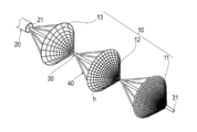
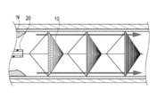
図1、図2A及び図2Bは、本発明の実施形態に係る医療器具100を示す図である。
医療器具100は、脳梗塞等の手技において狭窄部を拡張する際に生じるデブリス(Debris)が遠位側に流通して抹消側の血管に塞栓が生じることを防止するデバイス(EPD:Embolic Protection Device)である。
本実施形態に係る医療器具100は、図1を参照して概説すれば、狭窄部の拡張等の手技において発生するデブリスが抹消へ流通することを防止するフィルタ10と、フィルタ10を収容可能なカテーテル20と、を有する。医療器具100は、フィルタ10を複数並べて配置する長尺状のシャフト部材30と、シャフト部材30及びフィルタ10に取り付けられフィルタ10を拡張した状態及び収縮した状態に変化可能なフレーム部材40と、を有する。
なお、本明細書では医療器具100を直線状に伸ばした状態における医療器具100の伸延方向を長手方向と定義する。また、長手方向において、血管(「生体管腔」に相当)に挿入される側を先端側(図1の左側)と定義し、反対側を基端側(図1の右側)と定義する。また、医療器具100及び医療器具100を構成する部材の長手方向において略半分の位置よりも先端側の部分を先端部と定義し、基端側の部分を基端部と定義する。また、血管において、医療器具100を押し込んで挿入する方向を挿入方向Xと定義する(図5参照)。また、血管において、挿入方向Xの奥側を遠位側と定義し、挿入方向Xの手前側を近位側と定義する。以下、詳述する。
(カテーテル)
カテーテル20は、図1に示すように、可撓性を備える長尺状のシース21と、シース21の基端部に設けられるとともに、術者が把持して操作するためのハブ22と、を有している。以下、シース21の各部について説明する。
カテーテル20は、図1に示すように、可撓性を備える長尺状のシース21と、シース21の基端部に設けられるとともに、術者が把持して操作するためのハブ22と、を有している。以下、シース21の各部について説明する。
シース21は、可撓性を備える管状部材によって構成している。シース21は、全長に亘って内腔23が形成されている。内腔23は、図1に示すようにシャフト部材30の少なくとも一部を収容するとともに複数のフィルタ11、12、13を収縮した状態で収容可能に構成している。
シース21の構成材料としては、可撓性を備える材料である限り特に限定されないが、例えば、ポリエチレン、ポリプロピレン、ポリブテン、エチレン-プロピレン共重合体、エチレン-酢酸ビニル共重合体、アイオノマー、あるいはこれら二種以上の混合物等のポリオレフィンや、ポリ塩化ビニル樹脂、ポリアミド、ポリアミドエラストマー、ポリエステル、ポリエステルエラストマー、ポリウレタン、フッ素樹脂等を用いることができる。
シース21の先端部には、図1に示すように放射線透視下(X透視下)で視認可能なマーカ部24が設けられている。マーカ部24は、環状部材によって構成している。マーカ部24は、シース21の先端部に埋め込まれている。シース21の先端部にマーカ部24を設けることによって、放射線透視下におけるシース21の先端部の位置を容易に把握することができる。
マーカ部24の材料は、放射線透視下(X線不透過性)において視認可能な材料を含む限り特に限定されない。そのような材料としては、例えば、金、白金、タングステン等の金属、及びこれらを含む合金等の放射線不透過性の材料が挙げられる。
ハブ22は、円筒状の部材によって構成しており、全長に亘って内腔が形成されている。
ハブ22の構成材料は、特に限定されないが、例えば、スチレン系、ポリオレフィン系、ポリウレタン系、ポリエステル系、ポリアミド系、ポリブタジエン系、トランスポリイソプレン系、フッ素ゴム系、塩素化ポリエチレン系等の各種熱可塑性エラストマー、これらのうちの二種以上を組み合わせたもの(ポリマーアロイ、ポリマーブレンド、多層体等)を用いることができる。
(フィルタ)
フィルタ10は、シース21の内腔23に収縮した状態で収容され、内腔23から取り出した状態において拡張可能に構成している。フィルタ10は、図1、図2A等に示すようにシャフト部材30の長手方向に配置した第1フィルタ11、第2フィルタ12、及び第3フィルタ13を備える。第1フィルタ11は、図2Aに示すように第2フィルタ12及び第3フィルタ13よりも先端側に配置している。第2フィルタ12は、第3フィルタ13よりも先端側に配置している。
フィルタ10は、シース21の内腔23に収縮した状態で収容され、内腔23から取り出した状態において拡張可能に構成している。フィルタ10は、図1、図2A等に示すようにシャフト部材30の長手方向に配置した第1フィルタ11、第2フィルタ12、及び第3フィルタ13を備える。第1フィルタ11は、図2Aに示すように第2フィルタ12及び第3フィルタ13よりも先端側に配置している。第2フィルタ12は、第3フィルタ13よりも先端側に配置している。
フィルタ10は、図2Aに示すように複数の孔hを備える。本実施形態においてフィルタ10の複数の孔hは、フィルタ10に網目形状を設けることによって構成している。本実施形態において第1フィルタ11、第2フィルタ12、及び第3フィルタ13は、網の大きさを各々異ならせるように構成している。
第1フィルタ11は、図1、図2Aに示すように網目の大きさを第2フィルタ12及び第3フィルタ13よりも小さくなるように構成している。また、第2フィルタ12は第3フィルタ13よりも網目の大きさが小さくなるように構成している。
このように、フィルタ10では先端側に向かうにつれてフィルタの網目の大きさが小さくなるように構成している。言い換えれば、最基端に位置する第3フィルタ13の孔hの大きさは、他のフィルタである第1フィルタ11及び第2フィルタ12の孔hの大きさよりも大きく構成している。一例として第1フィルタ11、第2フィルタ12及び、第3フィルタ13のメッシュサイズは、各々40μm、100μm、IVC(Inferior Vena Cava)フィルタのメッシュサイズ程度である。
ただし、狭窄部から離脱したデブリスを捕捉して抹消器官へ流通することを阻害できれば、複数のフィルタにおける孔hの大きさの関係は上記に限定されない。
第1フィルタ11、第2フィルタ12、及び第3フィルタ13の拡張時の長手方向に直交する寸法d1(図2B参照)は、本実施形態において全て同一に構成している。また、第1フィルタ11と第2フィルタ12との間隔d2及び第2フィルタ12と第3フィルタ13との間隔d2は本実施形態において全て同一に構成している。
また、第1フィルタ11、第2フィルタ12、及び第3フィルタ13は、図2Bに示すように拡張時にデブリス等のフィルタリングする物質の収容空間V(収容部に相当)を形成する。収容空間Vを形成するフィルタ11、12、13は、本実施形態においてフィルタの形状が根元部14から外周縁部15にかけて広がるように、一例として略円錐形状に構成している。本実施形態において根元部14は、外周縁部15よりも先端側に位置するように配置している。収容空間Vの容積は、本実施形態では第1フィルタ11、第2フィルタ12、及び第3フィルタ13において全て同一に構成している。フィルタ10における収容空間Vは、本実施形態においてフィルタ10の放射方向内方であって、かつ、略円錐形状の先端部10bよりも基端側に形成されるように構成している。収容空間Vを形成する第1フィルタ11、第2フィルタ12、及び第3フィルタ13の外周縁部15は、図2Bに示すように側面視した際に外周縁部がシャフト部材30に対して直交するように構成している。
フィルタ10は、図2Bに示すような略円錐形状の側面を形成できるようにフィルタ10の基端部10aは後述するフレーム部材40に接続されている。一方、フィルタ10の先端部10bは、シャフト部材30に対して進退移動可能に構成している。
また、フィルタ10を構成する第1フィルタ11及び第3フィルタ13にはX線等の放射線透視下において部材の位置を視認できるようにマーカ(図示省略)を埋め込む等して設けている。マーカは、放射線透視下においてその位置を認識できる限り、材料は特に限定されない。一例として金、白金、タングステン等の金属、及びこれらを含む合金等の放射線不透過性材料を挙げることができる。
第1フィルタ11、第2フィルタ12、及び第3フィルタ13の材料は、例示すればニッケル-チタン鋼線、ピアノ線などの金属線、ポリアミドやフッ素樹脂等の比較的剛性の高い合成樹脂が挙げられる。
(シャフト部材)
シャフト部材30は、シース21に収容可能な長尺状の部材である。シャフト部材30は、フィルタ10を構成する第1フィルタ11、第2フィルタ12、及び第3フィルタ13を長手方向に並べて配置するように構成している。
シャフト部材30は、シース21に収容可能な長尺状の部材である。シャフト部材30は、フィルタ10を構成する第1フィルタ11、第2フィルタ12、及び第3フィルタ13を長手方向に並べて配置するように構成している。
また、図2Aに示すように第1フィルタ11よりも先端に位置する先端部31は、医療器具100を生体管腔の遠位側へ進めていく際のガイドワイヤのように機能させることができる。
また、シャフト部材30は、本実施形態において第1フィルタ11、第2フィルタ12、第3フィルタ13を略等間隔に配置している。シャフト部材30の材料について例示すれば、ステンレス鋼線、ピアノ線、高張力鋼線、超弾性金属線を挙げることができる。
(フレーム部材)
フレーム部材40は、図2Bに示すようにフィルタ10の略円錐形状の基端部10aを放射方向外方に変位できるようにフィルタ10及びシャフト部材30に接続される。フレーム部材40は、本実施形態において棒状部材によって構成している。フレーム部材40は、先端側の端部がフィルタ10における第1フィルタ11、第2フィルタ12、第3フィルタ13の各々の基端部10aの外周に固定されている。フレーム部材40は、フィルタ10に取り付ける端部と逆側の基端側端部30aがシャフト部材30に固定されている。
フレーム部材40は、図2Bに示すようにフィルタ10の略円錐形状の基端部10aを放射方向外方に変位できるようにフィルタ10及びシャフト部材30に接続される。フレーム部材40は、本実施形態において棒状部材によって構成している。フレーム部材40は、先端側の端部がフィルタ10における第1フィルタ11、第2フィルタ12、第3フィルタ13の各々の基端部10aの外周に固定されている。フレーム部材40は、フィルタ10に取り付ける端部と逆側の基端側端部30aがシャフト部材30に固定されている。
フレーム部材40は、基端側に向かうにつれシャフト部材30に接近するような形状を備えている。このように構成することでシャフト部材30が基端側に引かれるのに伴い、フレーム部材40は、シース21の先端に押され、フレーム部材40の先端が放射方向内方に変位する。フレーム部材40の先端が放射方向内方に変位するのに伴って拡張した状態のフィルタ10は放射方向内方に収縮し、シース21に収納可能な大きさとなる(図5参照)。このように、フレーム部材40は、拡張したフィルタ10をシース21に収納することを補助する。
フレーム部材40は、本実施形態においてフィルタ10の略円形状の外周において角度方向に略等間隔で取り付けるように構成している。ただし、狭窄部から離脱するデブリスを捕捉できれば、フィルタ10に対する複数のフレーム部材40の取り付け位置は角度方向に等間隔に限定されない。
また、本実施形態では、図2Aに示すようにフレーム部材40は、第1フィルタ11、第2フィルタ12、及び第3フィルタ13において各々角度方向に4つ配置するように構成している。ただし、狭窄部から離脱するデブリス等を捕捉できれば、ひとつのフィルタに取り付けるフレーム部材40の数は4つに限定されない。上記以外にも例えばフレーム部材40の数を2つとした場合、血管等の生体管腔にフィットしやすくできる。
なお、フィルタ10の基端側外周を放射方向外方に変位できれば、上記のようにフレーム部材40がフィルタ10の拡張を補助する場合とは別にフィルタ10自身が放射方向外方に拡張する材料、形状、又は構造を備えるように構成してもよい。また、フレーム部材40がフィルタ10を拡張させるだけでなく、フィルタ10自身も放射方向外方に拡張する材料、形状、又は構造を備えてもよい。
フレーム部材40の材料は、特に限定されないが、例示すれば、チタン系(Ti-Ni、Ti-Pd、Ti-Nb-Sn等)や銅系の形状記憶合金、アクリル系樹脂、トランスイソプレンポリマー、ポリノルボルネン、スチレン-ブタジエン共重合体、ポリウレタン等の形状記憶樹脂、ステンレス鋼(SUS304)、βチタン鋼、Co-Cr合金等のバネ性を備える合金を用いることができる。
(処置方法)
次に、頚動脈を一例に生体管腔に形成された狭窄部の処置方法について説明する。図3~図12は本実施形態に係る狭窄部の拡張方法の説明に供する図である。なお、本処置方法では、公知の医療器具として後述するようにバルーンカテーテル及びステントデリバリーシステムを使用する。
次に、頚動脈を一例に生体管腔に形成された狭窄部の処置方法について説明する。図3~図12は本実施形態に係る狭窄部の拡張方法の説明に供する図である。なお、本処置方法では、公知の医療器具として後述するようにバルーンカテーテル及びステントデリバリーシステムを使用する。
本実施形態に係る狭窄部の拡張方法について図3を参照して概説すれば、医療器具100を頚動脈に挿入し(ST1)、医療器具100のシース21からシャフト部材30を進出させ、フィルタ10を拡張させる(ST2)。続いて、バルーンカテーテルを狭窄部Nに配置してバルーンBを拡張し(ST3)、ステントSを留置する(ST4)。ステントSの留置後に狭窄部NでバルーンBを拡張させ、その後、フィルタ10を収縮させる(ST5)。そして、医療器具100を頚動脈から抜去する(ST6)。以下、詳述する。
まず、公知の穿刺針等を大腿動脈又は撓骨動脈等に穿刺して、医療器具100やバルーンカテーテル等の挿入部位を形成する。次に、イントロデューサー(図示省略)を上記挿入部位に配置し、医療器具100をイントロデューサーから大腿動脈又は橈骨動脈等に挿入する(ST1)。
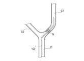
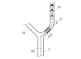
次に、血管造影等によって医療器具100の位置を確認しながら、医療器具100を図4に示す内頚動脈C1の近傍に進める。医療器具100の先端は、狭窄部Nの拡張に伴い、発生したプラーク等が脳血管等に流通しないように狭窄部Nを通過してより遠位側まで先端を進めておく。本実施形態において狭窄部Nは、図4に示すように総頚動脈Cよりも遠位側に位置する内頚動脈C1と外頚動脈C2のうちの内頚動脈C1に位置している。
医療器具100は、図5に示すようにフィルタ10をシース21に収容した状態にて生体管腔の狭窄部Nの近傍まで移動させる。図4に示すように医療器具100の先端が狭窄部Nを超えてより遠位側に達したら、フィルタ10をシース21から進出させる。これにより、フィルタ10の先端部10bが基端側に付勢されて先端部10bが生体管腔の内壁に接する程度に放射方向外方に変位し、図7に示すようにフィルタ10が放射方向外方に拡張するように変形する(ST2)。
フィルタ10が上記のように動作することによって、仮に後述するように基端側の第3フィルタ13においてデブリスDの溢れ、こぼれ、詰まり等が生じたとしても、第2フィルタ12や第1フィルタ11によって当該デブリスを捕捉し得る。
狭窄部Nよりも遠位側でフィルタ10が拡張したことを確認したら、シース21を基端側に後退させる。
次に、バルーンカテーテルを用いて狭窄部Nを拡張させる。バルーンカテーテルは、周知のように長尺状の中空部材の先端部にバルーンBが配置され、中空部材の内部空間から送られた流体によってバルーンBが拡張し、狭窄部Nを拡張させる。
本処置方法では、シャフト部材30に沿わせてバルーンカテーテルを穿刺部位から挿入し、内頚動脈C1の狭窄部Nまで進める。そして、インデフレーター等によって拡張流体をバルーンBに供給し、図8に示すように狭窄部NにてバルーンBを拡張させる(ST3)。
バルーンBを拡張させ、狭窄部Nに当接した際には狭窄部NからデブリスDが発生する可能性がある。このような場合であっても、バルーンBよりも遠位側に複数のフィルタを含むフィルタ10を配置することで、上記のように基端側の第3フィルタ13等に仮にデブリスDのこぼれ、溢れ、詰まり等が生じても先端側のフィルタにてデブリスを捕捉し得る。
バルーンBが一定程度拡張したことを確認したら、バルーンカテーテルをシャフト部材30に沿わせて基端側に移動させ、抜去する。
次に、ステントデリバリーシステムを用いて狭窄部を拡張した状態に保持する。
ステントデリバリーシステムは、自己拡張ステントの場合、長尺かつ中空のシースの内部空間に自己拡張ステントが放射方向に拡張可能な状態で収容されている。上記シースは基端側においてワイヤ等に接続され、牽引操作等によって収容されたステントSをシースから露出できるように構成している。
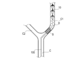
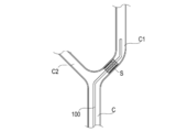
本処置方法では、まず、ステントデリバリーシステムを穿刺部位から挿入し、頚動脈等の狭窄部Nまで進める。次に、ステントデリバリーシステムの先端が狭窄部Nの手前付近まで到達したら、ステントSを被覆するシースを基端側に後退させてステントSを生体管腔において露出させる。これにより、ステントSが放射方向外方に拡張し、図9、図10に示すようにステントSによって狭窄部Nが拡張された状態に保持される(ST4)。
ステントSが拡張し、狭窄部Nに当接した際には狭窄部NからデブリスDが生じる可能性がある。このような場合においても、遠位側に複数のフィルタを含むフィルタ10を配置することで、基端側の第3フィルタ13等に仮にデブリスのこぼれ、溢れ、詰まり等が生じても先端側のフィルタにてデブリスを捕捉し得る。また、デブリスDを複数のフィルタに収容し得ることで、一つ一つのフィルタに収容されるデブリスDを少なくでき、デブリスDをフィルタ10からこぼれ難くできる。
ステントSを狭窄部Nで拡張させたら、ステントデリバリーシステムを基端側に移動させ、抜去する。
次に、バルーンカテーテルをシャフト部材30に沿わせて穿刺部位から再度挿入し、狭窄部Nまで移動させる。そして、拡張流体をバルーンBに供給し、図11に示すようにバルーンBによってステントSとともに狭窄部Nを再度拡張させる。この場合においてもバルーンBが拡張し、狭窄部Nに当接することによって、デブリスDが発生しうる。
これに対してフィルタ10を上記のように複数のフィルタから構成することで、仮に第3フィルタ13等の基端側のフィルタに溢れや詰まりが生じても先端側のフィルタにてデブリスDを捕捉することができる。
また、ステントSの拡張前のバルーンBの拡張、ステントSの拡張、及びステントSの拡張後のバルーンBの拡張の際に発生するデブリスDの形状や性質等は各々異なる可能性がある。そのような場合にも第1フィルタ11、第2フィルタ12、及び第3フィルタ13の孔hの大きさを変えることで様々な種類のデブリスDをも効果的に捕捉することができる。
バルーンBを一定程度拡張させたら、拡張流体を吸引してバルーンBを収縮させる。次に、バルーンカテーテルを基端側に移動させ、抜去する。
バルーンカテーテルを頚動脈から抜去したら、シース21を頚動脈において狭窄部Nまで前進させる。シース21の先端が狭窄部Nの近傍に到達したら、シャフト部材30を基端側に移動させ、図12に示すようにフィルタ10をシース21に接近させる。
フィルタ10を基端側に牽引すると、フィルタ10の先端部10bとフレーム部材40がシャフト部材30に接続された端部30aとの間隔が広がることで、フィルタ10の基端部10aの外周形状が放射方向内方に変位する。これにより、フィルタ10は、径方向の寸法d1(図2参照)がシース21に収容可能な大きさとなる。この状態で、フィルタ10が基端側に牽引されることでフィルタ10がシース21の内腔23に収容される(ST5)。
フィルタ10をシース21の内腔23に収容したら、シース21をフィルタ10とともに基端側に移動させる。そして、穿刺部位から医療器具100を抜去する(ST6)。
なお、上記処置方法において狭窄部Nは内頚動脈C1に形成されている場合を説明した。しかし、狭窄部Nは上記以外にも外頚動脈C2や総頚動脈Cに形成されていてもよい。
以上説明したように本実施形態に係る医療器具100は、頚動脈等の生体管腔に挿入可能な長尺状のシャフト部材30と、拡張収縮可能に構成され、シャフト部材30の長手方向に並べて配置された複数のフィルタ10と、を有する。これにより、一つのフィルタでは溢れ出るなどして捕捉の困難なデブリスを捕捉しやすくでき、デブリスの回収率を向上させることができる。また、フィルタ10を複数設けることによって、基端側のフィルタでは比較的大きめのデブリスを捕捉するとともに先端側のフィルタ10では比較的小さめのデブリスを捕捉する等ができ、フィルタの詰まりを起こりにくくすることができる。また、複数のフィルタ11、12、13の各フィルタは、複数の孔hを有し、複数のフィルタ11、12、13の内、最先端に位置するフィルタの孔hの大きさは他のフィルタの孔hの大きさよりも小さく構成している。そのため、近位側に位置する第2フィルタ12及び第3フィルタ13では溢れ出るなどして捕捉の困難なデブリスを捕捉する可能性を高めることができる。
また、複数のフィルタ10には、物質が捕捉される収容空間Vを備えるように構成している。そのため、狭窄部Nよりも抹消側に位置する脳血管等に狭窄部Nから脱離したデブリスが流通することを抑制又は防止できる。
また、複数のフィルタ10は、3つのフィルタから構成され、最基端に位置する第3フィルタ13の孔hの大きさは、他のフィルタである第1フィルタ11及び第2フィルタ12の孔hの大きさよりも大きく構成している。そのため、最基端に位置する第3フィルタ13にて比較的大きめのデブリスを捕捉して先端側のフィルタにおいてデブリスが溢れ出ることを抑制できる。
また、医療器具100はシャフト部材30を少なくとも一部収容するとともに複数のフィルタ10を収縮した状態で収容可能な内腔23を備えたシース21を備えるように構成している。そのため、狭窄部Nのようにフィルタ10を拡張させたままの状態では通過が困難な部位も医療器具100を容易に所望の部位へ移動させることができる。
また、複数のフィルタ11、12、13のうち、少なくとも一つはフィルタの根元部14から外周縁部15にかけて少なくとも一部が広がるように形成している。このように構成することによって、収縮した状態からのフィルタの拡張を容易にすることができる。
また、根元部14は、本実施形態において外周縁部15よりも先端側に位置するように構成している。このように構成することによって、本実施形態に係る医療器具100を内頚動脈C1等の生体管腔に配置した際に近位側から遠位側に向かって流通するデブリスを捕捉することができる。
なお、本発明は上述した実施形態にのみ限定されず、特許請求の範囲において種々の改変が可能である。上記では第1フィルタ11、第2フィルタ12、及び第3フィルタ13の孔hの大きさが異なる実施形態について説明したが、これに限定されない。上記以外にも孔hの大きさが複数のフィルタにおいて全て同じ大きさとなっていてもよい。
また、本発明に係る医療器具は、脳梗塞の手技に用いられる場合に限定されない。例えば、本発明に係る医療器具は、上記以外にも冠動脈や下肢等に対する処置に用いられてもよい。
また、上記実施形態では、フィルタ10の孔hが、メッシュ形状によって先端側の空間と基端側の空間を連通させる連通孔として機能する形態を説明した。ただし、上記以外にもメッシュでない素材のフィルタによって先端側の空間と基端側の空間を連通させるように構成してもよい。
また、フィルタ10の大きさの組み合わせは上記に限定されず、例えば複数のフィルタにおいて孔hの大きさが同じフィルタと異なるフィルタとが混在していてもよい。また、フィルタ10の孔hの大きさが少なくとも一部において異なる場合、孔hの大きさは先端から基端にかけて単調に増加又は減少していなくてもよい。
また、上記ではフィルタ11、12、13の外周縁部15が、フィルタを側面視した際にシャフト部材30と直交する実施形態について説明した。しかし、これに限定されず、上記以外にもフィルタの外周縁部は、フィルタを側面視した際にシャフト部材30と斜めに交差するように構成してもよい。
また、上記実施形態ではフィルタ10の形状を円錐形状とする実施形態について説明したが、これに限定されない。捕捉したデブリス等を収容する空間を形成できればフィルタの具体的な形状は上記以外にも以下のように構成することができる。
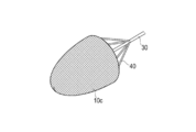
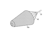
他の実施形態として、フィルタ10cの形状は、図13に示すように球体の一部をなすような側面形状とすることができる。また、他の実施形態としてフィルタ10dの形状は、図14に示すように略円筒形状として構成することができる。また、他の実施形態としてフィルタ10eの形状は、図15、図16に示すように略円錐台の形状を採用することができる。上記円錐台形状は、回転軸を中心に回転させることで形成してもよいし、図15、図16に示すように周方向に対称でない円錐台形状に構成してもよい。また、フィルタの形状は図2A等において全て円錐として形成したが、デブリス等を収容する空間を形成できれば、本発明に係る医療器具を構成する複数のフィルタはフィルタ毎に形状が異なっていてもよい。
また、上記では第1フィルタ11、第2フィルタ12、及び第3フィルタ13の拡張時の収容空間Vの容積が同一である実施形態について説明したが、これに限定されない。フィルタ10に捕捉されるデブリス等の量は狭窄部Nに近い程、多くなる可能性がある。そのため、フィルタの拡張時の収容空間Vの容積は先端側に近づくほど小さくなるように構成してもよい。
また、第1フィルタ11、第2フィルタ12、及び第3フィルタ13の拡張時の寸法d1は、全て同一である実施形態について説明した。ただし、寸法d1は、フィルタ毎に異なっていてもよい。そのため、第1フィルタ11、第2フィルタ12、及び第3フィルタ13は、遠位側に向かう程、フィルタ拡張時の寸法d1が小さくなるように構成してもよい。生体管腔は遠位側の方が血管径が細くなる可能性があるため、フィルタ拡張時の径を先端に向かう程小さくすることによって、血管等への負担を軽減することができる。
また、第1フィルタ11と第2フィルタ12との間隔d2は、第2フィルタ12と第3フィルタ13との間隔d2と同一であると説明した。ただし、脳血管へ流通し得るデブリスを効果的に捕捉できれば、第1フィルタ11と第2フィルタ12との間隔d2は第2フィルタ12と第3フィルタ13との間隔d2と同一でなくてもよい。例えば、第1フィルタ11と第2フィルタ12との間の間隔d2よりも、より遠位(先端)側に位置する第2フィルタ12と第3フィルタ13との間隔d2の方が大きくなるように構成してもよい。生体管腔は、遠位側の方が屈曲したりや蛇行したりする可能性が増える。そのため、上記のように構成することによって、先端側のフィルタを屈曲した血管等よりも遠位側に配置できることが期待できる。
このように構成することによって、例えば狭窄部Nよりも遠位側に第1フィルタ11と第2フィルタ12を配置した状態で第1フィルタ11と第2フィルタ12のみによってプラーク等を回収させることができる。
そして、その状態から第1フィルタ11と第2フィルタ12の収容空間Vにデブリス等が一定程度堆積したら、シース21から第3フィルタ13を進出させて第3フィルタ13を拡張させる。これにより、一旦は第1フィルタ11と第2フィルタ12のみによってプラーク等を回収した後に第1フィルタ11及び第2フィルタ12とともに第3フィルタ13にもデブリス等を回収させることができる。
また、上記実施形態では、医療器具がフィルタ10を収容可能なカテーテルを備える形態を説明した。ただし、必ずしも医療器具自体がカテーテルを備えなくてもよい。上記以外にも医療器具のフィルタは、狭窄部を通過可能な他のカテーテル(例えば、所謂マイクロカテーテルと呼ばれるもの)と組合せて使用してもよい。また、フィルタ10の拡張収縮は、上記のようにフィルタ10をシース21の先端から進出させる以外にも例えばバルーンによって拡張させることによって行ってもよい。
本出願は、2018年3月28日に出願された日本国特許出願2018-061800号に基づいており、その開示内容は参照により全体として引用される。
100 医療器具、
10 フィルタ、
11 第1フィルタ、
12 第2フィルタ、
13 第3フィルタ、
14 根元部、
15 外周縁部
21 シース、
23 内腔、
30 シャフト部材、
40 フレーム部材、
B バルーン、
C 総頚動脈、
C1 内頚動脈、
C2 外頚動脈、
D デブリス、
d1 フィルタの拡張時の放射方向の寸法、
d2 隣接するフィルタ同士の間隔
N 狭窄部、
S ステント、
V 収容空間(収容部)。
10 フィルタ、
11 第1フィルタ、
12 第2フィルタ、
13 第3フィルタ、
14 根元部、
15 外周縁部
21 シース、
23 内腔、
30 シャフト部材、
40 フレーム部材、
B バルーン、
C 総頚動脈、
C1 内頚動脈、
C2 外頚動脈、
D デブリス、
d1 フィルタの拡張時の放射方向の寸法、
d2 隣接するフィルタ同士の間隔
N 狭窄部、
S ステント、
V 収容空間(収容部)。
Claims (8)
- 生体管腔に挿入可能な長尺状のシャフト部材と、
拡張収縮可能に構成され、前記シャフト部材の長手方向に並べて配置された複数のフィルタと、を備え、
前記複数のフィルタの各フィルタは、複数の孔を有し、
前記複数のフィルタの内、最先端に位置するフィルタの孔の大きさは、他のフィルタの孔の大きさよりも小さい、ことを特徴とする医療器具。 - 複数の前記フィルタは、物質が捕捉される収容部を備える、請求項1に記載の医療器具。
- 前記複数のフィルタは、3つ以上のフィルタから構成され、最基端に位置するフィルタの孔の大きさは、他のフィルタの孔の大きさよりも大きい、請求項1又は2に記載の医療器具。
- 複数の前記フィルタの拡張時の大きさは、先端側に位置するフィルタほど小さくなる、請求項1~3のいずれか1項に記載の医療器具。
- 複数の前記フィルタにおいて隣接するフィルタ同士の間隔は、先端側に位置するフィルタ同士の方が大きくなる、請求項1~4のいずれか1項に記載の医療器具。
- 前記シャフト部材の少なくとも一部を収容するとともに複数の前記フィルタを収縮した状態で収容可能な内腔を備えたシースをさらに有する、請求項1~5のいずれか1項に記載の医療器具。
- 前記複数のフィルタの少なくとも一つは、根元部から外周縁部にかけて広がるように形成される、請求項1~6のいずれか1項に記載の医療器具。
- 前記根元部は、前記外周縁部よりも先端側に位置する、請求項7に記載の医療器具。
Applications Claiming Priority (2)
| Application Number | Priority Date | Filing Date | Title |
|---|---|---|---|
| JP2018-061800 | 2018-03-28 | ||
| JP2018061800A JP2021094041A (ja) | 2018-03-28 | 2018-03-28 | 医療器具 |
Publications (1)
| Publication Number | Publication Date |
|---|---|
| WO2019188705A1 true WO2019188705A1 (ja) | 2019-10-03 |
Family
ID=68059961
Family Applications (1)
| Application Number | Title | Priority Date | Filing Date |
|---|---|---|---|
| PCT/JP2019/011848 Ceased WO2019188705A1 (ja) | 2018-03-28 | 2019-03-20 | 医療器具 |
Country Status (2)
| Country | Link |
|---|---|
| JP (1) | JP2021094041A (ja) |
| WO (1) | WO2019188705A1 (ja) |
Citations (3)
| Publication number | Priority date | Publication date | Assignee | Title |
|---|---|---|---|---|
| US20070088383A1 (en) * | 2005-10-03 | 2007-04-19 | Cook Incorporated | Embolic protection device |
| US20140276922A1 (en) * | 2013-03-15 | 2014-09-18 | Cook Medical Technologies Llc | Shape memory metal emboli trap |
| JP2017507007A (ja) * | 2014-03-04 | 2017-03-16 | ライクマーク メディカル、インコーポレイテッドLikemark Medical, Inc. | 複数の血塊係合用要素を有する血管内血栓塞栓除去デバイス |
-
2018
- 2018-03-28 JP JP2018061800A patent/JP2021094041A/ja active Pending
-
2019
- 2019-03-20 WO PCT/JP2019/011848 patent/WO2019188705A1/ja not_active Ceased
Patent Citations (3)
| Publication number | Priority date | Publication date | Assignee | Title |
|---|---|---|---|---|
| US20070088383A1 (en) * | 2005-10-03 | 2007-04-19 | Cook Incorporated | Embolic protection device |
| US20140276922A1 (en) * | 2013-03-15 | 2014-09-18 | Cook Medical Technologies Llc | Shape memory metal emboli trap |
| JP2017507007A (ja) * | 2014-03-04 | 2017-03-16 | ライクマーク メディカル、インコーポレイテッドLikemark Medical, Inc. | 複数の血塊係合用要素を有する血管内血栓塞栓除去デバイス |
Also Published As
| Publication number | Publication date |
|---|---|
| JP2021094041A (ja) | 2021-06-24 |
Similar Documents
| Publication | Publication Date | Title |
|---|---|---|
| US11083559B2 (en) | Collection method | |
| AU2002352628B2 (en) | Stent delivery device with embolic protection | |
| US9254213B2 (en) | Stent delivery device | |
| US7594926B2 (en) | Methods, systems and devices for delivering stents | |
| JP2022504291A (ja) | 医療用インプラント送達システム | |
| JP6899452B2 (ja) | ステント送達システム | |
| JP7198272B2 (ja) | インプラント送達システム | |
| JP2004097807A (ja) | 血栓捕捉カテーテル | |
| US20160008025A1 (en) | Tissue collection device for catheter | |
| CN110662512B (zh) | 具有精细指轮控制和快速曲柄手柄的支架递送导管 | |
| JP2006305301A (ja) | 捕捉フィルタ及びそれを用いた捕捉装置 | |
| US20090112253A1 (en) | Guidewire for embolic device | |
| JP6686156B2 (ja) | 医療用デバイス及びステント送達システムを製造する方法 | |
| JP2021094041A (ja) | 医療器具 | |
| JP2019150316A (ja) | 医療器具 | |
| JP2019141302A (ja) | フィルタデバイス | |
| JP2017176277A (ja) | 医療用デバイス | |
| WO2025142412A1 (ja) | ステント | |
| AU2002340438A1 (en) | Stent delivery device | |
| AU2002363337A1 (en) | Stent delivery device with embolic protection |
Legal Events
| Date | Code | Title | Description |
|---|---|---|---|
| 121 | Ep: the epo has been informed by wipo that ep was designated in this application |
Ref document number: 19778300 Country of ref document: EP Kind code of ref document: A1 |
|
| NENP | Non-entry into the national phase |
Ref country code: DE |
|
| 122 | Ep: pct application non-entry in european phase |
Ref document number: 19778300 Country of ref document: EP Kind code of ref document: A1 |
|
| NENP | Non-entry into the national phase |
Ref country code: JP |