WO2019187816A1 - 移動体および移動体システム - Google Patents
移動体および移動体システム Download PDFInfo
- Publication number
- WO2019187816A1 WO2019187816A1 PCT/JP2019/006380 JP2019006380W WO2019187816A1 WO 2019187816 A1 WO2019187816 A1 WO 2019187816A1 JP 2019006380 W JP2019006380 W JP 2019006380W WO 2019187816 A1 WO2019187816 A1 WO 2019187816A1
- Authority
- WO
- WIPO (PCT)
- Prior art keywords
- image
- agv
- self
- moving
- position estimation
- Prior art date
Links
Images


Classifications
-
- G—PHYSICS
- G05—CONTROLLING; REGULATING
- G05D—SYSTEMS FOR CONTROLLING OR REGULATING NON-ELECTRIC VARIABLES
- G05D1/00—Control of position, course or altitude of land, water, air, or space vehicles, e.g. automatic pilot
- G05D1/02—Control of position or course in two dimensions
Definitions
- the present invention relates to a moving body and a moving body system.
- An autonomous mobile robot that moves autonomously along a predetermined route has been developed.
- the autonomous mobile robot senses the surrounding space using an external sensor such as a laser distance sensor, matches the sensing result with a map prepared in advance, and estimates (identifies) its current position and posture. .
- the autonomous mobile robot can move along the route while controlling its current position and posture.
- Japanese Unexamined Patent Application Publication No. 2016-99635 discloses an automatic driving system that travels on a preset traveling route and a driving support system that supports the operation of a driver.
- the vehicle's automatic driving system detects road surface indications such as lane markers and stop positions of roads around the host vehicle, detects three-dimensional objects such as multiple moving objects and obstacles around the host vehicle, and travels on the road To avoid collision with a three-dimensional object.
- the position of the host vehicle is specified by a predetermined method, and then the road surface display is detected and the three-dimensional object is detected to determine the traveling area on the road.
- One non-limiting exemplary embodiment of the present invention provides a technique for a mobile to estimate its own location.
- the mobile body in the exemplary embodiment of the present invention is a mobile body that can move autonomously, and a driving device that moves the mobile body, and repeatedly shooting the surrounding space while moving.
- a stereo camera that generates an environment image for each, a storage device that stores a plurality of reference images associated with each position in the space, and the environment image and the plurality of reference images
- a position estimation device that sequentially outputs position information of a position; and a controller that moves the moving body by controlling the driving device while referring to the position information output from the position estimation device.
- the apparatus extracts a plurality of feature points from the environment image, collates with the plurality of reference images, detects an image object included in the environment image, and uses the collation result and the detection result Estimating the self-position Te.
- the self-position is estimated using the image object in addition to the plurality of feature points included in the environment image. Since it is only necessary to acquire an environmental image, for example, the self-position can be estimated even in an indoor environment where GPS cannot be used. Further, by using the image object, it is possible to maintain the self-position estimation accuracy even when the number of feature points is small or the feature points greatly change.
- FIG. 1 is a block diagram showing a schematic configuration of a moving body in an exemplary embodiment of the present invention.
- FIG. 2 is a flowchart showing an outline of the operation of the moving object.
- FIG. 3 is a diagram showing an outline of a control system for controlling the running of each AGV according to the present invention.
- FIG. 4 is a diagram illustrating an example of the moving space S where the AGV exists.
- FIG. 5A is a diagram showing an AGV and a towing cart before being connected.
- FIG. 5B is a diagram showing connected AGVs and tow trucks.
- FIG. 6 is an external view of an exemplary AGV according to the present embodiment.
- FIG. 7A is a diagram illustrating a first hardware configuration example of AGV.
- FIG. 7B is a diagram illustrating a second hardware configuration example of AGV.
- FIG. 8A is a diagram illustrating an AGV that generates a map while moving.
- FIG. 8B is a diagram illustrating an AGV that generates a map while moving.
- FIG. 8C is a diagram illustrating an AGV that generates a map while moving.
- FIG. 8D is a diagram illustrating an AGV that generates a map while moving.
- FIG. 8E is a diagram illustrating an AGV that generates a map while moving.
- FIG. 8F is a diagram schematically showing a part of the completed map.
- FIG. 9 is a diagram illustrating an example in which a map of one floor is configured by a plurality of partial maps.
- FIG. 9 is a diagram illustrating an example in which a map of one floor is configured by a plurality of partial maps.
- FIG. 10 is a diagram illustrating a hardware configuration example of the operation management apparatus.
- FIG. 11 is a diagram schematically illustrating an example of the movement route of the AGV determined by the operation management device.
- FIG. 12 is a diagram illustrating a configuration of the AGV 10 according to an exemplary embodiment.
- FIG. 13A is a schematic diagram illustrating an example of an environment image 90 captured by the stereo camera 25 in the space 80 in which the AGV 10 travels.
- FIG. 13B is a schematic diagram illustrating an example in which the environment image 90 is divided into a feature point extraction target region 90A and an image object detection target region 90B.
- FIG. 14 is a diagram for explaining an AGV 10 that travels in a mixed manner of self-position estimation using feature points and self-position estimation using image objects.
- Automated guided vehicle means a trackless vehicle that loads a load on the body manually or automatically, automatically travels to the designated place, and unloads manually or automatically.
- Automated guided vehicle includes automatic guided vehicles and automatic forklifts.
- the term“ unmanned ” means that no person is required to steer the vehicle, and it does not exclude that the automated guided vehicle transports“ person (for example, a person who loads and unloads luggage) ”.
- Unmanned tow truck refers to a trackless vehicle that automatically pulls a cart that loads and unloads packages manually or automatically to a designated location.
- Unmanned forklift is a trackless vehicle equipped with a mast that moves up and down a load transfer fork, etc., automatically transfers the load to the fork, etc., automatically travels to the designated location, and performs automatic load handling work.
- a trackless vehicle is a vehicle that includes wheels and an electric motor or engine that rotates the wheels.
- a “moving body” is a device that carries a person or a load and moves, and includes a driving device such as a wheel, a biped or multi-legged walking device, and a propeller that generate driving force (traction) for movement.
- the term “mobile body” in the present invention includes not only a narrow automatic guided vehicle but also a mobile robot, a service robot, and a drone.
- Autonomous travel includes travel based on a command of an operation management system of a computer to which the automatic guided vehicle is connected by communication, and autonomous travel by a control device included in the automatic guided vehicle. Autonomous traveling includes not only traveling where the automated guided vehicle travels to a destination along a predetermined route, but also traveling following a tracking target. Moreover, the automatic guided vehicle may temporarily perform manual travel based on an instruction from the worker. “Automatic travel” generally includes both “guide type” travel and “guideless type” travel, but in the present invention, it means “guideless type” travel.
- “Guide type” is a method in which a derivative is installed continuously or intermittently and a guided vehicle is guided using the derivative.
- “Guideless type” is a method of guiding without installing a derivative.
- the automatic guided vehicle in the embodiment of the present invention includes a position estimation device that estimates its own position, and can travel in a guideless manner.
- the “position estimation device” is a device that estimates the self-position on the environmental map based on sensor data acquired by an external sensor such as a laser range finder.
- External sensor is a sensor that senses the external state of the moving body.
- Examples of the external sensor include a laser range finder (also referred to as a range sensor), a camera (or an image sensor), a LIDAR (Light Detection and Ranging), a millimeter wave radar, and a magnetic sensor.
- Internal sensor is a sensor that senses the internal state of a moving object.
- Examples of the internal sensor include a rotary encoder (hereinafter sometimes simply referred to as “encoder”), an acceleration sensor, and an angular acceleration sensor (for example, a gyro sensor).
- SAM Simultaneous Localization
- Mapping means that self-location estimation and environmental map creation are performed simultaneously.
- the moving object described in the present invention captures a surrounding space with a stereo camera, and uses a generated image (hereinafter referred to as “environment image”) and a plurality of reference images associated with each position in the space. To estimate the self-position.
- the “reference image” is an image of a space taken in advance.
- the moving body can move autonomously.
- An example of such a moving body is an automatic guided vehicle (for example, FIG. 6 described later).
- the moving body extracts a plurality of feature points from the environment image and collates them with a plurality of reference images. The collation is performed from the viewpoint of which reference image of the plurality of reference images the relationship between the plurality of feature points appears most frequently.
- the moving object further detects an image object included in the environment image.
- the image object is, for example, a sign drawn on the floor surface, and is a straight line, a dotted line, a symbol, a character, and / or a color defined as a lane, a median strip, a package destination, or the like.
- the moving body estimates its own position by using the matching result and the detection result. That is, the moving body can extract the feature point from the environment image and simultaneously estimate the self-position in consideration of the meaning of the image object included in the environment image.
- FIG. 1 is a block diagram showing a schematic configuration of a moving object in an exemplary embodiment of the present invention.
- the moving body 101 includes a stereo camera 103, a position estimation device 105, a storage device 106, a controller 107, and a drive device 109.
- the position estimation device 105 and the controller 107 are separate semiconductor integrated circuit chips.
- the position estimation device 105 and the controller 107 can be a single semiconductor integrated circuit chip.
- the driving device 109 includes a mechanism for moving the moving body 101.
- the drive device 109 may include, for example, at least one drive electric motor (hereinafter simply referred to as “motor”) and a motor control circuit that controls the motor.
- motor a drive electric motor
- motor control circuit that controls the motor.
- the stereo camera 103 repeatedly shoots the surrounding space according to the movement of the moving body 101 and generates an environment image for each shooting.
- the shooting interval is, for example, 100 milliseconds.
- the position estimation device 105 refers to the map stored in the storage device 106.
- the “map” is essentially a planar diagram visualized by reducing and symbolizing the state of the space in which the moving object 101 can move.
- a set of images of a space taken before the operation of the moving object 101 is sometimes referred to as a “map”.
- the reason why such a set of reference images is called a map is that each reference image is associated with each position in the space and includes a feature that can specify each position.
- the moving object 101 detects in which reference image the feature point of the captured environment image exists.
- the position associated with the image determined to have the feature points matched at a predetermined ratio or more is the current position of the moving object 101.
- such a set of reference images is regarded as a category of “map”.
- the position estimation device 105 extracts a plurality of feature points from the environment image output from the stereo camera 103, collates the extraction result with a set of reference images, and estimates the position and orientation of the moving object based on the collation result.
- the position estimation device 105 sequentially outputs information (referred to as “position information” in this specification) indicating the estimated position and orientation of the moving body.
- the controller 107 is, for example, a microcontroller unit (microcomputer) that is a semiconductor integrated circuit.
- the controller 107 controls the driving device 109 while referring to the position information output from the position estimation device 105 to move the moving body 101.
- the position estimation device 105 when the position estimation device 105 collates a plurality of feature points extracted from the environment image with a set of reference images, the position estimation device 105 outputs a reliability indicating the degree to which the two match.
- the controller 107 When the reliability becomes less than a predetermined threshold during traveling and the image object in the environmental image can be detected during traveling, the controller 107 does not use the matching result and does not use the image object of the environmental image. You may estimate a self-position using a detection result. Since the moving body 101 only needs to be able to acquire one environmental image, it can estimate its own position even in an indoor environment where GPS cannot be used. Further, the moving object 101 can maintain the estimation accuracy of the self-position by using the image object even when the number of feature points is small or the feature points greatly change.
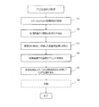
- FIG. 2 is a flowchart showing an outline of the operation of the exemplary mobile object 101 of the present invention.
- the process according to the flowchart shows the procedure of the process originally executed by a certain CPU, MPU, or microcontroller.
- the flowchart of FIG. 2 shows the processing of the position estimation apparatus 105 and the controller 107 mixed for convenience of understanding.
- the position estimation device 105 and the controller 107 execute each process while exchanging data with each other.
- Steps S1 to S5 are processing of the position estimation device 105.
- Step S ⁇ b> 6 is a process of the controller 107.
- step S1 the position estimation apparatus 105 receives an environment image generated every time the stereo camera 103 repeatedly shoots the surrounding space.
- the position estimation apparatus 105 extracts a plurality of feature points from the environment image in step S2.
- the feature point is, for example, an edge in the image. Since the stereo camera 103 can also acquire depth information based on compound eye parallax information, if the depth differs before and after the edge or right and left, the edge can be determined to be a boundary line of an object existing in the space.
- step S3 the position estimation apparatus 105 collates the plurality of feature points with each of the plurality of reference images. For example, the position estimation apparatus 105 collates to which reference image of the plurality of reference images the relationship that the extracted feature points have most frequently appears. The position estimation apparatus 105 outputs the degree of coincidence as “coincidence”. In addition, since it takes time to process a plurality of feature points and all the reference images every time, the range to be verified may be limited to a part of the reference images.
- step S4 the position estimation device 105 detects an image object from the environment image. Examples of image objects are as described above.
- step S5 the position estimation device 105 estimates the self-position using the collation result in step S3 and / or the detection result in step S4, and outputs position information.
- step S6 the controller 107 starts the position information output from the position estimation device 105 and drives the driving device 109 toward the designated destination to move the moving body 101.
- step S6 is included for convenience of understanding and is not essential for the position identification process itself. Therefore, in FIG. 2, step S6 is indicated by a broken line.
- the mobile unit 101 may have a communication circuit, and obtain the latest reference image from the outside via this communication circuit.
- the communication circuit receives the updated reference image from an external device, for example, an operation management device described later.
- the moving body according to the present invention is an automatic guided vehicle
- the automatic guided vehicle may be described as “AGV” using an abbreviation.
- AGV automatic guided vehicle
- FIG. 3 shows a basic configuration example of an exemplary mobile management system 100 according to the present invention.
- the mobile management system 100 includes at least one AGV 10 and an operation management device 50 that manages the operation of the AGV 10.
- FIG. 3 also shows a terminal device 20 operated by the user 1.
- AGV10 is an automatic guided vehicle that can perform “guideless” traveling that does not require a magnetic tape or other derivative for traveling.
- the AGV 10 can perform self-position estimation and transmit the estimation result to the terminal device 20 and the operation management device 50.
- the AGV 10 can automatically travel in the moving space S in accordance with a command from the operation management device 50.
- the AGV 10 is further capable of operating in a “tracking mode” in which it moves following a person or other moving body.
- the operation management device 50 is a computer system that tracks the position of each AGV 10 and manages the running of each AGV 10.
- the operation management device 50 may be a desktop PC, a notebook PC, and / or a server computer.
- the operation management device 50 communicates with each AGV 10 via the plurality of access points 2. For example, the operation management apparatus 50 transmits the data of the coordinates of the position where each AGV 10 should go next to each AGV 10.
- Each AGV 10 transmits data indicating its own position and orientation to the operation management device 50 periodically, for example, every 100 milliseconds.
- the operation management device 50 transmits data on the coordinates of the position to be further headed.
- the AGV 10 can travel in the moving space S according to the operation of the user 1 input to the terminal device 20.
- An example of the terminal device 20 is a tablet computer.
- the travel of the AGV 10 using the terminal device 20 is performed at the time of map creation, and the travel of the AGV 10 using the operation management device 50 is performed after the map creation.
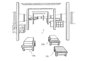
- FIG. 4 shows an example of a moving space S in which three AGVs 10a, 10b, and 10c exist. Assume that all AGVs are traveling in the depth direction in the figure. The AGVs 10a and 10b are transporting loads placed on the top board. The AGV 10c travels following the front AGV 10b.
- reference numerals 10a, 10b, and 10c are assigned in FIG. 4, but are hereinafter referred to as “AGV10”.
- the AGV 10 can also transport packages using a tow truck connected to itself, in addition to a method of transporting packages placed on the top board.
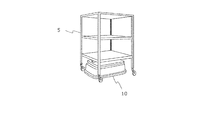
- FIG. 5A shows the AGV 10 and the traction cart 5 before being connected. A caster is provided on each foot of the traction cart 5. The AGV 10 is mechanically connected to the traction cart 5.
- FIG. 5B shows the AGV 10 and the traction cart 5 connected. When the AGV 10 travels, the tow cart 5 is pulled by the AGV 10. By pulling the tow cart 5, the AGV 10 can transport the load placed on the tow cart 5.
- connection method between the AGV 10 and the towing cart 5 is arbitrary.
- a plate 6 is fixed to the top plate of the AGV 10.
- the pulling cart 5 is provided with a guide 7 having a slit.
- the AGV 10 approaches the tow truck 5 and inserts the plate 6 into the slit of the guide 7.
- the AGV 10 passes an electromagnetic lock pin (not shown) through the plate 6 and the guide 7 and applies an electromagnetic lock. Thereby, AGV10 and tow cart 5 are physically connected.
- Each AGV 10 and the terminal device 20 can be connected, for example, on a one-to-one basis, and can perform communication based on the Bluetooth (registered trademark) standard.
- Each AGV 10 and the terminal device 20 can perform communication based on Wi-Fi (registered trademark) using one or a plurality of access points 2.
- the plurality of access points 2 are connected to each other via, for example, the switching hub 3.
- FIG. 3 shows two access points 2a and 2b.
- the AGV 10 is wirelessly connected to the access point 2a.
- the terminal device 20 is wirelessly connected to the access point 2b.
- the data transmitted by the AGV 10 is received by the access point 2a, transferred to the access point 2b via the switching hub 3, and transmitted from the access point 2b to the terminal device 20.
- the data transmitted by the terminal device 20 is received by the access point 2b, transferred to the access point 2a via the switching hub 3, and transmitted from the access point 2a to the AGV 10. Thereby, bidirectional communication between the AGV 10 and the terminal device 20 is realized.
- the plurality of access points 2 are also connected to the operation management device 50 via the switching hub 3. Thereby, bidirectional communication is also realized between the operation management device 50 and each AGV 10.
- a map in the moving space S is created so that the AGV 10 can travel while estimating its own position.
- the AGV 10 is equipped with a position estimation device and a laser range finder, and a map can be created using the output of the laser range finder.
- the AGV10 shifts to a data acquisition mode by a user operation.
- the AGV 10 starts acquiring sensor data using the laser range finder.
- the laser range finder periodically scans the surrounding moving space S by periodically emitting, for example, an infrared or visible laser beam.
- the laser beam is reflected by the surface of a structure such as a wall or a pillar or an object placed on the floor.
- the laser range finder receives the reflected light of the laser beam, calculates the distance to each reflection point, and outputs measurement result data indicating the position of each reflection point.
- the direction and distance of the reflected light are reflected at the position of each reflection point.
- the measurement result data may be referred to as “measurement data” or “sensor data”.
- the position estimation device accumulates sensor data in a storage device.
- the sensor data accumulated in the storage device is transmitted to the external device.
- the external device is, for example, a computer having a signal processor and having a mapping program installed therein.
- the signal processor of the external device superimposes the sensor data obtained for each scan.
- a map of the moving space S can be created by repeatedly performing the process of overlapping by the signal processor.
- the external device transmits the created map data to the AGV 10.
- the AGV 10 stores the created map data in an internal storage device.
- the external device may be the operation management device 50 or another device.
- the AGV 10 may create the map instead of the external device.
- the processing performed by the signal processor of the external device described above may be performed by a circuit such as a microcontroller unit (microcomputer) of the AGV 10.
- a map is created in the AGV 10
- the data capacity of sensor data is generally considered large. Since it is not necessary to transmit sensor data to an external device, occupation of the communication line can be avoided.
- the movement in the movement space S for acquiring sensor data can be realized by the AGV 10 traveling according to the user's operation.
- the AGV 10 receives a travel command instructing movement in the front, rear, left, and right directions from the user via the terminal device 20 wirelessly.
- the AGV 10 travels forward and backward, left and right in the movement space S according to the travel command, and creates a map.
- the AGV 10 may travel in the moving space S in the front / rear and left / right directions according to a control signal from the steering device to create a map.
- Sensor data may be acquired by a person walking around a measurement carriage equipped with a laser range finder.
- FIG 3 and 4 show a plurality of AGVs 10, one AGV may be used.
- the user 1 selects one AGV 10 from the plurality of registered AGVs using the terminal device 20, and creates a map of the moving space S in the selected AGV 10. Can be made.
- each AGV 10 can automatically travel while estimating its own position using the map. A description of the process of estimating the self position will be given later.
- FIG. 6 is an external view of an exemplary AGV 10.
- the AGV 10 includes two drive wheels 11a and 11b, four casters 11c, 11d, 11e, and 11f, a frame 12, a transport table 13, a travel control device 14, and a laser range finder 15.
- the two drive wheels 11a and 11b are provided on the right side and the left side of the AGV 10, respectively.
- the four casters 11c, 11d, 11e, and 11f are arranged at the four corners of the AGV 10.
- the AGV 10 also has a plurality of motors connected to the two drive wheels 11a and 11b, but the plurality of motors are not shown in FIG. FIG.
- FIG. 6 shows one drive wheel 11a and two casters 11c and 11e located on the right side of the AGV 10, and a caster 11f located on the left rear part.
- the caster 11d is not clearly shown because it is hidden behind the frame 12.
- the four casters 11c, 11d, 11e, and 11f can freely turn.
- the drive wheels 11a and the drive wheels 11b are also referred to as wheels 11a and wheels 11b, respectively.
- the AGV 10 further includes at least one obstacle sensor 19 for detecting an obstacle.
- the obstacle sensor 19 may be a device capable of measuring a distance, such as an infrared sensor, an ultrasonic sensor, or a stereo camera.
- the obstacle sensor 19 is an infrared sensor, for example, an obstacle that exists within a certain distance is detected by emitting an infrared ray every fixed time and measuring the time until the reflected infrared ray returns. Can do.
- the AGV 10 detects an obstacle on the path based on the signal output from the at least one obstacle sensor 19, the AGV 10 performs an operation to avoid the obstacle.
- the operation of avoiding the obstacle is, for example, an operation of moving while avoiding the obstacle.
- the traveling control device 14 is a device that controls the operation of the AGV 10, and mainly includes an integrated circuit including a microcomputer (described later), electronic components, and a board on which they are mounted.
- the traveling control device 14 performs the above-described data transmission / reception with the terminal device 20 and the preprocessing calculation.
- the laser range finder 15 is an optical instrument that measures the distance to the reflection point by, for example, emitting an infrared or visible laser beam 15a and detecting the reflected light of the laser beam 15a.
- the laser range finder 15 of the AGV 10 radiates a pulsed laser beam 15a while changing the direction every 0.25 degrees, for example, in a space of 135 degrees left and right (total 270 degrees) with respect to the front of the AGV 10, The reflected light of each laser beam 15a is detected. Thereby, data of the distance to the reflection point in the direction determined by the angle corresponding to the total of 1081 steps every 0.25 degrees can be obtained.
- the scanning of the surrounding space performed by the laser range finder 15 is substantially parallel to the floor surface and is planar (two-dimensional). However, the laser range finder 15 may perform scanning in the height direction.
- the AGV 10 can create a map of the moving space S based on the position and orientation (orientation) of the AGV 10 and the scan result of the laser range finder 15.
- the map may reflect the arrangement of walls, pillars and other structures around the AGV, and objects placed on the floor.
- the map data is stored in a storage device provided in the AGV 10.
- the position and posture of the moving body are called poses.
- the position and orientation of the moving body in the two-dimensional plane are expressed by position coordinates (x, y) in the XY orthogonal coordinate system and an angle ⁇ with respect to the X axis.
- the position and posture of the AGV 10, that is, the pose (x, y, ⁇ ) may be simply referred to as “position” hereinafter.
- the position of the reflection point viewed from the radiation position of the laser beam 15a can be expressed using polar coordinates determined by the angle and the distance.
- the laser range finder 15 outputs sensor data expressed in polar coordinates. However, the laser range finder 15 may convert the position expressed in polar coordinates into orthogonal coordinates and output the result.
- Examples of objects that can be detected by the laser range finder 15 are people, luggage, shelves, and walls.
- the laser range finder 15 is an example of an external sensor for sensing the surrounding space and acquiring sensor data.
- Other examples of such an external sensor include an image sensor and an ultrasonic sensor.
- the traveling control device 14 can estimate the current position of the AGV 10 by comparing the measurement result of the laser range finder 15 with the map data held by itself.
- the stored map data may be map data created by another AGV 10.
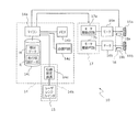
- FIG. 7A shows a first hardware configuration example of the AGV 10.
- FIG. 7A also shows a specific configuration of the travel control device 14.
- the AGV 10 includes a travel control device 14, a laser range finder 15, two motors 16a and 16b, a drive device 17, wheels 11a and 11b, and two rotary encoders 18a and 18b.
- the traveling control device 14 includes a microcomputer 14a, a memory 14b, a storage device 14c, a communication circuit 14d, and a position estimation device 14e.
- the microcomputer 14a, the memory 14b, the storage device 14c, the communication circuit 14d, and the position estimation device 14e are connected by a communication bus 14f and can exchange data with each other.
- the laser range finder 15 is also connected to the communication bus 14f via a communication interface (not shown), and transmits measurement data as a measurement result to the microcomputer 14a, the position estimation device 14e, and / or the memory 14b.
- the microcomputer 14a is a processor or a control circuit (computer) that performs calculations for controlling the entire AGV 10 including the travel control device 14.
- the microcomputer 14a is a semiconductor integrated circuit.
- the microcomputer 14a transmits a PWM (Pulse Width Modulation) signal, which is a control signal, to the drive device 17 to control the drive device 17 and adjust the voltages applied to the motors 16a and 16b. As a result, each of the motors 16a and 16b rotates at a desired rotation speed.
- PWM Pulse Width Modulation
- One or more control circuits for example, a microcomputer for controlling the driving of the left and right motors 16a and 16b may be provided independently of the microcomputer 14a.
- the driving device 17 may include two microcomputers that control driving of the motors 16a and 16b, respectively. These two microcomputers may perform coordinate calculations using the encoder information output from the rotary encoders 18a and 18b, respectively, and estimate the moving distance of the AGV 10 from a predetermined initial position.
- the two microcomputers may control the motor drive circuits 17a and 17b using encoder information.
- the memory 14b is a volatile storage device that stores a computer program executed by the microcomputer 14a.
- the memory 14b can also be used as a work memory when the microcomputer 14a and the position estimation device 14e perform calculations.
- the storage device 14c is a non-volatile semiconductor memory device.
- the storage device 14c may be a magnetic recording medium typified by a hard disk or an optical recording medium typified by an optical disk.
- the storage device 14c may include a head device for writing and / or reading data on any recording medium and a control device for the head device.
- the storage device 14c stores map data M of the traveling space S in which the vehicle travels, and data (travel route data) R of one or more travel routes.
- the map data M is created by the AGV 10 operating in the map creation mode and stored in the storage device 14c.
- the travel route data R is transmitted from the outside after the map data M is created.
- the map data M and the travel route data R are stored in the same storage device 14c, but may be stored in different storage devices.
- the AGV 10 receives travel route data R indicating a travel route from the tablet computer.
- the travel route data R at this time includes marker data indicating the positions of a plurality of markers. “Marker” indicates the passing position (via point) of the traveling AGV 10.
- the travel route data R includes at least position information of a start marker indicating a travel start position and an end marker indicating a travel end position.
- the travel route data R may further include position information of one or more intermediate waypoint markers. When the travel route includes one or more intermediate waypoints, a route from the start marker to the end marker via the travel route point in order is defined as the travel route.
- the data of each marker may include data on the direction (angle) and traveling speed of the AGV 10 until moving to the next marker, in addition to the coordinate data of the marker.
- the data of each marker includes acceleration time required for acceleration to reach the travel speed, and / or Further, it may include data of deceleration time required for deceleration from the traveling speed until the vehicle stops at the position of the next marker.
- the operation management device 50 (for example, a PC and / or a server computer) instead of the terminal device 20 may control the movement of the AGV 10. In that case, the operation management device 50 may instruct the AGV 10 to move to the next marker every time the AGV 10 reaches the marker. For example, the AGV 10 receives, from the operation management device 50, the coordinate data of the target position to be next, or the data of the distance to the target position and the angle to travel as the travel route data R indicating the travel route.
- the AGV 10 can travel along the stored travel route while estimating its own position using the created map and the sensor data output from the laser range finder 15 acquired during travel.
- the communication circuit 14d is a wireless communication circuit that performs wireless communication based on, for example, Bluetooth (registered trademark) and / or Wi-Fi (registered trademark) standards. Each standard includes a wireless communication standard using a frequency of 2.4 GHz band. For example, in a mode in which the AGV 10 is run to create a map, the communication circuit 14d performs wireless communication based on the Bluetooth (registered trademark) standard and communicates with the terminal device 20 one-on-one.
- Bluetooth registered trademark
- Wi-Fi registered trademark
- the position estimation device 14e performs map creation processing and self-position estimation processing when traveling.
- the position estimation device 14e creates a map of the moving space S based on the position and orientation of the AGV 10 and the scan result of the laser range finder 15.
- the position estimation device 14e receives sensor data from the laser range finder 15 and reads map data M stored in the storage device 14c.
- the position estimation device 14e performs matching between the local map data (sensor data) created from the scan result of the laser range finder 15 and the map data M in a wider range, so that the self-position (x , y, ⁇ ).
- the position estimation device 14e generates “reliability” data representing the degree to which the local map data matches the map data M.
- Each data of the self position (x, y, ⁇ ) and the reliability can be transmitted from the AGV 10 to the terminal device 20 or the operation management device 50.
- the terminal device 20 or the operation management device 50 can receive each data of its own position (x, y, ⁇ ) and reliability and display it on a built-in or connected display device.
- the microcomputer 14a and the position estimation device 14e are separate components, but this is an example.
- the microcomputer 14a and the position estimation device 14e may be a single chip circuit or a semiconductor integrated circuit that can independently perform the operations of the microcomputer 14a and the position estimation device 14e.
- FIG. 7A shows a chip circuit 14g including the microcomputer 14a and the position estimation device 14e. Below, the example in which the microcomputer 14a and the position estimation apparatus 14e are provided independently is demonstrated.
- the two motors 16a and 16b are attached to the two wheels 11a and 11b, respectively, and rotate the wheels 11a and 11b. That is, the two wheels 11a and 11b are drive wheels, respectively.
- the motor 16a and the motor 16b are described as being motors for driving the right wheel (wheel 11a) and the left wheel (wheel 11b) of the AGV 10, respectively.
- the moving body 10 further includes an encoder unit 18 that measures the rotational positions or rotational speeds of the wheels 11a and 11b.
- the encoder unit 18 includes a rotary encoder 18a and a rotary encoder 18b.
- the rotary encoder 18a measures the rotation at any position of the power transmission mechanism from the motor 16a to the wheel 11a.
- the rotary encoder 18b measures the rotation at any position of the power transmission mechanism from the motor 16b to the wheel 11b.
- the encoder unit 18 transmits the signals acquired by the rotary encoders 18a and 18b to the microcomputer 14a.
- the microcomputer 14a may control the movement of the moving body 10 using the signal received from the encoder unit 18 as well as the signal received from the position estimation device 14e.
- the drive device 17 has motor drive circuits 17a and 17b for adjusting the voltage applied to each of the two motors 16a and 16b.
- Each of motor drive circuits 17a and 17b includes a so-called inverter circuit.
- the motor drive circuit 17a turns on or off the current flowing through the motor 16a by the PWM signal transmitted from the microcomputer 14a or the microcomputer in the motor drive circuit 17a, thereby adjusting the voltage applied to the motor 16a.
- the motor drive circuit 17b turns on or off the current flowing through the motor 16b by the PWM signal transmitted from the microcomputer 14a or the microcomputer in the motor drive circuit 17b, thereby adjusting the voltage applied to the motor 16b.
- FIG. 7B shows a second hardware configuration example of the AGV 10.
- the second hardware configuration example is different from the first hardware configuration example (FIG. 7A) in that it has a laser positioning system 14h and that the microcomputer 14a is connected to each component in a one-to-one relationship. To do.
- the laser positioning system 14 h includes a position estimation device 14 e and a laser range finder 15.
- the position estimation device 14e and the laser range finder 15 are connected by, for example, an Ethernet (registered trademark) cable. Each operation of the position estimation device 14e and the laser range finder 15 is as described above.
- the laser positioning system 14h outputs information indicating the pause (x, y, ⁇ ) of the AGV 10 to the microcomputer 14a.
- the microcomputer 14a has various general purpose I / O interfaces or general purpose input / output ports (not shown).
- the microcomputer 14a is directly connected to other components in the travel control device 14 such as the communication circuit 14d and the laser positioning system 14h via the general-purpose input / output port.
- the AGV 10 may include a safety sensor such as a bumper switch (not shown).
- the AGV 10 may include an inertial measurement device such as a gyro sensor.
- the AGV 10 can estimate the movement distance and the change amount (angle) of the AGV 10 by using measurement data obtained by an internal sensor such as the rotary encoders 18a and 18b or an inertial measurement device. These estimated values of distance and angle are called odometry data, and can exhibit a function of assisting position and orientation information obtained by the position estimation device 14e.
- FIGS. 8A, 8B, 8C, 8D, 8E, and 8F are diagrams schematically illustrating the AGV 10 that moves while acquiring sensor data.
- the user 1 may move the AGV 10 manually while operating the terminal device 20.
- the sensor data may be acquired by placing the unit including the traveling control device 14 shown in FIGS. 7A and 7B, or the AGV 10 itself on the carriage, and the user 1 pushing or checking the carriage by hand. .
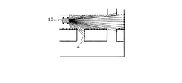
- FIG. 8A shows an AGV 10 that scans the surrounding space using the laser range finder 15.
- a laser beam is emitted at every predetermined step angle, and scanning is performed.
- the illustrated scan range is an example schematically shown, and is different from the above-described scan range of 270 degrees in total.
- the position of the reflection point of the laser beam is schematically shown using a plurality of black spots 4 represented by the symbol “ ⁇ ”.
- the laser beam scan is executed in a short cycle while the position and posture of the laser range finder 15 change. For this reason, the actual number of reflection points is much larger than the number of black spots 4 shown in the figure.
- the position estimation device 14e accumulates the position of the black spot 4 obtained as the vehicle travels, for example, in the memory 14b.
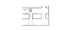
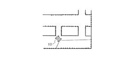
- the map data is gradually completed by continuously performing scanning while the AGV 10 is traveling. 8B to 8E, only the scan range is shown for the sake of simplicity.
- the scan range is an example, and is different from the above-described example of 270 degrees in total.
- the map may be created using the microcomputer 14a in the AGV 10 or an external computer on the basis of the sensor data after acquiring the amount of sensor data necessary for creating the map.
- the map may be created in real time based on sensor data acquired by the moving AGV 10.
- FIG. 8F is a diagram schematically showing a part of the completed map 40.
- the free space is partitioned by a point cloud (Point Cloud) corresponding to a collection of laser beam reflection points.
- Point Cloud Point Cloud
- Another example of the map is an occupied grid map that distinguishes between a space occupied by an object and a free space in units of grids.
- the position estimation device 14e accumulates map data (map data M) in the memory 14b or the storage device 14c.
- map data M map data M
- the number or density of black spots shown in the figure is an example.
- the map data obtained in this way can be shared by a plurality of AGVs 10.
- a typical example of an algorithm in which the AGV 10 estimates its own position based on map data is ICP (Iterative Closest Point) matching.
- ICP Intelligent Closest Point
- the AGV 10 matches the local map data (sensor data) created from the scan result of the laser range finder 15 with a wider range of map data M, so that the map data M is displayed on the map data M.
- the self position (x, y, ⁇ ) can be estimated.
- the map data M may be created and recorded separately for a plurality of partial map data.
- FIG. 9 shows an example in which the entire area of one floor of one factory is covered by a combination of four partial map data M1, M2, M3, and M4.
- one partial map data covers an area of 50 m ⁇ 50 m.
- a rectangular overlapping region having a width of 5 m is provided at the boundary between two adjacent maps in each of the X direction and the Y direction. This overlapping area is called a “map switching area”.
- the AGV 10 travels while referring to one partial map. When the AGV 10 reaches the map switching area, the AGV 10 switches to travel referring to another adjacent partial map.
- the number of partial maps is not limited to four, and may be set as appropriate according to the area of the floor on which the AGV 10 travels, the performance of the computer that executes map creation and self-position estimation.
- the size of the partial map data and the width of the overlapping area are not limited to the above example, and may be arbitrarily set.
- FIG. 10 shows a hardware configuration example of the operation management device 50.
- the operation management device 50 includes a CPU 51, a memory 52, a position database (position DB) 53, a communication circuit 54, a map database (map DB) 55, and an image processing circuit 56.
- the CPU 51, the memory 52, the position DB 53, the communication circuit 54, the map DB 55, and the image processing circuit 56 are connected by a bus 57 and can exchange data with each other.
- the CPU 51 is a signal processing circuit (computer) that controls the operation of the operation management device 50.
- the CPU 51 is a semiconductor integrated circuit.
- the memory 52 is a volatile storage device that stores a computer program executed by the CPU 51.
- the memory 52 can also be used as a work memory when the CPU 51 performs calculations.
- the position DB 53 stores position data indicating each position that can be a destination of each AGV 10.
- the position data can be represented by coordinates virtually set in the factory by an administrator, for example.
- the location data is determined by the administrator.
- the communication circuit 54 performs wired communication conforming to, for example, the Ethernet (registered trademark) standard.
- the communication circuit 54 is connected to the access point 2 (FIG. 3) by wire, and can communicate with the AGV 10 via the access point 2.
- the communication circuit 54 receives data to be transmitted to the AGV 10 from the CPU 51 via the bus 57.
- the communication circuit 54 transmits the data (notification) received from the AGV 10 to the CPU 51 and / or the memory 52 via the bus 57.
- the map DB 55 stores map data inside the factory where the AGV 10 is traveling.
- the map may be the same as or different from the map 40 (FIG. 8F).
- the map stored in the map DB 55 has a one-to-one correspondence with the position of each AGV 10, the data format is not limited.
- the map stored in the map DB 55 may be a map created by CAD.
- the position DB 53 and the map DB 55 may be constructed on a nonvolatile semiconductor memory, or may be constructed on a magnetic recording medium represented by a hard disk or an optical recording medium represented by an optical disk.
- the image processing circuit 56 is a circuit that generates video data to be displayed on the monitor 58.
- the image processing circuit 56 operates exclusively when the administrator operates the operation management device 50.
- the monitor 59 may be integrated with the operation management device 50. Further, the CPU 51 may perform the processing of the image processing circuit 56.
- FIG. 11 is a diagram schematically illustrating an example of the movement route of the AGV 10 determined by the operation management device 50.
- the outline of the operation of the AGV 10 and the operation management device 50 is as follows. In the following, an example will be described in which a certain AGV 10 is currently at the position M1, passes through several positions, and travels to the final destination position Mn + 1 (n: a positive integer of 1 or more).
- position DB 53 coordinate data indicating positions such as a position M2 to be passed next to the position M1, a position M3 to be passed next to the position M2, and the like are recorded.
- the CPU 51 of the operation management device 50 reads out the coordinate data of the position M2 with reference to the position DB 53, and generates a travel command for moving to the position M2.
- the communication circuit 54 transmits a travel command to the AGV 10 via the access point 2.
- the CPU 51 periodically receives data indicating the current position and posture from the AGV 10 via the access point 2.
- the operation management device 50 can track the position of each AGV 10.
- the CPU 51 determines that the current position of the AGV 10 coincides with the position M2
- the CPU 51 reads the coordinate data of the position M3, generates a traveling command to be directed to the position M3, and transmits it to the AGV 10.
- the operation management apparatus 50 transmits a travel command for directing to the position to be passed next.
- the AGV 10 can reach the final target position Mn + 1.
- the above-described passing position and target position of the AGV 10 may be referred to as “markers”.
- FIG. 12 shows the configuration of the AGV 10 according to the present embodiment.
- the stereo camera 25 is a camera that can record not only images but also information in the depth direction by simultaneously photographing an object from a plurality of different directions.
- the stereo camera 25 is two digital cameras arranged side by side at a distance of several centimeters to several tens of centimeters in the horizontal direction.
- the two digital cameras correspond to the right eye and the left eye of the stereo camera 25, and each has a lens and an image sensor that receives light incident on the lens.
- Each image sensor may be a CMOS image sensor or a CCD image that outputs an image signal.
- the stereo camera 25 includes an arithmetic circuit that calculates the parallax of the images of the left and right digital cameras taken in synchronization and calculates the distance to the subject corresponding to the parallax. Since the method for calculating the parallax is known, a specific description thereof will be omitted in this specification.
- FIG. 7B can also be adopted as the AGV 10 according to the present embodiment if the laser range finder 15 is changed to the stereo camera 25. Illustration of the AGV 10 having the stereo camera 25 corresponding to the configuration of FIG. 7B is omitted.
- AGV10 concerning this embodiment may have a stereo camera and a laser range finder. That is, this embodiment does not exclude the use of a laser range finder.
- the difference between the AGV 10 of FIG. 12 and the AGV 10 of FIG. 7A regarding the data is the substance of the map data M.
- the storage device 14c in FIG. 12 stores a plurality of reference images associated with each position in the space.
- Each reference image is an image obtained by photographing the space 80 (see FIG. 13A) in advance. Since the position at the time of shooting the reference image is known in advance, position information in the space 80 of each reference image can be associated with each reference image.
- FIG. 13A schematically shows an example of an environment image 90 taken by the stereo camera 25 in the space 80 where the AGV 10 travels.
- the environment image 90 illustrated is, for example, an image of the left eye of the stereo camera 25, and description of the right eye image is omitted.
- a broken-line rectangle in the drawing represents the range of the environment image 90, in other words, the visual field of the left eye of the stereo camera 25.
- FIG. 13A it is understood that there is a cabinet 82 and a desk 84 that is elongated in the depth direction.
- the position estimation device 14e of the AGV 10 receives the environment image 90 from the stereo camera 25 and analyzes the environment image 90.
- “Analysis” here is extraction of feature points and detection of image objects.
- the position estimation device 14e of the AGV 10 has an “image processing rule” in advance.
- the “image processing rule” includes a rule for extracting feature points and a rule for detecting image objects.
- the rule for extracting feature points is a rule for identifying both pixels in the environmental image 90 whose luminance difference between adjacent pixels is equal to or greater than a threshold value as feature points. More simply, the rule for extracting a feature point is a rule for making a pixel group constituting an “edge” in the environment image 90 a feature point.
- the feature points may be determined by other methods as long as the method is defined as a rule for extracting feature points.
- the rule for detecting an image object is a rule for identifying two parallel white lines as an image object.
- the system administrator means that two parallel white lines are marks on the traveling lane of the AGV 10 drawn on the floor surface of the space 80. Is given.
- a rule for detecting an image object a rule that a white dotted line between two parallel white lines is a median strip and a yellow straight line is a place where a load is placed is provided. You can also.
- the position estimation device 14e detects the pixel group as an image object when there is a pixel group that matches the rule for detecting the image object in the environment image 90.
- FIG. 13A shows a large number of extracted feature points represented by “ ⁇ ” (for example, reference numeral 91) and two parallel white line image objects 92A and 92B as analysis results.
- FIG. 13B schematically illustrates an example in which the environment image 90 is divided into a feature point extraction target region 90A and an image object detection target region 90B.
- the processing load can be reduced by limiting the region in which the environment image 90 is analyzed.
- “ ⁇ ” indicating a feature point is extracted in the area 90A, and the image objects 92A and 92B are detected in the area 90B.
- the region 90B is located below the region 90A. This is because the rule for detecting an image object assumes that a sign drawn on the floor is detected as an image object. Therefore, the positional relationship between the regions 90A and 90B can be determined according to the “image processing rule” described above. Further, the regions 90A and 90B may not be one and the other of the environment image 90 divided into two, or a plurality of regions 90A and / or 90B may be provided.
- the position estimation device 14e of the AGV 10 collates the extracted feature points with each of the plurality of reference images stored as the map data M in the storage device 14c. This will be described more specifically.
- the plurality of reference images are captured in advance and stored in the storage device 14c.
- the position estimation device 14e applies the above-described rule for extracting feature points to each reference image, and extracts the feature points in each reference image in advance.
- the position estimation apparatus 14e can collate the extracted feature points.
- the position estimation device 14e determines whether the positional relationship between the plurality of feature points in the environment image 90 has a large correlation with the positional relationship between the plurality of feature points in which reference image. As a result, the position estimation device 14e determines a reference image having a feature point having the largest correlation with the extracted feature point.
- the method for calculating the correlation is arbitrary.
- the magnitude of the correlation can be quantitatively evaluated by obtaining the magnitude of the correlation coefficient.
- the correlation coefficient between the feature point of the environment image 90 and the feature point of a certain reference image is obtained by dividing the covariance by the standard deviation of the feature point of the environment image 90 and by the standard deviation of the feature point of the reference image. It is required by doing.
- data representing feature points may be stored in the storage device 14c together with each reference image or instead of each reference image. This eliminates the need for the position estimation device 14e to extract the feature points of each reference image each time.
- the position estimation device 14e estimates that the position associated with the determined reference image is the current position of the AGV 10.
- the position estimation device 14e can estimate the self position from the meaning of the detected image object.
- data in which an image object is associated with a position in the space 80 is prepared in advance.
- the appearance and the position according to the appearance can be associated with each other.
- the position estimation device 14e can determine the position of the detected image object also by using the image object and the data.
- FIG. 14 is a diagram for explaining the AGV 10 that travels in a mixed manner of self-position estimation using feature points and self-position estimation using image objects.
- the AGV 10 is traveling in the right direction of the drawing.
- the position estimation device 14e of the AGV 10 may perform self-position estimation based on the image object, interpolate self-position estimation based on the feature points, and improve the position estimation accuracy.
- the processing of the position estimation device 14e at this time is represented by the flowchart shown in FIG. Therefore, the re-explanation is omitted.
- the reliability that is the degree of coincidence between the feature points of the environment image and the feature points of the reference image is set as a threshold because the walls 112 on both sides of the position P are monotonous. In some cases, the accuracy of self-position estimation decreases.
- a position can be known in advance. Therefore, for example, two white lines 114 are prepared at such positions, and a plurality of marks are given to the two white lines 114 according to the positions. The AGV 10 can detect each mark as the two white lines 114 are detected. If the data which linked
- the processing of the position estimation device 14e at this time means that steps S4 and S5 are executed as a result in the flowchart shown in FIG.
- the AGV 10 holds a set of reference images in advance, and estimates the current position by comparing the feature points of the image acquired by the stereo camera 25 with the feature points of each reference image.
- the present invention can be operated while the AGV 10 estimates its own position without preparing such a reference image in advance.
- the AGV 10 can calculate the relative movement amount of the AGV 10 from the previous shooting to the current shooting from the change in parallax. As long as the absolute coordinates for starting the movement are correctly given, the AGV 10 can move while accumulating the relative movement amount and grasping the current position. According to the above method, the present invention does not need to prepare a reference image in advance.
- the AGV 10 can be run according to the meaning.
- the image object is yellow, has a width of Xcm, and has a length of Ycm or more, it means that the image object is an area where a load is placed.
- the AGV 10 does not cross even if it stops near the area for unloading the load. Therefore, when the traveling AGV 10 detects an image object that meets the above-described conditions, the AGV 10 can travel so as not to cross a line corresponding to the image object during traveling.
- the comprehensive or specific aspect described above may be realized by a system, a method, an integrated circuit, a computer program, or a recording medium.
- the present invention may be realized by any combination of a system, an apparatus, a method, an integrated circuit, a computer program, and a recording medium.
- the exemplary mobile body and mobile system of the present invention can be suitably used for moving and transporting goods such as luggage, parts, and finished products in factories, warehouses, construction sites, logistics, hospitals, and the like.
Abstract
移動体が自己位置を推定する技術を提供する。自律的に移動することが可能な移動体(101)は、移動体を移動させる駆動装置(109)と、移動しながら周囲の空間を繰り返し撮影して撮影毎に環境画像を生成するステレオカメラ(103)と、各々が、空間の各位置に関連付けられた複数の基準画像を記憶する記憶装置(106)と、環境画像と複数の基準画像とを利用して、自己位置の位置情報を順次出力する位置推定装置(105)と、位置推定装置から出力された位置情報を参照しながら駆動装置を制御して、移動体を移動させるコントローラ(107)と、を有している。位置推定装置は、環境画像から複数の特徴点を抽出して複数の基準画像と照合し、かつ、環境画像に含まれる画像オブジェクトを検出し、照合結果および検出結果を利用して自己位置を推定する。
Description
本発明は移動体および移動体システムに関する。
所定の経路に沿って自律的に空間を移動する自律移動ロボットが開発されている。自律移動ロボットは、レーザ距離センサ等の外界センサを用いて周囲の空間をセンシングし、センシング結果と、予め用意された地図とのマッチングを行い、自身の現在の位置および姿勢を推定(同定)する。自律移動ロボットは、自身の現在の位置および姿勢を制御しながら、当該経路に沿って移動することができる。
特開2016-99635号公報は、予め設定された走行ルートを走行する自動運転システムやドライバの操作を支援する運転支援システムを開示する。車両の自動運転システムは、自車両周辺の道路のレーンマーカーや停止位置などの路面表示を検知し、自車両周辺の複数の移動体・障害物などの立体物を検知し、道路上の走行領域を判定して、立体物との衝突を回避する。
特開2016-99635号公報に記載の発明は、まず、所定の方法で自車両の位置を特定し、その後、路面表示の検知および立体物の検知を行い、道路上の走行領域を判定する。
本発明の、限定的ではない例示的なある実施形態は、移動体が自己位置を推定する技術を提供する。
本発明の例示的な実施形態における移動体は、自律的に移動することが可能な移動体であって、前記移動体を移動させる駆動装置と、移動しながら周囲の空間を繰り返し撮影して撮影毎に環境画像を生成するステレオカメラと、各々が、前記空間の各位置に関連付けられた複数の基準画像を記憶する記憶装置と、前記環境画像と前記複数の基準画像とを利用して、自己位置の位置情報を順次出力する位置推定装置と、前記位置推定装置から出力された位置情報を参照しながら前記駆動装置を制御して、前記移動体を移動させるコントローラと、を備え、前記位置推定装置は、前記環境画像から複数の特徴点を抽出して前記複数の基準画像と照合し、かつ、前記環境画像に含まれる画像オブジェクトを検出し、照合結果および検出結果を利用して前記自己位置を推定する。
本発明の実施形態によれば、環境画像に含まれる複数の特徴点に加え、画像オブジェクトも利用して自己位置を推定する。環境画像を取得できればよいので、例えばGPSが利用できない屋内等の環境であっても自己位置を推定することができる。また画像オブジェクトを利用することにより、特徴点が少ない、または、特徴点が大きく変動した場合でも、自己位置の推定精度を保つことができる。
<用語>
本発明の実施形態を説明する前に、本明細書において使用する用語の定義を説明する。
本発明の実施形態を説明する前に、本明細書において使用する用語の定義を説明する。
「無人搬送車」(AGV(Automated guided vehicle))とは、本体に人手または自動で荷物を積み込み、指示された場所まで自動走行し、人手または自動で荷卸しをする無軌道車両を意味する。「無人搬送車」は、無人牽引車および無人フォークリフトを含む。
「無人」の用語は、車両の操舵に人を必要としないことを意味しており、無人搬送車が「人(たとえば荷物の積み下ろしを行う者)」を搬送することは除外しない。
「無人牽引車」とは、人手または自動で荷物の積み込み荷卸しをする台車を牽引して、指示された場所まで自動走行する無軌道車両である。
「無人フォークリフト」とは、荷物移載用のフォークなどを上下させるマストを備え、フォークなどに荷物を自動移載し指示された場所まで自動走行し、自動荷役作業をする無軌道車両である。
「無軌道車両」とは、車輪と、車輪を回転させる電気モータまたはエンジンを備える移動体(vehicle)である。
「移動体」とは、人または荷物を載せて移動する装置であり、移動のための駆動力(traction)を発生させる車輪、二足または多足歩行装置、プロペラなどの駆動装置を備える。本発明における「移動体」の用語は、狭義の無人搬送車のみならず、モバイルロボット、サービスロボット、およびドローンを含む。
「自動走行」は、無人搬送車が通信によって接続されるコンピュータの運行管理システムの指令に基づく走行と、無人搬送車が備える制御装置による自律的走行とを含む。自律的走行には、無人搬送車が所定の経路に沿って目的地に向かう走行のみならず、追尾目標に追従する走行も含まれる。また、無人搬送車は、一時的に作業者の指示に基づくマニュアル走行を行ってもよい。「自動走行」は、一般には「ガイド式」の走行および「ガイドレス式」の走行の両方を含むが、本発明では「ガイドレス式」の走行を意味する。
「ガイド式」とは、誘導体を連続的または断続的に設置し、誘導体を利用して無人搬送車を誘導する方式である。
「ガイドレス式」とは、誘導体を設置せずに誘導する方式である。本発明の実施形態における無人搬送車は、自己の位置を推定する位置推定装置を備え、ガイドレス式で走行することができる。
「位置推定装置」は、レーザレンジファインダなどの外界センサによって取得されたセンサデータに基づいて環境地図上における自己位置を推定する装置である。
「外界センサ」は、移動体の外部の状態をセンシングするセンサである。外界センサには、たとえば、レーザレンジファインダ(測域センサともいう)、カメラ(またはイメージセンサ)、LIDAR(Light Detection and Ranging)、ミリ波レーダ、および磁気センサがある。
「内界センサ」は、移動体の内部の状態をセンシングするセンサである。内界センサには、たとえばロータリエンコーダ(以下、単に「エンコーダ」と称することがある)、加速度センサ、および角加速度センサ(たとえばジャイロセンサ)がある。
「SLAM(スラム)」とは、Simultaneous Localization and Mappingの略語であり、自己位置推定と環境地図作成を同時に行うことを意味する。
<例示的な実施形態>
以下、添付の図面を参照しながら、本発明にかかる移動体および移動体システムの一例を説明する。なお、必要以上に詳細な説明は省略する場合がある。たとえば、既によく知られた事項の詳細説明や実質的に同一の構成に対する重複説明を省略する場合がある。これは、以下の説明が不必要に冗長になるのを避け、当業者の理解を容易にするためである。本発明者らは、当業者が本発明を十分に理解するために添付図面および以下の説明を提供する。これらによって特許請求の範囲に記載の主題を限定することを意図するものではない。
以下、添付の図面を参照しながら、本発明にかかる移動体および移動体システムの一例を説明する。なお、必要以上に詳細な説明は省略する場合がある。たとえば、既によく知られた事項の詳細説明や実質的に同一の構成に対する重複説明を省略する場合がある。これは、以下の説明が不必要に冗長になるのを避け、当業者の理解を容易にするためである。本発明者らは、当業者が本発明を十分に理解するために添付図面および以下の説明を提供する。これらによって特許請求の範囲に記載の主題を限定することを意図するものではない。
本発明において説明する移動体は、ステレオカメラで周囲の空間を撮影し、生成した画像(以下「環境画像」と呼ぶ。)と、空間の各位置に関連付けられた複数の基準画像とを利用して自己位置を推定する。「基準画像」は、事前に撮影された空間の画像である。推定した自己位置を利用して、移動体は自律的に移動することが可能である。そのような移動体の例は、無人搬送車(例えば後述の図6)である。
より具体的に説明する。移動体は、環境画像から複数の特徴点を抽出して複数の基準画像と照合する。照合は、複数の特徴点が有する関係が、複数の基準画像のどの基準画像に最もよく現われているかの観点で行われる。移動体はさらに、環境画像に含まれる画像オブジェクトを検出する。画像オブジェクトは、例えば床面に描かれた標示であり、レーン、中央分離帯、荷物の搬送先等として定義される直線、点線、記号、文字および/または色である。移動体は、照合結果および検出結果を利用することにより、自己位置を推定する。つまり、移動体は、環境画像から特徴点を抽出し、同時に環境画像に含まれる画像オブジェクトの意味を考慮して、自己位置を推定することができる。
図1は、本発明の例示的な実施形態における移動体の概略構成を示すブロック図である。移動体101は、ステレオカメラ103と、位置推定装置105と、記憶装置106と、コントローラ107と、駆動装置109とを備えている。なお、ある実施形態では位置推定装置105およびコントローラ107は、それぞれ別個の半導体集積回路チップであるが、他の実施形態では、位置推定装置105およびコントローラ107は1つの半導体集積回路チップであり得る。
駆動装置109は、移動体101を移動させる機構を備えている。駆動装置109は、例えば少なくとも1台の駆動用電気モータ(以下、単に「モータ」と称する)、および、当該モータを制御するモータ制御回路を備え得る。
ステレオカメラ103は、移動体101の移動に応じて周囲の空間を繰り返し撮影して撮影毎に環境画像を生成する。撮影間隔は、例えば100ミリ秒である。
位置推定装置105は、記憶装置106に記憶された地図を参照する。「地図」とは、本来的には、移動体101が移動可能な空間の状況を、縮小し、記号化することで視覚化された平面的な線図である。しかしながら本明細書では、移動体101の動作開始前に撮影された空間の画像の集合を、「地図」と呼ぶことがある。このような基準画像の集合を地図と呼ぶ理由は、各基準画像が、空間内の各位置と関連付けられ、各位置を特定可能な特徴を含むからである。後述のように、移動体101は、撮影した環境画像の特徴点が、どの基準画像に存在するかを検出する。特徴点が所定以上の割合で一致したと判断された画像に関連付けられた位置が、移動体101の現在位置である。このような基準画像の集合を、本明細書では「地図」の範疇として捉える。
位置推定装置105は、ステレオカメラ103から出力された環境画像から複数の特徴点を抽出し、抽出結果と基準画像の集合とを照合し、照合結果に基づき移動体の位置および姿勢を推定する。位置推定装置105は、推定した移動体の位置および姿勢(orientation)を示す情報(本明細書において「位置情報」と称する)を順次出力する。
コントローラ107は、例えば、半導体集積回路であるマイクロコントローラユニット(マイコン)である。コントローラ107は、位置推定装置105から出力された位置情報を参照しながら駆動装置109を制御して、移動体101を移動させる。
本実施形態では、位置推定装置105は、環境画像から抽出された複数の特徴点と、基準画像の集合とを照合した際、両者が一致した程度を示す信頼度を出力する。コントローラ107は、走行中に当該信頼度が予め定められた閾値未満になり、かつ、環境画像中の画像オブジェクトが検出可能である場合には、照合結果を利用せず、環境画像の画像オブジェクトの検出結果を利用して自己位置を推定してもよい。移動体101は、1枚の環境画像を取得できればよいので、例えばGPSが利用できない屋内等の環境であっても自己位置を推定することができる。また、移動体101は、画像オブジェクトを利用することにより、特徴点が少ない、または、特徴点が大きく変動した場合でも、自己位置の推定精度を保つことができる。
図2は、本発明の例示的な移動体101の動作の概要を示すフローチャートである。フローチャートによる処理は、本来、ある1つのCPU、MPUまたはマイクロコントローラによって実行される処理の手順を示している。しかしながら図2のフローチャートは、理解の便宜のため、位置推定装置105およびコントローラ107の処理を混在させて示している。位置推定装置105およびコントローラ107は、互いにデータの授受を行いながら、各々の処理を実行する。ステップS1~S5は位置推定装置105の処理である。ステップS6はコントローラ107の処理である。
ステップS1において、位置推定装置105は、ステレオカメラ103が周囲の空間を繰り返し撮影して撮影毎に生成した環境画像を受け取る。位置推定装置105は、ステップS2において、環境画像から複数の特徴点を抽出する。特徴点は、例えば画像内のエッジである。ステレオカメラ103は、複眼の視差情報によって奥行きの情報も取得できるため、エッジの前後または左右で奥行きが異なる場合には、当該エッジを、空間内に存在する物の境界線であると判断できる。
ステップS3において、位置推定装置105は、複数の特徴点と、複数の基準画像の各々とを照合する。例えば位置推定装置105は、抽出された複数の特徴点が有する関係が、複数の基準画像のどの基準画像に最もよく現われているかを照合する。位置推定装置105は、両者が一致する程度を、「一致度」として出力する。なお、複数の特徴点と全ての基準画像とを毎回照合すると処理に時間を要するため、照合する範囲を一部の基準画像に限定してもよい。
ステップS4において、位置推定装置105は、環境画像の中から画像オブジェクトを検出する。画像オブジェクトの例は上述の通りである。
ステップS5において、位置推定装置105は、ステップS3での照合結果、および/または、ステップS4での検出結果を利用して自己位置を推定し、位置情報を出力する。
ステップS6において、コントローラ107は、位置推定装置105から出力された位置情報を起点として、指定された目的地に向かって駆動装置109を駆動させて移動体101を移動させる。なお、ステップS6は、理解の便宜のために含めた処理であり、位置同定処理自体に必須ではない。そのため、図2ではステップS6を破線で示している。
なお、基準画像の撮影から時間が経過した場合、実際の空間の状況が変化することにより、実際の空間と基準画像とが相違する可能性が高くなる。このため、基準画像の撮影から時間が経過すると、基準画像は「地図」としての精度が低下する場合がある。そこで、移動体101は、通信回路を有し、この通信回路を介して外部から最新の基準画像を取得してもよい。通信回路は、更新された基準画像を外部の装置、例えば後述の運行管理装置、から受信する。
以下、本発明にかかる移動体が無人搬送車である場合のより具体的な例を説明する。本明細書では、略語を用いて、無人搬送車を「AGV」と記述することがある。なお、以下の説明は、矛盾がない限り、AGV以外の移動体、例えば移動ロボット、ドローン、または有人の車両などにも同様に適用することができる。
まず、下記項目(1)~(6)において、外界センサとしてレーザレンジファインダを有するAGVの基本的な構成および動作を説明する。その後、項目(7)において、本実施形態にかかるAGV、すなわち、外界センサとしてステレオカメラを有するAGVの構成および動作を説明する。
(1)システムの基本構成
図3は、本発明かかる例示的な移動体管理システム100の基本構成例を示している。移動体管理システム100は、少なくとも1台のAGV10と、AGV10の運行管理を行う運行管理装置50とを含む。図3には、ユーザ1によって操作される端末装置20も記載されている。
図3は、本発明かかる例示的な移動体管理システム100の基本構成例を示している。移動体管理システム100は、少なくとも1台のAGV10と、AGV10の運行管理を行う運行管理装置50とを含む。図3には、ユーザ1によって操作される端末装置20も記載されている。
AGV10は、走行に磁気テープなどの誘導体が不要な「ガイドレス式」走行が可能な無人搬送台車である。AGV10は、自己位置推定を行い、推定の結果を端末装置20および運行管理装置50に送信することができる。AGV10は、運行管理装置50からの指令に従って移動空間S内を自動走行することが可能である。AGV10は、さらに、人または他の移動体に追従して移動する「追尾モード」で動作することが可能である。
運行管理装置50は、各AGV10の位置をトラッキングし、各AGV10の走行を管理するコンピュータシステムである。運行管理装置50は、デスクトップ型PC、ノート型PC、および/または、サーバコンピュータであり得る。運行管理装置50は、複数のアクセスポイント2を介して、各AGV10と通信する。たとえば、運行管理装置50は、各AGV10が次に向かうべき位置の座標のデータを各AGV10に送信する。各AGV10は、定期的に、たとえば100ミリ秒ごとに自身の位置および姿勢(orientation)を示すデータを運行管理装置50に送信する。指示した位置にAGV10が到達すると、運行管理装置50は、さらに次に向かうべき位置の座標のデータを送信する。AGV10は、端末装置20に入力されたユーザ1の操作に応じて移動空間S内を走行することも可能である。端末装置20の一例はタブレットコンピュータである。典型的には、端末装置20を利用したAGV10の走行は地図作成時に行われ、運行管理装置50を利用したAGV10の走行は地図作成後に行われる。
図4は、3台のAGV10a、10bおよび10cが存在する移動空間Sの一例を示している。いずれのAGVも図中の奥行き方向に走行しているとする。AGV10aおよび10bは天板に載置された荷物を搬送中である。AGV10cは、前方のAGV10bに追従して走行している。なお、説明の便宜のため、図4では参照符号10a、10bおよび10cを付したが、以下では、「AGV10」と記述する。
AGV10は、天板に載置された荷物を搬送する方法以外に、自身と接続された牽引台車を利用して荷物を搬送することも可能である。図5Aは、接続される前のAGV10および牽引台車5を示している。牽引台車5の各足にはキャスターが設けられている。AGV10は牽引台車5と機械的に接続される。図5Bは、接続されたAGV10および牽引台車5を示している。AGV10が走行すると、牽引台車5はAGV10に牽引される。牽引台車5を牽引することにより、AGV10は、牽引台車5に載置された荷物を搬送できる。
AGV10と牽引台車5との接続方法は任意である。ここでは一例を説明する。AGV10の天板にはプレート6が固定されている。牽引台車5には、スリットを有するガイド7が設けられている。AGV10は、牽引台車5に接近し、プレート6をガイド7のスリットに差し込む。差し込みが完了すると、AGV10は、図示されない電磁ロック式ピンをプレート6およびガイド7に貫通させ、電磁ロックをかける。これにより、AGV10と牽引台車5とが物理的に接続される。
再び図3を参照する。各AGV10と端末装置20とは、たとえば1対1で接続されてBluetooth(登録商標)規格に準拠した通信を行うことができる。各AGV10と端末装置20とは、1または複数のアクセスポイント2を利用してWi-Fi(登録商標)に準拠した通信を行うこともできる。複数のアクセスポイント2は、たとえばスイッチングハブ3を介して互いに接続されている。図3には2台のアクセスポイント2a、2bが記載されている。AGV10は、アクセスポイント2aと無線で接続されている。端末装置20は、アクセスポイント2bと無線で接続されている。AGV10が送信したデータは、アクセスポイント2aで受信され、スイッチングハブ3を介してアクセスポイント2bに転送され、アクセスポイント2bから端末装置20に送信される。また、端末装置20が送信したデータは、アクセスポイント2bで受信され、スイッチングハブ3を介してアクセスポイント2aに転送され、アクセスポイント2aからAGV10に送信される。これにより、AGV10および端末装置20の間の双方向通信が実現される。複数のアクセスポイント2は、スイッチングハブ3を介して運行管理装置50とも接続されている。これにより、運行管理装置50と各AGV10との間でも双方向通信が実現される。
(2)環境地図の作成
自己位置を推定しながらAGV10が走行できるようにするため、移動空間S内の地図が作成される。AGV10には位置推定装置およびレーザレンジファインダが搭載されており、レーザレンジファインダの出力を利用して地図を作成できる。
自己位置を推定しながらAGV10が走行できるようにするため、移動空間S内の地図が作成される。AGV10には位置推定装置およびレーザレンジファインダが搭載されており、レーザレンジファインダの出力を利用して地図を作成できる。
AGV10は、ユーザの操作によってデータ取得モードに遷移する。データ取得モードにおいて、AGV10は、レーザレンジファインダを用いたセンサデータの取得を開始する。レーザレンジファインダは、周期的にたとえば赤外線または可視光のレーザビームを周囲に放射して周囲の移動空間Sをスキャンする。レーザビームは、たとえば、壁、柱等の構造物、床の上に置かれた物体等の表面で反射される。レーザレンジファインダは、レーザビームの反射光を受けて各反射点までの距離を計算し、各反射点の位置が示された測定結果のデータを出力する。各反射点の位置には、反射光の到来方向および距離が反映されている。測定結果のデータは「計測データ」または「センサデータ」と呼ばれることがある。
位置推定装置は、センサデータを記憶装置に蓄積する。移動空間S内のセンサデータの取得が完了すると、記憶装置に蓄積されたセンサデータが外部装置に送信される。外部装置は、たとえば信号処理プロセッサを有し、かつ、地図作成プログラムがインストールされたコンピュータである。
外部装置の信号処理プロセッサは、スキャンごとに得られたセンサデータ同士を重ね合わせる。信号処理プロセッサが重ね合わせる処理を繰り返し行うことにより、移動空間Sの地図を作成することができる。外部装置は、作成した地図のデータをAGV10に送信する。AGV10は、作成した地図のデータを内部の記憶装置に保存する。外部装置は、運行管理装置50であってもよいし、他の装置であってもよい。
外部装置ではなくAGV10が地図の作成を行ってもよい。この場合、上述した外部装置の信号処理プロセッサが行った処理を、AGV10のマイクロコントローラユニット(マイコン)などの回路が行えばよい。AGV10内で地図を作成する場合には、蓄積されたセンサデータを外部装置に送信する必要が無くなる。センサデータのデータ容量は、一般には大きいと考えられる。センサデータを外部装置に送信する必要がないため、通信回線の占有を回避できる。
なお、センサデータを取得するための移動空間S内の移動は、ユーザの操作に従ってAGV10が走行することによって実現し得る。たとえば、AGV10は、端末装置20を介して無線でユーザから前後左右の各方向への移動を指示する走行指令を受け取る。AGV10は、走行指令にしたがって移動空間S内を前後左右に走行し、地図を作成する。AGV10がジョイスティック等の操縦装置と有線で接続されている場合には、AGV10は、当該操縦装置からの制御信号にしたがって移動空間S内を前後左右に走行し、地図を作成してもよい。レーザレンジファインダを搭載した計測台車を人が押し歩くことによってセンサデータを取得してもよい。
なお、図3および図4には複数台のAGV10が示されているが、AGVは1台であってもよい。複数台のAGV10が存在する場合、ユーザ1は、端末装置20を利用して、登録された複数のAGVのうちから一台のAGV10を選択して、選択したAGV10に移動空間Sの地図を作成させることができる。
地図が作成されると、以後、各AGV10は、当該地図を利用して自己位置を推定しながら自動走行することができる。自己位置を推定する処理の説明は後述する。
(3)AGVの構成
図6は、例示的なAGV10の外観図である。AGV10は、2つの駆動輪11aおよび11bと、4つのキャスター11c、11d、11eおよび11fと、フレーム12と、搬送テーブル13と、走行制御装置14と、レーザレンジファインダ15とを有する。2つの駆動輪11aおよび11bは、AGV10の右側および左側にそれぞれ設けられている。4つのキャスター11c、11d、11eおよび11fは、AGV10の4隅に配置されている。なお、AGV10は、2つの駆動輪11aおよび11bに接続される複数のモータも有するが、複数のモータは図6には示されていない。また、図6には、AGV10の右側に位置する1つの駆動輪11aおよび2つのキャスター11cおよび11eと、左後部に位置するキャスター11fとが示されているが、左側の駆動輪11bおよび左前部のキャスター11dはフレーム12の蔭に隠れているため明示されていない。4つのキャスター11c、11d、11eおよび11fは、自由に旋回することができる。以下の説明では、駆動輪11aおよび駆動輪11bを、それぞれ車輪11aおよび車輪11bとも称する。
図6は、例示的なAGV10の外観図である。AGV10は、2つの駆動輪11aおよび11bと、4つのキャスター11c、11d、11eおよび11fと、フレーム12と、搬送テーブル13と、走行制御装置14と、レーザレンジファインダ15とを有する。2つの駆動輪11aおよび11bは、AGV10の右側および左側にそれぞれ設けられている。4つのキャスター11c、11d、11eおよび11fは、AGV10の4隅に配置されている。なお、AGV10は、2つの駆動輪11aおよび11bに接続される複数のモータも有するが、複数のモータは図6には示されていない。また、図6には、AGV10の右側に位置する1つの駆動輪11aおよび2つのキャスター11cおよび11eと、左後部に位置するキャスター11fとが示されているが、左側の駆動輪11bおよび左前部のキャスター11dはフレーム12の蔭に隠れているため明示されていない。4つのキャスター11c、11d、11eおよび11fは、自由に旋回することができる。以下の説明では、駆動輪11aおよび駆動輪11bを、それぞれ車輪11aおよび車輪11bとも称する。
AGV10は、さらに、障害物を検知するための少なくとも1つの障害物センサ19を備えている。図6の例では、フレーム12の4隅に4つの障害物センサ19が設けられている。障害物センサ19の個数および配置は、図6の例とは異なっていてもよい。障害物センサ19は、例えば、赤外線センサ、超音波センサ、またはステレオカメラなどの、距離計測が可能な装置であり得る。障害物センサ19が赤外線センサである場合、例えば一定時間ごとに赤外線を出射し、反射された赤外線が戻ってくるまでの時間を計測することにより、一定距離以内に存在する障害物を検知することができる。AGV10は、少なくとも1つの障害物センサ19から出力された信号に基づいて経路上の障害物を検知したとき、その障害物を回避する動作を行う。障害物を回避する動作は、例えば、障害物を避けて移動する動作である。
走行制御装置14は、AGV10の動作を制御する装置であり、主としてマイコン(後述)を含む集積回路、電子部品およびそれらが搭載された基板を含む。走行制御装置14は、上述した、端末装置20とのデータの送受信、および前処理演算を行う。
レーザレンジファインダ15は、たとえば赤外線または可視光のレーザビーム15aを放射し、当該レーザビーム15aの反射光を検出することにより、反射点までの距離を測定する光学機器である。AGV10のレーザレンジファインダ15は、たとえばAGV10の正面を基準として左右135度(合計270度)の範囲の空間に、0.25度ごとに方向を変化させながらパルス状のレーザビーム15aを放射し、各レーザビーム15aの反射光を検出する。これにより、0.25度ごと、合計1081ステップ分の角度で決まる方向における反射点までの距離のデータを得ることができる。なお、レーザレンジファインダ15が行う周囲の空間のスキャンは実質的に床面に平行であり、平面的(二次元的)である。しかしながら、レーザレンジファインダ15は高さ方向のスキャンを行ってもよい。
AGV10の位置および姿勢(向き)と、レーザレンジファインダ15のスキャン結果とにより、AGV10は、移動空間Sの地図を作成することができる。地図には、AGVの周囲の壁、柱等の構造物、床の上に載置された物体の配置が反映され得る。地図のデータは、AGV10内に設けられた記憶装置に格納される。
一般に、移動体の位置および姿勢は、ポーズ(pose)と呼ばれる。二次元面内における移動体の位置および姿勢は、XY直交座標系における位置座標(x,y)と、X軸に対する角度θによって表現される。AGV10の位置および姿勢、すなわちポーズ(x,y,θ)を、以下、単に「位置」と呼ぶことがある。
レーザビーム15aの放射位置から見た反射点の位置は、角度および距離によって決定される極座標を用いて表現され得る。レーザレンジファインダ15は極座標で表現されたセンサデータを出力する。ただし、レーザレンジファインダ15は、極座標で表現された位置を直交座標に変換して出力してもよい。
レーザレンジファインダの構造および動作原理は公知であるため、本明細書ではこれ以上の詳細な説明は省略する。レーザレンジファインダ15によって検出され得る物体の例は、人、荷物、棚、壁である。
レーザレンジファインダ15は、周囲の空間をセンシングしてセンサデータを取得するための外界センサの一例である。そのような外界センサの他の例としては、イメージセンサおよび超音波センサが考えられる。
走行制御装置14は、レーザレンジファインダ15の測定結果と、自身が保持する地図データとを比較して、AGV10の現在位置を推定することができる。なお、保持されている地図データは、他のAGV10が作成した地図データであってもよい。
図7Aは、AGV10の第1のハードウェア構成例を示している。また図7Aは、走行制御装置14の具体的な構成も示している。
AGV10は、走行制御装置14と、レーザレンジファインダ15と、2台のモータ16aおよび16bと、駆動装置17と、車輪11aおよび11bと、2つのロータリエンコーダ18aおよび18bとを備えている。
走行制御装置14は、マイコン14aと、メモリ14bと、記憶装置14cと、通信回路14dと、位置推定装置14eとを有している。マイコン14a、メモリ14b、記憶装置14c、通信回路14dおよび位置推定装置14eは通信バス14fで接続されており、相互にデータを授受することが可能である。レーザレンジファインダ15もまた通信インタフェース(図示せず)を介して通信バス14fに接続されており、計測結果である計測データを、マイコン14a、位置推定装置14eおよび/またはメモリ14bに送信する。
マイコン14aは、走行制御装置14を含むAGV10の全体を制御するための演算を行うプロセッサまたは制御回路(コンピュータ)である。典型的にはマイコン14aは半導体集積回路である。マイコン14aは、制御信号であるPWM(Pulse Width Modulation)信号を駆動装置17に送信して駆動装置17を制御し、モータ16aおよび16bに印加する電圧を調整させる。これによりモータ16aおよび16bの各々が所望の回転速度で回転する。
左右のモータ16aおよび16bの駆動を制御する1つ以上の制御回路(たとえばマイコン)を、マイコン14aとは独立して設けてもよい。たとえば、駆動装置17が、モータ16aおよび16bの駆動をそれぞれ制御する2つのマイコンを備えていてもよい。それらの2つのマイコンは、ロータリエンコーダ18aおよび18bから出力されたエンコーダ情報を用いた座標計算をそれぞれ行い、所定の初期位置からのAGV10の移動距離を推定してもよい。また、当該2つのマイコンは、エンコーダ情報を利用してモータ駆動回路17aおよび17bを制御してもよい。
メモリ14bは、マイコン14aが実行するコンピュータプログラムを記憶する揮発性の記憶装置である。メモリ14bは、マイコン14aおよび位置推定装置14eが演算を行う際のワークメモリとしても利用され得る。
記憶装置14cは、不揮発性の半導体メモリ装置である。ただし、記憶装置14cは、ハードディスクに代表される磁気記録媒体、または、光ディスクに代表される光学式記録媒体であってもよい。さらに、記憶装置14cは、いずれかの記録媒体にデータを書き込みおよび/または読み出すためのヘッド装置および当該ヘッド装置の制御装置を含んでもよい。
記憶装置14cは、走行する移動空間Sの地図データM、および、1または複数の走行経路のデータ(走行経路データ)Rを記憶する。地図データMは、AGV10が地図作成モードで動作することによって作成され記憶装置14cに記憶される。走行経路データRは、地図データMが作成された後に外部から送信される。地図データMおよび走行経路データRは、同じ記憶装置14cに記憶されているが、異なる記憶装置に記憶されてもよい。
走行経路データRの例を説明する。
端末装置20がタブレットコンピュータである場合には、AGV10はタブレットコンピュータから走行経路を示す走行経路データRを受信する。このときの走行経路データRは、複数のマーカの位置を示すマーカデータを含む。「マーカ」は、走行するAGV10の通過位置(経由点)を示す。走行経路データRは、走行開始位置を示す開始マーカおよび走行終了位置を示す終了マーカの位置情報を少なくとも含む。走行経路データRは、さらに、1以上の中間経由点のマーカの位置情報を含んでもよい。走行経路が1以上の中間経由点を含む場合には、開始マーカから、当該走行経由点を順に経由して終了マーカに至る経路が、走行経路として定義される。各マーカのデータは、そのマーカの座標データに加えて、次のマーカに移動するまでのAGV10の向き(角度)および走行速度のデータを含み得る。AGV10が各マーカの位置で一旦停止し、自己位置推定および端末装置20への通知などを行う場合には、各マーカのデータは、当該走行速度に達するまでの加速に要する加速時間、および/または、当該走行速度から次のマーカの位置で停止するまでの減速に要する減速時間のデータを含み得る。
端末装置20ではなく、運行管理装置50(たとえば、PCおよび/またはサーバコンピュータ)が、AGV10の移動を制御してもよい。その場合には、運行管理装置50は、AGV10がマーカに到達する度に、次のマーカへの移動をAGV10に指示してもよい。たとえば、AGV10は、運行管理装置50から、次に向かうべき目的位置の座標データ、または、当該目的位置までの距離および進むべき角度のデータを、走行経路を示す走行経路データRとして受信する。
AGV10は、作成された地図と、走行中に取得されたレーザレンジファインダ15が出力したセンサデータとを利用して自己位置を推定しながら、記憶された走行経路に沿って走行することができる。
通信回路14dは、たとえば、Bluetooth(登録商標)および/またはWi-Fi(登録商標)規格に準拠した無線通信を行う無線通信回路である。いずれの規格も、2.4GHz帯の周波数を利用した無線通信規格を含む。たとえばAGV10を走行させて地図を作成するモードでは、通信回路14dは、Bluetooth(登録商標)規格に準拠した無線通信を行い、1対1で端末装置20と通信する。
位置推定装置14eは、地図の作成処理、および、走行時には自己位置の推定処理を行う。位置推定装置14eは、AGV10の位置および姿勢と、レーザレンジファインダ15のスキャン結果とにより、移動空間Sの地図を作成する。走行時には、位置推定装置14eは、レーザレンジファインダ15からセンサデータを受け取り、また、記憶装置14cに記憶された地図データMを読み出す。位置推定装置14eは、レーザレンジファインダ15のスキャン結果から作成された局所的地図データ(センサデータ)と、より広範囲の地図データMとのマッチングを行うことにより、地図データM上における自己位置(x,y,θ)を同定する。位置推定装置14eは、局所的地図データが地図データMに一致した程度を表す「信頼度」のデータを生成する。自己位置(x,y,θ)、および、信頼度の各データは、AGV10から端末装置20または運行管理装置50に送信され得る。端末装置20または運行管理装置50は、自己位置(x,y,θ)、および、信頼度の各データを受信して、内蔵または接続された表示装置に表示することができる。
本実施形態では、マイコン14aと位置推定装置14eとは別個の構成要素であるとしているが、これは一例である。マイコン14aおよび位置推定装置14eは、マイコン14aおよび位置推定装置14eの各動作を独立して行うことが可能な1つのチップ回路または半導体集積回路であってもよい。図7Aには、マイコン14aおよび位置推定装置14eを包括するチップ回路14gが示されている。以下では、マイコン14aおよび位置推定装置14eが別個独立に設けられている例を説明する。
2台のモータ16aおよび16bは、それぞれ2つの車輪11aおよび11bに取り付けられ、各車輪11aおよび11bを回転させる。つまり、2つの車輪11aおよび11bはそれぞれ駆動輪である。本明細書では、モータ16aおよびモータ16bは、それぞれAGV10の右輪(車輪11a)および左輪(車輪11b)を駆動するモータであるとして説明する。
移動体10は、さらに、車輪11aおよび11bの回転位置または回転速度を測定するエンコーダユニット18を備えている。エンコーダユニット18は、ロータリエンコーダ18aおよびロータリエンコーダ18bを含む。ロータリエンコーダ18aは、モータ16aから車輪11aまでの動力伝達機構のいずれかの位置における回転を計測する。ロータリエンコーダ18bは、モータ16bから車輪11bまでの動力伝達機構のいずれかの位置における回転を計測する。エンコーダユニット18は、ロータリエンコーダ18aおよび18bによって取得された信号を、マイコン14aに送信する。マイコン14aは、位置推定装置14eから受信した信号だけでなく、エンコーダユニット18から受信した信号を利用して、移動体10の移動を制御してもよい。
駆動装置17は、2台のモータ16aおよび16bの各々に印加される電圧を調整するためのモータ駆動回路17aおよび17bを有する。モータ駆動回路17aおよび17bの各々はいわゆるインバータ回路を含む。モータ駆動回路17aは、マイコン14aまたはモータ駆動回路17a内のマイコンから送信されたPWM信号によってモータ16aに流れる電流をオンまたはオフし、それによりモータ16aに印加される電圧を調整する。モータ駆動回路17bは、マイコン14aまたはモータ駆動回路17b内のマイコンから送信されたPWM信号によってモータ16bに流れる電流をオンまたはオフし、それによりモータ16bに印加される電圧を調整する。
図7Bは、AGV10の第2のハードウェア構成例を示している。第2のハードウェア構成例は、レーザ測位システム14hを有する点、および、マイコン14aが各構成要素と1対1で接続されている点において、第1のハードウェア構成例(図7A)と相違する。
レーザ測位システム14hは、位置推定装置14eおよびレーザレンジファインダ15を有する。位置推定装置14eおよびレーザレンジファインダ15は、たとえばイーサネット(登録商標)ケーブルで接続されている。位置推定装置14eおよびレーザレンジファインダ15の各動作は上述した通りである。レーザ測位システム14hは、AGV10のポーズ(x,y,θ)を示す情報をマイコン14aに出力する。
マイコン14aは、種々の汎用I/Oインタフェースまたは汎用入出力ポート(図示せず)を有している。マイコン14aは、通信回路14d、レーザ測位システム14h等の、走行制御装置14内の他の構成要素と、当該汎用入出力ポートを介して直接接続されている。
図7Bに関して上述した構成以外は、図7Aの構成と共通である。よって共通の構成の説明は省略する。
AGV10は、図示されていないバンパースイッチなどのセーフティセンサを備えていてもよい。AGV10は、ジャイロセンサなどの慣性計測装置を備えていてもよい。AGV10は、ロータリエンコーダ18aおよび18bまたは慣性計測装置などの内界センサによる測定データを利用すれば、AGV10の移動距離および姿勢の変化量(角度)を推定することができる。これらの距離および角度の推定値は、オドメトリデータと呼ばれ、位置推定装置14eによって得られる位置および姿勢の情報を補助する機能を発揮し得る。
(4)地図データ
図8A、図8B、図8C、図8D、図8E、および図8Fは、センサデータを取得しながら移動するAGV10を模式的に示す図である。ユーザ1は、端末装置20を操作しながらマニュアルでAGV10を移動させてもよい。あるいは、図7Aおよび図7Bに示される走行制御装置14を備えるユニット、または、AGV10そのものを台車に載置し、台車をユーザ1が手で押す、または牽くことによってセンサデータを取得してもよい。
図8A、図8B、図8C、図8D、図8E、および図8Fは、センサデータを取得しながら移動するAGV10を模式的に示す図である。ユーザ1は、端末装置20を操作しながらマニュアルでAGV10を移動させてもよい。あるいは、図7Aおよび図7Bに示される走行制御装置14を備えるユニット、または、AGV10そのものを台車に載置し、台車をユーザ1が手で押す、または牽くことによってセンサデータを取得してもよい。
図8Aには、レーザレンジファインダ15を用いて周囲の空間をスキャンするAGV10が示されている。所定のステップ角毎にレーザビームが放射され、スキャンが行われる。なお、図示されたスキャン範囲は模式的に示した例であり、上述した合計270度のスキャン範囲とは異なっている。
図8A~図8Fの各々では、レーザビームの反射点の位置が、記号「・」で表される複数の黒点4を用いて模式的に示されている。レーザビームのスキャンは、レーザレンジファインダ15の位置および姿勢が変化する間に短い周期で実行される。このため、現実の反射点の個数は、図示されている黒点4の個数よりも遥かに多い。位置推定装置14eは、走行に伴って得られる黒点4の位置を、たとえばメモリ14bに蓄積する。地図データは、AGV10が走行しながらスキャンを継続して行うことにより、徐々に完成されてゆく。図8Bから図8Eでは、簡略化のためスキャン範囲のみが示されている。当該スキャン範囲は例示であり、上述した合計270度の例とは異なる。
地図は、地図作成に必要な量のセンサデータを取得した後、そのセンサデータに基づいて、このAGV10内のマイコン14aまたは外部のコンピュータを用いて作成してもよい。あるいは、地図は、移動しつつあるAGV10が取得したセンサデータに基づいてリアルタイムで作成してもよい。
図8Fは、完成した地図40の一部を模式的に示す図である。図8Fに示される地図では、レーザビームの反射点の集まりに相当する点群(Point Cloud)によって自由空間が仕切られている。地図の他の例は、物体が占有している空間と自由空間とをグリッド単位で区別する占有格子地図である。位置推定装置14eは、地図のデータ(地図データM)をメモリ14bまたは記憶装置14cに蓄積する。なお図示されている黒点の数または密度は一例である。
こうして得られた地図データは、複数のAGV10によって共有され得る。
AGV10が地図データに基づいて自己位置を推定するアルゴリズムの典型例は、ICP(Iterative Closest Point)マッチングである。前述したように、AGV10は、レーザレンジファインダ15のスキャン結果から作成された局所的地図データ(センサデータ)に対して、より広範囲の地図データMとのマッチングを行うことにより、地図データM上における自己位置(x,y,θ)を推定することができる。
AGV10が走行するエリアが広い場合、地図データMのデータ量が多くなる。そのため、地図の作成時間が増大したり、自己位置推定に多大な時間を要したりなどの不都合が生じる可能性がある。そのような不都合が生じる場合には、地図データMを、複数の部分地図のデータに分けて作成および記録してもよい。
図9は、4つの部分地図データM1、M2、M3、M4の組み合わせによって1つの工場の1フロアの全域がカバーされる例を示している。この例では、1つの部分地図データは、50m×50mの領域をカバーしている。X方向およびY方向のそれぞれにおいて隣接する2つの地図の境界部分に、幅5mの矩形の重複領域が設けられている。この重複領域を「地図切替エリア」と呼ぶ。AGV10は、1つの部分地図を参照しながら走行し、地図切替エリアに到達すると、隣接する他の部分地図を参照する走行に切り替える。部分地図の枚数は、4枚に限らず、AGV10が走行するフロアの面積、地図作成および自己位置推定を実行するコンピュータの性能に応じて適宜設定してよい。部分地図データのサイズおよび重複領域の幅も、上記の例に限定されず、任意に設定してよい。
(5)運行管理装置の構成例
図10は、運行管理装置50のハードウェア構成例を示している。運行管理装置50は、CPU51と、メモリ52と、位置データベース(位置DB)53と、通信回路54と、地図データベース(地図DB)55と、画像処理回路56とを有する。
図10は、運行管理装置50のハードウェア構成例を示している。運行管理装置50は、CPU51と、メモリ52と、位置データベース(位置DB)53と、通信回路54と、地図データベース(地図DB)55と、画像処理回路56とを有する。
CPU51、メモリ52、位置DB53、通信回路54、地図DB55および画像処理回路56は、バス57で接続されており、相互にデータを授受することが可能である。
CPU51は、運行管理装置50の動作を制御する信号処理回路(コンピュータ)である。典型的にはCPU51は半導体集積回路である。
メモリ52は、CPU51が実行するコンピュータプログラムを記憶する、揮発性の記憶装置である。メモリ52は、CPU51が演算を行う際のワークメモリとしても利用され得る。
位置DB53は、各AGV10の行き先となり得る各位置を示す位置データを格納する。位置データは、たとえば管理者によって工場内に仮想的に設定された座標によって表され得る。位置データは管理者によって決定される。
通信回路54は、たとえばイーサネット(登録商標)規格に準拠した有線通信を行う。通信回路54は、アクセスポイント2(図3)と有線で接続されており、アクセスポイント2を介して、AGV10と通信することができる。通信回路54は、AGV10に送信すべきデータを、バス57を介してCPU51から受信する。また通信回路54は、AGV10から受信したデータ(通知)を、バス57を介してCPU51および/またはメモリ52に送信する。
地図DB55は、AGV10が走行する工場等の内部の地図のデータを格納する。当該地図は、地図40(図8F)と同じであってもよいし、異なっていてもよい。地図DB55に格納される地図は、各AGV10の位置と1対1で対応関係を有する地図であれば、データの形式は問わない。たとえば地図DB55に格納される地図は、CADによって作成された地図であってもよい。
位置DB53および地図DB55は、不揮発性の半導体メモリ上に構築されてもよいし、ハードディスクに代表される磁気記録媒体、または光ディスクに代表される光学式記録媒体上に構築されてもよい。
画像処理回路56は、モニタ58に表示される映像のデータを生成する回路である。画像処理回路56は、専ら、管理者が運行管理装置50を操作する際に動作する。なお、モニタ59は、運行管理装置50と一体化されていてもよい。また画像処理回路56の処理をCPU51が行ってもよい。
(6)運行管理装置の動作
図11を参照しながら、運行管理装置50の動作の概要を説明する。図11は、運行管理装置50によって決定されたAGV10の移動経路の一例を模式的に示す図である。
図11を参照しながら、運行管理装置50の動作の概要を説明する。図11は、運行管理装置50によって決定されたAGV10の移動経路の一例を模式的に示す図である。
AGV10および運行管理装置50の動作の概要は以下のとおりである。以下では、あるAGV10が現在、位置M1にあり、幾つかの位置を通過して、最終的な目的地である位置Mn+1(n:1以上の正の整数)まで走行する例を説明する。なお、位置DB53には、位置M1の次に通過すべき位置M2、位置M2の次に通過すべき位置M3等の各位置を示す座標データが記録されている。
運行管理装置50のCPU51は、位置DB53を参照して位置M2の座標データを読み出し、位置M2に向かわせる走行指令を生成する。通信回路54は、アクセスポイント2を介して走行指令をAGV10に送信する。
CPU51は、AGV10から、アクセスポイント2を介して、定期的に現在位置および姿勢を示すデータを受信する。こうして運行管理装置50は、各AGV10の位置をトラッキングすることができる。CPU51は、AGV10の現在位置が位置M2に一致したと判定すると、位置M3の座標データを読み出し、位置M3に向かわせる走行指令を生成してAGV10に送信する。つまり運行管理装置50は、AGV10がある位置に到達したと判定すると、次に通過すべき位置に向かわせる走行指令を送信する。これにより、AGV10は、最終的な目的位置Mn+1に到達することができる。上述した、AGV10の通過位置および目的位置は、「マーカ」と呼ばれることがある。
(7)AGVの構成・動作例
上述した項目(1)~(6)は、一般的なAGVの構成および動作である。以下、本実施形態にかかるAGVの構成および動作のより具体的な例を説明する。なお、AGVには、これまでと同じ参照符号「10」を付して説明する。
上述した項目(1)~(6)は、一般的なAGVの構成および動作である。以下、本実施形態にかかるAGVの構成および動作のより具体的な例を説明する。なお、AGVには、これまでと同じ参照符号「10」を付して説明する。
図12は、本実施形態にかかるAGV10の構成を示している。
構成上、図12のAGV10が図7AのAGV10と相違する点は、図7Aのレーザレンジファインダ15が、図12ではステレオカメラ25に変更されている点である。他は共通である。
ステレオカメラ25は、対象物を複数の異なる方向から同時に撮影することにより、画像のみならず、奥行き方向の情報も記録できるようにしたカメラである。本実施形態では、ステレオカメラ25は、水平方向に数センチメートルから数十センチメートル離れて並べて配置された2つのデジタルカメラである。2つのデジタルカメラは、ステレオカメラ25の右眼および左眼に対応し、それぞれがレンズとレンズに入射した光を受ける撮像素子とを有する。各撮像素子は、画像信号を出力するCMOSイメージセンサまたはCCDイメージであり得る。ステレオカメラ25は、同期して撮影された左右のデジタルカメラの画像の視差を算出し、視差に対応する被写体までの距離を算出する演算回路を備えている。視差の算出方法は公知であるから、本明細書において具体的な説明は省略する。
なお、図7Bの構成に関しても、レーザレンジファインダ15をステレオカメラ25に変更すれば、本実施形態にかかるAGV10として採用することができる。図7Bの構成に対応する、ステレオカメラ25を有するAGV10の図示は省略する。
なお、本実施形態にかかるAGV10は、ステレオカメラおよびレーザレンジファインダを有していてもよい。すなわち、本実施形態は、レーザレンジファインダの使用を排除するものではない。
一方、データに関して図12のAGV10が図7AのAGV10と相違する点は、地図データMの実体である。外界センサとしてステレオカメラ25を採用したことに伴い、図12における記憶装置14cには、空間の各位置に関連付けられた複数の基準画像が格納されている。各基準画像は、空間80(図13A参照)を予め撮影して取得された画像である。基準画像を撮影時の位置は予め分かっているため、各基準画像には各基準画像の空間80内の位置情報を関連付けることができる。
図13Aは、AGV10が走行する空間80を、ステレオカメラ25によって撮影した環境画像90の例を模式的に示している。図示される環境画像90は、例えばステレオカメラ25の左眼の画像であるとし、右眼の画像の記載は省略する。図中の破線の矩形は、環境画像90の範囲、換言するとステレオカメラ25の左眼の視野を表している。
空間80には種々の設置物が存在する。例えば、図13Aには、キャビネット82、奥行き方向に細長い机84が存在することが理解される。
AGV10の位置推定装置14eは、ステレオカメラ25から環境画像90を受け取り、環境画像90を解析する。ここでいう「解析」とは、特徴点の抽出、および、画像オブジェクトの検出である。
AGV10の位置推定装置14eは、予め「画像処理規則」を有している。「画像処理規則」は、特徴点を抽出する規則と、画像オブジェクトを検出する規則を含む。
特徴点を抽出する規則は、環境画像90内の、隣接する画素間の輝度差が閾値以上である両方の画素を、特徴点であると認定する規則である。より端的には、特徴点を抽出する規則は、環境画像90内の「エッジ」を構成する画素群を、特徴点にする規則である。特徴点は、他の方法によって決定されてもよく、その方法が特徴点を抽出する規則として規定されていればよい。位置推定装置14eは、環境画像90内に、特徴点を抽出する規則に合致する画素が存在する場合に、当該画素を特徴点として検出する。
画像オブジェクトを検出する規則は、平行な2本の白線を画像オブジェクトであると認定する規則である。本実施形態では、画像オブジェクトを検出する規則の例として、平行な2本の白線は、空間80の床面に描かれた、AGV10の走行専用レーンの標示である、という意味がシステム管理者によって与えられている。画像オブジェクトを検出する規則の他の例として、平行な2本の白線の間の白の点線は中央分離帯であるとし、黄色の直線は、積載物の置き場所である、という規則を設けることもできる。位置推定装置14eは、環境画像90内に、画像オブジェクトを検出する規則に合致する画素群が存在する場合に、当該画素群を画像オブジェクトとして検出する。
図13Aには、解析結果として、「○」(例えば符号91)で表現された、抽出された多数の特徴点と、平行な2本の白線の画像オブジェクト92Aおよび92Bが示されている。
上述の例では、特徴点および画像オブジェクトは、いずれも環境画像90の全体から抽出され、検出されることを想定していた。
しかしながら、本実施形態は、特徴点の抽出対象領域および画像オブジェクトの検出対象領域を予め定めておいてもよい。図13Bは、環境画像90を、特徴点の抽出対象の領域90Aと、画像オブジェクトの検出対象の領域90Bとに分けた例を模式的に示している。本実施形態は、環境画像90を解析する領域を制限することにより、処理負荷を軽減することができる。図13Bでは、領域90Aで特徴点を示す「○」が抽出され、領域90Bで画像オブジェクト92Aおよび92Bが検出されていることを示している。
図13Bの例では、領域90Bが領域90Aの下方に位置している。その理由は、画像オブジェクトを検出する規則が、床面に描かれた標示を画像オブジェクトであるとして検出することを想定しているからである。したがって、領域90Aおよび90Bの位置関係は、上述した「画像処理規則」に応じて決定され得る。さらに、領域90Aおよび90Bは、環境画像90を2分割した一方と他方でなくてもよいし、領域90Aおよび/または90Bがそれぞれ複数設けられてもよい。
AGV10の位置推定装置14eは、抽出した複数の特徴点を、記憶装置14cに地図データMとして記憶された複数の基準画像の各々と照合する。より具体的に説明する。複数の基準画像は、予め撮影されて記憶装置14cに記憶されている。このとき、位置推定装置14eは、各基準画像に、上述した特徴点を抽出する規則を適用して、各基準画像内の特徴点を予め抽出しておく。これにより、位置推定装置14eは、抽出した特徴点同士を照合することができる。例えば位置推定装置14eは、環境画像90の複数の特徴点の位置関係が、どの基準画像の複数の特徴点の位置関係と相関が大きいかを判定する。その結果、位置推定装置14eは、抽出した特徴点と相関が最も大きくなる特徴点を有する基準画像を決定する。
相関を算出する方法は任意である。相関の大きさは、相関係数の大きさを求めることによって定量的に評価することができる。例えば環境画像90の特徴点と、ある基準画像の特徴点との相関係数は、共分散を環境画像90の特徴点の標準偏差で除算し、かつ、基準画像の特徴点の標準偏差で除算することによって求められる。
なお、本実施形態は、各基準画像とともに、または各基準画像に代えて、特徴点を表すデータを記憶装置14cに記憶させてもよい。これにより、位置推定装置14eは、各基準画像の特徴点を都度抽出する必要がなくなる。
位置推定装置14eは、決定した基準画像に関連付けられている位置を、AGV10の現在の位置であると推定する。
位置推定装置14eは、検出した画像オブジェクトの意味から、自己位置を推定することができる。そのために、本実施形態は、画像オブジェクトと空間80内の位置とを関連付けたデータを予め用意しておく。例えば、位置に応じて特定の画像オブジェクトの見え方(向き、大きさ等)が変わり得るため、見え方と、見え方に応じた位置とを関連付けることができる。特定の画像オブジェクトが空間80内に1箇所しか存在しない場合には、画像オブジェクトと位置とを一意に関連付けることができる。あるいは、複数の画像オブジェクトが存在する場合には、空間80内で当該組み合わせが検出される位置が限定され得るため、位置を関連付けることができる。このように、位置推定装置14eは、画像オブジェクトと当該データとを利用することによっても、検出した画像オブジェクトの位置を決定することができる。
図14は、特徴点を用いた自己位置の推定と、画像オブジェクトを用いた自己位置の推定とを混在させて走行するAGV10を説明するための図である。AGV10は、図面の右方向に走行しつつあるとする。また、位置110の近傍は、環境画像の特徴点と基準画像の特徴点とが比較的よく一致し、走行に伴う位置の変化を精度良く検出することができているとする。なお、位置110の近傍においても、AGV10の位置推定装置14eは、画像オブジェクトに基づく自己位置推定を行い、特徴点に基づく自己位置推定を補間し、位置推定精度を向上させてもよい。このときの位置推定装置14eの処理は、図2に示すフローチャートによって表されている。よって再度の説明は省略する。
AGV10が走行を継続して位置Pに到達すると、位置Pの両側の壁112が単調であること等により、環境画像の特徴点と基準画像の特徴点との一致の程度である信頼度が閾値未満にまで低下し、自己位置の推定精度が低下する場合が生じ得る。そのような位置は、事前に把握可能である。そこで、そのような位置には、例えば2本の白線114を用意し、2本の白線114に、位置に応じて複数のマークを付与しておく。AGV10は、2本の白線114の検出に伴って各マークを検出し得る。本実施の形態において各マークと位置情報とを関連付けたデータを用意すれば、位置推定装置14eは、自己位置を精度よく推定できる。この場合、AGV10は、特徴点の照合結果は利用せず、画像オブジェクトによる自己位置推定を行えばよい。このときの位置推定装置14eの処理は、図2に示すフローチャートにおいて、結果的にステップS4およびS5が実行されることを意味する。
上述の実施形態では、AGV10は予め基準画像の集合を保持し、ステレオカメラ25によって取得した画像の特徴点と、各基準画像の特徴点とを比較することで、現在の位置を推定した。しかしながら、本発明は、そのような基準画像を予め用意しておかなくても、AGV10に自己位置を推定させながら動作させることが可能である。
例えば、AGV10が、ある被写体に近付きながら、ステレオカメラ25で当該被写体を撮影する状況を考える。ステレオカメラ25の左眼および右眼の画像に存在する被写体像のある特徴点の視差(特徴点の変位量および変位方向)は、AGV10の移動に伴って変化する。視差の変化量は、AGV10が被写体に近付いた距離に比例する。AGV10が被写体から離れる場合や、被写体を右または左に見ながら移動する場合も同様である。つまり、AGV10は、視差の変化から、前回の撮影時から今回の撮影時までのAGV10の相対的な移動量を算出できる。移動を開始する絶対座標が正しく与えられさえすれば、AGV10は、相対的な移動量を累積して現在の位置を把握しながら移動することができる。上記方法によれば、本発明は、基準画像を予め用意する必要はない。
さらに、本発明は、AGV10に画像オブジェクトを認識させ、当該オブジェクトに何らかの意味、例えば走行禁止領域を示すという意味、を与えておけば、AGV10をその意味に従って走行させることができる。例えば、画像オブジェクトが黄色で、Xcmの幅を有し、Ycm以上の長さを有する場合には、積載物を置く領域である、という意味を持たせておく。一般に、AGV10は、積載物の荷下ろしのために当該領域に近接して停止することはあっても、横切ることはない。そこで、走行中のAGV10が上述の条件に合致する画像オブジェクトを検出した場合は、AGV10は、走行途中に画像オブジェクトに対応する線を横切らないように走行させることができる。
上記の包括的または具体的な態様は、システム、方法、集積回路、コンピュータプログラム、または記録媒体によって実現されてもよい。あるいは、システム、装置、方法、集積回路、コンピュータプログラム、および記録媒体の任意な組み合わせによって実現されてもよい。
本出願は、2018年3月30日に出願された日本特許出願である特願2018-068382号に基づく優先権を主張し、当該日本特許出願に記載されたすべての記載内容を援用する。
本発明の例示的な移動体および移動体システムは、工場、倉庫、建設現場、物流、病院などで荷物、部品、完成品などの物の移動および搬送に好適に利用され得る。
100…移動体管理システム、101…移動体、103…ステレオカメラ、105…位置推定装置、106…記憶装置、107…コントローラ、109…駆動装置
Claims (13)
- 自律的に移動することが可能な移動体であって、
前記移動体を移動させる駆動装置と、
移動しながら周囲の空間を繰り返し撮影して撮影毎に環境画像を生成するステレオカメラと、
各々が、前記空間の各位置に関連付けられた複数の基準画像を記憶する記憶装置と、
前記環境画像と前記複数の基準画像とを利用して、自己位置の位置情報を順次出力する位置推定装置と、
前記位置推定装置から出力された位置情報を参照しながら前記駆動装置を制御して、前記移動体を移動させるコントローラと、
を備え、
前記位置推定装置は、前記環境画像から複数の特徴点を抽出して前記複数の基準画像と照合し、かつ、前記環境画像に含まれる画像オブジェクトを検出し、照合結果および検出結果を利用して自己位置を推定する、移動体。 - 前記位置推定装置は、前記環境画像に含まれる、前記空間の床面に描かれた標示の画像オブジェクトを検出する、請求項1に記載の移動体。
- 前記標示の画像オブジェクトは、該標示の画像オブジェクトを検出する規則に基づいた、直線、点線、記号、文字および色の少なくとも1つである、請求項2に記載の移動体。
- 前記標示の画像オブジェクトと前記空間内の位置とを関連付けたデータが予め用意されており、前記位置推定装置は、前記規則に従って前記標示の画像オブジェクトの位置を決定し、自己位置を推定する、請求項3に記載の移動体。
- 前記複数の基準画像の各々は、前記空間の各位置で撮影することによって取得された画像であって、前記空間の各位置の情報と関連付けられており、
前記位置推定装置は、前記環境画像の複数の特徴点と、前記複数の基準画像の各々に含まれる複数の特徴点とを照合する、請求項1から4のいずれか1項に記載の移動体。 - 前記移動体は、第1時刻から第2時刻までの間移動を行い、
前記位置推定装置は、前記第1時刻における自己位置である第1自己位置を推定した後、前記第2時刻に取得された前記環境画像の複数の特徴点の各変位量および各変位方向を算出し、前記各変位量および前記各変位方向を用いて、前記第1自己位置を、前記第2時刻における自己位置である第2自己位置に更新する、請求項5に記載の移動体。 - 前記位置推定装置は、前記各変位量および前記各変位方向から、前記移動体が移動した距離および進行方向を決定し、前記第1自己位置を前記第2自己位置に更新する、請求項6に記載の移動体。
- 前記位置推定装置は、照合による一致の程度が閾値未満で、かつ、前記環境画像の画像オブジェクトが検出可能である場合には、前記照合結果を利用せず、前記環境画像の画像オブジェクトの検出結果を利用して自己位置を推定する、請求項1から7のいずれか1項に記載の移動体。
- 前記記憶装置は、前記空間を移動しながら撮影して取得されていた前記複数の基準画像を予め記憶し、さらに、前記複数の基準画像の各々に含まれる画像オブジェクトの位置情報を予め格納しており、
前記位置推定装置は、前記環境画像の画像オブジェクトの検出結果から、前記複数の基準画像の各々に含まれる画像オブジェクトの位置情報を参照し、自己位置を推定する、請求項8に記載の移動体。 - 前記位置推定装置は、
前記環境画像の第1部分領域で前記特徴点を抽出して地図と照合し、
前記環境画像の、前記第1部分領域とは異なる第2部分領域で前記画像オブジェクトを検出する、請求項1から9のいずれか1項に記載の移動体。 - 前記第1部分領域および前記第2部分領域は、前記環境画像の中に予め定められている、請求項10に記載の移動体。
- 前記第1部分領域および前記第2部分領域は、前記移動体の位置に応じて変化する、請求項10に記載の移動体。
- 少なくとも1つの移動体と、
前記移動体の移動を管理する運行管理装置と
を備え、
前記少なくとも1つの移動体は、請求項10から12のいずれか1項に記載の移動体であり、
前記運行管理装置は、前記地図を前記移動体に送信する、移動体システム。
Priority Applications (1)
| Application Number | Priority Date | Filing Date | Title |
|---|---|---|---|
| JP2020510427A JPWO2019187816A1 (ja) | 2018-03-30 | 2019-02-20 | 移動体および移動体システム |
Applications Claiming Priority (2)
| Application Number | Priority Date | Filing Date | Title |
|---|---|---|---|
| JP2018068382 | 2018-03-30 | ||
| JP2018-068382 | 2018-03-30 |
Publications (1)
| Publication Number | Publication Date |
|---|---|
| WO2019187816A1 true WO2019187816A1 (ja) | 2019-10-03 |
Family
ID=68059823
Family Applications (1)
| Application Number | Title | Priority Date | Filing Date |
|---|---|---|---|
| PCT/JP2019/006380 WO2019187816A1 (ja) | 2018-03-30 | 2019-02-20 | 移動体および移動体システム |
Country Status (2)
| Country | Link |
|---|---|
| JP (1) | JPWO2019187816A1 (ja) |
| WO (1) | WO2019187816A1 (ja) |
Cited By (9)
| Publication number | Priority date | Publication date | Assignee | Title |
|---|---|---|---|---|
| CN113055865A (zh) * | 2019-12-26 | 2021-06-29 | 北京极智嘉科技股份有限公司 | 提供自驱动机器人参数的系统、方法以及可读存储介质 |
| JP2021107980A (ja) * | 2019-12-27 | 2021-07-29 | 株式会社Ihiエアロスペース | 位置同定装置、移動体位置同定システム、及び位置同定方法 |
| CN113673276A (zh) * | 2020-05-13 | 2021-11-19 | 广东博智林机器人有限公司 | 目标物体识别对接方法、装置、电子设备及存储介质 |
| JP2021181977A (ja) * | 2020-06-04 | 2021-11-25 | バイドゥ オンライン ネットワーク テクノロジー (ベイジン) カンパニー リミテッド | モバイル・エッジ・コンピューティングに基づく視覚測位方法及び装置 |
| WO2021261246A1 (ja) * | 2020-06-24 | 2021-12-30 | 株式会社クボタ | 農業用ロボット及び農業用ロボットの支援システム |
| JP2022034861A (ja) * | 2020-08-19 | 2022-03-04 | 三菱ロジスネクスト株式会社 | フォークリフト、位置推定方法、及びプログラム |
| CN114485605A (zh) * | 2020-10-23 | 2022-05-13 | 丰田自动车株式会社 | 位置确定方法以及位置确定系统 |
| JP7404169B2 (ja) | 2020-06-24 | 2023-12-25 | 株式会社クボタ | 農業用ロボット及び農業用ロボットの支援システム |
| JP7484658B2 (ja) | 2020-10-23 | 2024-05-16 | トヨタ自動車株式会社 | 位置特定システム |
Citations (2)
| Publication number | Priority date | Publication date | Assignee | Title |
|---|---|---|---|---|
| JP2008084135A (ja) * | 2006-09-28 | 2008-04-10 | Toshiba Corp | 移動制御方法、移動ロボットおよび移動制御プログラム |
| JP2017204043A (ja) * | 2016-05-09 | 2017-11-16 | 清水建設株式会社 | 自律移動システムおよび自律移動方法 |
-
2019
- 2019-02-20 WO PCT/JP2019/006380 patent/WO2019187816A1/ja active Application Filing
- 2019-02-20 JP JP2020510427A patent/JPWO2019187816A1/ja active Pending
Patent Citations (2)
| Publication number | Priority date | Publication date | Assignee | Title |
|---|---|---|---|---|
| JP2008084135A (ja) * | 2006-09-28 | 2008-04-10 | Toshiba Corp | 移動制御方法、移動ロボットおよび移動制御プログラム |
| JP2017204043A (ja) * | 2016-05-09 | 2017-11-16 | 清水建設株式会社 | 自律移動システムおよび自律移動方法 |
Cited By (12)
| Publication number | Priority date | Publication date | Assignee | Title |
|---|---|---|---|---|
| CN113055865A (zh) * | 2019-12-26 | 2021-06-29 | 北京极智嘉科技股份有限公司 | 提供自驱动机器人参数的系统、方法以及可读存储介质 |
| CN113055865B (zh) * | 2019-12-26 | 2023-10-10 | 北京极智嘉科技股份有限公司 | 提供自驱动机器人参数的系统、方法以及可读存储介质 |
| JP2021107980A (ja) * | 2019-12-27 | 2021-07-29 | 株式会社Ihiエアロスペース | 位置同定装置、移動体位置同定システム、及び位置同定方法 |
| JP7349909B2 (ja) | 2019-12-27 | 2023-09-25 | 株式会社Ihiエアロスペース | 位置同定装置、移動体位置同定システム、及び位置同定方法 |
| CN113673276A (zh) * | 2020-05-13 | 2021-11-19 | 广东博智林机器人有限公司 | 目标物体识别对接方法、装置、电子设备及存储介质 |
| JP2021181977A (ja) * | 2020-06-04 | 2021-11-25 | バイドゥ オンライン ネットワーク テクノロジー (ベイジン) カンパニー リミテッド | モバイル・エッジ・コンピューティングに基づく視覚測位方法及び装置 |
| WO2021261246A1 (ja) * | 2020-06-24 | 2021-12-30 | 株式会社クボタ | 農業用ロボット及び農業用ロボットの支援システム |
| JP7404169B2 (ja) | 2020-06-24 | 2023-12-25 | 株式会社クボタ | 農業用ロボット及び農業用ロボットの支援システム |
| JP2022034861A (ja) * | 2020-08-19 | 2022-03-04 | 三菱ロジスネクスト株式会社 | フォークリフト、位置推定方法、及びプログラム |
| JP7144491B2 (ja) | 2020-08-19 | 2022-09-29 | 三菱ロジスネクスト株式会社 | フォークリフト、位置推定方法、及びプログラム |
| CN114485605A (zh) * | 2020-10-23 | 2022-05-13 | 丰田自动车株式会社 | 位置确定方法以及位置确定系统 |
| JP7484658B2 (ja) | 2020-10-23 | 2024-05-16 | トヨタ自動車株式会社 | 位置特定システム |
Also Published As
| Publication number | Publication date |
|---|---|
| JPWO2019187816A1 (ja) | 2021-04-01 |
Similar Documents
| Publication | Publication Date | Title |
|---|---|---|
| WO2019187816A1 (ja) | 移動体および移動体システム | |
| JP7168211B2 (ja) | 障害物の回避動作を行う移動体およびそのコンピュータプログラム | |
| JP2019168942A (ja) | 移動体、管理装置および移動体システム | |
| US20200110410A1 (en) | Device and method for processing map data used for self-position estimation, mobile body, and control system for mobile body | |
| WO2019026761A1 (ja) | 移動体およびコンピュータプログラム | |
| JP6825712B2 (ja) | 移動体、位置推定装置、およびコンピュータプログラム | |
| US20200264616A1 (en) | Location estimation system and mobile body comprising location estimation system | |
| JP7136426B2 (ja) | 管理装置および移動体システム | |
| WO2019054208A1 (ja) | 移動体および移動体システム | |
| JP2019148881A (ja) | 移動体、移動体を制御する方法およびコンピュータプログラム | |
| WO2019054209A1 (ja) | 地図作成システムおよび地図作成装置 | |
| JP2019053391A (ja) | 移動体 | |
| US11537140B2 (en) | Mobile body, location estimation device, and computer program | |
| JP2019148870A (ja) | 移動体管理システム | |
| JP2019175137A (ja) | 移動体および移動体システム | |
| WO2019194079A1 (ja) | 位置推定システム、当該位置推定システムを備える移動体、およびコンピュータプログラム | |
| JP7243014B2 (ja) | 移動体 | |
| JP2019079171A (ja) | 移動体 | |
| JP2019179497A (ja) | 移動体および移動体システム | |
| JP2019067001A (ja) | 移動体 | |
| JPWO2019069921A1 (ja) | 移動体 | |
| CN112578789A (zh) | 移动体 | |
| JP2020166702A (ja) | 移動体システム、地図作成システム、経路作成プログラムおよび地図作成プログラム | |
| JP2019148871A (ja) | 移動体および移動体システム | |
| JP2019175138A (ja) | 移動体および管理装置 |
Legal Events
| Date | Code | Title | Description |
|---|---|---|---|
| 121 | Ep: the epo has been informed by wipo that ep was designated in this application |
Ref document number: 19775789 Country of ref document: EP Kind code of ref document: A1 |
|
| ENP | Entry into the national phase |
Ref document number: 2020510427 Country of ref document: JP Kind code of ref document: A |
|
| 122 | Ep: pct application non-entry in european phase |
Ref document number: 19775789 Country of ref document: EP Kind code of ref document: A1 |