WO2019187816A1 - Corps mobile et système de corps mobile - Google Patents
Corps mobile et système de corps mobile Download PDFInfo
- Publication number
- WO2019187816A1 WO2019187816A1 PCT/JP2019/006380 JP2019006380W WO2019187816A1 WO 2019187816 A1 WO2019187816 A1 WO 2019187816A1 JP 2019006380 W JP2019006380 W JP 2019006380W WO 2019187816 A1 WO2019187816 A1 WO 2019187816A1
- Authority
- WO
- WIPO (PCT)
- Prior art keywords
- image
- agv
- self
- moving
- position estimation
- Prior art date
Links
- 230000033001 locomotion Effects 0.000 claims abstract description 17
- 238000001514 detection method Methods 0.000 claims abstract description 13
- 239000000284 extract Substances 0.000 claims abstract description 8
- 230000007613 environmental effect Effects 0.000 claims description 13
- 230000008859 change Effects 0.000 claims description 9
- 238000006073 displacement reaction Methods 0.000 claims description 8
- 230000004807 localization Effects 0.000 abstract description 4
- 230000006854 communication Effects 0.000 description 27
- 238000004891 communication Methods 0.000 description 27
- 238000010586 diagram Methods 0.000 description 26
- 238000000034 method Methods 0.000 description 22
- 238000012545 processing Methods 0.000 description 18
- 239000003550 marker Substances 0.000 description 14
- 238000005259 measurement Methods 0.000 description 10
- 230000008569 process Effects 0.000 description 8
- 239000004065 semiconductor Substances 0.000 description 8
- 238000004364 calculation method Methods 0.000 description 5
- 238000000605 extraction Methods 0.000 description 5
- 230000003287 optical effect Effects 0.000 description 5
- 230000001133 acceleration Effects 0.000 description 4
- 238000004590 computer program Methods 0.000 description 4
- 230000032258 transport Effects 0.000 description 4
- 230000005540 biological transmission Effects 0.000 description 3
- 230000007246 mechanism Effects 0.000 description 3
- 238000013459 approach Methods 0.000 description 2
- 230000007175 bidirectional communication Effects 0.000 description 2
- 230000007423 decrease Effects 0.000 description 2
- 238000012546 transfer Methods 0.000 description 2
- 206010027146 Melanoderma Diseases 0.000 description 1
- 238000004422 calculation algorithm Methods 0.000 description 1
- 150000001875 compounds Chemical class 0.000 description 1
- 238000010276 construction Methods 0.000 description 1
- 230000006870 function Effects 0.000 description 1
- 238000003780 insertion Methods 0.000 description 1
- 230000037431 insertion Effects 0.000 description 1
- 238000009434 installation Methods 0.000 description 1
- 238000013507 mapping Methods 0.000 description 1
- 238000007781 pre-processing Methods 0.000 description 1
- 230000005855 radiation Effects 0.000 description 1
- 239000000126 substance Substances 0.000 description 1
- 230000000007 visual effect Effects 0.000 description 1
Images


Classifications
-
- G—PHYSICS
- G05—CONTROLLING; REGULATING
- G05D—SYSTEMS FOR CONTROLLING OR REGULATING NON-ELECTRIC VARIABLES
- G05D1/00—Control of position, course, altitude or attitude of land, water, air or space vehicles, e.g. using automatic pilots
- G05D1/02—Control of position or course in two dimensions
Definitions
- the present invention relates to a moving body and a moving body system.
- An autonomous mobile robot that moves autonomously along a predetermined route has been developed.
- the autonomous mobile robot senses the surrounding space using an external sensor such as a laser distance sensor, matches the sensing result with a map prepared in advance, and estimates (identifies) its current position and posture. .
- the autonomous mobile robot can move along the route while controlling its current position and posture.
- Japanese Unexamined Patent Application Publication No. 2016-99635 discloses an automatic driving system that travels on a preset traveling route and a driving support system that supports the operation of a driver.
- the vehicle's automatic driving system detects road surface indications such as lane markers and stop positions of roads around the host vehicle, detects three-dimensional objects such as multiple moving objects and obstacles around the host vehicle, and travels on the road To avoid collision with a three-dimensional object.
- the position of the host vehicle is specified by a predetermined method, and then the road surface display is detected and the three-dimensional object is detected to determine the traveling area on the road.
- One non-limiting exemplary embodiment of the present invention provides a technique for a mobile to estimate its own location.
- the mobile body in the exemplary embodiment of the present invention is a mobile body that can move autonomously, and a driving device that moves the mobile body, and repeatedly shooting the surrounding space while moving.
- a stereo camera that generates an environment image for each, a storage device that stores a plurality of reference images associated with each position in the space, and the environment image and the plurality of reference images
- a position estimation device that sequentially outputs position information of a position; and a controller that moves the moving body by controlling the driving device while referring to the position information output from the position estimation device.
- the apparatus extracts a plurality of feature points from the environment image, collates with the plurality of reference images, detects an image object included in the environment image, and uses the collation result and the detection result Estimating the self-position Te.
- the self-position is estimated using the image object in addition to the plurality of feature points included in the environment image. Since it is only necessary to acquire an environmental image, for example, the self-position can be estimated even in an indoor environment where GPS cannot be used. Further, by using the image object, it is possible to maintain the self-position estimation accuracy even when the number of feature points is small or the feature points greatly change.
- FIG. 1 is a block diagram showing a schematic configuration of a moving body in an exemplary embodiment of the present invention.
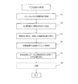
- FIG. 2 is a flowchart showing an outline of the operation of the moving object.
- FIG. 3 is a diagram showing an outline of a control system for controlling the running of each AGV according to the present invention.
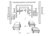
- FIG. 4 is a diagram illustrating an example of the moving space S where the AGV exists.
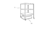
- FIG. 5A is a diagram showing an AGV and a towing cart before being connected.
- FIG. 5B is a diagram showing connected AGVs and tow trucks.
- FIG. 6 is an external view of an exemplary AGV according to the present embodiment.
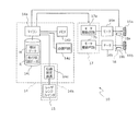
- FIG. 7A is a diagram illustrating a first hardware configuration example of AGV.
- FIG. 7B is a diagram illustrating a second hardware configuration example of AGV.
- FIG. 8A is a diagram illustrating an AGV that generates a map while moving.
- FIG. 8B is a diagram illustrating an AGV that generates a map while moving.
- FIG. 8C is a diagram illustrating an AGV that generates a map while moving.
- FIG. 8D is a diagram illustrating an AGV that generates a map while moving.
- FIG. 8E is a diagram illustrating an AGV that generates a map while moving.
- FIG. 8F is a diagram schematically showing a part of the completed map.
- FIG. 9 is a diagram illustrating an example in which a map of one floor is configured by a plurality of partial maps.
- FIG. 9 is a diagram illustrating an example in which a map of one floor is configured by a plurality of partial maps.
- FIG. 10 is a diagram illustrating a hardware configuration example of the operation management apparatus.
- FIG. 11 is a diagram schematically illustrating an example of the movement route of the AGV determined by the operation management device.
- FIG. 12 is a diagram illustrating a configuration of the AGV 10 according to an exemplary embodiment.
- FIG. 13A is a schematic diagram illustrating an example of an environment image 90 captured by the stereo camera 25 in the space 80 in which the AGV 10 travels.
- FIG. 13B is a schematic diagram illustrating an example in which the environment image 90 is divided into a feature point extraction target region 90A and an image object detection target region 90B.
- FIG. 14 is a diagram for explaining an AGV 10 that travels in a mixed manner of self-position estimation using feature points and self-position estimation using image objects.
- Automated guided vehicle means a trackless vehicle that loads a load on the body manually or automatically, automatically travels to the designated place, and unloads manually or automatically.
- Automated guided vehicle includes automatic guided vehicles and automatic forklifts.
- the term“ unmanned ” means that no person is required to steer the vehicle, and it does not exclude that the automated guided vehicle transports“ person (for example, a person who loads and unloads luggage) ”.
- Unmanned tow truck refers to a trackless vehicle that automatically pulls a cart that loads and unloads packages manually or automatically to a designated location.
- Unmanned forklift is a trackless vehicle equipped with a mast that moves up and down a load transfer fork, etc., automatically transfers the load to the fork, etc., automatically travels to the designated location, and performs automatic load handling work.
- a trackless vehicle is a vehicle that includes wheels and an electric motor or engine that rotates the wheels.
- a “moving body” is a device that carries a person or a load and moves, and includes a driving device such as a wheel, a biped or multi-legged walking device, and a propeller that generate driving force (traction) for movement.
- the term “mobile body” in the present invention includes not only a narrow automatic guided vehicle but also a mobile robot, a service robot, and a drone.
- Autonomous travel includes travel based on a command of an operation management system of a computer to which the automatic guided vehicle is connected by communication, and autonomous travel by a control device included in the automatic guided vehicle. Autonomous traveling includes not only traveling where the automated guided vehicle travels to a destination along a predetermined route, but also traveling following a tracking target. Moreover, the automatic guided vehicle may temporarily perform manual travel based on an instruction from the worker. “Automatic travel” generally includes both “guide type” travel and “guideless type” travel, but in the present invention, it means “guideless type” travel.
- “Guide type” is a method in which a derivative is installed continuously or intermittently and a guided vehicle is guided using the derivative.
- “Guideless type” is a method of guiding without installing a derivative.
- the automatic guided vehicle in the embodiment of the present invention includes a position estimation device that estimates its own position, and can travel in a guideless manner.
- the “position estimation device” is a device that estimates the self-position on the environmental map based on sensor data acquired by an external sensor such as a laser range finder.
- External sensor is a sensor that senses the external state of the moving body.
- Examples of the external sensor include a laser range finder (also referred to as a range sensor), a camera (or an image sensor), a LIDAR (Light Detection and Ranging), a millimeter wave radar, and a magnetic sensor.
- Internal sensor is a sensor that senses the internal state of a moving object.
- Examples of the internal sensor include a rotary encoder (hereinafter sometimes simply referred to as “encoder”), an acceleration sensor, and an angular acceleration sensor (for example, a gyro sensor).
- SAM Simultaneous Localization
- Mapping means that self-location estimation and environmental map creation are performed simultaneously.
- the moving object described in the present invention captures a surrounding space with a stereo camera, and uses a generated image (hereinafter referred to as “environment image”) and a plurality of reference images associated with each position in the space. To estimate the self-position.
- the “reference image” is an image of a space taken in advance.
- the moving body can move autonomously.
- An example of such a moving body is an automatic guided vehicle (for example, FIG. 6 described later).
- the moving body extracts a plurality of feature points from the environment image and collates them with a plurality of reference images. The collation is performed from the viewpoint of which reference image of the plurality of reference images the relationship between the plurality of feature points appears most frequently.
- the moving object further detects an image object included in the environment image.
- the image object is, for example, a sign drawn on the floor surface, and is a straight line, a dotted line, a symbol, a character, and / or a color defined as a lane, a median strip, a package destination, or the like.
- the moving body estimates its own position by using the matching result and the detection result. That is, the moving body can extract the feature point from the environment image and simultaneously estimate the self-position in consideration of the meaning of the image object included in the environment image.
- FIG. 1 is a block diagram showing a schematic configuration of a moving object in an exemplary embodiment of the present invention.
- the moving body 101 includes a stereo camera 103, a position estimation device 105, a storage device 106, a controller 107, and a drive device 109.
- the position estimation device 105 and the controller 107 are separate semiconductor integrated circuit chips.
- the position estimation device 105 and the controller 107 can be a single semiconductor integrated circuit chip.
- the driving device 109 includes a mechanism for moving the moving body 101.
- the drive device 109 may include, for example, at least one drive electric motor (hereinafter simply referred to as “motor”) and a motor control circuit that controls the motor.
- motor a drive electric motor
- motor control circuit that controls the motor.
- the stereo camera 103 repeatedly shoots the surrounding space according to the movement of the moving body 101 and generates an environment image for each shooting.
- the shooting interval is, for example, 100 milliseconds.
- the position estimation device 105 refers to the map stored in the storage device 106.
- the “map” is essentially a planar diagram visualized by reducing and symbolizing the state of the space in which the moving object 101 can move.
- a set of images of a space taken before the operation of the moving object 101 is sometimes referred to as a “map”.
- the reason why such a set of reference images is called a map is that each reference image is associated with each position in the space and includes a feature that can specify each position.
- the moving object 101 detects in which reference image the feature point of the captured environment image exists.
- the position associated with the image determined to have the feature points matched at a predetermined ratio or more is the current position of the moving object 101.
- such a set of reference images is regarded as a category of “map”.
- the position estimation device 105 extracts a plurality of feature points from the environment image output from the stereo camera 103, collates the extraction result with a set of reference images, and estimates the position and orientation of the moving object based on the collation result.
- the position estimation device 105 sequentially outputs information (referred to as “position information” in this specification) indicating the estimated position and orientation of the moving body.
- the controller 107 is, for example, a microcontroller unit (microcomputer) that is a semiconductor integrated circuit.
- the controller 107 controls the driving device 109 while referring to the position information output from the position estimation device 105 to move the moving body 101.
- the position estimation device 105 when the position estimation device 105 collates a plurality of feature points extracted from the environment image with a set of reference images, the position estimation device 105 outputs a reliability indicating the degree to which the two match.
- the controller 107 When the reliability becomes less than a predetermined threshold during traveling and the image object in the environmental image can be detected during traveling, the controller 107 does not use the matching result and does not use the image object of the environmental image. You may estimate a self-position using a detection result. Since the moving body 101 only needs to be able to acquire one environmental image, it can estimate its own position even in an indoor environment where GPS cannot be used. Further, the moving object 101 can maintain the estimation accuracy of the self-position by using the image object even when the number of feature points is small or the feature points greatly change.
- FIG. 2 is a flowchart showing an outline of the operation of the exemplary mobile object 101 of the present invention.
- the process according to the flowchart shows the procedure of the process originally executed by a certain CPU, MPU, or microcontroller.
- the flowchart of FIG. 2 shows the processing of the position estimation apparatus 105 and the controller 107 mixed for convenience of understanding.
- the position estimation device 105 and the controller 107 execute each process while exchanging data with each other.
- Steps S1 to S5 are processing of the position estimation device 105.
- Step S ⁇ b> 6 is a process of the controller 107.
- step S1 the position estimation apparatus 105 receives an environment image generated every time the stereo camera 103 repeatedly shoots the surrounding space.
- the position estimation apparatus 105 extracts a plurality of feature points from the environment image in step S2.
- the feature point is, for example, an edge in the image. Since the stereo camera 103 can also acquire depth information based on compound eye parallax information, if the depth differs before and after the edge or right and left, the edge can be determined to be a boundary line of an object existing in the space.
- step S3 the position estimation apparatus 105 collates the plurality of feature points with each of the plurality of reference images. For example, the position estimation apparatus 105 collates to which reference image of the plurality of reference images the relationship that the extracted feature points have most frequently appears. The position estimation apparatus 105 outputs the degree of coincidence as “coincidence”. In addition, since it takes time to process a plurality of feature points and all the reference images every time, the range to be verified may be limited to a part of the reference images.
- step S4 the position estimation device 105 detects an image object from the environment image. Examples of image objects are as described above.
- step S5 the position estimation device 105 estimates the self-position using the collation result in step S3 and / or the detection result in step S4, and outputs position information.
- step S6 the controller 107 starts the position information output from the position estimation device 105 and drives the driving device 109 toward the designated destination to move the moving body 101.
- step S6 is included for convenience of understanding and is not essential for the position identification process itself. Therefore, in FIG. 2, step S6 is indicated by a broken line.
- the mobile unit 101 may have a communication circuit, and obtain the latest reference image from the outside via this communication circuit.
- the communication circuit receives the updated reference image from an external device, for example, an operation management device described later.
- the moving body according to the present invention is an automatic guided vehicle
- the automatic guided vehicle may be described as “AGV” using an abbreviation.
- AGV automatic guided vehicle
- FIG. 3 shows a basic configuration example of an exemplary mobile management system 100 according to the present invention.
- the mobile management system 100 includes at least one AGV 10 and an operation management device 50 that manages the operation of the AGV 10.
- FIG. 3 also shows a terminal device 20 operated by the user 1.
- AGV10 is an automatic guided vehicle that can perform “guideless” traveling that does not require a magnetic tape or other derivative for traveling.
- the AGV 10 can perform self-position estimation and transmit the estimation result to the terminal device 20 and the operation management device 50.
- the AGV 10 can automatically travel in the moving space S in accordance with a command from the operation management device 50.
- the AGV 10 is further capable of operating in a “tracking mode” in which it moves following a person or other moving body.
- the operation management device 50 is a computer system that tracks the position of each AGV 10 and manages the running of each AGV 10.
- the operation management device 50 may be a desktop PC, a notebook PC, and / or a server computer.
- the operation management device 50 communicates with each AGV 10 via the plurality of access points 2. For example, the operation management apparatus 50 transmits the data of the coordinates of the position where each AGV 10 should go next to each AGV 10.
- Each AGV 10 transmits data indicating its own position and orientation to the operation management device 50 periodically, for example, every 100 milliseconds.
- the operation management device 50 transmits data on the coordinates of the position to be further headed.
- the AGV 10 can travel in the moving space S according to the operation of the user 1 input to the terminal device 20.
- An example of the terminal device 20 is a tablet computer.
- the travel of the AGV 10 using the terminal device 20 is performed at the time of map creation, and the travel of the AGV 10 using the operation management device 50 is performed after the map creation.
- FIG. 4 shows an example of a moving space S in which three AGVs 10a, 10b, and 10c exist. Assume that all AGVs are traveling in the depth direction in the figure. The AGVs 10a and 10b are transporting loads placed on the top board. The AGV 10c travels following the front AGV 10b.
- reference numerals 10a, 10b, and 10c are assigned in FIG. 4, but are hereinafter referred to as “AGV10”.
- the AGV 10 can also transport packages using a tow truck connected to itself, in addition to a method of transporting packages placed on the top board.
- FIG. 5A shows the AGV 10 and the traction cart 5 before being connected. A caster is provided on each foot of the traction cart 5. The AGV 10 is mechanically connected to the traction cart 5.
- FIG. 5B shows the AGV 10 and the traction cart 5 connected. When the AGV 10 travels, the tow cart 5 is pulled by the AGV 10. By pulling the tow cart 5, the AGV 10 can transport the load placed on the tow cart 5.
- connection method between the AGV 10 and the towing cart 5 is arbitrary.
- a plate 6 is fixed to the top plate of the AGV 10.
- the pulling cart 5 is provided with a guide 7 having a slit.
- the AGV 10 approaches the tow truck 5 and inserts the plate 6 into the slit of the guide 7.
- the AGV 10 passes an electromagnetic lock pin (not shown) through the plate 6 and the guide 7 and applies an electromagnetic lock. Thereby, AGV10 and tow cart 5 are physically connected.
- Each AGV 10 and the terminal device 20 can be connected, for example, on a one-to-one basis, and can perform communication based on the Bluetooth (registered trademark) standard.
- Each AGV 10 and the terminal device 20 can perform communication based on Wi-Fi (registered trademark) using one or a plurality of access points 2.
- the plurality of access points 2 are connected to each other via, for example, the switching hub 3.
- FIG. 3 shows two access points 2a and 2b.
- the AGV 10 is wirelessly connected to the access point 2a.
- the terminal device 20 is wirelessly connected to the access point 2b.
- the data transmitted by the AGV 10 is received by the access point 2a, transferred to the access point 2b via the switching hub 3, and transmitted from the access point 2b to the terminal device 20.
- the data transmitted by the terminal device 20 is received by the access point 2b, transferred to the access point 2a via the switching hub 3, and transmitted from the access point 2a to the AGV 10. Thereby, bidirectional communication between the AGV 10 and the terminal device 20 is realized.
- the plurality of access points 2 are also connected to the operation management device 50 via the switching hub 3. Thereby, bidirectional communication is also realized between the operation management device 50 and each AGV 10.
- a map in the moving space S is created so that the AGV 10 can travel while estimating its own position.
- the AGV 10 is equipped with a position estimation device and a laser range finder, and a map can be created using the output of the laser range finder.
- the AGV10 shifts to a data acquisition mode by a user operation.
- the AGV 10 starts acquiring sensor data using the laser range finder.
- the laser range finder periodically scans the surrounding moving space S by periodically emitting, for example, an infrared or visible laser beam.
- the laser beam is reflected by the surface of a structure such as a wall or a pillar or an object placed on the floor.
- the laser range finder receives the reflected light of the laser beam, calculates the distance to each reflection point, and outputs measurement result data indicating the position of each reflection point.
- the direction and distance of the reflected light are reflected at the position of each reflection point.
- the measurement result data may be referred to as “measurement data” or “sensor data”.
- the position estimation device accumulates sensor data in a storage device.
- the sensor data accumulated in the storage device is transmitted to the external device.
- the external device is, for example, a computer having a signal processor and having a mapping program installed therein.
- the signal processor of the external device superimposes the sensor data obtained for each scan.
- a map of the moving space S can be created by repeatedly performing the process of overlapping by the signal processor.
- the external device transmits the created map data to the AGV 10.
- the AGV 10 stores the created map data in an internal storage device.
- the external device may be the operation management device 50 or another device.
- the AGV 10 may create the map instead of the external device.
- the processing performed by the signal processor of the external device described above may be performed by a circuit such as a microcontroller unit (microcomputer) of the AGV 10.
- a map is created in the AGV 10
- the data capacity of sensor data is generally considered large. Since it is not necessary to transmit sensor data to an external device, occupation of the communication line can be avoided.
- the movement in the movement space S for acquiring sensor data can be realized by the AGV 10 traveling according to the user's operation.
- the AGV 10 receives a travel command instructing movement in the front, rear, left, and right directions from the user via the terminal device 20 wirelessly.
- the AGV 10 travels forward and backward, left and right in the movement space S according to the travel command, and creates a map.
- the AGV 10 may travel in the moving space S in the front / rear and left / right directions according to a control signal from the steering device to create a map.
- Sensor data may be acquired by a person walking around a measurement carriage equipped with a laser range finder.
- FIG 3 and 4 show a plurality of AGVs 10, one AGV may be used.
- the user 1 selects one AGV 10 from the plurality of registered AGVs using the terminal device 20, and creates a map of the moving space S in the selected AGV 10. Can be made.
- each AGV 10 can automatically travel while estimating its own position using the map. A description of the process of estimating the self position will be given later.
- FIG. 6 is an external view of an exemplary AGV 10.
- the AGV 10 includes two drive wheels 11a and 11b, four casters 11c, 11d, 11e, and 11f, a frame 12, a transport table 13, a travel control device 14, and a laser range finder 15.
- the two drive wheels 11a and 11b are provided on the right side and the left side of the AGV 10, respectively.
- the four casters 11c, 11d, 11e, and 11f are arranged at the four corners of the AGV 10.
- the AGV 10 also has a plurality of motors connected to the two drive wheels 11a and 11b, but the plurality of motors are not shown in FIG. FIG.
- FIG. 6 shows one drive wheel 11a and two casters 11c and 11e located on the right side of the AGV 10, and a caster 11f located on the left rear part.
- the caster 11d is not clearly shown because it is hidden behind the frame 12.
- the four casters 11c, 11d, 11e, and 11f can freely turn.
- the drive wheels 11a and the drive wheels 11b are also referred to as wheels 11a and wheels 11b, respectively.
- the AGV 10 further includes at least one obstacle sensor 19 for detecting an obstacle.
- the obstacle sensor 19 may be a device capable of measuring a distance, such as an infrared sensor, an ultrasonic sensor, or a stereo camera.
- the obstacle sensor 19 is an infrared sensor, for example, an obstacle that exists within a certain distance is detected by emitting an infrared ray every fixed time and measuring the time until the reflected infrared ray returns. Can do.
- the AGV 10 detects an obstacle on the path based on the signal output from the at least one obstacle sensor 19, the AGV 10 performs an operation to avoid the obstacle.
- the operation of avoiding the obstacle is, for example, an operation of moving while avoiding the obstacle.
- the traveling control device 14 is a device that controls the operation of the AGV 10, and mainly includes an integrated circuit including a microcomputer (described later), electronic components, and a board on which they are mounted.
- the traveling control device 14 performs the above-described data transmission / reception with the terminal device 20 and the preprocessing calculation.
- the laser range finder 15 is an optical instrument that measures the distance to the reflection point by, for example, emitting an infrared or visible laser beam 15a and detecting the reflected light of the laser beam 15a.
- the laser range finder 15 of the AGV 10 radiates a pulsed laser beam 15a while changing the direction every 0.25 degrees, for example, in a space of 135 degrees left and right (total 270 degrees) with respect to the front of the AGV 10, The reflected light of each laser beam 15a is detected. Thereby, data of the distance to the reflection point in the direction determined by the angle corresponding to the total of 1081 steps every 0.25 degrees can be obtained.
- the scanning of the surrounding space performed by the laser range finder 15 is substantially parallel to the floor surface and is planar (two-dimensional). However, the laser range finder 15 may perform scanning in the height direction.
- the AGV 10 can create a map of the moving space S based on the position and orientation (orientation) of the AGV 10 and the scan result of the laser range finder 15.
- the map may reflect the arrangement of walls, pillars and other structures around the AGV, and objects placed on the floor.
- the map data is stored in a storage device provided in the AGV 10.
- the position and posture of the moving body are called poses.
- the position and orientation of the moving body in the two-dimensional plane are expressed by position coordinates (x, y) in the XY orthogonal coordinate system and an angle ⁇ with respect to the X axis.
- the position and posture of the AGV 10, that is, the pose (x, y, ⁇ ) may be simply referred to as “position” hereinafter.
- the position of the reflection point viewed from the radiation position of the laser beam 15a can be expressed using polar coordinates determined by the angle and the distance.
- the laser range finder 15 outputs sensor data expressed in polar coordinates. However, the laser range finder 15 may convert the position expressed in polar coordinates into orthogonal coordinates and output the result.
- Examples of objects that can be detected by the laser range finder 15 are people, luggage, shelves, and walls.
- the laser range finder 15 is an example of an external sensor for sensing the surrounding space and acquiring sensor data.
- Other examples of such an external sensor include an image sensor and an ultrasonic sensor.
- the traveling control device 14 can estimate the current position of the AGV 10 by comparing the measurement result of the laser range finder 15 with the map data held by itself.
- the stored map data may be map data created by another AGV 10.
- FIG. 7A shows a first hardware configuration example of the AGV 10.
- FIG. 7A also shows a specific configuration of the travel control device 14.
- the AGV 10 includes a travel control device 14, a laser range finder 15, two motors 16a and 16b, a drive device 17, wheels 11a and 11b, and two rotary encoders 18a and 18b.
- the traveling control device 14 includes a microcomputer 14a, a memory 14b, a storage device 14c, a communication circuit 14d, and a position estimation device 14e.
- the microcomputer 14a, the memory 14b, the storage device 14c, the communication circuit 14d, and the position estimation device 14e are connected by a communication bus 14f and can exchange data with each other.
- the laser range finder 15 is also connected to the communication bus 14f via a communication interface (not shown), and transmits measurement data as a measurement result to the microcomputer 14a, the position estimation device 14e, and / or the memory 14b.
- the microcomputer 14a is a processor or a control circuit (computer) that performs calculations for controlling the entire AGV 10 including the travel control device 14.
- the microcomputer 14a is a semiconductor integrated circuit.
- the microcomputer 14a transmits a PWM (Pulse Width Modulation) signal, which is a control signal, to the drive device 17 to control the drive device 17 and adjust the voltages applied to the motors 16a and 16b. As a result, each of the motors 16a and 16b rotates at a desired rotation speed.
- PWM Pulse Width Modulation
- One or more control circuits for example, a microcomputer for controlling the driving of the left and right motors 16a and 16b may be provided independently of the microcomputer 14a.
- the driving device 17 may include two microcomputers that control driving of the motors 16a and 16b, respectively. These two microcomputers may perform coordinate calculations using the encoder information output from the rotary encoders 18a and 18b, respectively, and estimate the moving distance of the AGV 10 from a predetermined initial position.
- the two microcomputers may control the motor drive circuits 17a and 17b using encoder information.
- the memory 14b is a volatile storage device that stores a computer program executed by the microcomputer 14a.
- the memory 14b can also be used as a work memory when the microcomputer 14a and the position estimation device 14e perform calculations.
- the storage device 14c is a non-volatile semiconductor memory device.
- the storage device 14c may be a magnetic recording medium typified by a hard disk or an optical recording medium typified by an optical disk.
- the storage device 14c may include a head device for writing and / or reading data on any recording medium and a control device for the head device.
- the storage device 14c stores map data M of the traveling space S in which the vehicle travels, and data (travel route data) R of one or more travel routes.
- the map data M is created by the AGV 10 operating in the map creation mode and stored in the storage device 14c.
- the travel route data R is transmitted from the outside after the map data M is created.
- the map data M and the travel route data R are stored in the same storage device 14c, but may be stored in different storage devices.
- the AGV 10 receives travel route data R indicating a travel route from the tablet computer.
- the travel route data R at this time includes marker data indicating the positions of a plurality of markers. “Marker” indicates the passing position (via point) of the traveling AGV 10.
- the travel route data R includes at least position information of a start marker indicating a travel start position and an end marker indicating a travel end position.
- the travel route data R may further include position information of one or more intermediate waypoint markers. When the travel route includes one or more intermediate waypoints, a route from the start marker to the end marker via the travel route point in order is defined as the travel route.
- the data of each marker may include data on the direction (angle) and traveling speed of the AGV 10 until moving to the next marker, in addition to the coordinate data of the marker.
- the data of each marker includes acceleration time required for acceleration to reach the travel speed, and / or Further, it may include data of deceleration time required for deceleration from the traveling speed until the vehicle stops at the position of the next marker.
- the operation management device 50 (for example, a PC and / or a server computer) instead of the terminal device 20 may control the movement of the AGV 10. In that case, the operation management device 50 may instruct the AGV 10 to move to the next marker every time the AGV 10 reaches the marker. For example, the AGV 10 receives, from the operation management device 50, the coordinate data of the target position to be next, or the data of the distance to the target position and the angle to travel as the travel route data R indicating the travel route.
- the AGV 10 can travel along the stored travel route while estimating its own position using the created map and the sensor data output from the laser range finder 15 acquired during travel.
- the communication circuit 14d is a wireless communication circuit that performs wireless communication based on, for example, Bluetooth (registered trademark) and / or Wi-Fi (registered trademark) standards. Each standard includes a wireless communication standard using a frequency of 2.4 GHz band. For example, in a mode in which the AGV 10 is run to create a map, the communication circuit 14d performs wireless communication based on the Bluetooth (registered trademark) standard and communicates with the terminal device 20 one-on-one.
- Bluetooth registered trademark
- Wi-Fi registered trademark
- the position estimation device 14e performs map creation processing and self-position estimation processing when traveling.
- the position estimation device 14e creates a map of the moving space S based on the position and orientation of the AGV 10 and the scan result of the laser range finder 15.
- the position estimation device 14e receives sensor data from the laser range finder 15 and reads map data M stored in the storage device 14c.
- the position estimation device 14e performs matching between the local map data (sensor data) created from the scan result of the laser range finder 15 and the map data M in a wider range, so that the self-position (x , y, ⁇ ).
- the position estimation device 14e generates “reliability” data representing the degree to which the local map data matches the map data M.
- Each data of the self position (x, y, ⁇ ) and the reliability can be transmitted from the AGV 10 to the terminal device 20 or the operation management device 50.
- the terminal device 20 or the operation management device 50 can receive each data of its own position (x, y, ⁇ ) and reliability and display it on a built-in or connected display device.
- the microcomputer 14a and the position estimation device 14e are separate components, but this is an example.
- the microcomputer 14a and the position estimation device 14e may be a single chip circuit or a semiconductor integrated circuit that can independently perform the operations of the microcomputer 14a and the position estimation device 14e.
- FIG. 7A shows a chip circuit 14g including the microcomputer 14a and the position estimation device 14e. Below, the example in which the microcomputer 14a and the position estimation apparatus 14e are provided independently is demonstrated.
- the two motors 16a and 16b are attached to the two wheels 11a and 11b, respectively, and rotate the wheels 11a and 11b. That is, the two wheels 11a and 11b are drive wheels, respectively.
- the motor 16a and the motor 16b are described as being motors for driving the right wheel (wheel 11a) and the left wheel (wheel 11b) of the AGV 10, respectively.
- the moving body 10 further includes an encoder unit 18 that measures the rotational positions or rotational speeds of the wheels 11a and 11b.
- the encoder unit 18 includes a rotary encoder 18a and a rotary encoder 18b.
- the rotary encoder 18a measures the rotation at any position of the power transmission mechanism from the motor 16a to the wheel 11a.
- the rotary encoder 18b measures the rotation at any position of the power transmission mechanism from the motor 16b to the wheel 11b.
- the encoder unit 18 transmits the signals acquired by the rotary encoders 18a and 18b to the microcomputer 14a.
- the microcomputer 14a may control the movement of the moving body 10 using the signal received from the encoder unit 18 as well as the signal received from the position estimation device 14e.
- the drive device 17 has motor drive circuits 17a and 17b for adjusting the voltage applied to each of the two motors 16a and 16b.
- Each of motor drive circuits 17a and 17b includes a so-called inverter circuit.
- the motor drive circuit 17a turns on or off the current flowing through the motor 16a by the PWM signal transmitted from the microcomputer 14a or the microcomputer in the motor drive circuit 17a, thereby adjusting the voltage applied to the motor 16a.
- the motor drive circuit 17b turns on or off the current flowing through the motor 16b by the PWM signal transmitted from the microcomputer 14a or the microcomputer in the motor drive circuit 17b, thereby adjusting the voltage applied to the motor 16b.
- FIG. 7B shows a second hardware configuration example of the AGV 10.
- the second hardware configuration example is different from the first hardware configuration example (FIG. 7A) in that it has a laser positioning system 14h and that the microcomputer 14a is connected to each component in a one-to-one relationship. To do.
- the laser positioning system 14 h includes a position estimation device 14 e and a laser range finder 15.
- the position estimation device 14e and the laser range finder 15 are connected by, for example, an Ethernet (registered trademark) cable. Each operation of the position estimation device 14e and the laser range finder 15 is as described above.
- the laser positioning system 14h outputs information indicating the pause (x, y, ⁇ ) of the AGV 10 to the microcomputer 14a.
- the microcomputer 14a has various general purpose I / O interfaces or general purpose input / output ports (not shown).
- the microcomputer 14a is directly connected to other components in the travel control device 14 such as the communication circuit 14d and the laser positioning system 14h via the general-purpose input / output port.
- the AGV 10 may include a safety sensor such as a bumper switch (not shown).
- the AGV 10 may include an inertial measurement device such as a gyro sensor.
- the AGV 10 can estimate the movement distance and the change amount (angle) of the AGV 10 by using measurement data obtained by an internal sensor such as the rotary encoders 18a and 18b or an inertial measurement device. These estimated values of distance and angle are called odometry data, and can exhibit a function of assisting position and orientation information obtained by the position estimation device 14e.
- FIGS. 8A, 8B, 8C, 8D, 8E, and 8F are diagrams schematically illustrating the AGV 10 that moves while acquiring sensor data.
- the user 1 may move the AGV 10 manually while operating the terminal device 20.
- the sensor data may be acquired by placing the unit including the traveling control device 14 shown in FIGS. 7A and 7B, or the AGV 10 itself on the carriage, and the user 1 pushing or checking the carriage by hand. .
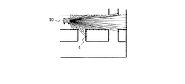
- FIG. 8A shows an AGV 10 that scans the surrounding space using the laser range finder 15.
- a laser beam is emitted at every predetermined step angle, and scanning is performed.
- the illustrated scan range is an example schematically shown, and is different from the above-described scan range of 270 degrees in total.
- the position of the reflection point of the laser beam is schematically shown using a plurality of black spots 4 represented by the symbol “ ⁇ ”.
- the laser beam scan is executed in a short cycle while the position and posture of the laser range finder 15 change. For this reason, the actual number of reflection points is much larger than the number of black spots 4 shown in the figure.
- the position estimation device 14e accumulates the position of the black spot 4 obtained as the vehicle travels, for example, in the memory 14b.
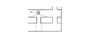
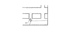
- the map data is gradually completed by continuously performing scanning while the AGV 10 is traveling. 8B to 8E, only the scan range is shown for the sake of simplicity.
- the scan range is an example, and is different from the above-described example of 270 degrees in total.
- the map may be created using the microcomputer 14a in the AGV 10 or an external computer on the basis of the sensor data after acquiring the amount of sensor data necessary for creating the map.
- the map may be created in real time based on sensor data acquired by the moving AGV 10.
- FIG. 8F is a diagram schematically showing a part of the completed map 40.
- the free space is partitioned by a point cloud (Point Cloud) corresponding to a collection of laser beam reflection points.
- Point Cloud Point Cloud
- Another example of the map is an occupied grid map that distinguishes between a space occupied by an object and a free space in units of grids.
- the position estimation device 14e accumulates map data (map data M) in the memory 14b or the storage device 14c.
- map data M map data M
- the number or density of black spots shown in the figure is an example.
- the map data obtained in this way can be shared by a plurality of AGVs 10.
- a typical example of an algorithm in which the AGV 10 estimates its own position based on map data is ICP (Iterative Closest Point) matching.
- ICP Intelligent Closest Point
- the AGV 10 matches the local map data (sensor data) created from the scan result of the laser range finder 15 with a wider range of map data M, so that the map data M is displayed on the map data M.
- the self position (x, y, ⁇ ) can be estimated.
- the map data M may be created and recorded separately for a plurality of partial map data.
- FIG. 9 shows an example in which the entire area of one floor of one factory is covered by a combination of four partial map data M1, M2, M3, and M4.
- one partial map data covers an area of 50 m ⁇ 50 m.
- a rectangular overlapping region having a width of 5 m is provided at the boundary between two adjacent maps in each of the X direction and the Y direction. This overlapping area is called a “map switching area”.
- the AGV 10 travels while referring to one partial map. When the AGV 10 reaches the map switching area, the AGV 10 switches to travel referring to another adjacent partial map.
- the number of partial maps is not limited to four, and may be set as appropriate according to the area of the floor on which the AGV 10 travels, the performance of the computer that executes map creation and self-position estimation.
- the size of the partial map data and the width of the overlapping area are not limited to the above example, and may be arbitrarily set.
- FIG. 10 shows a hardware configuration example of the operation management device 50.
- the operation management device 50 includes a CPU 51, a memory 52, a position database (position DB) 53, a communication circuit 54, a map database (map DB) 55, and an image processing circuit 56.
- the CPU 51, the memory 52, the position DB 53, the communication circuit 54, the map DB 55, and the image processing circuit 56 are connected by a bus 57 and can exchange data with each other.
- the CPU 51 is a signal processing circuit (computer) that controls the operation of the operation management device 50.
- the CPU 51 is a semiconductor integrated circuit.
- the memory 52 is a volatile storage device that stores a computer program executed by the CPU 51.
- the memory 52 can also be used as a work memory when the CPU 51 performs calculations.
- the position DB 53 stores position data indicating each position that can be a destination of each AGV 10.
- the position data can be represented by coordinates virtually set in the factory by an administrator, for example.
- the location data is determined by the administrator.
- the communication circuit 54 performs wired communication conforming to, for example, the Ethernet (registered trademark) standard.
- the communication circuit 54 is connected to the access point 2 (FIG. 3) by wire, and can communicate with the AGV 10 via the access point 2.
- the communication circuit 54 receives data to be transmitted to the AGV 10 from the CPU 51 via the bus 57.
- the communication circuit 54 transmits the data (notification) received from the AGV 10 to the CPU 51 and / or the memory 52 via the bus 57.
- the map DB 55 stores map data inside the factory where the AGV 10 is traveling.
- the map may be the same as or different from the map 40 (FIG. 8F).
- the map stored in the map DB 55 has a one-to-one correspondence with the position of each AGV 10, the data format is not limited.
- the map stored in the map DB 55 may be a map created by CAD.
- the position DB 53 and the map DB 55 may be constructed on a nonvolatile semiconductor memory, or may be constructed on a magnetic recording medium represented by a hard disk or an optical recording medium represented by an optical disk.
- the image processing circuit 56 is a circuit that generates video data to be displayed on the monitor 58.
- the image processing circuit 56 operates exclusively when the administrator operates the operation management device 50.
- the monitor 59 may be integrated with the operation management device 50. Further, the CPU 51 may perform the processing of the image processing circuit 56.
- FIG. 11 is a diagram schematically illustrating an example of the movement route of the AGV 10 determined by the operation management device 50.
- the outline of the operation of the AGV 10 and the operation management device 50 is as follows. In the following, an example will be described in which a certain AGV 10 is currently at the position M1, passes through several positions, and travels to the final destination position Mn + 1 (n: a positive integer of 1 or more).
- position DB 53 coordinate data indicating positions such as a position M2 to be passed next to the position M1, a position M3 to be passed next to the position M2, and the like are recorded.
- the CPU 51 of the operation management device 50 reads out the coordinate data of the position M2 with reference to the position DB 53, and generates a travel command for moving to the position M2.
- the communication circuit 54 transmits a travel command to the AGV 10 via the access point 2.
- the CPU 51 periodically receives data indicating the current position and posture from the AGV 10 via the access point 2.
- the operation management device 50 can track the position of each AGV 10.
- the CPU 51 determines that the current position of the AGV 10 coincides with the position M2
- the CPU 51 reads the coordinate data of the position M3, generates a traveling command to be directed to the position M3, and transmits it to the AGV 10.
- the operation management apparatus 50 transmits a travel command for directing to the position to be passed next.
- the AGV 10 can reach the final target position Mn + 1.
- the above-described passing position and target position of the AGV 10 may be referred to as “markers”.
- FIG. 12 shows the configuration of the AGV 10 according to the present embodiment.
- the stereo camera 25 is a camera that can record not only images but also information in the depth direction by simultaneously photographing an object from a plurality of different directions.
- the stereo camera 25 is two digital cameras arranged side by side at a distance of several centimeters to several tens of centimeters in the horizontal direction.
- the two digital cameras correspond to the right eye and the left eye of the stereo camera 25, and each has a lens and an image sensor that receives light incident on the lens.
- Each image sensor may be a CMOS image sensor or a CCD image that outputs an image signal.
- the stereo camera 25 includes an arithmetic circuit that calculates the parallax of the images of the left and right digital cameras taken in synchronization and calculates the distance to the subject corresponding to the parallax. Since the method for calculating the parallax is known, a specific description thereof will be omitted in this specification.
- FIG. 7B can also be adopted as the AGV 10 according to the present embodiment if the laser range finder 15 is changed to the stereo camera 25. Illustration of the AGV 10 having the stereo camera 25 corresponding to the configuration of FIG. 7B is omitted.
- AGV10 concerning this embodiment may have a stereo camera and a laser range finder. That is, this embodiment does not exclude the use of a laser range finder.
- the difference between the AGV 10 of FIG. 12 and the AGV 10 of FIG. 7A regarding the data is the substance of the map data M.
- the storage device 14c in FIG. 12 stores a plurality of reference images associated with each position in the space.
- Each reference image is an image obtained by photographing the space 80 (see FIG. 13A) in advance. Since the position at the time of shooting the reference image is known in advance, position information in the space 80 of each reference image can be associated with each reference image.
- FIG. 13A schematically shows an example of an environment image 90 taken by the stereo camera 25 in the space 80 where the AGV 10 travels.
- the environment image 90 illustrated is, for example, an image of the left eye of the stereo camera 25, and description of the right eye image is omitted.
- a broken-line rectangle in the drawing represents the range of the environment image 90, in other words, the visual field of the left eye of the stereo camera 25.
- FIG. 13A it is understood that there is a cabinet 82 and a desk 84 that is elongated in the depth direction.
- the position estimation device 14e of the AGV 10 receives the environment image 90 from the stereo camera 25 and analyzes the environment image 90.
- “Analysis” here is extraction of feature points and detection of image objects.
- the position estimation device 14e of the AGV 10 has an “image processing rule” in advance.
- the “image processing rule” includes a rule for extracting feature points and a rule for detecting image objects.
- the rule for extracting feature points is a rule for identifying both pixels in the environmental image 90 whose luminance difference between adjacent pixels is equal to or greater than a threshold value as feature points. More simply, the rule for extracting a feature point is a rule for making a pixel group constituting an “edge” in the environment image 90 a feature point.
- the feature points may be determined by other methods as long as the method is defined as a rule for extracting feature points.
- the rule for detecting an image object is a rule for identifying two parallel white lines as an image object.
- the system administrator means that two parallel white lines are marks on the traveling lane of the AGV 10 drawn on the floor surface of the space 80. Is given.
- a rule for detecting an image object a rule that a white dotted line between two parallel white lines is a median strip and a yellow straight line is a place where a load is placed is provided. You can also.
- the position estimation device 14e detects the pixel group as an image object when there is a pixel group that matches the rule for detecting the image object in the environment image 90.
- FIG. 13A shows a large number of extracted feature points represented by “ ⁇ ” (for example, reference numeral 91) and two parallel white line image objects 92A and 92B as analysis results.
- FIG. 13B schematically illustrates an example in which the environment image 90 is divided into a feature point extraction target region 90A and an image object detection target region 90B.
- the processing load can be reduced by limiting the region in which the environment image 90 is analyzed.
- “ ⁇ ” indicating a feature point is extracted in the area 90A, and the image objects 92A and 92B are detected in the area 90B.
- the region 90B is located below the region 90A. This is because the rule for detecting an image object assumes that a sign drawn on the floor is detected as an image object. Therefore, the positional relationship between the regions 90A and 90B can be determined according to the “image processing rule” described above. Further, the regions 90A and 90B may not be one and the other of the environment image 90 divided into two, or a plurality of regions 90A and / or 90B may be provided.
- the position estimation device 14e of the AGV 10 collates the extracted feature points with each of the plurality of reference images stored as the map data M in the storage device 14c. This will be described more specifically.
- the plurality of reference images are captured in advance and stored in the storage device 14c.
- the position estimation device 14e applies the above-described rule for extracting feature points to each reference image, and extracts the feature points in each reference image in advance.
- the position estimation apparatus 14e can collate the extracted feature points.
- the position estimation device 14e determines whether the positional relationship between the plurality of feature points in the environment image 90 has a large correlation with the positional relationship between the plurality of feature points in which reference image. As a result, the position estimation device 14e determines a reference image having a feature point having the largest correlation with the extracted feature point.
- the method for calculating the correlation is arbitrary.
- the magnitude of the correlation can be quantitatively evaluated by obtaining the magnitude of the correlation coefficient.
- the correlation coefficient between the feature point of the environment image 90 and the feature point of a certain reference image is obtained by dividing the covariance by the standard deviation of the feature point of the environment image 90 and by the standard deviation of the feature point of the reference image. It is required by doing.
- data representing feature points may be stored in the storage device 14c together with each reference image or instead of each reference image. This eliminates the need for the position estimation device 14e to extract the feature points of each reference image each time.
- the position estimation device 14e estimates that the position associated with the determined reference image is the current position of the AGV 10.
- the position estimation device 14e can estimate the self position from the meaning of the detected image object.
- data in which an image object is associated with a position in the space 80 is prepared in advance.
- the appearance and the position according to the appearance can be associated with each other.
- the position estimation device 14e can determine the position of the detected image object also by using the image object and the data.
- FIG. 14 is a diagram for explaining the AGV 10 that travels in a mixed manner of self-position estimation using feature points and self-position estimation using image objects.
- the AGV 10 is traveling in the right direction of the drawing.
- the position estimation device 14e of the AGV 10 may perform self-position estimation based on the image object, interpolate self-position estimation based on the feature points, and improve the position estimation accuracy.
- the processing of the position estimation device 14e at this time is represented by the flowchart shown in FIG. Therefore, the re-explanation is omitted.
- the reliability that is the degree of coincidence between the feature points of the environment image and the feature points of the reference image is set as a threshold because the walls 112 on both sides of the position P are monotonous. In some cases, the accuracy of self-position estimation decreases.
- a position can be known in advance. Therefore, for example, two white lines 114 are prepared at such positions, and a plurality of marks are given to the two white lines 114 according to the positions. The AGV 10 can detect each mark as the two white lines 114 are detected. If the data which linked
- the processing of the position estimation device 14e at this time means that steps S4 and S5 are executed as a result in the flowchart shown in FIG.
- the AGV 10 holds a set of reference images in advance, and estimates the current position by comparing the feature points of the image acquired by the stereo camera 25 with the feature points of each reference image.
- the present invention can be operated while the AGV 10 estimates its own position without preparing such a reference image in advance.
- the AGV 10 can calculate the relative movement amount of the AGV 10 from the previous shooting to the current shooting from the change in parallax. As long as the absolute coordinates for starting the movement are correctly given, the AGV 10 can move while accumulating the relative movement amount and grasping the current position. According to the above method, the present invention does not need to prepare a reference image in advance.
- the AGV 10 can be run according to the meaning.
- the image object is yellow, has a width of Xcm, and has a length of Ycm or more, it means that the image object is an area where a load is placed.
- the AGV 10 does not cross even if it stops near the area for unloading the load. Therefore, when the traveling AGV 10 detects an image object that meets the above-described conditions, the AGV 10 can travel so as not to cross a line corresponding to the image object during traveling.
- the comprehensive or specific aspect described above may be realized by a system, a method, an integrated circuit, a computer program, or a recording medium.
- the present invention may be realized by any combination of a system, an apparatus, a method, an integrated circuit, a computer program, and a recording medium.
- the exemplary mobile body and mobile system of the present invention can be suitably used for moving and transporting goods such as luggage, parts, and finished products in factories, warehouses, construction sites, logistics, hospitals, and the like.
Landscapes
- Engineering & Computer Science (AREA)
- Aviation & Aerospace Engineering (AREA)
- Radar, Positioning & Navigation (AREA)
- Remote Sensing (AREA)
- Physics & Mathematics (AREA)
- General Physics & Mathematics (AREA)
- Automation & Control Theory (AREA)
- Control Of Position, Course, Altitude, Or Attitude Of Moving Bodies (AREA)
Abstract
Un objectif de la présente invention est de fournir une technologie avec laquelle un corps mobile estime son emplacement actuel. L'invention concerne un corps mobile (101) capable de réaliser un mouvement autonome, ledit corps mobile (101) comprenant : un dispositif d'entraînement (109) pour déplacer le corps mobile ; une caméra stéréo (103) pour photographier de manière répétée un espace dans le voisinage tout en étant en mouvement et générer une image d'environnement pour chaque instance de photographie ; un dispositif de stockage (106) pour stocker une pluralité d'images de référence, dont chacune est associée à chaque position respective dans l'espace ; un dispositif de localisation (105) pour délivrer séquentiellement des informations de position de l'emplacement actuel, à l'aide des images d'environnement et de la pluralité d'images de référence ; et un dispositif de commande (107) pour commander le dispositif d'entraînement et amener le corps mobile à se déplacer tout en se référant aux informations de position délivrées par le dispositif de localisation. Le dispositif de localisation extrait une pluralité de points caractéristiques à partir des images d'environnement, les compare à la pluralité d'images de référence, détecte un objet d'image contenu dans les images d'environnement et estime l'emplacement actuel à l'aide du résultat de comparaison et du résultat de détection.
Priority Applications (1)
| Application Number | Priority Date | Filing Date | Title |
|---|---|---|---|
| JP2020510427A JPWO2019187816A1 (ja) | 2018-03-30 | 2019-02-20 | 移動体および移動体システム |
Applications Claiming Priority (2)
| Application Number | Priority Date | Filing Date | Title |
|---|---|---|---|
| JP2018068382 | 2018-03-30 | ||
| JP2018-068382 | 2018-03-30 |
Publications (1)
| Publication Number | Publication Date |
|---|---|
| WO2019187816A1 true WO2019187816A1 (fr) | 2019-10-03 |
Family
ID=68059823
Family Applications (1)
| Application Number | Title | Priority Date | Filing Date |
|---|---|---|---|
| PCT/JP2019/006380 WO2019187816A1 (fr) | 2018-03-30 | 2019-02-20 | Corps mobile et système de corps mobile |
Country Status (2)
| Country | Link |
|---|---|
| JP (1) | JPWO2019187816A1 (fr) |
| WO (1) | WO2019187816A1 (fr) |
Cited By (8)
| Publication number | Priority date | Publication date | Assignee | Title |
|---|---|---|---|---|
| CN113055865A (zh) * | 2019-12-26 | 2021-06-29 | 北京极智嘉科技股份有限公司 | 提供自驱动机器人参数的系统、方法以及可读存储介质 |
| JP2021107980A (ja) * | 2019-12-27 | 2021-07-29 | 株式会社Ihiエアロスペース | 位置同定装置、移動体位置同定システム、及び位置同定方法 |
| CN113673276A (zh) * | 2020-05-13 | 2021-11-19 | 广东博智林机器人有限公司 | 目标物体识别对接方法、装置、电子设备及存储介质 |
| JP2021181977A (ja) * | 2020-06-04 | 2021-11-25 | バイドゥ オンライン ネットワーク テクノロジー (ベイジン) カンパニー リミテッド | モバイル・エッジ・コンピューティングに基づく視覚測位方法及び装置 |
| WO2021261246A1 (fr) * | 2020-06-24 | 2021-12-30 | 株式会社クボタ | Robot agricole et système d'assistance pour robot agricole |
| JP2022034861A (ja) * | 2020-08-19 | 2022-03-04 | 三菱ロジスネクスト株式会社 | フォークリフト、位置推定方法、及びプログラム |
| CN114485605A (zh) * | 2020-10-23 | 2022-05-13 | 丰田自动车株式会社 | 位置确定方法以及位置确定系统 |
| JP7404169B2 (ja) | 2020-06-24 | 2023-12-25 | 株式会社クボタ | 農業用ロボット及び農業用ロボットの支援システム |
Citations (2)
| Publication number | Priority date | Publication date | Assignee | Title |
|---|---|---|---|---|
| JP2008084135A (ja) * | 2006-09-28 | 2008-04-10 | Toshiba Corp | 移動制御方法、移動ロボットおよび移動制御プログラム |
| JP2017204043A (ja) * | 2016-05-09 | 2017-11-16 | 清水建設株式会社 | 自律移動システムおよび自律移動方法 |
-
2019
- 2019-02-20 JP JP2020510427A patent/JPWO2019187816A1/ja active Pending
- 2019-02-20 WO PCT/JP2019/006380 patent/WO2019187816A1/fr active Application Filing
Patent Citations (2)
| Publication number | Priority date | Publication date | Assignee | Title |
|---|---|---|---|---|
| JP2008084135A (ja) * | 2006-09-28 | 2008-04-10 | Toshiba Corp | 移動制御方法、移動ロボットおよび移動制御プログラム |
| JP2017204043A (ja) * | 2016-05-09 | 2017-11-16 | 清水建設株式会社 | 自律移動システムおよび自律移動方法 |
Cited By (12)
| Publication number | Priority date | Publication date | Assignee | Title |
|---|---|---|---|---|
| CN113055865A (zh) * | 2019-12-26 | 2021-06-29 | 北京极智嘉科技股份有限公司 | 提供自驱动机器人参数的系统、方法以及可读存储介质 |
| CN113055865B (zh) * | 2019-12-26 | 2023-10-10 | 北京极智嘉科技股份有限公司 | 提供自驱动机器人参数的系统、方法以及可读存储介质 |
| JP2021107980A (ja) * | 2019-12-27 | 2021-07-29 | 株式会社Ihiエアロスペース | 位置同定装置、移動体位置同定システム、及び位置同定方法 |
| JP7349909B2 (ja) | 2019-12-27 | 2023-09-25 | 株式会社Ihiエアロスペース | 位置同定装置、移動体位置同定システム、及び位置同定方法 |
| CN113673276A (zh) * | 2020-05-13 | 2021-11-19 | 广东博智林机器人有限公司 | 目标物体识别对接方法、装置、电子设备及存储介质 |
| JP2021181977A (ja) * | 2020-06-04 | 2021-11-25 | バイドゥ オンライン ネットワーク テクノロジー (ベイジン) カンパニー リミテッド | モバイル・エッジ・コンピューティングに基づく視覚測位方法及び装置 |
| WO2021261246A1 (fr) * | 2020-06-24 | 2021-12-30 | 株式会社クボタ | Robot agricole et système d'assistance pour robot agricole |
| JP7404169B2 (ja) | 2020-06-24 | 2023-12-25 | 株式会社クボタ | 農業用ロボット及び農業用ロボットの支援システム |
| JP2022034861A (ja) * | 2020-08-19 | 2022-03-04 | 三菱ロジスネクスト株式会社 | フォークリフト、位置推定方法、及びプログラム |
| JP7144491B2 (ja) | 2020-08-19 | 2022-09-29 | 三菱ロジスネクスト株式会社 | フォークリフト、位置推定方法、及びプログラム |
| CN114485605A (zh) * | 2020-10-23 | 2022-05-13 | 丰田自动车株式会社 | 位置确定方法以及位置确定系统 |
| JP7484658B2 (ja) | 2020-10-23 | 2024-05-16 | トヨタ自動車株式会社 | 位置特定システム |
Also Published As
| Publication number | Publication date |
|---|---|
| JPWO2019187816A1 (ja) | 2021-04-01 |
Similar Documents
| Publication | Publication Date | Title |
|---|---|---|
| WO2019187816A1 (fr) | Corps mobile et système de corps mobile | |
| JP7168211B2 (ja) | 障害物の回避動作を行う移動体およびそのコンピュータプログラム | |
| US20190294181A1 (en) | Vehicle, management device, and vehicle management system | |
| WO2019026761A1 (fr) | Corps mobile et programme informatique | |
| US20200110410A1 (en) | Device and method for processing map data used for self-position estimation, mobile body, and control system for mobile body | |
| US20200264616A1 (en) | Location estimation system and mobile body comprising location estimation system | |
| JP6825712B2 (ja) | 移動体、位置推定装置、およびコンピュータプログラム | |
| JP7136426B2 (ja) | 管理装置および移動体システム | |
| WO2019054208A1 (fr) | Corps mobile et système de corps mobile | |
| JP2019148881A (ja) | 移動体、移動体を制御する方法およびコンピュータプログラム | |
| WO2019054209A1 (fr) | Système et dispositif de création de carte | |
| JP2019053391A (ja) | 移動体 | |
| US11537140B2 (en) | Mobile body, location estimation device, and computer program | |
| JP2019175137A (ja) | 移動体および移動体システム | |
| WO2019194079A1 (fr) | Système d'estimation de position, corps mobile comprenant ledit système d'estimation de position, et programme informatique | |
| JP7243014B2 (ja) | 移動体 | |
| JP2019179497A (ja) | 移動体および移動体システム | |
| JP2019079171A (ja) | 移動体 | |
| JP2019067001A (ja) | 移動体 | |
| JPWO2019069921A1 (ja) | 移動体 | |
| CN112578789A (zh) | 移动体 | |
| JP2020166702A (ja) | 移動体システム、地図作成システム、経路作成プログラムおよび地図作成プログラム | |
| JP2019148871A (ja) | 移動体および移動体システム | |
| JP2019175138A (ja) | 移動体および管理装置 | |
| JPWO2019059299A1 (ja) | 運行管理装置 |
Legal Events
| Date | Code | Title | Description |
|---|---|---|---|
| 121 | Ep: the epo has been informed by wipo that ep was designated in this application |
Ref document number: 19775789 Country of ref document: EP Kind code of ref document: A1 |
|
| ENP | Entry into the national phase |
Ref document number: 2020510427 Country of ref document: JP Kind code of ref document: A |
|
| 122 | Ep: pct application non-entry in european phase |
Ref document number: 19775789 Country of ref document: EP Kind code of ref document: A1 |