WO2019187649A1 - 超音波診断装置および超音波診断装置の制御方法 - Google Patents
超音波診断装置および超音波診断装置の制御方法 Download PDFInfo
- Publication number
- WO2019187649A1 WO2019187649A1 PCT/JP2019/003986 JP2019003986W WO2019187649A1 WO 2019187649 A1 WO2019187649 A1 WO 2019187649A1 JP 2019003986 W JP2019003986 W JP 2019003986W WO 2019187649 A1 WO2019187649 A1 WO 2019187649A1
- Authority
- WO
- WIPO (PCT)
- Prior art keywords
- blood vessel
- unit
- wall
- region
- gradient
- Prior art date
Links
- 238000000034 method Methods 0.000 title claims abstract description 44
- 210000004204 blood vessel Anatomy 0.000 claims abstract description 609
- 238000001514 detection method Methods 0.000 claims abstract description 228
- 230000017531 blood circulation Effects 0.000 claims abstract description 119
- 238000005259 measurement Methods 0.000 claims abstract description 41
- 238000004364 calculation method Methods 0.000 claims abstract description 39
- 238000010191 image analysis Methods 0.000 claims abstract description 20
- 238000012545 processing Methods 0.000 claims description 48
- 238000012937 correction Methods 0.000 claims description 26
- 238000009499 grossing Methods 0.000 claims description 24
- 230000002792 vascular Effects 0.000 claims description 11
- 238000002604 ultrasonography Methods 0.000 claims description 5
- 238000003745 diagnosis Methods 0.000 claims description 2
- 238000011156 evaluation Methods 0.000 description 12
- 230000005540 biological transmission Effects 0.000 description 10
- 238000010586 diagram Methods 0.000 description 9
- 239000000523 sample Substances 0.000 description 9
- 238000006243 chemical reaction Methods 0.000 description 7
- 230000033001 locomotion Effects 0.000 description 5
- FYYHWMGAXLPEAU-UHFFFAOYSA-N Magnesium Chemical compound [Mg] FYYHWMGAXLPEAU-UHFFFAOYSA-N 0.000 description 2
- 230000003321 amplification Effects 0.000 description 2
- 238000004458 analytical method Methods 0.000 description 2
- 239000008280 blood Substances 0.000 description 2
- 210000004369 blood Anatomy 0.000 description 2
- 238000002592 echocardiography Methods 0.000 description 2
- 230000006870 function Effects 0.000 description 2
- HFGPZNIAWCZYJU-UHFFFAOYSA-N lead zirconate titanate Chemical compound [O-2].[O-2].[O-2].[O-2].[O-2].[Ti+4].[Zr+4].[Pb+2] HFGPZNIAWCZYJU-UHFFFAOYSA-N 0.000 description 2
- 229910052451 lead zirconate titanate Inorganic materials 0.000 description 2
- 229910052749 magnesium Inorganic materials 0.000 description 2
- 239000011777 magnesium Substances 0.000 description 2
- 238000003199 nucleic acid amplification method Methods 0.000 description 2
- 230000001902 propagating effect Effects 0.000 description 2
- 238000001228 spectrum Methods 0.000 description 2
- BQCIDUSAKPWEOX-UHFFFAOYSA-N 1,1-Difluoroethene Chemical compound FC(F)=C BQCIDUSAKPWEOX-UHFFFAOYSA-N 0.000 description 1
- 239000002033 PVDF binder Substances 0.000 description 1
- 230000002457 bidirectional effect Effects 0.000 description 1
- 239000000919 ceramic Substances 0.000 description 1
- 239000000470 constituent Substances 0.000 description 1
- 238000013527 convolutional neural network Methods 0.000 description 1
- 239000013078 crystal Substances 0.000 description 1
- 230000010365 information processing Effects 0.000 description 1
- 239000004973 liquid crystal related substance Substances 0.000 description 1
- 238000010801 machine learning Methods 0.000 description 1
- 239000000463 material Substances 0.000 description 1
- 230000001537 neural effect Effects 0.000 description 1
- 229920000642 polymer Polymers 0.000 description 1
- 229920000131 polyvinylidene Polymers 0.000 description 1
- 229920002981 polyvinylidene fluoride Polymers 0.000 description 1
- 239000007787 solid Substances 0.000 description 1
- 239000006104 solid solution Substances 0.000 description 1
- 230000001131 transforming effect Effects 0.000 description 1
- 230000000007 visual effect Effects 0.000 description 1
Images


Classifications
-
- A—HUMAN NECESSITIES
- A61—MEDICAL OR VETERINARY SCIENCE; HYGIENE
- A61B—DIAGNOSIS; SURGERY; IDENTIFICATION
- A61B8/00—Diagnosis using ultrasonic, sonic or infrasonic waves
- A61B8/52—Devices using data or image processing specially adapted for diagnosis using ultrasonic, sonic or infrasonic waves
- A61B8/5215—Devices using data or image processing specially adapted for diagnosis using ultrasonic, sonic or infrasonic waves involving processing of medical diagnostic data
- A61B8/5238—Devices using data or image processing specially adapted for diagnosis using ultrasonic, sonic or infrasonic waves involving processing of medical diagnostic data for combining image data of patient, e.g. merging several images from different acquisition modes into one image
- A61B8/5246—Devices using data or image processing specially adapted for diagnosis using ultrasonic, sonic or infrasonic waves involving processing of medical diagnostic data for combining image data of patient, e.g. merging several images from different acquisition modes into one image combining images from the same or different imaging techniques, e.g. color Doppler and B-mode
-
- A—HUMAN NECESSITIES
- A61—MEDICAL OR VETERINARY SCIENCE; HYGIENE
- A61B—DIAGNOSIS; SURGERY; IDENTIFICATION
- A61B8/00—Diagnosis using ultrasonic, sonic or infrasonic waves
- A61B8/08—Detecting organic movements or changes, e.g. tumours, cysts, swellings
- A61B8/0891—Detecting organic movements or changes, e.g. tumours, cysts, swellings for diagnosis of blood vessels
-
- A—HUMAN NECESSITIES
- A61—MEDICAL OR VETERINARY SCIENCE; HYGIENE
- A61B—DIAGNOSIS; SURGERY; IDENTIFICATION
- A61B8/00—Diagnosis using ultrasonic, sonic or infrasonic waves
- A61B8/06—Measuring blood flow
-
- A—HUMAN NECESSITIES
- A61—MEDICAL OR VETERINARY SCIENCE; HYGIENE
- A61B—DIAGNOSIS; SURGERY; IDENTIFICATION
- A61B8/00—Diagnosis using ultrasonic, sonic or infrasonic waves
- A61B8/08—Detecting organic movements or changes, e.g. tumours, cysts, swellings
- A61B8/0858—Detecting organic movements or changes, e.g. tumours, cysts, swellings involving measuring tissue layers, e.g. skin, interfaces
-
- A—HUMAN NECESSITIES
- A61—MEDICAL OR VETERINARY SCIENCE; HYGIENE
- A61B—DIAGNOSIS; SURGERY; IDENTIFICATION
- A61B8/00—Diagnosis using ultrasonic, sonic or infrasonic waves
- A61B8/46—Ultrasonic, sonic or infrasonic diagnostic devices with special arrangements for interfacing with the operator or the patient
- A61B8/461—Displaying means of special interest
-
- A—HUMAN NECESSITIES
- A61—MEDICAL OR VETERINARY SCIENCE; HYGIENE
- A61B—DIAGNOSIS; SURGERY; IDENTIFICATION
- A61B8/00—Diagnosis using ultrasonic, sonic or infrasonic waves
- A61B8/48—Diagnostic techniques
- A61B8/488—Diagnostic techniques involving Doppler signals
Definitions
- the present invention relates to an ultrasonic diagnostic apparatus and an ultrasonic diagnostic apparatus control method, and more particularly to an ultrasonic diagnostic apparatus that detects a blood vessel wall in a B-mode image and an ultrasonic diagnostic apparatus control method.
- an ultrasonic diagnostic apparatus is known as an apparatus for obtaining an image inside a subject.
- an ultrasonic diagnostic apparatus includes an ultrasonic probe including a transducer array in which a plurality of elements are arranged. In a state where the ultrasonic probe is in contact with the body surface of the subject, an ultrasonic beam is transmitted from the transducer array into the subject, and an ultrasonic echo from the subject is received by the transducer array to receive the element. Data is acquired. Furthermore, the ultrasonic diagnostic apparatus electrically processes the obtained element data to generate an ultrasonic image for the part of the subject.
- a Doppler gate is set on a B-mode image, a circular search region centered on the center point of the Doppler gate is set, and the entire 360 ° range of the search region is set along the radial line from the center.
- An ultrasonic diagnostic apparatus that detects a blood vessel wall by searching for B-mode intensity data outward is disclosed.
- the position and size of the Doppler gate can be adjusted based on the detected blood vessel wall, and an optimum steering angle can be selected.
- the blood flow velocity can be measured using a Doppler gate, in addition to the measurement of the blood flow velocity, Separately, it is necessary to measure the cross-sectional area of the blood vessel and calculate the blood flow based on the measured cross-sectional area and blood flow velocity.
- the user has to perform an additional operation on the ultrasonic diagnostic apparatus, which requires a lot of labor and time.
- the present invention has been made to solve such conventional problems, and provides an ultrasonic diagnostic apparatus and an ultrasonic diagnostic apparatus control method capable of easily measuring blood flow in a short time.
- the purpose is to provide.
- an ultrasonic diagnostic apparatus includes a display unit that displays at least a B-mode image in which a blood vessel region is imaged, and a user specifying the position of the blood vessel region on the B-mode image.
- a position designation accepting unit that accepts, a blood vessel wall detecting unit that detects a blood vessel front wall and a blood vessel rear wall by performing image analysis on a B-mode image based on designation of a position of a blood vessel region by a user accepted by the position designation accepting unit;
- a cross-sectional area calculation unit that calculates the cross-sectional area of the blood vessel based on the blood vessel front wall and the blood vessel rear wall detected by the blood vessel wall detection unit, and B based on the blood vessel front wall and the blood vessel rear wall detected by the blood vessel wall detection unit.
- a gate setting unit for setting a Doppler gate in a blood vessel region on a mode image, a Doppler processing unit for calculating a blood flow velocity based on Doppler data in the Doppler gate, and a cross section
- a position designation receiving unit comprising a blood flow measuring unit that measures a blood flow based on a cross-sectional area of the blood vessel calculated by the calculating unit and a blood flow velocity calculated by the Doppler processing unit and displays the measurement result on the display unit
- the blood flow measurement result is automatically displayed on the display unit.
- the blood vessel wall detection unit includes a blood vessel region detection unit that detects a blood vessel region by performing image analysis of the B-mode image, and a position designated by the user via the position designation reception unit, and is detected by the blood vessel region detection unit
- a closed section setting unit that sets a closed section through which the blood vessel region passes, and a blood vessel front wall and a blood vessel rear wall can be detected in the closed section set by the closed section setting unit.
- the blood vessel wall detecting unit can detect the contour of the blood vessel region in the closed section as the blood vessel front wall and the blood vessel rear wall.
- the blood vessel wall detection unit includes a blood vessel gradient detection unit that detects a blood vessel gradient based on the blood vessel region detected by the blood vessel region detection unit, and is in a direction perpendicular to the blood vessel gradient detected by the blood vessel gradient detection unit.
- the blood vessel front wall and blood vessel rear wall can also be detected by searching.
- the blood vessel wall detection unit can detect the blood vessel front wall and the blood vessel rear wall by searching along a gradient vertical line extending perpendicularly to the blood vessel gradient detected by the blood vessel gradient detection unit.
- the blood vessel wall detection unit sets an upper detection region and a lower detection region each having a range determined based on the contour of the blood vessel region in the closed section, detects the blood vessel front wall in the upper detection region, It is also possible to detect the blood vessel rear wall in the lower detection region.
- the blood vessel wall detection unit converts the B-mode image by the blood vessel gradient detected by the blood vessel gradient detection unit so that the blood vessel region extends horizontally, and the B-mode image rotated by the image rotation unit.
- the blood vessel wall detecting unit includes a smoothing unit that performs a smoothing process along the horizontal direction, and the blood vessel wall detecting unit can detect the blood vessel front wall and the blood vessel rear wall on the B-mode image smoothed by the smoothing unit. .
- the apparatus further includes a gradient correction receiving unit that receives correction of the blood vessel gradient by the user, and the blood vessel wall detection unit is perpendicular to the blood vessel gradient corrected based on the correction of the blood vessel gradient by the user received by the gradient correction receiving unit. By searching in the direction, the blood vessel front wall and blood vessel rear wall can be detected again.
- the gate setting unit sets the Doppler gate so as to be located inside the blood vessel front wall and the blood vessel rear wall detected by the blood vessel wall detection unit.
- the blood flow rate calculation unit includes an average blood flow rate calculation unit that calculates an average blood flow rate for one heartbeat period based on the blood flow rate calculated by the Doppler processing unit, and the blood flow rate measurement unit is a blood vessel calculated by the cross-sectional area calculation unit.
- the blood flow rate can be measured based on the cross-sectional area of the blood flow and the average blood flow velocity calculated by the average blood flow velocity calculation unit.
- the Doppler processing unit can generate a Doppler waveform image based on the Doppler data in the Doppler gate, and the display unit can display the B-mode image and the Doppler waveform image.
- the control method of the ultrasonic diagnostic apparatus displays a B-mode image in which at least a blood vessel region is imaged, accepts designation of the position of the blood vessel region on the B-mode image by the user, and receives the blood vessel region by the accepted user
- the blood vessel front wall and the blood vessel rear wall are detected by performing image analysis on the B-mode image based on the designation of the position of the blood vessel, and the cross-sectional area of the blood vessel is calculated based on the detected blood vessel front wall and blood vessel rear wall.
- the Doppler gate is set in the blood vessel region on the B-mode image based on the blood vessel front wall and the blood vessel rear wall, the blood flow velocity is calculated based on the Doppler data in the Doppler gate, and the calculated cross-sectional area and blood flow of the blood vessel are calculated.
- the measurement result of the blood flow is automatically displayed. It is characterized in.
- a position designation receiving unit that accepts designation of the position of a blood vessel region on a B mode image by a user, and an image of a B mode image based on the designation of the position of the blood vessel region by the user accepted by the position designation accepting unit.
- a blood vessel wall detecting unit for detecting the blood vessel front wall and the blood vessel rear wall by analyzing, and a cross sectional area calculating unit for calculating a cross sectional area of the blood vessel based on the blood vessel front wall and the blood vessel rear wall detected by the blood vessel wall detecting unit;
- Blood flow rate is calculated based on the Doppler processing unit that calculates the blood flow velocity based on the Doppler data in the Doppler gate, the cross-sectional area of the blood vessel calculated by the cross-sectional area calculation unit, and the blood flow velocity calculated by the Doppler processing unit
- a blood flow measurement unit that displays the measurement result on the display unit.
- the position designation receiving unit accepts designation of the position of the blood vessel region by the user, the blood flow measurement result is displayed on the display unit. Because it is automatically displayed, it can be performed easily and in a short time for the measurement of blood flow.
- Embodiment 1 is a block diagram illustrating a configuration of an ultrasonic diagnostic apparatus according to Embodiment 1 of the present invention. It is a block diagram which shows the internal structure of the receiving part in Embodiment 1 of this invention. It is a block diagram which shows the internal structure of the B mode process part in Embodiment 1 of this invention. It is a block diagram which shows the internal structure of the doppler process part in Embodiment 1 of this invention. It is a block diagram which shows the internal structure of the blood vessel wall detection part in Embodiment 1 of this invention. It is a figure which shows typically the designated point designated by the user in Embodiment 1 of this invention.
- Embodiment 1 of this invention It is a figure which shows typically the method of detecting a blood vessel wall by the blood vessel wall detection part in Embodiment 1 of this invention. It is a figure which shows typically the Doppler gate in Embodiment 1 of this invention.
- 3 is a flowchart showing the operation of the ultrasonic diagnostic apparatus according to Embodiment 1 of the present invention. It is a flowchart showing the operation
- a numerical range expressed using “to” means a range including numerical values described before and after “to” as a lower limit value and an upper limit value.
- “vertical” and “parallel” include a range of errors allowed in the technical field to which the present invention belongs. For example, “vertical” and “parallel” mean that the angle is within ⁇ 10 ° with respect to strict vertical or parallel, and an error with respect to strict vertical or parallel is 5 ° or less. Preferably, it is 3 ° or less.
- “same” and “same” include an error range generally allowed in the technical field.
- “all”, “any” or “entire surface” it includes an error range generally allowed in the technical field in addition to the case of 100%, for example, 99% or more, The case of 95% or more, or 90% or more is included.
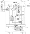
- FIG. 1 shows a configuration of an ultrasonic diagnostic apparatus 1 according to Embodiment 1 of the present invention.
- the ultrasonic diagnostic apparatus 1 includes a transducer array 2, and a transmitter 3 and a receiver 4 are connected to the transducer array 2.
- a B mode processing unit 5 and a Doppler processing unit 6 are connected in parallel to the receiving unit 4, and a display unit 8 is connected to the B mode processing unit 5 and the Doppler processing unit 6 via a display control unit 7.
- the B mode processing unit 5 and the Doppler processing unit 6 constitute an image generation unit 9.
- the blood vessel wall detection unit 10 is connected to the B mode processing unit 5, and the gate setting unit 11 and the cross-sectional area calculation unit 12 are connected to the blood vessel wall detection unit 10.
- the gate setting unit 11 is connected to the Doppler processing unit 6, and the blood flow measurement unit 13 is connected to the cross-sectional area calculation unit 12.
- An average blood flow rate calculation unit 14 is connected to the Doppler processing unit 6, and a blood flow rate measurement unit 13 is connected to the average blood flow rate calculation unit 14.
- the gate setting part 11 and the blood flow rate measurement part 13 are each connected to the display control part.
- the device control unit 15 is connected to the device control unit 15, and the operation unit 16 and the storage unit 17 are connected to the device control unit 15. Further, a position designation receiving unit 18 is connected to the operation unit 16, and the position designation receiving unit 18 is connected to the apparatus control unit 15.
- the device control unit 15 and the storage unit 17 are connected to each other so that bidirectional information can be exchanged.
- the transducer array 2 is included in the ultrasonic probe 20, and includes a transmission unit 3, a reception unit 4, a display control unit 7, an image generation unit 9, a blood vessel wall detection unit 10, a gate setting unit 11, and a cross-sectional area calculation.
- the processor 21 is configured by the unit 12, the blood flow measuring unit 13, the average blood flow velocity calculating unit 14, the device control unit 15, and the position designation receiving unit 18.
- the transducer array 2 of the ultrasonic probe 20 shown in FIG. 1 has a plurality of transducers arranged one-dimensionally or two-dimensionally. Each of these transducers transmits an ultrasonic wave according to the drive signal supplied from the transmission unit 3, receives an ultrasonic echo from the subject, and outputs a signal based on the ultrasonic echo.
- Each vibrator is, for example, a piezoelectric ceramic represented by PZT (Lead Zirconate Titanate), a polymer piezoelectric element represented by PVDF (Poly Vinylidene Di Fluoride) and PMN-PT (polyvinylidene fluoride).
- It is configured by forming electrodes on both ends of a piezoelectric body made of a piezoelectric single crystal represented by Lead Magnesium Niobate-Lead Titanate: lead magnesium niobate-lead titanate solid solution).
- the transmission unit 3 of the processor 21 includes, for example, a plurality of pulse generators, and a plurality of transducers of the transducer array 2 based on a transmission delay pattern selected according to a control signal from the device control unit 15.
- Each of the drive signals is supplied to a plurality of transducers with the delay amount adjusted so that the ultrasonic waves transmitted from the laser beam form an ultrasonic beam.
- a pulsed or continuous wave voltage is applied to the electrodes of the transducers of the transducer array 2
- the piezoelectric material expands and contracts, and pulsed or continuous wave ultrasonic waves are generated from the respective transducers.
- An ultrasonic beam is formed from the synthesized wave of these ultrasonic waves.
- the transmitted ultrasonic beam is reflected by a target such as a part of the subject and propagates toward the transducer array 2 of the ultrasonic probe 20.
- the ultrasonic waves propagating toward the transducer array 2 in this way are received by the respective transducers constituting the transducer array 2.
- each transducer constituting the transducer array 2 expands and contracts by receiving propagating ultrasonic echoes to generate electrical signals, and outputs these electrical signals to the receiving unit 4.
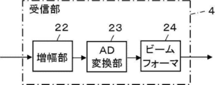
- the receiving unit 4 of the processor 21 processes a signal output from the transducer array 2 in accordance with a control signal from the device control unit 15. As shown in FIG. 2, the receiving unit 4 has a configuration in which an amplifying unit 22, an AD (Analog / Digital) converting unit 23, and a beamformer 24 are connected in series.
- an amplifying unit 22 an AD (Analog / Digital) converting unit 23 and a beamformer 24 are connected in series.
- the amplifying unit 22 amplifies signals input from the respective transducers constituting the transducer array 2 and transmits the amplified signals to the AD converting unit 23.
- the AD conversion unit 23 converts the signal transmitted from the amplification unit 22 into digital data, and transmits these data to the beam former 24.
- the beamformer 24 performs each of the data converted by the AD conversion unit 23 according to the sound speed or the sound speed distribution set based on the reception delay pattern selected according to the control signal from the device control unit 15.
- a so-called reception focus process is performed by adding a delay. With this reception focus processing, each data converted by the AD conversion unit 23 is phased and added, and a reception signal in which the focus of the ultrasonic echo is narrowed down is acquired.
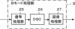
- the B mode processing unit 5 of the image generation unit 9 has a configuration in which a signal processing unit 25, a DSC (Digital Scan Converter) 26, and an image processing unit 27 are sequentially connected in series.
- the signal processing unit 25 corrects attenuation by distance according to the depth of the reflection position of the ultrasonic wave on the reception data generated by the reception unit 4, and then performs an envelope detection process so that the inside of the subject is detected.
- a B-mode image signal which is tomographic image information related to the tissue of, is generated.
- the DSC 26 converts (raster conversion) the B-mode image signal generated by the signal processing unit 25 into an image signal in accordance with a normal television signal scanning method.
- the image processing unit 27 performs various necessary image processing such as gradation processing on the B-mode image signal input from the DSC 26, and then outputs the B-mode image signal to the display control unit 7.
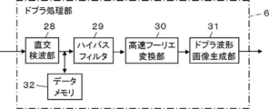
- the Doppler processing unit 6 of the image generation unit 9 calculates a blood flow velocity by a so-called pulse Doppler method and generates a Doppler waveform image.
- the quadrature detection unit 28 and the high-pass filter 29 are used.
- a Fast Fourier Transformer 30 and a Doppler waveform image generator 31 are sequentially connected in series, and a data memory 32 is connected to the output terminal of the orthogonal detector 28.
- the quadrature detection unit 28 mixes the reception data generated by the reception unit 4 with a carrier signal having a reference frequency, thereby performing quadrature detection on the reception data and converting it to complex data.
- the high-pass filter 29 functions as a so-called wall filter, and removes frequency components derived from the motion of the body tissue of the subject from the complex data generated by the quadrature detection unit 28.
- the fast Fourier transform unit 30 performs frequency analysis by Fourier transforming complex data of a plurality of sample points to obtain a blood flow velocity, and generates a spectrum signal.
- the Doppler waveform image generation unit 31 generates a Doppler waveform image signal by expressing the magnitude of each frequency component in luminance while aligning the spectrum signal generated by the fast Fourier transform unit 30 on the time axis.
- the horizontal axis indicates the time axis
- the vertical axis indicates the Doppler shift frequency, that is, the flow velocity
- the luminance of the waveform indicates the power in each frequency component.
- the data memory 32 stores the complex data converted from the reception data by the quadrature detection unit 28.
- the device control unit 15 of the processor 21 controls each unit of the ultrasonic diagnostic apparatus 1 based on a program stored in advance in the storage unit 17 and the like and an operation by the user via the operation unit 16.
- the display control unit 7 of the processor 21 performs predetermined processing on the B-mode image signal generated by the image generation unit 9 under the control of the device control unit 15 to generate an image that can be displayed on the display unit 8.
- the display unit 8 of the ultrasonic diagnostic apparatus 1 displays an image generated by the display control unit 7 and includes a display device such as an LCD (Liquid Crystal Display).
- the operation unit 16 of the ultrasonic diagnostic apparatus 1 is for a user to perform an input operation, and can be configured to include a keyboard, a mouse, a trackball, a touch pad, a touch panel, and the like.
- the position designation receiving unit 18 of the processor 21 receives the designation of the position of the blood vessel region made by the user via the operation unit 16 on the B-mode image displayed on the display unit 8.
- the position designation receiving unit 18 can receive the designation of the position of the blood vessel region touched by the user's finger, stylus pen, or the like.
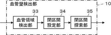
- the blood vessel wall detection unit 10 of the processor 21 detects the blood vessel front wall and the blood vessel rear wall by performing image analysis on the B-mode image based on the specification of the position of the blood vessel region by the user received by the position specification reception unit 18. .
- the blood vessel wall detecting unit 10 has a configuration in which a blood vessel region detecting unit 33, a closed section setting unit 34, and a closed section searching unit 35 are connected in series.
- the upper blood vessel wall that is, the shallow blood vessel wall close to the body surface of the subject in contact with the ultrasonic probe 20
- the lower blood vessel wall that is, the blood vessel wall on the deep side far from the body surface of the subject in contact with the ultrasonic probe 20
- the blood vessel front wall W1 is located on the upper side, that is, the + Y direction side
- the blood vessel rear wall W2 is located on the lower side, that is, the ⁇ Y direction side.
- the blood vessel region detection unit 33 of the blood vessel wall detection unit 10 detects a blood vessel region on the B-mode image UB by performing image analysis on the B-mode image UB generated by the B-mode processing unit 5. At this time, the blood vessel region detection unit 33 can detect a blood vessel region on the B-mode image UB using a known algorithm. For example, the blood vessel region detection unit 33 stores in advance typical pattern data of the blood vessel region as a template, calculates the similarity to the pattern data while searching the template with the template, and the similarity is equal to or greater than the threshold value and the maximum It can be considered that a blood vessel region is present at the location.
- the closed section setting unit 34 of the blood vessel wall detecting unit 10 sets a closed section including the position designated by the user via the position designation receiving unit 18 and through which the blood vessel region detected by the blood vessel region detecting unit 33 passes.
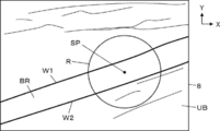
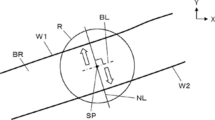
- the closed section setting unit 34 may set a circular closed section R centered on the designated position SP designated by the user via the operation unit 16 on the B-mode image UB. it can.
- the blood vessel region BR passes through the inside of the closed section R.
- the closed section set by the closed section setting unit 34 is not limited to a circle as shown in FIG. 6 as long as it has a closed shape, and can have an arbitrary shape.
- the closed section searching section 35 of the blood vessel wall detecting section 10 detects the blood vessel front wall W1 and the blood vessel rear wall W2 by searching the inside of the closed section set by the closed section setting section 34.
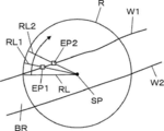
- the closed section searching unit 35 may search the closed section R using a method as disclosed in Japanese Patent No. 4775992 to detect the blood vessel front wall W1 and the blood vessel rear wall W2. it can. Specifically, as shown in FIG. 7, a search connecting the designated position SP and the boundary of the closed section R over the entire 360 ° range centered on the designated position SP designated by the user via the operation unit 16.
- the position where the amount of change in the B-mode intensity is maximized is detected as the position of the blood vessel front wall W1 or the blood vessel rear wall W2.
- the B-mode intensity data for example, the luminance value of the B-mode image signal can be used.
- the search line RL connecting the designated position SP and the boundary of the closed section R is scanned at an angle determined clockwise over 360 degrees around the designated position SP, and the blood vessel front wall W1 and The state of searching for the blood vessel rear wall W2 is shown.
- An edge point EP1 corresponding to the blood vessel front wall W1 is detected on the search line RL1
- an edge point EP2 corresponding to the blood vessel front wall W1 is detected on the search line RL2.
- the gate setting unit 11 of the processor 21 sets a Doppler gate in the blood vessel region BR on the B-mode image based on the blood vessel front wall W1 and the blood vessel rear wall W2 detected by the blood vessel wall detection unit 10.
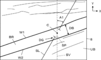
- the gate setting unit 11 can set a Doppler gate using, for example, a method disclosed in Japanese Patent No. 47459592. More specifically, as shown in FIG. 8, the gate setting unit 11 determines the blood vessel region BR on the vertical line SV passing through the designated position SP based on the detected positions of the blood vessel front wall W1 and the blood vessel rear wall W2.
- the center position C is detected, and the Doppler gate DG can be installed so that the center position C and the center of the Doppler gate DG overlap.
- the gate setting unit 11 calculates a line segment that is substantially perpendicular to the blood vessel front wall W1 and the blood vessel rear wall W2, and sets the intersection of the line segment and the vertical line SV as the center position C. Can be detected.
- the vertical line SV is a virtual line extending along the direction perpendicular to the display unit 8, that is, the Y direction.
- the gate setting unit 11 can calculate the blood vessel diameter DB based on the detected positions of the blood vessel front wall W1 and the blood vessel rear wall W2, and can adjust the size of the Doppler gate DG based on the calculated blood vessel diameter DB. it can.
- the Doppler gate DG set by the gate setting unit 11 is tilted by the cursor steer angle A1 from the vertical line SV on the screen of the display unit 8.
- the cursor steer angle A1 indicates the center position C of the Doppler gate DG. It is equal to the inclination angle of the scanning line SL passing through.
- the cross-sectional area calculation unit 12 of the processor 21 calculates the blood vessel diameter DB from the positions of the blood vessel front wall W1 and the blood vessel rear wall W2 detected by the blood vessel wall detection unit 10, and assumes that the blood vessel has a circular cross section.
- the cross-sectional area of the blood vessel is calculated from the diameter DB.
- the average blood flow velocity calculation unit 14 of the processor 21 calculates the average blood flow velocity for one heartbeat period based on the blood flow velocity calculated by the Doppler processing unit 6.
- the blood flow rate measuring unit 13 of the processor 21 is based on the cross-sectional area of the blood vessel calculated by the cross-sectional area calculating unit 12 and the average blood flow velocity calculated by the average blood flow velocity calculating unit 14.
- the blood flow volume representing the volume per unit time is measured.
- the Doppler gate DG set by the gate setting unit 11 and the blood flow information measured by the blood flow measurement unit 13 are sent to the display unit 8 via the display control unit 7 and displayed on the display unit 8.
- the storage unit 17 stores an operation program and the like of the ultrasonic diagnostic apparatus 1, and includes an HDD (Hard Disk Drive), an SSD (Solid State Drive), an FD (Flexible Disk), MO disc (Magneto-Optical disc), MT (Magnetic Tape), RAM (Random Access Memory), CD (Compact Disc), DVD (Digital Versatile Disc)
- HDD Hard Disk Drive
- SSD Solid State Drive
- FD Fluorto-Optical disc
- MT Magnetic Tape
- RAM Random Access Memory
- CD Compact Disc
- DVD Digital Versatile Disc
- a recording medium such as a disk), an SD card (Secure Digital card), a USB memory (Universal Serial Bus memory), a server, or the like can be used.
- the processor 21 having the device control unit 15 and the position designation receiving unit 18 includes a central processing unit (CPU) and a control program for causing the CPU to perform various processes. May be used.
- the processor 21 having the unit 14, the device control unit 15, and the position designation receiving unit 18 may be configured to be partially or wholly integrated into one CPU.
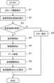
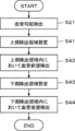
- step S1 a B-mode image UB in which at least the blood vessel region BR is captured is acquired and displayed on the display unit 8.
- an ultrasonic beam is transmitted from a plurality of transducers of the transducer array 2 according to the drive signal from the transmission unit 3, and reception signals are received from the transducers that have received ultrasonic echoes from the subject to the reception unit 4.
- amplified by the amplifying unit 22, AD converted by the AD converting unit 23 the beamformer 24 performs phasing addition to generate reception data.
- the received data is subjected to envelope detection processing by the signal processing unit 25 in the B mode processing unit 5 to become a B mode image signal, which is output to the display control unit 7 via the DSC 26 and the image processing unit 27 for display.
- the B-mode image UB is displayed on the display unit 8 by the control unit 7.
- step S2 first, the blood vessel region detection unit 33 of the blood vessel wall detection unit 10 performs image analysis on the B mode image UB displayed on the display unit 8 in step S1, thereby performing an analysis on the B mode image UB.
- a blood vessel region BR is detected.
- the designated position SP on the B-mode image UB is designated by the user via the operation unit 16, and the designated position SP is accepted by the position designation receiving unit 18.
- the apparatus control unit 15 determines whether or not the designated position SP received in step S2 by the position designation receiving unit 18 is a position in the blood vessel region BR.
- the process proceeds to step S4, an error is displayed on the display unit 8, and the operation of the ultrasonic diagnostic apparatus 1 is finished.
- step S3 If it is determined in step S3 that the designated position SP received in step S2 is a position in the blood vessel region BR, the process proceeds to step S5.
- step S5 the blood vessel wall detection unit 10 performs image analysis on the B mode image UB displayed on the display unit 8 in step S1, thereby causing the blood vessel front wall W1 and the blood vessel rear wall W2 on the B mode image UB. Is detected.
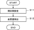
- the blood vessel wall detection unit 10 detects the blood vessel front wall W1 and the blood vessel rear wall W2 by performing the processing shown in the flowchart of FIG.
- step S11 the closed section setting unit 34 of the blood vessel wall detecting unit 10 sets a closed section R including the designated position SP accepted in step S2 and through which the blood vessel region BR passes.
- step S12 the closed section searching unit 35 of the blood vessel wall detecting unit 10 searches the closed section R set in step S11 as shown in FIG.
- the wall W2 is detected.
- the closed section searching unit 35 searches outward on the search line RL while rotating the search line RL connecting the boundary between the designated position SP and the closed section R over a predetermined angle by 360 °.
- the blood vessel front wall W1 and the blood vessel rear wall W2 are detected by detecting the edge points of the blood vessel front wall W1 and the blood vessel rear wall W2 at which the amount of change in B-mode intensity on the RL becomes a maximum value. In this way, the processing of step S5 is performed by the blood vessel wall detection unit 10.
- the cross-sectional area calculation unit 12 calculates the blood vessel diameter DB based on the positions of the blood vessel front wall W1 and the blood vessel rear wall W2 detected in step S5, and the blood vessel is circular.
- the cross-sectional area of the blood vessel is calculated from the blood vessel diameter DB.
- the gate setting unit 11 sets a Doppler gate DG on the B-mode image UB as shown in FIG. At this time, the gate setting unit 11 can set the Doppler gate DG on the B-mode image UB by using, for example, the method disclosed in Japanese Patent No. 47459592.
- step S8 information on the Doppler gate DG set in Step S7 is output from the gate setting unit 11 to the Doppler processing unit 6 of the image generation unit 9, and the Doppler processing unit 6 performs Doppler in the area sandwiched between the Doppler gates DG.
- a blood flow velocity is calculated based on the data, and a Doppler waveform image is generated.
- the average blood flow velocity calculation unit 14 calculates the average blood flow velocity for one heartbeat period based on the calculated blood flow velocity.
- step S9 the blood flow measurement unit 13 per unit time of blood flowing in the blood vessel based on the cross-sectional area of the blood vessel calculated in step S6 and the average blood flow velocity in one heartbeat period calculated in step S8.
- the blood flow representing the volume of the blood is measured, and the measurement result is displayed on the display unit 8.
- the blood flow measurement unit 13 sets the blood vessel cross-sectional area to CSA (cm 2 ) and the average blood flow velocity to MNV (m / s). / Min) can be calculated by the following equation (1).
- VF CSA ⁇ MNV ⁇ 60 (s / min) ⁇ 100 (cm / m) (1)
- the blood flow rate measurement part 13 can display a measurement result as FIG. 11 shows, for example.
- the Doppler waveform image UD generated in step S8 and the blood flow measurement value MV are displayed side by side with the B-mode image UB.
- the user can check the blood flow measured by the blood flow measurement unit 13 while observing the B-mode image UB and the Doppler waveform image UD displayed on the display unit 8. Thereby, the operation of the ultrasonic diagnostic apparatus 1 is completed.
- the ultrasound diagnostic apparatus 1 when the user designates the position of the blood vessel region BR on the B-mode image UB displayed on the display unit 8 via the operation unit 16. Since the blood flow measurement result is automatically displayed on the display unit 8, the blood flow can be measured easily and in a short time.
- the blood vessel region BR can be displayed on the display unit 8 when the user designates the position of the blood vessel region BR via the operation unit 16.
- the blood vessel region detection unit 33 gives an arbitrary color to the blood vessel region BR on the B mode image UB displayed on the display unit 8, and surrounds the blood vessel region BR with a line such as a solid line or a broken line.
- the blood vessel region BR can be displayed on the display unit 8. As a result, the user can more easily grasp the blood vessel region BR on the B-mode image UB displayed on the display unit 8.
- the blood vessel region detection unit 33 of the blood vessel wall detection unit 10 detects the blood vessel region BR in advance before the user designates the designated position SP on the B-mode image UB via the operation unit 16.
- the closed section setting unit 34 of the blood vessel wall detecting unit 10 sets the closed section R including the designated position SP, and the blood vessel region detecting unit 33 performs image analysis on the B-mode image UB in the closed section R. Accordingly, the blood vessel region BR can be detected.
- the blood vessel region detection unit 33 may detect the blood vessel region BR by performing image analysis over the entire B-mode image UB without setting the closed section R.
- the front wall detection unit 37 and the rear wall detection unit 38 detect the blood vessel front wall W1 and the blood vessel rear wall W2 by detecting edge points in the closed section R.
- the contours of the blood vessel region BR in the section R the contour of the blood vessel region BR positioned in the shallow direction is detected as the blood vessel front wall W1
- the contour of the blood vessel region BR positioned in the deep direction is detected as the blood vessel rear wall W2. You can also.
- the display unit 8 can switch the display of the Doppler waveform image UD and the B-mode image UB and the display of the blood flow measurement value MV so that they can be displayed separately.
- the ultrasound diagnostic apparatus 1 is provided with a display screen different from the display unit 8, and a B-mode image UB is displayed on either the display screen or the display unit 8, and the Doppler waveform is displayed on the other side.
- the image UD and the blood flow measurement value MV can also be displayed.
- Embodiment 2 In the first embodiment of the present invention, the blood vessel front wall W1 and the blood vessel rear wall W2 are detected by performing image analysis on the B-mode image UB, as in the method disclosed in Japanese Patent No. 4745592. Although the blood vessel front wall W1 and the blood vessel rear wall W2 can also be detected using a blood vessel gradient.
- the ultrasonic diagnostic apparatus according to the second embodiment of the present invention is shown in FIG. 1 except that a blood vessel wall detecting unit 10A is provided instead of the blood vessel wall detecting unit 10 in the first embodiment shown in FIG. It has the same apparatus configuration as the ultrasonic diagnostic apparatus 1.
- the blood vessel wall detecting unit 10A includes a blood vessel region detecting unit 33, a blood vessel gradient detecting unit 36, a front wall detecting unit 37, and a rear wall detecting unit 38. It has the structure connected in series.
- the blood vessel region detection unit 33 is the same as the blood vessel region detection unit 33 in the first embodiment shown in FIG.
- the blood vessel gradient detecting unit 36 of the blood vessel wall detecting unit 10A is based on the blood vessel region BR detected by the blood vessel region detecting unit 33, and within a predetermined range including the designated position SP designated by the user via the operation unit 16.
- a blood vessel gradient that is a running direction of the blood vessel is detected.
- the blood vessel gradient detecting unit 36 performs image analysis on the blood vessel region BR on the B-mode image UB in the closed section including the designated position SP designated by the user, as shown in FIG.
- a blood vessel gradient line BL representing the gradient is detected.
- the blood vessel gradient detecting unit 36 can detect the inertial main axis of the blood vessel region BR, for example, as the blood vessel gradient line BL.
- the front wall detection unit 37 of the blood vessel wall detection unit 10A is shallower than the designated position SP along the gradient vertical line NL perpendicular to the blood vessel gradient line BL detected by the blood vessel gradient detection unit 36.
- the blood vessel front wall W1 is detected.
- the front wall detection unit 37 has a location where the change amount of the B-mode intensity reaches a maximum value in a range having a length determined in the shallow direction along the gradient vertical line NL from the designated position SP. Is detected as the blood vessel front wall W1.
- the rear wall detection unit 38 of the blood vessel wall detection unit 10 ⁇ / b> A generates a gradient vertical line NL perpendicular to the blood vessel gradient line BL detected by the blood vessel gradient detection unit 36, as in the case of the front wall detection unit 37.
- the blood vessel posterior wall W2 is detected by performing image analysis in a deeper direction than the designated position SP.
- the front wall detection unit 37 detects a portion where the amount of change in the B mode intensity becomes a maximum value in a range having a length determined in the deep direction along the gradient vertical line NL from the designated position SP. It is detected as a blood vessel rear wall W2.
- the blood vessel gradient detecting unit 36 of the blood vessel wall detecting unit 10A performs image analysis on the blood vessel region BR on the B-mode image UB in the closed section including the designated position SP designated by the user.
- the blood vessel gradient detection unit 36 can detect the inertial main axis of the blood vessel region BR in the closed section R as a blood vessel gradient line BL representing the blood vessel gradient.
- the blood vessel front wall W1 is detected by the front wall detection unit 37 of the blood vessel wall detection unit 10A, and the blood vessel rear wall W2 is detected by the rear wall detection unit 38.
- the front wall detection unit 37 detects a gradient perpendicular to the blood vessel gradient line BL detected in step S22 from the designated position SP designated by the user via the operation unit 16. In a range having a length defined in the shallow direction along the vertical line NL, a portion where the amount of change in B-mode intensity reaches a maximum value is detected as the blood vessel front wall W1.
- the rear wall detection unit 38 has a B-mode intensity in a range having a length determined in the depth direction along the gradient vertical line NL from the designated position SP. A location where the amount of change is a maximum value is detected as the blood vessel rear wall W2. In this way, the blood vessel front wall W1 and the blood vessel rear wall W2 can be detected in a more limited range along the gradient vertical line NL. Thereby, the blood vessel wall detection operation in the second exemplary embodiment of the present invention is completed.
- the ultrasonic diagnostic apparatus of the second embodiment of the present invention by performing image analysis on the B-mode image UB, the blood vessel gradient line BL representing the blood vessel gradient is detected and is perpendicular to the blood vessel gradient line BL. Since the blood vessel front wall W1 and the blood vessel rear wall W2 are detected along the gradient vertical line NL, the range used for detecting the blood vessel front wall W1 and the blood vessel rear wall W2 is further limited, and the calculation load of the ultrasonic diagnostic apparatus is reduced. Can be reduced. Thereby, the blood vessel front wall W1 and the blood vessel rear wall W2 can be detected in a shorter time.
- the closed section R as shown in FIG. 6 is not set.
- the front wall detection unit 37 and the rear wall detection unit are not set. 38 sets a closed section R, and in this closed section R, by searching the gradient vertical line NL while moving the gradient vertical line NL in a direction parallel to the blood vessel gradient line BL, the blood vessel front wall W1 It is also possible to detect the blood vessel rear wall W2.
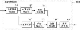
- FIG. 15 shows an internal configuration of the blood vessel wall detection unit 10B used in the ultrasonic diagnostic apparatus according to the third embodiment.
- the blood vessel wall detection unit 10B includes a blood vessel region detection unit 33, a blood vessel gradient detection unit 36, an image rotation unit 39, a smoothing unit 40, a front wall detection unit 37, a rear wall detection unit 38, and a coordinate acquisition unit. 41 are connected in series.
- the ultrasonic diagnostic apparatus according to the third embodiment uses the blood vessel wall detecting unit 10B instead of the blood vessel wall detecting unit 10 in the ultrasonic diagnostic apparatus 1 according to the first embodiment shown in FIG. Except the detection unit 10B, the configuration is the same as that of the ultrasound diagnostic apparatus 1 of the first embodiment.
- the blood vessel region detection unit 33 of the blood vessel wall detection unit 10B shown in FIG. 15 is the same as the blood vessel region detection unit 33 of the blood vessel wall detection unit 10 shown in FIG. 5, and the blood vessel gradient detection unit 36 of the blood vessel wall detection unit 10B.
- the front wall detection unit 37 and the rear wall detection unit 38 are the same as the blood vessel gradient detection unit 36, the front wall detection unit 37, and the rear wall detection unit 38 of the blood vessel wall detection unit 10A shown in FIG.
- the image rotation unit 39 of the blood vessel wall detection unit 10B rotates the B-mode image UB by the blood vessel gradient detected by the blood vessel gradient detection unit 36 so that the blood vessel region BR extends horizontally on the screen of the display unit 8.
- the image rotation unit 39 rotates the B-mode image UB so that the blood vessel region BR extends horizontally on the screen of the display unit 8, that is, the blood vessel gradient line BL representing the blood vessel gradient extends along the X direction.
- a B-mode image UB1 as shown in FIG. 16 is acquired.
- the smoothing unit 40 of the blood vessel wall detection unit 10B performs a smoothing process along the horizontal direction on the B-mode image UB1 acquired by the image rotation unit 39.
- the front wall detection unit 37 and the rear wall detection unit 38 of the blood vessel wall detection unit 10B are respectively rotated in the same manner as the front wall detection unit 37 and the rear wall detection unit 38 of the blood vessel wall detection unit 10A in the second embodiment.
- the blood vessel front wall W1 and the blood vessel rear wall W2 are detected in the B-mode image UB1 acquired by the unit 39.
- the coordinate acquisition unit 41 of the blood vessel wall detection unit 10B reversely rotates the B-mode image UB1 acquired by the image rotation unit 39 by the blood vessel gradient before being rotated by the image rotation unit 39 to obtain the original B-mode image UB. In this case, the coordinates of the blood vessel front wall W1 and the blood vessel rear wall W2 are acquired.
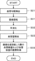
- the blood vessel gradient detecting unit 36 of the blood vessel wall detecting unit 10B includes the blood vessel region BR on the B-mode image UB within a predetermined section including the designated position SP designated by the user via the operation unit 16.
- a blood vessel gradient line BL representing a blood vessel gradient is detected by performing image analysis on the image.
- the image rotation unit 39 of the blood vessel wall detection unit 10B causes the blood vessel region BR to extend along the horizontal direction in the display unit 8, that is, the blood vessel gradient line BL detected in step S21 is X.
- the B-mode image UB1 is acquired by rotating the B-mode image UB by the blood vessel gradient so as to extend along the direction.
- the blood vessel region BR extends in the horizontal direction on the screen of the display unit 8, that is, in a direction inclined by the inclination of the blood vessel gradient line BL with respect to the X direction. ing.
- the blood vessel region BR extends in the horizontal direction, that is, in the X direction on the screen of the display unit 8 as shown in FIG.
- a B-mode image UB1 is acquired.
- the smoothing unit 40 performs a smoothing process along the horizontal direction on the B-mode image UB1.
- the smoothing process is a process for removing noise in the B-mode image UB1 by smoothing the luminance value at each point of the B-mode image UB1, and includes, for example, a moving average filter and a Gaussian smoothing. It can implement by using smoothing filters, such as a filter and a median filter.
- the blood vessel region BR extends in the horizontal direction
- the blood vessel front wall W1 and the blood vessel rear wall W2 also extend in the horizontal direction
- the blood vessel region BR extends in the horizontal direction.
- the blood vessel front wall W1 and the blood vessel rear wall W2 are detected on the B-mode image UB1 by the front wall detection unit 37 and the rear wall detection unit 38 in the subsequent step S22.
- the front wall detection unit 37 starts from the designated position SP designated by the user via the operation unit 16 along the gradient vertical line NL perpendicular to the blood vessel gradient line BL.
- a portion where the amount of change in B-mode intensity reaches a maximum value is detected as the blood vessel front wall W1.
- the blood vessel gradient line BL extends along the horizontal direction on the screen of the display unit 8, that is, the X direction
- the gradient vertical line NL is the vertical direction on the screen of the display unit 8. That is, it extends along the Y direction.
- the rear wall detection unit 38 for example, similarly to the front wall detection unit 37, the amount of change in B-mode intensity in a range having a length determined in the deep direction along the gradient vertical line NL from the designated position SP. Is detected as the blood vessel rear wall W2.
- step S33 the coordinate acquisition unit 41 reversely rotates the B-mode image UB1 by the inclination of the blood vessel gradient line BL in the B-mode image UB before being rotated in step S31, that is, the inclination of the blood vessel gradient line BL.
- the coordinates of the blood vessel front wall W1 and the blood vessel rear wall W2 when the B-mode image UB1 is reversely rotated so as to match the initial inclination are acquired.
- the coordinate acquisition unit 41 performs, for example, a coordinate conversion operation on the coordinates of the blood vessel front wall W1 and the blood vessel rear wall W2 in the B mode image UB1, so that only the initial inclination of the blood vessel gradient line BL is in the B mode.
- the coordinates of the blood vessel front wall W1 and the blood vessel rear wall W2 when the image UB1 is rotated in the reverse direction can be calculated. In this way, when the coordinates of the blood vessel front wall W1 and the blood vessel rear wall W2 are acquired in the smoothed B-mode image UB, the blood vessel wall detection operation in the third embodiment ends.
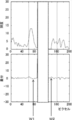
- FIG. 19 shows an example of the profile of the difference in luminance (change amount) between adjacent points on the profile and the gradient vertical line NL.
- the blood vessel front wall W1 and the blood vessel rear wall W2 are detected. From the detected blood vessel front wall W1 and blood vessel rear wall W2, the blood vessel diameter was calculated as 3.67 mm.
- FIG. 20 shows an example of a profile of a difference in luminance (change amount) between adjacent points on the vertical line NL. Based on the luminance difference, the blood vessel front wall W1 and the blood vessel rear wall W2 were detected, and the blood vessel diameter was calculated as 3.39 mm from the detected blood vessel front wall W1 and blood vessel rear wall W2. It can be seen that the luminance profile shown in FIG. 19 has a sharper shape than the luminance profile shown in FIG.
- the B-mode image UB is subjected to the smoothing process along the horizontal direction with respect to the B-mode image UB in which the blood vessel region BR extends in the direction inclined by the initial blood vessel gradient with respect to the horizontal direction.
- the blood vessel diameter is calculated to be smaller than when the smoothing process along the horizontal direction is performed on the rotated B-mode image UB1.
- the blood vessel cross-sectional area is calculated using the blood vessel diameter calculated by the luminance profile shown in FIG. 19, and when the blood vessel cross-sectional area is calculated using the blood vessel diameter calculated by the luminance profile shown in FIG.
- the blood flow measured by the blood flow measuring unit 13 is compared, the blood flow when using the luminance profile shown in FIG. 19 is approximately less than the blood flow using the luminance profile shown in FIG. It fell by 15%.
- the B-mode image UB is rotated so that the blood vessel gradient line BL extends along the horizontal direction on the screen of the display unit 8.
- the coordinate acquisition unit 41 performs coordinate conversion on the coordinates of the blood vessel front wall W1 and the blood vessel rear wall W2 on the B mode image UB1, thereby converting the B mode image UB1 into the original blood vessel gradient.
- the method of calculating the coordinates of the blood vessel front wall W1 and the blood vessel rear wall W2 is not limited to this.
- the coordinate acquisition unit 41 can reversely rotate the B-mode image UB1 by the initial blood vessel gradient, and can acquire the coordinates of the blood vessel front wall W1 and the blood vessel rear wall W2 on the reversely rotated B-mode image.
- FIG. 21 shows an internal configuration of the blood vessel wall detection unit 10C used in the ultrasonic diagnostic apparatus according to the fourth embodiment.
- the blood vessel wall detection unit 10C includes a blood vessel region detection unit 33, a blood vessel gradient detection unit 36, an upper detection region setting unit 42, a lower detection region setting unit 43, a front wall detection unit 37, and a rear wall detection unit 38. Are connected in series.
- the ultrasonic diagnostic apparatus according to the fourth embodiment uses the blood vessel wall detecting unit 10C instead of the blood vessel wall detecting unit 10 in the ultrasonic diagnostic apparatus 1 of the first embodiment shown in FIG. Except for the detection unit 10C, the configuration is the same as that of the ultrasonic diagnostic apparatus 1 of the first embodiment.
- the blood vessel region detection unit 33 of the blood vessel wall detection unit 10C is the same as the blood vessel region detection unit 33 of the blood vessel wall detection unit 10 shown in FIG. 5, and the blood vessel gradient detection unit 36 and the front wall detection of the blood vessel wall detection unit 10C.
- the unit 37 and the rear wall detection unit 38 are the same as the blood vessel gradient detection unit 36, the front wall detection unit 37, and the rear wall detection unit 38 of the blood vessel wall detection unit 10A shown in FIG.
- the upper detection region setting unit 42 of the blood vessel wall detection unit 10C sets the upper reference point P1 based on the contour position of the blood vessel region BR, and uses the set upper reference point P1 as a reference.
- the upper detection area R1 is set.
- the upper reference point P1 is a point set in the blood vessel region BR that is shallower than the designated position SP and on the gradient vertical line NL.
- the upper detection region R1 is a region for searching the blood vessel front wall W1, and extends in the shallow direction by the length H1 from the upper reference point P1 along the gradient vertical line NL so as to extend inside and outside the blood vessel region BR.
- the upper reference point P1 has a rectangular shape extending along a direction parallel to the direction along the blood vessel gradient line BL by a length L1 so that the upper reference point P1 becomes the center.
- the upper reference point P1 is set to be located inside the blood vessel region BR by, for example, about 1 to 2 mm from the outline of the blood vessel region BR.
- the lower detection region setting unit 43 of the blood vessel wall detection unit 10C sets the lower reference point P2 based on the contour position of the blood vessel region BR, and sets the lower detection region based on the set lower reference point P2.
- the lower reference point P2 is a point that is set deeper than the designated position SP and on the gradient vertical line NL in the blood vessel region BR.
- the lower detection region R2 is a region for searching the blood vessel rear wall W2, and extends in the deep direction from the lower reference point P2 by a length H2 along the gradient vertical line NL so as to extend inside and outside the blood vessel region BR.
- the lower reference point P2 has a rectangular shape extending along a direction parallel to the direction along the blood vessel gradient line BL by a length L2 so that the lower reference point P2 is in the center.
- the lower reference point P2 is set so as to be positioned inside the blood vessel region BR by about 1 to 2 mm from the contour of the blood vessel region BR.
- the front wall detection unit 37 and the rear wall detection unit 38 are respectively the intensity (luminance) of the B-mode image signal at each point in the upper detection region R1 and the lower detection region R2, and the intensity of the B-mode image signal at each point. It is possible to detect the blood vessel front wall boundary line and the blood vessel rear wall boundary line based on the change amount of. For example, although not shown, the front wall detection unit 37 moves a search line parallel to the gradient vertical line NL in the upper detection region R1 in a direction parallel to the blood vessel gradient line BL, while shallowly moving the search line on the search line. By searching in the direction, a portion where the amount of change in the B-mode intensity becomes maximum can be detected as the blood vessel front wall W1.
- the rear wall detection unit 38 searches in the deep direction on the search line while moving the search line parallel to the gradient vertical line NL in the direction parallel to the blood vessel gradient line BL in the lower detection region R2. By doing so, the location where the amount of change in the B-mode intensity becomes maximum can be detected as the blood vessel rear wall W2.
- the blood vessel front wall boundary line and the blood vessel rear wall boundary are obtained using dynamic programming. Lines can also be detected. Furthermore, as disclosed in International Publication 2011 / 099102A1, it is possible to detect a blood vessel front wall boundary line and a blood vessel rear wall boundary line using a pattern similarity based on a template indicating a reference pattern of a blood vessel wall.
- a wall boundary candidate point is determined, and a first evaluation value representing the accuracy of the determined blood vessel wall boundary candidate point as a blood vessel wall boundary point is calculated and determined using luminance information, particularly intensity information and edge information.
- a second evaluation value that represents the similarity with the adjacent search line that includes the selected blood vessel wall boundary candidate point, and among the blood vessel wall boundary candidate points based on the first evaluation value and the second evaluation value It is also possible to calculate a third evaluation value for determining a blood vessel wall boundary point from the above, and detect a blood vessel front wall boundary line and a blood vessel rear wall boundary line.
- the “second evaluation value” a jump amount in the depth direction between the search lines of the determined blood vessel wall boundary candidate points may be used instead of the similarity. That is, a vascular wall boundary candidate point is determined on each search line, a first evaluation value representing the accuracy of the determined vascular wall boundary candidate point as a vascular wall boundary point is calculated, and the determined vascular wall boundary candidate point is determined.
- a second evaluation value based on the amount of jump in the depth direction between the search lines is calculated, and the blood vessel wall boundary point is selected from the blood vessel wall boundary candidate points based on the first evaluation value and the second evaluation value.
- a third evaluation value for determination may be calculated to detect the blood vessel front wall boundary line and the blood vessel rear wall boundary line.
- step S21 the blood vessel gradient detecting unit 36 of the blood vessel wall detecting unit 10C performs image analysis on the blood vessel region BR within a predetermined range including the designated position SP designated by the user via the operation unit 16. By applying, a blood vessel gradient line BL representing a blood vessel gradient is detected.
- step S41 the upper detection region setting unit 42 of the blood vessel wall detection unit 10C sets and sets the upper reference point P1 on the gradient vertical line NL shallower than the designated position SP in the blood vessel region BR.
- the upper detection area R1 is set on the B-mode image with the upper reference point P1 set as a reference.
- step S42 the front wall detection unit 37 of the blood vessel wall detection unit 10C detects the blood vessel front wall W1 by searching for the upper detection region R1 on the B-mode image set in step S41.
- step S43 the lower detection region setting unit 43 of the blood vessel wall detection unit 10C sets the lower reference point P2 deeper than the specified position SP and on the gradient vertical line NL in the blood vessel region BR.
- the lower detection area R2 is set on the B-mode image with the side reference point P2 as a reference.
- step S44 the rear wall detection unit 38 of the blood vessel wall detection unit 10C detects the blood vessel rear wall W2 by searching the lower detection region R2 on the B-mode image set in step S43.
- the blood vessel wall detection operation in the fourth embodiment ends.
- the upper detection area R1 and the lower detection area R2 with the upper reference point P1 and the lower reference point P2 set inside the blood vessel area BR as references.
- the maximum point of the B mode intensity due to multiple reflection of ultrasonic waves Even if appears, the blood vessel front wall W1 and the blood vessel rear wall W2 can be accurately detected without erroneously detecting this local maximum point.
- the length H1 and the length L1 of the upper detection region R1 and the length H2 and the length L2 of the lower detection region R2 may have the same value or may be different from each other. Good. Further, the upper detection region R1 and the lower detection region R2 are not limited to rectangular shapes, and are not limited to the shapes of the upper detection region R1 and the lower detection region R2.
- the horizontal smoothing process is performed on the B-mode image UB1 obtained by rotating the B-mode image UB by the blood vessel gradient. Later, the blood vessel front wall W1 and the blood vessel rear wall W2 can be detected by searching the upper detection region R1 and the lower detection region R2. In this way, it is possible to more accurately detect the blood vessel front wall W1 and the blood vessel rear wall W2 and to measure an accurate blood flow rate.
- FIG. 24 shows a configuration of an ultrasonic diagnostic apparatus 1A according to the fifth embodiment.
- This ultrasonic diagnostic apparatus 1A uses the blood vessel wall detecting unit 10A in the second embodiment shown in FIG. 12 in place of the blood vessel wall detecting unit 10 in the ultrasonic diagnostic apparatus 1 in the first embodiment shown in FIG.
- a correction receiving unit 19 is further provided.
- the gradient correction receiving unit 19 is connected to the operation unit 16, and the device control unit 15 is connected to the gradient correction receiving unit 19.
- the processor control unit 15, the position designation receiving unit 18 and the gradient correction receiving unit 19 constitute a processor 21 ⁇ / b> A.
- the blood vessel gradient detection unit 36 of the blood vessel wall detection unit 10A generates a blood vessel gradient line BL substantially parallel to the traveling direction of the tube in a predetermined range including the designated position SP designated by the user via the operation unit 16.
- the user can finely adjust the inclination of the blood vessel gradient line BL via the operation unit 16.
- the user can change the inclination of the blood vessel gradient line BL by using the gradient correction dial as the operation unit 16 and rotating the gradient correction dial.
- the gradient correction receiving unit 19 of the processor 21A receives such correction of the inclination of the blood vessel gradient line BL by the user via the operation unit 16.
- the front wall detection unit 37 and the rear wall detection unit 38 of the blood vessel wall detection unit 10C are based on the correction of the inclination of the blood vessel gradient line BL received by the gradient correction reception unit 19 and the corrected blood vessel gradient line BL.
- the cross-sectional area calculation unit 12 of the processor 21A recalculates the blood vessel diameter based on the positions of the blood vessel front wall W1 and the blood vessel rear wall W2 detected by the front wall detection unit 37 and the rear wall detection unit 38, and calculates the calculated blood vessel diameter. Based on the above, the cross-sectional area of the blood vessel is calculated.
- the average blood flow velocity calculation unit 14 of the processor 21A recalculates the average blood flow velocity based on the inclination of the blood vessel gradient line BL corrected by the user via the operation unit 16.
- the blood flow rate measurement unit 13 of the processor 21A calculates a mathematical formula based on the cross-sectional area of the blood vessel recalculated by the cross-sectional area calculation unit 12 and the average blood flow velocity re-calculated by the average blood flow velocity calculation unit 14.
- the blood flow VF is recalculated by using (1).
- the user corrects the blood vessel gradient automatically detected by the blood vessel gradient detecting unit 36 of the blood vessel wall detecting unit 10A via the operation unit 16. Since the blood flow VF is calculated on the basis of the corrected blood vessel gradient, it is possible to obtain a more accurate blood flow VF.
- the use of a gradient correction dial as the operation unit 16 has been described.
- the user can manually adjust the inclination of the blood vessel gradient line BL. If it can correct, it will not be limited to this method.
- a gradient correction button for adjusting the inclination of the blood vessel gradient line BL as the operation unit 16 and changing the inclination of the blood vessel gradient line BL by a predetermined angle each time the user presses the gradient correction button, The inclination of the blood vessel gradient line BL can also be finely adjusted.
- a virtual gradient correction dial, a gradient correction button, and the like are displayed on the display unit 8, and the user can make a virtual gradient.
- the correction dial, the gradient correction button, etc. the inclination of the blood vessel gradient line BL can be finely adjusted.
- the blood vessel front wall W1 and the blood vessel rear wall W2 are detected again based on the inclination of the blood vessel gradient line BL finely adjusted by the user via the operation unit 16.
- the blood flow can be measured again without redetecting the front wall W1 and the blood vessel rear wall W2.
- the scale of the pulse Doppler in the Doppler processing unit 6 is changed, and the average blood flow rate calculation unit 14 recalculates the average blood flow rate, and this average blood flow
- the blood flow measurement unit 13 can measure the blood flow again using the velocity and the cross-sectional area of the blood vessel calculated by the cross-sectional area calculation unit 12 before finely adjusting the inclination of the blood vessel gradient line BL.
- the ultrasonic diagnostic apparatus according to the first to fifth embodiments described above can be applied to a portable ultrasonic diagnostic apparatus that uses the touch sensor as the operation unit 16 by combining the display unit 8 with a touch sensor. If such a portable ultrasonic diagnostic apparatus is used, it can be effectively used for outdoor diagnosis during emergency treatment or the like.
Abstract
容易に且つ短時間に血流量の測定を行うことができる超音波診断装置および超音波診断装置の制御方法を提供する。超音波診断装置(1)は、少なくとも血管領域が撮像されているBモード画像を表示する表示部(8)と、Bモード画像上における血管領域の位置の指定を受け付ける位置指定受付部(18)と、指定された血管領域の位置に基づいてBモード画像を画像解析して血管壁を検出する血管壁検出部(10)と、検出された血管壁に基づいて血管の断面積を算出する断面積算出部(12)と、検出された血管壁に基づいてBモード画像上の血管領域内にドプラゲートを設定するゲート設定部(11)と、ドプラゲート内のドプラデータに基づいて血流速度を算出するドプラ処理部(6)と、血管の断面積と血流速度に基づいて血流量を計測し計測結果を表示部(8)に表示する血流量計測部(13)とを備える。
Description
本発明は、超音波診断装置および超音波診断装置の制御方法に係り、特に、Bモード画像において血管壁の検出を行う超音波診断装置および超音波診断装置の制御方法に関する。
従来から、被検体の内部の画像を得るものとして、超音波診断装置が知られている。超音波診断装置は、一般的に、複数の素子が配列された振動子アレイが備えられた超音波プローブを備えている。この超音波プローブを被検体の体表に接触させた状態において、振動子アレイから被検体内に向けて超音波ビームが送信され、被検体からの超音波エコーを振動子アレイにおいて受信して素子データが取得される。さらに、超音波診断装置は、得られた素子データを電気的に処理して、被検体の当該部位に対する超音波画像を生成する。
例えば、特許文献1には、Bモード画像上にドプラゲートを設置し、ドプラゲートの中心点を中心とする円形の探索領域を設定し、探索領域の360°の全範囲にわたって半径線に沿って中心から外向きにBモード強度データを探索することにより、血管壁を検出する超音波診断装置が開示されている。
特許文献1の超音波診断装置によれば、検出した血管壁に基づいてドプラゲートの位置およびサイズを調整し、且つ最適なステアリング角を選択することができる。
しかしながら、例えば、特許文献1に開示されている超音波診断装置において血流量を測定する場合には、ドプラゲートを用いて血流速度を測定することはできるものの、血流速度の測定に加えて、別途、血管の断面積の測定を行い、測定した断面積と血流速度に基づいて血流量を計算する必要がある。このように、ユーザは、血流量を得るために、超音波診断装置に対して追加の操作を行わなければならず、多大な手間と時間を要していた。
しかしながら、例えば、特許文献1に開示されている超音波診断装置において血流量を測定する場合には、ドプラゲートを用いて血流速度を測定することはできるものの、血流速度の測定に加えて、別途、血管の断面積の測定を行い、測定した断面積と血流速度に基づいて血流量を計算する必要がある。このように、ユーザは、血流量を得るために、超音波診断装置に対して追加の操作を行わなければならず、多大な手間と時間を要していた。
本発明は、このような従来の問題点を解消するためになされたものであり、容易に且つ短時間に血流量の測定を行うことができる超音波診断装置および超音波診断装置の制御方法を提供することを目的とする。
上記目的を達成するために、本発明に係る超音波診断装置は、少なくとも血管領域が撮像されているBモード画像を表示する表示部と、ユーザによりBモード画像上における血管領域の位置の指定を受け付ける位置指定受付部と、位置指定受付部が受け付けたユーザによる血管領域の位置の指定に基づいてBモード画像を画像解析することにより血管前壁および血管後壁を検出する血管壁検出部と、血管壁検出部により検出された血管前壁および血管後壁に基づいて血管の断面積を算出する断面積算出部と、血管壁検出部により検出された血管前壁および血管後壁に基づいてBモード画像上における血管領域内にドプラゲートを設定するゲート設定部と、ドプラゲート内のドプラデータに基づいて血流速度を算出するドプラ処理部と、断面積算出部により算出された血管の断面積とドプラ処理部により算出された血流速度に基づいて血流量を計測し且つ計測結果を表示部に表示する血流量計測部とを備え、位置指定受付部がユーザによる血管領域の位置の指定を受け付けると、血流量の計測結果が表示部に自動的に表示されることを特徴とする。
血管壁検出部は、Bモード画像を画像解析することにより血管領域を検出する血管領域検出部と、位置指定受付部を介してユーザにより指定された位置を含み且つ血管領域検出部により検出された血管領域が内部を通る閉区間を設定する閉区間設定部とを含み、閉区間設定部により設定された閉区間内において血管前壁および血管後壁を検出することができる。
この際に、血管壁検出部は、閉区間内における血管領域の輪郭を血管前壁および血管後壁として検出することができる。
この際に、血管壁検出部は、閉区間内における血管領域の輪郭を血管前壁および血管後壁として検出することができる。
もしくは、血管壁検出部は、血管領域検出部により検出された血管領域に基づいて血管勾配を検出する血管勾配検出部を含み、血管勾配検出部により検出された血管勾配に対して垂直な方向に探索することにより血管前壁および血管後壁を検出することもできる。
さらに、血管壁検出部は、血管勾配検出部により検出された血管勾配に対して垂直に延びる勾配垂直線に沿って探索することにより血管前壁および血管後壁を検出することができる。
もしくは、血管壁検出部は、閉区間内における血管領域の輪郭に基づいてそれぞれ定められた範囲を有する上側検出領域および下側検出領域を設定し、上側検出領域内において血管前壁を検出し、下側検出領域内において血管後壁を検出することもできる。
もしくは、血管壁検出部は、閉区間内における血管領域の輪郭に基づいてそれぞれ定められた範囲を有する上側検出領域および下側検出領域を設定し、上側検出領域内において血管前壁を検出し、下側検出領域内において血管後壁を検出することもできる。
また、血管壁検出部は、血管領域が水平に延びるように、血管勾配検出部により検出された血管勾配だけBモード画像を回転する画像回転部と、画像回転部により回転されたBモード画像に対して水平方向に沿った平滑化処理を行う平滑化部を含み、血管壁検出部は、平滑化部により平滑化されたBモード画像上において血管前壁および血管後壁を検出することができる。
また、ユーザにより血管勾配の修正を受け付ける勾配修正受付部をさらに備え、血管壁検出部は、勾配修正受付部が受け付けたユーザによる血管勾配の修正に基づいて修正された血管勾配に対して垂直な方向に探索することにより血管前壁および血管後壁を検出し直すことができる。
ゲート設定部は、血管壁検出部により検出された血管前壁および血管後壁よりも内側に位置するようにドプラゲートを設定することが好ましい。
また、ドプラ処理部により算出された血流速度に基づいて1心拍期間の平均血流速度を算出する平均血流速度算出部を備え、血流量計測部は、断面積算出部により算出された血管の断面積と平均血流速度算出部により算出された平均血流速度とに基づいて血流量を計測することができる。
また、ドプラ処理部は、ドプラゲート内のドプラデータに基づいてドプラ波形画像を生成し、表示部は、Bモード画像とドプラ波形画像とを表示することができる。
また、ドプラ処理部により算出された血流速度に基づいて1心拍期間の平均血流速度を算出する平均血流速度算出部を備え、血流量計測部は、断面積算出部により算出された血管の断面積と平均血流速度算出部により算出された平均血流速度とに基づいて血流量を計測することができる。
また、ドプラ処理部は、ドプラゲート内のドプラデータに基づいてドプラ波形画像を生成し、表示部は、Bモード画像とドプラ波形画像とを表示することができる。
本発明に係る超音波診断装置の制御方法は、少なくとも血管領域が撮像されているBモード画像を表示し、ユーザによりBモード画像上における血管領域の位置の指定を受け付け、受け付けたユーザによる血管領域の位置の指定に基づいてBモード画像を画像解析することにより血管前壁および血管後壁を検出し、検出された血管前壁および血管後壁に基づいて血管の断面積を算出し、検出された血管前壁および血管後壁に基づいてBモード画像上における血管領域内にドプラゲートを設定し、ドプラゲート内のドプラデータに基づいて血流速度を算出し、算出された血管の断面積および血流速度に基づいて血流量を計測し且つ計測結果を表示し、ユーザによる血管領域の位置の指定を受け付けると、血流量の計測結果が自動的に表示されることを特徴とする。
本発明によれば、ユーザによりBモード画像上における血管領域の位置の指定を受け付ける位置指定受付部と、位置指定受付部が受け付けたユーザによる血管領域の位置の指定に基づいてBモード画像を画像解析することにより血管前壁および血管後壁を検出する血管壁検出部と、血管壁検出部により検出された血管前壁および血管後壁に基づいて血管の断面積を算出する断面積算出部と、ドプラゲート内のドプラデータに基づいて血流速度を算出するドプラ処理部と、断面積算出部により算出された血管の断面積とドプラ処理部により算出された血流速度に基づいて血流量を計測し且つ計測結果を表示部に表示する血流量計測部とを備え、位置指定受付部がユーザによる血管領域の位置の指定を受け付けると、血流量の計測結果が表示部に自動的に表示されるので、容易に且つ短時間に血流量の測定を行うことができる。
以下、この発明の実施の形態を添付図面に基づいて説明する。
以下に記載する構成要件の説明は、本発明の代表的な実施態様に基づいてなされるが、本発明はそのような実施態様に限定されるものではない。
なお、本明細書において、「~」を用いて表される数値範囲は、「~」の前後に記載される数値を下限値および上限値として含む範囲を意味する。
また、本明細書において、「垂直」および「平行」とは、本発明が属する技術分野において許容される誤差の範囲を含むものとする。例えば、「垂直」および「平行」とは、厳密な垂直あるいは平行に対して±10°未満の範囲内であることなどを意味し、厳密な垂直あるいは平行に対しての誤差は、5°以下であることが好ましく、3°以下であることがより好ましい。
本明細書において、「同一」、「同じ」は、技術分野で一般的に許容される誤差範囲を含むものとする。また、本明細書において、「全部」、「いずれも」または「全面」などというとき、100%である場合のほか、技術分野で一般的に許容される誤差範囲を含み、例えば99%以上、95%以上、または90%以上である場合を含むものとする。
実施の形態1
図1に、本発明の実施の形態1に係る超音波診断装置1の構成を示す。図1に示すように、超音波診断装置1は、振動子アレイ2を備えており、振動子アレイ2に送信部3および受信部4がそれぞれ接続されている。受信部4には、Bモード処理部5およびドプラ処理部6が並列に接続され、これらBモード処理部5およびドプラ処理部6に表示制御部7を介して表示部8が接続されている。Bモード処理部5およびドプラ処理部6は、画像生成部9を構成している。
図1に、本発明の実施の形態1に係る超音波診断装置1の構成を示す。図1に示すように、超音波診断装置1は、振動子アレイ2を備えており、振動子アレイ2に送信部3および受信部4がそれぞれ接続されている。受信部4には、Bモード処理部5およびドプラ処理部6が並列に接続され、これらBモード処理部5およびドプラ処理部6に表示制御部7を介して表示部8が接続されている。Bモード処理部5およびドプラ処理部6は、画像生成部9を構成している。
Bモード処理部5に血管壁検出部10が接続され、血管壁検出部10に、ゲート設定部11および断面積算出部12が接続されている。ゲート設定部11は、ドプラ処理部6に接続しており、断面積算出部12に、血流量計測部13が接続されている。また、ドプラ処理部6に、平均血流速度算出部14が接続され、平均血流速度算出部14に、血流量計測部13が接続されている。また、ゲート設定部11および血流量計測部13は、それぞれ表示制御部に接続されている。
また、送信部3、受信部4、表示制御部7、画像生成部9、血管壁検出部10、ゲート設定部11、断面積算出部12、血流量計測部13および平均血流速度算出部14に、装置制御部15が接続されており、装置制御部15に、操作部16および格納部17が接続されている。さらに、操作部16に位置指定受付部18が接続され、位置指定受付部18が装置制御部15に接続されている。装置制御部15と格納部17は、互いに双方向の情報の受け渡しが可能に接続されている。
また、振動子アレイ2は、超音波プローブ20に含まれており、送信部3、受信部4、表示制御部7、画像生成部9、血管壁検出部10、ゲート設定部11、断面積算出部12、血流量計測部13、平均血流速度算出部14、装置制御部15、位置指定受付部18により、プロセッサ21が構成されている。
また、振動子アレイ2は、超音波プローブ20に含まれており、送信部3、受信部4、表示制御部7、画像生成部9、血管壁検出部10、ゲート設定部11、断面積算出部12、血流量計測部13、平均血流速度算出部14、装置制御部15、位置指定受付部18により、プロセッサ21が構成されている。
図1に示す超音波プローブ20の振動子アレイ2は、1次元または2次元に配列された複数の振動子を有している。これらの振動子は、それぞれ送信部3から供給される駆動信号に従って超音波を送信すると共に、被検体からの超音波エコーを受信して、超音波エコーに基づく信号を出力する。各振動子は、例えば、PZT(Lead Zirconate Titanate:チタン酸ジルコン酸鉛)に代表される圧電セラミック、PVDF(Poly Vinylidene Di Fluoride:ポリフッ化ビニリデン)に代表される高分子圧電素子およびPMN-PT(Lead Magnesium Niobate-Lead Titanate:マグネシウムニオブ酸鉛-チタン酸鉛固溶体)に代表される圧電単結晶等からなる圧電体の両端に電極を形成することにより構成される。
プロセッサ21の送信部3は、例えば、複数のパルス発生器を含んでおり、装置制御部15からの制御信号に応じて選択された送信遅延パターンに基づいて、振動子アレイ2の複数の振動子から送信される超音波が超音波ビームを形成するようにそれぞれの駆動信号を、遅延量を調節して複数の振動子に供給する。このように、振動子アレイ2の振動子の電極にパルス状または連続波状の電圧が印加されると、圧電体が伸縮し、それぞれの振動子からパルス状または連続波状の超音波が発生して、それらの超音波の合成波から、超音波ビームが形成される。
送信された超音波ビームは、例えば、被検体の部位等の対象において反射され、超音波プローブ20の振動子アレイ2に向かって伝搬する。このように振動子アレイ2に向かって伝搬する超音波は、振動子アレイ2を構成するそれぞれの振動子により受信される。この際に、振動子アレイ2を構成するそれぞれの振動子は、伝搬する超音波エコーを受信することにより伸縮して電気信号を発生させ、これらの電気信号を受信部4に出力する。
プロセッサ21の受信部4は、装置制御部15からの制御信号に従って、振動子アレイ2から出力される信号の処理を行う。図2に示すように、受信部4は、増幅部22、AD(Analog Digital:アナログデジタル)変換部23およびビームフォーマ24が直列接続された構成を有している。
増幅部22は、振動子アレイ2を構成するそれぞれの振動子から入力された信号を増幅し、増幅した信号をAD変換部23に送信する。AD変換部23は、増幅部22から送信された信号をデジタルデータに変換し、これらのデータをビームフォーマ24に送信する。ビームフォーマ24は、装置制御部15からの制御信号に応じて選択された受信遅延パターンに基づいて設定される音速または音速の分布に従い、AD変換部23により変換された各データに対してそれぞれの遅延を与えて加算することにより、いわゆる受信フォーカス処理を行う。この受信フォーカス処理により、AD変換部23により変換された各データが整相加算され且つ超音波エコーの焦点が絞り込まれた受信信号が取得される。
画像生成部9のBモード処理部5は、図3に示されるように、信号処理部25とDSC(Digital Scan Converter:デジタルスキャンコンバータ)26と画像処理部27が順次直列に接続された構成を有している。
信号処理部25は、受信部4で生成された受信データに対し、超音波の反射位置の深度に応じて距離による減衰の補正を施した後、包絡線検波処理を施すことにより、被検体内の組織に関する断層画像情報であるBモード画像信号を生成する。
DSC26は、信号処理部25で生成されたBモード画像信号を通常のテレビジョン信号の走査方式に従う画像信号に変換(ラスター変換)する。
画像処理部27は、DSC26から入力されるBモード画像信号に階調処理等の各種の必要な画像処理を施した後、Bモード画像信号を表示制御部7に出力する。
信号処理部25は、受信部4で生成された受信データに対し、超音波の反射位置の深度に応じて距離による減衰の補正を施した後、包絡線検波処理を施すことにより、被検体内の組織に関する断層画像情報であるBモード画像信号を生成する。
DSC26は、信号処理部25で生成されたBモード画像信号を通常のテレビジョン信号の走査方式に従う画像信号に変換(ラスター変換)する。
画像処理部27は、DSC26から入力されるBモード画像信号に階調処理等の各種の必要な画像処理を施した後、Bモード画像信号を表示制御部7に出力する。
画像生成部9のドプラ処理部6は、いわゆるパルスドプラ法により血流速度を算出し、且つ、ドプラ波形画像を生成するものであり、図4に示されるように、直交検波部28とハイパスフィルタ29と高速フーリエ変換部(Fast Fourier Transformer)30とドプラ波形画像生成部31が順次直列に接続されると共に直交検波部28の出力端にデータメモリ32が接続された構成を有している。
直交検波部28は、受信部4で生成された受信データに参照周波数のキャリア信号を混合することで、受信データを直交検波して複素データに変換する。
ハイパスフィルタ29は、いわゆるウォールフィルタ(Wall Filter)として機能するもので、直交検波部28で生成された複素データから被検体の体内組織の運動に由来する周波数成分を除去する。
直交検波部28は、受信部4で生成された受信データに参照周波数のキャリア信号を混合することで、受信データを直交検波して複素データに変換する。
ハイパスフィルタ29は、いわゆるウォールフィルタ(Wall Filter)として機能するもので、直交検波部28で生成された複素データから被検体の体内組織の運動に由来する周波数成分を除去する。
高速フーリエ変換部30は、複数のサンプル点の複素データをフーリエ変換することにより周波数解析して血流速度を求め、スペクトル信号を生成する。
ドプラ波形画像生成部31は、高速フーリエ変換部30で生成されたスペクトル信号を時間軸上に揃えつつ各周波数成分の大きさを輝度で表すことによりドプラ波形画像信号を生成する。ドプラ波形画像は、横軸に時間軸を示し、縦軸にドプラシフト周波数すなわち流速を示し、波形の輝度が各周波数成分におけるパワーを表すものである。
また、データメモリ32は、直交検波部28で受信データから変換された複素データを保存する。
ドプラ波形画像生成部31は、高速フーリエ変換部30で生成されたスペクトル信号を時間軸上に揃えつつ各周波数成分の大きさを輝度で表すことによりドプラ波形画像信号を生成する。ドプラ波形画像は、横軸に時間軸を示し、縦軸にドプラシフト周波数すなわち流速を示し、波形の輝度が各周波数成分におけるパワーを表すものである。
また、データメモリ32は、直交検波部28で受信データから変換された複素データを保存する。
プロセッサ21の装置制御部15は、格納部17等に予め記憶されているプログラムおよび操作部16を介したユーザによる操作に基づいて、超音波診断装置1の各部の制御を行う。
プロセッサ21の表示制御部7は、装置制御部15の制御の下、画像生成部9により生成されたBモード画像信号に所定の処理を施して、表示部8に表示可能な画像を生成する。
プロセッサ21の表示制御部7は、装置制御部15の制御の下、画像生成部9により生成されたBモード画像信号に所定の処理を施して、表示部8に表示可能な画像を生成する。
超音波診断装置1の表示部8は、表示制御部7により生成された画像を表示するものであり、例えば、LCD(Liquid Crystal Display:液晶ディスプレイ)等のディスプレイ装置を含む。
超音波診断装置1の操作部16は、ユーザが入力操作を行うためのものであり、キーボード、マウス、トラックボール、タッチパッドおよびタッチパネル等を備えて構成することができる。
超音波診断装置1の操作部16は、ユーザが入力操作を行うためのものであり、キーボード、マウス、トラックボール、タッチパッドおよびタッチパネル等を備えて構成することができる。
プロセッサ21の位置指定受付部18は、表示部8に表示されたBモード画像上において、操作部16を介してユーザによりなされた血管領域の位置の指定を受け付ける。例えば、操作部16がタッチパネルにより構成されている場合には、位置指定受付部18は、ユーザの指およびスタイラスペン等によりタッチされた血管領域の位置の指定を受け付けることができる。
プロセッサ21の血管壁検出部10は、位置指定受付部18が受け付けたユーザによる血管領域の位置の指定に基づいて、Bモード画像を画像解析することにより、血管前壁および血管後壁を検出する。図5に示すように、血管壁検出部10は、血管領域検出部33、閉区間設定部34および閉区間探索部35が直列に接続された構成を有している。
ここで、Bモード画像上における血管壁のうち上側の血管壁すなわち超音波プローブ20が接触している被検体の体表に近い、浅部側の血管壁のことを血管前壁と呼び、Bモード画像上における血管壁のうち下側の血管壁すなわち超音波プローブ20が接触している被検体の体表から遠い、深部側の血管壁のことを血管後壁と呼ぶ。例えば、便宜上、図6に示すように、表示部8の画面において、水平に延びる方向をX方向、鉛直に延びる方向をY方向とすると、Bモード画像UB上の血管領域BRの境界である血管壁のうち、上側すなわち+Y方向側に血管前壁W1が位置し、下側すなわち-Y方向側に血管後壁W2が位置している。
血管壁検出部10の血管領域検出部33は、Bモード処理部5により生成されたBモード画像UBに対して画像解析を施すことにより、Bモード画像UB上の血管領域を検出する。この際に、血管領域検出部33は、公知のアルゴリズムを用いてBモード画像UB上の血管領域を検出することができる。例えば、血管領域検出部33は、血管領域の典型的なパターンデータをテンプレートとして予め記憶しておき、画像内をテンプレートでサーチしながらパターンデータに対する類似度を算出し、類似度が閾値以上かつ最大となった場所に血管領域が存在するとみなすことができる。
類似度の算出には、単純なテンプレートマッチングの他に、例えば、Csurka et al.: Visual Categorization with Bags of Keypoints, Proc. of ECCV Workshop on Statistical Learning in Computer Vision, pp.59-74 (2004)に記載されている機械学習手法、あるいは、Krizhevsk et al.: ImageNet Classification with Deep Convolutional Neural Networks, Advances in Neural Information Processing Systems 25, pp.1106-1114 (2012)に記載されているディープラーニングを用いた一般画像認識手法等を用いることができる。
血管壁検出部10の閉区間設定部34は、位置指定受付部18を介してユーザにより指定された位置を含み且つ血管領域検出部33により検出された血管領域が内部を通る閉区間を設定する。例えば、閉区間設定部34は、図6に示すように、Bモード画像UB上において操作部16を介してユーザにより指定された指定位置SPを中心とする円形の閉区間Rを設定することができる。図6に示す例において、血管領域BRが閉区間Rの内部を通っている。なお、閉区間設定部34により設定される閉区間は、閉じた形状を有していれば、図6に示すような円形であることに限られず、任意の形状を有することができる。
血管壁検出部10の閉区間探索部35は、閉区間設定部34により設定された閉区間の内部を探索することにより、血管前壁W1および血管後壁W2を検出する。この際に、例えば、閉区間探索部35は、特許第4749592号に開示されているような方法を用いて閉区間R内を探索し、血管前壁W1および血管後壁W2を検出することができる。具体的には、図7に示すように、操作部16を介してユーザにより指定された指定位置SPを中心とする360°の全範囲にわたって、指定位置SPと閉区間Rの境界とを結ぶ探索線RLに沿って指定位置SPから外向きにBモード強度データを探索することにより、Bモード強度の変化量が極大となる位置を血管前壁W1または血管後壁W2の位置として検出する。ここで、Bモード強度データとしては、例えば、Bモード画像信号の輝度値を用いることができる。
図7に示す例は、指定位置SPと閉区間Rの境界とを結ぶ探索線RLを、指定位置SPを中心として360°にわたって時計回りに定められた角度ずつ走査させながら、血管前壁W1および血管後壁W2の探索を行う様子を示しており、探索線RL1上において血管前壁W1に対応するエッジ点EP1が検出され、探索線RL2上において血管前壁W1に対応するエッジ点EP2が検出されている。
プロセッサ21のゲート設定部11は、血管壁検出部10により検出された血管前壁W1および血管後壁W2に基づいて、Bモード画像上における血管領域BR内にドプラゲートを設定する。この際に、ゲート設定部11は、例えば、特許第4749592号に開示されている方法を用いて、ドプラゲートを設定することができる。より具体的には、ゲート設定部11は、図8に示すように、検出された血管前壁W1と血管後壁W2の位置に基づいて、指定位置SPを通る鉛直線SV上における血管領域BRの中心位置Cを検出し、この中心位置CとドプラゲートDGの中心が重なるようにドプラゲートDGを設置することができる。この際に、ゲート設定部11は、例えば、図示しないが、血管前壁W1および血管後壁W2に概ね垂直な線分を算出し、この線分と鉛直線SVとの交点を中心位置Cとして検出することができる。ここで、鉛直線SVとは、表示部8に鉛直な方向すなわちY方向に沿って延びる仮想的な線である。
また、ゲート設定部11は、検出された血管前壁W1と血管後壁W2の位置に基づいて血管径DBを算出し、算出された血管径DBに基づいてドプラゲートDGのサイズを調整することができる。ここで、ゲート設定部11により設定されたドプラゲートDGは、表示部8の画面上における鉛直線SVからカーソルステア角度A1だけ傾いているが、このカーソルステア角度A1は、ドプラゲートDGの中心位置Cを通る走査線SLの傾斜角度に等しい。
プロセッサ21の断面積算出部12は、血管壁検出部10により検出された血管前壁W1および血管後壁W2の位置から、血管径DBを算出し、血管が円形の断面を有するものとして、血管径DBから、血管の断面積を算出する。
プロセッサ21の平均血流速度算出部14は、ドプラ処理部6により算出された血流速度に基づいて1心拍期間の平均血流速度を算出する。
プロセッサ21の血流量計測部13は、断面積算出部12により算出された血管の断面積と、平均血流速度算出部14により算出された平均血流速度とに基づいて、血管内を流れる血液の単位時間当たりの体積を表す血流量を計測する。
なお、ゲート設定部11により設定されたドプラゲートDGおよび血流量計測部13により計測された血流量の情報は、表示制御部7を介して表示部8に送られ、表示部8に表示される。
プロセッサ21の平均血流速度算出部14は、ドプラ処理部6により算出された血流速度に基づいて1心拍期間の平均血流速度を算出する。
プロセッサ21の血流量計測部13は、断面積算出部12により算出された血管の断面積と、平均血流速度算出部14により算出された平均血流速度とに基づいて、血管内を流れる血液の単位時間当たりの体積を表す血流量を計測する。
なお、ゲート設定部11により設定されたドプラゲートDGおよび血流量計測部13により計測された血流量の情報は、表示制御部7を介して表示部8に送られ、表示部8に表示される。
格納部17は、超音波診断装置1の動作プログラム等を格納するもので、HDD(Hard Disc Drive:ハードディスクドライブ)、SSD(Solid State Drive:ソリッドステートドライブ)、FD(Flexible Disc:フレキシブルディスク)、MOディスク(Magneto-Optical disc:光磁気ディスク)、MT(Magnetic Tape:磁気テープ)、RAM(Random Access Memory:ランダムアクセスメモリ)、CD(Compact Disc:コンパクトディスク)、DVD(Digital Versatile Disc:デジタルバーサタイルディスク)、SDカード(Secure Digital card:セキュアデジタルカード)、USBメモリ(Universal Serial Bus memory:ユニバーサルシリアルバスメモリ)等の記録メディア、またはサーバ等を用いることができる。
なお、送信部3、受信部4、表示制御部7、画像生成部9、血管壁検出部10、ゲート設定部11、断面積算出部12、血流量計測部13、平均血流速度算出部14、装置制御部15および位置指定受付部18を有するプロセッサ21は、CPU(Central Processing Unit:中央処理装置)、および、CPUに各種の処理を行わせるための制御プログラムから構成されるが、デジタル回路を用いて構成されてもよい。また、これらの送信部3、受信部4、表示制御部7、画像生成部9、血管壁検出部10、ゲート設定部11、断面積算出部12、血流量計測部13、平均血流速度算出部14、装置制御部15および位置指定受付部18を有するプロセッサ21を部分的にあるいは全体的に1つのCPUに統合させて構成することもできる。
次に、図9に示すフローチャートを用いて、実施の形態1における超音波診断装置1の動作を詳細に説明する。
まず、ステップS1において、少なくとも血管領域BRが撮像されているBモード画像UBを取得し、表示部8に表示させる。この際に、送信部3からの駆動信号に従って振動子アレイ2の複数の振動子から超音波ビームが送信され、被検体からの超音波エコーを受信した各振動子から受信信号が受信部4に出力され、増幅部22で増幅され、AD変換部23でAD変換された後、ビームフォーマ24で整相加算されて、受信データが生成される。この受信データは、Bモード処理部5において、信号処理部25で包絡線検波処理が施されることでBモード画像信号となり、DSC26および画像処理部27を経て表示制御部7に出力され、表示制御部7によりBモード画像UBが表示部8に表示される。
まず、ステップS1において、少なくとも血管領域BRが撮像されているBモード画像UBを取得し、表示部8に表示させる。この際に、送信部3からの駆動信号に従って振動子アレイ2の複数の振動子から超音波ビームが送信され、被検体からの超音波エコーを受信した各振動子から受信信号が受信部4に出力され、増幅部22で増幅され、AD変換部23でAD変換された後、ビームフォーマ24で整相加算されて、受信データが生成される。この受信データは、Bモード処理部5において、信号処理部25で包絡線検波処理が施されることでBモード画像信号となり、DSC26および画像処理部27を経て表示制御部7に出力され、表示制御部7によりBモード画像UBが表示部8に表示される。
続くステップS2において、まず、血管壁検出部10の血管領域検出部33は、ステップS1で表示部8に表示されたBモード画像UBに対して画像解析を施すことにより、Bモード画像UB上の血管領域BRを検出する。このようにして血管領域BRが検出された後に、Bモード画像UB上の指定位置SPが操作部16を介してユーザにより指定され、位置指定受付部18により、指定位置SPが受け付けられる。
ステップS3において、位置指定受付部18によりステップS2で受け付けられた指定位置SPが血管領域BR内の位置であるか否かが装置制御部15により判定される。ステップS2で受け付けられた指定位置SPが血管領域BRの外側の位置である場合には、ステップS4に進み、表示部8においてエラー表示がなされ、超音波診断装置1の動作が終了する。
ステップS3において、位置指定受付部18によりステップS2で受け付けられた指定位置SPが血管領域BR内の位置であるか否かが装置制御部15により判定される。ステップS2で受け付けられた指定位置SPが血管領域BRの外側の位置である場合には、ステップS4に進み、表示部8においてエラー表示がなされ、超音波診断装置1の動作が終了する。
ステップS2で受け付けられた指定位置SPが血管領域BR内の位置であるとステップS3において判定された場合には、ステップS5に進む。ステップS5において、血管壁検出部10は、ステップS1で表示部8に表示されたBモード画像UBに対して画像解析を施すことにより、Bモード画像UB上における血管前壁W1および血管後壁W2を検出する。この際に、血管壁検出部10は、図10のフローチャートに示す処理を行うことにより、血管前壁W1および血管後壁W2の検出を行う。
まず、ステップS11において、血管壁検出部10の閉区間設定部34は、図6に示すように、ステップS2で受け付けられた指定位置SPを含み且つ血管領域BRが内部を通る閉区間Rを設定する。
次に、ステップS12において、血管壁検出部10の閉区間探索部35は、図7に示すように、ステップS11で設定された閉区間R内を探索することにより、血管前壁W1および血管後壁W2を検出する。例えば、閉区間探索部35は、指定位置SPと閉区間Rの境界を結ぶ探索線RLを定められた角度ずつ360°にわたって回転移動させながら、探索線RL上を外向きに探索し、探索線RL上におけるBモード強度の変化量が極大値となる血管前壁W1および血管後壁W2のエッジ点を検出することにより、血管前壁W1および血管後壁W2を検出する。このようにして、ステップS5の処理が血管壁検出部10によりなされる。
次に、ステップS12において、血管壁検出部10の閉区間探索部35は、図7に示すように、ステップS11で設定された閉区間R内を探索することにより、血管前壁W1および血管後壁W2を検出する。例えば、閉区間探索部35は、指定位置SPと閉区間Rの境界を結ぶ探索線RLを定められた角度ずつ360°にわたって回転移動させながら、探索線RL上を外向きに探索し、探索線RL上におけるBモード強度の変化量が極大値となる血管前壁W1および血管後壁W2のエッジ点を検出することにより、血管前壁W1および血管後壁W2を検出する。このようにして、ステップS5の処理が血管壁検出部10によりなされる。
続くステップS6において、断面積算出部12は、ステップS5で検出された血管前壁W1および血管後壁W2の位置に基づいて、図8に示すように、血管径DBを算出し、血管が円形の断面を有するものとして、血管径DBから、血管の断面積が算出される。
このようにして血管の断面積が算出されると、ステップS7において、ゲート設定部11は、図8に示すように、Bモード画像UB上にドプラゲートDGを設定する。この際に、ゲート設定部11は、例えば、特許第4749592号に開示されている方法を用いてBモード画像UB上にドプラゲートDGを設定することができる。
このようにして血管の断面積が算出されると、ステップS7において、ゲート設定部11は、図8に示すように、Bモード画像UB上にドプラゲートDGを設定する。この際に、ゲート設定部11は、例えば、特許第4749592号に開示されている方法を用いてBモード画像UB上にドプラゲートDGを設定することができる。
続くステップS8において、ステップS7で設定されたドプラゲートDGの情報がゲート設定部11から画像生成部9のドプラ処理部6に出力され、ドプラ処理部6により、ドプラゲートDGに挟まれた領域内におけるドプラデータに基づいて血流速度が算出され、ドプラ波形画像が生成される。このようにして、ドプラ処理部6により血流速度が算出されると、平均血流速度算出部14は、算出された血流速度に基づいて、1心拍期間の平均血流速度を算出する。
ステップS9において、血流量計測部13は、ステップS6で算出された血管の断面積と、ステップS8で算出された1心拍期間の平均血流速度とに基づき、血管内を流れる血液の単位時間当たりの体積を表す血流量を計測し、計測結果を表示部8に表示する。
具体的には、血流量計測部13は、血流量を計測する際に、血管の断面積をCSA(cm2)、平均血流速度をMNV(m/s)とすると、血流量VF(ml/min)は、次の式(1)により算出することができる。
VF=CSA×MNV×60(s/min)×100(cm/m) ・・・(1)
具体的には、血流量計測部13は、血流量を計測する際に、血管の断面積をCSA(cm2)、平均血流速度をMNV(m/s)とすると、血流量VF(ml/min)は、次の式(1)により算出することができる。
VF=CSA×MNV×60(s/min)×100(cm/m) ・・・(1)
また、血流量計測部13は、計測結果を表示部8に表示する際に、例えば、図11に示されるように、計測結果を表示することができる。図11に示される例では、ステップS8で生成されたドプラ波形画像UDと血流量の計測値MVとが、Bモード画像UBと並べて表示されている。このような表示によれば、ユーザは、表示部8に表示されたBモード画像UBおよびドプラ波形画像UDを観察しながら、血流量計測部13により計測された血流量を確認することができる。
これにより、超音波診断装置1の動作が終了する。
これにより、超音波診断装置1の動作が終了する。
以上から、本発明の実施の形態1に係る超音波診断装置1によれば、操作部16を介してユーザが表示部8に表示されたBモード画像UB上の血管領域BRの位置を指定すると、血流量の計測結果が表示部8に自動的に表示されるため、容易に且つ短時間に血流量の測定を行うことができる。
なお、ユーザが操作部16を介して血管領域BRの位置を指定する際に、血管領域BRを表示部8に表示することができる。例えば、血管領域検出部33は、表示部8に表示されたBモード画像UB上において、血管領域BRに任意の色を付与すること、血管領域BRを実線および破線等の線で囲むこと等により、表示部8に血管領域BRを表示することができる。これにより、ユーザは、表示部8に表示されたBモード画像UB上の血管領域BRをより容易に把握することができる。
また、実施の形態1において、血管壁検出部10の血管領域検出部33は、操作部16を介してユーザによりBモード画像UB上の指定位置SPが指定される前に予め血管領域BRを検出しているが、ユーザによりBモード画像UB上の指定位置SPが指定されることをトリガとして、血管領域BRを検出することもできる。この場合に、血管壁検出部10の閉区間設定部34が指定位置SPを含む閉区間Rを設定し、血管領域検出部33が閉区間R内のBモード画像UBに対して画像解析を施すことにより、血管領域BRを検出することもできる。閉区間R内において血管領域BRを検出することができない場合には、表示部7にエラー表示がなされる。また、血管領域検出部33は、閉区間Rを設定せずに、Bモード画像UBの全体に亘って画像解析を施すことにより血管領域BRを検出してもよい。
また、実施の形態1において、前壁検出部37および後壁検出部38は、閉区間R内におけるエッジ点を検出することにより血管前壁W1および血管後壁W2を検出しているが、閉区間R内における血管領域BRの輪郭のうち、浅部方向に位置する血管領域BRの輪郭を血管前壁W1として検出し、深部方向に位置する血管領域BRの輪郭を血管後壁W2として検出することもできる。
また、実施の形態1では、図11に示すように、ドプラ波形画像UDと、血流量の計測値MVと、Bモード画像UBとを表示部8に表示する例を説明しているが、計測結果の表示方法は、これに限定されない。例えば、ドプラ波形画像UDとBモード画像UBとを並べた表示と、血流量の計測値MVの表示とを、表示部8において切り替えることにより、それぞれ別々に表示することもできる。また、例えば、図示しないが、超音波診断装置1に、表示部8とは異なる表示画面を設け、この表示画面と表示部8のどちらか一方にBモード画像UBを表示させ、他方にドプラ波形画像UDおよび血流量の計測値MVを表示させることもできる。
実施の形態2
本発明の実施の形態1では、特許第4749592号に開示されている方法と同様に、Bモード画像UBに対して画像解析を施すことにより、血管前壁W1および血管後壁W2を検出することが示されているが、血管前壁W1および血管後壁W2は、血管勾配を用いて検出されることもできる。本発明の実施の形態2に係る超音波診断装置は、図1に示す実施の形態1における血管壁検出部10の代わりに血管壁検出部10Aを備えていることを除いて、図1に示す超音波診断装置1と同一の装置構成を有している。
本発明の実施の形態1では、特許第4749592号に開示されている方法と同様に、Bモード画像UBに対して画像解析を施すことにより、血管前壁W1および血管後壁W2を検出することが示されているが、血管前壁W1および血管後壁W2は、血管勾配を用いて検出されることもできる。本発明の実施の形態2に係る超音波診断装置は、図1に示す実施の形態1における血管壁検出部10の代わりに血管壁検出部10Aを備えていることを除いて、図1に示す超音波診断装置1と同一の装置構成を有している。
図12に示すように、本発明の実施の形態2における血管壁検出部10Aは、血管領域検出部33と、血管勾配検出部36と、前壁検出部37と、後壁検出部38とが直列に接続された構成を有している。血管領域検出部33は、図5に示す実施の形態1における血管領域検出部33と同一である。
血管壁検出部10Aの血管勾配検出部36は、血管領域検出部33により検出された血管領域BRに基づき、操作部16を介してユーザにより指定された指定位置SPを含む所定の範囲内において、血管の走行方向である血管勾配を検出する。例えば、血管勾配検出部36は、ユーザにより指定された指定位置SPを含む閉区間内におけるBモード画像UB上の血管領域BRに対して画像解析を施すことにより、図13に示すように、血管勾配を表す血管勾配線BLを検出する。この際に、血管勾配検出部36は、例えば、血管勾配線BLとして、血管領域BRの慣性主軸を検出することができる。
血管壁検出部10Aの前壁検出部37は、図13に示すように、血管勾配検出部36により検出された血管勾配線BLに垂直な勾配垂直線NLに沿って指定位置SPよりも浅部方向に画像解析を行うことにより、血管前壁W1の検出を行う。例えば、この際に、前壁検出部37は、指定位置SPから勾配垂直線NLに沿って浅部方向に定められた長さを有する範囲において、Bモード強度の変化量が極大値となる箇所を血管前壁W1として検出する。
血管壁検出部10Aの後壁検出部38は、図13に示すように、前壁検出部37と同様に、血管勾配検出部36により検出された血管勾配線BLに垂直な勾配垂直線NLに沿って指定位置SPよりも深部方向に画像解析を行うことにより、血管後壁W2の検出を行う。例えば、この際に、前壁検出部37は、指定位置SPから勾配垂直線NLに沿って深部方向に定められた長さを有する範囲において、Bモード強度の変化量が極大値となる箇所を血管後壁W2として検出する。
次に、図14に示すフローチャートを用いて、実施の形態2における血管壁検出の動作を説明する。
まず、ステップS21において、血管壁検出部10Aの血管勾配検出部36は、ユーザにより指定された指定位置SPを含む閉区間内におけるBモード画像UB上の血管領域BRに対して画像解析を施すことにより、血管勾配を検出する。例えば、図13に示すように、血管勾配検出部36は、閉区間R内における血管領域BRの慣性主軸を、血管勾配を表す血管勾配線BLとして検出することができる。
まず、ステップS21において、血管壁検出部10Aの血管勾配検出部36は、ユーザにより指定された指定位置SPを含む閉区間内におけるBモード画像UB上の血管領域BRに対して画像解析を施すことにより、血管勾配を検出する。例えば、図13に示すように、血管勾配検出部36は、閉区間R内における血管領域BRの慣性主軸を、血管勾配を表す血管勾配線BLとして検出することができる。
続くステップS22において、ステップS21で検出された血管勾配に基づいて、血管壁検出部10Aの前壁検出部37により血管前壁W1が検出され、後壁検出部38により血管後壁W2が検出される。この際に、前壁検出部37は、例えば、図13に示すように、操作部16を介してユーザにより指定された指定位置SPから、ステップS22で検出された血管勾配線BLに垂直な勾配垂直線NLに沿って浅部方向に定められた長さを有する範囲において、Bモード強度の変化量が極大値となる箇所を血管前壁W1として検出する。また、後壁検出部38は、前壁検出部37の行う処理と同様にして、指定位置SPから勾配垂直線NLに沿って深部方向に定められた長さを有する範囲において、Bモード強度の変化量が極大値となる箇所を血管後壁W2として検出する。このようにして、勾配垂直線NLに沿った、より限定された範囲において血管前壁W1および血管後壁W2を検出することができる。
これにより、本発明の実施の形態2における血管壁検出の動作が終了する。
これにより、本発明の実施の形態2における血管壁検出の動作が終了する。
以上から、本発明の実施の形態2の超音波診断装置によれば、Bモード画像UBに画像解析を施すことにより、血管勾配を表す血管勾配線BLを検出し、血管勾配線BLに垂直な勾配垂直線NLに沿って血管前壁W1および血管後壁W2の検出がなされるため、血管前壁W1および血管後壁W2の検出に用いる範囲をより限定し、超音波診断装置の計算負荷を軽減することができる。これにより、より短時間に血管前壁W1および血管後壁W2を検出することができる。
なお、実施の形態2では、血管前壁W1および血管後壁W2を検出する際に、図6に示すような閉区間Rの設定を行っていないが、前壁検出部37および後壁検出部38は、閉区間Rを設定し、この閉区間R内において、勾配垂直線NLを血管勾配線BLに平行な方向に移動させながら、勾配垂直線NL上を探索することにより、血管前壁W1および血管後壁W2を検出することもできる。
実施の形態3
図15に、実施の形態3に係る超音波診断装置において用いられる血管壁検出部10Bの内部構成を示す。血管壁検出部10Bは、血管領域検出部33と、血管勾配検出部36と、画像回転部39と、平滑化部40と、前壁検出部37と、後壁検出部38と、座標取得部41とが、直列に接続された構成を有している。実施の形態3に係る超音波診断装置は、図1に示す実施の形態1の超音波診断装置1において、血管壁検出部10の代わりに血管壁検出部10Bを用いたものであり、血管壁検出部10B以外は、実施の形態1の超音波診断装置1と同様の構成を有している。また、図15に示す血管壁検出部10Bの血管領域検出部33は、図5に示す血管壁検出部10の血管領域検出部33と同一であり、血管壁検出部10Bの血管勾配検出部36、前壁検出部37および後壁検出部38は、それぞれ、図12に示す血管壁検出部10Aの血管勾配検出部36、前壁検出部37および後壁検出部38と同一である。
図15に、実施の形態3に係る超音波診断装置において用いられる血管壁検出部10Bの内部構成を示す。血管壁検出部10Bは、血管領域検出部33と、血管勾配検出部36と、画像回転部39と、平滑化部40と、前壁検出部37と、後壁検出部38と、座標取得部41とが、直列に接続された構成を有している。実施の形態3に係る超音波診断装置は、図1に示す実施の形態1の超音波診断装置1において、血管壁検出部10の代わりに血管壁検出部10Bを用いたものであり、血管壁検出部10B以外は、実施の形態1の超音波診断装置1と同様の構成を有している。また、図15に示す血管壁検出部10Bの血管領域検出部33は、図5に示す血管壁検出部10の血管領域検出部33と同一であり、血管壁検出部10Bの血管勾配検出部36、前壁検出部37および後壁検出部38は、それぞれ、図12に示す血管壁検出部10Aの血管勾配検出部36、前壁検出部37および後壁検出部38と同一である。
血管壁検出部10Bの画像回転部39は、血管領域BRが表示部8の画面上において水平に延びるように、血管勾配検出部36により検出された血管勾配だけBモード画像UBを回転させる。例えば、画像回転部39は、血管領域BRが表示部8の画面上において水平に延びるように、すなわち血管勾配を表す血管勾配線BLがX方向に沿って延びるようにBモード画像UBを回転させて、図16に示すようなBモード画像UB1を取得する。
血管壁検出部10Bの平滑化部40は、画像回転部39により取得されたBモード画像UB1に対して水平方向に沿った平滑化処理を行う。
血管壁検出部10Bの平滑化部40は、画像回転部39により取得されたBモード画像UB1に対して水平方向に沿った平滑化処理を行う。
血管壁検出部10Bの前壁検出部37および後壁検出部38は、それぞれ、実施の形態2における血管壁検出部10Aの前壁検出部37および後壁検出部38と同様にして、画像回転部39により取得されたBモード画像UB1において血管前壁W1および血管後壁W2を検出する。
血管壁検出部10Bの座標取得部41は、画像回転部39により取得されたBモード画像UB1を、画像回転部39により回転される前の血管勾配だけ逆回転させて当初のBモード画像UBに戻した場合における、血管前壁W1および血管後壁W2の座標を取得する。
血管壁検出部10Bの座標取得部41は、画像回転部39により取得されたBモード画像UB1を、画像回転部39により回転される前の血管勾配だけ逆回転させて当初のBモード画像UBに戻した場合における、血管前壁W1および血管後壁W2の座標を取得する。
次に、図17に示すフローチャートを用いて実施の形態3における血管壁検出の動作を説明する。このフローチャートにおけるステップS21およびステップS22は、それぞれ、図14のフローチャートに示す実施の形態2におけるステップS21およびステップS22と同一である。
まず、ステップS21において、血管壁検出部10Bの血管勾配検出部36は、操作部16を介してユーザにより指定された指定位置SPを含む所定の区間内において、Bモード画像UB上の血管領域BRに対して画像解析を施すことにより、血管勾配を表す血管勾配線BLを検出する。
まず、ステップS21において、血管壁検出部10Bの血管勾配検出部36は、操作部16を介してユーザにより指定された指定位置SPを含む所定の区間内において、Bモード画像UB上の血管領域BRに対して画像解析を施すことにより、血管勾配を表す血管勾配線BLを検出する。
次に、ステップS31において、血管壁検出部10Bの画像回転部39は、血管領域BRが表示部8における水平方向に沿って延びるように、すなわち、ステップS21で検出された血管勾配線BLがX方向に沿って延びるように、Bモード画像UBを血管勾配だけ回転して、Bモード画像UB1を取得する。例えば、図6に示すように、Bモード画像UBにおいては、血管領域BRは、表示部8の画面上の水平方向、すなわち、X方向に対して血管勾配線BLの傾きだけ傾斜した方向に延びている。このため、図6に示すBモード画像UBを、時計回りに血管勾配だけ回転させると、図16に示すように、血管領域BRが表示部8の画面上において水平方向、すなわち、X方向に延びるBモード画像UB1が取得される。
続くステップS32において、平滑化部40は、Bモード画像UB1に対し、水平方向に沿った平滑化処理を行う。ここで、平滑化処理とは、Bモード画像UB1の各点における輝度値を滑らかにすることにより、Bモード画像UB1中のノイズを除去するための処理であり、例えば、移動平均フィルタ、ガウシアン平滑フィルタ、メディアンフィルタ等の平滑化フィルタを使用することにより実施することができる。
Bモード画像UB1においては、血管領域BRが水平方向に延び、血管前壁W1および血管後壁W2も水平方向に延びており、また、血管は層構造を有しているため、水平方向に沿った平滑化処理により、効果的に且つ容易にノイズの除去を行うことが可能となる。
Bモード画像UB1においては、血管領域BRが水平方向に延び、血管前壁W1および血管後壁W2も水平方向に延びており、また、血管は層構造を有しているため、水平方向に沿った平滑化処理により、効果的に且つ容易にノイズの除去を行うことが可能となる。
ステップS32における平滑化処理が終了すると、続くステップS22において、前壁検出部37および後壁検出部38により、Bモード画像UB1上で血管前壁W1および血管後壁W2が検出される。この際に、前壁検出部37は、例えば図18に示すように、操作部16を介してユーザにより指定された指定位置SPから、血管勾配線BLに垂直な勾配垂直線NLに沿って、浅部方向に定められた長さを有する範囲において、Bモード強度の変化量が極大値となる箇所を血管前壁W1として検出する。ここで、図18に示すように、血管勾配線BLは、表示部8の画面上における水平方向すなわちX方向に沿って延びており、勾配垂直線NLは、表示部8の画面上における鉛直方向すなわちY方向に沿って延びている。また、後壁検出部38は、例えば、前壁検出部37と同様に、指定位置SPから勾配垂直線NLに沿って深部方向に定められた長さを有する範囲において、Bモード強度の変化量が極大値となる箇所を血管後壁W2として検出する。
続くステップS33において、座標取得部41は、ステップS31で回転される前のBモード画像UBにおける血管勾配線BLの傾きだけBモード画像UB1を逆回転させた場合、すなわち、血管勾配線BLの傾きが当初の傾きと一致するようにBモード画像UB1を逆回転させた場合における血管前壁W1および血管後壁W2の座標を取得する。この際に、座標取得部41は、例えば、Bモード画像UB1における血管前壁W1および血管後壁W2の座標に対して座標変換演算を行うことにより、血管勾配線BLの当初の傾きだけBモード画像UB1を逆回転させた場合の血管前壁W1および血管後壁W2の座標を算出することができる。
このようにして、平滑化処理が行われたBモード画像UBにおいて、血管前壁W1および血管後壁W2の座標が取得されると、実施の形態3における血管壁検出の動作が終了する。
このようにして、平滑化処理が行われたBモード画像UBにおいて、血管前壁W1および血管後壁W2の座標が取得されると、実施の形態3における血管壁検出の動作が終了する。
ここで、実施の形態2の超音波診断装置を用い、Bモード画像UBを血管勾配だけ回転させ且つ水平方向に沿って平滑化処理を施したBモード画像UB1における、勾配垂直線NL上の輝度プロファイルおよび勾配垂直線NL上の隣接する各点の輝度の差分(変化量)のプロファイルの一例を図19に示す。輝度の差分に基づいて、血管前壁W1および血管後壁W2が検出されている。検出された血管前壁W1および血管後壁W2から、血管径が、3.67mmとして算出された。
これに対して、同一のBモード画像UBに対して水平方向に沿って平滑化処理を施した後に、当初の血管勾配だけ回転させた場合の、同一の勾配垂直線NL上の輝度プロファイルおよび勾配垂直線NL上の隣接する各点の輝度の差分(変化量)のプロファイルの一例を図20に示す。輝度の差分に基づいて、血管前壁W1および血管後壁W2が検出され、検出された血管前壁W1および血管後壁W2から、血管径が、3.39mmとして算出された。図19に示される輝度プロファイルは、図20に示される輝度プロファイルよりも、鋭い形状を有することがわかる。
このように、血管領域BRが水平方向に対して当初の血管勾配だけ傾斜した方向に延びているBモード画像UBに対して、水平方向に沿った平滑化処理を施してから、Bモード画像UBを回転させた場合には、回転後のBモード画像UB1に対して水平方向に沿った平滑化処理を施す場合に比べて、血管径が小さく算出されている。
図19に示す輝度プロファイルにより算出された血管径を用いて血管の断面積が算出された場合と、図20に示す輝度プロファイルにより算出された血管径を用いて血管の断面積が算出された場合とにおいて、血流量計測部13により計測された血流量を比較すると、図19に示す輝度プロファイルを用いた場合の血流量は、図20に示す輝度プロファイルを用いた場合の血流量よりも、約15%も低下したものとなった。
図19に示す輝度プロファイルにより算出された血管径を用いて血管の断面積が算出された場合と、図20に示す輝度プロファイルにより算出された血管径を用いて血管の断面積が算出された場合とにおいて、血流量計測部13により計測された血流量を比較すると、図19に示す輝度プロファイルを用いた場合の血流量は、図20に示す輝度プロファイルを用いた場合の血流量よりも、約15%も低下したものとなった。
以上のように、本発明の実施の形態3に係る超音波診断装置によれば、血管勾配線BLが表示部8の画面上における水平方向に沿って延びるようにBモード画像UBを回転してBモード画像UB1を取得し、取得されたBモード画像UB1に対して水平方向の平滑化処理を行った後、Bモード画像UB1を当初の血管勾配だけ逆回転させた場合における血管前壁W1および血管後壁W2の座標を取得するため、血管前壁W1および血管後壁W2を正確に検出し、正確な血流量を計測することが可能となる。
なお、実施の形態3では、座標取得部41が、Bモード画像UB1上の血管前壁W1および血管後壁W2の座標に対して座標変換を行うことにより、Bモード画像UB1を当初の血管勾配だけ逆回転させた場合の血管前壁W1および血管後壁W2の座標を算出する例を説明したが、血管前壁W1および血管後壁W2の座標を算出する方法は、これに限定されない。例えば、座標取得部41は、Bモード画像UB1を当初の血管勾配だけ逆回転させ、逆回転されたBモード画像上において血管前壁W1および血管後壁W2の座標を取得することもできる。
実施の形態4
図21に、実施の形態4に係る超音波診断装置において用いられる血管壁検出部10Cの内部構成を示す。血管壁検出部10Cは、血管領域検出部33と、血管勾配検出部36と、上側検出領域設定部42と、下側検出領域設定部43と、前壁検出部37と、後壁検出部38とが、直列に接続された構成を有している。実施の形態4に係る超音波診断装置は、図1に示す実施の形態1の超音波診断装置1において、血管壁検出部10の代わりに血管壁検出部10Cを用いたものであり、血管壁検出部10C以外は、実施の形態1の超音波診断装置1と同一の構成を有している。また、血管壁検出部10Cの血管領域検出部33は、図5に示す血管壁検出部10の血管領域検出部33と同一であり、血管壁検出部10Cの血管勾配検出部36、前壁検出部37および後壁検出部38は、それぞれ、図12に示す血管壁検出部10Aの血管勾配検出部36、前壁検出部37および後壁検出部38と同一である。
図21に、実施の形態4に係る超音波診断装置において用いられる血管壁検出部10Cの内部構成を示す。血管壁検出部10Cは、血管領域検出部33と、血管勾配検出部36と、上側検出領域設定部42と、下側検出領域設定部43と、前壁検出部37と、後壁検出部38とが、直列に接続された構成を有している。実施の形態4に係る超音波診断装置は、図1に示す実施の形態1の超音波診断装置1において、血管壁検出部10の代わりに血管壁検出部10Cを用いたものであり、血管壁検出部10C以外は、実施の形態1の超音波診断装置1と同一の構成を有している。また、血管壁検出部10Cの血管領域検出部33は、図5に示す血管壁検出部10の血管領域検出部33と同一であり、血管壁検出部10Cの血管勾配検出部36、前壁検出部37および後壁検出部38は、それぞれ、図12に示す血管壁検出部10Aの血管勾配検出部36、前壁検出部37および後壁検出部38と同一である。
血管壁検出部10Cの上側検出領域設定部42は、図22に示されるように、血管領域BRの輪郭の位置に基づいて上側基準点P1を設定し、設定された上側基準点P1を基準として、上側検出領域R1を設定する。ここで、上側基準点P1は、血管領域BR内において、指定位置SPよりも浅部且つ勾配垂直線NL上に設定された点である。また、上側検出領域R1は、血管前壁W1を探索するための領域であり、血管領域BRの内外にわたるように上側基準点P1から勾配垂直線NLに沿って長さH1だけ浅部方向に延び、且つ、上側基準点P1が中央となるように長さL1だけ血管勾配線BLに沿った方向と平行な方向に沿って延びる矩形の形状を有している。ここで、上側基準点P1は、血管領域BRの輪郭よりも、例えば、1~2mm程度だけ血管領域BRの内側に位置するように設定される。
血管壁検出部10Cの下側検出領域設定部43は、血管領域BRの輪郭の位置に基づいて下側基準点P2を設定し、設定された下側基準点P2を基準として、下側検出領域R2を設定する。ここで、下側基準点P2は、血管領域BR内において、指定位置SPよりも深部且つ勾配垂直線NL上に設定された点である。また、下側検出領域R2は、血管後壁W2を探索するための領域であり、血管領域BRの内外にわたるように下側基準点P2から勾配垂直線NLに沿って長さH2だけ深部方向に延び、且つ、下側基準点P2が中央となるように長さL2だけ血管勾配線BLに沿った方向と平行な方向に沿って延びる矩形の形状を有している。ここで、下側基準点P2は、上側基準点P1と同様に、血管領域BRの輪郭よりも1~2mm程度だけ血管領域BRの内側に位置するように設定される。
前壁検出部37および後壁検出部38は、それぞれ、上側検出領域R1内および下側検出領域R2内の各点のBモード画像信号の強度(輝度)、各点のBモード画像信号の強度の変化量に基づいて血管前壁境界線および血管後壁境界線を検出することができる。例えば、図示しないが、前壁検出部37は、上側検出領域R1内において、勾配垂直線NLに平行な探索線を、血管勾配線BLに平行な方向に移動させながら、この探索線上を浅部方向に探索することにより、Bモード強度の変化量が極大となる箇所を血管前壁W1として検出することができる。同様に、後壁検出部38は、下側検出領域R2内において、勾配垂直線NLに平行な探索線を、血管勾配線BLに平行な方向に移動させながら、この探索線上を深部方向に探索することにより、Bモード強度の変化量が極大となる箇所を血管後壁W2として検出することができる。
また、各点のBモード画像信号の強度、各点のBモード画像信号の強度の変化量を含む評価関数をもとに、動的計画法を用いて血管前壁境界線および血管後壁境界線を検出することもできる。さらに、国際公開2011/099102A1に開示されているように、血管壁の基準パターンを示すテンプレートに基づくパターン類似度を利用して血管前壁境界線および血管後壁境界線を検出することもできる。
また、上側検出領域R1内および下側検出領域R2内に勾配垂直線NLと平行に延びる複数の探索線を想定し、例えば、特許第5844325号に開示されているように、各探索線上において血管壁境界候補点を決定し、輝度情報、特に強度情報、エッジ情報を用いて、決定された血管壁境界候補点の血管壁境界点としての確度を表す第1の評価値を算出し、決定された血管壁境界候補点を含み且つ隣接する探索線との類似度を表す第2の評価値を算出し、第1の評価値と第2の評価値とに基づいて血管壁境界候補点の中から血管壁境界点を決定するための第3の評価値を算出して、血管前壁境界線および血管後壁境界線を検出することもできる。
ここで、上記の「第2の評価値」として、類似度の代わりに、決定された血管壁境界候補点の探索線間の深さ方向の飛び量を用いることもできる。すなわち、各探索線上において血管壁境界候補点を決定し、決定された血管壁境界候補点の血管壁境界点としての確度を表す第1の評価値を算出し、決定された血管壁境界候補点の探索線間の深さ方向の飛び量に基づく第2の評価値を算出し、第1の評価値と第2の評価値とに基づいて血管壁境界候補点の中から血管壁境界点を決定するための第3の評価値を算出して、血管前壁境界線および血管後壁境界線を検出することもできる。
ここで、上記の「第2の評価値」として、類似度の代わりに、決定された血管壁境界候補点の探索線間の深さ方向の飛び量を用いることもできる。すなわち、各探索線上において血管壁境界候補点を決定し、決定された血管壁境界候補点の血管壁境界点としての確度を表す第1の評価値を算出し、決定された血管壁境界候補点の探索線間の深さ方向の飛び量に基づく第2の評価値を算出し、第1の評価値と第2の評価値とに基づいて血管壁境界候補点の中から血管壁境界点を決定するための第3の評価値を算出して、血管前壁境界線および血管後壁境界線を検出することもできる。
次に、図23に示すフローチャートを用いて、実施の形態4における血管壁検出の動作を説明する。このフローチャートにおけるステップS21は、図14に示す実施の形態2におけるステップS21と同一である。
まず、ステップS21において、血管壁検出部10Cの血管勾配検出部36は、操作部16を介してユーザにより指定された指定位置SPを含む所定の範囲内において、血管領域BRに対して画像解析を施すことにより、血管勾配を表す血管勾配線BLを検出する。
まず、ステップS21において、血管壁検出部10Cの血管勾配検出部36は、操作部16を介してユーザにより指定された指定位置SPを含む所定の範囲内において、血管領域BRに対して画像解析を施すことにより、血管勾配を表す血管勾配線BLを検出する。
次に、ステップS41において、血管壁検出部10Cの上側検出領域設定部42は、血管領域BR内において、指定位置SPよりも浅部且つ勾配垂直線NL上に上側基準点P1を設定し、設定された上側基準点P1を基準として、Bモード画像上に上側検出領域R1を設定する。
続くステップS42において、血管壁検出部10Cの前壁検出部37は、ステップS41で設定されたBモード画像上の上側検出領域R1を探索することにより、血管前壁W1を検出する。
続くステップS42において、血管壁検出部10Cの前壁検出部37は、ステップS41で設定されたBモード画像上の上側検出領域R1を探索することにより、血管前壁W1を検出する。
ステップS43において、血管壁検出部10Cの下側検出領域設定部43は、血管領域BRにおいて、指定位置SPよりも深部且つ勾配垂直線NL上に下側基準点P2を設定し、設定された下側基準点P2を基準として、Bモード画像上に下側検出領域R2を設定する。
続くステップS44において、血管壁検出部10Cの後壁検出部38は、ステップS43で設定されたBモード画像上の下側検出領域R2を探索することにより、血管後壁W2を検出する。
続くステップS44において、血管壁検出部10Cの後壁検出部38は、ステップS43で設定されたBモード画像上の下側検出領域R2を探索することにより、血管後壁W2を検出する。
このようにして血管前壁W1および血管後壁W2が検出されると、実施の形態4における血管壁検出の動作が終了する。
以上から、実施の形態4に係る超音波診断装置によれば、血管領域BRの内部に設定された上側基準点P1および下側基準点P2をそれぞれ基準として上側検出領域R1および下側検出領域R2を設定し、上側検出領域R1および下側検出領域R2において血管前壁W1および血管後壁W2を検出するため、血管領域BR内において、例えば超音波の多重反射に起因するBモード強度の極大点が現れたとしても、この極大点を誤って検出することなく、血管前壁W1および血管後壁W2を正確に検出することができる。
以上から、実施の形態4に係る超音波診断装置によれば、血管領域BRの内部に設定された上側基準点P1および下側基準点P2をそれぞれ基準として上側検出領域R1および下側検出領域R2を設定し、上側検出領域R1および下側検出領域R2において血管前壁W1および血管後壁W2を検出するため、血管領域BR内において、例えば超音波の多重反射に起因するBモード強度の極大点が現れたとしても、この極大点を誤って検出することなく、血管前壁W1および血管後壁W2を正確に検出することができる。
なお、上側検出領域R1の長さH1および長さL1と、下側検出領域R2の長さH2および長さL2は、互いに同一の値を有していてもよく、あるいは、互いに異なっていてもよい。また、上側検出領域R1および下側検出領域R2は、矩形形状に限るものではなく、上側検出領域R1および下側検出領域R2の形状には限定されない。
また、実施の形態4においても、上述した実施の形態3と同様に、Bモード画像UBを血管勾配だけ回転させて取得されたBモード画像UB1に対して、水平方向の平滑化処理を施した後に、上側検出領域R1および下側検出領域R2内を探索して血管前壁W1および血管後壁W2を検出することもできる。このようにすれば、血管前壁W1および血管後壁W2をより正確に検出し、正確な血流量を計測することが可能となる。
実施の形態5
図24に、実施の形態5に係る超音波診断装置1Aの構成を示す。この超音波診断装置1Aは、図1に示す実施の形態1の超音波診断装置1において、血管壁検出部10の代わりに図12に示す実施の形態2における血管壁検出部10Aを用い、勾配修正受付部19をさらに設けたものである。
図24に、実施の形態5に係る超音波診断装置1Aの構成を示す。この超音波診断装置1Aは、図1に示す実施の形態1の超音波診断装置1において、血管壁検出部10の代わりに図12に示す実施の形態2における血管壁検出部10Aを用い、勾配修正受付部19をさらに設けたものである。
実施の形態5に係る超音波診断装置1Aにおいて、操作部16に、勾配修正受付部19が接続され、勾配修正受付部19に、装置制御部15が接続されている。また、送信部3、受信部4、表示制御部7、画像生成部9、血管壁検出部10A、ゲート設定部11、断面積算出部12、血流量計測部13、平均血流速度算出部14、装置制御部15、位置指定受付部18および勾配修正受付部19により、プロセッサ21Aが構成されている。
ここで、血管壁検出部10Aの血管勾配検出部36により、操作部16を介してユーザにより指定された指定位置SPを含む所定の範囲において、管の走行方向に概ね平行な血管勾配線BLが自動的に検出されるが、実施の形態5においては、操作部16を介してユーザが血管勾配線BLの傾きを微調整することができる。この際に、例えば、ユーザは、操作部16として勾配修正ダイヤルを用い、この勾配修正ダイヤルを回転させることにより、血管勾配線BLの傾きを変化させることができる。プロセッサ21Aの勾配修正受付部19は、このような、操作部16を介したユーザによる血管勾配線BLの傾きの修正を受け付ける。
血管壁検出部10Cの前壁検出部37および後壁検出部38は、勾配修正受付部19が受け付けた、ユーザによる血管勾配線BLの傾きの修正に基づいて、修正された血管勾配線BLの傾きに対して垂直な方向に探索を行うことにより、血管前壁W1および血管後壁W2を検出し直す。
プロセッサ21Aの断面積算出部12は、前壁検出部37および後壁検出部38により検出された血管前壁W1および血管後壁W2の位置に基づいて血管径を算出し直し、算出した血管径に基づいて血管の断面積を算出する。
プロセッサ21Aの断面積算出部12は、前壁検出部37および後壁検出部38により検出された血管前壁W1および血管後壁W2の位置に基づいて血管径を算出し直し、算出した血管径に基づいて血管の断面積を算出する。
プロセッサ21Aの平均血流速度算出部14は、操作部16を介してユーザにより修正された血管勾配線BLの傾きに基づいて、平均血流速度を算出し直す。
プロセッサ21Aの血流量計測部13は、断面積算出部12により算出し直された血管の断面積と、平均血流速度算出部14により算出し直された平均血流速度とに基づいて、数式(1)を用いることにより、血流量VFを算出し直す。
プロセッサ21Aの血流量計測部13は、断面積算出部12により算出し直された血管の断面積と、平均血流速度算出部14により算出し直された平均血流速度とに基づいて、数式(1)を用いることにより、血流量VFを算出し直す。
以上から、実施の形態5に係る超音波診断装置1Aによれば、血管壁検出部10Aの血管勾配検出部36により自動的に検出された血管勾配を、操作部16を介してユーザが修正し、修正された血管勾配に基づいて、血流量VFが算出されるため、より正確な血流量VFを得ることが可能となる。
なお、実施の形態5では、血管勾配線BLの傾きを修正する方法の一例として、操作部16として勾配修正ダイヤルを用いることを説明しているが、ユーザがマニュアル操作により血管勾配線BLの傾きを修正できれば、この方法に限定されない。例えば、操作部16として、血管勾配線BLの傾きを調整するための勾配修正ボタンを用い、ユーザが勾配修正ボタンを押す度に血管勾配線BLの傾きを定められた角度ずつ変化させることにより、血管勾配線BLの傾きを微調整することもできる。また、操作部16がタッチパネルにより構成され、タッチパネルが表示部8に内蔵されている場合には、仮想的な勾配修正ダイヤルおよび勾配修正ボタン等を表示部8に表示させ、ユーザが仮想的な勾配修正ダイヤルおよび勾配修正ボタン等を操作することにより、血管勾配線BLの傾きを微調整することができる。
また、実施の形態5では、操作部16を介してユーザにより微調整された血管勾配線BLの傾きに基づいて、血管前壁W1および血管後壁W2の検出が再度行われているが、血管前壁W1および血管後壁W2の再検出を行わずに、血流量の計測を再度行うこともできる。この際に、微調整された血管勾配線BLの傾きに基づいて、ドプラ処理部6におけるパルスドプラのスケールを変更して平均血流量算出部14により平均血流速度を算出し直し、この平均血流速度と、血管勾配線BLの傾きを微調整する前に断面積算出部12により算出された血管の断面積とを用いて血流量計測部13が血流量の計測を再度行うことができる。
上述した実施の形態1~5に係る超音波診断装置は、表示部8にタッチセンサを組み合わせて、タッチセンサを操作部16として使用する可搬型の超音波診断装置に適用することもできる。このような可搬型の超音波診断装置とすれば、緊急治療等の際に、屋外における診断にも有効なものとなる。
1 超音波診断装置、2 振動子アレイ、3 送信部、4 受信部、5 Bモード処理部、6 ドプラ処理部、7 表示制御部、8 表示部、9 画像生成部、10,10A,10B,10C 血管壁検出部、11 ゲート設定部、12 断面積算出部、13 血流量計測部、14 平均血流速度算出部、15 装置制御部、16 操作部、17 格納部、18 位置指定受付部、19 勾配修正受付部、20 超音波プローブ、21 プロセッサ、22 増幅部、23 AD変換部、24 ビームフォーマ、25 信号処理部、26
DSC、27 画像処理部、28 直交検波部、29 ハイパスフィルタ、30 高速フーリエ変換部、31 ドプラ波形画像生成部、32 データメモリ、33 血管領域検出部、34 閉区間設定部、35 閉区間探索部、36 血管勾配検出部、37 前壁検出部、38 後壁検出部、39 画像回転部、40 平滑化部、41 座標取得部、42
上側検出領域設定部、43 下側検出領域設定部、A1 カーソルステア角度、BL 血管勾配線、BR 血管領域、C 中心位置、DB 血管径、DG ドプラゲート、EP1,EP2 エッジ点、H1,H2,L1,L2 長さ、MV 計測値、NL 勾配垂直線、P1 上側基準点、P2 下側基準点、R 閉区間、R1 上側検出領域、R2 下側検出領域、RL,RL1,RL2 探索線、SL 走査線、SP 指定位置、SV 鉛直線、UB,UB1 Bモード画像、UD ドプラ波形画像、W1 血管前壁、W2 血管後壁、X,Y 方向。
Claims (12)
- 少なくとも血管領域が撮像されているBモード画像を表示する表示部と、
ユーザにより前記Bモード画像上における血管領域の位置の指定を受け付ける位置指定受付部と、
前記位置指定受付部が受け付けた前記ユーザによる前記血管領域の位置の指定に基づいて前記Bモード画像を画像解析することにより血管前壁および血管後壁を検出する血管壁検出部と、
前記血管壁検出部により検出された前記血管前壁および前記血管後壁に基づいて血管の断面積を算出する断面積算出部と、
前記血管壁検出部により検出された前記血管前壁および前記血管後壁に基づいて前記Bモード画像上における前記血管領域内にドプラゲートを設定するゲート設定部と、
前記ドプラゲート内のドプラデータに基づいて血流速度を算出するドプラ処理部と、
前記断面積算出部により算出された前記血管の断面積と前記ドプラ処理部により算出された前記血流速度に基づいて血流量を計測し且つ計測結果を前記表示部に表示する血流量計測部と
を備え、前記位置指定受付部が前記ユーザによる前記血管領域の位置の指定を受け付けると、前記血流量の計測結果が前記表示部に自動的に表示される超音波診断装置。 - 前記血管壁検出部は、
前記Bモード画像を画像解析することにより前記血管領域を検出する血管領域検出部と、
前記位置指定受付部を介して前記ユーザにより指定された位置を含み且つ前記血管領域検出部により検出された前記血管領域が内部を通る閉区間を設定する閉区間設定部と
を含み、前記閉区間設定部により設定された前記閉区間内において前記血管前壁および前記血管後壁を検出する請求項1に記載の超音波診断装置。 - 前記血管壁検出部は、前記閉区間内における前記血管領域の輪郭を前記血管前壁および前記血管後壁として検出する請求項2に記載の超音波診断装置。
- 前記血管壁検出部は、前記血管領域検出部により検出された前記血管領域に基づいて血管勾配を検出する血管勾配検出部を含み、前記血管勾配検出部により検出された前記血管勾配に対して垂直な方向に探索することにより血管前壁および血管後壁を検出する請求項2に記載の超音波診断装置。
- 前記血管壁検出部は、前記血管勾配検出部により検出された前記血管勾配に対して垂直に延びる勾配垂直線に沿って探索することにより血管前壁および血管後壁を検出する請求項4に記載の超音波診断装置。
- 前記血管壁検出部は、前記閉区間内における前記血管領域の輪郭に基づいてそれぞれ定められた範囲を有する上側検出領域および下側検出領域を設定し、前記上側検出領域内において前記血管前壁を検出し、前記下側検出領域内において前記血管後壁を検出する請求項4に記載の超音波診断装置。
- 前記血管壁検出部は、
前記血管領域が水平に延びるように、前記血管勾配検出部により検出された前記血管勾配だけ前記Bモード画像を回転する画像回転部と、
前記画像回転部により回転された前記Bモード画像に対して水平方向に沿った平滑化処理を行う平滑化部を含み、
前記血管壁検出部は、前記平滑化部により平滑化された前記Bモード画像上において前記血管前壁および前記血管後壁を検出する請求項4~6のいずれか一項に記載の超音波診断装置。 - ユーザにより前記血管勾配の修正を受け付ける勾配修正受付部をさらに備え、
前記血管壁検出部は、前記勾配修正受付部が受け付けた前記ユーザによる前記血管勾配の修正に基づいて修正された前記血管勾配に対して垂直な方向に探索することにより血管前壁および血管後壁を検出し直す請求項4~7のいずれか一項に記載の超音波診断装置。 - 前記ゲート設定部は、前記血管壁検出部により検出された前記血管前壁および前記血管後壁よりも内側に位置するように前記ドプラゲートを設定する請求項1~8のいずれか一項に記載の超音波診断装置。
- 前記ドプラ処理部により算出された前記血流速度に基づいて1心拍期間の平均血流速度を算出する平均血流速度算出部を備え、
前記血流量計測部は、前記断面積算出部により算出された前記血管の断面積と前記平均血流速度算出部により算出された前記平均血流速度とに基づいて血流量を計測する請求項1~9のいずれか一項に記載の超音波診断装置。 - 前記ドプラ処理部は、前記ドプラゲート内のドプラデータに基づいてドプラ波形画像を生成し、
前記表示部は、前記Bモード画像と前記ドプラ波形画像とを表示する請求項1~10のいずれか一項に記載の超音波診断装置。 - 少なくとも血管領域が撮像されているBモード画像を表示し、
ユーザにより前記Bモード画像上における血管領域の位置の指定を受け付け、
受け付けた前記ユーザによる前記血管領域の位置の指定に基づいて前記Bモード画像を画像解析することにより血管前壁および血管後壁を検出し、
検出された前記血管前壁および前記血管後壁に基づいて血管の断面積を算出し、
検出された前記血管前壁および前記血管後壁に基づいて前記Bモード画像上における前記血管領域内にドプラゲートを設定し、
前記ドプラゲート内のドプラデータに基づいて血流速度を算出し、
算出された前記血管の断面積および前記血流速度に基づいて血流量を計測し且つ計測結果を表示し、
前記ユーザによる前記血管領域の位置の指定を受け付けると、前記血流量の計測結果が自動的に表示される超音波診断装置の制御方法。
Priority Applications (4)
| Application Number | Priority Date | Filing Date | Title |
|---|---|---|---|
| EP19778372.3A EP3777698A4 (en) | 2018-03-28 | 2019-02-05 | ULTRASONIC DIAGNOSIS DEVICE AND ULTRASONIC DIAGNOSIS DEVICE CONTROL METHOD |
| CN201980021786.6A CN111970973A (zh) | 2018-03-28 | 2019-02-05 | 超声波诊断装置及超声波诊断装置的控制方法 |
| JP2020510350A JP6871478B2 (ja) | 2018-03-28 | 2019-02-05 | 超音波診断装置および超音波診断装置の制御方法 |
| US17/015,420 US20200397409A1 (en) | 2018-03-28 | 2020-09-09 | Ultrasound diagnostic apparatus and control method of ultrasound diagnostic apparatus |
Applications Claiming Priority (2)
| Application Number | Priority Date | Filing Date | Title |
|---|---|---|---|
| JP2018061579 | 2018-03-28 | ||
| JP2018-061579 | 2018-03-28 |
Related Child Applications (1)
| Application Number | Title | Priority Date | Filing Date |
|---|---|---|---|
| US17/015,420 Continuation US20200397409A1 (en) | 2018-03-28 | 2020-09-09 | Ultrasound diagnostic apparatus and control method of ultrasound diagnostic apparatus |
Publications (1)
| Publication Number | Publication Date |
|---|---|
| WO2019187649A1 true WO2019187649A1 (ja) | 2019-10-03 |
Family
ID=68058777
Family Applications (1)
| Application Number | Title | Priority Date | Filing Date |
|---|---|---|---|
| PCT/JP2019/003986 WO2019187649A1 (ja) | 2018-03-28 | 2019-02-05 | 超音波診断装置および超音波診断装置の制御方法 |
Country Status (5)
| Country | Link |
|---|---|
| US (1) | US20200397409A1 (ja) |
| EP (1) | EP3777698A4 (ja) |
| JP (1) | JP6871478B2 (ja) |
| CN (1) | CN111970973A (ja) |
| WO (1) | WO2019187649A1 (ja) |
Cited By (2)
| Publication number | Priority date | Publication date | Assignee | Title |
|---|---|---|---|---|
| WO2021161683A1 (ja) | 2020-02-14 | 2021-08-19 | 富士フイルム株式会社 | 超音波診断装置、超音波診断装置の制御方法および超音波診断装置用プロセッサ |
| WO2022230666A1 (ja) * | 2021-04-30 | 2022-11-03 | 富士フイルム株式会社 | 超音波診断装置および超音波診断装置の制御方法 |
Families Citing this family (2)
| Publication number | Priority date | Publication date | Assignee | Title |
|---|---|---|---|---|
| EP3682810A1 (en) * | 2019-01-15 | 2020-07-22 | Koninklijke Philips N.V. | Intravascular ultrasound device |
| CN113812977B (zh) * | 2021-08-13 | 2023-08-25 | 安徽理工大学 | 超声波血压计 |
Citations (4)
| Publication number | Priority date | Publication date | Assignee | Title |
|---|---|---|---|---|
| JPS5844325B2 (ja) | 1975-06-13 | 1983-10-03 | 株式会社クボタ | タウエキ |
| JPH10216129A (ja) * | 1996-11-08 | 1998-08-18 | Atl Ultrasound Inc | 超音波診断装置 |
| JP2002052026A (ja) | 2000-05-01 | 2002-02-19 | Ge Medical Systems Global Technology Co Llc | パルス・ドプラ超音波イメージングにおいてサンプル・ゲートを自動設定する方法及び装置 |
| WO2011099102A1 (ja) | 2010-02-10 | 2011-08-18 | パナソニック株式会社 | 超音波診断装置および内中膜の厚さを計測する方法 |
Family Cites Families (10)
| Publication number | Priority date | Publication date | Assignee | Title |
|---|---|---|---|---|
| US4509526A (en) * | 1983-02-08 | 1985-04-09 | Lawrence Medical Systems, Inc. | Method and system for non-invasive ultrasound Doppler cardiac output measurement |
| US6464641B1 (en) * | 1998-12-01 | 2002-10-15 | Ge Medical Systems Global Technology Company Llc | Method and apparatus for automatic vessel tracking in ultrasound imaging |
| EP1123687A3 (en) * | 2000-02-10 | 2004-02-04 | Aloka Co., Ltd. | Ultrasonic diagnostic apparatus |
| US6312385B1 (en) * | 2000-05-01 | 2001-11-06 | Ge Medical Systems Global Technology Company, Llc | Method and apparatus for automatic detection and sizing of cystic objects |
| US7637871B2 (en) * | 2004-02-26 | 2009-12-29 | Siemens Medical Solutions Usa, Inc. | Steered continuous wave doppler methods and systems for two-dimensional ultrasound transducer arrays |
| JP2006115937A (ja) * | 2004-10-19 | 2006-05-11 | Matsushita Electric Ind Co Ltd | 超音波診断装置 |
| JP5294340B2 (ja) * | 2010-10-27 | 2013-09-18 | ジーイー・メディカル・システムズ・グローバル・テクノロジー・カンパニー・エルエルシー | 超音波診断装置 |
| US9247927B2 (en) * | 2013-03-15 | 2016-02-02 | B-K Medical Aps | Doppler ultrasound imaging |
| JP5844325B2 (ja) * | 2013-09-13 | 2016-01-13 | 富士フイルム株式会社 | 超音波診断装置 |
| US10206651B2 (en) * | 2015-09-30 | 2019-02-19 | General Electric Company | Methods and systems for measuring cardiac output |
-
2019
- 2019-02-05 EP EP19778372.3A patent/EP3777698A4/en active Pending
- 2019-02-05 CN CN201980021786.6A patent/CN111970973A/zh active Pending
- 2019-02-05 JP JP2020510350A patent/JP6871478B2/ja active Active
- 2019-02-05 WO PCT/JP2019/003986 patent/WO2019187649A1/ja active Application Filing
-
2020
- 2020-09-09 US US17/015,420 patent/US20200397409A1/en active Pending
Patent Citations (5)
| Publication number | Priority date | Publication date | Assignee | Title |
|---|---|---|---|---|
| JPS5844325B2 (ja) | 1975-06-13 | 1983-10-03 | 株式会社クボタ | タウエキ |
| JPH10216129A (ja) * | 1996-11-08 | 1998-08-18 | Atl Ultrasound Inc | 超音波診断装置 |
| JP2002052026A (ja) | 2000-05-01 | 2002-02-19 | Ge Medical Systems Global Technology Co Llc | パルス・ドプラ超音波イメージングにおいてサンプル・ゲートを自動設定する方法及び装置 |
| JP4749592B2 (ja) | 2000-05-01 | 2011-08-17 | ジーイー・メディカル・システムズ・グローバル・テクノロジー・カンパニー・エルエルシー | パルス・ドプラ超音波イメージングにおいてサンプル・ゲートを自動設定する方法及び装置 |
| WO2011099102A1 (ja) | 2010-02-10 | 2011-08-18 | パナソニック株式会社 | 超音波診断装置および内中膜の厚さを計測する方法 |
Non-Patent Citations (3)
| Title |
|---|
| CSURKA ET AL.: "Visual Categorization with Bags of Keypoints", PROC. OF ECCV WORKSHOP ON STATISTICAL LEARNING IN COMPUTER VISION, 2004, pages 59 - 74 |
| KRIZHEVSK ET AL.: "ImageNet Classification with Deep Convolutional Neural Networks", ADVANCES IN NEURAL INFORMATION PROCESSING SYSTEMS, vol. 25, 2012, pages 1106 - 1114 |
| See also references of EP3777698A4 |
Cited By (3)
| Publication number | Priority date | Publication date | Assignee | Title |
|---|---|---|---|---|
| WO2021161683A1 (ja) | 2020-02-14 | 2021-08-19 | 富士フイルム株式会社 | 超音波診断装置、超音波診断装置の制御方法および超音波診断装置用プロセッサ |
| EP4104769A4 (en) * | 2020-02-14 | 2023-07-26 | FUJIFILM Corporation | ULTRASOUND DIAGNOSTIC DEVICE, ULTRASOUND DIAGNOSTIC DEVICE CONTROL METHOD AND ULTRASOUND DIAGNOSTIC DEVICE PROCESSOR |
| WO2022230666A1 (ja) * | 2021-04-30 | 2022-11-03 | 富士フイルム株式会社 | 超音波診断装置および超音波診断装置の制御方法 |
Also Published As
| Publication number | Publication date |
|---|---|
| JP6871478B2 (ja) | 2021-05-12 |
| CN111970973A (zh) | 2020-11-20 |
| US20200397409A1 (en) | 2020-12-24 |
| EP3777698A4 (en) | 2021-05-05 |
| EP3777698A1 (en) | 2021-02-17 |
| JPWO2019187649A1 (ja) | 2021-02-12 |
Similar Documents
| Publication | Publication Date | Title |
|---|---|---|
| WO2020044769A1 (ja) | 超音波診断装置および超音波診断装置の制御方法 | |
| JP6871478B2 (ja) | 超音波診断装置および超音波診断装置の制御方法 | |
| JP7373083B2 (ja) | 超音波診断装置および超音波診断装置の制御方法 | |
| US20220031288A1 (en) | Ultrasound diagnostic apparatus, control method of ultrasound diagnostic apparatus, and processor for ultrasound diagnostic apparatus | |
| JPWO2018055819A1 (ja) | 超音波診断装置および超音波診断装置の制御方法 | |
| US20220378394A1 (en) | Ultrasound diagnostic apparatus, control method of ultrasound diagnostic apparatus, and processor for ultrasound diagnostic apparatus | |
| JP7295296B2 (ja) | 超音波診断装置および超音波診断装置の制御方法 | |
| US20230346334A1 (en) | Ultrasound diagnostic apparatus and control method of ultrasound diagnostic apparatus | |
| WO2021014926A1 (ja) | 超音波診断装置および超音波診断装置の制御方法 | |
| WO2019163225A1 (ja) | 超音波診断装置および超音波診断装置の制御方法 | |
| JP6663029B2 (ja) | 超音波診断装置及び超音波診断装置の制御方法 | |
| JP7434529B2 (ja) | 超音波診断装置、超音波診断装置の制御方法および超音波診断装置用プロセッサ | |
| WO2018055841A1 (ja) | 超音波診断装置及び超音波診断装置の制御方法 | |
| JP7476376B2 (ja) | 超音波診断装置、超音波診断装置の制御方法および超音波診断装置用プロセッサ | |
| US20220022849A1 (en) | Ultrasound diagnostic apparatus, control method of ultrasound diagnostic apparatus, and processor for ultrasound diagnostic apparatus | |
| JP5806189B2 (ja) | 超音波診断装置および超音波画像生成方法 | |
| WO2017122414A1 (ja) | 超音波診断装置および音速定量化方法 |
Legal Events
| Date | Code | Title | Description |
|---|---|---|---|
| 121 | Ep: the epo has been informed by wipo that ep was designated in this application |
Ref document number: 19778372 Country of ref document: EP Kind code of ref document: A1 |
|
| WWE | Wipo information: entry into national phase |
Ref document number: 2020510350 Country of ref document: JP |
|
| NENP | Non-entry into the national phase |
Ref country code: DE |
|
| ENP | Entry into the national phase |
Ref document number: 2019778372 Country of ref document: EP Effective date: 20201028 |