WO2019187144A1 - Mounting head - Google Patents
Mounting head Download PDFInfo
- Publication number
- WO2019187144A1 WO2019187144A1 PCT/JP2018/013949 JP2018013949W WO2019187144A1 WO 2019187144 A1 WO2019187144 A1 WO 2019187144A1 JP 2018013949 W JP2018013949 W JP 2018013949W WO 2019187144 A1 WO2019187144 A1 WO 2019187144A1
- Authority
- WO
- WIPO (PCT)
- Prior art keywords
- air
- passage
- suction nozzle
- negative pressure
- supply
- Prior art date
Links
Images


Classifications
-
- H—ELECTRICITY
- H05—ELECTRIC TECHNIQUES NOT OTHERWISE PROVIDED FOR
- H05K—PRINTED CIRCUITS; CASINGS OR CONSTRUCTIONAL DETAILS OF ELECTRIC APPARATUS; MANUFACTURE OF ASSEMBLAGES OF ELECTRICAL COMPONENTS
- H05K13/00—Apparatus or processes specially adapted for manufacturing or adjusting assemblages of electric components
- H05K13/04—Mounting of components, e.g. of leadless components
- H05K13/0404—Pick-and-place heads or apparatus, e.g. with jaws
- H05K13/0408—Incorporating a pick-up tool
- H05K13/0409—Sucking devices
-
- H—ELECTRICITY
- H05—ELECTRIC TECHNIQUES NOT OTHERWISE PROVIDED FOR
- H05K—PRINTED CIRCUITS; CASINGS OR CONSTRUCTIONAL DETAILS OF ELECTRIC APPARATUS; MANUFACTURE OF ASSEMBLAGES OF ELECTRICAL COMPONENTS
- H05K13/00—Apparatus or processes specially adapted for manufacturing or adjusting assemblages of electric components
- H05K13/04—Mounting of components, e.g. of leadless components
- H05K13/0404—Pick-and-place heads or apparatus, e.g. with jaws
- H05K13/0408—Incorporating a pick-up tool
- H05K13/041—Incorporating a pick-up tool having multiple pick-up tools
Definitions
- the present invention relates to a mounting head.
- the mounting head constitutes a component mounting machine that mounts components on a circuit board and is used for mounting processing by the component mounting machine.
- the mounting head holds a plurality of suction nozzles that suck parts by negative pressure air.
- Patent Document 1 discloses a mounting head that detachably holds twelve suction nozzles.
- the mounting head is configured to branch an air passage inside the head body and distribute negative pressure air supplied from an air supply source provided outside the mounting head to twelve suction nozzles. .
- a negative pressure air leak occurs. If the negative pressure air leak affects the suction force of the other suction nozzles, the parts may be displaced with respect to the suction nozzles when moved while the parts are sucked, which may cause a reduction in the accuracy of the mounting process.
- the present specification includes a first suction nozzle and a second suction nozzle that suck parts by negative pressure air, and a detachable attachment to a moving table of a component mounting machine, and holds the first suction nozzle and the second suction nozzle.
- a negative pressure air supplied through the first supply passage is communicated with the first supply passage provided in the movable base in a state where the head main body is attached to the movable base.
- a first air passage that circulates to one suction nozzle, and a second supply passage provided in the moving base in a state where the head body is attached to the moving base, are supplied via the second supply passage.
- a second air passage for circulating negative pressure air to the second suction nozzle are supplied via the second supply passage.
- the present specification includes a first suction nozzle and a second suction nozzle that suck parts by negative pressure air, a head body that holds the first suction nozzle and the second suction nozzle, and the negative pressure air that is supplied
- the first air passage that circulates to the first suction nozzle, the second air passage that circulates the negative pressure air supplied to the second suction nozzle, and the first air passage and the second air passage are different from each other.
- a second mounting head is disclosed that includes a valve device that switches between a state that constitutes a pressurized air supply system and a state that constitutes the same supply system.
- the first air passage for flowing negative pressure air to the first suction nozzle and the second air passage for flowing negative pressure air to the second suction nozzle are arranged inside the head body.
- the first air passage and the second air passage are not communicated with each other inside the head main body, and are separately connected at the boundary portion between the moving base and the head main body.
- the first air passage and the second air passage constitute different negative pressure air supply systems inside the head body. Therefore, when negative pressure air leaks in one suction nozzle, the influence on the suction force in the other suction nozzles can be reduced. As a result, it is possible to maintain the accuracy of the mounting process.
- the first air passage for flowing negative pressure air to the first suction nozzle and the second air passage for flowing negative pressure air to the second suction nozzle differ depending on the valve device.
- the state constituting the negative pressure air supply system and the state constituting the same supply system can be switched. Therefore, when negative pressure air leaks in one suction nozzle, the influence on the suction force in the other suction nozzles can be reduced by configuring different supply systems. As a result, it is possible to maintain the accuracy of the mounting process.
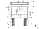
- FIG. 1 shows the structure of the component mounting machine provided with the mounting head in embodiment. It is a side view which shows the mounting head in FIG.
- the component mounting machine 10 includes a substrate transfer device 11, a component supply device 12, a component transfer device 13, a component camera 14, and a substrate camera 15, as shown in FIG.
- the substrate transfer device 11 is configured by a belt conveyor or the like.
- the substrate transport apparatus 11 sequentially transports the substrates 90 in the transport direction and positions the substrates 90 at predetermined positions in the machine. After the component mounting process by the component mounting machine 10 is completed, the board transfer device 11 carries the board 90 out of the component mounting machine 10.
- the component supply device 12 supplies components to be mounted on the substrate 90.
- the component supply device 12 includes a feeder 121 set side by side in the X-axis direction.
- the feeder 121 feeds and moves a carrier tape containing a large number of components, and supplies the components at a supply position located on the front end side of the feeder 121 so that the components can be collected.
- the component transfer device 13 transfers the component supplied by the component supply device 12 to a predetermined mounting position on the substrate 90 carried into the apparatus by the substrate transfer device 11.
- the head driving device 131 of the component transfer device 13 moves the moving table 132 in the horizontal direction (X-axis direction and Y-axis direction) by the linear motion mechanism.
- the mounting head 20 is fixed to the movable table 132 in a replaceable manner by a clamp member (not shown).
- the mounting head 20 is detachably provided with one or more holding members.
- the holding member for example, a suction nozzle that supplies negative pressure air to suck a component, a chuck that clamps the component, and the like can be used.
- the mounting head 20 supports the two suction nozzles 21 and 22 so as to be movable in the Z-axis direction and rotatable about a ⁇ axis parallel to the Z-axis.
- the detailed configuration of the mounting head 20 will be described later.
- the component camera 14 and the substrate camera 15 are digital imaging devices having an imaging device such as a CMOS.
- the component camera 14 and the board camera 15 capture an image based on the control signal and send out image data acquired by the image capture.
- the component camera 14 is fixed to the base of the component mounting machine 10 so that the optical axis is upward in the Z-axis direction.
- the component camera 14 is configured to be able to image the components held by the two suction nozzles 21 and 22 from below.
- the substrate camera 15 is configured to be able to image the substrate 90 from above.
- the component mounting machine 10 executes a mounting process for mounting components on the board 90.
- a pick-and-place cycle (hereinafter referred to as “PP cycle”) in which a component supplied by the component supply device 12 is collected and mounted at a predetermined position on the substrate 90 is referred to a plurality of times. Includes repeated processing.
- the component mounting machine 10 controls the operation of the component transfer device 13 based on information output from various sensors, a result of image processing, a control program stored in advance, and the like. Thereby, the position and angle of the two suction nozzles 21 and 22 supported by the mounting head 20 are controlled.
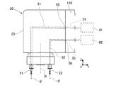
- the mounting head 20 includes two suction nozzles 21 and 22 (hereinafter referred to as “first suction nozzle 21” and “second suction nozzle 22” that suck parts by negative pressure air. ").
- the first suction nozzle 21 and the second suction nozzle 22 are detachably held on the head body 23.
- the head main body 23 is detachably clamped to the movable table 132.
- a first air passage 31 and a second air passage 32 are formed in the head body 23.
- the first air passage 31 communicates with the first supply passage 51 provided in the moving base 132 in a state where the head body 23 is attached to the moving base 132. More specifically, the first air passage 31 is connected to the first supply passage 51 at the first connection portion 55 when the head main body 23 is clamped with respect to the moving table 132. Thereby, the first air passage 31 causes the negative pressure air supplied through the first supply passage 51 to flow to the first suction nozzle 21.
- the second air passage 32 communicates with the second supply passage 52 provided in the moving base 132 in a state where the head main body 23 is attached to the moving base 132. More specifically, the second air passage 32 is connected to the second supply passage 52 at the second connection portion 56 when the head main body 23 is clamped with respect to the moving table 132. Thereby, the second air passage 32 causes the negative pressure air supplied through the second supply passage 52 to flow through the second suction nozzle 22.
- the first air passage 31 and the second air passage 32 are not communicated with each other inside the head main body 23 and are in an independent state.
- the first air passage 31 and the second air passage 32 constitute different negative pressure air supply systems.
- the configuration of the plurality of supply systems is not limited to a mode in which a plurality of air supply sources are provided (see FIGS. 2 and 3), and various modes can be adopted. Details of the negative pressure air supply system will be described later.
- the component mounting machine 10 includes one or a plurality of air supply sources.
- FIG. 2 illustrates an aspect in which the component mounting machine 10 includes two air supply sources (hereinafter, referred to as “first air supply source 81” and “second air supply source 82”).
- the first air supply source 81 and the second air supply source 82 supply negative pressure air in the same or different supply systems.
- the 1st air supply source 81 and the 2nd air supply source 82 are comprised by the air pump etc. which were provided in the inside of the component mounting machine 10, or the exterior of a machine, for example.
- the first negative pressure valve 41 is provided in the first air passage 31 as shown in FIG.
- the first negative pressure valve 41 switches between a negative pressure air flow state and a cutoff state.
- the first negative pressure valve 41 is a 3-port 2-position solenoid valve.
- the first negative pressure valve 41 is opened when the solenoid is excited by power supply, and allows negative pressure air to flow through the first air passage 31.
- the first suction nozzle 21 is supplied with the negative pressure air and can hold the component.
- one of the three ports of the first negative pressure valve 41 is always in communication with the atmosphere.
- the first negative pressure valve 41 is closed by the elastic force of the elastic member, and opens the first air passage 31 to the atmosphere.
- the first suction nozzle 21 is at atmospheric pressure and opens a part.
- a second negative pressure valve 42 is provided in the second air passage 32. Since the second negative pressure valve 42 has substantially the same configuration as the first negative pressure valve 41, a detailed description thereof will be omitted.
- the mounting head 20 controls the operations of the first negative pressure valve 41 and the second negative pressure valve 42 in accordance with a command input from the control device of the component mounting machine 10.
- the component mounting machine 10 including the mounting head 20 having the above configuration causes the first suction nozzle 21 and the second suction nozzle 22 to sequentially suck the components in the PP cycle of the mounting process. Thereafter, the components are sequentially mounted at predetermined mounting positions on the substrate 90. In such a PP cycle, a suction error in which the suction nozzle cannot normally suction the component may occur due to mechanical factors or changes in the mounting environment.
- a leak of negative pressure air generated by one suction nozzle may cause a decrease in suction power of other suction nozzles.
- a decrease in the suction force at the suction nozzle can be a factor such as a positional deviation of the component with respect to the suction nozzle.
- the mounting head 20 of the present embodiment has a negative pressure so that when one of the first suction nozzle 21 and the second suction nozzle 22 leaks negative pressure air, the other suction force is sufficiently secured.
- the air supply circuit of the mounting head 20 includes one or a plurality of supply systems.
- the first air passage 31 and the second air passage 32 in the first aspect are different air supply sources (first air supply source 81 and second air supply source 82). Are connected to each other to form different negative pressure air supply systems.
- the first air passage 31 is connected to the first supply passage 51 provided in the moving table 132 at the first connecting portion 55 when the mounting head 20 is attached to the moving table 132.
- the second air passage 32 is connected to the second supply passage 52 provided in the moving table 132 at the second connecting portion 56 when the mounting head 20 is attached to the moving table 132.
- the first supply system Cs1 includes the first suction nozzle 21, the first air passage 31, the first negative pressure valve 41, the first supply passage 51, and the first air supply source 81.
- the second supply system Cs ⁇ b> 2 includes the second suction nozzle 22, the second air passage 32, the second negative pressure valve 42, the second supply passage 52, and the second air supply source 82.
- the first supply system Cs1 and the second supply system Cs2 are in a completely independent state, and on the other hand, even if a negative pressure air leak occurs, the other is not affected.
- the first air passage 31 and the second air passage 32 in the second aspect are respectively connected to the same first air supply source 81 as shown in FIG.
- the first air passage 31 is connected to the first supply passage 51 provided in the moving table 132 at the first connecting portion 55 when the mounting head 20 is attached to the moving table 132.
- the second air passage 32 is connected to the second supply passage 52 provided in the moving table 132 at the second connecting portion 56 when the mounting head 20 is attached to the moving table 132.
- the first supply passage 51 and the second supply passage 52 communicate with each other outside the head main body 23, for example, inside the movable table 132.
- the first supply passage 51 and the second supply passage 52 are connected to the same first air supply source 81. Thereby, negative pressure air is supplied to the first air passage 31 and the second air passage 32 by the first air supply source 81 via the first supply passage 51 and the second supply passage 52.
- the first air passage 31 and the second air passage 32 of the second aspect are the total volume of the first air passage 31, the second air passage 32, the first supply passage 51, and the second supply passage 52 together. Are ensured to be equal to or higher than a predetermined value, thereby forming different negative pressure air supply systems.
- the cross-sectional area of the first air passage 31 needs to be increased over a predetermined length. The same applies to the second air passage 32, the first supply passage 51, and the second supply passage 52.
- the pressure accumulation chamber Sn is provided in the second supply passage 52.
- the total volume of the first air passage 31, the second air passage 32, the first supply passage 51, and the second supply passage 52 that are in communication with each other is secured to a predetermined value or more.
- the effect of the negative pressure air flow state on one side on the other side of the negative pressure air flow state is sufficiently reduced by the action of the pressure accumulation chamber Sn. .
- a plurality of supply systems sharing the pressure accumulating chamber Sn are configured.
- the first supply system Cs1 includes the first suction nozzle 21, the first air passage 31, the first negative pressure valve 41, the pressure accumulation chamber Sn, the first supply passage 51, and the first air supply source 81. Is done.
- the second supply system Cs2 includes a second suction nozzle 22, a second air passage 32, a second negative pressure valve 42, a pressure accumulation chamber Sn, a first supply passage 51, a second supply passage 52, and a first air supply source 81. Composed. As described above, the first supply system Cs1 and the second supply system Cs2 are in an independent state, and on the other hand, even if a negative pressure air leak occurs, the other is not affected.
- the first air passage 31 and the second air passage 32 form different supply systems by ensuring the entire volume to be equal to or greater than a predetermined value. Therefore, the pressure accumulating chamber Sn can be appropriately disposed between the first negative pressure valve 41 and the first air supply source 81 and between the second negative pressure valve 42 and the first air supply source 81. Therefore, for example, the pressure accumulation chamber Sn may be arranged in the first air passage 31 inside the head body 23.
- the first air passage 31 and the second air passage 32 do not communicate with each other inside the head main body 23 and are connected to the first supply passage 51 or the second supply passage 52, respectively.
- the entire volume can be easily ensured. That is, when the entire volume is secured to a predetermined value or more, a plurality of supply systems can be configured even if the accumulator chamber Sn is omitted as described above.
- the mounting head 20 in a 3rd aspect is the same as the state which comprises the supply system of the negative pressure air from which the 1st air path 31 and the 2nd air path 32 mutually differ, as shown to FIG. 5A.
- the valve device 24 which switches the state which comprises the supply system is provided.
- the valve device 24 is, for example, a 2-port 2-position solenoid valve.
- the mounting head 20 in the third aspect includes two air supply sources (a first air supply source 81 and a second air supply source 82), a first communication passage 61, a second communication passage 62, and a first detection sensor 71. And a second detection sensor 72.
- the first air passage 31 is formed in the head body 23 and is connected to the first supply passage 51 at the first connection portion 55.
- the first air passage 31 is connected to the first air supply source 81 through the first supply passage 51.
- the second air passage 32 is formed in the head body 23 and is connected to the second supply passage 52 at the second connection portion 56.
- the second air passage 32 is connected to the second air supply source 82 via the second supply passage 52.
- the first communication passage 61 connects the valve device 24 and the first air supply source 81 through the first air passage 31 and the first supply passage 51 to distribute negative pressure air.
- the second communication passage 62 connects the valve device 24 and the second air supply source 82 via the second air passage 32 and the second supply passage 52 to distribute negative pressure air.
- the first detection sensor 71 is provided in the first air passage 31.
- the second detection sensor 72 is provided in the second air passage 32.
- the 1st detection sensor 71 and the 2nd detection sensor 72 detect the fluctuation
- a pressure sensor that can detect the air pressure of the first air passage 31 as a flow state of negative pressure air, or a flow that can detect the air flow rate of the first air passage 31 as a flow state of negative pressure air.
- a sensor may be employed.
- a pressure sensor or a flow sensor can be employed for the second detection sensor 72.
- the mounting head 20 determines whether or not negative pressure air leaks in the first suction nozzle 21 and the second suction nozzle 22 based on the detection results of the first detection sensor 71 and the second detection sensor 72. .
- the first air passage 31 and the second air passage 32 constitute the same supply system CsU by communicating the first communication passage 61 and the second communication passage 62.
- the supply system CsU includes a first suction nozzle 21, a second suction nozzle 22, a valve device 24, a first air passage 31, a second air passage 32, a first negative pressure valve 41, a second negative pressure valve 42, and a first supply.
- the passage 51, the second supply passage 52, the first communication passage 61, the second communication passage 62, the first air supply source 81, and the second air supply source 82 are configured.
- the mounting head 20 operates the valve device 24 when it is determined that a negative pressure air leak has occurred based on the detection results of the first detection sensor 71 and the second detection sensor 72. Thereby, as shown in FIG. 5B, the valve device 24 is in a state where the first air passage 31 and the second air passage 32 constitute different supply systems by blocking the first communication passage 61 and the second communication passage 62. Switch so that
- the first supply system Cs1 includes the first suction nozzle 21, the first air passage 31, the first negative pressure valve 41, the first supply passage 51, and the first air supply source 81.
- the second supply system Cs ⁇ b> 2 includes the second suction nozzle 22, the second air passage 32, the second negative pressure valve 42, the second supply passage 52, and the second air supply source 82.
- the first supply system Cs1 and the second supply system Cs2 are in a completely independent state, and on the other hand, even if a negative pressure air leak occurs, the other is not affected.
- the first suction nozzle 21 and the second suction nozzle 22 include the first air supply source 81 and the second air supply. Negative pressure air is supplied from both sources 82.
- the mounting head 20 may suspend the first air supply source 81 or the second air supply source 82 in a state where the leakage of negative pressure air does not occur (normal state).
- the mounting head 20 suspends, for example, the second air supply source 82 in a normal state, and supplies negative pressure air to the first suction nozzle 21 and the second suction nozzle 22 by the first air supply source 81.
- a check valve (not shown) is provided between the valve device 24 and the second air supply source 82, for example, in the second supply passage 52, and negative pressure air flows to the second air supply source 82 side. Is prevented.
- the mounting head 20 operates the second air supply source 82 when it is determined that a negative pressure air leak has occurred based on the detection results of the first detection sensor 71 and the second detection sensor 72. Make sure that negative pressure air can be supplied. Thereafter, the mounting head 20 operates the valve device 24. Thereby, as shown in FIG. 5B, the valve device 24 blocks the first communication passage 61 and the second communication passage 62 so that the first air passage 31 and the second air passage 32 are different from each other (first supply). It is assumed that the system Cs1 and the second supply system Cs2) are configured.
- the mounting head 20 configures one supply system CsU by communicating the first communication passage 61 and the second communication passage 62 in a normal state.
- the operation of the first air supply source 81 and the second air supply source 82 stabilizes the supply of negative pressure air in the supply system CsU, and the operation load is reduced by stopping one of them. Mitigating.
- the first air supply source 81 and the second air supply source 82 may be arranged inside the mounting head 20.
- the mounting head 20 includes the first suction nozzle 21 and the second suction nozzle 22 that suck parts by negative pressure air, and the parts mounting.
- the head main body 23 that is detachably attached to the moving base 132 of the machine 10 and holds the first suction nozzle 21 and the second suction nozzle 22, and the head main body 23 in the state where the head main body 23 is attached to the moving base 132.
- a first air passage 31 that communicates with a first supply passage 51 provided in a moving table 132 and distributes negative pressure air supplied through the first supply passage 51 to the first suction nozzle 21, and the head
- the main body 23 communicates with the second supply passage 52 provided in the movable table 132, and is supplied via the second supply passage 52.
- a second air passage 32 through which the negative pressure air to be supplied flows to the second suction nozzle 22.
- the first air passage 31 that distributes the negative pressure air to the first suction nozzle 21 and the second air passage 32 that distributes the negative pressure air to the second suction nozzle 22 are the head body. 23 are independent from each other. That is, the first air passage 31 and the second air passage 32 do not communicate with each other inside the head main body 23 and are separately connected at the boundary between the head main body 23 and the moving base 132. As a result, the first air passage 31 and the second air passage 32 constitute at least the negative pressure air supply systems (the first supply system Cs1 and the second supply system Cs2) that are different from each other inside the head body 23.
- the mounting head 20 is a head that holds the first suction nozzle 21 and the second suction nozzle 22 that suck parts by negative pressure air, and the first suction nozzle 21 and the second suction nozzle 22.
- a main body 23 a first air passage 31 through which the supplied negative pressure air flows to the first suction nozzle 21, a second air passage 32 through which the supplied negative pressure air flows to the second suction nozzle 22, A state in which the first air passage 31 and the second air passage 32 form the same supply system CsU as the state in which the negative air supply systems (the first supply system Cs1 and the second supply system Cs2) are different from each other.
- a valve device 24 for switching between the two.
- the state which comprises the supply system (the 1st supply system Cs1, the 2nd supply system Cs2) of the negative pressure air which changes with valve apparatuses 24, and the state which comprises the same supply system CsU are switched. Therefore, when a negative pressure air leak occurs in one suction nozzle, the separate first supply system Cs1 and second supply system Cs2 are configured to affect the suction force in the other suction nozzle. Can be reduced. As a result, it is possible to maintain the accuracy of the mounting process.
- the mounting head 20 includes two suction nozzles (first suction nozzle 21 and second suction nozzle 22).
- the mounting head 20 may be configured to include three or more suction nozzles.
- a plurality of air passages that supply negative pressure to three or more suction nozzles may be connected to the same number of supply passages provided in the movable table 132 on a one-to-one basis.
- a negative pressure air supply system is configured for each of three or more air passages or for each of a plurality of groups.
- the plurality of supply passages are in one-to-one correspondence with the same number of air supply sources as the suction nozzles, for example, as in the first and third aspects of the air supply circuit. It is good also as a structure connected by.
- the number and volume of the pressure accumulating chambers Sn are appropriately set based on the number of suction nozzles and the number of groups, for example, as in the second aspect of the air supply circuit. May be. Even in such a configuration, the same effects as in the embodiment can be obtained.
Abstract
This mounting head comprises: a first suction nozzle and a second suction nozzle which suck a component using negative pressure air; a head body which is removably attached to a movable platform of a component mounter, and holds the first suction nozzle and the second suction nozzle; a first air passage which, when the head body is attached to the movable platform, connects to a first supply passage provided to the movable platform, and circulates negative pressure air supplied via the first supply passage to the first suction nozzle; and a second air passage which, when the head body is attached to the movable platform, connects to a second supply passage provided to the movable platform, and circulates negative pressure air supplied via the second supply passage to the second suction nozzle.
Description
本発明は、装着ヘッドに関するものである。
The present invention relates to a mounting head.
装着ヘッドは、回路基板に部品を装着する部品装着機を構成し、部品装着機による装着処理に用いられる。装着ヘッドは、負圧エアにより部品を吸着する吸着ノズルを複数保持する。特許文献1には、12個の吸着ノズルを着脱可能に保持する装着ヘッドが開示されている。この装着ヘッドは、ヘッド本体の内部においてエア通路を分岐させて、装着ヘッドの外部に設けられたエア供給源から供給された負圧エアを12個の吸着ノズルに分配するように構成されている。
The mounting head constitutes a component mounting machine that mounts components on a circuit board and is used for mounting processing by the component mounting machine. The mounting head holds a plurality of suction nozzles that suck parts by negative pressure air. Patent Document 1 discloses a mounting head that detachably holds twelve suction nozzles. The mounting head is configured to branch an air passage inside the head body and distribute negative pressure air supplied from an air supply source provided outside the mounting head to twelve suction nozzles. .
上記のような装着ヘッドを用いた装着処理において、例えば複数の吸着ノズルの一つが部品の吸着をミスした場合に、負圧エアのリークが発生する。負圧エアのリークが他の吸着ノズルにおける吸着力に影響すると、部品を吸着した状態で移動した際に吸着ノズルに対する部品の位置ずれが発生し、装着処理の精度低下の要因となり得る。
In the mounting process using the mounting head as described above, for example, when one of the plurality of suction nozzles misses suction of a component, a negative pressure air leak occurs. If the negative pressure air leak affects the suction force of the other suction nozzles, the parts may be displaced with respect to the suction nozzles when moved while the parts are sucked, which may cause a reduction in the accuracy of the mounting process.
本明細書は、負圧エアのリークが発生した場合に他の吸着ノズルにおける吸着力への影響を低減し、装着処理の精度維持を図ることができる装着ヘッドを提供することを目的とする。
It is an object of the present specification to provide a mounting head that can reduce the influence on the suction force of other suction nozzles when negative pressure air leaks and can maintain the precision of the mounting process.
本明細書は、負圧エアにより部品を吸着する第一吸着ノズルおよび第二吸着ノズルと、部品装着機の移動台に着脱可能に取り付けられ、前記第一吸着ノズルおよび前記第二吸着ノズルを保持するヘッド本体と、前記ヘッド本体が前記移動台に取り付けられた状態において前記移動台に設けられた第一供給通路と連通し、前記第一供給通路を介して供給される負圧エアを前記第一吸着ノズルに流通させる第一エア通路と、前記ヘッド本体が前記移動台に取り付けられた状態において前記移動台に設けられた第二供給通路と連通し、前記第二供給通路を介して供給される負圧エアを前記第二吸着ノズルに流通させる第二エア通路と、を備える第一の装着ヘッドを開示する。
The present specification includes a first suction nozzle and a second suction nozzle that suck parts by negative pressure air, and a detachable attachment to a moving table of a component mounting machine, and holds the first suction nozzle and the second suction nozzle. And a negative pressure air supplied through the first supply passage is communicated with the first supply passage provided in the movable base in a state where the head main body is attached to the movable base. A first air passage that circulates to one suction nozzle, and a second supply passage provided in the moving base in a state where the head body is attached to the moving base, are supplied via the second supply passage. And a second air passage for circulating negative pressure air to the second suction nozzle.
本明細書は、負圧エアにより部品を吸着する第一吸着ノズルおよび第二吸着ノズルと、前記第一吸着ノズルおよび前記第二吸着ノズルを保持するヘッド本体と、供給される負圧エアを前記第一吸着ノズルに流通させる第一エア通路と、供給される負圧エアを前記第二吸着ノズルに流通させる第二エア通路と、前記第一エア通路と前記第二エア通路とが互いに異なる負圧エアの供給系統を構成する状態と同一の供給系統を構成する状態とを切り換えるバルブ装置と、を備える第二の装着ヘッドを開示する。
The present specification includes a first suction nozzle and a second suction nozzle that suck parts by negative pressure air, a head body that holds the first suction nozzle and the second suction nozzle, and the negative pressure air that is supplied The first air passage that circulates to the first suction nozzle, the second air passage that circulates the negative pressure air supplied to the second suction nozzle, and the first air passage and the second air passage are different from each other. A second mounting head is disclosed that includes a valve device that switches between a state that constitutes a pressurized air supply system and a state that constitutes the same supply system.
第一の装着ヘッドの構成によると、第一吸着ノズルへの負圧エアを流通させる第一エア通路、および第二吸着ノズルへの負圧エアを流通させる第二エア通路は、ヘッド本体の内部において互いに独立している。つまり、第一エア通路および第二エア通路は、ヘッド本体の内部において連通しておらず、移動台とヘッド本体との境界部において別々に連結される。これにより、第一エア通路および第二エア通路は、ヘッド本体の内部において互いに異なる負圧エアの供給系統を構成する。よって、一の吸着ノズルにおいて負圧エアのリークが発生した場合に、他の吸着ノズルにおける吸着力への影響を低減できる。結果として、装着処理の精度維持を図ることができる。
According to the configuration of the first mounting head, the first air passage for flowing negative pressure air to the first suction nozzle and the second air passage for flowing negative pressure air to the second suction nozzle are arranged inside the head body. Are independent of each other. That is, the first air passage and the second air passage are not communicated with each other inside the head main body, and are separately connected at the boundary portion between the moving base and the head main body. Thus, the first air passage and the second air passage constitute different negative pressure air supply systems inside the head body. Therefore, when negative pressure air leaks in one suction nozzle, the influence on the suction force in the other suction nozzles can be reduced. As a result, it is possible to maintain the accuracy of the mounting process.
第二の装着ヘッドの構成によると、第一吸着ノズルへの負圧エアを流通させる第一エア通路、および第二吸着ノズルへの負圧エアを流通させる第二エア通路は、バルブ装置によって異なる負圧エアの供給系統を構成する状態と、同一の供給系統を構成する状態とを切り換えられる。よって、一の吸着ノズルにおいて負圧エアのリークが発生した場合に、異なる供給系統が構成されることにより、他の吸着ノズルにおける吸着力への影響を低減できる。結果として、装着処理の精度維持を図ることができる。
According to the configuration of the second mounting head, the first air passage for flowing negative pressure air to the first suction nozzle and the second air passage for flowing negative pressure air to the second suction nozzle differ depending on the valve device. The state constituting the negative pressure air supply system and the state constituting the same supply system can be switched. Therefore, when negative pressure air leaks in one suction nozzle, the influence on the suction force in the other suction nozzles can be reduced by configuring different supply systems. As a result, it is possible to maintain the accuracy of the mounting process.
1.部品装着機10の構成
部品装着機10は、図1に示すように、基板搬送装置11、部品供給装置12、部品移載装置13、部品カメラ14、および基板カメラ15を備える。基板搬送装置11は、ベルトコンベアなどにより構成される。基板搬送装置11は、基板90を搬送方向へと順次搬送するとともに、基板90を機内の所定位置に位置決めする。基板搬送装置11は、部品装着機10による部品の装着処理が終了した後に、基板90を部品装着機10の機外に搬出する。 1. Configuration ofComponent Mounting Machine 10 The component mounting machine 10 includes a substrate transfer device 11, a component supply device 12, a component transfer device 13, a component camera 14, and a substrate camera 15, as shown in FIG. The substrate transfer device 11 is configured by a belt conveyor or the like. The substrate transport apparatus 11 sequentially transports the substrates 90 in the transport direction and positions the substrates 90 at predetermined positions in the machine. After the component mounting process by the component mounting machine 10 is completed, the board transfer device 11 carries the board 90 out of the component mounting machine 10.
部品装着機10は、図1に示すように、基板搬送装置11、部品供給装置12、部品移載装置13、部品カメラ14、および基板カメラ15を備える。基板搬送装置11は、ベルトコンベアなどにより構成される。基板搬送装置11は、基板90を搬送方向へと順次搬送するとともに、基板90を機内の所定位置に位置決めする。基板搬送装置11は、部品装着機10による部品の装着処理が終了した後に、基板90を部品装着機10の機外に搬出する。 1. Configuration of
部品供給装置12は、基板90に装着される部品を供給する。部品供給装置12は、X軸方向に並んでセットされたフィーダ121を備える。フィーダ121は、多数の部品が収納されたキャリアテープを送り移動させて、フィーダ121の先端側に位置する供給位置において部品を採取可能に供給する。
The component supply device 12 supplies components to be mounted on the substrate 90. The component supply device 12 includes a feeder 121 set side by side in the X-axis direction. The feeder 121 feeds and moves a carrier tape containing a large number of components, and supplies the components at a supply position located on the front end side of the feeder 121 so that the components can be collected.
部品移載装置13は、部品供給装置12により供給された部品を、基板搬送装置11により機内に搬入された基板90上の所定の装着位置まで移載する。部品移載装置13のヘッド駆動装置131は、直動機構により移動台132を水平方向(X軸方向およびY軸方向)に移動させる。移動台132には、図示しないクランプ部材により装着ヘッド20が交換可能に固定される。
The component transfer device 13 transfers the component supplied by the component supply device 12 to a predetermined mounting position on the substrate 90 carried into the apparatus by the substrate transfer device 11. The head driving device 131 of the component transfer device 13 moves the moving table 132 in the horizontal direction (X-axis direction and Y-axis direction) by the linear motion mechanism. The mounting head 20 is fixed to the movable table 132 in a replaceable manner by a clamp member (not shown).
装着ヘッド20には、1または複数の保持部材が着脱可能に設けられる。上記の保持部材としては、例えば負圧エアを供給されて部品を吸着する吸着ノズルや、部品をクランプするチャックなどが採用され得る。本実施形態において、装着ヘッド20は、図2に示すように、2つの吸着ノズル21,22をZ軸方向に移動可能に、且つZ軸に平行なθ軸周りに回転可能に支持する。装着ヘッド20の詳細構成については後述する。
The mounting head 20 is detachably provided with one or more holding members. As the holding member, for example, a suction nozzle that supplies negative pressure air to suck a component, a chuck that clamps the component, and the like can be used. In the present embodiment, as shown in FIG. 2, the mounting head 20 supports the two suction nozzles 21 and 22 so as to be movable in the Z-axis direction and rotatable about a θ axis parallel to the Z-axis. The detailed configuration of the mounting head 20 will be described later.
部品カメラ14、および基板カメラ15は、CMOSなどの撮像素子を有するデジタル式の撮像装置である。部品カメラ14、および基板カメラ15は、制御信号に基づいて撮像を行い、当該撮像により取得した画像データを送出する。部品カメラ14は、光軸がZ軸方向の上向きとなるように部品装着機10の基台に固定されている。部品カメラ14は、2つの吸着ノズル21,22に保持された部品を下方から撮像可能に構成される。基板カメラ15は、基板90を上方から撮像可能に構成されている。
The component camera 14 and the substrate camera 15 are digital imaging devices having an imaging device such as a CMOS. The component camera 14 and the board camera 15 capture an image based on the control signal and send out image data acquired by the image capture. The component camera 14 is fixed to the base of the component mounting machine 10 so that the optical axis is upward in the Z-axis direction. The component camera 14 is configured to be able to image the components held by the two suction nozzles 21 and 22 from below. The substrate camera 15 is configured to be able to image the substrate 90 from above.
部品装着機10は、基板90に部品を装着する装着処理を実行する。上記の装着処理には、部品供給装置12により供給された部品を採取して基板90における所定位置に部品を装着するピックアンドプレースサイクル(以下、「PPサイクル」と称する)を複数回に亘って繰り返す処理が含まれる。部品装着機10は、装着処理において、各種センサから出力される情報や画像処理の結果、予め記憶された制御プログラムなどに基づき、部品移載装置13の動作を制御する。これにより、装着ヘッド20に支持された2つの吸着ノズル21,22の位置および角度が制御される。
The component mounting machine 10 executes a mounting process for mounting components on the board 90. In the mounting process described above, a pick-and-place cycle (hereinafter referred to as “PP cycle”) in which a component supplied by the component supply device 12 is collected and mounted at a predetermined position on the substrate 90 is referred to a plurality of times. Includes repeated processing. In the mounting process, the component mounting machine 10 controls the operation of the component transfer device 13 based on information output from various sensors, a result of image processing, a control program stored in advance, and the like. Thereby, the position and angle of the two suction nozzles 21 and 22 supported by the mounting head 20 are controlled.
2.装着ヘッド20の詳細構成
装着ヘッド20は、図2に示すように、負圧エアにより部品を吸着する2つの吸着ノズル21,22(以下、「第一吸着ノズル21」および「第二吸着ノズル22」と称する)を備える。第一吸着ノズル21および第二吸着ノズル22は、ヘッド本体23に着脱可能に保持される。ヘッド本体23は、移動台132に着脱可能にクランプされる。 2. Detailed Configuration ofMounting Head 20 As shown in FIG. 2, the mounting head 20 includes two suction nozzles 21 and 22 (hereinafter referred to as “first suction nozzle 21” and “second suction nozzle 22” that suck parts by negative pressure air. "). The first suction nozzle 21 and the second suction nozzle 22 are detachably held on the head body 23. The head main body 23 is detachably clamped to the movable table 132.
装着ヘッド20は、図2に示すように、負圧エアにより部品を吸着する2つの吸着ノズル21,22(以下、「第一吸着ノズル21」および「第二吸着ノズル22」と称する)を備える。第一吸着ノズル21および第二吸着ノズル22は、ヘッド本体23に着脱可能に保持される。ヘッド本体23は、移動台132に着脱可能にクランプされる。 2. Detailed Configuration of
ヘッド本体23には、第一エア通路31および第二エア通路32が形成される。第一エア通路31は、ヘッド本体23が移動台132に取り付けられた状態において移動台132に設けられた第一供給通路51と連通する。より詳細には、第一エア通路31は、ヘッド本体23が移動台132に対してクランプされると、第一接続部55において第一供給通路51に接続される。これにより、第一エア通路31は、第一供給通路51を介して供給される負圧エアを第一吸着ノズル21に流通させる。
A first air passage 31 and a second air passage 32 are formed in the head body 23. The first air passage 31 communicates with the first supply passage 51 provided in the moving base 132 in a state where the head body 23 is attached to the moving base 132. More specifically, the first air passage 31 is connected to the first supply passage 51 at the first connection portion 55 when the head main body 23 is clamped with respect to the moving table 132. Thereby, the first air passage 31 causes the negative pressure air supplied through the first supply passage 51 to flow to the first suction nozzle 21.
第二エア通路32は、ヘッド本体23が移動台132に取り付けられた状態において移動台132に設けられた第二供給通路52と連通する。より詳細には、第二エア通路32は、ヘッド本体23が移動台132に対してクランプされると、第二接続部56において第二供給通路52に接続される。これにより、第二エア通路32は、第二供給通路52を介して供給される負圧エアを第二吸着ノズル22に流通させる。
The second air passage 32 communicates with the second supply passage 52 provided in the moving base 132 in a state where the head main body 23 is attached to the moving base 132. More specifically, the second air passage 32 is connected to the second supply passage 52 at the second connection portion 56 when the head main body 23 is clamped with respect to the moving table 132. Thereby, the second air passage 32 causes the negative pressure air supplied through the second supply passage 52 to flow through the second suction nozzle 22.
第一エア通路31および第二エア通路32は、ヘッド本体23の内部において連通しておらず独立した状態とされる。換言すると、第一エア通路31および第二エア通路32は、互いに異なる負圧エアの供給系統を構成する。複数の供給系統を構成するには、エア供給源を複数にする態様(図2および図3を参照)に限られず、種々の態様を採用し得る。負圧エアの供給系統の詳細については後述する。
The first air passage 31 and the second air passage 32 are not communicated with each other inside the head main body 23 and are in an independent state. In other words, the first air passage 31 and the second air passage 32 constitute different negative pressure air supply systems. The configuration of the plurality of supply systems is not limited to a mode in which a plurality of air supply sources are provided (see FIGS. 2 and 3), and various modes can be adopted. Details of the negative pressure air supply system will be described later.
また、部品装着機10は、1または複数のエア供給源を備える。図2には、部品装着機10が2つのエア供給源(以下、「第一エア供給源81」および「第二エア供給源82」と称する)を備える態様を例示する。第一エア供給源81および第二エア供給源82は、同一または異なる供給系統において負圧エアを供給する。第一エア供給源81および第二エア供給源82は、例えば部品装着機10の機内または機外に設けられたエアポンプなどにより構成される。
The component mounting machine 10 includes one or a plurality of air supply sources. FIG. 2 illustrates an aspect in which the component mounting machine 10 includes two air supply sources (hereinafter, referred to as “first air supply source 81” and “second air supply source 82”). The first air supply source 81 and the second air supply source 82 supply negative pressure air in the same or different supply systems. The 1st air supply source 81 and the 2nd air supply source 82 are comprised by the air pump etc. which were provided in the inside of the component mounting machine 10, or the exterior of a machine, for example.
ここで、第一エア通路31には、図3に示すように、第一負圧バルブ41が設けられる。第一負圧バルブ41は、負圧エアの流通状態と遮断状態とを切り換える。第一負圧バルブ41は、本実施形態において、3ポート2位置のソレノイドバルブである。第一負圧バルブ41は、ソレノイドが給電により励磁されると開状態となり、第一エア通路31に負圧エアを流通させる。第一エア通路31が負圧エアを流通すると、第一吸着ノズル21は、負圧エアが供給されて部品を保持可能な状態となる。
Here, the first negative pressure valve 41 is provided in the first air passage 31 as shown in FIG. The first negative pressure valve 41 switches between a negative pressure air flow state and a cutoff state. In the present embodiment, the first negative pressure valve 41 is a 3-port 2-position solenoid valve. The first negative pressure valve 41 is opened when the solenoid is excited by power supply, and allows negative pressure air to flow through the first air passage 31. When the first air passage 31 circulates the negative pressure air, the first suction nozzle 21 is supplied with the negative pressure air and can hold the component.
また、第一負圧バルブ41の3ポートの一つは、大気に常時連通している。第一負圧バルブ41は、ソレノイドへの給電が遮断されると弾性部材の弾性力により閉状態となり、第一エア通路31を大気に開放する。第一エア通路31が大気に開放されると、第一吸着ノズル21は、大気圧となり部品を開放する状態となる。
Also, one of the three ports of the first negative pressure valve 41 is always in communication with the atmosphere. When the power supply to the solenoid is interrupted, the first negative pressure valve 41 is closed by the elastic force of the elastic member, and opens the first air passage 31 to the atmosphere. When the first air passage 31 is opened to the atmosphere, the first suction nozzle 21 is at atmospheric pressure and opens a part.
同様に、第二エア通路32には、第二負圧バルブ42が設けられる。第二負圧バルブ42は、第一負圧バルブ41と実質的に同様の構成であるため詳細な説明を省略する。装着ヘッド20は、部品装着機10の制御装置から入力する指令に応じて、第一負圧バルブ41、および第二負圧バルブ42の動作を制御する。
Similarly, a second negative pressure valve 42 is provided in the second air passage 32. Since the second negative pressure valve 42 has substantially the same configuration as the first negative pressure valve 41, a detailed description thereof will be omitted. The mounting head 20 controls the operations of the first negative pressure valve 41 and the second negative pressure valve 42 in accordance with a command input from the control device of the component mounting machine 10.
3.負圧エアの供給系統の構成
上記のような構成からなる装着ヘッド20を備える部品装着機10は、装着処理のPPサイクルにおいて、第一吸着ノズル21および第二吸着ノズル22に部品を順次吸着させた後に、基板90の所定の装着位置に部品を順次装着する。このようなPPサイクルでは、機械的な要因や装着環境の変動などに起因して、吸着ノズルが部品を正常に吸着できない吸着ミスが発生し得る。 3. Configuration of Negative Pressure Air Supply System Thecomponent mounting machine 10 including the mounting head 20 having the above configuration causes the first suction nozzle 21 and the second suction nozzle 22 to sequentially suck the components in the PP cycle of the mounting process. Thereafter, the components are sequentially mounted at predetermined mounting positions on the substrate 90. In such a PP cycle, a suction error in which the suction nozzle cannot normally suction the component may occur due to mechanical factors or changes in the mounting environment.
上記のような構成からなる装着ヘッド20を備える部品装着機10は、装着処理のPPサイクルにおいて、第一吸着ノズル21および第二吸着ノズル22に部品を順次吸着させた後に、基板90の所定の装着位置に部品を順次装着する。このようなPPサイクルでは、機械的な要因や装着環境の変動などに起因して、吸着ノズルが部品を正常に吸着できない吸着ミスが発生し得る。 3. Configuration of Negative Pressure Air Supply System The
上記のような吸着ミスが発生すると、吸着ノズルから負圧エアがリークして、吸着ノズルからエア供給源までのエア通路の空気圧が上昇する。このとき、装着ヘッドが複数の吸着ノズルを備える構成では、一つの吸着ノズルで発生した負圧エアのリークが他の吸着ノズルの吸着力の低下を招来するおそれがある。吸着ノズルにおける吸着力の低下は、吸着ノズルに対する部品の位置ずれなどの要因となり得る。
When such a suction mistake occurs, negative pressure air leaks from the suction nozzle, and the air pressure in the air passage from the suction nozzle to the air supply source increases. At this time, in the configuration in which the mounting head includes a plurality of suction nozzles, a leak of negative pressure air generated by one suction nozzle may cause a decrease in suction power of other suction nozzles. A decrease in the suction force at the suction nozzle can be a factor such as a positional deviation of the component with respect to the suction nozzle.
そこで、本実施形態の装着ヘッド20は、第一吸着ノズル21および第二吸着ノズル22の一方に負圧エアのリークが発生した場合に、他方の吸着力が十分に確保されるように負圧エアの供給系統を複数構成する。以下では、装着ヘッド20に構成されるエア供給回路の各態様について説明する。装着ヘッド20のエア供給回路には、1または複数の供給系統が含まれる。
Therefore, the mounting head 20 of the present embodiment has a negative pressure so that when one of the first suction nozzle 21 and the second suction nozzle 22 leaks negative pressure air, the other suction force is sufficiently secured. Configure multiple air supply systems. Below, each aspect of the air supply circuit comprised in the mounting head 20 is demonstrated. The air supply circuit of the mounting head 20 includes one or a plurality of supply systems.
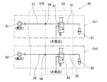
3-1.エア供給回路の第一態様
第一態様における第一エア通路31および第二エア通路32は、図3に示すように、異なるエア供給源(第一エア供給源81および第二エア供給源82)にそれぞれ連結されることにより互いに異なる負圧エアの供給系統を構成する。第一エア通路31は、装着ヘッド20が移動台132に取り付けられた際に、移動台132に設けられた第一供給通路51に第一接続部55において接続される。同様に、第二エア通路32は、装着ヘッド20が移動台132に取り付けられた際に、移動台132に設けられた第二供給通路52に第二接続部56において接続される。 3-1. First Aspect of Air Supply Circuit As shown in FIG. 3, thefirst air passage 31 and the second air passage 32 in the first aspect are different air supply sources (first air supply source 81 and second air supply source 82). Are connected to each other to form different negative pressure air supply systems. The first air passage 31 is connected to the first supply passage 51 provided in the moving table 132 at the first connecting portion 55 when the mounting head 20 is attached to the moving table 132. Similarly, the second air passage 32 is connected to the second supply passage 52 provided in the moving table 132 at the second connecting portion 56 when the mounting head 20 is attached to the moving table 132.
第一態様における第一エア通路31および第二エア通路32は、図3に示すように、異なるエア供給源(第一エア供給源81および第二エア供給源82)にそれぞれ連結されることにより互いに異なる負圧エアの供給系統を構成する。第一エア通路31は、装着ヘッド20が移動台132に取り付けられた際に、移動台132に設けられた第一供給通路51に第一接続部55において接続される。同様に、第二エア通路32は、装着ヘッド20が移動台132に取り付けられた際に、移動台132に設けられた第二供給通路52に第二接続部56において接続される。 3-1. First Aspect of Air Supply Circuit As shown in FIG. 3, the
第一態様において、第一供給系統Cs1は、第一吸着ノズル21、第一エア通路31、第一負圧バルブ41、第一供給通路51、および第一エア供給源81により構成される。第二供給系統Cs2は、第二吸着ノズル22、第二エア通路32、第二負圧バルブ42、第二供給通路52、および第二エア供給源82により構成される。上記のように第一供給系統Cs1および第二供給系統Cs2は、完全に独立した状態にあり、一方で負圧エアのリークが発生しても他方に影響しない構成となっている。
In the first aspect, the first supply system Cs1 includes the first suction nozzle 21, the first air passage 31, the first negative pressure valve 41, the first supply passage 51, and the first air supply source 81. The second supply system Cs <b> 2 includes the second suction nozzle 22, the second air passage 32, the second negative pressure valve 42, the second supply passage 52, and the second air supply source 82. As described above, the first supply system Cs1 and the second supply system Cs2 are in a completely independent state, and on the other hand, even if a negative pressure air leak occurs, the other is not affected.
3-2.エア供給回路の第二態様
第二態様における第一エア通路31および第二エア通路32は、図4に示すように、同一の第一エア供給源81にそれぞれ連結される。また、第一エア通路31は、装着ヘッド20が移動台132に取り付けられた際に、移動台132に設けられた第一供給通路51に第一接続部55において接続される。同様に、第二エア通路32は、装着ヘッド20が移動台132に取り付けられた際に、移動台132に設けられた第二供給通路52に第二接続部56において接続される。 3-2. Second Aspect of Air Supply Circuit Thefirst air passage 31 and the second air passage 32 in the second aspect are respectively connected to the same first air supply source 81 as shown in FIG. The first air passage 31 is connected to the first supply passage 51 provided in the moving table 132 at the first connecting portion 55 when the mounting head 20 is attached to the moving table 132. Similarly, the second air passage 32 is connected to the second supply passage 52 provided in the moving table 132 at the second connecting portion 56 when the mounting head 20 is attached to the moving table 132.
第二態様における第一エア通路31および第二エア通路32は、図4に示すように、同一の第一エア供給源81にそれぞれ連結される。また、第一エア通路31は、装着ヘッド20が移動台132に取り付けられた際に、移動台132に設けられた第一供給通路51に第一接続部55において接続される。同様に、第二エア通路32は、装着ヘッド20が移動台132に取り付けられた際に、移動台132に設けられた第二供給通路52に第二接続部56において接続される。 3-2. Second Aspect of Air Supply Circuit The
第一供給通路51および第二供給通路52は、ヘッド本体23の外部であって、例えば移動台132の内部において連通する。また、第一供給通路51および第二供給通路52は、同一の第一エア供給源81に連結される。これにより、第一エア通路31および第二エア通路32には、第一供給通路51および第二供給通路52を介して、第一エア供給源81により負圧エアが供給される。
The first supply passage 51 and the second supply passage 52 communicate with each other outside the head main body 23, for example, inside the movable table 132. The first supply passage 51 and the second supply passage 52 are connected to the same first air supply source 81. Thereby, negative pressure air is supplied to the first air passage 31 and the second air passage 32 by the first air supply source 81 via the first supply passage 51 and the second supply passage 52.
ここで、第二態様の第一エア通路31および第二エア通路32は、第一エア通路31、第二エア通路32、第一供給通路51、および第二供給通路52を併せた全体の容積が所定値以上に確保されることにより互いに異なる負圧エアの供給系統を構成する。ここで、上記の全体の容積を所定値以上に確保するには、例えば第一エア通路31の断面積を所定長さに亘って大きく形成する必要がある。これは、第二エア通路32、第一供給通路51、および第二供給通路52についても同様である。
Here, the first air passage 31 and the second air passage 32 of the second aspect are the total volume of the first air passage 31, the second air passage 32, the first supply passage 51, and the second supply passage 52 together. Are ensured to be equal to or higher than a predetermined value, thereby forming different negative pressure air supply systems. Here, in order to ensure the above-described overall volume to be equal to or greater than a predetermined value, for example, the cross-sectional area of the first air passage 31 needs to be increased over a predetermined length. The same applies to the second air passage 32, the first supply passage 51, and the second supply passage 52.
第二態様では、第二供給通路52に蓄圧室Snが設けられる。これにより、互いに連通する第一エア通路31、第二エア通路32、第一供給通路51、および第二供給通路52を併せた全体の容積を所定値以上に確保している。このように、全体の容積が所定値以上に確保されると、蓄圧室Snの作用によって一方における負圧エアの流通状態の変動が他方における負圧エアの流通状態に与える影響が十分に小さくなる。結果として、蓄圧室Snが共用される複数の供給系統が構成される。
In the second mode, the pressure accumulation chamber Sn is provided in the second supply passage 52. As a result, the total volume of the first air passage 31, the second air passage 32, the first supply passage 51, and the second supply passage 52 that are in communication with each other is secured to a predetermined value or more. In this way, when the entire volume is secured to a predetermined value or more, the effect of the negative pressure air flow state on one side on the other side of the negative pressure air flow state is sufficiently reduced by the action of the pressure accumulation chamber Sn. . As a result, a plurality of supply systems sharing the pressure accumulating chamber Sn are configured.
具体的には、第一供給系統Cs1は、第一吸着ノズル21、第一エア通路31、第一負圧バルブ41、蓄圧室Sn、第一供給通路51、および第一エア供給源81により構成される。第二供給系統Cs2は、第二吸着ノズル22、第二エア通路32、第二負圧バルブ42、蓄圧室Sn、第一供給通路51、第二供給通路52、および第一エア供給源81により構成される。上記のように第一供給系統Cs1および第二供給系統Cs2は、互いに独立した状態にあり、一方で負圧エアのリークが発生しても他方に影響しない構成となっている。
Specifically, the first supply system Cs1 includes the first suction nozzle 21, the first air passage 31, the first negative pressure valve 41, the pressure accumulation chamber Sn, the first supply passage 51, and the first air supply source 81. Is done. The second supply system Cs2 includes a second suction nozzle 22, a second air passage 32, a second negative pressure valve 42, a pressure accumulation chamber Sn, a first supply passage 51, a second supply passage 52, and a first air supply source 81. Composed. As described above, the first supply system Cs1 and the second supply system Cs2 are in an independent state, and on the other hand, even if a negative pressure air leak occurs, the other is not affected.
なお、上記のように全体の容積が所定値以上に確保されることにより、第一エア通路31および第二エア通路32が異なる供給系統を構成する。そのため、蓄圧室Snは、第一負圧バルブ41から第一エア供給源81までの間、第二負圧バルブ42から第一エア供給源81までの間であれば適宜配置することができる。よって、例えばヘッド本体23の内部における第一エア通路31に蓄圧室Snが配置される構成としてもよい。
Note that, as described above, the first air passage 31 and the second air passage 32 form different supply systems by ensuring the entire volume to be equal to or greater than a predetermined value. Therefore, the pressure accumulating chamber Sn can be appropriately disposed between the first negative pressure valve 41 and the first air supply source 81 and between the second negative pressure valve 42 and the first air supply source 81. Therefore, for example, the pressure accumulation chamber Sn may be arranged in the first air passage 31 inside the head body 23.
また、本実施形態のように、第一エア通路31および第二エア通路32がヘッド本体23の内部において連通せず、それぞれが第一供給通路51または第二供給通路52に接続される構成は、従来のようにヘッド本体23の内部で連通する構成と比較して全体の容積を確保しやすい。つまり、全体の容積が所定値以上に確保されている場合には、上記のように蓄圧室Snを省略しても複数の供給系統を構成することができる。
Further, as in the present embodiment, the first air passage 31 and the second air passage 32 do not communicate with each other inside the head main body 23 and are connected to the first supply passage 51 or the second supply passage 52, respectively. Compared to the conventional configuration in which communication is performed inside the head main body 23, the entire volume can be easily ensured. That is, when the entire volume is secured to a predetermined value or more, a plurality of supply systems can be configured even if the accumulator chamber Sn is omitted as described above.
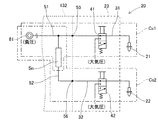
3-3.エア供給回路の第三態様
第三態様における装着ヘッド20は、図5Aに示すように、第一エア通路31と第二エア通路32とが互いに異なる負圧エアの供給系統を構成する状態と同一の供給系統を構成する状態とを切り換えるバルブ装置24を備える。バルブ装置24は、例えば2ポート2位置のソレノイドバルブである。 3-3. 3rd aspect of an air supply circuit The mountinghead 20 in a 3rd aspect is the same as the state which comprises the supply system of the negative pressure air from which the 1st air path 31 and the 2nd air path 32 mutually differ, as shown to FIG. 5A. The valve device 24 which switches the state which comprises the supply system is provided. The valve device 24 is, for example, a 2-port 2-position solenoid valve.
第三態様における装着ヘッド20は、図5Aに示すように、第一エア通路31と第二エア通路32とが互いに異なる負圧エアの供給系統を構成する状態と同一の供給系統を構成する状態とを切り換えるバルブ装置24を備える。バルブ装置24は、例えば2ポート2位置のソレノイドバルブである。 3-3. 3rd aspect of an air supply circuit The mounting
第三態様における装着ヘッド20は、2つのエア供給源(第一エア供給源81、第二エア供給源82)と、第一連絡通路61と、第二連絡通路62と、第一検出センサ71と、第二検出センサ72とを備える。第一エア通路31は、ヘッド本体23に形成され、第一接続部55において第一供給通路51に接続される。第一エア通路31は、第一供給通路51を介して第一エア供給源81に連結される。
The mounting head 20 in the third aspect includes two air supply sources (a first air supply source 81 and a second air supply source 82), a first communication passage 61, a second communication passage 62, and a first detection sensor 71. And a second detection sensor 72. The first air passage 31 is formed in the head body 23 and is connected to the first supply passage 51 at the first connection portion 55. The first air passage 31 is connected to the first air supply source 81 through the first supply passage 51.
第二エア通路32は、ヘッド本体23に形成され、第二接続部56において第二供給通路52に接続される。第二エア通路32は、第二供給通路52を介して第二エア供給源82に連結される。第一連絡通路61は、第一エア通路31および前記第一供給通路51を介してバルブ装置24と第一エア供給源81とを連結して負圧エアを流通させる。第二連絡通路62は、第二エア通路32および第二供給通路52を介してバルブ装置24と第二エア供給源82とを連結して負圧エアを流通させる。
The second air passage 32 is formed in the head body 23 and is connected to the second supply passage 52 at the second connection portion 56. The second air passage 32 is connected to the second air supply source 82 via the second supply passage 52. The first communication passage 61 connects the valve device 24 and the first air supply source 81 through the first air passage 31 and the first supply passage 51 to distribute negative pressure air. The second communication passage 62 connects the valve device 24 and the second air supply source 82 via the second air passage 32 and the second supply passage 52 to distribute negative pressure air.
第一検出センサ71は、第一エア通路31に設けられる。第二検出センサ72は、第二エア通路32に設けられる。第一検出センサ71および第二検出センサ72は、それぞれ設けられたエア通路における負圧エアの流通状態の変動を検出する。第一検出センサ71としては、第一エア通路31の空気圧を負圧エアの流通状態として検出可能な圧力センサや、第一エア通路31のエア流量を負圧エアの流通状態として検出可能な流通センサを採用し得る。第二検出センサ72についても同様に、圧力センサや流通センサを採用し得る。装着ヘッド20は、第一検出センサ71および第二検出センサ72による検出結果に基づいて、第一吸着ノズル21および第二吸着ノズル22において負圧エアのリークが発生しているか否かを判定する。
The first detection sensor 71 is provided in the first air passage 31. The second detection sensor 72 is provided in the second air passage 32. The 1st detection sensor 71 and the 2nd detection sensor 72 detect the fluctuation | variation of the distribution | circulation state of the negative pressure air in each provided air path. As the first detection sensor 71, a pressure sensor that can detect the air pressure of the first air passage 31 as a flow state of negative pressure air, or a flow that can detect the air flow rate of the first air passage 31 as a flow state of negative pressure air. A sensor may be employed. Similarly, a pressure sensor or a flow sensor can be employed for the second detection sensor 72. The mounting head 20 determines whether or not negative pressure air leaks in the first suction nozzle 21 and the second suction nozzle 22 based on the detection results of the first detection sensor 71 and the second detection sensor 72. .
バルブ装置24は、図5Aに示すように、第一連絡通路61および第二連絡通路62を連通させることにより第一エア通路31および第二エア通路32が同一の供給系統CsUを構成する状態とする。供給系統CsUは、第一吸着ノズル21、第二吸着ノズル22、バルブ装置24、第一エア通路31、第二エア通路32、第一負圧バルブ41、第二負圧バルブ42、第一供給通路51、第二供給通路52、第一連絡通路61、第二連絡通路62、第一エア供給源81、および第二エア供給源82により構成される。
In the valve device 24, as shown in FIG. 5A, the first air passage 31 and the second air passage 32 constitute the same supply system CsU by communicating the first communication passage 61 and the second communication passage 62. To do. The supply system CsU includes a first suction nozzle 21, a second suction nozzle 22, a valve device 24, a first air passage 31, a second air passage 32, a first negative pressure valve 41, a second negative pressure valve 42, and a first supply. The passage 51, the second supply passage 52, the first communication passage 61, the second communication passage 62, the first air supply source 81, and the second air supply source 82 are configured.
装着ヘッド20は、第一検出センサ71および第二検出センサ72の検出結果に基づいて負圧エアのリークが発生していると判定した場合に、バルブ装置24を動作させる。これにより、バルブ装置24は、図5Bに示すように、第一連絡通路61および第二連絡通路62を遮断することにより第一エア通路31および第二エア通路32が異なる供給系統を構成する状態となるように切り換えを行う。
The mounting head 20 operates the valve device 24 when it is determined that a negative pressure air leak has occurred based on the detection results of the first detection sensor 71 and the second detection sensor 72. Thereby, as shown in FIG. 5B, the valve device 24 is in a state where the first air passage 31 and the second air passage 32 constitute different supply systems by blocking the first communication passage 61 and the second communication passage 62. Switch so that
具体的には、第一供給系統Cs1は、第一吸着ノズル21、第一エア通路31、第一負圧バルブ41、第一供給通路51、および第一エア供給源81により構成される。第二供給系統Cs2は、第二吸着ノズル22、第二エア通路32、第二負圧バルブ42、第二供給通路52、および第二エア供給源82により構成される。上記のように第一供給系統Cs1および第二供給系統Cs2は、完全に独立した状態にあり、一方で負圧エアのリークが発生しても他方に影響しない構成となっている。
Specifically, the first supply system Cs1 includes the first suction nozzle 21, the first air passage 31, the first negative pressure valve 41, the first supply passage 51, and the first air supply source 81. The second supply system Cs <b> 2 includes the second suction nozzle 22, the second air passage 32, the second negative pressure valve 42, the second supply passage 52, and the second air supply source 82. As described above, the first supply system Cs1 and the second supply system Cs2 are in a completely independent state, and on the other hand, even if a negative pressure air leak occurs, the other is not affected.
なお、エア供給回路の第三態様において、同一の供給系統CsUが構成されている場合には、第一吸着ノズル21および第二吸着ノズル22には、第一エア供給源81および第二エア供給源82の両方から負圧エアを供給する。これに対して、装着ヘッド20は、負圧エアのリークが発生していない状態(正常状態)においては、第一エア供給源81または第二エア供給源82を休止させてもよい。
In the third aspect of the air supply circuit, when the same supply system CsU is configured, the first suction nozzle 21 and the second suction nozzle 22 include the first air supply source 81 and the second air supply. Negative pressure air is supplied from both sources 82. On the other hand, the mounting head 20 may suspend the first air supply source 81 or the second air supply source 82 in a state where the leakage of negative pressure air does not occur (normal state).
具体的には、装着ヘッド20は、正常状態において例えば第二エア供給源82を休止し、第一エア供給源81により第一吸着ノズル21および第二吸着ノズル22に負圧エアを供給する。このとき、バルブ装置24と第二エア供給源82との間、例えば第二供給通路52には逆止弁(図示しない)が設けられ、第二エア供給源82側への負圧エアの流通が防止される。
Specifically, the mounting head 20 suspends, for example, the second air supply source 82 in a normal state, and supplies negative pressure air to the first suction nozzle 21 and the second suction nozzle 22 by the first air supply source 81. At this time, a check valve (not shown) is provided between the valve device 24 and the second air supply source 82, for example, in the second supply passage 52, and negative pressure air flows to the second air supply source 82 side. Is prevented.
そして、装着ヘッド20は、第一検出センサ71および第二検出センサ72の検出結果に基づいて負圧エアのリークが発生していると判定した場合に、第二エア供給源82を動作させて負圧エアを供給可能な状態とする。その後に、装着ヘッド20は、バルブ装置24を動作させる。これにより、バルブ装置24は、図5Bに示すように、第一連絡通路61および第二連絡通路62を遮断することにより第一エア通路31および第二エア通路32が異なる供給系統(第一供給系統Cs1、第二供給系統Cs2)を構成する状態とする。
The mounting head 20 operates the second air supply source 82 when it is determined that a negative pressure air leak has occurred based on the detection results of the first detection sensor 71 and the second detection sensor 72. Make sure that negative pressure air can be supplied. Thereafter, the mounting head 20 operates the valve device 24. Thereby, as shown in FIG. 5B, the valve device 24 blocks the first communication passage 61 and the second communication passage 62 so that the first air passage 31 and the second air passage 32 are different from each other (first supply). It is assumed that the system Cs1 and the second supply system Cs2) are configured.
なお、装着ヘッド20は、図5Aに示すように、正常状態においては、第一連絡通路61および第二連絡通路62を連通させることにより一つの供給系統CsUを構成する。これは、正常状態においては、第一エア供給源81および第二エア供給源82の動作により供給系統CsUにおける負圧エアの供給の安定化などを図り、また一方を休止することにより動作負荷の軽減を図っている。また、第三態様においては、第一エア供給源81および第二エア供給源82は、装着ヘッド20の内部に配置される構成としてもよい。
In addition, as shown in FIG. 5A, the mounting head 20 configures one supply system CsU by communicating the first communication passage 61 and the second communication passage 62 in a normal state. In the normal state, the operation of the first air supply source 81 and the second air supply source 82 stabilizes the supply of negative pressure air in the supply system CsU, and the operation load is reduced by stopping one of them. Mitigating. In the third embodiment, the first air supply source 81 and the second air supply source 82 may be arranged inside the mounting head 20.
4.実施形態の構成による効果
上記の装着ヘッド20は、第一態様、第二態様、および第三態様において、負圧エアにより部品を吸着する第一吸着ノズル21および第二吸着ノズル22と、部品装着機10の移動台132に着脱可能に取り付けられ、前記第一吸着ノズル21および前記第二吸着ノズル22を保持するヘッド本体23と、前記ヘッド本体23が前記移動台132に取り付けられた状態において前記移動台132に設けられた第一供給通路51と連通し、前記第一供給通路51を介して供給される負圧エアを前記第一吸着ノズル21に流通させる第一エア通路31と、前記ヘッド本体23が前記移動台132に取り付けられた状態において前記移動台132に設けられた第二供給通路52と連通し、前記第二供給通路52を介して供給される負圧エアを前記第二吸着ノズル22に流通させる第二エア通路32と、を備える。 4). Effect by Configuration of Embodiment In the first aspect, the second aspect, and the third aspect, the mountinghead 20 includes the first suction nozzle 21 and the second suction nozzle 22 that suck parts by negative pressure air, and the parts mounting. The head main body 23 that is detachably attached to the moving base 132 of the machine 10 and holds the first suction nozzle 21 and the second suction nozzle 22, and the head main body 23 in the state where the head main body 23 is attached to the moving base 132. A first air passage 31 that communicates with a first supply passage 51 provided in a moving table 132 and distributes negative pressure air supplied through the first supply passage 51 to the first suction nozzle 21, and the head In a state where the main body 23 is attached to the movable table 132, the main body 23 communicates with the second supply passage 52 provided in the movable table 132, and is supplied via the second supply passage 52. A second air passage 32 through which the negative pressure air to be supplied flows to the second suction nozzle 22.
上記の装着ヘッド20は、第一態様、第二態様、および第三態様において、負圧エアにより部品を吸着する第一吸着ノズル21および第二吸着ノズル22と、部品装着機10の移動台132に着脱可能に取り付けられ、前記第一吸着ノズル21および前記第二吸着ノズル22を保持するヘッド本体23と、前記ヘッド本体23が前記移動台132に取り付けられた状態において前記移動台132に設けられた第一供給通路51と連通し、前記第一供給通路51を介して供給される負圧エアを前記第一吸着ノズル21に流通させる第一エア通路31と、前記ヘッド本体23が前記移動台132に取り付けられた状態において前記移動台132に設けられた第二供給通路52と連通し、前記第二供給通路52を介して供給される負圧エアを前記第二吸着ノズル22に流通させる第二エア通路32と、を備える。 4). Effect by Configuration of Embodiment In the first aspect, the second aspect, and the third aspect, the mounting
上記のような構成によると、第一吸着ノズル21への負圧エアを流通させる第一エア通路31、および第二吸着ノズル22への負圧エアを流通させる第二エア通路32は、ヘッド本体23の内部において互いに独立した状態とされる。つまり、第一エア通路31および第二エア通路32は、ヘッド本体23の内部において連通しておらず、ヘッド本体23と移動台132との境界部において別々に連結される。これにより、第一エア通路31および第二エア通路32は、少なくともヘッド本体23の内部において互いに異なる負圧エアの供給系統(第一供給系統Cs1、第二供給系統Cs2)を構成する。よって、ヘッド本体の内部においてエア通路が分岐する従来の装着ヘッドに比べて、一方の吸着ノズルにおいて負圧エアのリークが発生した場合に、他方の吸着ノズルにおける吸着力への影響を低減できる。結果として、装着処理の精度維持を図ることができる。
According to the above configuration, the first air passage 31 that distributes the negative pressure air to the first suction nozzle 21 and the second air passage 32 that distributes the negative pressure air to the second suction nozzle 22 are the head body. 23 are independent from each other. That is, the first air passage 31 and the second air passage 32 do not communicate with each other inside the head main body 23 and are separately connected at the boundary between the head main body 23 and the moving base 132. As a result, the first air passage 31 and the second air passage 32 constitute at least the negative pressure air supply systems (the first supply system Cs1 and the second supply system Cs2) that are different from each other inside the head body 23. Therefore, when negative pressure air leaks in one suction nozzle, the influence on the suction force in the other suction nozzle can be reduced as compared with the conventional mounting head in which the air passage branches in the head body. As a result, it is possible to maintain the accuracy of the mounting process.
上記の装着ヘッド20は、第三態様において、負圧エアにより部品を吸着する第一吸着ノズル21および第二吸着ノズル22と、前記第一吸着ノズル21および前記第二吸着ノズル22を保持するヘッド本体23と、供給される負圧エアを前記第一吸着ノズル21に流通させる第一エア通路31と、供給される負圧エアを前記第二吸着ノズル22に流通させる第二エア通路32と、前記第一エア通路31と前記第二エア通路32とが互いに異なる負圧エアの供給系統(第一供給系統Cs1、第二供給系統Cs2)を構成する状態と同一の供給系統CsUを構成する状態とを切り換えるバルブ装置24と、を備える。
In the third aspect, the mounting head 20 is a head that holds the first suction nozzle 21 and the second suction nozzle 22 that suck parts by negative pressure air, and the first suction nozzle 21 and the second suction nozzle 22. A main body 23, a first air passage 31 through which the supplied negative pressure air flows to the first suction nozzle 21, a second air passage 32 through which the supplied negative pressure air flows to the second suction nozzle 22, A state in which the first air passage 31 and the second air passage 32 form the same supply system CsU as the state in which the negative air supply systems (the first supply system Cs1 and the second supply system Cs2) are different from each other. And a valve device 24 for switching between the two.
これに対して、上記のような構成によると、第一吸着ノズル21への負圧エアを流通させる第一エア通路31、および第二吸着ノズル22への負圧エアを流通させる第二エア通路32は、バルブ装置24によって異なる負圧エアの供給系統(第一供給系統Cs1、第二供給系統Cs2)を構成する状態と、同一の供給系統CsUを構成する状態とを切り換えられる。よって、一方の吸着ノズルにおいて負圧エアのリークが発生した場合に、別々の第一供給系統Cs1、および第二供給系統Cs2が構成されることにより、他方の吸着ノズルにおける吸着力への影響を低減できる。結果として、装着処理の精度維持を図ることができる。
On the other hand, according to the above configuration, the first air passage 31 through which negative pressure air is circulated to the first suction nozzle 21 and the second air passage through which negative pressure air is circulated to the second suction nozzle 22. 32, the state which comprises the supply system (the 1st supply system Cs1, the 2nd supply system Cs2) of the negative pressure air which changes with valve apparatuses 24, and the state which comprises the same supply system CsU are switched. Therefore, when a negative pressure air leak occurs in one suction nozzle, the separate first supply system Cs1 and second supply system Cs2 are configured to affect the suction force in the other suction nozzle. Can be reduced. As a result, it is possible to maintain the accuracy of the mounting process.
5.実施形態の変形態様
実施形態において、装着ヘッド20は、2つの吸着ノズル(第一吸着ノズル21、第二吸着ノズル22)を備える構成とした。これに対して、装着ヘッド20は、3以上の吸着ノズルを備える構成としてもよい。このような構成において、3以上の吸着ノズルに負圧を供給する複数のエア通路は、移動台132に設けられた同数の供給通路に1対1で接続される構成としてもよい。また、3以上のエア通路を2以上のグループとし、移動台132に設けられたグループと同数の供給通路にグループごとに接続される構成としてもよい。このとき、同一のグループでは複数のエア通路は、連通した状態とされる。 5. Modification of Embodiment In the embodiment, the mountinghead 20 includes two suction nozzles (first suction nozzle 21 and second suction nozzle 22). On the other hand, the mounting head 20 may be configured to include three or more suction nozzles. In such a configuration, a plurality of air passages that supply negative pressure to three or more suction nozzles may be connected to the same number of supply passages provided in the movable table 132 on a one-to-one basis. Moreover, it is good also as a structure connected to the supply path of the same number as the group provided in the mobile stand 132 for every group by making 3 or more air paths into 2 or more groups. At this time, in the same group, the plurality of air passages are in communication.
実施形態において、装着ヘッド20は、2つの吸着ノズル(第一吸着ノズル21、第二吸着ノズル22)を備える構成とした。これに対して、装着ヘッド20は、3以上の吸着ノズルを備える構成としてもよい。このような構成において、3以上の吸着ノズルに負圧を供給する複数のエア通路は、移動台132に設けられた同数の供給通路に1対1で接続される構成としてもよい。また、3以上のエア通路を2以上のグループとし、移動台132に設けられたグループと同数の供給通路にグループごとに接続される構成としてもよい。このとき、同一のグループでは複数のエア通路は、連通した状態とされる。 5. Modification of Embodiment In the embodiment, the mounting
上記のような構成によると、3以上のエア通路ごとに、または複数のグループごとに負圧エアの供給系統が構成される。これにより、3以上の吸着ノズルにヘッド本体23の内部で分岐したエア通路から負圧エアを供給する構成と比較して、一部の吸着ノズルにおいて発生した負圧エアのリークの影響を低減できる。
According to the above configuration, a negative pressure air supply system is configured for each of three or more air passages or for each of a plurality of groups. Thereby, compared with the structure which supplies negative pressure air from the air path branched in the head main body 23 to three or more adsorption nozzles, the influence of the leak of the negative pressure air which generate | occur | produced in some adsorption nozzles can be reduced. .
また、装着ヘッド20が3以上の吸着ノズルを備える構成において、複数の供給通路は、例えばエア供給回路の第一態様および第三態様と同様に、吸着ノズルと同数のエア供給源に1対1で連結される構成としてもよい。さらに、装着ヘッド20が3以上の吸着ノズルを備える構成において、例えばエア供給回路の第二態様と同様に、吸着ノズルの数やグループの数に基づいて蓄圧室Snの数および容積を適宜設定してもよい。このような構成においても実施形態と同様の効果を奏する。
Further, in the configuration in which the mounting head 20 includes three or more suction nozzles, the plurality of supply passages are in one-to-one correspondence with the same number of air supply sources as the suction nozzles, for example, as in the first and third aspects of the air supply circuit. It is good also as a structure connected by. Further, in the configuration in which the mounting head 20 includes three or more suction nozzles, the number and volume of the pressure accumulating chambers Sn are appropriately set based on the number of suction nozzles and the number of groups, for example, as in the second aspect of the air supply circuit. May be. Even in such a configuration, the same effects as in the embodiment can be obtained.
10:部品装着機、 132:移動台、 20:装着ヘッド、 21:第一吸着ノズル、 22:第二吸着ノズル、 23:ヘッド本体、 24:バルブ装置、 31:第一エア通路、 32:第二エア通路、 51:第一供給通路、 52:第二供給通路、 55:第一接続部、 56:第二接続部、 81:第一エア供給源、 82:第二エア供給源、 Sn:蓄圧室、 Cs1:第一供給系統、 Cs2:第二供給系統、 CsU:供給系統
10: parts mounting machine, 132: moving table, 20: mounting head, 21: first suction nozzle, 22: second suction nozzle, 23: head body, 24: valve device, 31: first air passage, 32: second Two air passages 51: First supply passage 52: Second supply passage 55: First connection portion 56: Second connection portion 81: First air supply source 82: Second air supply source Sn: Accumulation chamber, Cs1: first supply system, Cs2: second supply system, CsU: supply system
Claims (6)
- 負圧エアにより部品を吸着する第一吸着ノズルおよび第二吸着ノズルと、
部品装着機の移動台に着脱可能に取り付けられ、前記第一吸着ノズルおよび前記第二吸着ノズルを保持するヘッド本体と、
前記ヘッド本体が前記移動台に取り付けられた状態において前記移動台に設けられた第一供給通路と連通し、前記第一供給通路を介して供給される負圧エアを前記第一吸着ノズルに流通させる第一エア通路と、
前記ヘッド本体が前記移動台に取り付けられた状態において前記移動台に設けられた第二供給通路と連通し、前記第二供給通路を介して供給される負圧エアを前記第二吸着ノズルに流通させる第二エア通路と、
を備える装着ヘッド。 A first suction nozzle and a second suction nozzle for sucking parts by negative pressure air;
A head body that is detachably attached to a moving table of a component mounting machine, and holds the first suction nozzle and the second suction nozzle;
In a state where the head main body is attached to the movable table, the negative pressure air supplied through the first supply passage is circulated to the first suction nozzle in communication with a first supply passage provided in the movable table. A first air passage,
In a state where the head main body is attached to the movable table, the negative pressure air supplied through the second supply passage is communicated to the second suction nozzle and communicates with a second supply passage provided in the movable table. A second air passage,
A mounting head comprising: - 前記第一エア通路および前記第二エア通路は、前記第一供給通路および前記第二供給通路を介して異なるエア供給源に連結されることにより互いに異なる負圧エアの供給系統を構成する、請求項1に記載の装着ヘッド。 The first air passage and the second air passage are connected to different air supply sources via the first supply passage and the second supply passage, thereby constituting different negative pressure air supply systems. Item 2. The mounting head according to Item 1.
- 前記第一供給通路および前記第二供給通路は、前記ヘッド本体の外部において連通するとともに、同一のエア供給源に連結され、
前記第一エア通路および前記第二エア通路は、前記第一エア通路、前記第二エア通路、前記第一供給通路、および第二供給通路を併せた全体の容積が所定値以上に確保されることにより互いに異なる負圧エアの供給系統を構成する、請求項1に記載の装着ヘッド。 The first supply passage and the second supply passage communicate with each other outside the head body and are connected to the same air supply source,
In the first air passage and the second air passage, the total volume of the first air passage, the second air passage, the first supply passage, and the second supply passage is secured to a predetermined value or more. The mounting head according to claim 1, wherein the negative pressure air supply systems are different from each other. - 負圧エアにより部品を吸着する第一吸着ノズルおよび第二吸着ノズルと、
前記第一吸着ノズルおよび前記第二吸着ノズルを保持するヘッド本体と、
供給される負圧エアを前記第一吸着ノズルに流通させる第一エア通路と、
供給される負圧エアを前記第二吸着ノズルに流通させる第二エア通路と、
前記第一エア通路と前記第二エア通路とが互いに異なる負圧エアの供給系統を構成する状態と同一の供給系統を構成する状態とを切り換えるバルブ装置と、
を備える装着ヘッド。 A first suction nozzle and a second suction nozzle for sucking parts by negative pressure air;
A head body that holds the first suction nozzle and the second suction nozzle;
A first air passage for flowing negative pressure air supplied to the first suction nozzle;
A second air passage for flowing negative pressure air to be supplied to the second suction nozzle;
A valve device that switches between a state in which the first air passage and the second air passage constitute a negative pressure air supply system and a state in which the same supply system is configured;
A mounting head comprising: - 前記ヘッド本体は、部品装着機の移動台に着脱可能に取り付けられ、
前記第一エア通路は、前記ヘッド本体が前記移動台に取り付けられた状態において前記移動台に設けられた第一供給通路と連通し、前記第一供給通路を介して供給される負圧エアを前記第一吸着ノズルに流通させ、
前記第二エア通路は、前記ヘッド本体が前記移動台に取り付けられた状態において前記移動台に設けられた第二供給通路と連通し、前記第二供給通路を介して供給される負圧エアを前記第二吸着ノズルに流通させ、
前記バルブ装置は、前記第一エア通路および前記第二エア通路を連通させることにより同一の供給系統が構成される状態とし、前記第一エア通路および前記第二エア通路を遮断することにより異なる供給系統が構成される状態とする、請求項4に記載の装着ヘッド。 The head body is detachably attached to a moving table of a component mounting machine,
The first air passage communicates with the first supply passage provided in the moving base in a state in which the head body is attached to the moving base, and negative pressure air supplied through the first supply passage is provided. Distribute to the first suction nozzle;
The second air passage communicates with a second supply passage provided in the moving base in a state where the head main body is attached to the moving base, and negative pressure air supplied through the second supply passage. Distribute to the second suction nozzle;
The valve device is configured such that the same supply system is configured by communicating the first air passage and the second air passage, and different supplies are provided by blocking the first air passage and the second air passage. The mounting head according to claim 4, wherein a system is configured. - 前記バルブ装置は、前記第一吸着ノズルまたは前記第二吸着ノズルに供給された負圧エアのリークが検出された場合に、切り換えを行う、請求項4または5に記載の装着ヘッド。 The mounting head according to claim 4 or 5, wherein the valve device performs switching when a leak of negative pressure air supplied to the first suction nozzle or the second suction nozzle is detected.
Priority Applications (3)
| Application Number | Priority Date | Filing Date | Title |
|---|---|---|---|
| JP2020508908A JP7068440B2 (en) | 2018-03-30 | 2018-03-30 | Mounting head |
| PCT/JP2018/013949 WO2019187144A1 (en) | 2018-03-30 | 2018-03-30 | Mounting head |
| EP18912772.3A EP3780931A4 (en) | 2018-03-30 | 2018-03-30 | Mounting head |
Applications Claiming Priority (1)
| Application Number | Priority Date | Filing Date | Title |
|---|---|---|---|
| PCT/JP2018/013949 WO2019187144A1 (en) | 2018-03-30 | 2018-03-30 | Mounting head |
Publications (1)
| Publication Number | Publication Date |
|---|---|
| WO2019187144A1 true WO2019187144A1 (en) | 2019-10-03 |
Family
ID=68057991
Family Applications (1)
| Application Number | Title | Priority Date | Filing Date |
|---|---|---|---|
| PCT/JP2018/013949 WO2019187144A1 (en) | 2018-03-30 | 2018-03-30 | Mounting head |
Country Status (3)
| Country | Link |
|---|---|
| EP (1) | EP3780931A4 (en) |
| JP (1) | JP7068440B2 (en) |
| WO (1) | WO2019187144A1 (en) |
Citations (5)
| Publication number | Priority date | Publication date | Assignee | Title |
|---|---|---|---|---|
| JP3718995B2 (en) * | 1998-05-08 | 2005-11-24 | 松下電器産業株式会社 | Electronic component mounting method |
| WO2006001564A1 (en) * | 2004-06-25 | 2006-01-05 | Hanmi Semiconductor Co., Ltd | Semiconductor package picker |
| JP2006261325A (en) | 2005-03-16 | 2006-09-28 | Fuji Mach Mfg Co Ltd | Device for holding electronic component, system and method for mounting electronic component |
| JP2009111009A (en) * | 2007-10-26 | 2009-05-21 | Yamaha Motor Co Ltd | Surface mounting equipment, and substrate production controller |
| JP2015043373A (en) * | 2013-08-26 | 2015-03-05 | 株式会社日立製作所 | Electronic component mounting device and suction method of electronic component |
Family Cites Families (2)
| Publication number | Priority date | Publication date | Assignee | Title |
|---|---|---|---|---|
| EP3383158B1 (en) * | 2015-11-27 | 2021-06-23 | Fuji Corporation | Work device |
| WO2017126031A1 (en) * | 2016-01-19 | 2017-07-27 | 富士機械製造株式会社 | Component mounting machine |
-
2018
- 2018-03-30 EP EP18912772.3A patent/EP3780931A4/en active Pending
- 2018-03-30 WO PCT/JP2018/013949 patent/WO2019187144A1/en active Application Filing
- 2018-03-30 JP JP2020508908A patent/JP7068440B2/en active Active
Patent Citations (5)
| Publication number | Priority date | Publication date | Assignee | Title |
|---|---|---|---|---|
| JP3718995B2 (en) * | 1998-05-08 | 2005-11-24 | 松下電器産業株式会社 | Electronic component mounting method |
| WO2006001564A1 (en) * | 2004-06-25 | 2006-01-05 | Hanmi Semiconductor Co., Ltd | Semiconductor package picker |
| JP2006261325A (en) | 2005-03-16 | 2006-09-28 | Fuji Mach Mfg Co Ltd | Device for holding electronic component, system and method for mounting electronic component |
| JP2009111009A (en) * | 2007-10-26 | 2009-05-21 | Yamaha Motor Co Ltd | Surface mounting equipment, and substrate production controller |
| JP2015043373A (en) * | 2013-08-26 | 2015-03-05 | 株式会社日立製作所 | Electronic component mounting device and suction method of electronic component |
Non-Patent Citations (1)
| Title |
|---|
| See also references of EP3780931A4 |
Also Published As
| Publication number | Publication date |
|---|---|
| JPWO2019187144A1 (en) | 2020-12-03 |
| EP3780931A4 (en) | 2021-03-31 |
| JP7068440B2 (en) | 2022-05-16 |
| EP3780931A1 (en) | 2021-02-17 |
Similar Documents
| Publication | Publication Date | Title |
|---|---|---|
| US20120151756A1 (en) | Circuit-substrate-related-operation performing apparatus | |
| JP6057359B2 (en) | Production control system for component mounters | |
| TWI687288B (en) | Holding nozzle, holding head and transportation apparatus | |
| JP5918633B2 (en) | Electronic component mounting equipment | |
| JPWO2019103051A1 (en) | Electronic component mounting device and manufacturing method of electronic device | |
| WO2019187144A1 (en) | Mounting head | |
| CN109218483A (en) | Automatic placement equipment | |
| CN108293322B (en) | Working device | |
| KR101783987B1 (en) | A mounting head of a surface mounter | |
| JP6498101B2 (en) | Mounting head, surface mounter, and suction nozzle detection method | |
| JP5850794B2 (en) | Component conveying device and component mounting machine | |
| KR20100103437A (en) | An apparatus for handling a semiconductor component | |
| JP2021009863A (en) | Working machine and component mounting method | |
| JP6883702B2 (en) | Surface mounter | |
| KR101635378B1 (en) | Apparatus for mounting component and method for mounting component | |
| WO2019012576A1 (en) | Image pickup device, surface mounting machine, and inspection device | |
| JP3497545B2 (en) | Parts holding device | |
| JP6039742B2 (en) | Electronic circuit component mounting method and electronic circuit component mounting system | |
| CN106455468A (en) | Electronic component feeder and electronic component mounting device | |
| JP2012146791A (en) | Electronic circuit component mounting method and electronic circuit component mounting system | |
| JP7097988B2 (en) | Anti-board work machine | |
| CN107678117B (en) | Centering method of double-camera module and method for assembling double-camera module | |
| JP6869734B2 (en) | Surface mounter, surface mounter nozzle replacement program and surface mounter nozzle replacement method | |
| JP6496914B2 (en) | Component mounting system and component mounting method | |
| JP6529442B2 (en) | Holding unit drive unit setting method, control device, component mounting device, and surface mounting machine |
Legal Events
| Date | Code | Title | Description |
|---|---|---|---|
| 121 | Ep: the epo has been informed by wipo that ep was designated in this application |
Ref document number: 18912772 Country of ref document: EP Kind code of ref document: A1 |
|
| ENP | Entry into the national phase |
Ref document number: 2020508908 Country of ref document: JP Kind code of ref document: A |
|
| WWE | Wipo information: entry into national phase |
Ref document number: 2018912772 Country of ref document: EP |