WO2019181795A1 - ライトガイド及び車両用灯具 - Google Patents
ライトガイド及び車両用灯具 Download PDFInfo
- Publication number
- WO2019181795A1 WO2019181795A1 PCT/JP2019/010882 JP2019010882W WO2019181795A1 WO 2019181795 A1 WO2019181795 A1 WO 2019181795A1 JP 2019010882 W JP2019010882 W JP 2019010882W WO 2019181795 A1 WO2019181795 A1 WO 2019181795A1
- Authority
- WO
- WIPO (PCT)
- Prior art keywords
- light guide
- light
- incident
- incident end
- lamp
- Prior art date
- Legal status (The legal status is an assumption and is not a legal conclusion. Google has not performed a legal analysis and makes no representation as to the accuracy of the status listed.)
- Ceased
Links
Images



Classifications
-
- F—MECHANICAL ENGINEERING; LIGHTING; HEATING; WEAPONS; BLASTING
- F21—LIGHTING
- F21S—NON-PORTABLE LIGHTING DEVICES; SYSTEMS THEREOF; VEHICLE LIGHTING DEVICES SPECIALLY ADAPTED FOR VEHICLE EXTERIORS
- F21S43/00—Signalling devices specially adapted for vehicle exteriors, e.g. brake lamps, direction indicator lights or reversing lights
- F21S43/20—Signalling devices specially adapted for vehicle exteriors, e.g. brake lamps, direction indicator lights or reversing lights characterised by refractors, transparent cover plates, light guides or filters
- F21S43/235—Light guides
Definitions
- the present disclosure relates to a light guide used in a lamp in which a light source is arranged on the irradiation direction side, and a vehicular lamp including the light guide.
- a bulb for a headlamp is disposed at the center of a lamp chamber defined by a lamp body and a front cover, and the front cover extends from the front of the vehicle body to the rear of the vehicle side.
- a cylindrical light guide curved along the front cover is disposed, and a reflector that is curved so as to maintain a predetermined distance from the light guide is disposed in the vicinity of the rear surface of the light guide. Is arranged. Light from the LED light source provided at both ends of the light guide enters the interior from both ends, and travels while being internally reflected inside the light guide between them.
- a part of light from the LED light source is internally reflected by a diffusion step on the rear surface side of the light guide, and directed from the light emitting portion side on the front side of the light guide toward the irradiation direction. It is made to emit.
- the configuration of the lamp or light may be limited.
- the configuration of the lamp or light may be limited.
- the light guide is provided to be slightly inclined in the vehicle front-rear direction, but extends substantially in the vehicle width direction. Has been placed.
- the light incident on the light guide from the light source provided on the side of the light guide travels in the incident direction, that is, generally travels from one side to the other side in the vehicle width direction, and a part thereof is a diffusion step. It is directed to the front side of the vehicle by the reflection of.
- patent document 1 is related with a headlamp, it is not directed to arrange
- An object of the technology of the present disclosure is to enable light from the light source to be emitted toward the irradiation direction side in a lamp such as a vehicle lamp in which the light source is disposed on the irradiation direction side.
- the technology of the present disclosure is: A light guide provided to irradiate light from a light source toward the irradiation direction side, An incident end configured to allow light from the light source to enter the interior of the ride guide;
- the light guide is on the side opposite to the side where the incident end is positioned, and is configured to internally reflect a part of the light incident from the incident end toward the light guide.
- Surface A light guide extending between the incident end and the reflecting surface, and a step unit configured to internally reflect a part of the light reflected by the reflecting surface toward the irradiation direction;
- a light guide including a light guide unit including an output unit configured to output the light internally reflected in the irradiation direction side at the step unit.
- the incident end is located in the first region of the two regions divided by the virtual surface.
- the reflective surface may be located in a second region of the two regions.
- the technology of the present disclosure also provides a vehicular lamp that includes the light guide.
- the reflection surface may be formed so as to be substantially perpendicular to the axis of the light guide.
- the incident end portion may have an incident surface, and the incident surface may be formed so as to be substantially perpendicular to the axis of the light guide.
- the incident surface and the reflecting surface may be substantially parallel.
- the incident end may be provided at a first end of the light guide, and the reflection surface may be provided at a second end of the light guide opposite to the first end.
- a mirror member is provided at the second end, and the mirror member is configured to internally reflect a part of the light incident from the incident end toward the light guide. May be configured.
- FIG. 1 is a schematic configuration diagram of a vehicular lamp according to an embodiment of the technology of the present disclosure.
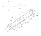
- FIG. 2 is a view for explaining light propagation in the light guide in the vehicular lamp of FIG.
- FIG. 3 is a view for explaining light propagation in the light guide in the vehicular lamp of FIG.
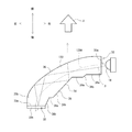
- FIG. 4 is a schematic configuration diagram of a light source and a light guide in a vehicular lamp as a modified example.
- FIG. 5 is a schematic configuration diagram of a modified example of the incident end portion of the light guide in the vehicular lamp.
- FIG. 1 shows a schematic configuration of a vehicular lamp 10 according to an embodiment of the technology of the present disclosure.
- the lamp 10 is a lighting device, and is configured as a position lamp of a vehicle headlamp, that is, a vehicle width lamp. Only the lamp 10 as the left position lamp among the left and right position lamps is schematically shown in FIG. In addition, since the position lamp on the front right side of the vehicle has a substantially symmetric configuration with the lamp 10 in FIG.
- the lamp 10 includes a lamp body 12 and a cover 14 that is attached to the opening of the lamp body 12, and has a lamp chamber 16 that is partitioned by them.
- the arrow A in FIG. 1 shows the irradiation direction of the lamp 10, More specifically, it is a front direction of a vehicle here.
- the lamp 10 includes a light source 18 and a light guide 20.
- the light source 18 and the light guide 20 are disposed and fixed in a lamp chamber 16 defined by the lamp body 12 and the cover 14.
- FIG. 1 shows fixing members 22a and 22b for fixing the light source 18 and the light guide 20 to predetermined positions.
- the fixing members 22a and 22b By the fixing by the fixing members 22a and 22b, the relative positional relationship between the light source 18 and the light guide 20 is determined, and the positioning in the vehicle is performed.
- Various fixing members or fixing mechanisms are applicable for their fixing.
- extensions 24 a and 24 b are arranged around the opening of the lamp body 12.
- a reflector (not shown) may be provided behind the light guide 20 in the lamp chamber 16 at a predetermined interval from the light guide 20, for example.
- the light source 18 is an LED light source. However, this is not intended to limit the type of light source 18.
- the fixing member 22b for fixing the light source 18 functions as a heat radiating member, but is not limited thereto.
- the light guide 20 is generally behind the light source 18 in the vehicle front-rear direction. That is, the light source 18 is on the front side of the light guide 20 in the vehicle front-rear direction, and is on the front side, that is, the irradiation direction A side in the lamp 10.
- the light guide 20 is a rod-shaped light guide, particularly a straight light guide here, and has a straight axis 20A.
- the shape of the cross section perpendicular to the axis 20A of the light guide 20 is substantially rectangular. However, this does not limit the cross-sectional shape of the light guide, and may be, for example, a substantially circular cross-section.
- the light guide 20 is made of acrylic resin. However, the light guide 20 can be made of various transparent materials other than acrylic resin, and can be made of various resin materials or glass materials.
- the light guide 20 includes an incident end 30 positioned in the vicinity of the light source 18, a reflection end 32 on the opposite side of the light guide 20 from which the incident end 30 is positioned, an incident end 30 and a reflection end.
- the light guide part 34 extended between the parts 32 is provided.
- the light guide 20 includes a configuration in which they are arranged along the axis 20 ⁇ / b> A so that the light guide 34 extends between the incident end 30 and the reflection end 32. Therefore, along the axis 20 ⁇ / b> A of the light guide 20, the incident end portion 30 is on one end side, and the reflection end portion 32 is on the other end side.
- the incident end 30 is configured such that light from the light source 18 enters the light guide 20.
- the incident end portion 30 can also be referred to as a light introducing portion.
- the light source 18 is located on the axis 20 ⁇ / b> A of the light guide 20 and is provided so as to face the incident end 30.
- the incident end 30 has an incident surface 30 a that faces the light source 18.
- the incident surface 30a is a flat surface, and is formed so that the axis 20A of the light guide 20 is orthogonal.
- the incident surface 30a is not limited to a flat surface and can be formed in other shapes.
- the incident end portion 30 is a portion of the light guide 20 that is located on the most front side in the vehicle front-rear direction, and constitutes the front end portion of the light guide 20.
- the reflection end portion 32 is a portion of the light guide 20 that is located on the rearmost side in the vehicle front-rear direction, and constitutes the rear end portion of the light guide 20.
- the reflection end portion 32 is formed so as to internally reflect light that has entered the light guide 20 by being incident from the incident end portion 30 and propagated or guided in the light guide 20 toward the reflection end portion 32. . That is, the reflection end portion 32 defines a reflection surface 32 a configured to internally reflect the light reaching the light guide 20 into the light guide 20.
- the reflection surface 32a is a flat surface and is formed so that the axis 20A of the light guide 20 is orthogonal.
- the mirror member 32b is provided here.
- the mirror member 32b is configured to form a part of the light guide 20, and the end surface of the mirror member functions as the reflection surface 32a.
- the mirror member 32b is fixed so as to be orthogonal to the light guide body 20b which is the light guide itself.
- the reflective surface 32a may be formed by forming a mirror surface on the rear end portion of the light guide 20 by vapor deposition treatment of aluminum or the like.
- the material to be vapor deposited is not limited to aluminum.
- the light guide 34 corresponds to the light guide main body 20b, and the surface shape is different between the vehicle front side and the vehicle rear side in the state of FIGS.
- the vehicle front side of the light guide 34 is configured as a smooth surface, and constitutes an emission part 36.
- the vehicle rear side of the light guide part 34 is formed in a wave shape and constitutes a step part 38.
- the step portion 38 includes a first inclined surface 38 a that extends outward from the reflecting end 32 side toward the incident end 30 side, and a reflecting end 32 side to the incident end 30 side.
- the second inclined surfaces 38b that extend inward alternately are provided as proceeding to.
- the inclination angles and areas of the plurality of first inclined surfaces 38a are substantially the same, and the inclination angles and areas of the plurality of second inclined surfaces 38b are substantially the same.
- the step part 38 is formed.
- a line L1 extending along the step portion 38 is shown in FIG. 2, and this line L1 is parallel to the axis 20A of the light guide 20 in FIG.
- the step portion 38 has the inclination angle and the area of the second inclined surface 38b determined so as to be suitable for internally reflecting a part of the light reflected by the reflecting surface 32a toward the irradiation direction A side.
- the emitting unit 36 is configured such that the light internally reflected by the step unit 38 on the irradiation direction side emits the light guide 20 on the irradiation direction A side. That is, the emission part 36 extends to the irradiation direction side of the step part 38.
- the incident end 30 is positioned so as not to be on the irradiation direction side of the emission part 36, that is, on the front side of the vehicle so as not to block the light emitted from the emission part 36 toward the irradiation direction. 1 and 2, the incident end 30 is located on the right side of the vehicle (although on the vehicle front side in the vehicle front-rear direction) of the emission unit 36.
- a virtual plane IS orthogonal to the irradiation direction A is defined so as to cross the light guide portion 34 of the light guide 20.
- the virtual surface IS is a surface extending in the vehicle left-right direction, that is, the vehicle width direction and the vertical direction.
- the incident end 30 is located in the first area ISa (on the vehicle front side or the irradiation direction side) of the two areas divided by the virtual plane IS,
- the reflecting surface 32a is located in the second region ISb (on the vehicle rear side).
- the light guide 20 is provided in the lamp chamber 16 so as to be inclined with respect to the irradiation direction A.
- the light propagation or light guide in the lamp 10 will be described with reference to FIG.
- the light source 10 When the light source 10 is turned on (operated state) by the driver's operation or the automatic lighting mechanism of the vehicle, the light from the light source 10 enters the light guide 20. Part of the incident light passes through the outer surface of the light guide 20 and does not reach the reflection end 32 because the incident angle with respect to the boundary surface (outer surface) is smaller than the critical angle. On the other hand, a part of the incident light is reflected on the reflecting surface 32 a of the reflecting end 32 by propagating through the light guide 20 while being internally reflected at the boundary surface (external surface) in the light guide 20 or without reaching the boundary surface.
- the light ⁇ enters the light guide 20 from the incident end 30 and travels while being internally reflected by the light guide 34.
- the reflection surface 32a has an orthogonal relationship with the axis 20A of the light guide 20, so that the reflection surface 32a has the same angle with respect to the axis 20A in FIG. Reflected in.
- the light ⁇ travels through the light guide unit 34 and reaches the step unit 38 of the light guide unit 34.
- the second inclined surface 38b in the step portion 38 is designed to reflect light toward the front side of the vehicle, particularly toward the irradiation direction A as described above, the light ⁇ is irradiated.
- the light is internally reflected to the direction side, and is emitted from the emitting portion 36 in the irradiation direction, that is, the vehicle front side.
- the light ⁇ enters the light guide 20 from the incident end 30 thereof, guides the light guide 34 through the light guide 20, reaches the reflection end 32, and is reflected by the reflection surface 32a.
- FIG. 3 shows, for reference, the emission of the three lights ⁇ , ⁇ , and ⁇ from the light source 18 toward the irradiation direction A side.
- the light ⁇ in FIG. 3 is the same as the light ⁇ in FIG.
- the light guide 20 including the incident end portion 30, the reflecting surface 32a, and the light guide portion 34 having the above-described configuration is used. Therefore, the light 10 having the light source 18 disposed in the vicinity of the incident end 30 on the front side of the vehicle, that is, the irradiation direction A side is irradiated with light toward the front side of the vehicle, that is, the irradiation direction A side. Is possible.
- the light guide is not limited to being straight, and may have various other shapes.
- An example of a lamp provided with a curved light guide is shown in FIG.
- the lamp of FIG. 4 is also configured as a position lamp on the front left side of the vehicle, similar to the lamp 10 described above.
- FIG. 4 only the light source 18 and the light guide 120 of the lamps as a modification are shown.
- the light guide 120 is shaped so as to be curved in a convex shape toward the vehicle outer side from the incident end portion side on the front side of the vehicle body toward the reflection end portion side of the vehicle body side according to the shape of the lamp, As shown in FIG. 4, it has a curved axis 120A.
- the light guide 120 includes an incident end 30 having an incident surface 30a, a reflecting end 32 having a reflecting surface 32a, a light emitting unit having a light emitting unit 36 and a step unit 38. 34.
- the incident surface 30a and the reflecting surface 32a are in a non-parallel relationship.
- both the incident surface 30a and the reflecting surface 32a are formed so as to be perpendicular to the axis 120A of the light guide 120.
- the light source 18 is disposed on the vehicle front side that is the irradiation direction side.
- the light ⁇ from the light source 18 enters the light guide 120 from the incident surface 30a of the incident end 30 and is reflected by the reflecting surface 32a on the opposite side.
- the light is further internally reflected by the portion 38 and can be emitted from the emitting portion 36 in the irradiation direction A.
- each inclined surface of the step part 38 is not limited to a plane, For example, it may curve partially and may be comprised as a combination of a some surface part.
- the entrance plane 30a of the entrance end part 30 was a flat surface, the light from the light source 18 is more efficiently guided to the light guide part 34 of the light guides 20 and 120. It can be formed into a shape (or configuration). As shown in FIG. 5, the incident surface 30 a may have a concave curved shape so as to surround the light source 18, for example. Further, the entire incident end portion 30 can also be formed in a substantially tapered shape as shown in FIG. 5, for example, so as to effectively guide the light taken from the incident surface 30 a by the light guide portion 34. Further, a reflection surface 30 b may be provided at the incident end 30 so that the light taken in at the incident end 30 is effectively guided by the light guide 34.
- the reflective surface 30b of the incident end 30 can be formed by installation of a mirror member, vapor deposition, or the like, similar to the reflective surface 32a of the reflective end 32.
- the technology of the present disclosure may be applied to a tail lamp, a brake lamp, or a blinker lamp in the rear of the vehicle.
- the technique of the present disclosure can be applied to lamps other than position lamps, that is, vehicle lamps.
- the light guide according to the technology of the present disclosure can be applied to a lamp other than the vehicular lamp, for example, a lamp in a living space.
- the present invention has an effect that in a lamp such as a vehicular lamp in which a light source is arranged on the irradiation direction side, light from the light source can be irradiated on the irradiation direction side. Useful.
Landscapes
- Engineering & Computer Science (AREA)
- General Engineering & Computer Science (AREA)
- Planar Illumination Modules (AREA)
- Non-Portable Lighting Devices Or Systems Thereof (AREA)
Abstract
光源(18)からの光を照射方向A側に照射するように設けられるライトガイド(20)は、光源からの光がライドガイドの内部に入射するように構成されている入射端部(30)と、ライトガイドにおいて前記入射端部が位置付けられている側とは反対側にあり、入射端部から入射した光の一部をライトガイド内に向けて内部反射させるように構成されている反射面(32a)と、それらの間に延在する導光部(34)とを備える。導光部(34)は、前記反射面で反射した光の一部を前記照射方向側に内部反射させるように構成されたステップ部(38)と、該ステップ部にて前記照射方向側に内部反射した光が出射するように構成された出射部(36)とを備える。
Description
本開示は、光源が照射方向側に配置される灯具において用いられるライトガイド及びそれを備えた車両用灯具に関する。
従来、灯室内に導光体であるライトガイドを配置し、そのライトガイドの内部において光源からの光を内面反射させてから照射方向側へ向けて出射させる車両用灯具が知られている。そのような一例が特許文献1に開示されている。
特許文献1の車両用灯具では、ランプボディと前面カバーとで区画形成された灯室内の中心部にヘッドランプ用のバルブが配置され、前面カバーは車体中央側の前方から車体側方側の後方に向かってスラントして配置され、この前面カバーに沿って湾曲した円柱状のライトガイドが配置され、更に、ライトガイドの後面側の近傍にはライトガイドと所定間隔を保つように湾曲したリフレクタが配置されている。ライトガイドの両端部に設けたLED光源からの光は、その両端部からその内部に入射し、それらの間の導光部の内部で内面反射しつつ進む。そして、特許文献1の車両用灯具では、LED光源からの光の一部を、ライトガイドの後面側の拡散ステップで内面反射させて、ライトガイドの前面側の出射部側から照射方向へ向けて出射させるようにしている。
ところで、車両によっては、ランプつまりライトの構成に制限がかかる場合がある。例えば、タイヤなど所謂足回りとの配置関係から、車両前方のヘッドランプの配置スペースを広くとることが難しい場合がある。このような場合、例えば、ヘッドランプにおいて、車両前方側に光源を配置し、その光の全部又は一部を車両前方側に照射させることが望まれる。
これに対して、上記特許文献1の、上記ライトガイドを備えた車両用灯具では、ライトガイドはわずかに車両前後方向に傾くように設けられているが、概ね車幅方向に延在するように配置されている。そして、その灯具では、ライトガイドの側方に設けた光源からライトガイドに入射した光は、入射方向に進み、つまり車幅方向の一方側から他方側に概ね進み、その一部が拡散ステップでの反射により車両前方側に向けられる。このように、特許文献1は、ヘッドランプに関するが、車両前方側に光源を配置し、その光の一部を車両前方側に出射させることに向けられていない。
本開示の技術の目的は、光源が照射方向側に配置される車両用灯具等の灯具において、その光源からの光をその照射方向側に向けて照射可能にすることにある。
上記目的を達成するために、本開示の技術は、
光源からの光を照射方向側に照射するように設けられるライトガイドであって、
前記光源からの光が前記ライドガイドの内部に入射するように構成されている入射端部と、
前記ライトガイドにおいて前記入射端部が位置付けられている側とは反対側にあり、前記入射端部から入射した光の一部を前記ライトガイド内に向けて内部反射させるように構成されている反射面と、
前記入射端部と前記反射面との間に延在する導光部であって、前記反射面で反射した光の一部を前記照射方向側に内部反射させるように構成されたステップ部と、該ステップ部にて前記照射方向側に内部反射した光が出射するように構成された出射部とを備える、導光部とを備える、ライトガイドを提供する。
光源からの光を照射方向側に照射するように設けられるライトガイドであって、
前記光源からの光が前記ライドガイドの内部に入射するように構成されている入射端部と、
前記ライトガイドにおいて前記入射端部が位置付けられている側とは反対側にあり、前記入射端部から入射した光の一部を前記ライトガイド内に向けて内部反射させるように構成されている反射面と、
前記入射端部と前記反射面との間に延在する導光部であって、前記反射面で反射した光の一部を前記照射方向側に内部反射させるように構成されたステップ部と、該ステップ部にて前記照射方向側に内部反射した光が出射するように構成された出射部とを備える、導光部とを備える、ライトガイドを提供する。
前記照射方向に直交する仮想面を前記ライトガイドの前記導光部を横断するように定めたとき、前記仮想面によって分けられる2つの領域のうちの第1領域に、前記入射端部は位置し、前記2つの領域のうちの第2領域に、前記反射面は位置してもよい。
本開示の技術は、上記ライトガイドを備えた車両用灯具も提供する。
前記反射面は、前記ライトガイドの軸線に対して略直角をなすように形成されてもよい。
前記入射端部は入射面を有し、前記入射面は、前記ライトガイドの軸線に対して略直角をなすように形成されてもよい。
前記入射面と前記反射面とは略平行であってもよい。
前記入射端部は、前記ライトガイドの第1端部に設けられ、前記反射面は、前記ライトガイドの、前記第1端部とは反対側の第2端部に設けられてもよい。
前記第2端部にはミラー部材が設けられ、該ミラー部材が、前記入射端部から入射した前記光の一部を前記ライトガイド内に向けて内部反射させるように構成されている前記反射面を構成してもよい。
本開示の上記技術によれば、上記構成を備えるので、光源が照射方向側に配置される車両用灯具等の灯具において、その光源からの光をその照射方向側に照射することが可能になる。
以下、本開示の技術に係る実施形態を添付図に基づいて説明する。同一の部品(又は構成)には同一の符号を付してあり、それらの名称及び機能も同じである。したがって、それらについての詳細な説明は繰返さない。
図1に、本開示の技術の一実施形態に係る車両用灯具10の概略構成を示す。灯具10は、照明装置であり、車両のヘッドランプのポジションランプ、つまり車幅灯として構成されている。左右のポジションランプのうち左側のポジションランプとしての灯具10のみを図1に模式的に表す。なお、車両前方右側のポジションランプは図1の灯具10と概ね左右対称の構成を備えるので、その説明を省略する。
灯具10は、ランプボディ12と、ランプボディ12の開口部に取り付けられるカバー14とを備え、それらによって区画形成された灯室16を有する。なお、図1中の矢印Aは、灯具10の照射方向を示し、より具体的にはここでは車両の前方方向である。
灯具10は、光源18と、ライトガイド20とを備える。これら光源18及びライトガイド20は、ランプボディ12とカバー14とで区画形成された灯室16内に配置固定されている。図1中には、光源18とライトガイド20とを所定位置に固定するための固定部材22a、22bが表されている。固定部材22a、22bによる固定により、光源18とライトガイド20との相対的な位置関係が定まり、及び、車両におけるそれらの位置決めがなされる。種々の固定部材又は固定機構がそれらの固定に適用可能である。また、ランプボディ12の開口部周辺には、エクステンション24a、24bが配置されている。更に、灯室16内においてライトガイド20の後方側に、ライトガイド20から例えば所定間隔をあけてリフレクタ(不図示)が設けられてもよい。
光源18は、LED光源である。しかし、これは、光源18の種類を限定することを意図しない。なお、光源18の固定用の固定部材22bは放熱部材として機能するが、これに限定されない。
ライトガイド20は、図1に示すように、概ね、光源18よりも車両前後方向において後方側にある。つまり、光源18は、車両前後方向においてライトガイド20の前方側にあり、灯具10において前方側つまり照射方向A側にある。
図2に示すように、ライトガイド20は、棒状の導光体であり、特にここでは真っ直ぐな導光体であり、まっすぐな軸線20Aを有する。特にここでは図示しないが、ライトガイド20の軸線20Aに直交する断面の形状は略矩形である。しかし、これはライトガイドの断面形状を限定するものではなく、例えば断面略円形でもよい。ライトガイド20は、ここではアクリル樹脂製である。しかし、ライトガイド20は、アクリル樹脂以外の種々の透明材料で作製可能であり、種々の樹脂材料やガラス材料などから作製され得る。
ライトガイド20は、光源18近傍に位置付けられる入射端部30と、ライトガイド20において入射端部30が位置付けられている側とは反対側にある反射端部32と、入射端部30と反射端部32との間に延在する導光部34とを備える。ライトガイド20は、入射端部30と反射端部32との間に導光部34が延在するように軸線20Aに沿ってそれらが並んで配置された構成を備える。したがって、ライトガイド20の軸線20Aに沿って、一端側に入射端部30があり、他端側に反射端部32がある。
入射端部30は、光源18からの光がライトガイド20の内部に入射するように構成されている。入射端部30は、光導入部と称することもできる。ここでは、光源18は、ライトガイド20の軸線20A上に位置するとともに、入射端部30に臨むように設けられている。入射端部30は、光源18に臨む入射面30aを有する。本実施形態では、入射面30aは平坦面であり、ライトガイド20の軸線20Aが直交するように形成されている。しかし、入射面30aは平坦面に限定されず、それ以外の形状に形成可能である。なお、図1において、入射端部30は、ライトガイド20のうちで、車両前後方向において最も前方側に位置する部分であり、ライトガイド20の前端部を構成する。
反射端部32は、ライトガイド20において、車両前後方向において最も後方側の位置する部分であり、ライトガイド20の後端部を構成する。反射端部32は、入射端部30から入射してライトガイド20内を伝播つまり導光して反射端部32に到達した光をライトガイド20内に向けて内部反射させるように形成されている。つまり、反射端部32は、そこに到達した光をライトガイド20内に内部反射させるように構成されている反射面32aを定める。反射面32aは、平面であり、ライトガイド20の軸線20Aが直交するように形成されている。なお、反射端部32においては、ここではミラー部材32bが設けられている。ミラー部材32bはライトガイド20の一部をなすように構成されていて、そのミラー部材の端面が反射面32aとして機能する。ミラー部材32bは、導光体そのものであるライトガイド本体20bに直交するように固定されている。しかし、ライトガイド20の後端部にアルミニウム等の蒸着処理等により鏡面を形成することにより、反射面32aが形成されてもよい。蒸着処理される材料は、アルミニウムに限定されない。
導光部34は、ライトガイド本体20bに相当し、図1及び図2の状態で車両前方側と車両後方側とで表面形状が異なる。図2において、導光部34の車両前方側は滑らかな面として構成され、出射部36を構成する。導光部34の車両後方側は、波状に形成されていて、ステップ部38を構成する。ステップ部38は、図2に表すように、反射端部32側から入射端部30側に進むに従い外側に拡がるように延びる第1傾斜面38aと、反射端部32側から入射端部30側に進むに従い内側に向けて延びる第2傾斜面38bとを交互に有する。ライトガイド20では、複数の第1傾斜面38a間でそれらの傾斜角度及び面積が略同じであり、また、複数の第2傾斜面38b間でそれらの傾斜角度及び面積が略同じであるように、ステップ部38は形成されている。ステップ部38に沿って延びる線L1を図2に示すが、この線L1は図2においてライトガイド20の軸線20Aに平行である。
反射面32aで反射した光の一部を照射方向A側に内部反射させるのに適するように、ステップ部38は、ここでは特に第2傾斜面38bの上記傾斜角度や上記面積は定められている。そして、出射部36は、このステップ部38にて照射方向側に内部反射された光がその照射方向A側にライトガイド20を出射するように構成されている。つまり、出射部36は、ステップ部38の照射方向側に延びている。そして、出射部36を照射方向側に出た光を遮ることがないように、入射端部30は出射部36の照射方向側つまり車両前方側にはないようにずれて位置付けられている。図1及び図2では、入射端部30は、出射部36の(車両前後方向においては車両前方側であるが)車両右側に位置する。
ここで、図1に示すように、照射方向Aに直交する仮想面ISをライトガイド20の導光部34を横断するように定める。仮想面ISは、車両左右方向つまり車幅方向かつ上下方向に延びる面である。図1から明らかなように、仮想面ISによって分けられる2つの領域のうちの(車両前方側又は照射方向側の)第1領域ISaに入射端部30は位置し、その2つの領域のうちの(車両後方側の)第2領域ISbに反射面32aは位置する。このように、ライトガイド20は、照射方向Aに対して斜めに傾いて灯室16に設けられている。
このような灯具10における光の伝播又は導光について図2に基づいて説明する。運転者の操作又は車両の自動点灯機構等により、光源10が点灯状態(作動状態)になると、光源10からの光はライトガイド20内に入射する。入射した光のうちの一部は、その境界面(外表面)に対する入射角が臨界角よりも小さいので、ライトガイド20の外表面を通過してしまい、反射端部32に至らない。一方、ライトガイド20における境界面(外部表面)で内部反射しつつ又は境界面に至らずに、ライトガイド20内を伝播することで、入射した光の一部は反射端部32の反射面32aに至る。ここで、入射した光(光線)のうち、反射端部32に至った光の一例を図2に示す。光αは、入射端部30からライトガイド20内に入り、導光部34を内部反射しつつ進む。光αは反射端部32に至ると、反射面32aがライトガイド20の軸線20Aと直交関係を有するので、図2において軸線20Aに対する同じ角度で反射面32aによってライトガイド20の導光部34内に反射される。そして、光αは、導光部34を進み、導光部34のステップ部38に至る。このとき、ステップ部38のうちの特に第2傾斜面38bは、上述のごとく、車両前方側に、特に照射方向A側に向けて光を反射するように設計されているので、光αは照射方向側に内部反射され、そして照射方向つまり車両前方側の出射部36から出射する。このように、光αは、ライトガイド20の入射端部30からその内部に入り、ライトガイド20において導光部34を導光して反射端部32に至り、反射面32aで反射されることで導光部34をそれまでとは概ね逆向きに導光し、更にステップ部38での反射により光源18側つまり車両前方側である照射方向A側に出射される。こうした光αなどにより、ライトガイド20は車両前方側つまり照射方向A側への照射を可能にする。図3に、光源18からの3つの光α、β、γの照射方向A側への出射を参考までに表す。なお、図3の光αは図2の光αと同じである。
以上説明したように、灯具10においては、上記構成の入射端部30、反射面32a及び導光部34を備えるライトガイド20が用いられる。したがって、上記姿勢のライトガイド20に対して、車両前方側つまり照射方向A側の入射端部30近傍に光源18を配置した灯具10により、車両前方側つまり照射方向A側に光を照射することが可能になる。
以上、本開示の技術における一実施形態を説明した。しかし、本開示は、上述の実施形態に限定されるものではなく、本開示の趣旨を逸脱しない範囲で、適宜に変形して実施することができる。
例えば、ライトガイドは真っ直ぐであることに限定されず、種々の他の形状を有してもよい。湾曲したライトガイドを備える灯具の一例を図4に示す。図4の灯具も、上記灯具10と同じく車両前方左側のポジションランプとして構成されている。図4では、変形例としての灯具のうちの、光源18と、ライトガイド120のみを表す。ライトガイド120は、灯具の形状に合わせて、車体中央かつ前方側の入射端部側から車体側方側の反射端部側に向かって車両外側に凸状に湾曲するように形作られていて、図4に示すように湾曲した軸線120Aを有する。ライトガイド120は、第1実施形態のライトガイド20と同じく、入射面30aを有する入射端部30と、反射面32aを有する反射端部32と、出射部36及びステップ部38を有する導光部34とを備える。しかし、ライトガイド120が湾曲しているので、入射面30aと反射面32aとは非平行の関係にある。ただし、入射面30aも反射面32aも、ライトガイド120の軸線120Aに対して直角をなすように形成されている。
このライトガイド120を備えた灯具における光の照射について図4に基づいて説明する。図4の灯具では、照射方向側である車両前方側に光源18が配置されている。図4に一例としての光δを示すように、光源18からの光δは、入射端部30の入射面30aからライトガイド120内に入射し、その反対側の反射面32aで反射され、ステップ部38で更に内部反射され、出射部36から照射方向Aに出射することができる。
なお、図4に示すように、ライトガイド120のステップ部38では、第1傾斜面38aごとの面積及び第2傾斜面38bごとの面積は個別に設定されている。これは、照射方向A側のへの光の照射又は出射を好適に生じさせるためである。このようにステップ部38の傾斜面形状は任意に定められ得、光の照射方向への内部反射を好適に生じさせるように設計されるとよい。また、ステップ部38の各傾斜面は平面であることに限定されず、例えば部分的に湾曲してもよく、複数の面部の組み合わせとして構成されてもよい。
また、上記実施形態及び上記変形例では、入射端部30の入射面30aは平坦面であったが、光源18からの光をより効率よくライトガイド20、120の導光部34に導くような形状(又は構成)に形成可能である。図5に表すように、入射面30aは、例えば光源18を囲むように、凹湾曲形状とされてもよい。また、入射端部30全体も、入射面30aから取り入れた光を導光部34により効果的に導くように、例えば図5に表すように略先細り形状に形成可能である。更に、入射端部30において取り入れた光を導光部34により効果的に導くように、入射端部30に反射面30bが設けられてもよい。入射端部30の反射面30bは、反射端部32の上記反射面32aと同様にミラー部材の設置や蒸着処理等により形成され得る。
また、車両前方のフロントランプとしての灯具を説明したが、本開示の技術は車両後方のテールランプやブレーキランプ、或は、ウィンカーランプに適用されてもよい。また、本開示の技術はポジションランプ以外のランプつまり車両用灯具に適用可能である。特に本開示の技術に係るライトガイドは、車両用灯具以外の灯具、例えば居住スペースでの灯具においても適用可能である。
本出願は、2018年3月19日付で出願された日本国特許出願(特願2018- 051112)に基づくものであり、その内容はここに参照として取り込まれる。
本発明は、光源が照射方向側に配置される車両用灯具等の灯具において、その光源からの光をその照射方向側に照射することが可能になるという効果を有し、車両用灯具等に有用である。
10 灯具
18 光源
20、120 ライトガイド
30 入射端部
30a 入射面
32 反射端部
32a 反射面
34 導光部
36 出射部
38 ステップ部
18 光源
20、120 ライトガイド
30 入射端部
30a 入射面
32 反射端部
32a 反射面
34 導光部
36 出射部
38 ステップ部
Claims (8)
- 光源からの光を照射方向側に照射するように設けられるライトガイドであって、
前記光源からの光が前記ライドガイドの内部に入射するように構成されている入射端部と、
前記ライトガイドにおいて前記入射端部が位置付けられている側とは反対側にあり、前記入射端部から入射した光の一部を前記ライトガイド内に向けて内部反射させるように構成されている反射面と、
前記入射端部と前記反射面との間に延在する導光部であって、該導光部は、
前記反射面で反射した光の一部を前記照射方向側に内部反射させるように構成されたステップ部と、
該ステップ部にて前記照射方向側に内部反射した光が出射するように構成された出射部とを備える、
ライトガイド。 - 前記照射方向に直交する仮想面を前記ライトガイドの前記導光部を横断するように定めたとき、
前記仮想面によって分けられる2つの領域のうちの第1領域に、前記入射端部は位置し、
前記2つの領域のうちの第2領域に、前記反射面は位置する、
請求項1に記載のライトガイド。 - 請求項1または2に記載のライトガイドを備えた車両用灯具。
- 前記反射面は、前記ライトガイドの軸線に対して略直角をなすように形成されている、
請求項3に記載の車両用灯具。 - 前記入射端部は入射面を有し、前記入射面は、前記ライトガイドの軸線に対して略直角をなすように形成されている、
請求項4に記載の車両用灯具。 - 前記入射面と前記反射面とは略平行である、
請求項5に記載の車両用灯具。 - 前記入射端部は、前記ライトガイドの第1端部に設けられ、
前記反射面は、前記ライトガイドの、前記第1端部とは反対側の第2端部に設けられる、
請求項3から6のいずれか一項に記載の車両用灯具。 - 前記第2端部にはミラー部材が設けられ、
該ミラー部材が、前記入射端部から入射した前記光の一部を前記ライトガイド内に向けて内部反射させるように構成されている前記反射面を構成する、
請求項7に記載の車両用灯具。
Priority Applications (1)
| Application Number | Priority Date | Filing Date | Title |
|---|---|---|---|
| CN201980020440.4A CN111868436A (zh) | 2018-03-19 | 2019-03-15 | 光导及车辆用灯具 |
Applications Claiming Priority (2)
| Application Number | Priority Date | Filing Date | Title |
|---|---|---|---|
| JP2018-051112 | 2018-03-19 | ||
| JP2018051112A JP7027991B2 (ja) | 2018-03-19 | 2018-03-19 | ライトガイド及び車両用灯具 |
Publications (1)
| Publication Number | Publication Date |
|---|---|
| WO2019181795A1 true WO2019181795A1 (ja) | 2019-09-26 |
Family
ID=67986226
Family Applications (1)
| Application Number | Title | Priority Date | Filing Date |
|---|---|---|---|
| PCT/JP2019/010882 Ceased WO2019181795A1 (ja) | 2018-03-19 | 2019-03-15 | ライトガイド及び車両用灯具 |
Country Status (3)
| Country | Link |
|---|---|
| JP (1) | JP7027991B2 (ja) |
| CN (1) | CN111868436A (ja) |
| WO (1) | WO2019181795A1 (ja) |
Families Citing this family (1)
| Publication number | Priority date | Publication date | Assignee | Title |
|---|---|---|---|---|
| KR20220141021A (ko) * | 2021-04-12 | 2022-10-19 | 현대자동차주식회사 | 차량의 램프 구조 |
Citations (3)
| Publication number | Priority date | Publication date | Assignee | Title |
|---|---|---|---|---|
| JP2010103034A (ja) * | 2008-10-27 | 2010-05-06 | Ushio Inc | 線状光源装置 |
| JP2015225819A (ja) * | 2014-05-29 | 2015-12-14 | 株式会社小糸製作所 | 車両用灯具 |
| JP2016024855A (ja) * | 2014-07-16 | 2016-02-08 | スタンレー電気株式会社 | 車両用信号灯 |
Family Cites Families (8)
| Publication number | Priority date | Publication date | Assignee | Title |
|---|---|---|---|---|
| FR2564982B1 (fr) * | 1984-05-25 | 1987-12-31 | Cibie Projecteurs | Embout de couplage d'un guide de lumiere a une source lumineuse, notamment pour un eclairage de ville integre a un ensemble projecteur pour automobile |
| DE19924411A1 (de) * | 1999-05-27 | 2000-11-30 | Hella Kg Hueck & Co | Stabförmiger Lichtleiter |
| EP1434277A4 (en) * | 2001-09-11 | 2005-01-26 | Bridgestone Corp | CONDENSATION ELEMENT AND MANUFACTURING METHOD THEREFOR AND CONDENSING ELEMENT-CARRYING LED LAMP AND LINEAR LIGHT EMITTING DEVICE WITH LED LAMP AS A LIGHT SOURCE |
| US6560038B1 (en) * | 2001-12-10 | 2003-05-06 | Teledyne Lighting And Display Products, Inc. | Light extraction from LEDs with light pipes |
| JP2011216279A (ja) * | 2010-03-31 | 2011-10-27 | Koito Mfg Co Ltd | 車両用灯具 |
| US9519153B2 (en) * | 2010-11-19 | 2016-12-13 | Reald Inc. | Directional flat illuminators |
| JP2012174641A (ja) * | 2011-02-24 | 2012-09-10 | Koito Mfg Co Ltd | 車両用灯具 |
| JP5711600B2 (ja) * | 2011-04-27 | 2015-05-07 | 株式会社小糸製作所 | 車両用灯具 |
-
2018
- 2018-03-19 JP JP2018051112A patent/JP7027991B2/ja active Active
-
2019
- 2019-03-15 CN CN201980020440.4A patent/CN111868436A/zh active Pending
- 2019-03-15 WO PCT/JP2019/010882 patent/WO2019181795A1/ja not_active Ceased
Patent Citations (3)
| Publication number | Priority date | Publication date | Assignee | Title |
|---|---|---|---|---|
| JP2010103034A (ja) * | 2008-10-27 | 2010-05-06 | Ushio Inc | 線状光源装置 |
| JP2015225819A (ja) * | 2014-05-29 | 2015-12-14 | 株式会社小糸製作所 | 車両用灯具 |
| JP2016024855A (ja) * | 2014-07-16 | 2016-02-08 | スタンレー電気株式会社 | 車両用信号灯 |
Also Published As
| Publication number | Publication date |
|---|---|
| JP7027991B2 (ja) | 2022-03-02 |
| CN111868436A (zh) | 2020-10-30 |
| JP2019164905A (ja) | 2019-09-26 |
Similar Documents
| Publication | Publication Date | Title |
|---|---|---|
| JP6714379B2 (ja) | 車両用灯具 | |
| JP5911397B2 (ja) | 車両用前照灯 | |
| US8752990B2 (en) | Vehicle light | |
| JP5091808B2 (ja) | 車両用灯具 | |
| JP6416736B2 (ja) | 車両用前照灯 | |
| JP6560514B2 (ja) | 車両用灯具 | |
| JP6857490B2 (ja) | 車両用前照灯 | |
| JP5397186B2 (ja) | 車両用灯具 | |
| JP6980377B2 (ja) | 車両用前照灯 | |
| US12560293B2 (en) | Vehicle light-guiding body and vehicle lighting unit | |
| JP6609135B2 (ja) | 車両用リアコンビネーションランプ | |
| WO2020075536A1 (ja) | 車両用導光体および車両用灯具 | |
| JP6868974B2 (ja) | 車輌用灯具 | |
| CN113892043B (zh) | 车辆用导光体以及车辆用灯具单元 | |
| CN106461179A (zh) | 车辆用导光部件、车辆用灯具 | |
| JP7148042B2 (ja) | 車両用灯具 | |
| JP2022020240A5 (ja) | ||
| JP6597024B2 (ja) | 車両用灯具 | |
| JP4898557B2 (ja) | 車両用灯具 | |
| JP7027991B2 (ja) | ライトガイド及び車両用灯具 | |
| JPH08268154A (ja) | 車両用灯具 | |
| JP2016024855A (ja) | 車両用信号灯 | |
| CN110630972B (zh) | 车辆用灯具 | |
| JP6221438B2 (ja) | 車両用灯具 | |
| KR101735637B1 (ko) | 차량용 램프 |
Legal Events
| Date | Code | Title | Description |
|---|---|---|---|
| 121 | Ep: the epo has been informed by wipo that ep was designated in this application |
Ref document number: 19771569 Country of ref document: EP Kind code of ref document: A1 |
|
| NENP | Non-entry into the national phase |
Ref country code: DE |
|
| 122 | Ep: pct application non-entry in european phase |
Ref document number: 19771569 Country of ref document: EP Kind code of ref document: A1 |