WO2019181532A1 - 引き外し装置 - Google Patents
引き外し装置 Download PDFInfo
- Publication number
- WO2019181532A1 WO2019181532A1 PCT/JP2019/009060 JP2019009060W WO2019181532A1 WO 2019181532 A1 WO2019181532 A1 WO 2019181532A1 JP 2019009060 W JP2019009060 W JP 2019009060W WO 2019181532 A1 WO2019181532 A1 WO 2019181532A1
- Authority
- WO
- WIPO (PCT)
- Prior art keywords
- iron core
- conductor
- tripping device
- movable iron
- tripping
- Prior art date
- Legal status (The legal status is an assumption and is not a legal conclusion. Google has not performed a legal analysis and makes no representation as to the accuracy of the status listed.)
- Ceased
Links
Images










Classifications
-
- H—ELECTRICITY
- H01—ELECTRIC ELEMENTS
- H01H—ELECTRIC SWITCHES; RELAYS; SELECTORS; EMERGENCY PROTECTIVE DEVICES
- H01H73/00—Protective overload circuit-breaking switches in which excess current opens the contacts by automatic release of mechanical energy stored by previous operation of a hand reset mechanism
- H01H73/36—Protective overload circuit-breaking switches in which excess current opens the contacts by automatic release of mechanical energy stored by previous operation of a hand reset mechanism having electromagnetic release and no other automatic release
Definitions
- the present invention relates to a circuit breaker trip device, in particular, in a circuit network having a main circuit breaker connected to the power supply side and a plurality of branch circuit breakers connected to the load side thereof. Only the circuit breaker operates, and the other healthy circuit relates to a circuit breaker tripping device used in a selective breaker system that continues to supply power.
- the conventional circuit breaker tripping device detects this overcurrent and executes a tripping operation when an overcurrent occurs in the circuit path of the circuit breaker.
- the tripping device operates the latch mechanism by this tripping operation and opens the contact of the opening / closing mechanism.
- the tripping device includes two types of tripping mechanisms that perform a tripping operation.
- One is a bimetal trip mechanism (hereinafter referred to as a bimetal mechanism).
- the bimetal mechanism uses the property that two types of metal are bonded together and bends at high temperatures due to the difference in thermal expansion of these metals, and the bimetal is bent by the heat generated by the resistor incorporated in the electrical circuit. Operate the mechanism.
- the other is a tripping mechanism (hereinafter referred to as a magnetic circuit mechanism section) using a magnetic circuit.
- the magnetic circuit mechanism part forms a magnetic circuit by arranging a movable iron core and a fixed iron core so as to surround the electric circuit, and the movable iron core is arranged at an initial position by an elastic force of a return spring so as to form a gap with the fixed iron core. .
- the movable core is attracted to the fixed core side and operates (for example, Patent Document 1). ).
- the overcurrent that leads the tripping device to the tripping operation is determined by the rated current of the circuit breaker. Furthermore, the time until the tripping operation needs to be changed according to the magnitude of the accident current. If the overcurrent is relatively close to the rated current, the trip device may be temporarily overloaded, so it will not operate immediately, and a time range (several seconds to (Several tens of minutes) is required to perform the tripping operation. A tripping operation (referred to as a long time operation) is performed after a relatively long time from the occurrence of such an overcurrent.
- the trip device has a relatively short time range (several milliseconds to several seconds after the overcurrent occurs). )
- a tripping operation (referred to as a short-time operation) is executed after a relatively short time from the occurrence of such an overcurrent.
- the long-time operation is set so that the bimetal mechanism is utilized, while the short-time operation is set so that the magnetic circuit mechanism is utilized.
- a protection target circuit 1000c to which the circuit breaker tripping device according to the prior art is applied is configured as shown in FIG.
- a main circuit breaker 100c having a relatively large capacity is connected to the power supply side, and a plurality of branch circuit breakers 101, branch circuit breakers 102, and branch circuit breakers are connected to the load side of the main circuit breaker 100c.
- the devices 103 are connected in parallel.
- the trip device of the main circuit breaker 100c is activated to interrupt the accident current (referred to as a trip operation).
- power supply to the branch circuit breakers 101 to 103 on the load side of the main circuit breaker 100c is also stopped.
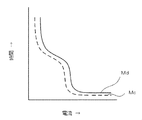
- the operation characteristic of the main circuit breaker 100c is the operation characteristic curve Md
- the operation characteristics of the branch circuit breakers 101 to 103 are the operation characteristic curve Mc. If there is, the characteristics of the main circuit breaker 100 and the branch circuit breakers 101 to 103 do not intersect with each other, so that selective interruption is possible in the entire region of overcurrent.
- the trip operation of these circuit breakers 100 to 103 is performed by a built-in trip device. To realize the above-described characteristics, the trip circuit of the main circuit breaker 100c is connected to the branch circuit breakers 101 to 103. The tripping operation only needs to be performed while the overcurrent is interrupted by 103.
- the present invention has been made to solve these problems, and an object of the present invention is to provide a circuit breaker tripping device that can be easily set with a wide setting range of the operation time of the circuit breaker. It is to be.
- the tripping device of the present invention constitutes a magnetic circuit mechanism portion by a conductor that conducts current and a movable iron core that is made of a magnetic material and is displaceably arranged. Further, when a current exceeding a preset value flows in the conductor, the magnetic circuit mechanism section increases the displacement speed of the movable iron core by the magnetic attraction force, then decreases the displacement speed, and further trips to interrupt the current. Perform the action.
- a tripping device for a circuit breaker that can be selectively cut off in a wide current range is provided, and a reliable power distribution system can be provided by this tripping device.
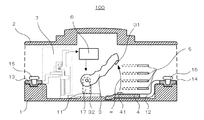
- FIG. 1 is a structural diagram of a main circuit breaker 100 to which a tripping device 7 according to Embodiment 1 of the present invention is applied.
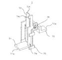
- 1 is a perspective view of a tripping device 7 according to Embodiment 1 of the present invention.
- FIG. 3 is an exploded perspective view of the trip device 7. It is a two-view figure of the movable iron core 74 of the tripping device 7. It is a side view of the tripping device in a non-operating state.
- FIG. 7 is a side view of a tripping operation state of a bimetal mechanism portion 7b of the tripping device 7.
- FIG. 7 is a side view of a tripping operation state of a magnetic circuit mechanism portion 7ma of the tripping device 7.
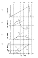
- FIG. It is a graph which shows the operating characteristic of the circuit breaker to which the tripping device 7 is applied. It is a graph which shows the time change of each parameter when the magnetic circuit mechanism part 7ma of the tripping device 7 performs the tripping operation.
- the operating state of the movable iron core 74 when the tripping device 7 is angularly displaced around the rotation shaft 76 is shown.
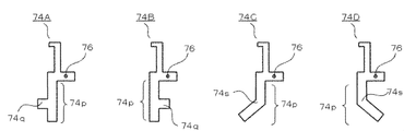
- a modification of the movable iron core 74 of the tripping device 7 is shown.
- FIG. 6 is a perspective view of the trip device 8. It is a graph which shows the time change of each parameter when the magnetic circuit mechanism part 8mc of the tripping device 8 performs a tripping operation. The operating state of the movable iron core 84 of the tripping device 8 is shown.
- FIG. 1 It is a connection diagram of a protection target circuit 1000c to which a circuit breaker to which a conventional trip device is applied is connected. It is a graph which shows the operating characteristic of the circuit breaker to which the conventional tripping device is applied. It is a perspective view of the tripping device 9 according to Embodiment 4 of the present invention. It is explanatory drawing of the magnetic flux M1 in the cross-sectional position D1 of the tripping device 9. FIG. It is explanatory drawing of the magnetic flux M2 in the cross-sectional position D2 of the tripping device 9. FIG.
- FIG. 1 is a connection diagram showing a protection target circuit 1000 to which a circuit breaker to which the tripping device 7 is applied is connected
- FIG. 2 is a structural diagram of a main circuit breaker 100 to which the tripping device 7 is applied. .
- a protection target circuit 1000 to which the tripping device 7 according to the first embodiment is applied will be described with reference to FIG.
- a main circuit breaker 100 having a relatively large capacity is connected to the power source side (terminal 100UT side), and a plurality of branch circuit breakers 101, branch circuit breakers 102, and branches are connected to the load side of the main circuit breaker 100.
- a circuit breaker 103 is connected in parallel.
- the trip device 7 is applied to the main circuit breaker 100, and the conventional trip device is applied to the branch circuit breakers 101 to 103.
- the branch circuit breaker 101 is connected to a terminal 101DT, and the terminal 101DT is connected to a load (not shown).
- the branch circuit breaker 102 is connected to another load (not shown) via a terminal 102DT
- the branch circuit breaker 103 is connected to another load (not shown) via a terminal 103DT.
- circuit breakers (100 to 103) are provided to protect the load and wiring from overcurrent and short circuit current, and when the overcurrent flows, the trip device incorporated in the circuit breaker (100 to 103) Activates and trips. The overcurrent is cut off to protect the load and wiring.
- the case 1 made of an insulating resin has a movable contact 3, a fixed contact 4, an arc extinguishing plate 5, a latch mechanism 6, a tripping device 7, a first conductor 11, a second conductor 12, The first terminal block 13, the second terminal block 14, and the connection conductor 17 are incorporated. Further, the upper part of the case 1 is covered with a cover 2 made of an insulating resin or the like.
- the movable contact 3 is configured to be rotatable around a rotation shaft 32, and includes a movable contact 31 formed at one end of the movable contact 3 and a fixed contact 41 formed on the surface of the fixed contact 4.
- a pair of contacts is configured.
- the latch mechanism 6 includes a mechanism for switching between the movable contact 31 and the fixed contact 41 from the closed state to the open state by the rotation of the movable contact 3.
- FIG. 2 shows the open state, and the arrow e indicates the direction in which the closed state is switched to the open state. Further, the latch mechanism 6 performs an operation (trip operation) for switching from the closed state to the open state by a trip operation of the trip device 7 described later.
- connection conductor 17 is electrically connected to the first conductor 11, and the first conductor 11 is connected to one end of a tripping device 7 described later, and the other end of the tripping device 7 is connected to the first terminal block 13. Is electrically connected. That is, the movable contact 31 of the movable contact 3 is electrically connected to the first terminal block 13 via the trip device 7.
- the stationary contact 4 is electrically connected to the second conductor 12.
- the second conductor 12 is electrically connected to the second terminal block 14. That is, the fixed contact 41 of the fixed contact 4 is electrically connected to the second terminal block 14.
- the main circuit breaker 100 is used with an external power source connected to the first terminal block 13 and branch circuit breakers 101 to 103 connected in parallel to the second terminal block 14.
- One terminal (not shown) of the wiring connected to the external power supply is connected to the first terminal block 13. This terminal is disposed on the first terminal block 13, and the screw 15 is fastened to the first terminal block 13 to be fixed.
- one terminal (not shown) of the wiring connected to the branch circuit breakers 101 to 103 is connected to the second terminal block 14. This terminal is disposed on the second terminal block 14, and the screw 16 is fastened and fixed to the second terminal block 14.
- FIG. 3 is a perspective view of the tripping device 7
- FIG. 4 is an exploded perspective view of the tripping device 7.
- FIG. 5 is a two-side view of the movable iron core 74 of the tripping device 7.
- the end of the first conductor 71 and the end of the second conductor 72 are electrically connected. Furthermore, the other end 71 e of the first conductor 71 is connected to the first conductor 11. Similarly, the other end 72 e of the second conductor 72 is connected to the first terminal block 13.
- the movable contact 31 of the movable contact 3 is electrically connected to the first terminal block 13 via the first conductor 71 and the second conductor 72.
- the rotating shaft 76 is passed between the two holes 74 h of the movable iron core 74. Further, the rotation shaft 76 is fixed to the notch 75 n of the fixed iron core 75, and the movable iron core 74 is disposed so as to be rotatable about the rotation shaft 76. In other words, the movable iron core 74 is disposed so as to be displaceable in a direction in which one end of the suction leg 74 p crosses the first conductor 71 during the tripping operation. Further, a return spring (not shown) is attached to the rotary shaft 76 at the shaft portion of the rotary shaft 76.
- the suction leg 74p of the movable iron core 74 is disposed so as to maintain the gap g with the fixed iron core 75 by the elastic force of the return spring.
- one end of the suction leg portion 74p opposite to the rotation support portion 74r is disposed on the side of the first conductor 71.
- the fixed iron core 75 is disposed on the side of the surface 71r of the first conductor 71.
- the movable iron core 74 and the fixed iron core 75 are made of a magnetic material, and the fixed iron core 75, the movable iron core 74, and the first conductor 71 constitute a magnetic circuit mechanism portion 7ma.
- the projecting end surface 74t of the movable iron core 74 is configured to act on the latch mechanism 6.
- the bimetal 73 obtained by bonding two metal plates having different thermal expansion coefficients is connected to the surface 71 f of one surface of the first conductor 71.
- the bimetal 73 and the first conductor 71 form a bimetal mechanism 7b.
- the end 73 t of the bimetal 73 is configured to act on the latch mechanism 6.
- FIG. 5 is a two-side view of the movable iron core 74 of the tripping device 7, showing a front view on the left side on the paper surface and a side view on the right side on the paper surface.
- the movable iron core 74 includes a rotation support portion 74r having two hole portions 74h, two suction leg portions 74p, and a movable arm portion 74a having a protrusion 74c.
- the rotation support portion 74r is bent at the left end portion and the right end portion on the plane of FIG. 5 (front view), and has holes 74h at the two bent side portions.
- one suction leg 74p is connected to the lower right end of the rotation support 74r on the paper surface of FIG. 5 (front view), and the other suction leg 74p is connected to the rotation support 74r of FIG. 5 (front view). ) Connected to the lower left edge on the page.
- the movable iron core 74 rotates around the hole 74h, and the suction leg 74p is displaced.
- the movable arm portion 74a is connected to the upper right end of the rotation support portion 74r on the paper surface of FIG. 5 (front view).
- the protrusion 74c is connected to the upper left end of the movable arm 74a on the paper surface of FIG. 5 (side view).
- the projecting end surface 74t is one surface of the left end portion of the projecting portion 74c on the paper surface of FIG. 5 (side view). In other words, the projecting end surface 74t is one surface of the projection 74c on the paper surface of FIG. 5 (front view).
- FIGS. 6 is a side view of the trip device 7 in a non-operating state
- FIG. 7 is a side view of the bimetal mechanism portion 7b of the trip device 7
- FIG. 8 is a magnetic circuit mechanism portion of the trip device 7. It is a side view of a 7ma operation state.
- FIG. 9 shows the operating characteristics of a circuit breaker to which the trip device 7 is applied.
- a trip bar 61 and a movable arm 62 which are components of the latch mechanism 6, are disposed at a position facing the protruding end surface 74 t of the tripping device 7.
- the trip bar 61 is rotatable, and the movable arm 62 is attached on the circumference of the trip bar 61. Further, the suction leg portion 74p of the movable iron core 74 is disposed so as to maintain the gap g with the fixed iron core 75 by the elastic force of the return spring (not shown).
- the tripping operation by the bimetal mechanism 7b will be described.
- the heat is transmitted to the bimetal 73, whereby the bimetal 73 is bent, and the end 73t of the bimetal 73 moves in the direction dt.
- the end portion 73t of the bimetal 73 moves in the direction dt, the end portion 73t pushes the movable arm 62, and the trip bar 61 rotates in the rotation direction rt.
- the latch mechanism 6 is a mechanism for switching the movable contact 3 and the fixed contact 41 from the closed state to the open state when the trip bar 61 rotates and the movable contact 3 rotates about the rotation shaft 32. Prepare. That is, when the end portion 73t performs a pulling operation for pressing the movable arm 62, the latch mechanism 6 performs a trip operation.
- the latch mechanism 6 is configured such that when the trip bar 61 rotates, the movable contact 3 rotates about the rotation shaft 32 and the movable contact 31 and the fixed contact 41 are closed. A mechanism for switching from a state to an open state is provided. That is, when the end portion 73t performs a pulling operation for pressing the movable arm 62, the latch mechanism 6 performs a trip operation.
- the operation characteristics of the main circuit breaker 100 to which the tripping device 7 is applied will be described with reference to FIG.
- the horizontal axis indicates the current value
- the vertical axis indicates time.
- the vertical axis may be linear or logarithmic.
- the operating characteristic curve Mm shows the current dependency of the operating time of the circuit breaker to which the tripping device 7 is applied, and this operating time starts when the tripping device 7 starts the tripping operation, and the circuit breaker enters the trip operation.
- This current value is a current value flowing through the first conductor 71.
- the main circuit breaker 100 is set so that the bimetal mechanism 7b is utilized for the long-time operation, while the magnetic circuit mechanism is used for the short-time operation.
- the part 7ma is set to be utilized.
- the operating characteristic curve Mc indicates the current dependency of the operating time of the circuit breaker to which the conventional tripping device is applied.
- the circuit breaker will not trip and will continue to supply power to the load. That is, the tripping device 7 does not perform the tripping operation.
- the tripping device 7 executes the long time operation for a relatively long time between the operation time Tm and the operation time Tt after the occurrence of such an overcurrent.
- the tripping operation by the magnetic circuit mechanism unit 7ma of the tripping device 7 is executed, and the circuit breaker is tripped. That is, the trip device 7 performs a short time operation in a relatively short time from the occurrence of such an overcurrent to an operation time Tm or less.
- the trip operation started by the bimetal mechanism 7b and the magnetic circuit mechanism 7ma described above is also executed by a circuit breaker to which a conventional tripping device is applied.
- a circuit breaker to which a conventional tripping device is applied.
- the difference in operation between the conventional tripping device and the tripping device 7 shown in the first embodiment will be described. Referring to FIG. 10 and FIG. 11, when the magnetic circuit mechanism portion 7ma of the tripping device 7 performs a tripping operation to reach a short time operation, and when the conventional tripping device performs the tripping operation, The case of reaching the operation will be described.
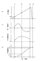
- FIG. 10 shows a case where the current value flowing through the first conductor 71 becomes equal to or greater than the current threshold value Im, and the magnetic circuit mechanism unit 7ma of the tripping device 7 reaches the tripping operation, and the conventional tripping device trips the operation. It is a graph which shows the time change of each parameter in the case of reaching.
- FIG. 10A shows the change over time of the current value flowing through the first conductor 71 of the trip device 7.
- FIG. 10B shows a characteristic curve Vb of time variation of the rotational torque generated on the rotation shaft 76 of the tripping device 7 and a characteristic curve Cb of time variation of the rotational torque generated on the rotation shaft of the conventional tripping device. Indicates.
- FIG. 10A shows the change over time of the current value flowing through the first conductor 71 of the trip device 7.
- FIG. 10B shows a characteristic curve Vb of time variation of the rotational torque generated on the rotation shaft 76 of the tripping device 7 and a characteristic curve Cb of time variation of
- FIG. 10C shows a characteristic curve Vc of the angular velocity of the rotating shaft 76 of the tripping device 7 with time and a characteristic curve Cc of the angular velocity of the rotating shaft of the conventional tripping device with time.
- FIG. 10 (d) shows a characteristic curve Vd of the temporal change of the angular displacement of the rotary shaft 76 of the tripping device 7 and a characteristic curve Cd of the temporal change of the angular displacement of the rotary shaft of the conventional tripping device. .
- the characteristics of the conventional tripping device are shown under the following constant conditions.
- the maximum value of the angular displacement of the conventional tripping device is the same as the maximum angular displacement amount ⁇ 4 of the tripping device 7, and the time until the maximum angular displacement amount ⁇ 4 is reached is time tc4.
- the context of time tc4 and time t2, which will be described later, is displayed when time tc4> time t2.
- time tc4 time t2> time t2.
- FIG. 11 shows the operating state of the movable iron core 74 when the value of the current flowing through the first conductor 71 is equal to or greater than the current threshold value Im and angular displacement occurs in the rotating shaft 76.
- the operation state of the movable iron core 74 only the first conductor 71, the second conductor 72, the movable iron core 74, and the rotating shaft 76 of the tripping device 7 are shown in the drawing. Note that the counterclockwise rotation on the paper surface of FIG. 11 will be described as a positive direction.
- FIG. 11A shows a non-operating state of the tripping device 7 as in FIG. FIG.
- FIG. 11B shows a state in which the value of the current flowing through the first conductor 71 becomes equal to or greater than the current threshold value Im, a positive direction rotational torque is generated, and the movable iron core 74 starts operating.
- FIG. 11C is a state after FIG. 11B, and shows a state when the rotational torque becomes zero. Further, FIG. 11D shows a state after FIG. 11C, in which the rotational torque is in a negative direction.
- FIG. 11A shows a state between time zero and time t1 before the value of the current flowing through the first conductor 71 becomes equal to or greater than the current threshold value Im.
- the rotation torque is not generated or negligible between time zero and time t1. Therefore, the angular velocity is zero and the angular displacement is zero.
- the suction leg 74p of the movable iron core 74 holds the gap g with the fixed iron core 75 by the elastic force of the return spring. That is, the suction leg 74p maintains the initial position.
- FIG. 11B shows one state between time t1 and time t2.
- a concentric magnetic field is generated around the first conductor 71.
- the strength increases, and the magnetic attractive force between the fixed iron core 75 and the attraction leg 74p of the movable iron core 74 is enhanced. Furthermore, this magnetic attraction force exceeds the elastic force of the return spring, generating a positive rotational torque. Due to this rotational torque, a positive angular velocity is generated, and the angular displacement becomes the positive angular displacement ⁇ 1.
- the angular displacement amount ⁇ 1 is a point that is greater than zero and less than the angular displacement amount ⁇ 2, which will be described later.
- the rotational torque in the positive direction is generated and the angular velocity increases. .
- FIG. 11C shows a state at time t2.
- time t2 is the time when the rotational torque becomes zero, and the angular displacement amount in this case is angular displacement amount ⁇ 2.
- the suction leg 74p approaches the fixed iron core 75, the magnetic attraction force between the fixed iron core 75 and the suction leg 74p decreases, and the elastic force of the return spring balances with the magnetic attraction force, resulting in rotational torque. It becomes zero.
- the rotational torque is zero, but the positive angular velocity is maintained. That is, the movement continues according to the law of inertia.
- the suction leg 74p is moved away from the fixed iron core 75, the magnetic attraction force is increased again between the fixed iron core 75 and the suction leg 74p, and the elastic force of the return spring is also applied in the negative direction. Increases in the negative direction.
- the suction leg 74p is displaced in a direction crossing the fixed iron core 75 and the first conductor 71, reaches the surface 71r side of the first conductor 71 on the right side of FIG. 11 and moves away from the fixed iron core 75.
- the suction legs 74p are arranged at both ends of the rotation support portion 74r, the suction legs 74p can be displaced to the surface 71r side of the first conductor 71.
- FIG. 11D shows a state at time t3.
- time t3 is the time when trip device 7 executes the short time operation.
- the latch mechanism 6 performs a trip operation, and the current flowing through the first conductor 71 decreases rapidly.
- the angular displacement amount is the angular displacement amount ⁇ 3.
- the maximum angular displacement amount ⁇ 4 is the maximum value of the angular displacement amount and is determined by the mechanical configuration of the tripping device 7. Furthermore, the time when the maximum angular displacement amount ⁇ 4 is reached is time t4.
- the angular displacement amount ⁇ 3 at which the short time operation is executed is set to a value between the angular displacement amount ⁇ 2 and the maximum angular displacement amount ⁇ 4 at which the rotational speed is negative and the angular velocity is reduced. That is, the tripping operation is set to be executed between time t2 and time t4.
- the movable iron core 74 is displaced while increasing the angular velocity, and then displaced while decreasing the angular velocity, and then the trip device 7.
- Performs a tripping operation (short-time operation).
- the movable iron core 74 is displaced while increasing the operation speed, and then is displaced while decreasing the operation speed.
- the tripping device 7 executes a tripping operation (short-time operation).
- the tripping device 7 according to the first embodiment will be described.
- the tripping device 7 according to the first embodiment is set so that the tripping operation is performed between the time t2 and the time t4. For example, by adjusting the distance between the protruding end surface 74t and the movable arm 62, the time until the tripping operation can be easily set.
- the tripping device 7 is set so as to execute the tripping operation between the time t1 and the time t4. It is also possible to do.
- the conventional tripping device does not include a mechanism for turning the rotational torque from positive to negative, and as shown by the characteristic curve Cb, the angular velocity also increases. Just do not decrease. That is, in the conventional tripping device, the tripping operation is executed between time t1 and time tc4. Therefore, when the maximum angular displacement amount of the conventional tripping device is compared as the maximum angular displacement amount ⁇ 4 of the tripping device 7, time tc4 ⁇ time t4.
- the main circuit breaker 100 and the branch circuit breakers 101 to 103 are configured only by the conventional tripping device. It is difficult to provide a difference between the operation time of the main circuit breaker 100 and the operation time of the branch circuit breakers 101 to 103.
- the tripping device 7 of the first embodiment constitutes the main circuit breaker 100, and the conventional tripping device comprises the branch circuit breakers 101 to 103, so that the operation time of the main circuit breaker 100 can be reduced. Since the operation time of the branch circuit breakers 101 to 103 can be set to the time t1 to the time tc4 by setting the time tc4 to the time t4, a difference from the operation time can be easily provided.
- the difference in the time setting for the short time operation between the tripping device 7 of the first embodiment and the conventional tripping device is mainly due to the structure of the movable iron core 74.
- the suction leg portion 74p is connected to both ends of the rotation support portion 74r, the suction leg portion 74p is displaced in a direction crossing the fixed iron core 75 and the first conductor 71, and further, Since it is configured to be displaceable up to the surface 71r side, the tripping operation can be set between time t2 and time t4.
- the movable iron core is not provided with a structure that can rotate to the surface 71r side of the first conductor 71, and therefore the tripping operation cannot be set between time tc4 and time t4. .
- the long time operation by the bimetal mechanism 7b will be described. Since it is possible to provide a degree of curvature due to temperature by distributing the thickness of the two metal plates of bimetal, the tripping device 7 of the first embodiment and the conventional tripping device operate for a long time. The current region can be easily set.
- the operation characteristic curve Mm of the main circuit breaker 100 and the operation characteristic curve Mc of the branch circuit breakers 101 to 103 do not easily intersect with each other due to the setting of the bimetal mechanism 7b and the setting of the magnetic circuit mechanism 7ma.
- the application of the tripping device 7 of the first embodiment makes it possible to easily perform selective interruption in the entire overcurrent region.
- circuit breaker trip device that can easily set a wide range of operation time of the circuit breaker and can be selectively cut off in a wide current range. . Furthermore, this tripping device can provide a highly reliable power distribution system.
- FIG. 12 shows a modification of the movable iron core 74 that changes the center of gravity and the weight of the movable iron core 74.
- the movable iron core 74A has a convex portion 74q on the left side of the drawing surface of the suction leg portion 74p.
- the convex portion 74q is heavier than the movable iron core 74, and the center of gravity is set on the left side of the drawing compared to the movable iron core 74.
- the movable iron core 74B has a convex portion 74q in the portion on the right side of the drawing leg of the suction leg portion 74p.
- the convex portion 74q is heavier than the movable iron core 74, and the center of gravity is set on the right side of the drawing compared to the movable iron core 74.
- the movable iron core 74C has a curved portion 74s at the portion of the suction leg portion 74p, and is formed so that a portion below the paper surface of the suction leg portion 74p bends leftward on the paper surface.
- the center of gravity is set on the left side of the paper surface as compared with the movable iron core 74.
- the movable iron core 74D has a curved portion 74s at the suction leg portion 74p, and is formed such that a portion below the paper surface of the suction leg portion 74p is bent in the right direction on the paper surface.
- the center of gravity is set on the right side of the drawing compared to the movable iron core 74. Even if a bending portion is provided between the movable arm 62 and the rotation support portion 74r and the movable arm 62 is formed to bend rightward or leftward on the paper surface, the position of the center of gravity is set.
- the time until the tripping operation can be easily set. It can. Furthermore, by adjusting the gap g, the time until the tripping operation can be easily set by moving the initial position of the suction leg 74p.
- Embodiment 2 when the value of the current flowing through the first conductor 71 is equal to or greater than the current threshold value Im, the movable iron core 74 is displaced while increasing the angular velocity, and then decreasing the angular velocity. It has been explained that the displacement and then the tripping operation is performed.
- the movable iron core 74 when the value of the current flowing through the first conductor 71 is equal to or greater than the current threshold value Im, the movable iron core 74 is displaced while increasing the angular velocity, and thereafter is displaced while decreasing the angular velocity, and again the angular velocity.
- a tripping device 7A that displaces while moving up and then executes a tripping operation will be described.
- FIG. 13 is a graph showing the time change of each parameter when the value of the current flowing through the first conductor 71 becomes equal to or greater than the current threshold value Im and the magnetic circuit mechanism unit of the tripping device 7 reaches the tripping operation.
- 13A shows the time change of the current value flowing through the first conductor 71
- FIG. 13B shows the time change of the rotational torque generated in the rotating shaft 76
- FIG. The time change of angular velocity is shown.
- FIG. 13D shows a change with time of the angular displacement of the rotating shaft 76.
- FIG. 14 shows the operating state of the movable iron core 74 when the value of the current flowing through the first conductor 71 becomes equal to or greater than the current threshold value Im and angular displacement occurs in the rotating shaft 76.
- the operation state of the movable iron core 74 only the first conductor 71, the second conductor 72, the movable iron core 74, and the rotating shaft 76 of the tripping device 7A are shown in the drawing. Note that the counterclockwise rotation on the paper surface of FIG. 14 will be described as a positive direction.
- the suction leg 74p is fixed by the magnetic attractive force between the fixed iron core 75 and the movable iron core 74.
- the movable iron core 74 is attracted to the iron core 75 and rotated in the forward direction, and thereafter, a tripping operation is executed.
- the tripping device 7 ⁇ / b> A according to the second embodiment electrically connects the second conductor 72 to the first conductor 71.
- the second conductor 72 is disposed at a position where a magnetic attraction force is generated between the second conductor 72 and the suction leg 74p after the suction leg 74p is displaced and the movable iron core 74 is angularly displaced. Composed.
- the suction leg 74p is configured to be displaceable in the direction of the second conductor 72. That is, in the tripping device 7A according to the second embodiment, similarly to the tripping device 7, the fixed iron core 75, the movable iron core 74, and the first conductor 71 constitute the magnetic circuit mechanism portion 7ma. , And the second conductor 72 constitute a magnetic circuit mechanism portion 7mb.
- FIG. 14A shows a state between time zero and time t1 before the value of the current flowing through the first conductor 71 becomes equal to or greater than the current threshold value Im, as in FIG. 11A.
- the rotation torque is not generated or negligible between time zero and time t1. Therefore, the angular velocity is zero and the angular displacement is zero. That is, the suction leg 74p maintains the initial position.
- FIG. 14B shows one state between time t1 and time t2, similarly to FIG. 11B.
- a concentric magnetic field is generated around first conductor 71.
- the strength increases, and the magnetic attractive force between the fixed iron core 75 and the attraction legs 74p of the movable iron core 74 is also increased. Further, this magnetic attraction force exceeds the elastic force of the return spring, and a positive rotational torque is generated. Due to this rotational torque, a positive angular velocity is generated, and the angular displacement becomes the positive angular displacement ⁇ 1.
- the angular displacement amount ⁇ 1 is a point that is greater than zero and less than the angular displacement amount ⁇ 2, which will be described later.
- the rotational torque in the positive direction is generated and the angular velocity increases. .
- the rotational torque becomes zero, and the angular displacement amount in this case is the angular displacement amount ⁇ 2.
- the rotational torque is zero, but the positive angular velocity is maintained. That is, the movement continues according to the law of inertia.
- the angular displacement amount becomes larger than the angular displacement amount ⁇ 2 from time t2 to t5 after the elapse of time.
- the movable iron core 74 is moved away from the fixed iron core 75, the magnetic attraction force is increased again between the fixed iron core 75 and the movable iron core 74, the elastic force of the return spring is also applied in the negative direction, and the negative rotational torque is increased. Strengthen.
- FIG. 14C shows a state at time t5.
- time t5 is a time when the rotational torque becomes zero again, and the angular displacement amount in this case is angular displacement amount ⁇ 5.
- This state is a state in which the magnetic attraction force between the fixed iron core 75 and the attraction leg portion 74p and the magnetic attraction force between the attraction leg portion 74p and the second conductor 72 are balanced and the rotational torque becomes zero. .
- FIG. 14D shows the state at time t6.
- time t6 is a time when trip device 7A executes the short time operation.
- the angular displacement amount in this case is the angular displacement amount ⁇ 6.
- the angular displacement ⁇ 7 is the maximum value of the angular displacement and is determined by the mechanical configuration of the tripping device 7A.
- the time when the angular displacement amount ⁇ 7 is reached is time t7. That is, the time for which the tripping device 7A executes the tripping operation is set to the time t6 between the time t5 and the time t7.
- This state is a state in which the magnetic attractive force between the movable iron core 74 and the second conductor 72 is greater than the magnetic attractive force between the fixed iron core 75 and the movable iron core 74, and the balanced rotational torque is in the positive direction.
- the tripping operation is performed between time t2 and time t4.
- the tripping operation is performed at time t2. It can be set to execute during time t7. That is, the tripping device 7A according to the second embodiment can extend the period for setting the tripping operation, compared with the tripping device 7 according to the first embodiment.
- the movable iron core 74 is displaced while increasing the operation speed, and then is displaced while decreasing the operation speed. Displacement is performed while increasing the angular velocity, and then the tripping device 7A executes a tripping operation (short-time operation), so the period for setting the tripping operation can be extended.
- the tripping operation can be set to be executed between the times t1 and t2
- the tripping device 7A is set to execute the tripping operation between the times t1 and t7. It is also possible to do.
- this tripping device can provide a highly reliable power distribution system.
- the tripping device (7, 7A) has the movable iron cores 74, 74A to 74D centered on the rotation shaft 76 when the current value flowing through the first conductor 71 is equal to or greater than the current threshold value Im. It has been explained that the displacement operation is performed and the tripping operation is executed.
- the movable iron core 84 of the tripping device 8 moves straight and performs the tripping operation.
- the third embodiment will explain a tripping device 8 that is applied only to a short time operation.
- Embodiment 3 of the present invention will be described in detail with reference to FIGS. 15 to 18, the same reference numerals or reference numerals as those in FIGS. 1 to 14 are the same as or equivalent to the components shown in the first embodiment, and detailed description thereof is omitted.
- FIGS. 15 and 16 are cross-sectional views of the tripping device 8 in a non-operating state
- FIG. 16 is a perspective view for explaining the positions of the movable rod 81, the first conductor 82, and the movable iron core 84 of the components of the tripping device 8.
- the first conductor 82 is disposed so as to surround the movable iron core 84. Furthermore, one end of the first conductor 82 is connected to the first terminal block 13 (not shown), and the other end of the first conductor 82 is connected to the first conductor 11 (not shown).
- a movable bar 81 is connected to the upper part of the movable iron core 84.
- the fixed iron core 85 is disposed so as to surround the movable rod 81 and the first conductor 82, and has an opening so that the movable rod 81 passes through the upper portion of the fixed iron core 85.
- the movable bar 81 is configured to be linearly movable in the vertical direction on the paper surface of FIG. 15, and a trip bar 61 is disposed above the end 81t of the movable bar 81 (not shown).
- the first conductor 82, the movable iron core 84, and the fixed iron core 85 constitute the magnetic circuit mechanism unit 8mc of the tripping device 8, and perform a short time operation.
- FIG. 17 is a graph showing the time change of each parameter when the value of the current flowing through the first conductor 82 becomes equal to or greater than the current threshold value Im and the magnetic circuit mechanism unit 8mc reaches the tripping operation.
- 17A shows the time change of the current value flowing through the first conductor 82
- FIG. 17B shows the time change of the driving force generated in the movable core 84
- FIG. It shows the time change of the straight speed.
- FIG. 17D shows a change over time of the linear displacement of the movable core 84.
- FIG. 18 shows an operating state of the movable iron core 84 when the value of the current flowing through the first conductor 82 becomes equal to or greater than the current threshold value Im and the movable iron core 84 is displaced.
- the description will be made assuming that the direction from the bottom to the top in FIG. 18 is the positive direction.
- FIG. 18A shows a non-operating state of the tripping device 8 as in FIG.
- FIG. 18B shows a state in which the value of the current flowing through the first conductor 82 is equal to or greater than the current threshold value Im, a positive force is generated, and the movable iron core 84 starts operating.
- FIG. 18C is a state after FIG. 18B, and shows a state when the driving force applied to the movable iron core 84 becomes zero.
- FIG. 18D shows a state after FIG. 18C, in which the driving force applied to the movable iron core 84 is in the negative direction.
- FIG. 18A shows a state between time zero and time t1 before the current value flowing through the first conductor 82 becomes equal to or greater than the current threshold value Im.
- the initial position is stabilized by the elastic force of the return spring, and the driving force applied to the movable iron core 84 is not generated or can be ignored. is there. Accordingly, the straight speed is zero and the straight displacement is zero.
- FIG. 18B shows one state between time t1 and time t2.
- the value of the current flowing through the first conductor 82 becomes equal to or greater than the current threshold value Im from time t1 to time t2
- a concentric magnetic field is generated around the first conductor 82.
- the strength increases, and the magnetic attractive force between the upper portion 85u of the fixed iron core 85 and the movable iron core 84 is also increased. Furthermore, this magnetic attraction force exceeds the elastic force of the return spring, and a positive driving force is generated.
- This driving force generates a speed in the positive direction, and the amount of linear displacement becomes the amount of linear displacement L1 in the positive direction.
- the rectilinear displacement amount L1 is one point that is greater than zero and less than the rectilinear displacement amount L2, which will be described later. is there.
- FIG. 18C shows a state at time t2.
- time t2 is the time when the driving force becomes zero, and the linear displacement amount is linear displacement L2.
- the driving force becomes zero because the elastic force of the return spring increases as the movable iron core 84 approaches the upper portion 85u of the fixed iron core 85, and the elastic force of the return spring balances with the magnetic attractive force.
- the driving force is zero, but the speed in the positive direction is maintained. That is, the movement continues according to the law of inertia. Further, since the speed in the positive direction is maintained at time t2, the linear displacement amount becomes larger than the linear displacement amount L2 after time t2.
- FIG. 18D shows a state at time t3.
- time t3 is a time when trip device 8 executes the short time operation.
- the latch mechanism 6 performs an operation of switching from the closed state to the open state, the current flowing through the first conductor 82 is rapidly reduced. In this case, it is the linear displacement L3.
- the rectilinear displacement amount L4 is the maximum value of the rectilinear displacement amount, and is determined by the mechanical configuration of the tripping device 8.
- the time when reaching the straight displacement L4 is time t4.
- the rectilinear displacement amount L3 at which the short time operation is executed is set to be a value between the rectilinear displacement amount L2 and the rectilinear displacement amount L4 at which the driving force is negative and the angular velocity is reduced.
- the movable iron core 84 is displaced while increasing the straight traveling speed, and then is displaced while decreasing the straight traveling speed.
- the removal device 8 performs a tripping operation.
- the movable iron core 84 is displaced while increasing the operating speed, and then is displaced while decreasing the operating speed.
- the tripping device 8 performs a tripping operation.
- the tripping operation can be set between time t2 and time t4, so that selective shutoff is easy. Will be possible.
- the tripping operation can be set to be executed between the time t1 and the time t2
- the tripping device 8 is set to execute the tripping operation between the time t1 and the time t4. It is also possible to do.
- a tripping device for a circuit breaker that can be easily set with a wide setting range of the operation time of the circuit breaker and can be selectively cut off in a wide current range. . Furthermore, this tripping device can provide a highly reliable power distribution system.
- Embodiment 4 FIG.
- the tripping operation is performed as follows.
- a concentric magnetic field is generated around the first conductor 71, and a magnetic attractive force is generated between the fixed iron core 75 and the movable iron core 74.
- this magnetic attractive force (hereinafter referred to as a positive magnetic attractive force) attracts the attracting leg portion 74p of the movable iron core 74 to the fixed iron core 75, and the movable iron core 74 rotates in the rotation direction rm.
- the projecting end surface 74t of the movable iron core 74 moves in the direction dm, and the tripping device 7 executes the tripping operation.
- one end of the suction leg 74p of the tripping device 7 is displaced in a direction crossing the first conductor 71, and a tripping operation is executed.
- a magnetic attraction force (hereinafter, opposite) is prevented in a direction that prevents one end of the attraction leg portion 74p from being displaced in a direction crossing the first conductor 71.
- the tripping device 9 that generates a magnetic attracting force in the direction) will be described.
- the magnetic attracting force in the positive direction exceeds the magnetic attracting force in the opposite direction, and the movable iron core 74 rotates in the rotational direction rm and performs the tripping operation.
- FIGS. 21 is a perspective view of the tripping device 9
- FIG. 22 is an explanatory view of the magnetic flux M1 at the cross-sectional position D1 surrounded by a dotted line in FIG. 21, and
- FIG. 23 is a cross-sectional position surrounded by a dotted line in FIG. It is explanatory drawing of the magnetic flux M2 in D2.
- the cross-sectional position D1 indicates a position of a cross section including an initial suction portion 95c and a suction leg portion 74p, which will be described later
- the cross-sectional position D2 is a position of a cross section below the tripping device 9 compared to the cross-sectional position D1.
- the initial suction part 95c is not included, and the suction leg part 74p is included.
- 21 to 23 the same reference numerals or the same reference numerals as those in FIGS. 1 to 12 are the same as or equivalent to the components shown in the first embodiment, and thus detailed description thereof is omitted.
- the main difference in structure between the tripping device 9 of the fourth embodiment and the tripping device 7 of the first embodiment is the difference in structure between the fixed iron core 95 and the fixed iron core 75.
- the fixed iron core 95 has a fixed arm portion 95b whose one end is connected to the main body portion 95a of the fixed iron core 95, and an initial suction portion 95c connected to the other end of the fixed arm portion 95b.
- the fixed iron core 75 does not have the initial adsorption part 95c.
- the fixed arm portion 95b is disposed so that one end of the suction leg portion 74p extends in a direction opposite to the direction crossing the first conductor 71 during the tripping operation, and the initial suction portion 95c is in the initial position. It arrange
- the fixed arm portion 95b and the initial attracting portion 95c are made of a magnetic material.
- the magnetic flux M ⁇ b> 1 is a magnetic flux that is generated when a current flows through the first conductor 71 and circulates around the first conductor 71, and is interposed between the fixed core 95 and the movable iron core 74 by the magnetic flux M ⁇ b> 1. Produces positive magnetic attraction.
- the path of the magnetic flux M1 will be described.
- the magnetic flux M1 branches from the main body portion 95a of the fixed iron core 95 through the fixed arm portion 95b on the right side of the paper, and branches into the magnetic flux M1m and the magnetic flux M1s at the initial attracting portion 95c on the right side of the paper.
- the magnetic flux M1m passes from the initial suction part 95c on the right side of the paper through the space between the initial suction part 95c on the right side of the paper and the initial suction part 95c on the left side of the paper, and reaches the initial suction part 95c on the left side of the paper.
- the magnetic flux M1s passes through the space between the suction leg 74p on the right side of the paper and the suction leg 74p on the left side of the paper through the suction leg 74p on the right side of the paper from the initial suction part 95c on the right side of the paper. Reaches the suction leg 74p.
- the magnetic flux M1s reaches the initial suction portion 95c on the left side of the paper surface from the suction leg portion 74p on the left side of the paper surface.
- the magnetic flux M1m and the magnetic flux M1s merge at the initial adsorption portion 95c on the left side of the page to become the magnetic flux M1.
- the magnetic flux M1 passes through the fixed arm portion 95b on the left side of the paper, reaches the main body portion 95a, and circulates.
- the magnetic flux M1s passes from the initial suction part 95c on the right side of the paper to the suction leg part 74p on the right side of the paper and from the suction leg part 74p on the left side of the paper to the initial suction part 95c on the left side of the paper.
- a magnetic attraction force is generated between the suction leg 74p.
- a magnetic attractive force in the opposite direction is generated. That is, at the initial position, a magnetic attractive force in the positive direction is generated by the magnetic flux M1, and a magnetic attractive force in the opposite direction is also generated at the same time.
- the magnetic flux M2 is a magnetic flux that is generated when a current flows through the first conductor 71 and circulates around the first conductor 71, and between the fixed iron core 75 and the movable iron core 74 by the magnetic flux M2. Produces positive magnetic attraction.
- the path of the magnetic flux M2 will be described.
- the magnetic flux M2 passes through the space between the main body 95a of the fixed iron core 95 and the suction leg 74p on the right side of the paper, and reaches the suction leg 74p on the right side of the paper.
- the magnetic flux M2 passes through the space between the suction leg 74p on the right side of the paper and the suction leg 74p on the left side of the paper, and reaches the suction leg 74p on the left side of the paper. Further, the magnetic flux M2 reaches the main body portion 95a through the space between the suction leg portion 74p on the left side of the paper surface and the main body portion 95a, and circulates. Further, since the magnetic flux M2 branches and does not pass from the initial attracting portion 95c to the attracting leg portion 74p, no magnetic attracting force in the opposite direction is generated. In other words, the magnetic flux M2 does not generate a magnetic attractive force in the opposite direction, but generates a magnetic attractive force in the positive direction.
- the position where the magnetic attractive force in the opposite direction is generated is only the portion of the suction leg portion 74p where the initial attracting portion 95c approaches or contacts in the initial position, but the other suction leg portion 74p is in the forward direction. Only magnetic attraction force is generated. That is, there are more parts where only the magnetic attractive force in the forward direction is generated than parts where the magnetic attractive force in the opposite direction is generated. For this reason, the total amount of magnetic attractive force in the positive direction exceeds the total amount of magnetic attractive force in the opposite direction.
- the magnetic attracting force in the opposite direction rapidly decreases due to the distance between the initial attracting portion 95c and the attracting leg portion 74p. For this reason, when the movable iron core 74 starts to be displaced from the initial position, the influence of the magnetic attraction force in the opposite direction on the rotation of the movable iron core 74 rapidly decreases.
- the tripping device 9 performs a tripping operation.
- the tripping device 9 of the fourth embodiment has a higher current threshold Im than the tripping device 7 of the first embodiment because the magnetic attracting force in the positive direction needs to exceed the magnetic attraction force in the opposite direction. It is possible to set. Further, it is possible to set the magnetic saturation amount of the magnetic flux M1s by setting the area close to or in contact with the suction leg 74p of the initial attracting portion 95c at the initial position, the cross-sectional area of the path of the magnetic flux M1s, and the like. The strength of the magnetic attractive force in the opposite direction can be set.
- the current threshold value Im is set by setting the area close to or in contact with the suction leg portion 74p of the initial attracting portion 95c at the initial position, the cross-sectional area of the path of the magnetic flux M1s, and the tripping device 9 performs the tripping operation
- the time to reach can be set.
- the tripping devices (7, 7A) of the first and second embodiments determine the current threshold value Im based on the elastic force of the return spring and the positive magnetic attraction force. Since the tripping device 9 can independently set the magnetic attractive force in the opposite direction, the setting range of the current threshold Im can be expanded.
- this tripping device can provide a highly reliable power distribution system.
- the movable iron cores 74 and 74A have two suction legs 74p.
- the suction legs 74p are displaced to the surface 71r side of the first conductor 71. If the structure is displaced, the number of suction legs 74p may be one. The present invention does not limit the number of suction legs 74p.
- fixed iron core 75 is made of a magnetic material. Even if the fixed iron core 75 made of a magnetic material is not disposed, if a sufficient magnetic attraction force acts between the first conductor 71 and the movable iron core 74, the fixed iron core 75 made of a magnetic material is installed. There is no need, and instead of the fixed iron core 75, a member other than the magnetic body that holds the movable iron core 74 may be used. For example, examples of this member include aluminum and plastic. Further, when a member other than the magnetic body instead of the fixed iron core 75 holds the movable iron core 74, the magnetic circuit mechanism portion 7 ma includes the movable iron core 74 and the first conductor 71.
- the first conductor 71 and the second conductor 72 are connected in series.
- the first conductor 71 and the second conductor 72 are integrally formed. It may be good. That is, the present invention does not limit the method of forming the first conductor 71 and the second conductor 72.
- the tripping device (7, 7A, 8, 9) of the present invention is applied to the main circuit breaker 100, and the conventional tripping device is applied to the branch circuit breakers 101 to 103.
- the tripping device (7, 7A, 8, 9) of the present invention is also applied to the main circuit breaker 100 and the branch circuit breakers 101 to 103 until the tripping operation is performed. By setting the time individually, it is possible to easily perform selective blocking.
- the connection of the two-level circuit breaker in which the branch circuit breakers 101 to 103 are connected in parallel to the main circuit breaker 100 has been described.
- the tripping device (7, 7A, 8, 9) of the present invention is also applied to the connection of the three-level circuit breakers that connect the branch circuit breakers, and the time until the tripping operation is individually set. By doing so, selective blocking can also be easily performed. That is, the present invention does not limit the number of circuit breaker connection levels. In the configuration of the conventional tripping device, the problem that it is difficult to connect the circuit breakers of three or more layers because the setting range of the operation time of the conventional tripping device is narrow is more serious. On the other hand, according to the present invention, the selection interruption can be easily performed by individually setting the time until the trip operation of the trip device.
- the non-operating gap g is held by the elastic force of the return spring
- the return spring is not necessarily required, and an elastic body such as plastic may be used. That is, the present invention does not limit the type of elastic body corresponding to the first return spring.
- the non-operating gap g is held by the elastic force of the return spring, it is not necessary to hold the operating gap g by the elastic force.
- the moving core 74 is held by its own weight or the position of the center of gravity. You may do it. That is, the method of the gap g in the non-operating state of the present invention is not limited.
- the embodiments can be freely combined, or the embodiments can be appropriately changed or omitted.
- the first conductor 71 and the first conductor 82 are the first conductors described in the claims.
- the magnetic circuit mechanism unit 7ma and the magnetic circuit mechanism unit 8mc are the first magnetic circuit mechanism unit described in the claims.
- the magnetic circuit mechanism portion 7mb is a second magnetic circuit mechanism portion described in the claims.
- the second conductor 72 is a second conductor described in the claims.
Landscapes
- Physics & Mathematics (AREA)
- Electromagnetism (AREA)
- Breakers (AREA)
Abstract
本発明により、回路遮断器の動作時間を容易に設定可能な回路遮断器の引き外し装置を得る。 本発明の引き外し装置は、電流を導通する導体と、この導体との磁気吸引力により変位する磁性体で構成された可動鉄心とで、構成された磁気回路機構部を備える。 さらに、予め設定された以上の電流が導体に流れる場合、磁気回路機構部は、磁気吸引力により可動鉄心の変位速度を上昇し、その後に変位速度を低下し、さらに前記電流を遮断する引き外し動作を行う。
Description
この発明は、回路遮断器の引き外し装置、特に電源側に接続される主回路遮断器とその負荷側に接続される複数の分岐回路遮断器がある回路網において、事故回路に直接関係する分岐回路遮断器のみが動作し、他の健全な回路はそのまま給電を継続する選択遮断システムに利用される回路遮断器の引き外し装置に関するものである。
従来の回路遮断器の引き外し装置は、回路遮断器の電路に過電流が発生した場合、この過電流を検知し、引き外し動作を実行する。引き外し装置は、この引き外し動作によりラッチ機構を動作させ、開閉機構の接点を開極する。
なお、引き外し装置には、引き外し動作を実行する2種類の引き外し機構を備える。
1つは、バイメタル方式による引き外し機構(以下、バイメタル機構部と称する)である。バイメタル機構部は、2種類の金属を張り合わせ、これらの金属の熱膨張の差により高温時に湾曲する性質を利用しており、電路に組み込まれた抵抗体の発熱によりバイメタルが湾曲することで、ラッチ機構を動作させる。
もう1つは、磁気回路による引き外し機構(以下、磁気回路機構部と称する)である。
磁気回路機構部は、電路を囲むように可動鉄心と固定鉄心を配置することで磁気回路を形成し、可動鉄心は固定鉄心とギャップができるように復帰バネの弾性力により初期位置に配置される。電路を流れる電流が大きくなり、可動鉄心を初期位置に押し返す復帰バネの荷重よりも可動鉄心に働く電磁力が大きくなった場合に可動鉄心が固定鉄心側に吸引され動作する(例えば、特許文献1)。
なお、引き外し装置には、引き外し動作を実行する2種類の引き外し機構を備える。
1つは、バイメタル方式による引き外し機構(以下、バイメタル機構部と称する)である。バイメタル機構部は、2種類の金属を張り合わせ、これらの金属の熱膨張の差により高温時に湾曲する性質を利用しており、電路に組み込まれた抵抗体の発熱によりバイメタルが湾曲することで、ラッチ機構を動作させる。
もう1つは、磁気回路による引き外し機構(以下、磁気回路機構部と称する)である。
磁気回路機構部は、電路を囲むように可動鉄心と固定鉄心を配置することで磁気回路を形成し、可動鉄心は固定鉄心とギャップができるように復帰バネの弾性力により初期位置に配置される。電路を流れる電流が大きくなり、可動鉄心を初期位置に押し返す復帰バネの荷重よりも可動鉄心に働く電磁力が大きくなった場合に可動鉄心が固定鉄心側に吸引され動作する(例えば、特許文献1)。
一般的に、引き外し装置が、引き外し動作に至る過電流は回路遮断器の定格電流によって決定される。さらに、引き外し動作に至るまでの時間は事故電流の大きさによって変更する必要がある。
過電流が定格電流に比較的近い場合、引き外し装置は、一時的な過負荷状態の場合もあるので即動作させず、過電流が発生してから熱的に問題のない時間範囲(数秒~数十分程度)で、引き外し動作を実行することが求められる。このような過電流発生から比較的長時間後に引き外し動作(長限時動作と称する)を実行する。
一方、短絡事故時のように過電流が定格電流の何倍もの電流が瞬間的に流れた場合、引き外し装置は、過電流が発生してから比較的短い時間範囲(数ミリ秒~数秒程度)で引き外し動作を実行することが求められる。このような過電流発生から比較的短時間後に引き外し動作(短限時動作と称する)を実行する。
なお、長限時動作には、バイメタル機構部が活用されるように設定され、一方、短限時動作には、磁気回路機構部が活用されるように設定される。
過電流が定格電流に比較的近い場合、引き外し装置は、一時的な過負荷状態の場合もあるので即動作させず、過電流が発生してから熱的に問題のない時間範囲(数秒~数十分程度)で、引き外し動作を実行することが求められる。このような過電流発生から比較的長時間後に引き外し動作(長限時動作と称する)を実行する。
一方、短絡事故時のように過電流が定格電流の何倍もの電流が瞬間的に流れた場合、引き外し装置は、過電流が発生してから比較的短い時間範囲(数ミリ秒~数秒程度)で引き外し動作を実行することが求められる。このような過電流発生から比較的短時間後に引き外し動作(短限時動作と称する)を実行する。
なお、長限時動作には、バイメタル機構部が活用されるように設定され、一方、短限時動作には、磁気回路機構部が活用されるように設定される。
従来技術における回路遮断器の引き外し装置が適用される保護対象回路1000cは、図19に示すように構成されている。
図19において、電源側に比較的容量の大きい主回路遮断器100cが接続され、この主回路遮断器100cの負荷側に複数個の分岐回路遮断器101、分岐回路遮断器102、および分岐回路遮断器103が並列に接続されている。
主回路遮断器100cの負荷側S0の地点で事故が発生した場合、主回路遮断器100cの引き外し装置が作動して、事故電流が遮断される(トリップ動作と称する)。しかしながら、同時に主回路遮断器100cの負荷側にある分岐回路遮断器101~103に対する給電も全て停止してしまう。
つぎに、分岐回路遮断器103の負荷側S3の地点で事故が発生する場合を挙げる。この場合、事故電流が流れるのは主回路遮断器100cおよび分岐回路遮断器103であり、主回路遮断器100cがトリップ動作してしまうことで健全な回路である分岐回路遮断器101および分岐回路遮断器102への給電も停止してしまう。しかしながら、可能な限り健全な回路への給電は継続させる必要がある。
図19において、電源側に比較的容量の大きい主回路遮断器100cが接続され、この主回路遮断器100cの負荷側に複数個の分岐回路遮断器101、分岐回路遮断器102、および分岐回路遮断器103が並列に接続されている。
主回路遮断器100cの負荷側S0の地点で事故が発生した場合、主回路遮断器100cの引き外し装置が作動して、事故電流が遮断される(トリップ動作と称する)。しかしながら、同時に主回路遮断器100cの負荷側にある分岐回路遮断器101~103に対する給電も全て停止してしまう。
つぎに、分岐回路遮断器103の負荷側S3の地点で事故が発生する場合を挙げる。この場合、事故電流が流れるのは主回路遮断器100cおよび分岐回路遮断器103であり、主回路遮断器100cがトリップ動作してしまうことで健全な回路である分岐回路遮断器101および分岐回路遮断器102への給電も停止してしまう。しかしながら、可能な限り健全な回路への給電は継続させる必要がある。
そこで、分岐回路遮断器101~103の負荷側で発生する事故への対策として、事故に直接関係する分岐回路遮断器のみが動作して他の健全な回路はそのまま給電を継続させる選択遮断が必要である。この選択遮断では主回路遮断器100cと分岐回路遮断器101~103の両者の動作特性曲線を考慮する必要があり、分岐回路遮断器101~103のいずれかの負荷側で事故が発生した場合、この分岐回路遮断器が事故電流を遮断する時間の間だけ、主回路遮断器のトリップ動作を遅らせなければならない。
例えば、図20に示す遮断に至る時間の電流依存性のように、主回路遮断器100cの動作特性が動作特性曲線Mdであり、分岐回路遮断器101~103の動作特性が動作特性曲線Mcであるとすれば、主回路遮断器100と分岐回路遮断器101~103との特性は交差していないため過電流の全領域で選択遮断が可能である。
これらの回路遮断器100~103のトリップ動作は組み込まれている引き外し装置によって行われており、前述した特性を実現させるには、主回路遮断器100cの引き外し装置に分岐回路遮断器101~103が過電流を遮断する間だけ引き外し動作させないようすればよい。
例えば、図20に示す遮断に至る時間の電流依存性のように、主回路遮断器100cの動作特性が動作特性曲線Mdであり、分岐回路遮断器101~103の動作特性が動作特性曲線Mcであるとすれば、主回路遮断器100と分岐回路遮断器101~103との特性は交差していないため過電流の全領域で選択遮断が可能である。
これらの回路遮断器100~103のトリップ動作は組み込まれている引き外し装置によって行われており、前述した特性を実現させるには、主回路遮断器100cの引き外し装置に分岐回路遮断器101~103が過電流を遮断する間だけ引き外し動作させないようすればよい。
しかしながら、特許文献1のような従来の引き外し装置の構成では、主回路遮断器100cと分岐回路遮断器101~103との動作特性曲線を図20に示すように交差しないように設定にすることは、引き外し装置の動作時間の設定幅が狭いために困難であるといった問題がある。
この発明は、これらの課題を解決するためになされたものであり、この発明の目的は、回路遮断器の動作時間の設定幅が広く、容易に設定可能な回路遮断器の引き外し装置を提供することである。
本発明の引き外し装置は、電流を導通する導体と、磁性体で構成され変位可能に配置された可動鉄心とで、磁気回路機構部を構成する。
さらに、予め設定された以上の電流が導体に流れる場合、磁気回路機構部は、磁気吸引力により可動鉄心の変位速度を上昇し、その後に変位速度を低下し、さらに前記電流を遮断する引き外し動作を行う。
さらに、予め設定された以上の電流が導体に流れる場合、磁気回路機構部は、磁気吸引力により可動鉄心の変位速度を上昇し、その後に変位速度を低下し、さらに前記電流を遮断する引き外し動作を行う。
この発明によれば、広い電流範囲で選択遮断可能な回路遮断器の引き外し装置を提供することであり、この引き外し装置により高信頼な配電系統を提供することができる。
実施の形態1.
以下、この発明の実施の形態1について、図1~12を参照し詳細に説明する。
はじめに、図1および図2を参照して、引き外し装置が適用される回路遮断器の構造、および回路遮断器の接続を説明する。
図1は、引き外し装置7が適用される回路遮断器の接続する保護対象回路1000を示す接続図であり、図2は引き外し装置7が適用される主回路遮断器100の構造図である。
以下、この発明の実施の形態1について、図1~12を参照し詳細に説明する。
はじめに、図1および図2を参照して、引き外し装置が適用される回路遮断器の構造、および回路遮断器の接続を説明する。
図1は、引き外し装置7が適用される回路遮断器の接続する保護対象回路1000を示す接続図であり、図2は引き外し装置7が適用される主回路遮断器100の構造図である。
図1を参照して、実施の形態1に係る引き外し装置7が適用される保護対象回路1000を説明する。
電源側(端子100UTの側)に比較的容量の大きい主回路遮断器100が接続され、この主回路遮断器100の負荷側に複数個の分岐回路遮断器101、分岐回路遮断器102、および分岐回路遮断器103が並列に接続されている。また、主回路遮断器100には、引き外し装置7が適用され、分岐回路遮断器101~103には、従来の引き外し装置が適用される。
さらに、分岐回路遮断器101は端子101DTに接続され、端子101DTは負荷(図示せず)に接続される。同様に、分岐回路遮断器102は端子102DTを介し別の負荷(図示せず)に接続され、分岐回路遮断器103は端子103DTを介し、さらに別の負荷(図示せず)に接続される。
電源側(端子100UTの側)に比較的容量の大きい主回路遮断器100が接続され、この主回路遮断器100の負荷側に複数個の分岐回路遮断器101、分岐回路遮断器102、および分岐回路遮断器103が並列に接続されている。また、主回路遮断器100には、引き外し装置7が適用され、分岐回路遮断器101~103には、従来の引き外し装置が適用される。
さらに、分岐回路遮断器101は端子101DTに接続され、端子101DTは負荷(図示せず)に接続される。同様に、分岐回路遮断器102は端子102DTを介し別の負荷(図示せず)に接続され、分岐回路遮断器103は端子103DTを介し、さらに別の負荷(図示せず)に接続される。
これらの回路遮断器(100~103)は負荷や配線を過電流および短絡電流から保護するために設けられており、過電流が流れると回路遮断器(100~103)に組み込まれた引き外し装置が作動し、トリップ動作を実行する。過電流を遮断して負荷や配線の保護が行われる。
分岐回路遮断器103の負荷側S3の地点で事故が発生した場合は、事故電流が流れるのは主回路遮断器100および分岐回路遮断器103である。主回路遮断器100がトリップ動作してしまう場合、健全な回路である分岐回路遮断器101および分岐回路遮断器102への給電を停止してしまう。このような分岐回路遮断器101および分岐回路遮断器102への給電を停止しないようにするために、主回路遮断器100のトリップ動作よりも先に分岐回路遮断器103がトリップ動作を実行する。すなわち、選択遮断動作が行われる。
同様に、分岐回路遮断器101の負荷側の地点および分岐回路遮断器102の負荷側の地点で事故が発生した場合にも、選択遮断動作が行われる。
同様に、分岐回路遮断器101の負荷側の地点および分岐回路遮断器102の負荷側の地点で事故が発生した場合にも、選択遮断動作が行われる。
つぎに、図2を参照して、主回路遮断器100の構造を説明する。
絶縁性樹脂などで構成されるケース1には、可動接触子3、固定接触子4、アーク消弧板5、ラッチ機構6、引き外し装置7、第1導電体11、第2導電体12、第1端子台13、第2端子台14、および接続導体17が内蔵される。
さらに、ケース1の上部を、絶縁性樹脂などで構成されたカバー2で覆う。
絶縁性樹脂などで構成されるケース1には、可動接触子3、固定接触子4、アーク消弧板5、ラッチ機構6、引き外し装置7、第1導電体11、第2導電体12、第1端子台13、第2端子台14、および接続導体17が内蔵される。
さらに、ケース1の上部を、絶縁性樹脂などで構成されたカバー2で覆う。
可動接触子3は、回転軸32を中心に回動可能に構成され、可動接触子3の一端に形成された可動接点31と、固定接触子4の表面に形成された固定接点41とで、一対の接点を構成する。
ラッチ機構6は、可動接触子3の回動により可動接点31と固定接点41との間を閉状態から開状態へ切り替える機構を備える。なお、図2は開状態を示し、矢印eは閉状態から開状態に切り替わる方向を示す。
また、ラッチ機構6は、後述する引き外し装置7の引き外し動作により、閉状態から開状態に切り替える動作(トリップ動作)を実行する。
ラッチ機構6は、可動接触子3の回動により可動接点31と固定接点41との間を閉状態から開状態へ切り替える機構を備える。なお、図2は開状態を示し、矢印eは閉状態から開状態に切り替わる方向を示す。
また、ラッチ機構6は、後述する引き外し装置7の引き外し動作により、閉状態から開状態に切り替える動作(トリップ動作)を実行する。
さらに、可動接触子3は、接続導体17に電気的に接続される。接続導体17は、第1導電体11に電気的に接続され、第1導電体11は、後述する引き外し装置7の一端に接続され、引き外し装置7のもう一端は、第1端子台13に電気的に接続される。すなわち、可動接触子3の可動接点31は、引き外し装置7を介して第1端子台13に電気的に接続される。
一方、固定接触子4は、第2導電体12に電気的に接続される。第2導電体12は、第2端子台14に電気的に接続される。すなわち、固定接触子4の固定接点41は、第2端子台14に電気的に接続される。
なお、主回路遮断器100は、第1端子台13に外部の電源が接続され、第2端子台14に並列に分岐回路遮断器101~103が接続された状態で使用される。
第1端子台13には、外部の電源に接続された配線の一方の端子(図示せず)が接続される。この端子は、第1端子台13の上に配置され、ネジ15を第1端子台13に締め込み固定される。
同様に、第2端子台14には、分岐回路遮断器101~103に接続された配線の一方の端子(図示せず)が接続される。この端子は、第2端子台14の上に配置され、ネジ16を第2端子台14に締め込み固定される。
第1端子台13には、外部の電源に接続された配線の一方の端子(図示せず)が接続される。この端子は、第1端子台13の上に配置され、ネジ15を第1端子台13に締め込み固定される。
同様に、第2端子台14には、分岐回路遮断器101~103に接続された配線の一方の端子(図示せず)が接続される。この端子は、第2端子台14の上に配置され、ネジ16を第2端子台14に締め込み固定される。
なお、第1端子台13と第2端子台14との間に電圧が印加され、可動接点31と固定接点41との間に電流が流れている場合、閉状態から開状態に切り替わった直後では、可動接点31と固定接点41との間にアーク放電が発生することがある。
アーク放電にローレンツ力を作用させ、アーク放電をアーク消弧板5に衝突させ、消弧させる。
アーク放電にローレンツ力を作用させ、アーク放電をアーク消弧板5に衝突させ、消弧させる。
つぎに、図3~図5を参照して、引き外し装置7の構造および引き外し装置7の可動鉄心74を説明する。
図3は引き外し装置7の斜視図であり、図4は引き外し装置7の分解斜視図である。さらに、図5は引き外し装置7の可動鉄心74の二面図である。
図3は引き外し装置7の斜視図であり、図4は引き外し装置7の分解斜視図である。さらに、図5は引き外し装置7の可動鉄心74の二面図である。
まず、図3および図4を参照して、引き外し装置7の構造を説明する。
第1導体71の端部と第2導体72の端部とは電気的に接続される。さらに、第1導体71のもう一方の端部71eは、第1導電体11と接続される。同様に、第2導体72のもう一方の端部72eは、第1端子台13と接続される。なお、可動接触子3の可動接点31は、第1導体71と第2導体72とを介して第1端子台13に電気的に接続される。
第1導体71の端部と第2導体72の端部とは電気的に接続される。さらに、第1導体71のもう一方の端部71eは、第1導電体11と接続される。同様に、第2導体72のもう一方の端部72eは、第1端子台13と接続される。なお、可動接触子3の可動接点31は、第1導体71と第2導体72とを介して第1端子台13に電気的に接続される。
回転軸76は、可動鉄心74の2つの穴部74hの間を通される。さらに、回転軸76は、固定鉄心75の切り欠き部75nに固定され、可動鉄心74は回転軸76を中心に回動可能に配置される。言い換えると、引き外し動作の時には可動鉄心74は、吸引脚部74pの一端が第1導体71を横切る方向に変位可能に配置される。
さらに、回転軸76に、復帰バネ(図示せず)が、回転軸76の軸の部分に取り付けられる。後述する引き外し装置7の非動作状態では、この復帰バネの弾性力により、可動鉄心74の吸引脚部74pは、固定鉄心75とのギャップgを保つように配置される。言い換えると、初期位置(非動作状態)では、吸引脚部74pの回転支持部74rの側とは反対側の一端は、第1導体71の側方に配置される。
さらに、回転軸76に、復帰バネ(図示せず)が、回転軸76の軸の部分に取り付けられる。後述する引き外し装置7の非動作状態では、この復帰バネの弾性力により、可動鉄心74の吸引脚部74pは、固定鉄心75とのギャップgを保つように配置される。言い換えると、初期位置(非動作状態)では、吸引脚部74pの回転支持部74rの側とは反対側の一端は、第1導体71の側方に配置される。
また、固定鉄心75は、第1導体71の面71rの側方に配置される。
可動鉄心74と固定鉄心75とは、磁性体で構成され、固定鉄心75、可動鉄心74、および第1導体71とで磁気回路機構部7maを構成する。
なお、後述するように、可動鉄心74の突端面74tは、ラッチ機構6に作用するように構成される。
可動鉄心74と固定鉄心75とは、磁性体で構成され、固定鉄心75、可動鉄心74、および第1導体71とで磁気回路機構部7maを構成する。
なお、後述するように、可動鉄心74の突端面74tは、ラッチ機構6に作用するように構成される。
さらに、熱膨張率が異なる2枚の金属板を貼り合わせたバイメタル73は、第1導体71の一つの面の面71fに接続される。バイメタル73と第1導体71とで、バイメタル機構部7bを形成する。なお、後述するように、バイメタル73の端部73tは、ラッチ機構6に作用するように構成される。
つぎに、図5を参照して、引き外し装置7の可動鉄心74の構造を説明する。
図5は引き外し装置7の可動鉄心74の二面図であり、紙面上の左側に正面図を示し、紙面上の右側に側面図を示す。
可動鉄心74は、2つの穴部74hを有する回転支持部74rと、2個の吸引脚部74pと、突起部74cを有する可動腕部74aとで構成される。
回転支持部74rは、図5(正面図)紙面上の左端部と右端部とはそれぞれ折れ曲がり、この2つの折れ曲がった辺部に、それぞれ穴部74hを有する。
図5は引き外し装置7の可動鉄心74の二面図であり、紙面上の左側に正面図を示し、紙面上の右側に側面図を示す。
可動鉄心74は、2つの穴部74hを有する回転支持部74rと、2個の吸引脚部74pと、突起部74cを有する可動腕部74aとで構成される。
回転支持部74rは、図5(正面図)紙面上の左端部と右端部とはそれぞれ折れ曲がり、この2つの折れ曲がった辺部に、それぞれ穴部74hを有する。
さらに、一方の吸引脚部74pは、回転支持部74rの図5(正面図)紙面上の下方の右端部に接続され、他方の吸引脚部74pは、回転支持部74rの図5(正面図)紙面上の下方の左端部に接続される。後述するように、可動鉄心74は穴部74hを中心に回動し、吸引脚部74pは変位する。
可動腕部74aは、回転支持部74rの図5(正面図)紙面上の上方の右端部に接続される。さらに、突起部74cは、可動腕部74aの図5(側面図)紙面上の上方の左端部に接続される。また、突端面74tは、突起部74cの図5(側面図)紙面上の左端部の一面である。言い換えると、突端面74tは、突起部74cの図5(正面図)紙面上の一面である。
可動腕部74aは、回転支持部74rの図5(正面図)紙面上の上方の右端部に接続される。さらに、突起部74cは、可動腕部74aの図5(側面図)紙面上の上方の左端部に接続される。また、突端面74tは、突起部74cの図5(側面図)紙面上の左端部の一面である。言い換えると、突端面74tは、突起部74cの図5(正面図)紙面上の一面である。
つぎに、図6~図9を参照して、引き外し装置7の動作を説明する。
図6は引き外し装置7の非動作状態の側面図であり、図7は引き外し装置7のバイメタル機構部7bの動作状態の側面図であり、図8は引き外し装置7の磁気回路機構部7maの動作状態の側面図である。さらに、図9は、引き外し装置7を適用した回路遮断器の動作特性を示す。
図6は引き外し装置7の非動作状態の側面図であり、図7は引き外し装置7のバイメタル機構部7bの動作状態の側面図であり、図8は引き外し装置7の磁気回路機構部7maの動作状態の側面図である。さらに、図9は、引き外し装置7を適用した回路遮断器の動作特性を示す。
図6を参照して、引き外し装置7の突端面74tに対向する位置には、ラッチ機構6の構成部品であるトリップバー61と可動腕62とが配置される。トリップバー61は、回動可能であり、可動腕62はトリップバー61の周上に取り付けられる。
また、可動鉄心74の吸引脚部74pは、復帰バネ(図示せず)の弾性力により固定鉄心75とのギャップgを保つように配置される。
また、可動鉄心74の吸引脚部74pは、復帰バネ(図示せず)の弾性力により固定鉄心75とのギャップgを保つように配置される。
図7を参照して、バイメタル機構部7bによる引き外し動作を説明する。
バイメタル73に接続された第1導体71が通電により加熱されると、バイメタル73に熱が伝わることによりバイメタル73が湾曲し、バイメタル73の端部73tは、方向dtに動く。
さらに、バイメタル73の端部73tが方向dtに動くと、端部73tは可動腕62を押し、トリップバー61は、回転方向rtに回動する。
また、ラッチ機構6は、トリップバー61が回動する場合、可動接触子3が回転軸32を中心に回転し、可動接点31と固定接点41との間を閉状態から開状態へ切り替える機構を備える。すなわち、端部73tが可動腕62を押す引き外し動作を実行した場合、ラッチ機構6は、トリップ動作を遂行する。
バイメタル73に接続された第1導体71が通電により加熱されると、バイメタル73に熱が伝わることによりバイメタル73が湾曲し、バイメタル73の端部73tは、方向dtに動く。
さらに、バイメタル73の端部73tが方向dtに動くと、端部73tは可動腕62を押し、トリップバー61は、回転方向rtに回動する。
また、ラッチ機構6は、トリップバー61が回動する場合、可動接触子3が回転軸32を中心に回転し、可動接点31と固定接点41との間を閉状態から開状態へ切り替える機構を備える。すなわち、端部73tが可動腕62を押す引き外し動作を実行した場合、ラッチ機構6は、トリップ動作を遂行する。
図8を参照して、磁気回路機構部7maによる引き外し動作を説明する。
第1導体71に過電流が流れると、第1導体71の周りに同心円状の磁場が発生し、固定鉄心75と可動鉄心74との間に磁気吸引力が発生する。
この磁気吸引力により可動鉄心74の吸引脚部74pは、固定鉄心75に引き寄せられ、可動鉄心74は、回転軸76を中心に回転方向rmに回動し、可動鉄心74の突端面74tは、方向dmに動く。言い換えると、当初、吸引脚部74pは、ギャップgが狭くなる方向に動く。さらに、突端面74tは可動腕62を押し、トリップバー61は、回転方向rtに回動する。
バイメタル機構部7bの場合と同様に、ラッチ機構6は、トリップバー61が回動する場合、可動接触子3が回転軸32を中心に回転し、可動接点31と固定接点41との間を閉状態から開状態へ切り替える機構を備える。すなわち、端部73tが可動腕62を押す引き外し動作を実行した場合、ラッチ機構6は、トリップ動作を遂行する。
第1導体71に過電流が流れると、第1導体71の周りに同心円状の磁場が発生し、固定鉄心75と可動鉄心74との間に磁気吸引力が発生する。
この磁気吸引力により可動鉄心74の吸引脚部74pは、固定鉄心75に引き寄せられ、可動鉄心74は、回転軸76を中心に回転方向rmに回動し、可動鉄心74の突端面74tは、方向dmに動く。言い換えると、当初、吸引脚部74pは、ギャップgが狭くなる方向に動く。さらに、突端面74tは可動腕62を押し、トリップバー61は、回転方向rtに回動する。
バイメタル機構部7bの場合と同様に、ラッチ機構6は、トリップバー61が回動する場合、可動接触子3が回転軸32を中心に回転し、可動接点31と固定接点41との間を閉状態から開状態へ切り替える機構を備える。すなわち、端部73tが可動腕62を押す引き外し動作を実行した場合、ラッチ機構6は、トリップ動作を遂行する。
図9を参照して、引き外し装置7を適用した主回路遮断器100の動作特性を説明する。
横軸は電流値を示し、縦軸は時間を示す。なお、主回路遮断器100の動作の設定により、縦軸は線形である場合も対数である場合もある。動作特性曲線Mmは、引き外し装置7を適用した回路遮断器の動作時間の電流依存性を示し、この動作時間は、引き外し装置7が引き外し動作を開始し、回路遮断器がトリップ動作に至るまでの時間であり、この電流値は、第1導体71を流れる電流値である。
横軸は電流値を示し、縦軸は時間を示す。なお、主回路遮断器100の動作の設定により、縦軸は線形である場合も対数である場合もある。動作特性曲線Mmは、引き外し装置7を適用した回路遮断器の動作時間の電流依存性を示し、この動作時間は、引き外し装置7が引き外し動作を開始し、回路遮断器がトリップ動作に至るまでの時間であり、この電流値は、第1導体71を流れる電流値である。
前述した従来の回路遮断器の引き外し装置と同様に、主回路遮断器100では、長限時動作にはバイメタル機構部7bが活用されるように設定され、一方、短限時動作には磁気回路機構部7maが活用されるように設定される。なお、動作特性曲線Mcは、従来の引き外し装置を適用した回路遮断器の動作時間の電流依存性を示す。
電流値が電流定格値It未満の場合、回路遮断器はトリップ動作に至ることはなく、負荷に電力の供給を続ける。すなわち、引き外し装置7は、引き外し動作を実行しない。
電流値が、電流定格値It以上かつ電流しきい値Im未満の場合、引き外し装置7のバイメタル機構部7bによる引き外し動作が実行され、主回路遮断器100はトリップ動作に至る。
すなわち、引き外し装置7は、このような過電流発生から動作時間Tm~動作時間Ttの間の比較的長時間で長限時動作を実行する。
すなわち、引き外し装置7は、このような過電流発生から動作時間Tm~動作時間Ttの間の比較的長時間で長限時動作を実行する。
電流値が、電流しきい値Im以上の場合、引き外し装置7の磁気回路機構部7maによる引き外し動作が実行され、回路遮断器がトリップ動作に至る。
すなわち、引き外し装置7は、このような過電流発生から動作時間Tm以下の比較的短時間で短限時動作を実行する。
すなわち、引き外し装置7は、このような過電流発生から動作時間Tm以下の比較的短時間で短限時動作を実行する。
前述したバイメタル機構部7bおよび磁気回路機構部7maにより始動されるトリップ動作は、従来の引き外し装置を適用する回路遮断器でも実行される。
つぎに、従来の引き外し装置と本実施の形態1に示す引き外し装置7との動作の違いを説明する。
図10および図11を参照して、引き外し装置7の磁気回路機構部7maが引き外し動作を実行し短限時動作に至る場合と、従来の引き外し装置が引き外し動作を実行し、短限時動作に至る場合とについて説明する。
つぎに、従来の引き外し装置と本実施の形態1に示す引き外し装置7との動作の違いを説明する。
図10および図11を参照して、引き外し装置7の磁気回路機構部7maが引き外し動作を実行し短限時動作に至る場合と、従来の引き外し装置が引き外し動作を実行し、短限時動作に至る場合とについて説明する。
図10は、第1導体71を流れる電流値が電流しきい値Im以上となり、引き外し装置7の磁気回路機構部7maが引き外し動作に至る場合と従来の引き外し装置が動作を引き外し動作至る場合の各パラメータの時間変化を示すグラフである。
図10(a)は引き外し装置7の第1導体71を流れる電流値の時間変化を示す。図10(b)は、引き外し装置7の回転軸76に発生する回転トルクの時間変化の特性曲線Vbと、従来の引き外し装置の回転軸に発生する回転トルクの時間変化の特性曲線Cbとを示す。図10(c)は、引き外し装置7の回転軸76の角速度の時間変化の特性曲線Vcと、従来の引き外し装置の回転軸の角速度の時間変化の特性曲線Ccとを示す。さらに、図10(d)は、引き外し装置7の回転軸76の角変位の時間変化の特性曲線Vdと、従来の引き外し装置の回転軸の角変位の時間変化の特性曲線Cdとを示す。
図10(a)は引き外し装置7の第1導体71を流れる電流値の時間変化を示す。図10(b)は、引き外し装置7の回転軸76に発生する回転トルクの時間変化の特性曲線Vbと、従来の引き外し装置の回転軸に発生する回転トルクの時間変化の特性曲線Cbとを示す。図10(c)は、引き外し装置7の回転軸76の角速度の時間変化の特性曲線Vcと、従来の引き外し装置の回転軸の角速度の時間変化の特性曲線Ccとを示す。さらに、図10(d)は、引き外し装置7の回転軸76の角変位の時間変化の特性曲線Vdと、従来の引き外し装置の回転軸の角変位の時間変化の特性曲線Cdとを示す。
なお、従来の引き外し装置の特性を、つぎの一定の条件のもとで示している。
従来の引き外し装置の角変位の最大値は、引き外し装置7の最大角変位量θ4と同値とし、最大角変位量θ4に達するまでの時間は時間tc4とする。
さらに、時間tc4と後述する時間t2との前後関係は、時間tc4>時間t2の場合を表示されているが、特に時間tc4と時間t2との間には相関関係はなく、時間tc4≦時間t2の場合もある。
従来の引き外し装置の角変位の最大値は、引き外し装置7の最大角変位量θ4と同値とし、最大角変位量θ4に達するまでの時間は時間tc4とする。
さらに、時間tc4と後述する時間t2との前後関係は、時間tc4>時間t2の場合を表示されているが、特に時間tc4と時間t2との間には相関関係はなく、時間tc4≦時間t2の場合もある。
図11は、第1導体71を流れる電流値が電流しきい値Im以上となり、回転軸76に角変位が発生した場合の可動鉄心74の動作状態を示す。
また、可動鉄心74の動作状態を簡潔に説明するために、図中には引き外し装置7の第1導体71、第2導体72、可動鉄心74、および回転軸76のみを示す。なお、図11の紙面上の反時計回りを正方向として説明する。
図11(A)は、図6と同様に引き外し装置7の非動作状態を示す。図11(B)は、第1導体71を流れる電流値が電流しきい値Im以上となり、正方向の回転トルクが発生し可動鉄心74が動作を開始した状態を示す。図11(C)は、図11(B)の後の状態であり、回転トルクがゼロとなる時の状態を示す。さらに、図11(D)は、図11(C)の後の状態であり、回転トルクが負方向の状態を示す。
また、可動鉄心74の動作状態を簡潔に説明するために、図中には引き外し装置7の第1導体71、第2導体72、可動鉄心74、および回転軸76のみを示す。なお、図11の紙面上の反時計回りを正方向として説明する。
図11(A)は、図6と同様に引き外し装置7の非動作状態を示す。図11(B)は、第1導体71を流れる電流値が電流しきい値Im以上となり、正方向の回転トルクが発生し可動鉄心74が動作を開始した状態を示す。図11(C)は、図11(B)の後の状態であり、回転トルクがゼロとなる時の状態を示す。さらに、図11(D)は、図11(C)の後の状態であり、回転トルクが負方向の状態を示す。
はじめに、引き外し装置7の動作を説明する。
図11(A)は、第1導体71を流れる電流値が電流しきい値Im以上になる前の時間ゼロ~時間t1の間の状態を示す。
図10および図11(A)を参照して、時間ゼロ~時間t1の間は、回転トルクは発生しない、あるいは無視できる程度である。よって、角速度はゼロ、角変位もゼロである。
なお、可動鉄心74の吸引脚部74pは、復帰バネの弾性力により固定鉄心75とのギャップgを保持する。すなわち、吸引脚部74pは、初期位置を維持する。
図11(A)は、第1導体71を流れる電流値が電流しきい値Im以上になる前の時間ゼロ~時間t1の間の状態を示す。
図10および図11(A)を参照して、時間ゼロ~時間t1の間は、回転トルクは発生しない、あるいは無視できる程度である。よって、角速度はゼロ、角変位もゼロである。
なお、可動鉄心74の吸引脚部74pは、復帰バネの弾性力により固定鉄心75とのギャップgを保持する。すなわち、吸引脚部74pは、初期位置を維持する。
図11(B)は、時間t1~時間t2の間の一状態を示す。
図10および図11(B)を参照して、時間t1~時間t2において、第1導体71を流れる電流値が電流しきい値Im以上になると、第1導体71の周りに同心円状の磁場の強度が上昇し、固定鉄心75と可動鉄心74の吸引脚部74pとの間の磁気吸引力が増強する。
さらに、この磁気吸引力が復帰バネの弾性力を上回り、正方向の回転トルクを発生する。この回転トルクにより、正方向の角速度が発生し、角変位量は正方向の角変位量θ1になる。言い換えると、角変位量θ1は、ゼロより大きく、後述する角変位量θ2未満の一点であり、時間t1~時間t2の間は、正方向の回転トルクが発生し、角速度が上昇する範囲である。
図10および図11(B)を参照して、時間t1~時間t2において、第1導体71を流れる電流値が電流しきい値Im以上になると、第1導体71の周りに同心円状の磁場の強度が上昇し、固定鉄心75と可動鉄心74の吸引脚部74pとの間の磁気吸引力が増強する。
さらに、この磁気吸引力が復帰バネの弾性力を上回り、正方向の回転トルクを発生する。この回転トルクにより、正方向の角速度が発生し、角変位量は正方向の角変位量θ1になる。言い換えると、角変位量θ1は、ゼロより大きく、後述する角変位量θ2未満の一点であり、時間t1~時間t2の間は、正方向の回転トルクが発生し、角速度が上昇する範囲である。
図11(C)は、時間t2の状態を示す。
図10および図11(C)を参照して、時間t2は、回転トルクがゼロになる時間であり、この場合の角変位量は角変位量θ2である。
吸引脚部74pが固定鉄心75に近づくことにより、固定鉄心75と吸引脚部74pとの間の磁気吸引力が減少し、復帰バネの弾性力と磁気吸引力とがつり合うことにより、回転トルクがゼロになる。また、角変位量θ2においては、回転トルクはゼロであるが、正方向の角速度を維持する。すなわち、慣性の法則に従い運動を継続する。
図10および図11(C)を参照して、時間t2は、回転トルクがゼロになる時間であり、この場合の角変位量は角変位量θ2である。
吸引脚部74pが固定鉄心75に近づくことにより、固定鉄心75と吸引脚部74pとの間の磁気吸引力が減少し、復帰バネの弾性力と磁気吸引力とがつり合うことにより、回転トルクがゼロになる。また、角変位量θ2においては、回転トルクはゼロであるが、正方向の角速度を維持する。すなわち、慣性の法則に従い運動を継続する。
さらに、時間t2で正方向の角速度を維持しているので、時間t2以降では、角変位量は角変位量θ2より大きくなる。
また、吸引脚部74pが固定鉄心75から遠ざかることになり、再度固定鉄心75と吸引脚部74pとの間に磁気吸引力も増強し、また、復帰バネの弾性力も負方向に加わるので、回転トルクは負方向となり増強する。言い換えると、吸引脚部74pは、固定鉄心75および第1導体71を横切る方向に変位し、図11の紙面右側の第1導体71の面71rの側まで到達し、固定鉄心75から遠ざかることになる。なお、前述したように吸引脚部74pは回転支持部74rの両端部に配置されているので、第1導体71の面71rの側まで変位可能となる。
また、吸引脚部74pが固定鉄心75から遠ざかることになり、再度固定鉄心75と吸引脚部74pとの間に磁気吸引力も増強し、また、復帰バネの弾性力も負方向に加わるので、回転トルクは負方向となり増強する。言い換えると、吸引脚部74pは、固定鉄心75および第1導体71を横切る方向に変位し、図11の紙面右側の第1導体71の面71rの側まで到達し、固定鉄心75から遠ざかることになる。なお、前述したように吸引脚部74pは回転支持部74rの両端部に配置されているので、第1導体71の面71rの側まで変位可能となる。
図11(D)は、時間t3の状態を示す。
図10および図11(D)を参照して、時間t3は、引き外し装置7が短限時動作を実行する時の時間である。ラッチ機構6がトリップ動作を実行し、第1導体71を流れる電流は急激に減少する。また、この場合の角変位量は角変位量θ3である。
なお、最大角変位量θ4は角変位量の最大値であり、引き外し装置7の機械的な構成により決定される。さらに、最大角変位量θ4に到達する場合の時間が、時間t4である。
言い換えると、短限時動作が実行される角変位量θ3は、回転トルクが負方向となり角速度が減速する角変位量θ2~最大角変位量θ4の間の値になるように設定される。すなわち、引き外し動作を時間t2~時間t4の間に実行するように設定される。
図10および図11(D)を参照して、時間t3は、引き外し装置7が短限時動作を実行する時の時間である。ラッチ機構6がトリップ動作を実行し、第1導体71を流れる電流は急激に減少する。また、この場合の角変位量は角変位量θ3である。
なお、最大角変位量θ4は角変位量の最大値であり、引き外し装置7の機械的な構成により決定される。さらに、最大角変位量θ4に到達する場合の時間が、時間t4である。
言い換えると、短限時動作が実行される角変位量θ3は、回転トルクが負方向となり角速度が減速する角変位量θ2~最大角変位量θ4の間の値になるように設定される。すなわち、引き外し動作を時間t2~時間t4の間に実行するように設定される。
すなわち、第1導体71を流れる電流値が電流しきい値Im以上となる場合、可動鉄心74は、角速度を上昇しながら変位し、その後角速度を低下しながら変位し、さらにその後、引き外し装置7は、引き外し動作(短限時動作)を実行する。
言い換えると、第1導体71を流れる電流値が電流しきい値Im以上となる場合、可動鉄心74は、動作速度を上昇しながら変位し、その後に動作速度を低下しながら変位し、さらに、その後に引き外し装置7は、引き外し動作(短限時動作)を実行する。
言い換えると、第1導体71を流れる電流値が電流しきい値Im以上となる場合、可動鉄心74は、動作速度を上昇しながら変位し、その後に動作速度を低下しながら変位し、さらに、その後に引き外し装置7は、引き外し動作(短限時動作)を実行する。
つぎに、図9および図10を参照して、本実施の形態1の引き外し装置7と従来の引き外し装置との動作の違いを説明する。
まず、本実施の形態1に係る引き外し装置7について説明する。
前述したように、本実施の形態1の引き外し装置7では、引き外し動作を時間t2~時間t4の間に実行するように設定される。例えば、突端面74tと可動腕62との距離を調整することにより、引き外し動作に至るまでの時間を容易に設定することができる。
前述したように、本実施の形態1の引き外し装置7では、引き外し動作を時間t2~時間t4の間に実行するように設定される。例えば、突端面74tと可動腕62との距離を調整することにより、引き外し動作に至るまでの時間を容易に設定することができる。
もちろん、引き外し動作を時間t1~時間t2の間に実行するように設定することも可能であるので、引き外し装置7では、引き外し動作を時間t1~時間t4の間に実行するように設定することも可能である。
つぎに、従来の引き外し装置について、図10を参照して説明する。
図10(b)および図10(c)を参照して、従来の引き外し装置は、回転トルクが正から負に転じる機構は備えておらず、特性曲線Cbに示すように、角速度に関しても増加するのみで減少することはない。すなわち、従来の引き外し装置では、引き外し動作を時間t1~時間tc4の間に実行する。
よって、従来の引き外し装置の最大角変位量を、引き外し装置7の最大角変位量θ4として比較すると、時間tc4<時間t4となる。
図10(b)および図10(c)を参照して、従来の引き外し装置は、回転トルクが正から負に転じる機構は備えておらず、特性曲線Cbに示すように、角速度に関しても増加するのみで減少することはない。すなわち、従来の引き外し装置では、引き外し動作を時間t1~時間tc4の間に実行する。
よって、従来の引き外し装置の最大角変位量を、引き外し装置7の最大角変位量θ4として比較すると、時間tc4<時間t4となる。
時間t1~時間tc4の間は、時間t1~時間t4の間に比べ短時間であるので、従来の引き外し装置のみで、主回路遮断器100と分岐回路遮断器101~103とを構成する場合、主回路遮断器100の動作時間と分岐回路遮断器101~103の動作時間との差を設けるのが困難である。
一方、本実施の形態1の引き外し装置7で主回路遮断器100を構成し、来の引き外し装置で分岐回路遮断器101~103で構成することにより、主回路遮断器100の動作時間を時間tc4~時間t4に設定し、分岐回路遮断器101~103の動作時間を時間t1~時間tc4に設定することが可能であるので、容易に動作時間との差を設けることができる。
このような本実施の形態1の引き外し装置7と従来の引き外し装置との短限時動作の時間設定の違いは、主に可動鉄心74の構造による。
前述したように、吸引脚部74pは回転支持部74rの両端部に接続されているので、吸引脚部74pは固定鉄心75および第1導体71を横切る方向に変位し、さらに第1導体71の面71rの側まで変位可能に構成されているので、引き外し動作を時間t2~時間t4の間に設定することができる。
一方、従来の引き外し装置では、可動鉄心は第1導体71の面71rの側まで回動可能な構成を備えていないので、引き外し動作を時間tc4~時間t4の間に設定することができない。
前述したように、吸引脚部74pは回転支持部74rの両端部に接続されているので、吸引脚部74pは固定鉄心75および第1導体71を横切る方向に変位し、さらに第1導体71の面71rの側まで変位可能に構成されているので、引き外し動作を時間t2~時間t4の間に設定することができる。
一方、従来の引き外し装置では、可動鉄心は第1導体71の面71rの側まで回動可能な構成を備えていないので、引き外し動作を時間tc4~時間t4の間に設定することができない。
さらに、バイメタル機構部7bによる長限時動作について説明する。
バイメタルの2枚の金属板の厚さの配分により、温度による湾曲の度合いを設けることが可能であるので、本実施の形態1の引き外し装置7と従来の引き外し装置とで、長限時動作の電流領域を容易に設定することができる。
バイメタルの2枚の金属板の厚さの配分により、温度による湾曲の度合いを設けることが可能であるので、本実施の形態1の引き外し装置7と従来の引き外し装置とで、長限時動作の電流領域を容易に設定することができる。
すなわち、バイメタル機構部7bの設定および磁気回路機構部7maの設定により、主回路遮断器100の動作特性曲線Mmと分岐回路遮断器101~103の動作特性曲線Mcとで容易に動作特性を交差しないように設定できる。言い換えると、本実施の形態1の引き外し装置7の適用により過電流の全領域で選択遮断が容易に可能になる。
すなわち、本実施の形態1によれば、回路遮断器の動作時間の設定幅が広く容易に設定可能であり、広い電流範囲で選択遮断可能な回路遮断器の引き外し装置を提供することができる。さらに、この引き外し装置により高信頼な配電系統を提供することができる。
なお、短限時動作を実行する場合、可動鉄心74の突端面74tと可動腕62との距離を調整することにより、引き外し動作に至るまでの時間を容易に設定することができることを前述した。さらに、可動鉄心74の重心および重さを変えることにより、引き外し動作に至るまでの時間を容易に設定することができる。図12に、可動鉄心74の重心および重さを変える可動鉄心74の変形例を示す。
図12を参照して、可動鉄心74Aは、吸引脚部74pの紙面左側の部分に凸部74qを有する。可動鉄心74に比べ凸部74qの重さが増し、可動鉄心74に比べ重心が紙面左側に設定される。また、可動鉄心74Bは、吸引脚部74pの紙面右側の部分に凸部74qを有する。可動鉄心74に比べ凸部74qの重さが増し、可動鉄心74に比べ重心が紙面右側に設定される。
さらに、可動鉄心74Cは、吸引脚部74pの部分に曲り部74sを有し、吸引脚部74pの紙面下の部分が紙面左方向に曲がるよう形成される。可動鉄心74に比べ重心が紙面左側に設定される。さらに、可動鉄心74Dは、吸引脚部74pの部分に曲り部74sを有し、吸引脚部74pの紙面下の部分が紙面右方向に曲がるよう形成される。可動鉄心74に比べ重心が紙面右側に設定される。
なお、可動腕62と回転支持部74rとの間に曲り部を設け、可動腕62が紙面右方向あるいは左方向に曲がるよう形成しても、重心の位置を設定される。
なお、可動腕62と回転支持部74rとの間に曲り部を設け、可動腕62が紙面右方向あるいは左方向に曲がるよう形成しても、重心の位置を設定される。
すなわち、可動鉄心74の突端面74tと可動腕62との距離、および可動鉄心74の形状の変更により重心および重さを変えることにより、引き外し動作に至るまでの時間を容易に設定することができる。
さらに、ギャップgを調整することのより、吸引脚部74pの初期位置を移動することにより、引き外し動作に至るまでの時間を容易に設定することもできる。
さらに、ギャップgを調整することのより、吸引脚部74pの初期位置を移動することにより、引き外し動作に至るまでの時間を容易に設定することもできる。
すなわち、図12に示す可動鉄心74の変形例によっても、広い電流範囲で選択遮断可能な回路遮断器の引き外し装置を提供することが可能であり、この引き外し装置により高信頼な配電系統を提供することができる。
実施の形態2.
実施の形態1に係る引き外し装置7では、第1導体71を流れる電流値が電流しきい値Im以上となる場合、可動鉄心74は角速度を上昇しながら変位し、その後に角速度を低下しながら変位し、さらにその後、引き外し動作を実行することを説明した。
本実施の形態2では、第1導体71を流れる電流値が電流しきい値Im以上となる場合、可動鉄心74は角速度を上昇しながら変位し、その後に角速度を低下しながら変位し、再び角速度を上昇しながら変位し、その後、引き外し動作を実行する引き外し装置7Aを説明する。
実施の形態1に係る引き外し装置7では、第1導体71を流れる電流値が電流しきい値Im以上となる場合、可動鉄心74は角速度を上昇しながら変位し、その後に角速度を低下しながら変位し、さらにその後、引き外し動作を実行することを説明した。
本実施の形態2では、第1導体71を流れる電流値が電流しきい値Im以上となる場合、可動鉄心74は角速度を上昇しながら変位し、その後に角速度を低下しながら変位し、再び角速度を上昇しながら変位し、その後、引き外し動作を実行する引き外し装置7Aを説明する。
以下、この発明の実施の形態2について、図13および14を参照し詳細に説明する。
図13は、第1導体71を流れる電流値が電流しきい値Im以上となり、引き外し装置7の磁気回路機構部が引き外し動作に至る場合の各パラメータの時間変化を示すグラフである。
図13(a)は第1導体71を流れる電流値の時間変化を示し、図13(b)は回転軸76に発生する回転トルクの時間変化を示し、図13(c)は回転軸76の角速度の時間変化を示す。さらに、図13(d)は回転軸76の角変位の時間変化を示す。
図13は、第1導体71を流れる電流値が電流しきい値Im以上となり、引き外し装置7の磁気回路機構部が引き外し動作に至る場合の各パラメータの時間変化を示すグラフである。
図13(a)は第1導体71を流れる電流値の時間変化を示し、図13(b)は回転軸76に発生する回転トルクの時間変化を示し、図13(c)は回転軸76の角速度の時間変化を示す。さらに、図13(d)は回転軸76の角変位の時間変化を示す。
図14は、第1導体71を流れる電流値が電流しきい値Im以上となり、回転軸76に角変位が発生した場合の可動鉄心74の動作状態を示す。
また、可動鉄心74の動作状態を簡潔に説明するために、図中には引き外し装置7Aの第1導体71、第2導体72、可動鉄心74、および回転軸76のみを示す。なお、図14の紙面上の反時計回りを正方向として説明する。
また、可動鉄心74の動作状態を簡潔に説明するために、図中には引き外し装置7Aの第1導体71、第2導体72、可動鉄心74、および回転軸76のみを示す。なお、図14の紙面上の反時計回りを正方向として説明する。
なお、図13および図14において、図1~図12と同一番号あるいは同一符号は、実施の形態1に示す構成要素と同一品あるいは同等品であるので、その詳細な説明は省略する。
実施の形態1に係る引き外し装置7は、前述したように第1導体71に過電流が流れる場合に、固定鉄心75と可動鉄心74との間の磁気吸引力により、吸引脚部74pが固定鉄心75に引き寄せられて、可動鉄心74は正方向に回動し、その後、引き外し動作を実行するように構成される。
本実施の形態2に係る引き外し装置7Aは、第1導体71に第2導体72を電気的に接続する。さらに、吸引脚部74pが変位し可動鉄心74に角変位が生じた後に、第2導体72と吸引脚部74pとの間に磁気吸引力が生じる位置に、第2導体72を配置するように構成される。言い換えると、吸引脚部74pは、第2導体72方向の方に変位可能に構成される。
すなわち、実施の形態2に係る引き外し装置7Aは、引き外し装置7と同様に、固定鉄心75、可動鉄心74、および第1導体71とで磁気回路機構部7maを構成し、さらに可動鉄心74、および第2導体72とで磁気回路機構部7mbを構成する。
本実施の形態2に係る引き外し装置7Aは、第1導体71に第2導体72を電気的に接続する。さらに、吸引脚部74pが変位し可動鉄心74に角変位が生じた後に、第2導体72と吸引脚部74pとの間に磁気吸引力が生じる位置に、第2導体72を配置するように構成される。言い換えると、吸引脚部74pは、第2導体72方向の方に変位可能に構成される。
すなわち、実施の形態2に係る引き外し装置7Aは、引き外し装置7と同様に、固定鉄心75、可動鉄心74、および第1導体71とで磁気回路機構部7maを構成し、さらに可動鉄心74、および第2導体72とで磁気回路機構部7mbを構成する。
図14(A)は、図11(A)と同様に第1導体71を流れる電流値が電流しきい値Im以上になる前の時間ゼロ~時間t1の間の状態を示す。
図13および図14(A)を参照して、時間ゼロ~時間t1の間は、回転トルクは発生しない、あるいは無視できる程度である。よって、角速度はゼロ、角変位もゼロである。
すなわち、吸引脚部74pは、初期位置を維持する。
図13および図14(A)を参照して、時間ゼロ~時間t1の間は、回転トルクは発生しない、あるいは無視できる程度である。よって、角速度はゼロ、角変位もゼロである。
すなわち、吸引脚部74pは、初期位置を維持する。
図14(B)は、図11(B)と同様に時間t1~時間t2の間の一状態を示す。
図13および図14(B)を参照して、時間t1~時間t2において、第1導体71を流れる電流値が電流しきい値Im以上になると、第1導体71の周りに同心円状の磁場の強度が上昇し、固定鉄心75と可動鉄心74の吸引脚部74pとの間の磁気吸引力も増強する。
さらに、この磁気吸引力が復帰バネの弾性力を上回り、正方向の回転トルクが発生する。この回転トルクにより、正方向の角速度が発生し、角変位量は正方向の角変位量θ1になる。言い換えると、角変位量θ1は、ゼロより大きく、後述する角変位量θ2未満の一点であり、時間t1~時間t2の間は、正方向の回転トルクが発生し、角速度が上昇する範囲である。
図13および図14(B)を参照して、時間t1~時間t2において、第1導体71を流れる電流値が電流しきい値Im以上になると、第1導体71の周りに同心円状の磁場の強度が上昇し、固定鉄心75と可動鉄心74の吸引脚部74pとの間の磁気吸引力も増強する。
さらに、この磁気吸引力が復帰バネの弾性力を上回り、正方向の回転トルクが発生する。この回転トルクにより、正方向の角速度が発生し、角変位量は正方向の角変位量θ1になる。言い換えると、角変位量θ1は、ゼロより大きく、後述する角変位量θ2未満の一点であり、時間t1~時間t2の間は、正方向の回転トルクが発生し、角速度が上昇する範囲である。
さらに、時間が経過し時間t2では、回転トルクがゼロになる時間であり、この場合の角変位量は角変位量θ2である。これは、可動鉄心74が固定鉄心75に近づくことにより、固定鉄心75と可動鉄心74との間の磁気吸引力が減少し、復帰バネの弾性力と磁気吸引力とが同値になることによる。また、角変位量θ2においては、回転トルクはゼロであるが、正方向の角速度を維持する。すなわち、慣性の法則に従い運動を継続する。
さらに、時間が経過し時間t2~t5では、角変位量は角変位量θ2より大きくなる。
この場合、可動鉄心74が固定鉄心75から遠ざかることになり、再度固定鉄心75と可動鉄心74との間に磁気吸引力も増強し、復帰バネの弾性力も負方向に加わり、負方向の回転トルクが増強する。
この場合、可動鉄心74が固定鉄心75から遠ざかることになり、再度固定鉄心75と可動鉄心74との間に磁気吸引力も増強し、復帰バネの弾性力も負方向に加わり、負方向の回転トルクが増強する。
図14(C)は、時間t5の状態を示す。
図13および図14(C)を参照して、時間t5は、回転トルクが再びゼロになる時間であり、この場合の角変位量は角変位量θ5である。この状態は、固定鉄心75と吸引脚部74pとの間に磁気吸引力と、吸引脚部74pと第2導体72との間に磁気吸引力とが、つり合い回転トルクがゼロになる状態である。
図13および図14(C)を参照して、時間t5は、回転トルクが再びゼロになる時間であり、この場合の角変位量は角変位量θ5である。この状態は、固定鉄心75と吸引脚部74pとの間に磁気吸引力と、吸引脚部74pと第2導体72との間に磁気吸引力とが、つり合い回転トルクがゼロになる状態である。
図14(D)は、時間t6の状態を示す。
図13および図14(D)を参照して、時間t6は、引き外し装置7Aが短限時動作を実行する時の時間である。ラッチ機構6が閉状態から開状態に切り替える動作を実行することにより、第1導体71を流れる電流は急激に減少する。また、この場合の角変位量は角変位量θ6である。
なお、角変位量θ7は角変位量の最大値であり、引き外し装置7Aの機械的な構成により決定される。さらに、角変位量θ7に到達する場合の時間が、時間t7である。
すなわち、引き外し装置7Aが引き外し動作を実行する時間は、時間t5~時間t7の間の時間t6に設定される。
図13および図14(D)を参照して、時間t6は、引き外し装置7Aが短限時動作を実行する時の時間である。ラッチ機構6が閉状態から開状態に切り替える動作を実行することにより、第1導体71を流れる電流は急激に減少する。また、この場合の角変位量は角変位量θ6である。
なお、角変位量θ7は角変位量の最大値であり、引き外し装置7Aの機械的な構成により決定される。さらに、角変位量θ7に到達する場合の時間が、時間t7である。
すなわち、引き外し装置7Aが引き外し動作を実行する時間は、時間t5~時間t7の間の時間t6に設定される。
また、時間t5以降では、再度正方向の回転トルクが発生し、可動鉄心74の角速度が上昇する。この状態は、固定鉄心75と可動鉄心74との間に磁気吸引力より、可動鉄心74と第2導体72との間に磁気吸引力が勝り、つり合い回転トルクが正方向になる状態である。
実施の形態1に係る引き外し装置7では、引き外し動作を時間t2~時間t4の間に実行する構成であるが、本実施の形態2に係る引き外し装置7Aでは、引き外し動作を時間t2~時間t7の間に実行するように設定することができる。すなわち、本実施の形態2に係る引き外し装置7Aは、実施の形態1に係る引き外し装置7に比べ、引き外し動作を設定する期間を延長することができる。
言い換えると、第1導体71を流れる電流値が電流しきい値Im以上となる場合、可動鉄心74は、動作速度を上昇しながら変位し、その後に動作速度を低下しながら変位し、さらに、再び角速度を上昇しながら変位し、その後に引き外し装置7Aは、引き外し動作(短限時動作)を実行するので、引き外し動作を設定する期間を延長することができる。
言い換えると、第1導体71を流れる電流値が電流しきい値Im以上となる場合、可動鉄心74は、動作速度を上昇しながら変位し、その後に動作速度を低下しながら変位し、さらに、再び角速度を上昇しながら変位し、その後に引き外し装置7Aは、引き外し動作(短限時動作)を実行するので、引き外し動作を設定する期間を延長することができる。
もちろん、引き外し動作を時間t1~時間t2の間に実行するように設定することも可能であるので、引き外し装置7Aでは、引き外し動作を時間t1~時間t7の間に実行するように設定することも可能である。
よって、本実施の形態2によれば、回路遮断器の動作時間の設定幅が広く容易に設定可能であり、広い電流範囲で選択遮断可能な回路遮断器の引き外し装置を提供することができる。さらに、この引き外し装置により高信頼な配電系統を提供することができる。
実施の形態3.
実施の形態1および2では、引き外し装置(7、7A)は、第1導体71を流れる電流値が電流しきい値Im以上となる場合、可動鉄心74、74A~74Dが回転軸76を中心に変位し、引き外し動作を実行することを説明した。
本実施の形態3では、引き外し装置8の可動鉄心84は直進動作し、引き外し動作を実行することを説明する。なお、本実施の形態3は短限時動作のみに適用する引き外し装置8を説明する。
実施の形態1および2では、引き外し装置(7、7A)は、第1導体71を流れる電流値が電流しきい値Im以上となる場合、可動鉄心74、74A~74Dが回転軸76を中心に変位し、引き外し動作を実行することを説明した。
本実施の形態3では、引き外し装置8の可動鉄心84は直進動作し、引き外し動作を実行することを説明する。なお、本実施の形態3は短限時動作のみに適用する引き外し装置8を説明する。
以下、この発明の実施の形態3について、図15~18を参照し詳細に説明する。
なお、図15~図18において、図1~図14と同一番号あるいは同一符号は、実施の形態1に示す構成要素と同一品あるいは同等品であるので、その詳細な説明は省略する。
なお、図15~図18において、図1~図14と同一番号あるいは同一符号は、実施の形態1に示す構成要素と同一品あるいは同等品であるので、その詳細な説明は省略する。
はじめに、図15および図16を参照して、引き外し装置8の構造を説明する。
図15は引き外し装置8の非動作状態の断面図であり、図16は、引き外し装置8の構成部位の可動棒81、第1導体82、および可動鉄心84の位置を説明するための斜視図である。
第1導体82は、可動鉄心84を囲むように配置される。さらに、第1導体82の一端は第1端子台13に接続され(図示せず)、第1導体82のもう一端は第1導電体11の接続される(図示せず)。図15の紙面における可動鉄心84の下部と復帰バネ83の一端とが接続され、復帰バネ83のもう一端は、ケース1に直接的あるいは間接的に固定される。また、可動鉄心84の上部には、可動棒81が接続される。
固定鉄心85は、可動棒81および第1導体82を囲むように配置され、可動棒81が固定鉄心85の上部を貫通するように開口部を有する。
図15は引き外し装置8の非動作状態の断面図であり、図16は、引き外し装置8の構成部位の可動棒81、第1導体82、および可動鉄心84の位置を説明するための斜視図である。
第1導体82は、可動鉄心84を囲むように配置される。さらに、第1導体82の一端は第1端子台13に接続され(図示せず)、第1導体82のもう一端は第1導電体11の接続される(図示せず)。図15の紙面における可動鉄心84の下部と復帰バネ83の一端とが接続され、復帰バネ83のもう一端は、ケース1に直接的あるいは間接的に固定される。また、可動鉄心84の上部には、可動棒81が接続される。
固定鉄心85は、可動棒81および第1導体82を囲むように配置され、可動棒81が固定鉄心85の上部を貫通するように開口部を有する。
後述するように、可動棒81は図15の紙面上の上下方向に直動可能に構成され、可動棒81の端部81tの上方に、トリップバー61が配置される(図示せず)。なお、第1導体82、可動鉄心84、および固定鉄心85で、引き外し装置8の磁気回路機構部8mcを構成し、短限時動作を実行する。
つぎに、図17~図18を参照して、引き外し装置8の磁気回路機構部8mcが引き外し動作を実行し、短限時動作に至る場合について説明する。
図17は、第1導体82を流れる電流値が電流しきい値Im以上となり磁気回路機構部8mcが引き外し動作に至る場合の各パラメータの時間変化を示すグラフである。
図17(a)は第1導体82を流れる電流値の時間変化を示し、図17(b)は可動鉄心84に発生する駆動力の時間変化を示し、図17(c)は可動鉄心84の直進速度の時間変化を示す。さらに、図17(d)は可動鉄心84の直進変位の時間変化を示す。
図17(a)は第1導体82を流れる電流値の時間変化を示し、図17(b)は可動鉄心84に発生する駆動力の時間変化を示し、図17(c)は可動鉄心84の直進速度の時間変化を示す。さらに、図17(d)は可動鉄心84の直進変位の時間変化を示す。
図18は、第1導体82を流れる電流値が電流しきい値Im以上となり、可動鉄心84に変位が発生した場合の可動鉄心84の動作状態を示す。
なお、図18の紙面上の下から上への方向を正方向として説明する。
図18(A)は、図15と同様に引き外し装置8の非動作状態を示す。図18(B)は、第1導体82を流れる電流値が電流しきい値Im以上となり、正方向の力が発生し可動鉄心84が動作を開始した状態を示す。図18(C)は、図18(B)の後の状態であり、可動鉄心84に加わる駆動力がゼロとなる時の状態を示す。さらに、図18(D)は、図18(C)の後の状態であり、可動鉄心84に加わる駆動力が負方向の状態を示す。
なお、図18の紙面上の下から上への方向を正方向として説明する。
図18(A)は、図15と同様に引き外し装置8の非動作状態を示す。図18(B)は、第1導体82を流れる電流値が電流しきい値Im以上となり、正方向の力が発生し可動鉄心84が動作を開始した状態を示す。図18(C)は、図18(B)の後の状態であり、可動鉄心84に加わる駆動力がゼロとなる時の状態を示す。さらに、図18(D)は、図18(C)の後の状態であり、可動鉄心84に加わる駆動力が負方向の状態を示す。
図18(A)は、第1導体82を流れる電流値が電流しきい値Im以上になる前の時間ゼロ~時間t1の間の状態を示す。
図17および図18(A)を参照して、時間ゼロ~時間t1の間は、復帰バネの弾性力によって初期位置に安定し、可動鉄心84に加わる駆動力は発生しない、あるいは無視できる程度である。よって、直進速度はゼロ、直進変位もゼロである。
図17および図18(A)を参照して、時間ゼロ~時間t1の間は、復帰バネの弾性力によって初期位置に安定し、可動鉄心84に加わる駆動力は発生しない、あるいは無視できる程度である。よって、直進速度はゼロ、直進変位もゼロである。
図18(B)は、時間t1~時間t2の間の一状態を示す。
図17および図18(B)を参照して、時間t1~時間t2において、第1導体82を流れる電流値が電流しきい値Im以上になると、第1導体82の周りに同心円状の磁場の強度が上昇し、固定鉄心85の上部85uと可動鉄心84との間の磁気吸引力も増強する。さらに、この磁気吸引力が復帰バネの弾性力を上回り、正方向の駆動力が発生する。この駆動力により、正方向の速度が発生し、直進変位量は正方向の直進変位量L1になる。言い換えると、直進変位量L1は、ゼロより大きく、後述する直進変位量L2未満の一点であり、時間t1~時間t2の間は、正方向の駆動力が発生し、直進速度が上昇する範囲である。
図17および図18(B)を参照して、時間t1~時間t2において、第1導体82を流れる電流値が電流しきい値Im以上になると、第1導体82の周りに同心円状の磁場の強度が上昇し、固定鉄心85の上部85uと可動鉄心84との間の磁気吸引力も増強する。さらに、この磁気吸引力が復帰バネの弾性力を上回り、正方向の駆動力が発生する。この駆動力により、正方向の速度が発生し、直進変位量は正方向の直進変位量L1になる。言い換えると、直進変位量L1は、ゼロより大きく、後述する直進変位量L2未満の一点であり、時間t1~時間t2の間は、正方向の駆動力が発生し、直進速度が上昇する範囲である。
図18(C)は、時間t2の状態を示す。
図17および図18(C)を参照して、時間t2は、駆動力がゼロになる時間であり、直進変位量は直進変位量L2である。駆動力がゼロになるには、可動鉄心84が固定鉄心85の上部85uに近づくことにより、復帰バネの弾性力が増加し、復帰バネの弾性力と磁気吸引力とがつり合うことによる。また、直進変位量L2においては、駆動力はゼロであるが、正方向の速度を維持する。すなわち、慣性の法則に従い運動を継続する。
また、時間t2で正方向の速度を維持しているので、時間t2以降では、直進変位量は直進変位量L2より大きくなる。この場合、可動鉄心84固定鉄心85の上部85uに近づくことになる。言い換えると、復帰バネの弾性力が増加し、再度固定鉄心75と可動鉄心84との間に磁気吸引力も増強し、負方向の駆動力が増強する。
図17および図18(C)を参照して、時間t2は、駆動力がゼロになる時間であり、直進変位量は直進変位量L2である。駆動力がゼロになるには、可動鉄心84が固定鉄心85の上部85uに近づくことにより、復帰バネの弾性力が増加し、復帰バネの弾性力と磁気吸引力とがつり合うことによる。また、直進変位量L2においては、駆動力はゼロであるが、正方向の速度を維持する。すなわち、慣性の法則に従い運動を継続する。
また、時間t2で正方向の速度を維持しているので、時間t2以降では、直進変位量は直進変位量L2より大きくなる。この場合、可動鉄心84固定鉄心85の上部85uに近づくことになる。言い換えると、復帰バネの弾性力が増加し、再度固定鉄心75と可動鉄心84との間に磁気吸引力も増強し、負方向の駆動力が増強する。
図18(D)は、時間t3の状態を示す。
図17および図18(D)を参照して、時間t3は、引き外し装置8が短限時動作を実行する時の時間である。ラッチ機構6が閉状態から開状態に切り替える動作を実行することにより、第1導体82を流れる電流は急激に減少する。また、この場合、直進変位量L3である。
なお、直進変位量L4は直進変位量の最大値であり、引き外し装置8の機械的な構成により決定される。さらに、直進変位量L4に到達する場合の時間が、時間t4である。
言い換えると、短限時動作が実行される直進変位量L3は、駆動力が負方向となり角速度が減速する直進変位量L2~直進変位量L4の間の値になるように設定される。
図17および図18(D)を参照して、時間t3は、引き外し装置8が短限時動作を実行する時の時間である。ラッチ機構6が閉状態から開状態に切り替える動作を実行することにより、第1導体82を流れる電流は急激に減少する。また、この場合、直進変位量L3である。
なお、直進変位量L4は直進変位量の最大値であり、引き外し装置8の機械的な構成により決定される。さらに、直進変位量L4に到達する場合の時間が、時間t4である。
言い換えると、短限時動作が実行される直進変位量L3は、駆動力が負方向となり角速度が減速する直進変位量L2~直進変位量L4の間の値になるように設定される。
すなわち、第1導体82を流れる電流値が電流しきい値Im以上となる場合、可動鉄心84は、直進速度を上昇しながら変位し、その後に直進速度を低下しながら変位し、さらにその後、引き外し装置8は、引き外し動作を実行する。
言い換えると、第1導体82を流れる電流値が電流しきい値Im以上となる場合、可動鉄心84は、動作速度を上昇しながら変位し、その後に動作速度を低下しながら変位し、さらにその後、引き外し装置8は、引き外し動作を実行する。
言い換えると、第1導体82を流れる電流値が電流しきい値Im以上となる場合、可動鉄心84は、動作速度を上昇しながら変位し、その後に動作速度を低下しながら変位し、さらにその後、引き外し装置8は、引き外し動作を実行する。
すなわち、引き外し装置7、7Aと同様に引き外し装置8を、主回路遮断器100に適用することにより、引き外し動作を時間t2~時間t4の間に設定することができ、選択遮断が容易に可能になる。
もちろん、引き外し動作を時間t1~時間t2の間に実行するように設定することも可能であるので、引き外し装置8では、引き外し動作を時間t1~時間t4の間に実行するように設定することも可能である。
すなわち、本実施の形態3によれば、回路遮断器の動作時間の設定幅が広く容易に設定可能であり、広い電流範囲で選択遮断可能な回路遮断器の引き外し装置を提供することができる。さらに、この引き外し装置により高信頼な配電系統を提供することができる。
実施の形態4.
実施の形態1に係る引き外し装置7では、つぎのように引き外し動作(短限時動作)を実行することを説明した。
第1導体71に過電流が流れると、第1導体71の周りに同心円状の磁場が発生し、固定鉄心75と可動鉄心74との間に磁気吸引力が発生する。さらに、この磁気吸引力(以下、正方向の磁気吸引力と称す)により可動鉄心74の吸引脚部74pは、固定鉄心75に引き寄せられ、可動鉄心74は回転方向rmに回動する。そのため、可動鉄心74の突端面74tは、方向dmに動き、引き外し装置7は引き外し動作を実行する。言い換えると、引き外し装置7の吸引脚部74pの一端が第1導体71を横切る方向に変位し、引き外し動作を実行する。
実施の形態1に係る引き外し装置7では、つぎのように引き外し動作(短限時動作)を実行することを説明した。
第1導体71に過電流が流れると、第1導体71の周りに同心円状の磁場が発生し、固定鉄心75と可動鉄心74との間に磁気吸引力が発生する。さらに、この磁気吸引力(以下、正方向の磁気吸引力と称す)により可動鉄心74の吸引脚部74pは、固定鉄心75に引き寄せられ、可動鉄心74は回転方向rmに回動する。そのため、可動鉄心74の突端面74tは、方向dmに動き、引き外し装置7は引き外し動作を実行する。言い換えると、引き外し装置7の吸引脚部74pの一端が第1導体71を横切る方向に変位し、引き外し動作を実行する。
本実施の形態4では、可動鉄心74が変位し始める前の初期位置にて、吸引脚部74pの一端が第1導体71を横切る方向に変位するのを妨げる方向に磁気吸引力(以下、反対方向の磁気吸引力と称す)が発生する引き外し装置9を説明する。
なお、引き外し装置9は、第1導体71に流れる電流が増大すると、正方向の磁気吸引力が反対方向の磁気吸引力を上回り、可動鉄心74は回転方向rmに回動し引き外し動作を実行する。
なお、引き外し装置9は、第1導体71に流れる電流が増大すると、正方向の磁気吸引力が反対方向の磁気吸引力を上回り、可動鉄心74は回転方向rmに回動し引き外し動作を実行する。
以下、この発明の実施の形態4について、図21~図23を参照し詳細に説明する。
図21は、引き外し装置9の斜視図であり、図22は、図21に点線で囲まれる断面位置D1における磁束M1の説明図であり、図23は、図21に点線で囲まれる断面位置D2における磁束M2の説明図である。また、断面位置D1は、後述する初期吸着部95cと吸引脚部74pとを含む断面の位置を示し、断面位置D2は、断面位置D1に比べ、引き外し装置9の下方の断面の位置であり、初期吸着部95cを含まず、吸引脚部74pを含む。
なお、図21~図23において、図1~図12と同一番号あるいは同一符号は、実施の形態1に示す構成要素と同一品あるいは同等品であるので、その詳細な説明は省略する。
図21は、引き外し装置9の斜視図であり、図22は、図21に点線で囲まれる断面位置D1における磁束M1の説明図であり、図23は、図21に点線で囲まれる断面位置D2における磁束M2の説明図である。また、断面位置D1は、後述する初期吸着部95cと吸引脚部74pとを含む断面の位置を示し、断面位置D2は、断面位置D1に比べ、引き外し装置9の下方の断面の位置であり、初期吸着部95cを含まず、吸引脚部74pを含む。
なお、図21~図23において、図1~図12と同一番号あるいは同一符号は、実施の形態1に示す構成要素と同一品あるいは同等品であるので、その詳細な説明は省略する。
はじめに、図21を参照して、引き外し装置9の構造を説明する。
本実施の形態4の引き外し装置9と実施の形態1の引き外し装置7との主な構造の違いは、固定鉄心95と固定鉄心75との構造の違いである。固定鉄心95は、固定鉄心95の本体部95aに一端が接続する固定腕部95bと、固定腕部95bのもう一端に接続する初期吸着部95cとを有する。一方、固定鉄心75は、初期吸着部95cを有しない。
本実施の形態4の引き外し装置9と実施の形態1の引き外し装置7との主な構造の違いは、固定鉄心95と固定鉄心75との構造の違いである。固定鉄心95は、固定鉄心95の本体部95aに一端が接続する固定腕部95bと、固定腕部95bのもう一端に接続する初期吸着部95cとを有する。一方、固定鉄心75は、初期吸着部95cを有しない。
固定腕部95bは、引き外し動作を実行中に吸引脚部74pの一端が第1導体71を横切る方向とは反対の方向に延びるように配置され、初期位置において初期吸着部95cは、吸引脚部74pと近接あるいは接触するように配置される。なお、固定腕部95bおよび初期吸着部95cは、磁性体で構成される。
つぎに、図22および図23を参照して、引き外し装置9の初期位置における動作を説明する。
図22を参照して、磁束M1は、第1導体71に電流が流れることにより生じ、第1導体71の周りを周回する磁束であり、磁束M1により固定鉄心95と可動鉄心74との間に正方向の磁気吸引力を生じる。
磁束M1の経路を説明する。磁束M1は、固定鉄心95の本体部95aから紙面右側の固定腕部95bを通り、紙面右側の初期吸着部95cで、磁束M1mと磁束M1sとに分岐する。
磁束M1mは、紙面右側の初期吸着部95cから、紙面右側の初期吸着部95cと紙面左側の初期吸着部95cとの間の空間を通り、紙面左側の初期吸着部95cに到達する。
一方、磁束M1sは、紙面右側の初期吸着部95cから紙面右側の吸引脚部74pを経由し、紙面右側の吸引脚部74pと紙面左側の吸引脚部74pとの間の空間を通り、紙面左側の吸引脚部74pに到達する。さらに、磁束M1sは、紙面左側の吸引脚部74pから紙面左側の初期吸着部95cに到達する。
また、紙面左側の初期吸着部95cで、磁束M1mと磁束M1sとは合流し、磁束M1になる。さらに、磁束M1は、紙面左側の固定腕部95bを通り本体部95aに到達し、周回する。
図22を参照して、磁束M1は、第1導体71に電流が流れることにより生じ、第1導体71の周りを周回する磁束であり、磁束M1により固定鉄心95と可動鉄心74との間に正方向の磁気吸引力を生じる。
磁束M1の経路を説明する。磁束M1は、固定鉄心95の本体部95aから紙面右側の固定腕部95bを通り、紙面右側の初期吸着部95cで、磁束M1mと磁束M1sとに分岐する。
磁束M1mは、紙面右側の初期吸着部95cから、紙面右側の初期吸着部95cと紙面左側の初期吸着部95cとの間の空間を通り、紙面左側の初期吸着部95cに到達する。
一方、磁束M1sは、紙面右側の初期吸着部95cから紙面右側の吸引脚部74pを経由し、紙面右側の吸引脚部74pと紙面左側の吸引脚部74pとの間の空間を通り、紙面左側の吸引脚部74pに到達する。さらに、磁束M1sは、紙面左側の吸引脚部74pから紙面左側の初期吸着部95cに到達する。
また、紙面左側の初期吸着部95cで、磁束M1mと磁束M1sとは合流し、磁束M1になる。さらに、磁束M1は、紙面左側の固定腕部95bを通り本体部95aに到達し、周回する。
磁束M1sが、紙面右側の初期吸着部95cから紙面右側の吸引脚部74pを通ることと、紙面左側の吸引脚部74pから紙面左側の初期吸着部95cを通ることとにより、初期吸着部95cと吸引脚部74pとの間に、磁気吸着力を生じる。言い換えると、反対方向の磁気吸引力を生じる。すなわち、初期位置では、磁束M1により、正方向の磁気吸引力を発生し、同時に反対方向の磁気吸引力も発生する。
図23を参照して、磁束M2は、第1導体71に電流が流れることにより生じ、第1導体71の周りを周回する磁束であり、磁束M2により固定鉄心75と可動鉄心74との間に正方向の磁気吸引力を生じる。
磁束M2の経路を説明する。磁束M2は、固定鉄心95の本体部95aと紙面右側の吸引脚部74pとの間の空間を通り、紙面右側の吸引脚部74pに到達する。さらに、磁束M2は、紙面右側の吸引脚部74pと紙面左側の吸引脚部74pとの間の空間を通り、紙面左側の吸引脚部74pに到達する。さらに、磁束M2は、紙面左側の吸引脚部74pと本体部95aとの間の空間を経由し、本体部95aに到達し、周回する。また、磁束M2は、分岐し初期吸着部95cから吸引脚部74pを通ることがないので、反対方向の磁気吸引力を生じない。言い換えると、磁束M2は、反対方向の磁気吸引力を発生せず、正方向の磁気吸引力を発生する。
磁束M2の経路を説明する。磁束M2は、固定鉄心95の本体部95aと紙面右側の吸引脚部74pとの間の空間を通り、紙面右側の吸引脚部74pに到達する。さらに、磁束M2は、紙面右側の吸引脚部74pと紙面左側の吸引脚部74pとの間の空間を通り、紙面左側の吸引脚部74pに到達する。さらに、磁束M2は、紙面左側の吸引脚部74pと本体部95aとの間の空間を経由し、本体部95aに到達し、周回する。また、磁束M2は、分岐し初期吸着部95cから吸引脚部74pを通ることがないので、反対方向の磁気吸引力を生じない。言い換えると、磁束M2は、反対方向の磁気吸引力を発生せず、正方向の磁気吸引力を発生する。
また、断面位置D1と断面位置D2とにおける磁束の違いから、初期位置において初期吸着部95cが、近接あるいは接触する吸引脚部74pの部分にのみ反対方向の磁気吸引力が発生することが分かる。
つぎに、引き外し装置9が引き外し動作に至る状態について説明する。
第1導体71を流れる電流値が低く、可動鉄心74の角速度がゼロ、角変位もゼロである状態から、第1導体71を流れる電流値が増大する場合、正方向の磁気吸引力と反対方向の磁気吸引力とが生じる。さらに、第1導体71を流れる電流値が増大すると正方向の磁気吸引力が反対方向の磁気吸引力を上回る。
この理由を説明する。前述したように反対方向の磁気吸引力が発生する位置は、初期位置において初期吸着部95cが、近接あるいは接触する吸引脚部74pの部分のみであるが、他の吸引脚部74pは、正方向の磁気吸引力のみが発生する。すなわち、正方向の磁気吸引力のみが発生する部位が、反対方向の磁気吸引力が発生する部位より多い。そのため、正方向の磁気吸引力の総量が、反対方向の磁気吸引力の総量を上回る。
なお、初期位置から可動鉄心74が変位し始めると、初期吸着部95cと吸引脚部74pの距離が離れることにより、反対方向の磁気吸引力は急速に低下する。このため、初期位置から可動鉄心74が変位し始めると、反対方向の磁気吸引力は可動鉄心74の回転への影響は急速に低下する。
第1導体71を流れる電流値が低く、可動鉄心74の角速度がゼロ、角変位もゼロである状態から、第1導体71を流れる電流値が増大する場合、正方向の磁気吸引力と反対方向の磁気吸引力とが生じる。さらに、第1導体71を流れる電流値が増大すると正方向の磁気吸引力が反対方向の磁気吸引力を上回る。
この理由を説明する。前述したように反対方向の磁気吸引力が発生する位置は、初期位置において初期吸着部95cが、近接あるいは接触する吸引脚部74pの部分のみであるが、他の吸引脚部74pは、正方向の磁気吸引力のみが発生する。すなわち、正方向の磁気吸引力のみが発生する部位が、反対方向の磁気吸引力が発生する部位より多い。そのため、正方向の磁気吸引力の総量が、反対方向の磁気吸引力の総量を上回る。
なお、初期位置から可動鉄心74が変位し始めると、初期吸着部95cと吸引脚部74pの距離が離れることにより、反対方向の磁気吸引力は急速に低下する。このため、初期位置から可動鉄心74が変位し始めると、反対方向の磁気吸引力は可動鉄心74の回転への影響は急速に低下する。
さらに、第1導体71を流れる電流値が増大し、電流しきい値Im以上になると、正方向の磁気吸引力が復帰バネの弾性力を上回り、正方向の回転トルクを発生し、実施の形態1で説明したように、引き外し装置9は、引き外し動作を実行する。
本実施の形態4の引き外し装置9は、正方向の磁気吸引力が反対方向の磁気吸引力を上回る必要があるので、実施の形態1の引き外し装置7に比べ電流しきい値Imが高く設定することが可能である。
また、初期位置において初期吸着部95cの吸引脚部74pと近接あるいは接触する面積、磁束M1sの経路の断面積等を設定することにより、磁束M1sの磁気飽和量を設定することが可能であり、反対方向の磁気吸引力の強度を設定することができる。すなわち、初期位置において初期吸着部95cの吸引脚部74pと近接あるいは接触する面積、磁束M1sの経路の断面積等の設定により、電流しきい値Imを設定し、引き外し装置9が引き外し動作に至る時間を設定することができる。
また、初期位置において初期吸着部95cの吸引脚部74pと近接あるいは接触する面積、磁束M1sの経路の断面積等を設定することにより、磁束M1sの磁気飽和量を設定することが可能であり、反対方向の磁気吸引力の強度を設定することができる。すなわち、初期位置において初期吸着部95cの吸引脚部74pと近接あるいは接触する面積、磁束M1sの経路の断面積等の設定により、電流しきい値Imを設定し、引き外し装置9が引き外し動作に至る時間を設定することができる。
言い換えると、実施の形態1および2の引き外し装置(7、7A)は、復帰バネの弾性力と正の磁気吸引力とにより、電流しきい値Imを決定したが、本実施の形態4の引き外し装置9は、独立して反対方向の磁気吸引力を設定できるので、電流しきい値Imの設定範囲を拡大することが可能である。
よって、本実施の形態4によれば、回路遮断器の動作時間の設定幅が広く容易に設定可能であり、広い電流範囲で選択遮断可能な回路遮断器の引き外し装置を提供することができる。さらに、この引き外し装置により高信頼な配電系統を提供することができる。
実施の形態1、2、および4では、可動鉄心74、74Aに、2つの吸引脚部74pを有する形態を説明したが、吸引脚部74pは変位し、第1導体71の面71rの側まで変位する構造あれば、吸引脚部74pは1つでも良い。本発明は吸引脚部74pの数を制限するものではない。
また、実施の形態1および2で、固定鉄心75は磁性体で構成されることを説明した。
磁性体で構成された固定鉄心75を配置しなくても、第1導体71と可動鉄心74との間に充分な磁気吸引力が作用する場合、磁性体で構成された固定鉄心75を設置する必要はなく、固定鉄心75の代わりに、可動鉄心74を保持する磁性体以外の部材があれば良い。例えば、この部材は、アルミ、プラスチックなどが挙げられる。
さらに、固定鉄心75に代わる磁性体以外の部材が可動鉄心74を保持する場合は、磁気回路機構部7maは、可動鉄心74、および第1導体71とで構成される。
磁性体で構成された固定鉄心75を配置しなくても、第1導体71と可動鉄心74との間に充分な磁気吸引力が作用する場合、磁性体で構成された固定鉄心75を設置する必要はなく、固定鉄心75の代わりに、可動鉄心74を保持する磁性体以外の部材があれば良い。例えば、この部材は、アルミ、プラスチックなどが挙げられる。
さらに、固定鉄心75に代わる磁性体以外の部材が可動鉄心74を保持する場合は、磁気回路機構部7maは、可動鉄心74、および第1導体71とで構成される。
さらに、実施の形態1、2、および4では、第1導体71と第2導体72とを直列に接続する形態を説明したが、第1導体71と第2導体72とは一体的に形成されたものでも良い。
すなわち、本発明は第1導体71と第2導体72との形成方式を制限するものではない。
すなわち、本発明は第1導体71と第2導体72との形成方式を制限するものではない。
また、実施の形態1~4では、本発明品の引き外し装置(7、7A、8、9)を主回路遮断器100に適用し、従来の引き外し装置を分岐回路遮断器101~103に適用する構成を説明したが、本発明品の引き外し装置(7、7A、8、9)を主回路遮断器100および分岐回路遮断器101~103にも適用し、引き外し動作に至るまでの時間を個別に設定することにより、選択遮断を容易に実施することもできる。
また、実施の形態1~4では、主回路遮断器100に分岐回路遮断器101~103を並列に接続する2階層の回路遮断器の接続を説明したが、さらに分岐回路遮断器101~103にそれぞれ分岐回路遮断器を接続する3階層の回路遮断器の接続においても本発明品の引き外し装置(7、7A、8、9)を適用し、引き外し動作に至るまでの時間を個別に設定することにより、選択遮断を容易に実施することもできる。すなわち、本発明は回路遮断器の接続の階層の数を制限するものではない。
なお、従来の引き外し装置の構成では、3階層以上の回路遮断器の接続では、従来の引き外し装置の動作時間の設定幅が狭いために困難であるといった問題は、より深刻である。
一方、本発明によれば、引き外し装置の引き外し動作に至るまでの時間を個別に設定することにより、選択遮断を容易に実施することもできる。
なお、従来の引き外し装置の構成では、3階層以上の回路遮断器の接続では、従来の引き外し装置の動作時間の設定幅が狭いために困難であるといった問題は、より深刻である。
一方、本発明によれば、引き外し装置の引き外し動作に至るまでの時間を個別に設定することにより、選択遮断を容易に実施することもできる。
なお、復帰バネの弾性力により、非動作状態のギャップgを保持することを説明したが、復帰バネである必要はなく、例えばプラスチック等の弾性体でも良い。すなわち、本発明は第復帰バネに相当する弾性体の種類を制限するものではない。
さらに、復帰バネの弾性力により、非動作状態のギャップgを保持するものであれば、弾性力により動作状態のギャップgを保持する必要はなく、例えば、可動鉄心74の自重や重心位置により保持しても良い。すなわち、本発明非動作状態のギャップgの方法を制限するものではない。
さらに、復帰バネの弾性力により、非動作状態のギャップgを保持するものであれば、弾性力により動作状態のギャップgを保持する必要はなく、例えば、可動鉄心74の自重や重心位置により保持しても良い。すなわち、本発明非動作状態のギャップgの方法を制限するものではない。
さらに、この発明は、その発明の範囲内において、各実施の形態を自由に組み合わせたり、各実施の形態を適宜変更、省略したりすることが可能である。
また、第1導体71と第1導体82とは、特許請求の範囲に記す第1の導体である。磁気回路機構部7maと磁気回路機構部8mcとは、特許請求の範囲に記す第1の磁気回路機構部である。磁気回路機構部7mbは、特許請求の範囲に記す第2の磁気回路機構部である。第2導体72とは、特許請求の範囲に記す第2の導体である。
7 7A 8 9 引き外し装置、 7ma 7mb 8mc 磁気回路機構部、 71 82 第1導体、 72 第2導体、74 74A 74B 74C 74D 84 可動鉄心、74r 回転支持部、74p 吸引脚部、75 85 95 固定鉄心、95b 固定腕部、95c 初期吸着部。
Claims (13)
- 電流を導通する第1の導体と、
磁性体で構成され変位が可能に配置された可動鉄心とで、
第1の磁気回路機構部を構成し、
前記第1の導体に予め設定された以上の前記電流が流れる場合、前記第1の磁気回路機構部は、前記電流による磁気吸引力により前記可動鉄心の変位速度を上昇し、その後に前記変位速度を低下し、さらに前記電流を遮断する引き外し動作を行うことを特徴とする引き外し装置。 - 前記第1の磁気回路機構部は、
前記第1の導体と、
前記可動鉄心と、
磁性体で構成され前記第1の導体の側方に配置された固定鉄心とで構成されたことを特徴とする請求項1に記載の引き外し装置。 - 前記変位は、角変位であり、
前記変位速度は、角速度であり、
前記可動鉄心は、回動を支持する回転支持部と、前記回転支持部に接続する吸引脚部とを有し、
前記可動鉄心の初期位置では、前記吸引脚部の一端は、前記第1の導体の側方に配置され、前記引き外し動作の時では、前記吸引脚部の前記一端は、前記第1の導体を横切る方向に変位可能であることを特徴とする請求項1あるいは請求項2に記載の引き外し装置。 - 前記変位は、角変位であり、
前記変位速度は、角速度であり、
前記可動鉄心は、回動を支持する回転支持部と、前記回転支持部に接続する吸引脚部とを有し、
前記可動鉄心の初期位置では、前記吸引脚部の一端は、前記第1の導体の側方に配置され、前記引き外し動作の時では、前記吸引脚部の前記一端は、前記第1の導体を横切る方向に変位可能であり、
前記固定鉄心は、前記横切る方向の反対方向に延びる固定腕部を有し、前記固定腕部の端部には、初期吸着部を有し、
前記初期位置では、前記初期吸着部は、前記吸引脚部が前記横切る方向に変位することを妨げる方向に吸引することを特徴とする請求項2に記載の引き外し装置。 - 前記第1の導体に電気的に直列に接続する第2の導体と、
前記可動鉄心とで、
第2の磁気回路機構部を構成し、
前記第2の導体に予め設定された以上の前記電流が流れる場合、前記第1の磁気回路機構部の前記磁気吸引力により前記可動鉄心が角変位した後、前記第2の磁気回路機構部は、前記電流による磁気吸引力より前記可動鉄心の前記角速度を上昇し、その後に前記引き外し動作を行うことを特徴とする請求項3あるいは請求項4に記載の引き外し装置。 - 前記変位は、直進変位であり、
前記変位速度は、直進速度であり、
前記可動鉄心は、直動可能であることを特徴とする請求項1あるいは請求項2に記載の引き外し装置。 - 電流を導通する第1の導体と、
回動を支持する回転支持部と、前記回転支持部に接続する吸引脚部とを有し、初期位置では、前記吸引脚部の一端は前記第1の導体の側方に配置され、前記電流を遮断する引き外し動作の時では、前記吸引脚部の前記一端は、前記第1の導体を横切る方向に変位可能である可動鉄心とで、
第1の磁気回路機構部を構成し、
前記第1の導体に予め設定された以上の前記電流が流れる場合、前記第1の磁気回路機構部は、前記引き外し動作を行うことを特徴とする引き外し装置。 - 前記第1の磁気回路機構部は、
前記第1の導体と、
前記可動鉄心と、
磁性体で構成された固定鉄心とで構成されたことを特徴とする請求項7に記載の引き外し装置。 - 前記固定鉄心は、前記横切る方向の反対方向に延びる固定腕部を有し、前記固定腕部の端部には、初期吸着部を有し、
前記初期位置では、前記初期吸着部は、前記吸引脚部が前記横切る方向に変位することを妨げる方向に吸引することを特徴とする請求項8に記載の引き外し装置。 - 前記可動鉄心は、
前記回転支持部の一端に前記吸引脚部と、前記回転支持部の他端にもう一つの前記吸引脚部とを有することを特徴とする請求項7から請求項9のいずれか1項に記載の引き外し装置。 - 前記第1の導体に予め設定された以上の前記電流が流れる場合、前記第1の磁気回路機構部は、前記電流による磁気吸引力より前記可動鉄心の角速度を上昇し、その後に前記角速度を低下し、さらに前記引き外し動作を行うことを特徴とする請求項7から請求項10のいずれか1項に記載の引き外し装置。
- 前記第1の導体に電気的に直列に接続する第2の導体と、
前記引き外し動作の時は、前記吸引脚部の前記一端は、前記第2の導体の方向に変位可能に配置された前記可動鉄心とで、
第2の磁気回路機構部を構成されることを特徴とする請求項11に記載の引き外し装置。 - 第2の磁気回路機構部は、前記可動鉄心の前記角速度を低下した後、前記角速度を再び上昇し、その後に前記引き外し動作を行うことを特徴とする請求項12に記載の引き外し装置。
Priority Applications (2)
| Application Number | Priority Date | Filing Date | Title |
|---|---|---|---|
| CN201980020271.4A CN111886668B (zh) | 2018-03-23 | 2019-03-07 | 跳闸装置 |
| JP2019564547A JP6704542B2 (ja) | 2018-03-23 | 2019-03-07 | 引き外し装置 |
Applications Claiming Priority (2)
| Application Number | Priority Date | Filing Date | Title |
|---|---|---|---|
| JP2018-056464 | 2018-03-23 | ||
| JP2018056464 | 2018-03-23 |
Publications (1)
| Publication Number | Publication Date |
|---|---|
| WO2019181532A1 true WO2019181532A1 (ja) | 2019-09-26 |
Family
ID=67986130
Family Applications (1)
| Application Number | Title | Priority Date | Filing Date |
|---|---|---|---|
| PCT/JP2019/009060 Ceased WO2019181532A1 (ja) | 2018-03-23 | 2019-03-07 | 引き外し装置 |
Country Status (3)
| Country | Link |
|---|---|
| JP (1) | JP6704542B2 (ja) |
| CN (1) | CN111886668B (ja) |
| WO (1) | WO2019181532A1 (ja) |
Citations (3)
| Publication number | Priority date | Publication date | Assignee | Title |
|---|---|---|---|---|
| JPH04280027A (ja) * | 1991-03-07 | 1992-10-06 | Fuji Electric Co Ltd | 回路遮断器の電磁引外し装置 |
| JPH05342967A (ja) * | 1992-06-04 | 1993-12-24 | Mitsubishi Electric Corp | 回路遮断器 |
| JP2002222624A (ja) * | 2001-01-26 | 2002-08-09 | Matsushita Electric Works Ltd | 回路遮断器の引外し装置 |
Family Cites Families (13)
| Publication number | Priority date | Publication date | Assignee | Title |
|---|---|---|---|---|
| DE2056867C3 (de) * | 1970-11-13 | 1975-01-09 | Siemens Ag, 1000 Berlin Und 8000 Muenchen | Uberstromauslösevorrichtung für Selbstschalter |
| JP3072662B2 (ja) * | 1991-11-22 | 2000-07-31 | 株式会社明電舎 | 直流高速度遮断器 |
| JP3800033B2 (ja) * | 2001-05-21 | 2006-07-19 | 松下電工株式会社 | 回路遮断器 |
| JP4510528B2 (ja) * | 2004-06-11 | 2010-07-28 | テンパール工業株式会社 | 回路遮断器の瞬時引外し装置 |
| CN101685728B (zh) * | 2008-09-26 | 2011-12-14 | 浙江正泰电器股份有限公司 | 一种断路器的热磁式脱扣器 |
| JP5405971B2 (ja) * | 2008-11-07 | 2014-02-05 | 三菱電機株式会社 | 回路遮断器 |
| CN201590385U (zh) * | 2009-12-30 | 2010-09-22 | 德力西电气有限公司 | 断路器的电磁脱扣机构 |
| JP5333289B2 (ja) * | 2010-02-25 | 2013-11-06 | 三菱電機株式会社 | 回路遮断器 |
| JP5595225B2 (ja) * | 2010-10-29 | 2014-09-24 | 三菱電機株式会社 | 回路遮断器 |
| CN102386034B (zh) * | 2011-10-20 | 2014-01-01 | 德力西电气有限公司 | 一种断路器的静触头系统 |
| CN202796801U (zh) * | 2012-09-29 | 2013-03-13 | 德力西电气有限公司 | 一种拍合式电磁脱扣器 |
| JP6009340B2 (ja) * | 2012-12-12 | 2016-10-19 | 三菱電機株式会社 | 回路遮断器及びその電磁引き外し装置 |
| CN106229232B (zh) * | 2016-08-17 | 2018-04-03 | 国网山西省电力公司电力科学研究院 | 长行程永磁机构的分合闸线圈控制电路 |
-
2019
- 2019-03-07 CN CN201980020271.4A patent/CN111886668B/zh active Active
- 2019-03-07 WO PCT/JP2019/009060 patent/WO2019181532A1/ja not_active Ceased
- 2019-03-07 JP JP2019564547A patent/JP6704542B2/ja active Active
Patent Citations (3)
| Publication number | Priority date | Publication date | Assignee | Title |
|---|---|---|---|---|
| JPH04280027A (ja) * | 1991-03-07 | 1992-10-06 | Fuji Electric Co Ltd | 回路遮断器の電磁引外し装置 |
| JPH05342967A (ja) * | 1992-06-04 | 1993-12-24 | Mitsubishi Electric Corp | 回路遮断器 |
| JP2002222624A (ja) * | 2001-01-26 | 2002-08-09 | Matsushita Electric Works Ltd | 回路遮断器の引外し装置 |
Also Published As
| Publication number | Publication date |
|---|---|
| CN111886668A (zh) | 2020-11-03 |
| CN111886668B (zh) | 2023-03-10 |
| JP6704542B2 (ja) | 2020-06-03 |
| JPWO2019181532A1 (ja) | 2020-04-30 |
Similar Documents
| Publication | Publication Date | Title |
|---|---|---|
| EP2251887A1 (en) | Electromagnetic trip device | |
| JP6173422B2 (ja) | ライン保護スイッチ | |
| US6034586A (en) | Parallel contact circuit breaker | |
| JPS62206736A (ja) | 電流しや断器 | |
| KR100923683B1 (ko) | 소형 배선용 차단기의 순시 트립 장치 | |
| RU2622385C1 (ru) | Устройство мгновенного отключения выключателя в литом корпусе | |
| CN104867790B (zh) | 电气开关的磁触发装置和过电流触发装置及电气开关和用于校准磁触发装置的磁触发的方法 | |
| CA2899773C (en) | Bimetal and magnetic armature providing an arc splatter resistant offset therebetween, and circuit breaker including the same | |
| US6853274B2 (en) | Circuit breaker | |
| WO2019181532A1 (ja) | 引き外し装置 | |
| JP6428683B2 (ja) | 回路遮断器の引き外し装置、およびこの回路遮断器の引き外し装置を用いた保護対象回路 | |
| US20070268097A1 (en) | Space allocation for switching apparatus | |
| EP2026368B1 (en) | Housing for single-pole circuit breaker comprising two current path regions | |
| US8451076B2 (en) | Installation switching device | |
| JP7293509B2 (ja) | クロスバー組立体及びそれを含むトリップ装置 | |
| JP7384180B2 (ja) | 回路遮断器 | |
| KR102081698B1 (ko) | 배선용 차단기 | |
| KR100557495B1 (ko) | 배선용 차단기의 가스압 트립장치 | |
| JP7540415B2 (ja) | 回路遮断器 | |
| CN106062915B (zh) | 用于监视相对于预定电流阈值的主导体的电流的设备以及相关的脱扣组件和切换设备 | |
| KR101122183B1 (ko) | 순시장치가 구비된 누전차단기 및 배선용 차단기 | |
| CA1085006A (en) | Current limiting resistor for circuit breaker | |
| JPS61227339A (ja) | 限流遮断器及びその固定接触子 | |
| KR20170003817U (ko) | 배선용 차단기의 트립 기구 어셈블리 | |
| JP2991876B2 (ja) | 開閉器 |
Legal Events
| Date | Code | Title | Description |
|---|---|---|---|
| 121 | Ep: the epo has been informed by wipo that ep was designated in this application |
Ref document number: 19772135 Country of ref document: EP Kind code of ref document: A1 |
|
| ENP | Entry into the national phase |
Ref document number: 2019564547 Country of ref document: JP Kind code of ref document: A |
|
| NENP | Non-entry into the national phase |
Ref country code: DE |
|
| 122 | Ep: pct application non-entry in european phase |
Ref document number: 19772135 Country of ref document: EP Kind code of ref document: A1 |