WO2019180886A1 - Équipement utilisateur et procédé de communication sans fil - Google Patents
Équipement utilisateur et procédé de communication sans fil Download PDFInfo
- Publication number
- WO2019180886A1 WO2019180886A1 PCT/JP2018/011457 JP2018011457W WO2019180886A1 WO 2019180886 A1 WO2019180886 A1 WO 2019180886A1 JP 2018011457 W JP2018011457 W JP 2018011457W WO 2019180886 A1 WO2019180886 A1 WO 2019180886A1
- Authority
- WO
- WIPO (PCT)
- Prior art keywords
- transmission
- csi
- pusch
- signal
- signals
- Prior art date
Links
Images


Classifications
-
- H—ELECTRICITY
- H04—ELECTRIC COMMUNICATION TECHNIQUE
- H04W—WIRELESS COMMUNICATION NETWORKS
- H04W24/00—Supervisory, monitoring or testing arrangements
- H04W24/10—Scheduling measurement reports ; Arrangements for measurement reports
-
- H—ELECTRICITY
- H04—ELECTRIC COMMUNICATION TECHNIQUE
- H04W—WIRELESS COMMUNICATION NETWORKS
- H04W72/00—Local resource management
- H04W72/20—Control channels or signalling for resource management
- H04W72/23—Control channels or signalling for resource management in the downlink direction of a wireless link, i.e. towards a terminal
-
- H—ELECTRICITY
- H04—ELECTRIC COMMUNICATION TECHNIQUE
- H04W—WIRELESS COMMUNICATION NETWORKS
- H04W72/00—Local resource management
- H04W72/12—Wireless traffic scheduling
-
- H—ELECTRICITY
- H04—ELECTRIC COMMUNICATION TECHNIQUE
- H04W—WIRELESS COMMUNICATION NETWORKS
- H04W74/00—Wireless channel access, e.g. scheduled or random access
- H04W74/08—Non-scheduled or contention based access, e.g. random access, ALOHA, CSMA [Carrier Sense Multiple Access]
- H04W74/0866—Non-scheduled or contention based access, e.g. random access, ALOHA, CSMA [Carrier Sense Multiple Access] using a dedicated channel for access
- H04W74/0891—Non-scheduled or contention based access, e.g. random access, ALOHA, CSMA [Carrier Sense Multiple Access] using a dedicated channel for access for synchronized access
Definitions
- the present disclosure relates to a user terminal and a wireless communication method in a next generation mobile communication system.
- LTE Long Term Evolution
- Non-patent Document 1 LTE Advanced, LTE Rel. 10, 11, 12, 13
- LTE Rel. 8, 9 LTE Advanced, LTE Rel. 10, 11, 12, 13
- LTE successor systems for example, FRA (Future Radio Access), 5G (5th generation mobile communication system), 5G + (plus), NR (New Radio), NX (New radio access), FX (Future generation radio access), LTE Also referred to as Rel.
- a user terminal In an existing LTE system (for example, LTE Rel. 8-13), a user terminal (UE: User Equipment) periodically and / or aperiodically makes channel state information (CSI: Channel State Information) to a base station. ).
- the UE transmits CSI using an uplink control channel (PUCCH: Physical Uplink Control Channel) and / or an uplink shared channel (PUSCH: Physical Uplink Shared Channel).
- PUCCH Physical Uplink Control Channel
- PUSCH Physical Uplink Shared Channel
- E-UTRA Evolved Universal Terrestrial Radio Access
- E-UTRAN Evolved Universal Terrestrial Radio Access Network
- PUSCH transmission is controlled in units of subframes, but in NR, it is also assumed that PUSCH transmission (or PUSCH allocation) is controlled in units of symbols.
- the present invention has been made in view of the above points, and a user terminal and a wireless communication capable of appropriately controlling UL transmission such as CSI report when performing communication by applying a configuration different from that of an existing LTE system.
- One object is to provide a method.
- the user terminal which concerns on 1 aspect of this indication overlaps with the transmission part which transmits one or more UL signal using an uplink shared channel based on the instruction
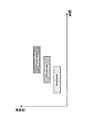
- FIG. 1 is a diagram illustrating an example of A-CSI transmission control.
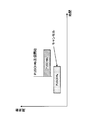
- FIG. 2 is a diagram illustrating an example of UL transmission control in the first mode.
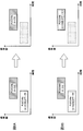
- 3A and 3B are diagrams illustrating another example of UL transmission control in the first mode.
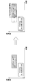
- FIG. 4 is a diagram illustrating an example of UL transmission control in the second mode.
- FIG. 5 is a diagram illustrating another example of UL transmission control in the second mode.
- 6A and 6B are diagrams illustrating another example of UL transmission control in the second mode.
- 7A and 7B are diagrams illustrating another example of UL transmission control in the second mode.
- FIG. 8 is a diagram illustrating an example of UL transmission control in the third mode.
- FIG. 9 is a diagram illustrating an example of a schematic configuration of a wireless communication system according to an embodiment.
- FIG. 10 is a diagram illustrating an example of an overall configuration of a radio base station according to an embodiment.
- FIG. 11 is a diagram illustrating an example of a functional configuration of a radio base station according to an embodiment.
- FIG. 12 is a diagram illustrating an example of the overall configuration of a user terminal according to an embodiment.
- FIG. 13 is a diagram illustrating an example of a functional configuration of a user terminal according to an embodiment.
- FIG. 14 is a diagram illustrating an example of a hardware configuration of a radio base station and a user terminal according to an embodiment.
- a reference signal for measuring the channel state in the downlink is defined.
- the reference signal for channel state measurement is also called CRS (Cell-specific Reference Signal) or CSI-RS (Channel State Information-Reference Signal), CQI (Channel Quality Indicator), PMI (Precoding Matrix Indicator), RI (Rank).
- CRS Cell-specific Reference Signal
- CSI-RS Channel State Information-Reference Signal
- CQI Channel Quality Indicator
- PMI Precoding Matrix Indicator
- RI Rank
- a reference signal used for measurement of channel state information (CSI) such as (Indicator).
- the UE feeds back the measurement result based on the channel state measurement reference signal to the base station as CSI at a predetermined timing.
- Periodic CSI (P-CSI: Periodic CSI) reporting and aperiodic CSI (A-CSI: Aperiodic CSI) reporting are defined as CSI feedback methods.
- the UE When the UE performs P-CSI reporting, the UE performs P-CSI feedback every predetermined period (for example, 5 subframe periods, 10 subframe periods, etc.).
- the UE transmits P-CSI using an uplink control channel of a predetermined cell (for example, primary cell (PCell), PUCCH cell, primary secondary cell (PSCell)).
- a predetermined cell for example, primary cell (PCell), PUCCH cell, primary secondary cell (PSCell)
- the UE When there is no uplink data (for example, PUSCH) transmission at a predetermined timing (predetermined subframe) for reporting P-CSI, the UE transmits P-CSI using an uplink control channel (for example, PUCCH). On the other hand, when there is uplink data transmission at a predetermined timing, the UE can perform P-CSI transmission using the uplink shared channel.
- an uplink control channel for example, PUCCH
- the UE When performing A-CSI reporting, the UE transmits A-CSI in response to a CSI trigger (also referred to as a CSI request) from the base station. For example, the UE performs A-CSI reporting after a predetermined timing (for example, 4 subframes) after receiving the CSI trigger.
- a CSI trigger also referred to as a CSI request
- the UE performs A-CSI reporting after a predetermined timing (for example, 4 subframes) after receiving the CSI trigger.
- the CSI trigger notified from the base station is included in downlink control information (for example, DCI format 0/4) for uplink scheduling grant (UL grant) transmitted using the downlink control channel.
- the UL grant may be DCI that schedules transmission of UL data (for example, PUSCH) and / or UL sounding (for measurement) signals.
- the UE performs A-CSI transmission using the uplink shared channel specified by the UL grant according to the trigger included in the downlink control information for the UL grant. Further, when CA is applied, the UE can receive UL grant (including A-CSI trigger) for a certain cell on the downlink control channel of another cell.
- CSI reporting is controlled using an uplink shared channel (for example, PUSCH) whose allocation is controlled in units of subframes.
- PUSCH uplink shared channel
- CSI reporting is performed using PUSCH whose allocation is controlled in units of OFDM symbols (hereinafter also referred to as symbols).
- a CSI report for example, A-CSI report
- A-CSI report is performed by applying a PUSCH configuration different from that of the existing LTE system
- UL transmission is performed on the base station side.
- How to control the instruction (or trigger) is a problem.
- CA carrier aggregation
- CCs cells
- CA carrier aggregation
- it becomes a problem how the base station controls the number of triggers for A-CSI reporting overlapping with the same symbol.
- the base station side permits the UL transmission instruction that the transmission period overlaps with at least some symbols.
- an instruction for UL transmission in which a transmission period overlaps at least in some symbols is allowed, how to control UL transmission becomes a problem.
- FIG. 1 shows a case where the base station triggers a plurality of A-CSIs whose transmission periods overlap at least with a predetermined symbol.
- A-CSI # 1 and A-CSI # 2 are triggered by different downlink control information (for example, DCI) is shown.
- the base station instructs the UE to transmit A-CSI # 1 and A-CSI # 2 by using PUSCH # 1 and PUSCH # 2 whose transmission periods overlap at least in some symbols.
- the UE When it is allowed to trigger a plurality of A-CSI (or PUSCH) or the like whose transmission periods overlap in at least some symbols in this way (see FIG. 1), the UE is triggered A-CSI or the like.
- the problem is how to control the transmission of.
- the present inventors have studied the presence / absence of a trigger for UL transmission such as A-CSI in which the transmission period overlaps in symbol units and the transmission control of UL transmission, and have come up with a method for appropriately performing the UL transmission.
- overlap indicates that multiple signals and / or channels are transmitted (triggered or scheduled for transmission) in at least some of the same time resources (eg, the same symbol). Note that “overlap” may be read as “collision” or “overlap”.
- the unit of time resource is not limited to symbols, but may be read as slots, minislots, subframes, and the like.
- A-CSI is mainly described as an example of UL transmission, but may be applied to other UL transmissions.
- Other UL transmissions include UL data (or PUSCH) transmission scheduled with downlink control information (for example, DCI), UL data (or PUSCH) transmission not scheduled with DCI, and sounding reference signal (for example, SRS) transmission. There may be.
- SP-CSI refers to CSI reporting using resources specified as semi-persistent (semi-persistent, semi-persistent).
- the first aspect limits UL transmission (for example, A-CSI report) using a predetermined symbol to one in at least a predetermined cell. That is, a plurality of UL transmissions (for example, A-CSI) whose transmission periods overlap in a predetermined symbol are limited, and the trigger is controlled so that UL transmissions do not overlap at the symbol level.
- UL transmission for example, A-CSI report
- A-CSI UL transmissions
- the UE may assume that A-CSI reports triggered by different DCIs do not overlap with the same symbol in a given serving cell. For example, when the A-CSI report is performed using PUSCH, the UE assumes that PUSCH resources to which A-CSI triggered by each DCI is respectively allocated are scheduled to symbols that do not overlap (see FIG. 2). .
- FIG. 2 shows an example in which PUSCH # 1 used for transmission of A-CSI # 1 and PUSCH # 2 used for transmission of A-CSI # 2 are scheduled to different symbols (for example, non-overlapping symbols). Is shown.
- the DCI instructing the trigger of A-CSI # 1 may include PUSCH # 1 scheduling information (for example, PUSCH # 1 resource information).
- the scheduling information of PUSCH # 2 (for example, resource information of PUSCH # 2) may be included in DCI instructing the trigger of A-CSI # 2.
- CA When CA is applied in the UL, at least a part of a plurality of A-CSIs (or a plurality of PUSCHs that multiplex each A-CSI) triggered by different DCIs are provided between different serving cells (or CCs). It is good also as a structure which overlaps with the symbol of.
- the UE may assume that the transmission periods of A-CSI reports triggered by different DCIs do not overlap with the same symbol in at least one of the predetermined PUCCH group and cell group.
- the UE may use multiple A-CSIs (or multiple PUSCHs that multiplex each A-CSI) between multiple CCs included in the same PUCCH group (or cell group). ) Are not duplicated in the same symbol.
- the PUCCH group is a group including a plurality of cells including secondary cells associated with a cell (PCell or PUCCH SCell) that transmits PUCCH.
- the cell group is a group including a master cell group (MCG) including a PCell and a secondary cell group (SCG) including a PSCell when applying dual connectivity (DC).
- MCG master cell group
- SCG secondary cell group
- the transmission period of the A-CSI report is different between cells with different PUCCH groups or cell groups. Can be duplicated with the same symbol.
- A-CSI reporting can be controlled more flexibly.
- a plurality of A-CSI reports triggered by different DCIs may be configured to be performed in the same slot. That is, the transmission period of the plurality of A-CSI reports (or the transmission period of PUSCH used for each A-CSI report) may be controlled so as not to overlap with the same symbol in a predetermined slot (see FIG. 3A).
- A-CSI triggered by DCI # 1 (or scheduled PUSCH # 1) and A-CSI # 2 triggered by DCI # 2 (or scheduled PUSCH # 2) are in the same slot. Sent with different symbols. As described above, by allowing a plurality of UL transmission triggers such as A-CSI using different symbols in the slot, it is possible to suppress delays such as A-CSI reporting.
- a plurality of A-CSI reports triggered by different DCIs may not be performed in the same slot. That is, the transmission period of the plurality of A-CSI reports (or the transmission period of PUSCH used for each A-CSI report) may be controlled so as not to overlap in the same slot (see FIG. 3B).
- FIG. 3B shows a case where only A-CSI triggered by DCI # 1 (or scheduled PUSCH # 1) is transmitted in a predetermined slot. By doing so, it is not necessary to consider the case where a plurality of UL transmissions overlap in a slot, so that transmission processing such as A-CSI can be further simplified.
- the radio base station can appropriately control UL transmission (for example, A-CSI report) using a predetermined symbol based on the reported terminal capability information.
- the second aspect allows multiple UL transmissions (eg, A-CSI reports) using a predetermined symbol to be triggered, while actual UL transmissions (eg, A-CSI report or (PUSCH transmission) is limited to one. That is, the radio base station can trigger a plurality of UL transmissions (for example, A-CSI) whose transmission periods overlap in a predetermined symbol, and the user terminal transmits a part of the overlapping UL transmissions (the remaining To drop or cancel).
- the base station triggers N A-CSI (eg, A-CSI # 1- # 3) reports using PUSCH # 1- # 3.
- the UE controls to select and report a part of the N A-CSI reports (for example, one A-CSI).
- the UE when a plurality of UL transmissions (for example, A-CSI report (or PUSCH transmission in which A-CSI is multiplexed)) transmitted using the same symbol are triggered, the UE performs a transmission based on a predetermined condition. Select the part UL transmission and drop the remaining UL transmission.
- A-CSI report or PUSCH transmission in which A-CSI is multiplexed
- UL transmission is controlled based on a predetermined drop condition or transmission condition of UL transmission (for example, A-CSI or PUSCH).
- a predetermined drop condition or transmission condition of UL transmission for example, A-CSI or PUSCH.
- the first PUSCH transmission and the second PUSCH transmission whose transmission start timing is later than that of the first PUSCH transmission will be described as an example.
- the applicable PUSCH transmission is limited to two. I can't.
- the first PUSCH transmission and the second PUSCH transmission may be replaced with other UL transmissions other than the PUSCH transmission.
- UL transmission to be transmitted or dropped (for example, PUSCH resource used for transmission, A-CSI transmission, UL data, etc.) is determined based on the transmission start timing.
- the second PUSCH transmission (or transmission using the second PUSCH resource) whose transmission start timing is late is given priority over the first PUSCH transmission (or transmission using the first PUSCH resource).
- dropping or canceling a predetermined PUSCH transmission means that the transmission power given to the PUSCH transmission after starting the cancel operation is set to a predetermined level (for example, ⁇ 40 dBm) or less within a predetermined time (for example, 20 us).
- a predetermined level for example, ⁇ 40 dBm
- a predetermined time for example, 20 us.
- Etc. may be defined. In this case, it is possible to avoid continuing the predetermined PUSCH transmission dropped or canceled by the user terminal, and reduce interference.
- the transmission quality (for example, EVM) of the PUSCH transmission is allowed to be a predetermined level or less. In this case, whether to actually stop transmission (or how to stop) depends on the user terminal, so that the cancel operation can be realized by various implementations.
- PUSCH #b is preferentially transmitted.
- the UE drops or cancels the UL signal (for example, at least one of A-CSI and UL data) to be transmitted using the first PUSCH resource (PUSCH #a).
- PUSCH #a including A-CSI report IDs # 1 and # 3 is transmitted using PUSCH #a
- A-CSI including A-CSI report IDs # 2 and # 4 is transmitted using PUSCH #b.
- the base station instructs the UE to transmit #b.
- the UE controls to cancel PUSCH # a and transmit A-CSI # b including A-CSI report ID # 2 and # 4 using PUSCH # b.
- PUSCH transmission for example, A-CSI report
- UL transmission to be transmitted or dropped (for example, PUSCH resource used for transmission, A-CSI transmission, UL data, etc.) is determined based on at least one of transmission start timing and a predetermined priority condition. .
- the second PUSCH transmission (or transmission using the second PUSCH resource) whose transmission start timing is late is transmitted with priority over the first PUSCH transmission (or transmission using the first PUSCH resource).
- the UL signal to be transmitted using the second PUSCH resource is determined based on a predetermined priority condition.
- Priority conditions are UL transmission methods (for example, whether UL transmission is URLLC (Ultra Reliable and Low Latency Communications) or eMBB (enhanced Mobile BroadBBand)), UL signal type, corresponding cell type, each signal It may be determined based on at least one of the index numbers.
- the priority condition may be defined in advance in the specification, or may be notified from the base station to the UE using at least one of higher layer signaling and downlink control information.
- the UL signal to be transmitted may be determined based on the following priority condition #a and priority condition #b.
- the priority condition #b may be considered.
- priority condition #a indicates the priority regarding the UL transmission method
- priority condition #b indicates the priority regarding the UL signal type.
- priority conditions for UL signals having the same signal type may be further defined as priority conditions #b.
- the priority conditions #a and #b are examples and are not limited thereto. The priority order in each priority condition may be changed as appropriate.
- the UL transmission method is not limited to ULRRC and eMBB.
- Priority condition #a The UL signal corresponding to URLLC is prioritized over the UL signal corresponding to eMBB (URLLC> eMBB)
- Priority condition #b A-CSI>A-SRS> UL data
- FIG. 5 A-CSI for URLLC is triggered on one of PUSCH # a or PUSCH # b in FIG. 5 and A-CSI for eMBB is triggered on the other.
- the UE performs an A-CSI report for URLLC using PUSCH #b (second PUSCH resource) based on the priority condition #a, and controls to drop the A-CSI for eMBB. May be.
- the priority conditions for UL signals with the same signal type are determined based on at least one of the time domain operation method of A-CSI, the contents of A-CSI, the cell iD to which A-CSI corresponds, and the CSI report ID. Also good.
- the CSI to be transmitted may be determined based on the following priority conditions # b1- # b4. In this case, priority conditions # b-1 to # b-4 are preferentially applied.
- Priority condition # b-1 Time domain operation (A-CSI> SP-CSI using PUSCH>SP-CSI>PUCCH> P-CSI)
- Priority condition # b-2 CSI content (beam report> CSI)
- Priority condition # b-3 Cell ID (PCell>PSCell> SCell (SCell having a smaller index))
- Priority condition # b-4 CSI report ID (CSI report ID with a smaller index)
- A-CSI report IDs # 1 and # 3 including A-CSI report IDs # 1 and # 3 are transmitted using PUSCH #a
- A-CSI report IDs # 2 and # 4 are transmitted using PUSCH #b.
- the base station instructs the UE to transmit A-CSI # b including When priority conditions # b-1 to # b-3 are the same between A-CSI #a and A-CSI #b, A-CSI to be transmitted is determined based on priority condition # b-4.
- the UE reports A-CSI report ID # 1 and A-CSI report ID # 2 using PUSCH # b (second PUSCH resource).
- the PUSCH resource to be transmitted and the UL signal can be appropriately determined and transmitted.
- FIG. 6 shows a case where A-CSI # a and UL data using PUSCH # a are triggered or scheduled, and A-CSI # b using PUSCH # b is triggered.
- A-CSI transmission of A-CSI is prioritized over UL data (when the UL transmission method is the same and priority condition # 2 is applied).
- control is performed such that A-CSI is selectively transmitted (UL data is not transmitted) using PUSCH #b (second PUSCH resource) (see FIG. 6A).
- the A-CSI transmitted by PUSCH # b may be A-CSI # b triggered in advance for PUSCH # b.
- the A-CSI to be transmitted may be determined based on the above-described priority conditions # b-1 to # b-4.
- A-CSI #b For example, A-CSI #b
- UL data applies URLLC
- A-CSI #b applies eMBB
- priority condition # 1 is set. If applicable.
- control is performed such that UL data is transmitted with priority over A-CSI # b using PUSCH # b (second PUSCH resource) (see FIG. 6B).
- the A-CSI transmitted on the PUSCH #b may be the A-CSI #a triggered for the PUSCH #a as with the UL data.
- only UL data may be transmitted and A-CSI may not be transmitted.
- UL data to be actually transmitted is determined based on the UL transmission method. For example, if one is URLLC UL data and the other is eMBB UL data, the URLLC UL data is transmitted using a predetermined PUSCH resource (for example, the second PUSCH resource).
- the UE first considers the transmission method applied to A-SRS and the transmission method (priority condition #a) applied to A-CSI and UL data. For example, when URLLC is applied to A-CSI and UL data and eMBB is applied to A-SRS, the UE controls to transmit A-CSI and UL data with priority and drop A-SRS. .
- the UE determines the UL signal to be transmitted based on the priority of the UL signal type (priority condition #b). To do.
- the priority condition #b is A-CSI> A-SRS> UL data
- the UE transmits at least A-CSI.
- UL data scheduled on the same PUSCH as A-CSI may be transmitted and A-SRS may be dropped. Alternatively, it may be controlled to drop UL data and transmit A-CSI and A-SRS. Alternatively, it may be controlled to drop UL data and A-SRS and transmit only A-CSI. Whether or not to transmit at least one of UL data and A-SRS may be determined based on the capacity of a PUSCH resource (for example, PUSCH # b) used for transmission.
- PUSCH resource for example, PUSCH # b
- the second PUSCH resource (PUSCH # b) whose transmission start timing is late when PUSCH transmission (for example, A-CSI report) whose transmission periods overlap at least in some symbols is triggered.
- PUSCH transmission for example, A-CSI report
- FIG. 7 the first PUSCH resource (PUSCH #a) with early transmission start timing may be used.
- the first PUSCH resource (PUSCH # a) may be used as shown in FIGS. 7A and 7B. Good.
- PUSCH transmission for example, A-CSI report
- it is not based on the transmission start timing but based on other parameters (for example, the length of the transmission period, etc.)
- You may select the PUSCH resource utilized for UL transmission.
- the PUSCH resource used for transmission may be selected based on the UL signal (for example, at least one of A-CSI and UL data) to be actually transmitted.
- a PUSCH resource for example, PUSCH # a in FIG. 6 on which UL data is scheduled is a resource (for example, PRB) allocated from a PUSCH resource (for example, PUSCH # b in FIG. 6) in which only A-CSI is triggered. ) Increase the number.
- the UE when transmitting UL data based on a predetermined priority condition, the UE controls to perform UL transmission using a PUSCH resource (PUSCH #a in FIG. 6) on which the UL data is scheduled. May be.
- PUSCH #a PUSCH resource
- the PUSCH resource allocated for UL transmission for example, UL data
- problems such as a shortage of PUSCH resources can be avoided.
- the UE may control the A-CSI multiplexed on the predetermined PUSCH based on the coding rate determined by the resource amount allocated to the predetermined PUSCH.
- the plurality of A-CSIs are multiplexed on the predetermined PUSCH. May be transmitted.
- more A-CSI and the like can be transmitted based on PUSCH resources and the like used for UL transmission, so that resource utilization efficiency can be improved.
- FIG. 8 shows a case where transmission using the first PUSCH resource (PUSCH # a) and transmission using the second PUSCH resource (PUSCH # b) that overlap in at least some symbols are triggered or scheduled. The case where it shifts so that PUSCH # a and PUSCH # b do not overlap is shown.
- FIG. 8 shows a case where shifting is performed so that PUSCH # b is transmitted continuously following PUSCH # a (when the next symbol after the last symbol of PUSCH # a becomes the start symbol of PUSCH # b). . Thereby, the influence of the delay of PUSCH # b can be minimized.
- the PUSCH #b may be shifted so as to be transmitted in subsequent predetermined slots.
- the predetermined slot may be a slot having a time interval designated and set as UL in UL-DL assignment specified by UL-DL assignment or slot format notification (SFI) determined by higher layer signaling.
- SFI slot format notification
- the transmission start symbol of PUSCH #b in the slot may be the same as the start symbol initially specified by DCI. Thereby, the transmission timing of PUSCH # b can be flexibly controlled.
- wireless communication system Wireless communication system
- communication is performed using any one or a combination of the wireless communication methods according to the above-described embodiments of the present disclosure.
- FIG. 9 is a diagram illustrating an example of a schematic configuration of a wireless communication system according to an embodiment.
- carrier aggregation (CA) and / or dual connectivity (DC) in which a plurality of basic frequency blocks (component carriers) each having a system bandwidth (for example, 20 MHz) of the LTE system as one unit are applied. can do.
- DC dual connectivity
- the wireless communication system 1 includes LTE (Long Term Evolution), LTE-A (LTE-Advanced), LTE-B (LTE-Beyond), SUPER 3G, IMT-Advanced 4G (4th generation mobile communication system), 5G. (5th generation mobile communication system), NR (New Radio), FRA (Future Radio Access), New-RAT (Radio Access Technology), etc., or a system that realizes these.
- the radio communication system 1 includes a radio base station 11 that forms a macro cell C1 having a relatively wide coverage, and a radio base station 12 (12a-12c) that is arranged in the macro cell C1 and forms a small cell C2 that is narrower than the macro cell C1. It is equipped with. Moreover, the user terminal 20 is arrange
- the user terminal 20 can be connected to both the radio base station 11 and the radio base station 12. It is assumed that the user terminal 20 uses the macro cell C1 and the small cell C2 at the same time using CA or DC. Moreover, the user terminal 20 may apply CA or DC using a plurality of cells (CC).
- CC a plurality of cells
- Communication between the user terminal 20 and the radio base station 11 can be performed using a carrier having a relatively low frequency band (for example, 2 GHz) and a narrow bandwidth (also referred to as an existing carrier or a legacy carrier).
- a carrier having a relatively high frequency band for example, 3.5 GHz, 5 GHz, etc.
- the same carrier may be used.
- the configuration of the frequency band used by each radio base station is not limited to this.
- the user terminal 20 can perform communication using time division duplex (TDD) and / or frequency division duplex (FDD) in each cell.
- TDD time division duplex
- FDD frequency division duplex
- a single neurology may be applied, or a plurality of different neurology may be applied.
- Numerology may be a communication parameter applied to transmission and / or reception of a certain signal and / or channel, for example, subcarrier interval, bandwidth, symbol length, cyclic prefix length, subframe length. , TTI length, number of symbols per TTI, radio frame configuration, specific filtering process performed by the transceiver in the frequency domain, specific windowing process performed by the transceiver in the time domain, and the like.
- subcarrier interval bandwidth, symbol length, cyclic prefix length, subframe length.
- TTI length number of symbols per TTI
- radio frame configuration specific filtering process performed by the transceiver in the frequency domain
- specific windowing process performed by the transceiver in the time domain and the like.
- the wireless base station 11 and the wireless base station 12 are connected by wire (for example, optical fiber compliant with CPRI (Common Public Radio Interface), X2 interface, etc.) or wirelessly. May be.
- the radio base station 11 and each radio base station 12 are connected to the higher station apparatus 30 and connected to the core network 40 via the higher station apparatus 30.
- the upper station device 30 includes, for example, an access gateway device, a radio network controller (RNC), a mobility management entity (MME), and the like, but is not limited thereto.
- RNC radio network controller
- MME mobility management entity
- Each radio base station 12 may be connected to the higher station apparatus 30 via the radio base station 11.
- the radio base station 11 is a radio base station having a relatively wide coverage, and may be called a macro base station, an aggregation node, an eNB (eNodeB), a transmission / reception point, or the like.
- the radio base station 12 is a radio base station having local coverage, and includes a small base station, a micro base station, a pico base station, a femto base station, a HeNB (Home eNodeB), an RRH (Remote Radio Head), and transmission / reception. It may be called a point.
- the radio base stations 11 and 12 are not distinguished, they are collectively referred to as a radio base station 10.
- Each user terminal 20 is a terminal that supports various communication schemes such as LTE and LTE-A, and may include not only a mobile communication terminal (mobile station) but also a fixed communication terminal (fixed station).
- orthogonal frequency division multiple access (OFDMA) is applied to the downlink, and single carrier-frequency division multiple access (SC-FDMA) is used for the uplink.
- SC-FDMA single carrier-frequency division multiple access
- Frequency Division Multiple Access and / or OFDMA is applied.
- OFDMA is a multi-carrier transmission scheme that performs communication by dividing a frequency band into a plurality of narrow frequency bands (subcarriers) and mapping data to each subcarrier.
- SC-FDMA is a single carrier transmission in which the system bandwidth is divided into bands each composed of one or continuous resource blocks for each terminal, and a plurality of terminals use different bands to reduce interference between terminals. It is a method.
- the uplink and downlink radio access schemes are not limited to these combinations, and other radio access schemes may be used.
- downlink channels include a downlink shared channel (PDSCH) shared by each user terminal 20, a broadcast channel (PBCH: Physical Broadcast Channel), a downlink L1 / L2 control channel, and the like. Used. User data, higher layer control information, SIB (System Information Block), etc. are transmitted by PDSCH. Moreover, MIB (Master Information Block) is transmitted by PBCH.
- PDSCH downlink shared channel
- PBCH Physical Broadcast Channel
- SIB System Information Block
- MIB Master Information Block
- Downlink L1 / L2 control channels include PDCCH (Physical Downlink Control Channel), EPDCCH (Enhanced Physical Downlink Control Channel), PCFICH (Physical Control Format Indicator Channel), PHICH (Physical Hybrid-ARQ Indicator Channel), and the like.
- Downlink control information (DCI: Downlink Control Information) including PDSCH and / or PUSCH scheduling information is transmitted by the PDCCH.
- scheduling information may be notified by DCI.
- DCI for scheduling DL data reception may be referred to as DL assignment
- DCI for scheduling UL data transmission may be referred to as UL grant.
- the number of OFDM symbols used for PDCCH is transmitted by PCFICH.
- the PHICH transmits HARQ (Hybrid Automatic Repeat reQuest) delivery confirmation information (for example, retransmission control information, HARQ-ACK, ACK / NACK, etc.) to the PUSCH.
- HARQ Hybrid Automatic Repeat reQuest
- EPDCCH is frequency-division multiplexed with PDSCH (downlink shared data channel), and is used for transmission of DCI and the like in the same manner as PDCCH.
- an uplink shared channel (PUSCH) shared by each user terminal 20
- an uplink control channel (PUCCH: Physical Uplink Control Channel)
- a random access channel (PRACH: Physical Random Access Channel)
- User data, higher layer control information, etc. are transmitted by PUSCH.
- downlink radio quality information CQI: Channel Quality Indicator
- delivery confirmation information SR
- scheduling request etc.
- a random access preamble for establishing connection with the cell is transmitted by the PRACH.
- a cell-specific reference signal CRS
- CSI-RS channel state information reference signal
- DMRS demodulation reference signal
- PRS Positioning Reference Signal
- a measurement reference signal SRS: Sounding Reference Signal
- a demodulation reference signal DMRS
- the DMRS may be referred to as a user terminal specific reference signal (UE-specific Reference Signal). Further, the transmitted reference signal is not limited to these.
- FIG. 10 is a diagram illustrating an example of an overall configuration of a radio base station according to an embodiment.
- the radio base station 10 includes a plurality of transmission / reception antennas 101, an amplifier unit 102, a transmission / reception unit 103, a baseband signal processing unit 104, a call processing unit 105, and a transmission path interface 106.
- the transmission / reception antenna 101, the amplifier unit 102, and the transmission / reception unit 103 may each be configured to include one or more.
- User data transmitted from the radio base station 10 to the user terminal 20 via the downlink is input from the higher station apparatus 30 to the baseband signal processing unit 104 via the transmission path interface 106.
- PDCP Packet Data Convergence Protocol
- RLC Radio Link Control
- MAC Medium Access
- Retransmission control for example, HARQ transmission processing
- scheduling transmission format selection, channel coding, Inverse Fast Fourier Transform (IFFT) processing, precoding processing, and other transmission processing
- IFFT Inverse Fast Fourier Transform
- precoding processing precoding processing, and other transmission processing
- the downlink control signal is also subjected to transmission processing such as channel coding and inverse fast Fourier transform, and is transferred to the transmission / reception unit 103.
- the transmission / reception unit 103 converts the baseband signal output by precoding for each antenna from the baseband signal processing unit 104 to a radio frequency band and transmits the converted signal.
- the radio frequency signal frequency-converted by the transmission / reception unit 103 is amplified by the amplifier unit 102 and transmitted from the transmission / reception antenna 101.
- the transmission / reception unit 103 can be configured by a transmitter / receiver, a transmission / reception circuit, or a transmission / reception device described based on common recognition in the technical field according to the present disclosure.
- the transmission / reception part 103 may be comprised as an integral transmission / reception part, and may be comprised from a transmission part and a receiving part.
- the radio frequency signal received by the transmission / reception antenna 101 is amplified by the amplifier unit 102.
- the transmission / reception unit 103 receives the uplink signal amplified by the amplifier unit 102.
- the transmission / reception unit 103 converts the frequency of the received signal into a baseband signal and outputs it to the baseband signal processing unit 104.
- the baseband signal processing unit 104 performs fast Fourier transform (FFT) processing, inverse discrete Fourier transform (IDFT: Inverse Discrete Fourier Transform) processing, and error correction on user data included in the input upstream signal.
- FFT fast Fourier transform
- IDFT inverse discrete Fourier transform
- Decoding, MAC retransmission control reception processing, RLC layer and PDCP layer reception processing are performed and transferred to the upper station apparatus 30 via the transmission path interface 106.
- the call processor 105 performs communication channel call processing (setting, release, etc.), status management of the radio base station 10, radio resource management, and the like.
- the transmission path interface 106 transmits and receives signals to and from the higher station apparatus 30 via a predetermined interface.
- the transmission path interface 106 transmits / receives signals (backhaul signaling) to / from other radio base stations 10 via an interface between base stations (for example, an optical fiber compliant with CPRI (Common Public Radio Interface), X2 interface). May be.
- CPRI Common Public Radio Interface
- X2 interface May be.
- the transmission / reception unit 103 may receive channel state information (for example, A-CSI) transmitted from the user terminal 20 using a resource specified by DCI.
- the transmission / reception unit 103 may transmit a CSI transmission instruction (trigger or UL grant) to the user terminal 20. Further, the transmission / reception unit 103 may transmit information on the priority of the A-CSI report to the user terminal 20.
- FIG. 11 is a diagram illustrating an example of a functional configuration of a radio base station according to an embodiment of the present disclosure.
- the functional block of the characteristic part in this embodiment is mainly shown, and it may be assumed that the wireless base station 10 also has other functional blocks necessary for wireless communication.
- the baseband signal processing unit 104 includes at least a control unit (scheduler) 301, a transmission signal generation unit 302, a mapping unit 303, a reception signal processing unit 304, and a measurement unit 305. These configurations may be included in the radio base station 10, and a part or all of the configurations may not be included in the baseband signal processing unit 104.
- the control unit (scheduler) 301 controls the entire radio base station 10.
- the control unit 301 can be configured by a controller, a control circuit, or a control device described based on common recognition in the technical field according to the present disclosure.
- the control unit 301 controls, for example, signal generation in the transmission signal generation unit 302, signal allocation in the mapping unit 303, and the like.
- the control unit 301 also controls signal reception processing in the reception signal processing unit 304, signal measurement in the measurement unit 305, and the like.
- the control unit 301 schedules system information, downlink data signals (for example, signals transmitted by PDSCH), downlink control signals (for example, signals transmitted by PDCCH and / or EPDCCH, delivery confirmation information, etc.) (for example, resource Control). In addition, the control unit 301 controls generation of a downlink control signal, a downlink data signal, and the like based on a result of determining whether or not retransmission control is necessary for the uplink data signal.
- downlink data signals for example, signals transmitted by PDSCH
- downlink control signals for example, signals transmitted by PDCCH and / or EPDCCH, delivery confirmation information, etc.
- resource Control for example, resource Control
- the control unit 301 controls scheduling of synchronization signals (for example, PSS (Primary Synchronization Signal) / SSS (Secondary Synchronization Signal)), downlink reference signals (for example, CRS, CSI-RS, DMRS).
- synchronization signals for example, PSS (Primary Synchronization Signal) / SSS (Secondary Synchronization Signal)
- downlink reference signals for example, CRS, CSI-RS, DMRS.
- the control unit 301 includes an uplink data signal (for example, a signal transmitted by PUSCH), an uplink control signal (for example, a signal transmitted by PUCCH and / or PUSCH, delivery confirmation information, etc.), a random access preamble (for example, by PRACH). (Sending signal), scheduling of uplink reference signals and the like are controlled.
- an uplink data signal for example, a signal transmitted by PUSCH
- an uplink control signal for example, a signal transmitted by PUCCH and / or PUSCH, delivery confirmation information, etc.
- a random access preamble for example, by PRACH.
- the control unit 301 may perform control so that transmission periods of a plurality of UL signals (for example, A-CSI) do not overlap with the same symbol. Further, it may be controlled such that the transmission periods of a plurality of UL signals instructing transmission based on different downlink control information are set to different symbols in the same slot, or the transmission periods of the plurality of UL signals are within the same slot. You may control so that it is not set to.
- a plurality of UL signals for example, A-CSI
- the transmission signal generation unit 302 generates a downlink signal (downlink control signal, downlink data signal, downlink reference signal, etc.) based on an instruction from the control unit 301, and outputs it to the mapping unit 303.
- the transmission signal generation unit 302 can be configured by a signal generator, a signal generation circuit, or a signal generation device described based on common recognition in the technical field according to the present disclosure.
- the transmission signal generation unit 302 generates, for example, a DL assignment for notifying downlink data allocation information and / or a UL grant for notifying uplink data allocation information based on an instruction from the control unit 301.
- the DL assignment and UL grant are both DCI and follow the DCI format.
- the downlink data signal is subjected to coding processing and modulation processing according to a coding rate, a modulation scheme, and the like determined based on channel state information (CSI: Channel State Information) from each user terminal 20.
- CSI Channel State Information
- the mapping unit 303 maps the downlink signal generated by the transmission signal generation unit 302 to a predetermined radio resource based on an instruction from the control unit 301, and outputs it to the transmission / reception unit 103.
- the mapping unit 303 can be configured by a mapper, a mapping circuit, or a mapping device described based on common recognition in the technical field according to the present disclosure.
- the reception signal processing unit 304 performs reception processing (for example, demapping, demodulation, decoding, etc.) on the reception signal input from the transmission / reception unit 103.
- the received signal is, for example, an uplink signal (uplink control signal, uplink data signal, uplink reference signal, etc.) transmitted from the user terminal 20.
- the reception signal processing unit 304 can be configured by a signal processor, a signal processing circuit, or a signal processing device described based on common recognition in the technical field according to the present disclosure.
- the reception signal processing unit 304 outputs the information decoded by the reception processing to the control unit 301. For example, when receiving PUCCH including HARQ-ACK, HARQ-ACK is output to control section 301.
- the reception signal processing unit 304 outputs the reception signal and / or the signal after reception processing to the measurement unit 305.
- the measurement unit 305 performs measurement on the received signal.
- the measurement unit 305 can be configured from a measurement device, a measurement circuit, or a measurement device described based on common recognition in the technical field according to the present disclosure.
- the measurement unit 305 may perform RRM (Radio Resource Management) measurement, CSI (Channel State Information) measurement, and the like based on the received signal.
- the measurement unit 305 includes received power (for example, RSRP (Reference Signal Received Power)), received quality (for example, RSRQ (Reference Signal Received Quality), SINR (Signal to Interference plus Noise Ratio), SNR (Signal to Noise Ratio)).
- Signal strength for example, RSSI (Received Signal Strength Indicator)
- propagation path information for example, CSI
- the measurement result may be output to the control unit 301.
- FIG. 12 is a diagram illustrating an example of the overall configuration of a user terminal according to an embodiment.
- the user terminal 20 includes a plurality of transmission / reception antennas 201, an amplifier unit 202, a transmission / reception unit 203, a baseband signal processing unit 204, and an application unit 205.
- the transmission / reception antenna 201, the amplifier unit 202, and the transmission / reception unit 203 may each be configured to include one or more.
- the radio frequency signal received by the transmission / reception antenna 201 is amplified by the amplifier unit 202.
- the transmission / reception unit 203 receives the downlink signal amplified by the amplifier unit 202.
- the transmission / reception unit 203 converts the frequency of the received signal into a baseband signal and outputs it to the baseband signal processing unit 204.
- the transmission / reception unit 203 can be configured by a transmitter / receiver, a transmission / reception circuit, or a transmission / reception device described based on common recognition in the technical field according to the present disclosure.
- the transmission / reception unit 203 may be configured as an integral transmission / reception unit, or may be configured from a transmission unit and a reception unit.
- the baseband signal processing unit 204 performs FFT processing, error correction decoding, retransmission control reception processing, and the like on the input baseband signal.
- the downlink user data is transferred to the application unit 205.
- the application unit 205 performs processing related to layers higher than the physical layer and the MAC layer. Also, broadcast information of downlink data may be transferred to the application unit 205.
- uplink user data is input from the application unit 205 to the baseband signal processing unit 204.
- the baseband signal processing unit 204 performs transmission / reception units for retransmission control (for example, HARQ transmission processing), channel coding, precoding, discrete Fourier transform (DFT) processing, IFFT processing, and the like. 203.
- the transmission / reception unit 203 converts the baseband signal output from the baseband signal processing unit 204 into a radio frequency band and transmits it.
- the radio frequency signal frequency-converted by the transmission / reception unit 203 is amplified by the amplifier unit 202 and transmitted from the transmission / reception antenna 201.
- the transmission / reception unit 203 transmits one or more UL signals using an uplink shared channel based on an instruction from the base station.
- the transmission / reception unit 203 may receive a CSI transmission instruction (trigger or UL grant). Further, the transmission / reception unit 203 may receive information on the priority of the A-CSI report.
- FIG. 13 is a diagram illustrating an example of a functional configuration of a user terminal according to an embodiment.
- the functional block of the characteristic part in this embodiment is mainly shown, and it may be assumed that the user terminal 20 also has other functional blocks necessary for wireless communication.
- the baseband signal processing unit 204 included in the user terminal 20 includes at least a control unit 401, a transmission signal generation unit 402, a mapping unit 403, a reception signal processing unit 404, and a measurement unit 405. Note that these configurations may be included in the user terminal 20, and some or all of the configurations may not be included in the baseband signal processing unit 204.
- the control unit 401 controls the entire user terminal 20.
- the control unit 401 can be configured by a controller, a control circuit, or a control device described based on common recognition in the technical field according to the present disclosure.
- the control unit 401 controls, for example, signal generation in the transmission signal generation unit 402, signal allocation in the mapping unit 403, and the like.
- the control unit 401 also controls signal reception processing in the reception signal processing unit 404, signal measurement in the measurement unit 405, and the like.
- the control unit 401 acquires the downlink control signal and the downlink data signal transmitted from the radio base station 10 from the reception signal processing unit 404.
- the control unit 401 controls the generation of the uplink control signal and / or the uplink data signal based on the result of determining the necessity of retransmission control for the downlink control signal and / or the downlink data signal.
- the control unit 401 may control transmission assuming that the transmission periods of a plurality of UL signals do not overlap with the same symbol. In this case, the control unit 401 may assume that transmission periods of the plurality of UL signals instructed to be transmitted based on different downlink control information may be set to different symbols in the same slot.
- control unit 401 may control to select and transmit some UL signals when at least some of the transmission periods of a plurality of UL signals overlap with the same symbol. For example, when a plurality of uplink shared channels are scheduled for transmission of a plurality of UL signals, the control unit 401 controls to transmit some UL signals using an uplink shared channel whose transmission start timing is late. May be.
- the control unit 401 may determine the partial UL signal based on at least one of a UL transmission scheme, a UL signal type, a cell type corresponding to the UL transmission, and an UL signal index number.
- control part 401 does not overlap the transmission period of a some uplink shared channel, when at least one part of the transmission period of the some uplink shared channel scheduled for transmission of a some UL signal overlaps with the same symbol.
- the transmission start timing of at least one uplink shared channel may be controlled to be shifted.
- control unit 401 may update parameters used for control based on the information.
- the transmission signal generation unit 402 generates an uplink signal (uplink control signal, uplink data signal, uplink reference signal, etc.) based on an instruction from the control unit 401 and outputs the uplink signal to the mapping unit 403.
- the transmission signal generation unit 402 can be configured by a signal generator, a signal generation circuit, or a signal generation device described based on common recognition in the technical field according to the present disclosure.
- the transmission signal generation unit 402 generates an uplink control signal related to delivery confirmation information, channel state information (CSI), and the like based on an instruction from the control unit 401, for example. In addition, the transmission signal generation unit 402 generates an uplink data signal based on an instruction from the control unit 401. For example, the transmission signal generation unit 402 is instructed by the control unit 401 to generate an uplink data signal when the UL grant is included in the downlink control signal notified from the radio base station 10.
- CSI channel state information
- the mapping unit 403 maps the uplink signal generated by the transmission signal generation unit 402 to a radio resource based on an instruction from the control unit 401, and outputs the radio signal to the transmission / reception unit 203.
- the mapping unit 403 can be configured by a mapper, a mapping circuit, or a mapping device described based on common recognition in the technical field according to the present disclosure.
- the reception signal processing unit 404 performs reception processing (for example, demapping, demodulation, decoding, etc.) on the reception signal input from the transmission / reception unit 203.
- the received signal is, for example, a downlink signal (downlink control signal, downlink data signal, downlink reference signal, etc.) transmitted from the radio base station 10.
- the reception signal processing unit 404 can be configured by a signal processor, a signal processing circuit, or a signal processing device described based on common recognition in the technical field according to the present disclosure. Further, the reception signal processing unit 404 can constitute a reception unit according to the present disclosure.
- the reception signal processing unit 404 outputs the information decoded by the reception processing to the control unit 401.
- the reception signal processing unit 404 outputs, for example, broadcast information, system information, RRC signaling, DCI, and the like to the control unit 401.
- the reception signal processing unit 404 outputs the reception signal and / or the signal after reception processing to the measurement unit 405.
- the measurement unit 405 performs measurement on the received signal.
- the measurement unit 405 can be configured from a measurement device, a measurement circuit, or a measurement device described based on common recognition in the technical field according to the present disclosure.
- the measurement unit 405 may perform RRM measurement, CSI measurement, and the like based on the received signal.
- the measurement unit 405 may measure reception power (for example, RSRP), reception quality (for example, RSRQ, SINR, SNR), signal strength (for example, RSSI), propagation path information (for example, CSI), and the like.
- the measurement result may be output to the control unit 401.
- each functional block (components) are realized by any combination of hardware and / or software.
- the method for realizing each functional block is not particularly limited. That is, each functional block may be realized using one device physically and / or logically coupled, or directly and / or two or more devices physically and / or logically separated. Alternatively, it may be realized indirectly by connecting (for example, using wired and / or wireless) and using these plural devices.
- a wireless base station, a user terminal, and the like may function as a computer that performs processing of the wireless communication method of the present disclosure.
- FIG. 14 is a diagram illustrating an example of a hardware configuration of a radio base station and a user terminal according to an embodiment.
- the wireless base station 10 and the user terminal 20 described above may be physically configured as a computer device including a processor 1001, a memory 1002, a storage 1003, a communication device 1004, an input device 1005, an output device 1006, a bus 1007, and the like. Good.
- the term “apparatus” can be read as a circuit, a device, a unit, or the like.
- the hardware configurations of the radio base station 10 and the user terminal 20 may be configured to include one or a plurality of each device illustrated in the figure, or may be configured not to include some devices.
- processor 1001 may be implemented by one or more chips.
- Each function in the radio base station 10 and the user terminal 20 is calculated by causing the processor 1001 to perform calculations by reading predetermined software (programs) on hardware such as the processor 1001 and the memory 1002, for example, via the communication device 1004. This is realized by controlling communication and controlling reading and / or writing of data in the memory 1002 and the storage 1003.
- the processor 1001 controls the entire computer by operating an operating system, for example.
- the processor 1001 may be configured by a central processing unit (CPU) including an interface with peripheral devices, a control device, an arithmetic device, a register, and the like.
- CPU central processing unit
- the baseband signal processing unit 104 (204) and the call processing unit 105 described above may be realized by the processor 1001.
- the processor 1001 reads programs (program codes), software modules, data, and the like from the storage 1003 and / or the communication device 1004 to the memory 1002, and executes various processes according to these.
- programs program codes
- software modules software modules
- data data
- the control unit 401 of the user terminal 20 may be realized by a control program stored in the memory 1002 and operating in the processor 1001, and may be realized similarly for other functional blocks.
- the memory 1002 is a computer-readable recording medium such as a ROM (Read Only Memory), an EPROM (Erasable Programmable ROM), an EEPROM (Electrically EPROM), a RAM (Random Access Memory), or any other suitable storage medium. It may be configured by one.
- the memory 1002 may be called a register, a cache, a main memory (main storage device), or the like.
- the memory 1002 can store a program (program code), a software module, and the like that can be executed to implement the wireless communication method according to an embodiment.
- the storage 1003 is a computer-readable recording medium such as a flexible disk, a floppy (registered trademark) disk, a magneto-optical disk (for example, a compact disk (CD-ROM (Compact Disc ROM)), a digital versatile disk, Blu-ray® disk), removable disk, hard disk drive, smart card, flash memory device (eg, card, stick, key drive), magnetic stripe, database, server, or other suitable storage medium It may be constituted by.
- the storage 1003 may be referred to as an auxiliary storage device.
- the communication device 1004 is hardware (transmission / reception device) for performing communication between computers via a wired and / or wireless network, and is also referred to as a network device, a network controller, a network card, a communication module, or the like.
- the communication device 1004 includes, for example, a high-frequency switch, a duplexer, a filter, a frequency synthesizer, etc., in order to realize frequency division duplex (FDD) and / or time division duplex (TDD). It may be configured.
- FDD frequency division duplex
- TDD time division duplex
- the transmission / reception antenna 101 (201), the amplifier unit 102 (202), the transmission / reception unit 103 (203), the transmission path interface 106, and the like described above may be realized by the communication device 1004.
- the input device 1005 is an input device (for example, a keyboard, a mouse, a microphone, a switch, a button, a sensor, etc.) that accepts an input from the outside.
- the output device 1006 is an output device (for example, a display, a speaker, an LED (Light Emitting Diode) lamp, etc.) that performs output to the outside.
- the input device 1005 and the output device 1006 may have an integrated configuration (for example, a touch panel).
- the devices such as the processor 1001 and the memory 1002 are connected by a bus 1007 for communicating information.
- the bus 1007 may be configured using a single bus, or may be configured using a different bus for each device.
- the radio base station 10 and the user terminal 20 include a microprocessor, a digital signal processor (DSP), an ASIC (Application Specific Integrated Circuit), a PLD (Programmable Logic Device), an FPGA (Field Programmable Gate Array), and the like. It may be configured including hardware, and a part or all of each functional block may be realized using the hardware. For example, the processor 1001 may be implemented using at least one of these hardware.
- DSP digital signal processor
- ASIC Application Specific Integrated Circuit
- PLD Programmable Logic Device
- FPGA Field Programmable Gate Array
- the channel and / or symbol may be a signal (signaling).
- the signal may be a message.
- the reference signal may be abbreviated as RS (Reference Signal), and may be referred to as a pilot, a pilot signal, or the like depending on an applied standard.
- a component carrier CC: Component Carrier
- CC Component Carrier
- the radio frame may be configured by one or a plurality of periods (frames) in the time domain.
- Each of the one or more periods (frames) constituting the radio frame may be referred to as a subframe.
- a subframe may be composed of one or more slots in the time domain.
- the subframe may have a fixed time length (eg, 1 ms) that does not depend on the neurology.
- the slot may be configured by one or a plurality of symbols (OFDM (Orthogonal Frequency Division Multiplexing) symbol, SC-FDMA (Single Carrier Frequency Division Multiple Access) symbol, etc.) in the time domain.
- the slot may be a time unit based on the numerology.
- the slot may include a plurality of mini slots. Each minislot may be configured with one or more symbols in the time domain. The minislot may also be called a subslot.
- Radio frame, subframe, slot, minislot, and symbol all represent time units when transmitting signals. Different names may be used for the radio frame, subframe, slot, minislot, and symbol.
- one subframe may be called a transmission time interval (TTI)
- TTI transmission time interval
- a plurality of consecutive subframes may be called a TTI
- TTI slot or one minislot
- a unit representing TTI may be called a slot, a minislot, or the like instead of a subframe.
- TTI means, for example, a minimum time unit for scheduling in wireless communication.
- a radio base station performs scheduling for assigning radio resources (frequency bandwidth, transmission power, etc. that can be used in each user terminal) to each user terminal in units of TTI.
- the definition of TTI is not limited to this.
- the TTI may be a transmission time unit of a channel-encoded data packet (transport block), a code block, and / or a code word, or may be a processing unit such as scheduling or link adaptation.
- a time interval for example, the number of symbols
- a transport block, a code block, and / or a code word is actually mapped may be shorter than the TTI.
- one or more TTIs may be the minimum scheduling unit. Further, the number of slots (the number of mini-slots) constituting the minimum time unit of the scheduling may be controlled.
- a TTI having a time length of 1 ms may be called a normal TTI (TTI in LTE Rel. 8-12), a normal TTI, a long TTI, a normal subframe, a normal subframe, or a long subframe.
- a TTI shorter than a normal TTI may be called a shortened TTI, a short TTI, a partial TTI (partial or fractional TTI), a shortened subframe, a short subframe, a minislot, or a subslot.
- a long TTI (eg, normal TTI, subframe, etc.) may be read as a TTI having a time length exceeding 1 ms, and a short TTI (eg, shortened TTI) is less than the TTI length of the long TTI and 1 ms. It may be replaced with a TTI having the above TTI length.
- a resource block is a resource allocation unit in the time domain and the frequency domain, and may include one or a plurality of continuous subcarriers (subcarriers) in the frequency domain. Further, the RB may include one or a plurality of symbols in the time domain, and may have a length of 1 slot, 1 mini slot, 1 subframe, or 1 TTI. One TTI and one subframe may each be composed of one or a plurality of resource blocks.
- One or more RBs include physical resource blocks (PRB), sub-carrier groups (SCG), resource element groups (REG), PRB pairs, RB pairs, etc. May be called.
- the resource block may be configured by one or a plurality of resource elements (RE: Resource Element).
- RE Resource Element
- 1RE may be a radio resource region of 1 subcarrier and 1 symbol.
- the structure of the above-described radio frame, subframe, slot, minislot, symbol, etc. is merely an example.
- the number of subframes included in a radio frame, the number of slots per subframe or radio frame, the number of minislots included in the slot, the number of symbols and RBs included in the slot or minislot, and the RB The number of subcarriers, the number of symbols in the TTI, the symbol length, the cyclic prefix (CP) length, and the like can be variously changed.
- the information, parameters, and the like described in this specification may be expressed using absolute values, may be expressed using relative values from a predetermined value, or other corresponding information may be used. May be represented.
- the radio resource may be indicated by a predetermined index.
- names used for parameters and the like are not limited names in any way.
- various channels PUCCH (Physical Uplink Control Channel), PDCCH (Physical Downlink Control Channel), etc.
- information elements can be identified by any suitable name, so the various channels and information elements assigned to them.
- the name is not limited in any way.
- information, signals, etc. can be output from the upper layer to the lower layer and / or from the lower layer to the upper layer.
- Information, signals, and the like may be input / output via a plurality of network nodes.
- the input / output information, signals, etc. may be stored in a specific location (for example, a memory) or may be managed using a management table. Input / output information, signals, and the like can be overwritten, updated, or added. The output information, signals, etc. may be deleted. Input information, signals, and the like may be transmitted to other devices.
- information notification includes physical layer signaling (eg, downlink control information (DCI), uplink control information (UCI)), upper layer signaling (eg, RRC (Radio Resource Control) signaling), It may be implemented by broadcast information (Master Information Block (MIB), System Information Block (SIB), etc.), MAC (Medium Access Control) signaling), other signals, or a combination thereof.
- DCI downlink control information
- UCI uplink control information
- RRC Radio Resource Control
- MIB Master Information Block
- SIB System Information Block
- MAC Medium Access Control
- the physical layer signaling may be referred to as L1 / L2 (Layer 1 / Layer 2) control information (L1 / L2 control signal), L1 control information (L1 control signal), or the like.
- the RRC signaling may be referred to as an RRC message, and may be, for example, an RRC connection setup (RRCConnectionSetup) message, an RRC connection reconfiguration (RRCConnectionReconfiguration) message, or the like.
- the MAC signaling may be notified using, for example, a MAC control element (MAC CE (Control Element)).
- notification of predetermined information is not limited to explicit notification, but implicitly (for example, by not performing notification of the predetermined information or other information) May be performed).
- the determination may be performed by a value represented by 1 bit (0 or 1), or may be performed by a boolean value represented by true or false.
- the comparison may be performed by numerical comparison (for example, comparison with a predetermined value).
- software, instructions, information, etc. may be transmitted / received via a transmission medium.
- software can use websites, servers using wired technology (coaxial cable, fiber optic cable, twisted pair, digital subscriber line (DSL), etc.) and / or wireless technology (infrared, microwave, etc.) , Or other remote sources, these wired and / or wireless technologies are included within the definition of transmission media.
- system and “network” used in this specification are used interchangeably.
- base station BS
- radio base station eNB
- gNB gNodeB
- cell gNodeB
- cell group a base station
- carrier a base station
- a base station may also be called in terms such as a fixed station, NodeB, eNodeB (eNB), access point, transmission point, reception point, femtocell, and small cell.
- the base station can accommodate one or a plurality of (for example, three) cells (also called sectors). If the base station accommodates multiple cells, the entire coverage area of the base station can be partitioned into multiple smaller areas, each smaller area being a base station subsystem (eg, an indoor small base station (RRH: Remote Radio Head)) can also provide communication services.
- a base station subsystem eg, an indoor small base station (RRH: Remote Radio Head)
- RRH Remote Radio Head
- the term “cell” or “sector” refers to part or all of the coverage area of a base station and / or base station subsystem that provides communication services in this coverage.
- MS mobile station
- UE user equipment
- a mobile station is defined by those skilled in the art as a subscriber station, mobile unit, subscriber unit, wireless unit, remote unit, mobile device, wireless device, wireless communication device, remote device, mobile subscriber station, access terminal, mobile terminal, wireless It may also be called terminal, remote terminal, handset, user agent, mobile client, client or some other suitable terminology.
- the radio base station in this specification may be read by the user terminal.
- each aspect / embodiment of the present disclosure may be applied to a configuration in which communication between a radio base station and a user terminal is replaced with communication between a plurality of user terminals (D2D: Device-to-Device).
- the user terminal 20 may have a function that the wireless base station 10 has.
- words such as “up” and “down” may be read as “side”.
- the uplink channel may be read as a side channel.
- a user terminal in this specification may be read by a radio base station.
- the wireless base station 10 may have a function that the user terminal 20 has.
- the operation performed by the base station may be performed by the upper node in some cases.
- various operations performed for communication with a terminal may include a base station and one or more network nodes other than the base station (for example, It is obvious that this can be done by MME (Mobility Management Entity), S-GW (Serving-Gateway), etc., but not limited thereto) or a combination thereof.
- MME Mobility Management Entity
- S-GW Serving-Gateway
- each aspect / embodiment described in this specification may be used alone, may be used in combination, or may be switched according to execution.
- the order of the processing procedures, sequences, flowcharts, and the like of each aspect / embodiment described in this specification may be changed as long as there is no contradiction.
- the methods described herein present the elements of the various steps in an exemplary order and are not limited to the specific order presented.
- Each aspect / embodiment described in this specification includes LTE (Long Term Evolution), LTE-A (LTE-Advanced), LTE-B (LTE-Beyond), SUPER 3G, IMT-Advanced, 4G (4th generation mobile) communication system), 5G (5th generation mobile communication system), FRA (Future Radio Access), New-RAT (Radio Access Technology), NR (New Radio), NX (New radio access), FX (Future generation radio access), GSM (registered trademark) (Global System for Mobile communications), CDMA2000, UMB (Ultra Mobile Broadband), IEEE 802.11 (Wi-Fi (registered trademark)), IEEE 802.16 (WiMAX (registered trademark)), IEEE 802 .20, UWB (Ultra-WideBand), Bluetooth (registered trademark) ), A system using another appropriate wireless communication method, and / or a next generation system extended based on these methods.
- LTE Long Term Evolution
- LTE-A Long Term Evolution-Advanced
- the phrase “based on” does not mean “based only on”, unless expressly specified otherwise. In other words, the phrase “based on” means both “based only on” and “based at least on.”
- any reference to elements using designations such as “first”, “second”, etc. as used herein does not generally limit the amount or order of those elements. These designations can be used herein as a convenient way to distinguish between two or more elements. Thus, reference to the first and second elements does not mean that only two elements can be employed or that the first element must precede the second element in some way.
- determining may encompass a wide variety of actions. For example, “determination” means calculating, computing, processing, deriving, investigating, looking up (eg, table, database or other data). It may be considered to “judge” (search in structure), ascertaining, etc.
- “determination (decision)” includes receiving (for example, receiving information), transmitting (for example, transmitting information), input (input), output (output), access ( accessing) (e.g., accessing data in memory), etc. may be considered to be “determining”. Also, “determination” is considered to be “determination (resolving)”, “selecting”, “choosing”, “establishing”, “comparing”, etc. Also good. That is, “determination (determination)” may be regarded as “determination (determination)” of some operation.
- connection is any direct or indirect connection between two or more elements or By coupling, it can include the presence of one or more intermediate elements between two elements that are “connected” or “coupled” to each other.
- the coupling or connection between the elements may be physical, logical, or a combination thereof. For example, “connection” may be read as “access”.
- the radio frequency domain can be considered “connected” or “coupled” to each other, such as with electromagnetic energy having wavelengths in the microwave and / or light (both visible and invisible) regions.
Abstract
Priority Applications (7)
| Application Number | Priority Date | Filing Date | Title |
|---|---|---|---|
| EP18910955.6A EP3771275B1 (fr) | 2018-03-22 | 2018-03-22 | Rapports csi apériodiques |
| PT189109556T PT3771275T (pt) | 2018-03-22 | 2018-03-22 | Relatório csi aperiódico |
| US16/982,218 US11553514B2 (en) | 2018-03-22 | 2018-03-22 | User terminal and radio communication method |
| PCT/JP2018/011457 WO2019180886A1 (fr) | 2018-03-22 | 2018-03-22 | Équipement utilisateur et procédé de communication sans fil |
| JP2020507222A JPWO2019180886A1 (ja) | 2018-03-22 | 2018-03-22 | ユーザ端末及び無線通信方法 |
| CN201880093358.XA CN112119667B (zh) | 2018-03-22 | 2018-03-22 | 用户终端以及无线通信方法 |
| JP2023005534A JP7454075B2 (ja) | 2018-03-22 | 2023-01-18 | 端末、無線通信方法及びシステム |
Applications Claiming Priority (1)
| Application Number | Priority Date | Filing Date | Title |
|---|---|---|---|
| PCT/JP2018/011457 WO2019180886A1 (fr) | 2018-03-22 | 2018-03-22 | Équipement utilisateur et procédé de communication sans fil |
Publications (1)
| Publication Number | Publication Date |
|---|---|
| WO2019180886A1 true WO2019180886A1 (fr) | 2019-09-26 |
Family
ID=67986069
Family Applications (1)
| Application Number | Title | Priority Date | Filing Date |
|---|---|---|---|
| PCT/JP2018/011457 WO2019180886A1 (fr) | 2018-03-22 | 2018-03-22 | Équipement utilisateur et procédé de communication sans fil |
Country Status (6)
| Country | Link |
|---|---|
| US (1) | US11553514B2 (fr) |
| EP (1) | EP3771275B1 (fr) |
| JP (2) | JPWO2019180886A1 (fr) |
| CN (1) | CN112119667B (fr) |
| PT (1) | PT3771275T (fr) |
| WO (1) | WO2019180886A1 (fr) |
Cited By (2)
| Publication number | Priority date | Publication date | Assignee | Title |
|---|---|---|---|---|
| WO2021064956A1 (fr) * | 2019-10-03 | 2021-04-08 | 株式会社Nttドコモ | Terminal et procédé de communication sans fil |
| WO2021157090A1 (fr) * | 2020-02-07 | 2021-08-12 | 株式会社Nttドコモ | Terminal et procédé de communication |
Families Citing this family (3)
| Publication number | Priority date | Publication date | Assignee | Title |
|---|---|---|---|---|
| WO2020031353A1 (fr) * | 2018-08-09 | 2020-02-13 | 株式会社Nttドコモ | Terminal d'utilisateur et procédé de communication sans fil |
| WO2020192748A1 (fr) * | 2019-03-27 | 2020-10-01 | FG Innovation Company Limited | Procédé et appareil de gestion de durées pusch se chevauchant |
| US11832246B2 (en) * | 2021-12-08 | 2023-11-28 | PanPsy Technologies, LLC | PUCCH cell switching and CSI reporting |
Citations (1)
| Publication number | Priority date | Publication date | Assignee | Title |
|---|---|---|---|---|
| WO2017195721A1 (fr) * | 2016-05-10 | 2017-11-16 | 株式会社Nttドコモ | Terminal d'utilisateur et procédé de communication sans fil |
Family Cites Families (22)
| Publication number | Priority date | Publication date | Assignee | Title |
|---|---|---|---|---|
| US9247564B2 (en) * | 2011-06-10 | 2016-01-26 | Lg Electronics Inc. | Method and apparatus for transmitting aperiodic channel state information in wireless communication system |
| JP2013135249A (ja) * | 2011-12-26 | 2013-07-08 | Sharp Corp | 移動局装置、基地局装置、無線通信システム、無線通信方法および集積回路 |
| US9083479B2 (en) * | 2012-05-11 | 2015-07-14 | Intel Corporation | Signaling for downlink coordinated multipoint in a wireless communication system |
| JP5770682B2 (ja) * | 2012-05-31 | 2015-08-26 | 株式会社Nttドコモ | 無線通信システム、無線基地局装置及び無線通信方法 |
| CN105850057B (zh) | 2013-12-03 | 2019-04-09 | Lg 电子株式会社 | 在支持机器型通信的无线接入系统中发送上行链路的方法和设备 |
| US10015691B2 (en) * | 2014-10-16 | 2018-07-03 | Qualcomm Incorporated | Channel state information procedure for enhanced component carriers |
| US9876623B2 (en) * | 2014-12-22 | 2018-01-23 | Samsung Electronics Co., Ltd. | Transmission of uplink control information in carrier aggregation with a large number of cells |
| WO2016182047A1 (fr) * | 2015-05-14 | 2016-11-17 | 株式会社Nttドコモ | Terminal utilisateur, station de base sans fil, et procédé de communication sans fil |
| ES2827023T3 (es) * | 2015-06-17 | 2021-05-19 | Lg Electronics Inc | Notificación de CSI aperiódica eficiente |
| JP2019096921A (ja) * | 2016-04-07 | 2019-06-20 | シャープ株式会社 | 端末装置、基地局装置、通信方法、および、集積回路 |
| US10462739B2 (en) * | 2016-06-21 | 2019-10-29 | Samsung Electronics Co., Ltd. | Transmissions of physical downlink control channels in a communication system |
| KR102367106B1 (ko) * | 2016-07-12 | 2022-02-25 | 가부시키가이샤 엔티티 도코모 | 유저단말 및 무선 통신 방법 |
| WO2018012457A1 (fr) * | 2016-07-12 | 2018-01-18 | 株式会社Nttドコモ | Terminal utilisateur et procédé de communication sans fil |
| WO2018021815A1 (fr) * | 2016-07-26 | 2018-02-01 | 엘지전자 주식회사 | Procédé pour établir un rapport d'état de canal dans un système de communication sans fil et dispositif associé |
| EP3639400B1 (fr) * | 2017-06-14 | 2022-03-16 | Sony Group Corporation | Appareil et procédé pour déterminer s'il faut fournir un rapport de csi |
| CN111345092B (zh) * | 2017-11-15 | 2023-10-27 | Lg电子株式会社 | 在无线通信系统中终端发送非周期性信道状态信息的方法以及使用该方法的终端 |
| EP4164285A1 (fr) * | 2017-11-24 | 2023-04-12 | LG Electronics, Inc. | Procédé de rapport d'informations d'état de canal dans un système de communication sans fil et appareil associé |
| JP6730521B2 (ja) * | 2017-11-28 | 2020-07-29 | エルジー エレクトロニクス インコーポレイティド | 無線通信システムにおけるcsi報告を遂行するための方法及びそのための装置 |
| EP3735791A4 (fr) * | 2018-01-04 | 2021-04-28 | NEC Corporation | Procédés et appareils pour la transmission d'informations d'état de canal |
| CN110139363B (zh) * | 2018-02-09 | 2021-11-09 | 维沃移动通信有限公司 | 发送uci的方法及用户终端 |
| US11102765B2 (en) * | 2018-02-22 | 2021-08-24 | Qualcomm Incorporated | Enhanced uplink grant-free/downlink semi-persistent scheduling for ultra-reliable low latency communications |
| US11432369B2 (en) * | 2018-06-19 | 2022-08-30 | Apple Inc. | Reference signal and control information processing in 5G-NR wireless systems |
-
2018
- 2018-03-22 PT PT189109556T patent/PT3771275T/pt unknown
- 2018-03-22 EP EP18910955.6A patent/EP3771275B1/fr active Active
- 2018-03-22 US US16/982,218 patent/US11553514B2/en active Active
- 2018-03-22 CN CN201880093358.XA patent/CN112119667B/zh active Active
- 2018-03-22 JP JP2020507222A patent/JPWO2019180886A1/ja active Pending
- 2018-03-22 WO PCT/JP2018/011457 patent/WO2019180886A1/fr active Application Filing
-
2023
- 2023-01-18 JP JP2023005534A patent/JP7454075B2/ja active Active
Patent Citations (1)
| Publication number | Priority date | Publication date | Assignee | Title |
|---|---|---|---|---|
| WO2017195721A1 (fr) * | 2016-05-10 | 2017-11-16 | 株式会社Nttドコモ | Terminal d'utilisateur et procédé de communication sans fil |
Non-Patent Citations (2)
| Title |
|---|
| "Evolved Universal Terrestrial Radio Access (E-UTRA) and Evolved Universal Terrestrial Radio Access Network (E-UTRAN); Overall description; Stage 2 (Release 8", 3GPP TS 36.300, April 2010 (2010-04-01) |
| VIVO: "Discussion on handling UL multiplexing of transmissions with different reliability requirements", 3GPP TSG RAN WG1 MEETING #92, R1-1801550, 2 March 2018 (2018-03-02), XP051396802 * |
Cited By (5)
| Publication number | Priority date | Publication date | Assignee | Title |
|---|---|---|---|---|
| WO2021064956A1 (fr) * | 2019-10-03 | 2021-04-08 | 株式会社Nttドコモ | Terminal et procédé de communication sans fil |
| JPWO2021064956A1 (fr) * | 2019-10-03 | 2021-04-08 | ||
| JP7305778B2 (ja) | 2019-10-03 | 2023-07-10 | 株式会社Nttドコモ | 端末、無線通信方法、基地局及びシステム |
| WO2021157090A1 (fr) * | 2020-02-07 | 2021-08-12 | 株式会社Nttドコモ | Terminal et procédé de communication |
| JP7427694B2 (ja) | 2020-02-07 | 2024-02-05 | 株式会社Nttドコモ | 端末、基地局、通信方法及びシステム |
Also Published As
| Publication number | Publication date |
|---|---|
| CN112119667B (zh) | 2024-03-26 |
| EP3771275A4 (fr) | 2022-03-30 |
| CN112119667A (zh) | 2020-12-22 |
| JP2023052453A (ja) | 2023-04-11 |
| JPWO2019180886A1 (ja) | 2021-03-11 |
| EP3771275A1 (fr) | 2021-01-27 |
| EP3771275B1 (fr) | 2024-02-21 |
| JP7454075B2 (ja) | 2024-03-21 |
| US11553514B2 (en) | 2023-01-10 |
| US20210029733A1 (en) | 2021-01-28 |
| PT3771275T (pt) | 2024-03-12 |
Similar Documents
| Publication | Publication Date | Title |
|---|---|---|
| WO2018203396A1 (fr) | Terminal utilisateur et procédé de communication sans fil | |
| WO2018173235A1 (fr) | Terminal d'utilisateur et procédé de communication sans fil | |
| WO2019193688A1 (fr) | Terminal utilisateur et procédé de communication sans fil | |
| WO2019087340A1 (fr) | Équipement d'utilisateur, et procédé de communication sans fil | |
| WO2019159297A1 (fr) | Terminal utilisateur et procédé de communications sans fil | |
| JP7053615B2 (ja) | 端末、無線通信方法、基地局及びシステム | |
| JP7305557B2 (ja) | 端末、無線通信方法、基地局及びシステム | |
| JP7454075B2 (ja) | 端末、無線通信方法及びシステム | |
| WO2019215934A1 (fr) | Terminal utilisateur et procédé de communication sans fil | |
| JP7264834B2 (ja) | 端末、無線通信方法、基地局及びシステム | |
| JP7132244B2 (ja) | 端末、無線通信方法、基地局及びシステム | |
| WO2019215794A1 (fr) | Terminal utilisateur et procédé de communication sans fil | |
| JP6938625B2 (ja) | 端末、無線通信方法、基地局及びシステム | |
| JPWO2020031387A1 (ja) | ユーザ端末及び無線通信方法 | |
| WO2019021473A1 (fr) | Dispositif de transmission, dispositif de réception et procédé de communication sans fil | |
| WO2019193735A1 (fr) | Terminal utilisateur, et station de base sans fil | |
| WO2018203379A1 (fr) | Terminal utilisateur et procédé de communication sans fil | |
| JP7177055B2 (ja) | 端末、無線通信方法及びシステム | |
| WO2019215935A1 (fr) | Terminal d'utilisateur et procédé de communication sans fil | |
| WO2019155637A1 (fr) | Dispositif de transmission, dispositif de réception et procédé de communication sans fil | |
| WO2018207374A1 (fr) | Terminal utilisateur et procédé de communication sans fil | |
| WO2019225655A1 (fr) | Terminal utilisateur | |
| WO2019167939A1 (fr) | Équipement utilisateur et procédé de communication sans fil | |
| WO2019215889A1 (fr) | Terminal utilisateur, et procédé de communication sans fil | |
| WO2019215898A1 (fr) | Terminal utilisateur, et procédé de communication sans fil |
Legal Events
| Date | Code | Title | Description |
|---|---|---|---|
| 121 | Ep: the epo has been informed by wipo that ep was designated in this application |
Ref document number: 18910955 Country of ref document: EP Kind code of ref document: A1 |
|
| ENP | Entry into the national phase |
Ref document number: 2020507222 Country of ref document: JP Kind code of ref document: A |
|
| NENP | Non-entry into the national phase |
Ref country code: DE |
|
| WWE | Wipo information: entry into national phase |
Ref document number: 2018910955 Country of ref document: EP |
|
| ENP | Entry into the national phase |
Ref document number: 2018910955 Country of ref document: EP Effective date: 20201022 |