既存のLTEシステム(Rel.10-13)では、下りリンクにおいてチャネル状態を測定する参照信号が規定されている。チャネル状態測定用の参照信号は、CRS(Cell-specific Reference Signal)、CSI-RS(Channel State Information-Reference Signal)とも呼ばれ、CQI(Channel Quality Indicator)、PMI(Precoding Matrix Indicator)、RI(Rank Indicator)などのチャネル状態情報(CSI)の測定に用いられる参照信号である。
In the existing LTE system (Rel. 10-13), a reference signal for measuring the channel state in the downlink is defined. The reference signal for channel state measurement is also called CRS (Cell-specific Reference Signal) or CSI-RS (Channel State Information-Reference Signal), CQI (Channel Quality Indicator), PMI (Precoding Matrix Indicator), RI (Rank). A reference signal used for measurement of channel state information (CSI) such as (Indicator).
UEは、当該チャネル状態測定用の参照信号に基づいて測定した結果を、CSIとして基地局に所定タイミングでフィードバックする。CSIのフィードバック方法として、周期的なCSI(P-CSI:Periodic CSI)報告及び非周期的なCSI(A-CSI:Aperiodic CSI)報告が規定されている。
The UE feeds back the measurement result based on the channel state measurement reference signal to the base station as CSI at a predetermined timing. Periodic CSI (P-CSI: Periodic CSI) reporting and aperiodic CSI (A-CSI: Aperiodic CSI) reporting are defined as CSI feedback methods.
UEは、P-CSI報告を行う場合、所定周期(例えば、5サブフレーム周期、10サブフレーム周期など)毎にP-CSIのフィードバックを行う。UEは、P-CSIを所定セル(例えば、プライマリセル(PCell)、PUCCHセル、プライマリセカンダリセル(PSCell))の上り制御チャネルを用いて送信を行う。
When the UE performs P-CSI reporting, the UE performs P-CSI feedback every predetermined period (for example, 5 subframe periods, 10 subframe periods, etc.). The UE transmits P-CSI using an uplink control channel of a predetermined cell (for example, primary cell (PCell), PUCCH cell, primary secondary cell (PSCell)).
UEは、P-CSIの報告を行う所定タイミング(所定サブフレーム)において上りデータ(例えば、PUSCH)送信がない場合、上り制御チャネル(例えば、PUCCH)を用いてP-CSIを送信する。一方で、UEは、所定タイミングにおいて上りデータ送信がある場合、上り共有チャネルを用いてP-CSIの送信を行うことができる。
When there is no uplink data (for example, PUSCH) transmission at a predetermined timing (predetermined subframe) for reporting P-CSI, the UE transmits P-CSI using an uplink control channel (for example, PUCCH). On the other hand, when there is uplink data transmission at a predetermined timing, the UE can perform P-CSI transmission using the uplink shared channel.
UEは、A-CSI報告を行う場合、基地局からのCSIトリガ(CSI要求とも呼ぶ)に応じてA-CSIの送信を行う。例えば、UEは、CSIトリガを受信してから所定タイミング(例えば、4サブフレーム)後にA-CSI報告を行う。
When performing A-CSI reporting, the UE transmits A-CSI in response to a CSI trigger (also referred to as a CSI request) from the base station. For example, the UE performs A-CSI reporting after a predetermined timing (for example, 4 subframes) after receiving the CSI trigger.
基地局から通知されるCSIトリガは、下り制御チャネルを用いて送信される上りリンクスケジューリンググラント(ULグラント)用の下り制御情報(例えば、DCIフォーマット0/4)に含まれる。なお、ULグラントは、ULデータ(例えば、PUSCH)送信及び/又はULサウンディング(測定用)信号の送信をスケジューリングするDCIであってもよい。
The CSI trigger notified from the base station is included in downlink control information (for example, DCI format 0/4) for uplink scheduling grant (UL grant) transmitted using the downlink control channel. The UL grant may be DCI that schedules transmission of UL data (for example, PUSCH) and / or UL sounding (for measurement) signals.
UEは、当該ULグラント用の下り制御情報に含まれるトリガに従って、ULグラントで指定された上り共有チャネルを用いてA-CSI送信を行う。また、CAを適用する場合、UEは、あるセルに対するULグラント(A-CSIトリガ含む)を他のセルの下り制御チャネルで受信することができる。
The UE performs A-CSI transmission using the uplink shared channel specified by the UL grant according to the trigger included in the downlink control information for the UL grant. Further, when CA is applied, the UE can receive UL grant (including A-CSI trigger) for a certain cell on the downlink control channel of another cell.
ところで、将来の無線通信システム(例えば、NR)においては、既存のLTEシステム(例えば、LTE Rel.13以前)とは異なる構成を用いたCSI報告を利用することが考えられる。
By the way, in a future radio communication system (for example, NR), it is conceivable to use a CSI report using a configuration different from that of an existing LTE system (for example, LTE Rel. 13 or earlier).
既存のLTEシステムではサブフレーム単位で割当てが制御される上り共有チャネル(例えば、PUSCH)を利用してCSI報告が制御される。一方、NRではOFDMシンボル(以下、シンボルとも記す)単位で割当てが制御されるPUSCHを利用してCSI報告を行うことが想定される。
In the existing LTE system, CSI reporting is controlled using an uplink shared channel (for example, PUSCH) whose allocation is controlled in units of subframes. On the other hand, in NR, it is assumed that CSI reporting is performed using PUSCH whose allocation is controlled in units of OFDM symbols (hereinafter also referred to as symbols).
このように、既存のLTEシステムと異なるPUSCH構成を適用してCSI報告(例えば、A-CSI報告)を行う場合、既存のLTEシステムのCSI報告の制御方法をそのまま適用することは困難となる。
As described above, when a CSI report (for example, A-CSI report) is performed by applying a PUSCH configuration different from that of the existing LTE system, it is difficult to apply the CSI report control method of the existing LTE system as it is.
例えば、UEが所定シンボルを利用したUL送信(又は、所定シンボルに割当てるUL送信)を一つとする、つまり複数のUL送信期間が同じシンボルで重複しないように送信する場合、基地局側でUL送信の指示(又は、トリガ)をどのように制御するかが問題となる。
For example, when the UE uses one UL transmission using a predetermined symbol (or UL transmission allocated to the predetermined symbol), that is, when transmitting a plurality of UL transmission periods so that the same symbol does not overlap, UL transmission is performed on the base station side. How to control the instruction (or trigger) is a problem.
例えば、複数のセル(又は、CC)を利用するキャリアアグリゲーション(CA)を適用する場合、基地局が同じシンボルで重複するA-CSI報告用のトリガ数をどのように制御するかが問題となる。つまり、基地局側で送信期間が少なくとも一部のシンボルで重複するUL送信の指示を許容するか否かが問題となる。また、送信期間が少なくとも一部のシンボルで重複するUL送信の指示を許容する場合にはUL送信をどのように制御するかが問題となる。
For example, when carrier aggregation (CA) using a plurality of cells (or CCs) is applied, it becomes a problem how the base station controls the number of triggers for A-CSI reporting overlapping with the same symbol. . In other words, it is a problem whether or not the base station side permits the UL transmission instruction that the transmission period overlaps with at least some symbols. In addition, when an instruction for UL transmission in which a transmission period overlaps at least in some symbols is allowed, how to control UL transmission becomes a problem.
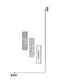
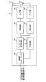
図1は、基地局が少なくとも所定シンボルで送信期間が重複する複数のA-CSIをトリガする場合を示している。ここでは、異なる下り制御情報(例えば、DCI)でそれぞれA-CSI#1とA-CSI#2がトリガされる場合を示している。また、A-CSI#1とA-CSI#2は、少なくとも一部のシンボルで送信期間が重複するPUSCH#1とPUSCH#2を利用して送信することが基地局からUEに指示される。
FIG. 1 shows a case where the base station triggers a plurality of A-CSIs whose transmission periods overlap at least with a predetermined symbol. Here, a case where A-CSI # 1 and A-CSI # 2 are triggered by different downlink control information (for example, DCI) is shown. Further, the base station instructs the UE to transmit A-CSI # 1 and A-CSI # 2 by using PUSCH # 1 and PUSCH # 2 whose transmission periods overlap at least in some symbols.
このように少なくとも一部のシンボルで送信期間が重複する複数のA-CSI(又は、PUSCH)等がトリガされることが許容される場合(図1参照)、UEはトリガされたA-CSI等の送信をどのように制御するかが問題となる。
When it is allowed to trigger a plurality of A-CSI (or PUSCH) or the like whose transmission periods overlap in at least some symbols in this way (see FIG. 1), the UE is triggered A-CSI or the like. The problem is how to control the transmission of.
そこで、本発明者らは、シンボル単位で送信期間が重複するA-CSI等のUL送信のトリガ有無とUL送信の送信制御について検討し、当該UL送信を適切に行うための方法を着想した。
Therefore, the present inventors have studied the presence / absence of a trigger for UL transmission such as A-CSI in which the transmission period overlaps in symbol units and the transmission control of UL transmission, and have come up with a method for appropriately performing the UL transmission.
以下、本開示に係る実施形態について、図面を参照して詳細に説明する。各実施形態に係る無線通信方法は、それぞれ単独で適用されてもよいし、組み合わせて適用されてもよい。
Hereinafter, embodiments according to the present disclosure will be described in detail with reference to the drawings. The wireless communication method according to each embodiment may be applied independently or in combination.
ここで、「重複」は、複数の信号及び/又はチャネルが少なくとも一部の同一時間リソース(例えば、同じシンボル)において送信される(送信をトリガ又はスケジュールされる)ことを表す。なお、「重複」は、「衝突」又は「オーバーラップ」と読み替えられてもよい。
Here, “overlap” indicates that multiple signals and / or channels are transmitted (triggered or scheduled for transmission) in at least some of the same time resources (eg, the same symbol). Note that “overlap” may be read as “collision” or “overlap”.
時間リソースの単位は、シンボルに限られず、スロット、ミニスロット、サブフレームなどで読み替えられてもよい。
The unit of time resource is not limited to symbols, but may be read as slots, minislots, subframes, and the like.
また、以下の実施の態様は、CAを行う場合だけでなくCAを行わない場合にも適用することができる。また、以下の説明では、UL送信としてA-CSIを主に例に挙げて説明するが、他のUL送信に適用してもよい。他のUL送信は、下り制御情報(例えば、DCI)でスケジューリングされるULデータ(又は、PUSCH)送信、DCIでスケジューリングされないULデータ(又は、PUSCH)送信、サウンディングリファレンス信号(例えば、SRS)送信であってもよい。
Also, the following embodiments can be applied not only when CA is performed but also when CA is not performed. In the following description, A-CSI is mainly described as an example of UL transmission, but may be applied to other UL transmissions. Other UL transmissions include UL data (or PUSCH) transmission scheduled with downlink control information (for example, DCI), UL data (or PUSCH) transmission not scheduled with DCI, and sounding reference signal (for example, SRS) transmission. There may be.
また、以下の実施の態様は、P-CSI又はSP-CSIに対しても適用してもよい。SP-CSIは、半永続的(半持続的、セミパーシステント(Semi-Persistent))に指定されるリソースを用いたCSI報告を指す。
Also, the following embodiments may be applied to P-CSI or SP-CSI. SP-CSI refers to CSI reporting using resources specified as semi-persistent (semi-persistent, semi-persistent).
(第1の態様)
第1の態様は、少なくとも所定セルにおいて、所定シンボルを利用したUL送信(例えば、A-CSI報告)を1つに制限する。つまり、所定シンボルにおいて送信期間が重複する複数のUL送信(例えば、A-CSI)を制限し、UL送信がシンボルレベルで重複しないようにトリガを制御する。
(First aspect)
The first aspect limits UL transmission (for example, A-CSI report) using a predetermined symbol to one in at least a predetermined cell. That is, a plurality of UL transmissions (for example, A-CSI) whose transmission periods overlap in a predetermined symbol are limited, and the trigger is controlled so that UL transmissions do not overlap at the symbol level.
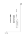
UEは、所定サービングセルにおいて、異なるDCIでトリガされるA-CSI報告が同じシンボルで重複しないと想定してもよい。例えば、A-CSI報告がPUSCHを利用して行われる場合、UEは、各DCIでトリガされたA-CSIがそれぞれ割当てられるPUSCHリソースが重複しないシンボルにスケジュールされると想定する(図2参照)。
The UE may assume that A-CSI reports triggered by different DCIs do not overlap with the same symbol in a given serving cell. For example, when the A-CSI report is performed using PUSCH, the UE assumes that PUSCH resources to which A-CSI triggered by each DCI is respectively allocated are scheduled to symbols that do not overlap (see FIG. 2). .
図2は、A-CSI#1の送信に利用するPUSCH#1と、A-CSI#2の送信に利用するPUSCH#2がそれぞれ異なるシンボル(例えば、重複しないシンボル)にスケジューリングされる場合の一例を示している。A-CSI#1のトリガを指示するDCIには、PUSCH#1のスケジューリング情報(例えば、PUSCH#1のリソース情報)が含まれていてもよい。同様に、A-CSI#2のトリガを指示するDCIには、PUSCH#2のスケジューリング情報(例えば、PUSCH#2のリソース情報)が含まれていてもよい。
FIG. 2 shows an example in which PUSCH # 1 used for transmission of A-CSI # 1 and PUSCH # 2 used for transmission of A-CSI # 2 are scheduled to different symbols (for example, non-overlapping symbols). Is shown. The DCI instructing the trigger of A-CSI # 1 may include PUSCH # 1 scheduling information (for example, PUSCH # 1 resource information). Similarly, the scheduling information of PUSCH # 2 (for example, resource information of PUSCH # 2) may be included in DCI instructing the trigger of A-CSI # 2.
このように、所定シンボルを利用したUL送信(例えば、A-CSI報告)を1つに制限することにより、複数のUL送信が重複するケースを考慮する必要がないため、A-CSI等の送信処理を簡略化することができる。
In this way, by limiting the UL transmission (for example, A-CSI report) using a predetermined symbol to one, it is not necessary to consider the case where a plurality of UL transmissions overlap. Processing can be simplified.
なお、ULにおいてCAが適用される場合、異なるサービングセル(又は、CC)間では、異なるDCIでトリガされる複数のA-CSI(又は、各A-CSIを多重する複数のPUSCH)が少なくとも一部のシンボルで重複する構成としてもよい。
When CA is applied in the UL, at least a part of a plurality of A-CSIs (or a plurality of PUSCHs that multiplex each A-CSI) triggered by different DCIs are provided between different serving cells (or CCs). It is good also as a structure which overlaps with the symbol of.
あるいは、UEは、所定のPUCCHグループ及びセルグループの少なくとも一つにおいて、異なるDCIでトリガされるA-CSI報告の送信期間が同じシンボルで重複しないと想定してもよい。この場合、UEは、ULにおいてCAが適用される場合、同じPUCCHグループ(又はセルグループ)に含まれる複数のCC間において、複数のA-CSI(又は、各A-CSIを多重する複数のPUSCH)が同じシンボルで重複されないと想定する。
Alternatively, the UE may assume that the transmission periods of A-CSI reports triggered by different DCIs do not overlap with the same symbol in at least one of the predetermined PUCCH group and cell group. In this case, when CA is applied in the UL, the UE may use multiple A-CSIs (or multiple PUSCHs that multiplex each A-CSI) between multiple CCs included in the same PUCCH group (or cell group). ) Are not duplicated in the same symbol.
PUCCHグループは、PUCCHの送信を行うセル(PCell又はPUCCH SCell)に対応づけられるセカンダリセルを含む複数のセルで構成されるグループである。また、セルグループは、デュアルコネクティビティ(DC)を適用する場合のPCellを含むマスタセルグループ(MCG)と、PSCellを含むセカンダリセルグループ(SCG)を含むグループである。
The PUCCH group is a group including a plurality of cells including secondary cells associated with a cell (PCell or PUCCH SCell) that transmits PUCCH. The cell group is a group including a master cell group (MCG) including a PCell and a secondary cell group (SCG) including a PSCell when applying dual connectivity (DC).
このように、PUCCHグループ又はセルグループにおいて、複数のA-CSI報告の送信期間が同じシンボルで重複しないように制御することにより、PUCCHグループまたはセルグループが異なるセル間ではA-CSI報告の送信期間を同じシンボルで重複させることができる。その結果、複数のPUCCHグループ及び/又はセルグループが設定された場合に、より柔軟にA-CSI報告を制御することができる。
Thus, in the PUCCH group or the cell group, by controlling so that the transmission periods of a plurality of A-CSI reports do not overlap with the same symbol, the transmission period of the A-CSI report is different between cells with different PUCCH groups or cell groups. Can be duplicated with the same symbol. As a result, when a plurality of PUCCH groups and / or cell groups are set, A-CSI reporting can be controlled more flexibly.
<変形例>
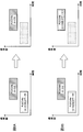
異なるDCIでトリガされる複数のA-CSI報告は、同一のスロット内で行われる構成としてもよい。つまり、当該複数のA-CSI報告の送信期間(又は、各A-CSI報告に利用するPUSCHの送信期間)が所定スロットにおいて同じシンボルで重複しないように制御してもよい(図3A参照)。
<Modification>
A plurality of A-CSI reports triggered by different DCIs may be configured to be performed in the same slot. That is, the transmission period of the plurality of A-CSI reports (or the transmission period of PUSCH used for each A-CSI report) may be controlled so as not to overlap with the same symbol in a predetermined slot (see FIG. 3A).
図3Aでは、DCI#1でトリガされるA-CSI(又は、スケジューリングされるPUSCH#1)と、DCI#2でトリガされるA-CSI#2(又はスケジューリングされるPUSCH#2)が同一スロット内容の異なるシンボルで送信される。このように、スロット内の異なるシンボルを利用した複数のA-CSI等のUL送信のトリガを許容することにより、A-CSI報告等の遅延を抑制することができる。
In FIG. 3A, A-CSI triggered by DCI # 1 (or scheduled PUSCH # 1) and A-CSI # 2 triggered by DCI # 2 (or scheduled PUSCH # 2) are in the same slot. Sent with different symbols. As described above, by allowing a plurality of UL transmission triggers such as A-CSI using different symbols in the slot, it is possible to suppress delays such as A-CSI reporting.
あるいは、異なるDCIでトリガされる複数のA-CSI報告は、同一のスロット内で行わない構成としてもよい。つまり、当該複数のA-CSI報告の送信期間(又は、各A-CSI報告に利用するPUSCHの送信期間)が同じスロットで重複しないように制御してもよい(図3B参照)。図3Bでは、所定スロットにおいて、DCI#1でトリガされるA-CSI(又は、スケジューリングされるPUSCH#1)のみが送信される場合を示している。このようにすることで、複数のUL送信がスロット内で重複するケースを考慮する必要がないため、A-CSI等の送信処理をさらに簡略化することができる。
Alternatively, a plurality of A-CSI reports triggered by different DCIs may not be performed in the same slot. That is, the transmission period of the plurality of A-CSI reports (or the transmission period of PUSCH used for each A-CSI report) may be controlled so as not to overlap in the same slot (see FIG. 3B). FIG. 3B shows a case where only A-CSI triggered by DCI # 1 (or scheduled PUSCH # 1) is transmitted in a predetermined slot. By doing so, it is not necessary to consider the case where a plurality of UL transmissions overlap in a slot, so that transmission processing such as A-CSI can be further simplified.
また、上述したUL送信制御において、所定シンボルを利用したUL送信(例えば、A-CSI報告)を、スロットあたり最大1つに制限する必要があるか、スロットあたりは2つ以上と出来るものの所定シンボルあたり最大1つに制限するかを、ユーザ端末が、端末能力情報(UE capability signalling)として無線基地局に報告するものとしてもよい。これにより、無線基地局は、報告された端末能力情報をもとに、所定シンボルを利用したUL送信(例えば、A-CSI報告)を適切に制御することができる。
Further, in the above-described UL transmission control, it is necessary to limit UL transmission (for example, A-CSI report) using a predetermined symbol to a maximum of one per slot, or a predetermined symbol that can be two or more per slot The user terminal may report to the radio base station as terminal capability information (UE capability signaling) whether or not the maximum number is limited per one. Accordingly, the radio base station can appropriately control UL transmission (for example, A-CSI report) using a predetermined symbol based on the reported terminal capability information.
(第2の態様)
第2の態様は、所定シンボルを利用したUL送信(例えば、A-CSI報告)を複数トリガすることを許容する一方で、当該所定シンボルを利用した実際のUL送信(例えば、A-CSI報告又はPUSCH送信)を一つに制限する。つまり、無線基地局は、所定シンボルにおいて送信期間が重複する複数のUL送信(例えば、A-CSI)のトリガを行えるものとし、ユーザ端末は、重複するUL送信のうち一部を送信する(残りをドロップ又はキャンセルする)ように制御する。
(Second aspect)
The second aspect allows multiple UL transmissions (eg, A-CSI reports) using a predetermined symbol to be triggered, while actual UL transmissions (eg, A-CSI report or (PUSCH transmission) is limited to one. That is, the radio base station can trigger a plurality of UL transmissions (for example, A-CSI) whose transmission periods overlap in a predetermined symbol, and the user terminal transmits a part of the overlapping UL transmissions (the remaining To drop or cancel).
図4は、所定シンボルにおいてN個(N>1、ここではN=3)のPUSCH#1-#3が重複してスケジューリングされる場合を示している。例えば、基地局は、PUSCH#1-#3を利用したN個のA-CSI(例えば、A-CSI#1-#3)報告をトリガする。UEは、N個のA-CSI報告のうち一部(例えば、1つのA-CSI)を選択して報告するように制御する。
FIG. 4 shows a case where N (N> 1, N = 3 in this case) PUSCH # 1- # 3 are scheduled redundantly in a predetermined symbol. For example, the base station triggers N A-CSI (eg, A-CSI # 1- # 3) reports using PUSCH # 1- # 3. The UE controls to select and report a part of the N A-CSI reports (for example, one A-CSI).
つまり、UEは、同じシンボルを利用して送信される複数のUL送信(例えば、A-CSI報告(又は、A-CSIを多重するPUSCH送信))がトリガされた場合、所定条件に基づいて一部のUL送信を選択し、残りのUL送信をドロップする。
That is, when a plurality of UL transmissions (for example, A-CSI report (or PUSCH transmission in which A-CSI is multiplexed)) transmitted using the same symbol are triggered, the UE performs a transmission based on a predetermined condition. Select the part UL transmission and drop the remaining UL transmission.
以下に、UL送信(例えば、A-CSI又はPUSCH)の所定のドロップ条件又は送信条件に基づいてUL送信を制御する場合について例を挙げて説明する。なお、以下の説明では、第1のPUSCH送信と、当該第1のPUSCH送信より送信開始タイミングが遅い第2のPUSCH送信を例に挙げて説明するが、適用可能なPUSCH送信は2つに限られない。また、第1のPUSCH送信及び第2のPUSCH送信は、PUSCH送信以外の他のUL送信に置き換えてもよい。
Hereinafter, an example will be described in which UL transmission is controlled based on a predetermined drop condition or transmission condition of UL transmission (for example, A-CSI or PUSCH). In the following description, the first PUSCH transmission and the second PUSCH transmission whose transmission start timing is later than that of the first PUSCH transmission will be described as an example. However, the applicable PUSCH transmission is limited to two. I can't. Further, the first PUSCH transmission and the second PUSCH transmission may be replaced with other UL transmissions other than the PUSCH transmission.
<UL送信方法1>
UL送信方法1では、送信開始タイミングに基づいて送信又はドロップすべきUL送信(例えば、送信に利用するPUSCHリソース、A-CSI送信、ULデータ等)を判断する。
<UL transmission method 1>
In the UL transmission method 1, UL transmission to be transmitted or dropped (for example, PUSCH resource used for transmission, A-CSI transmission, UL data, etc.) is determined based on the transmission start timing.
例えば、送信開始タイミングが遅い第2のPUSCH送信(又は、第2のPUSCHリソースを利用した送信)を第1のPUSCH送信(又は、第1のPUSCHリソースを利用した送信)より優先して送信を行うように制御してもよい。つまり、UEは、第1のPUSCH送信(又は、第1のA-CSI報告)と第2のPUSCH送信(又は、第2のA-CSI報告)がトリガされた場合、送信開始タイミングが早い第1のPUSCH送信(on-going PUSCH送信)をキャンセルし、第2のPUSCH送信を行う(図5参照)。
For example, the second PUSCH transmission (or transmission using the second PUSCH resource) whose transmission start timing is late is given priority over the first PUSCH transmission (or transmission using the first PUSCH resource). You may control to do. That is, when the first PUSCH transmission (or the first A-CSI report) and the second PUSCH transmission (or the second A-CSI report) are triggered, the UE has a transmission start timing earlier. Cancel the first PUSCH transmission (on-going PUSCH transmission) and perform the second PUSCH transmission (see FIG. 5).
なお、ここで所定のPUSCH送信をドロップまたはキャンセルする、とは、キャンセル動作を開始してから当該PUSCH送信に与える送信電力を所定時間(例えば20us)内に所定レベル(例えば-40dBm)以下とする、などと定義してもよい。この場合、ユーザ端末がドロップまたはキャンセルした所定のPUSCH送信を継続することを回避し、干渉を減らすことができる。または当該PUSCH送信の送信品質(例えばEVM)を所定レベル以下にすることを許容する、などと定義してもよい。この場合、実際に送信を止めるか否か(またはどのように止めるか)はユーザ端末次第となるため、多様な実装によりキャンセル動作を実現できるようになる。
Here, dropping or canceling a predetermined PUSCH transmission means that the transmission power given to the PUSCH transmission after starting the cancel operation is set to a predetermined level (for example, −40 dBm) or less within a predetermined time (for example, 20 us). , Etc. may be defined. In this case, it is possible to avoid continuing the predetermined PUSCH transmission dropped or canceled by the user terminal, and reduce interference. Alternatively, it may be defined that the transmission quality (for example, EVM) of the PUSCH transmission is allowed to be a predetermined level or less. In this case, whether to actually stop transmission (or how to stop) depends on the user terminal, so that the cancel operation can be realized by various implementations.
図5では、少なくとも一部のシンボルで送信期間が重複する第1のPUSCHリソースを利用した送信(PUSCH#a)と、第2のPUSCHリソースを利用した送信(PUSCH#b)がトリガ又はスケジューリングされた場合、PUSCH#bを優先して送信する場合を示している。このように、送信開始タイミングが遅い第2のPUSCHリソースを利用した送信を優先することにより、基地局から指示された最新の指示に基づいてUL送信を制御することができる。
In FIG. 5, transmission using the first PUSCH resource (PUSCH # a) and transmission using the second PUSCH resource (PUSCH # b) in which transmission periods overlap in at least some symbols are triggered or scheduled. In this case, PUSCH #b is preferentially transmitted. Thus, by giving priority to the transmission using the second PUSCH resource whose transmission start timing is late, it is possible to control the UL transmission based on the latest instruction instructed from the base station.
図5において、UEは、第1のPUSCHリソース(PUSCH#a)を利用して送信するUL信号(例えば、A-CSI及びULデータの少なくとも一つ)をドロップ又はキャンセルする。例えば、PUSCH#aを用いてA-CSI報告ID#1及び#3を含むA-CSI#aを送信し、PUSCH#bを用いてA-CSI報告ID#2及び#4を含むA-CSI#bを送信することが基地局からUEに指示される場合を想定する。この場合、UEは、PUSCH#aをキャンセルし、PUSCH#bを利用してA-CSI報告ID#2及び#4を含むA-CSI#bを送信するように制御する。
In FIG. 5, the UE drops or cancels the UL signal (for example, at least one of A-CSI and UL data) to be transmitted using the first PUSCH resource (PUSCH #a). For example, A-CSI #a including A-CSI report IDs # 1 and # 3 is transmitted using PUSCH #a, and A-CSI including A-CSI report IDs # 2 and # 4 is transmitted using PUSCH #b. Assume that the base station instructs the UE to transmit #b. In this case, the UE controls to cancel PUSCH # a and transmit A-CSI # b including A-CSI report ID # 2 and # 4 using PUSCH # b.
このように、基地局からトリガ又はスケジューリングされるUL送信(例えば、PUSCH送信)の送信開始タイミングに基づいて、送信するPUSCH及びドロップするPUSCHの少なくとも一方を決定する。これにより、少なくとも一部のシンボルで送信期間が重複するPUSCH送信(例えば、A-CSI報告)がトリガされた場合でも、送信すべきPUSCH送信を適切に判断して送信できる。
Thus, based on the transmission start timing of UL transmission (for example, PUSCH transmission) triggered or scheduled by the base station, at least one of PUSCH to be transmitted and PUSCH to be dropped is determined. Thereby, even when PUSCH transmission (for example, A-CSI report) in which transmission periods overlap in at least some symbols is triggered, it is possible to appropriately determine and transmit PUSCH transmission to be transmitted.
<UL送信方法2>
UL送信方法2では、送信開始タイミング及び所定の優先条件の少なくとも一つに基づいて送信又はドロップすべきUL送信(例えば、送信に利用するPUSCHリソース、A-CSI送信、ULデータ等)を判断する。
<UL transmission method 2>
In UL transmission method 2, UL transmission to be transmitted or dropped (for example, PUSCH resource used for transmission, A-CSI transmission, UL data, etc.) is determined based on at least one of transmission start timing and a predetermined priority condition. .
例えば、送信開始タイミングが遅い第2のPUSCH送信(又は、第2のPUSCHリソースを利用した送信)を第1のPUSCH送信(又は、第1のPUSCHリソースを利用した送信)より優先して送信するように制御してもよい。また、第2のPUSCHリソースを利用して送信するUL信号は、所定の優先条件に基づいて決定する。
For example, the second PUSCH transmission (or transmission using the second PUSCH resource) whose transmission start timing is late is transmitted with priority over the first PUSCH transmission (or transmission using the first PUSCH resource). You may control as follows. In addition, the UL signal to be transmitted using the second PUSCH resource is determined based on a predetermined priority condition.
優先条件は、UL送信の方式(例えば、UL送信がURLLC(Ultra Reliable and Low Latency Communications)であるかeMBB(enhanced Mobile Broad Band)であるか等)、UL信号種別、対応するセル種別、各信号のインデックス番号の少なくとも一つに基づいて決定してもよい。なお、優先条件は、あらかじめ仕様で定義してもよいし、基地局からUEに上位レイヤシグナリング及び下り制御情報の少なくとも一つを利用して通知してもよい。
Priority conditions are UL transmission methods (for example, whether UL transmission is URLLC (Ultra Reliable and Low Latency Communications) or eMBB (enhanced Mobile BroadBBand)), UL signal type, corresponding cell type, each signal It may be determined based on at least one of the index numbers. The priority condition may be defined in advance in the specification, or may be notified from the base station to the UE using at least one of higher layer signaling and downlink control information.
例えば、以下の優先条件#aと優先条件#bに基づいて、送信するUL信号(又は、ドロップするUL信号)を決定してもよい。この場合、優先条件#aに基づいて判断した後に、優先条件#bを考慮すればよい。ここでは、優先条件#aがUL送信の方式に関する優先度を示し、優先条件#bがUL信号種別に関する優先度を示している。なお、優先条件#bとして、信号種別が同じUL信号に対する優先条件をさらに規定してもよい。なお、優先条件#a、#bは、一例でありこれに限られない。各優先条件における優先順序は適宜入れ替えてもよい。また、UL送信の方式はULRRCとeMBBに限られない。
For example, the UL signal to be transmitted (or the UL signal to be dropped) may be determined based on the following priority condition #a and priority condition #b. In this case, after determining based on the priority condition #a, the priority condition #b may be considered. Here, priority condition #a indicates the priority regarding the UL transmission method, and priority condition #b indicates the priority regarding the UL signal type. Note that priority conditions for UL signals having the same signal type may be further defined as priority conditions #b. The priority conditions #a and #b are examples and are not limited thereto. The priority order in each priority condition may be changed as appropriate. The UL transmission method is not limited to ULRRC and eMBB.
・優先条件#a:URLLCに対応するUL信号をeMBBに対応するUL信号より優先する(URLLC>eMBB)
・優先条件#b:A-CSI>A-SRS>ULデータ
Priority condition #a: The UL signal corresponding to URLLC is prioritized over the UL signal corresponding to eMBB (URLLC> eMBB)
Priority condition #b: A-CSI>A-SRS> UL data
[優先制御例1]
一例として、図5のPUSCH#a又はPUSCH#bの一方でURLLC用のA-CSIがトリガされ、他方でeMBB用のA-CSIがトリガされた場合を想定する。この場合、UEは、優先条件#aに基づいて、PUSCH#b(第2のPUSCHリソース)を利用してURLLC用のA-CSI報告を行い、eMBB用のA-CSIをドロップするように制御してもよい。
[Priority control example 1]
As an example, it is assumed that A-CSI for URLLC is triggered on one of PUSCH # a or PUSCH # b in FIG. 5 and A-CSI for eMBB is triggered on the other. In this case, the UE performs an A-CSI report for URLLC using PUSCH #b (second PUSCH resource) based on the priority condition #a, and controls to drop the A-CSI for eMBB. May be.
[優先制御例2]
他の例として、図5のPUSCH#a又はPUSCH#bの一方でURLLC用のA-CSIがトリガされ、他方でURLLC用のA-CSIがトリガされた場合を想定する。この場合、UEは、優先条件#aが同じであるため、優先条件#bに基づいて送信するUL信号(又は、ドロップするUL信号)を決定する。なお、ここでは、UL信号種別はA-CSIで同じであるため、信号種別が同じUL信号に対する優先条件を適用してもよい。
[Priority control example 2]
As another example, it is assumed that A-CSI for URLLC is triggered on one of PUSCH # a or PUSCH # b in FIG. 5 and A-CSI for URLLC is triggered on the other. In this case, since the priority condition #a is the same, the UE determines a UL signal to be transmitted (or a UL signal to be dropped) based on the priority condition #b. Here, since the UL signal type is the same in A-CSI, priority conditions for UL signals having the same signal type may be applied.
信号種別が同じUL信号に対する優先条件は、A-CSIの時間領域の動作方法、A-CSIの内容、A-CSIが対応するセルiD、及びCSI報告IDの少なくとも一つに基づいて決定してもよい。例えば、以下の優先条件#b1-#b4に基づいて、送信するCSIを決定してもよい。この場合、優先条件#b-1~#b-4の順に優先的に適用する。
The priority conditions for UL signals with the same signal type are determined based on at least one of the time domain operation method of A-CSI, the contents of A-CSI, the cell iD to which A-CSI corresponds, and the CSI report ID. Also good. For example, the CSI to be transmitted may be determined based on the following priority conditions # b1- # b4. In this case, priority conditions # b-1 to # b-4 are preferentially applied.
・優先条件#b-1:時間領域の動作(A-CSI>PUSCHを利用したSP-CSI>PUCCHを利用したSP-CSI>P-CSI)
・優先条件#b-2:CSI内容(ビーム報告>CSI)
・優先条件#b-3:セルID(PCell>PSCell>SCell(インデックスがより小さいSCell))
・優先条件#b-4:CSI報告ID(インデックスがより小さいCSI報告ID)
Priority condition # b-1: Time domain operation (A-CSI> SP-CSI using PUSCH>SP-CSI>PUCCH> P-CSI)
Priority condition # b-2: CSI content (beam report> CSI)
Priority condition # b-3: Cell ID (PCell>PSCell> SCell (SCell having a smaller index))
Priority condition # b-4: CSI report ID (CSI report ID with a smaller index)
一例として、図5において、PUSCH#aを用いてA-CSI報告ID#1及び#3を含むA-CSI#aを送信し、PUSCH#bを用いてA-CSI報告ID#2及び#4を含むA-CSI#bを送信することが基地局からUEに指示される場合を想定する。A-CSI#aとA-CSI#b間で優先条件#b-1~#b-3まで同じである場合、優先条件#b-4に基づいて、送信するA-CSIを決定する。例えば、UEは、PUSCH#b(第2のPUSCHリソース)を利用して、A-CSI報告ID#1とA-CSI報告ID#2の報告を行う。
As an example, in FIG. 5, A-CSI report IDs # 1 and # 3 including A-CSI report IDs # 1 and # 3 are transmitted using PUSCH #a, and A-CSI report IDs # 2 and # 4 are transmitted using PUSCH #b. Assume that the base station instructs the UE to transmit A-CSI # b including When priority conditions # b-1 to # b-3 are the same between A-CSI #a and A-CSI #b, A-CSI to be transmitted is determined based on priority condition # b-4. For example, the UE reports A-CSI report ID # 1 and A-CSI report ID # 2 using PUSCH # b (second PUSCH resource).
このように、UL送信の方式及びUL信号種別の少なくとも一つに基づいて、送信するUL信号を選択することにより、送信期間が少なくとも一部のシンボルで重複するPUSCH送信がトリガされた場合でも、送信すべきPUSCHリソースとUL信号を適切に判断して送信できる。
Thus, even when PUSCH transmission in which the transmission period overlaps at least some symbols is triggered by selecting the UL signal to be transmitted based on at least one of the UL transmission scheme and the UL signal type, The PUSCH resource to be transmitted and the UL signal can be appropriately determined and transmitted.
[優先制御例3]
他の例として、PUSCH#a又はPUSCH#bの一方でA-CSIのみがトリガされ、他方でA-CSI及びULデータがトリガ又はスケジューリングされた場合を想定する。図6では、PUSCH#aを利用したA-CSI#a及びULデータがトリガ又はスケジューリングされ、PUSCH#bを利用したA-CSI#bがトリガされる場合を示している。
[Priority control example 3]
As another example, assume that only A-CSI is triggered on one of PUSCH # a or PUSCH # b, and A-CSI and UL data are triggered or scheduled on the other. FIG. 6 shows a case where A-CSI # a and UL data using PUSCH # a are triggered or scheduled, and A-CSI # b using PUSCH # b is triggered.
例えば、ULデータよりA-CSIの送信を優先する場合(UL送信の方式が同じであり、優先条件#2を適用する場合)を想定する。この場合、PUSCH#b(第2のPUSCHリソース)を利用してA-CSIを選択的に送信する(ULデータは送信しない)ように制御する(図6A参照)。この場合、PUSCH#bで送信するA-CSIは、あらかじめPUSCH#b用にトリガされたA-CSI#bとしてもよい。あるいは、上述した優先条件#b-1~#b-4に基づいて、送信するA-CSIを決定してもよい。
For example, it is assumed that transmission of A-CSI is prioritized over UL data (when the UL transmission method is the same and priority condition # 2 is applied). In this case, control is performed such that A-CSI is selectively transmitted (UL data is not transmitted) using PUSCH #b (second PUSCH resource) (see FIG. 6A). In this case, the A-CSI transmitted by PUSCH # b may be A-CSI # b triggered in advance for PUSCH # b. Alternatively, the A-CSI to be transmitted may be determined based on the above-described priority conditions # b-1 to # b-4.
あるいは、A-CSI(例えば、A-CSI#b)よりULデータの送信を優先する場合(例えば、ULデータがURLLCを適用し、A-CSI#bがeMBBを適用し、優先条件#1を適用する場合)を想定する。この場合、PUSCH#b(第2のPUSCHリソース)を利用してULデータをA-CSI#bより優先して送信するように制御する(図6B参照)。この場合、PUSCH#bで送信するA-CSIは、ULデータと同様にPUSCH#a用にトリガされたA-CSI#aとしてもよい。あるいは、ULデータのみ送信し、A-CSIを送信しない構成としてもよい。
Alternatively, when transmission of UL data is prioritized over A-CSI (for example, A-CSI #b) (for example, UL data applies URLLC, A-CSI #b applies eMBB, and priority condition # 1 is set. If applicable). In this case, control is performed such that UL data is transmitted with priority over A-CSI # b using PUSCH # b (second PUSCH resource) (see FIG. 6B). In this case, the A-CSI transmitted on the PUSCH #b may be the A-CSI #a triggered for the PUSCH #a as with the UL data. Alternatively, only UL data may be transmitted and A-CSI may not be transmitted.
[優先制御例4]
他の例として、PUSCH#a又はPUSCH#bの一方でULデータのみがスケジューリングされ(A-CSI、A-SRSのトリガなし)、他方でULデータのみがスケジューリングされる(A-CSI、A-SRSのトリガなし)場合を想定する。この場合、UL送信の方式に基づいて実際に送信するULデータを決定する。例えば、一方がURLLC用のULデータであり、他方がeMBB用のULデータである場合、URLLC用のULデータを所定のPUSCHリソース(例えば、第2のPUSCHリソース)を利用して送信する。
[Priority control example 4]
As another example, only UL data is scheduled on one side of PUSCH # a or PUSCH # b (no trigger of A-CSI, A-SRS), and only UL data is scheduled on the other side (A-CSI, A- Assume that there is no SRS trigger). In this case, the UL data to be actually transmitted is determined based on the UL transmission method. For example, if one is URLLC UL data and the other is eMBB UL data, the URLLC UL data is transmitted using a predetermined PUSCH resource (for example, the second PUSCH resource).
[優先制御例5]
他の例として、PUSCH#a又はPUSCH#bの一方でA-SRSがトリガされ、他方でA-CSI及びULデータがトリガ又はスケジューリングされた場合を想定する。
[Priority control example 5]
As another example, assume that A-SRS is triggered on one of PUSCH # a or PUSCH # b and A-CSI and UL data is triggered or scheduled on the other.
UEは、まずA-SRSに適用する送信方式と、A-CSI及びULデータに適用する送信方式(優先条件#a)を考慮する。例えば、A-CSI及びULデータにURLLCを適用し、A-SRSにeMBBを適用する場合、UEは、A-CSI及びULデータを優先して送信し、A-SRSをドロップするように制御する。
UE first considers the transmission method applied to A-SRS and the transmission method (priority condition #a) applied to A-CSI and UL data. For example, when URLLC is applied to A-CSI and UL data and eMBB is applied to A-SRS, the UE controls to transmit A-CSI and UL data with priority and drop A-SRS. .
A-SRSに適用する送信方式と、A-CSI及びULデータに適用する送信方式が同じである場合、UEはUL信号種別の優先度(優先条件#b)に基づいて送信するUL信号を決定する。優先条件#bがA-CSI>A-SRS>ULデータである場合、A-CSIの送信が最も優先されるため、UEは、少なくともA-CSIの送信を行う。
When the transmission method applied to A-SRS and the transmission method applied to A-CSI and UL data are the same, the UE determines the UL signal to be transmitted based on the priority of the UL signal type (priority condition #b). To do. When the priority condition #b is A-CSI> A-SRS> UL data, since the A-CSI transmission has the highest priority, the UE transmits at least A-CSI.
また、A-CSIと同じPUSCHにスケジューリングされたULデータを送信し、A-SRSをドロップするように制御してもよい。あるいは、ULデータをドロップし、A-CSIとA-SRSを送信するように制御してもよい。あるいは、ULデータ及びA-SRSをドロップし、A-CSIのみを送信するように制御してもよい。なお、ULデータ及びA-SRSの少なくとも一つを送信するか否かは、送信に利用するPUSCHリソース(例えば、PUSCH#b)の容量に基づいて決定してもよい。
Also, UL data scheduled on the same PUSCH as A-CSI may be transmitted and A-SRS may be dropped. Alternatively, it may be controlled to drop UL data and transmit A-CSI and A-SRS. Alternatively, it may be controlled to drop UL data and A-SRS and transmit only A-CSI. Whether or not to transmit at least one of UL data and A-SRS may be determined based on the capacity of a PUSCH resource (for example, PUSCH # b) used for transmission.
<変形例>
上記図5、図6では、少なくとも一部のシンボルで送信期間が重複するPUSCH送信(例えば、A-CSI報告)がトリガされた場合に送信開始タイミングが遅い第2のPUSCHリソース(PUSCH#b)を利用する場合を示したが、これに限られない。例えば、図7に示すように、送信開始タイミングが早い第1のPUSCHリソース(PUSCH#a)を利用してもよい。
<Modification>
In FIG. 5 and FIG. 6, the second PUSCH resource (PUSCH # b) whose transmission start timing is late when PUSCH transmission (for example, A-CSI report) whose transmission periods overlap at least in some symbols is triggered. Although the case of using is shown, it is not limited to this. For example, as illustrated in FIG. 7, the first PUSCH resource (PUSCH #a) with early transmission start timing may be used.
例えば、図6A、図6Bで第2のPUSCHリソース(PUSCH#b)を利用するのではなく、図7A、図7Bに示すように第1のPUSCHリソース(PUSCH#a)を利用する構成としてもよい。
For example, instead of using the second PUSCH resource (PUSCH # b) in FIGS. 6A and 6B, the first PUSCH resource (PUSCH # a) may be used as shown in FIGS. 7A and 7B. Good.
あるいは、少なくとも一部のシンボルで送信期間が重複するPUSCH送信(例えば、A-CSI報告)がトリガされた場合、送信開始タイミングでなく他のパラメータ(例えば、送信期間の長さ等)に基づいてUL送信に利用するPUSCHリソースを選択してもよい。
Alternatively, when PUSCH transmission (for example, A-CSI report) whose transmission periods overlap in at least some symbols is triggered, it is not based on the transmission start timing but based on other parameters (for example, the length of the transmission period, etc.) You may select the PUSCH resource utilized for UL transmission.
あるいは、実際に送信するUL信号(例えば、A-CSI及びULデータの少なくとも一つ)に基づいて送信に利用するPUSCHリソースを選択してもよい。例えば、ULデータがスケジューリングされるPUSCHリソース(例えば、図6のPUSCH#a)は、A-CSIのみがトリガされるPUSCHリソース(例えば、図6のPUSCH#b)より割当てられるリソース(例えば、PRB)数が多くなる。
Alternatively, the PUSCH resource used for transmission may be selected based on the UL signal (for example, at least one of A-CSI and UL data) to be actually transmitted. For example, a PUSCH resource (for example, PUSCH # a in FIG. 6) on which UL data is scheduled is a resource (for example, PRB) allocated from a PUSCH resource (for example, PUSCH # b in FIG. 6) in which only A-CSI is triggered. ) Increase the number.
この場合、所定の優先条件に基づいてULデータの送信を行う場合、UEは、当該ULデータがスケジューリングされたPUSCHリソース(図6ではPUSCH#a)を利用してUL送信を行うように制御してもよい。これにより、実際の送信を行うUL送信(例えば、ULデータ)用に割当てられたPUSCHリソースを利用できるため、PUSCHリソースが不足する等の問題を回避することができる。
In this case, when transmitting UL data based on a predetermined priority condition, the UE controls to perform UL transmission using a PUSCH resource (PUSCH #a in FIG. 6) on which the UL data is scheduled. May be. Thereby, since the PUSCH resource allocated for UL transmission (for example, UL data) which performs actual transmission can be used, problems such as a shortage of PUSCH resources can be avoided.
また、上記説明では、異なるDCIでトリガされたA-CSIの送信に利用される複数のPUSCHが所定シンボルで重複する場合、A-CSIの一方を送信する場合を示したがこれに限られない。UEは、所定のPUSCHに割当てるリソース量により決まる符号化率に基づいて当該所定のPUSCHに多重するA-CSIを制御してもよい。
In the above description, when a plurality of PUSCHs used for transmission of A-CSI triggered by different DCIs overlap with each other in a predetermined symbol, one of A-CSI is transmitted. However, the present invention is not limited to this. . The UE may control the A-CSI multiplexed on the predetermined PUSCH based on the coding rate determined by the resource amount allocated to the predetermined PUSCH.
例えば、異なるDCIでトリガされる複数のA-CSIを所定のPUSCHリソースで送信する際に、符号化率が所定値以下となる場合には、当該複数のA-CSIを所定のPUSCHに多重して送信してもよい。これにより、UL送信に利用するPUSCHリソース等に基づいてより多くのA-CSI等を送信できるため、リソースの利用効率を向上することができる。
For example, when transmitting a plurality of A-CSIs triggered by different DCIs using a predetermined PUSCH resource, if the coding rate is equal to or lower than a predetermined value, the plurality of A-CSIs are multiplexed on the predetermined PUSCH. May be transmitted. As a result, more A-CSI and the like can be transmitted based on PUSCH resources and the like used for UL transmission, so that resource utilization efficiency can be improved.
(第3の態様)
第3の態様は、異なるDCIでトリガされたA-CSI等の送信に利用される複数のPUSCHが所定シンボルで重複する場合、当該複数のPUSCHが重複しないように送信開始タイミングをシフトするように制御する。
(Third aspect)
In the third aspect, when a plurality of PUSCHs used for transmission such as A-CSI triggered by different DCIs overlap in a predetermined symbol, the transmission start timing is shifted so that the plurality of PUSCHs do not overlap. Control.
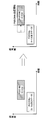
図8は、少なくとも一部のシンボルで重複する第1のPUSCHリソースを利用した送信(PUSCH#a)と、第2のPUSCHリソースを利用した送信(PUSCH#b)がトリガ又はスケジューリングされた場合、PUSCH#aとPUSCH#bが重複しないようにシフトする場合を示している。
FIG. 8 shows a case where transmission using the first PUSCH resource (PUSCH # a) and transmission using the second PUSCH resource (PUSCH # b) that overlap in at least some symbols are triggered or scheduled. The case where it shifts so that PUSCH # a and PUSCH # b do not overlap is shown.
ここでは、送信開始タイミングが遅いPUSCH#bの送信開始タイミングをシフトして、PUSCH#aと重複しないように制御する場合を示している。図8では、PUSCH#aに続けてPUSCH#bが連続して送信されるようにシフトする場合(PUSCH#aの末尾シンボルの次シンボルがPUSCH#bの開始シンボルとなる場合)を示している。これにより、PUSCH#bの遅延の影響を最小限に抑えることができる。
Here, a case is shown in which the transmission start timing of PUSCH #b with a later transmission start timing is shifted and controlled so as not to overlap with PUSCH #a. FIG. 8 shows a case where shifting is performed so that PUSCH # b is transmitted continuously following PUSCH # a (when the next symbol after the last symbol of PUSCH # a becomes the start symbol of PUSCH # b). . Thereby, the influence of the delay of PUSCH # b can be minimized.
なお、PUSCH#aとPUSCH#bが連続しないように当該PUSCH#bをシフトしてもよい。例えば、当該PUSCH#bを、以降の所定スロットで送信するようシフトしてもよい。所定スロットは、上位レイヤシグナリングで定められるUL-DL割り当てやスロットフォーマット通知(SFI)、によって指定されるUL-DL割り当てで、ULと指定・設定された時間区間を有するスロットであってもよい。また、当該所定スロットに対してシフトした場合、当該スロットにおけるPUSCH#bの送信開始シンボルは、当初DCIによって指定されたスタートシンボルと同一であってもよい。これにより、PUSCH#bの送信タイミングを柔軟に制御することができる。
In addition, you may shift the said PUSCH # b so that PUSCH # a and PUSCH # b do not continue. For example, the PUSCH #b may be shifted so as to be transmitted in subsequent predetermined slots. The predetermined slot may be a slot having a time interval designated and set as UL in UL-DL assignment specified by UL-DL assignment or slot format notification (SFI) determined by higher layer signaling. Further, when the shift is performed with respect to the predetermined slot, the transmission start symbol of PUSCH #b in the slot may be the same as the start symbol initially specified by DCI. Thereby, the transmission timing of PUSCH # b can be flexibly controlled.
なお、PUSCH#bをシフトせずに、PUSCH#aと重複するPUSCH#bのシンボルを利用せずにPUSCH#bの送信を行うように制御してもよい。
In addition, you may control to transmit PUSCH # b, without using PUSCH # b symbol which overlaps with PUSCH # a, without shifting PUSCH # b.
(無線通信システム)
以下、本開示の一実施形態に係る無線通信システムの構成について説明する。この無線通信システムでは、本開示の上記各実施形態に係る無線通信方法のいずれか又はこれらの組み合わせを用いて通信が行われる。
(Wireless communication system)
Hereinafter, the configuration of the wireless communication system according to an embodiment of the present disclosure will be described. In this wireless communication system, communication is performed using any one or a combination of the wireless communication methods according to the above-described embodiments of the present disclosure.
図9は、一実施形態に係る無線通信システムの概略構成の一例を示す図である。無線通信システム1では、LTEシステムのシステム帯域幅(例えば、20MHz)を1単位とする複数の基本周波数ブロック(コンポーネントキャリア)を一体としたキャリアアグリゲーション(CA)及び/又はデュアルコネクティビティ(DC)を適用することができる。
FIG. 9 is a diagram illustrating an example of a schematic configuration of a wireless communication system according to an embodiment. In the radio communication system 1, carrier aggregation (CA) and / or dual connectivity (DC) in which a plurality of basic frequency blocks (component carriers) each having a system bandwidth (for example, 20 MHz) of the LTE system as one unit are applied. can do.
なお、無線通信システム1は、LTE(Long Term Evolution)、LTE-A(LTE-Advanced)、LTE-B(LTE-Beyond)、SUPER 3G、IMT-Advanced、4G(4th generation mobile communication system)、5G(5th generation mobile communication system)、NR(New Radio)、FRA(Future Radio Access)、New-RAT(Radio Access Technology)などと呼ばれてもよいし、これらを実現するシステムと呼ばれてもよい。
The wireless communication system 1 includes LTE (Long Term Evolution), LTE-A (LTE-Advanced), LTE-B (LTE-Beyond), SUPER 3G, IMT-Advanced 4G (4th generation mobile communication system), 5G. (5th generation mobile communication system), NR (New Radio), FRA (Future Radio Access), New-RAT (Radio Access Technology), etc., or a system that realizes these.
無線通信システム1は、比較的カバレッジの広いマクロセルC1を形成する無線基地局11と、マクロセルC1内に配置され、マクロセルC1よりも狭いスモールセルC2を形成する無線基地局12(12a-12c)と、を備えている。また、マクロセルC1及び各スモールセルC2には、ユーザ端末20が配置されている。各セル及びユーザ端末20の配置、数などは、図に示す態様に限定されない。
The radio communication system 1 includes a radio base station 11 that forms a macro cell C1 having a relatively wide coverage, and a radio base station 12 (12a-12c) that is arranged in the macro cell C1 and forms a small cell C2 that is narrower than the macro cell C1. It is equipped with. Moreover, the user terminal 20 is arrange | positioned at the macrocell C1 and each small cell C2. The arrangement, the number, and the like of each cell and user terminal 20 are not limited to the mode shown in the figure.
ユーザ端末20は、無線基地局11及び無線基地局12の双方に接続することができる。ユーザ端末20は、マクロセルC1及びスモールセルC2を、CA又はDCを用いて同時に使用することが想定される。また、ユーザ端末20は、複数のセル(CC)を用いてCA又はDCを適用してもよい。
The user terminal 20 can be connected to both the radio base station 11 and the radio base station 12. It is assumed that the user terminal 20 uses the macro cell C1 and the small cell C2 at the same time using CA or DC. Moreover, the user terminal 20 may apply CA or DC using a plurality of cells (CC).
ユーザ端末20と無線基地局11との間は、相対的に低い周波数帯域(例えば、2GHz)で帯域幅が狭いキャリア(既存キャリア、legacy carrierなどとも呼ばれる)を用いて通信を行うことができる。一方、ユーザ端末20と無線基地局12との間は、相対的に高い周波数帯域(例えば、3.5GHz、5GHzなど)で帯域幅が広いキャリアが用いられてもよいし、無線基地局11との間と同じキャリアが用いられてもよい。なお、各無線基地局が利用する周波数帯域の構成はこれに限られない。
Communication between the user terminal 20 and the radio base station 11 can be performed using a carrier having a relatively low frequency band (for example, 2 GHz) and a narrow bandwidth (also referred to as an existing carrier or a legacy carrier). On the other hand, a carrier having a relatively high frequency band (for example, 3.5 GHz, 5 GHz, etc.) and a wide bandwidth may be used between the user terminal 20 and the radio base station 12, or The same carrier may be used. The configuration of the frequency band used by each radio base station is not limited to this.
また、ユーザ端末20は、各セルで、時分割複信(TDD:Time Division Duplex)及び/又は周波数分割複信(FDD:Frequency Division Duplex)を用いて通信を行うことができる。また、各セル(キャリア)では、単一のニューメロロジーが適用されてもよいし、複数の異なるニューメロロジーが適用されてもよい。
Further, the user terminal 20 can perform communication using time division duplex (TDD) and / or frequency division duplex (FDD) in each cell. In each cell (carrier), a single neurology may be applied, or a plurality of different neurology may be applied.
ニューメロロジーとは、ある信号及び/又はチャネルの送信及び/又は受信に適用される通信パラメータであってもよく、例えば、サブキャリア間隔、帯域幅、シンボル長、サイクリックプレフィックス長、サブフレーム長、TTI長、TTIあたりのシンボル数、無線フレーム構成、送受信機が周波数領域で行う特定のフィルタリング処理、送受信機が時間領域で行う特定のウィンドウイング処理などの少なくとも1つを示してもよい。例えば、ある物理チャネルについて、構成するOFDMシンボルのサブキャリア間隔が異なる場合及び/又はOFDMシンボル数が異なる場合には、ニューメロロジーが異なると称されてもよい。
Numerology may be a communication parameter applied to transmission and / or reception of a certain signal and / or channel, for example, subcarrier interval, bandwidth, symbol length, cyclic prefix length, subframe length. , TTI length, number of symbols per TTI, radio frame configuration, specific filtering process performed by the transceiver in the frequency domain, specific windowing process performed by the transceiver in the time domain, and the like. For example, for a certain physical channel, when the subcarrier intervals of the constituting OFDM symbols are different and / or when the number of OFDM symbols is different, it may be referred to as having different neumerities.
無線基地局11と無線基地局12との間(又は、2つの無線基地局12間)は、有線(例えば、CPRI(Common Public Radio Interface)に準拠した光ファイバ、X2インターフェースなど)又は無線によって接続されてもよい。
The wireless base station 11 and the wireless base station 12 (or between the two wireless base stations 12) are connected by wire (for example, optical fiber compliant with CPRI (Common Public Radio Interface), X2 interface, etc.) or wirelessly. May be.
無線基地局11及び各無線基地局12は、それぞれ上位局装置30に接続され、上位局装置30を介してコアネットワーク40に接続される。なお、上位局装置30には、例えば、アクセスゲートウェイ装置、無線ネットワークコントローラ(RNC)、モビリティマネジメントエンティティ(MME)などが含まれるが、これに限定されない。また、各無線基地局12は、無線基地局11を介して上位局装置30に接続されてもよい。
The radio base station 11 and each radio base station 12 are connected to the higher station apparatus 30 and connected to the core network 40 via the higher station apparatus 30. The upper station device 30 includes, for example, an access gateway device, a radio network controller (RNC), a mobility management entity (MME), and the like, but is not limited thereto. Each radio base station 12 may be connected to the higher station apparatus 30 via the radio base station 11.
なお、無線基地局11は、相対的に広いカバレッジを有する無線基地局であり、マクロ基地局、集約ノード、eNB(eNodeB)、送受信ポイント、などと呼ばれてもよい。また、無線基地局12は、局所的なカバレッジを有する無線基地局であり、スモール基地局、マイクロ基地局、ピコ基地局、フェムト基地局、HeNB(Home eNodeB)、RRH(Remote Radio Head)、送受信ポイントなどと呼ばれてもよい。以下、無線基地局11及び12を区別しない場合は、無線基地局10と総称する。
The radio base station 11 is a radio base station having a relatively wide coverage, and may be called a macro base station, an aggregation node, an eNB (eNodeB), a transmission / reception point, or the like. The radio base station 12 is a radio base station having local coverage, and includes a small base station, a micro base station, a pico base station, a femto base station, a HeNB (Home eNodeB), an RRH (Remote Radio Head), and transmission / reception. It may be called a point. Hereinafter, when the radio base stations 11 and 12 are not distinguished, they are collectively referred to as a radio base station 10.
各ユーザ端末20は、LTE、LTE-Aなどの各種通信方式に対応した端末であり、移動通信端末(移動局)だけでなく固定通信端末(固定局)を含んでもよい。
Each user terminal 20 is a terminal that supports various communication schemes such as LTE and LTE-A, and may include not only a mobile communication terminal (mobile station) but also a fixed communication terminal (fixed station).
無線通信システム1においては、無線アクセス方式として、下りリンクに直交周波数分割多元接続(OFDMA:Orthogonal Frequency Division Multiple Access)が適用され、上りリンクにシングルキャリア-周波数分割多元接続(SC-FDMA:Single Carrier Frequency Division Multiple Access)及び/又はOFDMAが適用される。
In the radio communication system 1, as a radio access method, orthogonal frequency division multiple access (OFDMA) is applied to the downlink, and single carrier-frequency division multiple access (SC-FDMA) is used for the uplink. Frequency Division Multiple Access) and / or OFDMA is applied.
OFDMAは、周波数帯域を複数の狭い周波数帯域(サブキャリア)に分割し、各サブキャリアにデータをマッピングして通信を行うマルチキャリア伝送方式である。SC-FDMAは、システム帯域幅を端末毎に1つ又は連続したリソースブロックによって構成される帯域に分割し、複数の端末が互いに異なる帯域を用いることで、端末間の干渉を低減するシングルキャリア伝送方式である。なお、上り及び下りの無線アクセス方式は、これらの組み合わせに限らず、他の無線アクセス方式が用いられてもよい。
OFDMA is a multi-carrier transmission scheme that performs communication by dividing a frequency band into a plurality of narrow frequency bands (subcarriers) and mapping data to each subcarrier. SC-FDMA is a single carrier transmission in which the system bandwidth is divided into bands each composed of one or continuous resource blocks for each terminal, and a plurality of terminals use different bands to reduce interference between terminals. It is a method. The uplink and downlink radio access schemes are not limited to these combinations, and other radio access schemes may be used.
無線通信システム1では、下りリンクのチャネルとして、各ユーザ端末20で共有される下り共有チャネル(PDSCH:Physical Downlink Shared Channel)、ブロードキャストチャネル(PBCH:Physical Broadcast Channel)、下りL1/L2制御チャネルなどが用いられる。PDSCHによって、ユーザデータ、上位レイヤ制御情報、SIB(System Information Block)などが伝送される。また、PBCHによって、MIB(Master Information Block)が伝送される。
In the wireless communication system 1, downlink channels include a downlink shared channel (PDSCH) shared by each user terminal 20, a broadcast channel (PBCH: Physical Broadcast Channel), a downlink L1 / L2 control channel, and the like. Used. User data, higher layer control information, SIB (System Information Block), etc. are transmitted by PDSCH. Moreover, MIB (Master Information Block) is transmitted by PBCH.
下りL1/L2制御チャネルは、PDCCH(Physical Downlink Control Channel)、EPDCCH(Enhanced Physical Downlink Control Channel)、PCFICH(Physical Control Format Indicator Channel)、PHICH(Physical Hybrid-ARQ Indicator Channel)などを含む。PDCCHによって、PDSCH及び/又はPUSCHのスケジューリング情報を含む下り制御情報(DCI:Downlink Control Information)などが伝送される。
Downlink L1 / L2 control channels include PDCCH (Physical Downlink Control Channel), EPDCCH (Enhanced Physical Downlink Control Channel), PCFICH (Physical Control Format Indicator Channel), PHICH (Physical Hybrid-ARQ Indicator Channel), and the like. Downlink control information (DCI: Downlink Control Information) including PDSCH and / or PUSCH scheduling information is transmitted by the PDCCH.
なお、DCIによってスケジューリング情報が通知されてもよい。例えば、DLデータ受信をスケジューリングするDCIは、DLアサインメントと呼ばれてもよいし、ULデータ送信をスケジューリングするDCIは、ULグラントと呼ばれてもよい。
Note that scheduling information may be notified by DCI. For example, DCI for scheduling DL data reception may be referred to as DL assignment, and DCI for scheduling UL data transmission may be referred to as UL grant.
PCFICHによって、PDCCHに用いるOFDMシンボル数が伝送される。PHICHによって、PUSCHに対するHARQ(Hybrid Automatic Repeat reQuest)の送達確認情報(例えば、再送制御情報、HARQ-ACK、ACK/NACKなどともいう)が伝送される。EPDCCHは、PDSCH(下り共有データチャネル)と周波数分割多重され、PDCCHと同様にDCIなどの伝送に用いられる。
The number of OFDM symbols used for PDCCH is transmitted by PCFICH. The PHICH transmits HARQ (Hybrid Automatic Repeat reQuest) delivery confirmation information (for example, retransmission control information, HARQ-ACK, ACK / NACK, etc.) to the PUSCH. EPDCCH is frequency-division multiplexed with PDSCH (downlink shared data channel), and is used for transmission of DCI and the like in the same manner as PDCCH.
無線通信システム1では、上りリンクのチャネルとして、各ユーザ端末20で共有される上り共有チャネル(PUSCH:Physical Uplink Shared Channel)、上り制御チャネル(PUCCH:Physical Uplink Control Channel)、ランダムアクセスチャネル(PRACH:Physical Random Access Channel)などが用いられる。PUSCHによって、ユーザデータ、上位レイヤ制御情報などが伝送される。また、PUCCHによって、下りリンクの無線品質情報(CQI:Channel Quality Indicator)、送達確認情報、スケジューリングリクエスト(SR:Scheduling Request)などが伝送される。PRACHによって、セルとの接続確立のためのランダムアクセスプリアンブルが伝送される。
In the wireless communication system 1, as an uplink channel, an uplink shared channel (PUSCH) shared by each user terminal 20, an uplink control channel (PUCCH: Physical Uplink Control Channel), a random access channel (PRACH: Physical Random Access Channel) is used. User data, higher layer control information, etc. are transmitted by PUSCH. Also, downlink radio quality information (CQI: Channel Quality Indicator), delivery confirmation information, scheduling request (SR), etc. are transmitted by PUCCH. A random access preamble for establishing connection with the cell is transmitted by the PRACH.
無線通信システム1では、下り参照信号として、セル固有参照信号(CRS:Cell-specific Reference Signal)、チャネル状態情報参照信号(CSI-RS:Channel State Information-Reference Signal)、復調用参照信号(DMRS:DeModulation Reference Signal)、位置決定参照信号(PRS:Positioning Reference Signal)などが伝送される。また、無線通信システム1では、上り参照信号として、測定用参照信号(SRS:Sounding Reference Signal)、復調用参照信号(DMRS)などが伝送される。なお、DMRSはユーザ端末固有参照信号(UE-specific Reference Signal)と呼ばれてもよい。また、伝送される参照信号は、これらに限られない。
In the wireless communication system 1, as downlink reference signals, a cell-specific reference signal (CRS), a channel state information reference signal (CSI-RS), and a demodulation reference signal (DMRS: DeModulation Reference Signal), Positioning Reference Signal (PRS), etc. are transmitted. In the wireless communication system 1, a measurement reference signal (SRS: Sounding Reference Signal), a demodulation reference signal (DMRS), and the like are transmitted as uplink reference signals. The DMRS may be referred to as a user terminal specific reference signal (UE-specific Reference Signal). Further, the transmitted reference signal is not limited to these.
(無線基地局)
図10は、一実施形態に係る無線基地局の全体構成の一例を示す図である。無線基地局10は、複数の送受信アンテナ101と、アンプ部102と、送受信部103と、ベースバンド信号処理部104と、呼処理部105と、伝送路インターフェース106と、を備えている。なお、送受信アンテナ101、アンプ部102、送受信部103は、それぞれ1つ以上を含むように構成されればよい。
(Radio base station)
FIG. 10 is a diagram illustrating an example of an overall configuration of a radio base station according to an embodiment. The radio base station 10 includes a plurality of transmission / reception antennas 101, an amplifier unit 102, a transmission / reception unit 103, a baseband signal processing unit 104, a call processing unit 105, and a transmission path interface 106. Note that the transmission / reception antenna 101, the amplifier unit 102, and the transmission / reception unit 103 may each be configured to include one or more.
下りリンクによって無線基地局10からユーザ端末20に送信されるユーザデータは、上位局装置30から伝送路インターフェース106を介してベースバンド信号処理部104に入力される。
User data transmitted from the radio base station 10 to the user terminal 20 via the downlink is input from the higher station apparatus 30 to the baseband signal processing unit 104 via the transmission path interface 106.
ベースバンド信号処理部104では、ユーザデータに関して、PDCP(Packet Data Convergence Protocol)レイヤの処理、ユーザデータの分割・結合、RLC(Radio Link Control)再送制御などのRLCレイヤの送信処理、MAC(Medium Access Control)再送制御(例えば、HARQの送信処理)、スケジューリング、伝送フォーマット選択、チャネル符号化、逆高速フーリエ変換(IFFT:Inverse Fast Fourier Transform)処理、プリコーディング処理などの送信処理が行われて送受信部103に転送される。また、下り制御信号に関しても、チャネル符号化、逆高速フーリエ変換などの送信処理が行われて、送受信部103に転送される。
In the baseband signal processing unit 104, with respect to user data, PDCP (Packet Data Convergence Protocol) layer processing, user data division / combination, RLC (Radio Link Control) retransmission control and other RLC layer transmission processing, MAC (Medium Access) Control) Retransmission control (for example, HARQ transmission processing), scheduling, transmission format selection, channel coding, Inverse Fast Fourier Transform (IFFT) processing, precoding processing, and other transmission processing are performed and the transmission / reception unit 103. The downlink control signal is also subjected to transmission processing such as channel coding and inverse fast Fourier transform, and is transferred to the transmission / reception unit 103.
送受信部103は、ベースバンド信号処理部104からアンテナ毎にプリコーディングして出力されたベースバンド信号を無線周波数帯に変換して送信する。送受信部103で周波数変換された無線周波数信号は、アンプ部102によって増幅され、送受信アンテナ101から送信される。送受信部103は、本開示に係る技術分野での共通認識に基づいて説明されるトランスミッター/レシーバー、送受信回路又は送受信装置から構成することができる。なお、送受信部103は、一体の送受信部として構成されてもよいし、送信部及び受信部から構成されてもよい。
The transmission / reception unit 103 converts the baseband signal output by precoding for each antenna from the baseband signal processing unit 104 to a radio frequency band and transmits the converted signal. The radio frequency signal frequency-converted by the transmission / reception unit 103 is amplified by the amplifier unit 102 and transmitted from the transmission / reception antenna 101. The transmission / reception unit 103 can be configured by a transmitter / receiver, a transmission / reception circuit, or a transmission / reception device described based on common recognition in the technical field according to the present disclosure. In addition, the transmission / reception part 103 may be comprised as an integral transmission / reception part, and may be comprised from a transmission part and a receiving part.
一方、上り信号については、送受信アンテナ101で受信された無線周波数信号がアンプ部102で増幅される。送受信部103はアンプ部102で増幅された上り信号を受信する。送受信部103は、受信信号をベースバンド信号に周波数変換して、ベースバンド信号処理部104に出力する。
On the other hand, for the upstream signal, the radio frequency signal received by the transmission / reception antenna 101 is amplified by the amplifier unit 102. The transmission / reception unit 103 receives the uplink signal amplified by the amplifier unit 102. The transmission / reception unit 103 converts the frequency of the received signal into a baseband signal and outputs it to the baseband signal processing unit 104.
ベースバンド信号処理部104では、入力された上り信号に含まれるユーザデータに対して、高速フーリエ変換(FFT:Fast Fourier Transform)処理、逆離散フーリエ変換(IDFT:Inverse Discrete Fourier Transform)処理、誤り訂正復号、MAC再送制御の受信処理、RLCレイヤ及びPDCPレイヤの受信処理がなされ、伝送路インターフェース106を介して上位局装置30に転送される。呼処理部105は、通信チャネルの呼処理(設定、解放など)、無線基地局10の状態管理、無線リソースの管理などを行う。
The baseband signal processing unit 104 performs fast Fourier transform (FFT) processing, inverse discrete Fourier transform (IDFT: Inverse Discrete Fourier Transform) processing, and error correction on user data included in the input upstream signal. Decoding, MAC retransmission control reception processing, RLC layer and PDCP layer reception processing are performed and transferred to the upper station apparatus 30 via the transmission path interface 106. The call processor 105 performs communication channel call processing (setting, release, etc.), status management of the radio base station 10, radio resource management, and the like.
伝送路インターフェース106は、所定のインターフェースを介して、上位局装置30と信号を送受信する。また、伝送路インターフェース106は、基地局間インターフェース(例えば、CPRI(Common Public Radio Interface)に準拠した光ファイバ、X2インターフェース)を介して他の無線基地局10と信号を送受信(バックホールシグナリング)してもよい。
The transmission path interface 106 transmits and receives signals to and from the higher station apparatus 30 via a predetermined interface. The transmission path interface 106 transmits / receives signals (backhaul signaling) to / from other radio base stations 10 via an interface between base stations (for example, an optical fiber compliant with CPRI (Common Public Radio Interface), X2 interface). May be.
送受信部103は、DCIで指定するリソースを用いて、ユーザ端末20から送信されたチャネル状態情報(例えば、A-CSI)を受信してもよい。送受信部103は、ユーザ端末20に対して、CSIの送信指示(トリガ又はULグラント)を送信してもよい。また、送受信部103は、A-CSI報告の優先度に関する情報などを、ユーザ端末20に送信してもよい。
The transmission / reception unit 103 may receive channel state information (for example, A-CSI) transmitted from the user terminal 20 using a resource specified by DCI. The transmission / reception unit 103 may transmit a CSI transmission instruction (trigger or UL grant) to the user terminal 20. Further, the transmission / reception unit 103 may transmit information on the priority of the A-CSI report to the user terminal 20.
図11は、本開示の一実施形態に係る無線基地局の機能構成の一例を示す図である。なお、本例では、本実施形態における特徴部分の機能ブロックを主に示しており、無線基地局10は、無線通信に必要な他の機能ブロックも有すると想定されてもよい。
FIG. 11 is a diagram illustrating an example of a functional configuration of a radio base station according to an embodiment of the present disclosure. In addition, in this example, the functional block of the characteristic part in this embodiment is mainly shown, and it may be assumed that the wireless base station 10 also has other functional blocks necessary for wireless communication.
ベースバンド信号処理部104は、制御部(スケジューラ)301と、送信信号生成部302と、マッピング部303と、受信信号処理部304と、測定部305と、を少なくとも備えている。なお、これらの構成は、無線基地局10に含まれていればよく、一部又は全部の構成がベースバンド信号処理部104に含まれなくてもよい。
The baseband signal processing unit 104 includes at least a control unit (scheduler) 301, a transmission signal generation unit 302, a mapping unit 303, a reception signal processing unit 304, and a measurement unit 305. These configurations may be included in the radio base station 10, and a part or all of the configurations may not be included in the baseband signal processing unit 104.
制御部(スケジューラ)301は、無線基地局10全体の制御を実施する。制御部301は、本開示に係る技術分野での共通認識に基づいて説明されるコントローラ、制御回路又は制御装置から構成することができる。
The control unit (scheduler) 301 controls the entire radio base station 10. The control unit 301 can be configured by a controller, a control circuit, or a control device described based on common recognition in the technical field according to the present disclosure.
制御部301は、例えば、送信信号生成部302における信号の生成、マッピング部303における信号の割り当てなどを制御する。また、制御部301は、受信信号処理部304における信号の受信処理、測定部305における信号の測定などを制御する。
The control unit 301 controls, for example, signal generation in the transmission signal generation unit 302, signal allocation in the mapping unit 303, and the like. The control unit 301 also controls signal reception processing in the reception signal processing unit 304, signal measurement in the measurement unit 305, and the like.
制御部301は、システム情報、下りデータ信号(例えば、PDSCHで送信される信号)、下り制御信号(例えば、PDCCH及び/又はEPDCCHで送信される信号。送達確認情報など)のスケジューリング(例えば、リソース割り当て)を制御する。また、制御部301は、上りデータ信号に対する再送制御の要否を判定した結果などに基づいて、下り制御信号、下りデータ信号などの生成を制御する。
The control unit 301 schedules system information, downlink data signals (for example, signals transmitted by PDSCH), downlink control signals (for example, signals transmitted by PDCCH and / or EPDCCH, delivery confirmation information, etc.) (for example, resource Control). In addition, the control unit 301 controls generation of a downlink control signal, a downlink data signal, and the like based on a result of determining whether or not retransmission control is necessary for the uplink data signal.
制御部301は、同期信号(例えば、PSS(Primary Synchronization Signal)/SSS(Secondary Synchronization Signal))、下り参照信号(例えば、CRS、CSI-RS、DMRS)などのスケジューリングの制御を行う。
The control unit 301 controls scheduling of synchronization signals (for example, PSS (Primary Synchronization Signal) / SSS (Secondary Synchronization Signal)), downlink reference signals (for example, CRS, CSI-RS, DMRS).
制御部301は、上りデータ信号(例えば、PUSCHで送信される信号)、上り制御信号(例えば、PUCCH及び/又はPUSCHで送信される信号。送達確認情報など)、ランダムアクセスプリアンブル(例えば、PRACHで送信される信号)、上り参照信号などのスケジューリングを制御する。
The control unit 301 includes an uplink data signal (for example, a signal transmitted by PUSCH), an uplink control signal (for example, a signal transmitted by PUCCH and / or PUSCH, delivery confirmation information, etc.), a random access preamble (for example, by PRACH). (Sending signal), scheduling of uplink reference signals and the like are controlled.
制御部301は、複数のUL信号(例えば、A-CSI)の送信期間が同じシンボルで重複しないように制御してもよい。また、異なる下り制御情報に基づいて送信を指示する複数のUL信号の送信期間が同一スロット内の異なるシンボルに設定するように制御してもよいし、複数のUL信号の送信期間が同一スロット内には設定されないように制御してもよい。
The control unit 301 may perform control so that transmission periods of a plurality of UL signals (for example, A-CSI) do not overlap with the same symbol. Further, it may be controlled such that the transmission periods of a plurality of UL signals instructing transmission based on different downlink control information are set to different symbols in the same slot, or the transmission periods of the plurality of UL signals are within the same slot. You may control so that it is not set to.
送信信号生成部302は、制御部301からの指示に基づいて、下り信号(下り制御信号、下りデータ信号、下り参照信号など)を生成して、マッピング部303に出力する。送信信号生成部302は、本開示に係る技術分野での共通認識に基づいて説明される信号生成器、信号生成回路又は信号生成装置から構成することができる。
The transmission signal generation unit 302 generates a downlink signal (downlink control signal, downlink data signal, downlink reference signal, etc.) based on an instruction from the control unit 301, and outputs it to the mapping unit 303. The transmission signal generation unit 302 can be configured by a signal generator, a signal generation circuit, or a signal generation device described based on common recognition in the technical field according to the present disclosure.
送信信号生成部302は、例えば、制御部301からの指示に基づいて、下りデータの割り当て情報を通知するDLアサインメント及び/又は上りデータの割り当て情報を通知するULグラントを生成する。DLアサインメント及びULグラントは、いずれもDCIであり、DCIフォーマットに従う。また、下りデータ信号には、各ユーザ端末20からのチャネル状態情報(CSI:Channel State Information)などに基づいて決定された符号化率、変調方式などに従って符号化処理、変調処理が行われる。
The transmission signal generation unit 302 generates, for example, a DL assignment for notifying downlink data allocation information and / or a UL grant for notifying uplink data allocation information based on an instruction from the control unit 301. The DL assignment and UL grant are both DCI and follow the DCI format. In addition, the downlink data signal is subjected to coding processing and modulation processing according to a coding rate, a modulation scheme, and the like determined based on channel state information (CSI: Channel State Information) from each user terminal 20.
マッピング部303は、制御部301からの指示に基づいて、送信信号生成部302で生成された下り信号を、所定の無線リソースにマッピングして、送受信部103に出力する。マッピング部303は、本開示に係る技術分野での共通認識に基づいて説明されるマッパー、マッピング回路又はマッピング装置から構成することができる。
The mapping unit 303 maps the downlink signal generated by the transmission signal generation unit 302 to a predetermined radio resource based on an instruction from the control unit 301, and outputs it to the transmission / reception unit 103. The mapping unit 303 can be configured by a mapper, a mapping circuit, or a mapping device described based on common recognition in the technical field according to the present disclosure.
受信信号処理部304は、送受信部103から入力された受信信号に対して、受信処理(例えば、デマッピング、復調、復号など)を行う。ここで、受信信号は、例えば、ユーザ端末20から送信される上り信号(上り制御信号、上りデータ信号、上り参照信号など)である。受信信号処理部304は、本開示に係る技術分野での共通認識に基づいて説明される信号処理器、信号処理回路又は信号処理装置から構成することができる。
The reception signal processing unit 304 performs reception processing (for example, demapping, demodulation, decoding, etc.) on the reception signal input from the transmission / reception unit 103. Here, the received signal is, for example, an uplink signal (uplink control signal, uplink data signal, uplink reference signal, etc.) transmitted from the user terminal 20. The reception signal processing unit 304 can be configured by a signal processor, a signal processing circuit, or a signal processing device described based on common recognition in the technical field according to the present disclosure.
受信信号処理部304は、受信処理によって復号された情報を制御部301に出力する。例えば、HARQ-ACKを含むPUCCHを受信した場合、HARQ-ACKを制御部301に出力する。また、受信信号処理部304は、受信信号及び/又は受信処理後の信号を、測定部305に出力する。
The reception signal processing unit 304 outputs the information decoded by the reception processing to the control unit 301. For example, when receiving PUCCH including HARQ-ACK, HARQ-ACK is output to control section 301. The reception signal processing unit 304 outputs the reception signal and / or the signal after reception processing to the measurement unit 305.
測定部305は、受信した信号に関する測定を実施する。測定部305は、本開示に係る技術分野での共通認識に基づいて説明される測定器、測定回路又は測定装置から構成することができる。
The measurement unit 305 performs measurement on the received signal. The measurement unit 305 can be configured from a measurement device, a measurement circuit, or a measurement device described based on common recognition in the technical field according to the present disclosure.
例えば、測定部305は、受信した信号に基づいて、RRM(Radio Resource Management)測定、CSI(Channel State Information)測定などを行ってもよい。測定部305は、受信電力(例えば、RSRP(Reference Signal Received Power))、受信品質(例えば、RSRQ(Reference Signal Received Quality)、SINR(Signal to Interference plus Noise Ratio)、SNR(Signal to Noise Ratio))、信号強度(例えば、RSSI(Received Signal Strength Indicator))、伝搬路情報(例えば、CSI)などについて測定してもよい。測定結果は、制御部301に出力されてもよい。
For example, the measurement unit 305 may perform RRM (Radio Resource Management) measurement, CSI (Channel State Information) measurement, and the like based on the received signal. The measurement unit 305 includes received power (for example, RSRP (Reference Signal Received Power)), received quality (for example, RSRQ (Reference Signal Received Quality), SINR (Signal to Interference plus Noise Ratio), SNR (Signal to Noise Ratio)). Signal strength (for example, RSSI (Received Signal Strength Indicator)), propagation path information (for example, CSI), and the like may be measured. The measurement result may be output to the control unit 301.
(ユーザ端末)
図12は、一実施形態に係るユーザ端末の全体構成の一例を示す図である。ユーザ端末20は、複数の送受信アンテナ201と、アンプ部202と、送受信部203と、ベースバンド信号処理部204と、アプリケーション部205と、を備えている。なお、送受信アンテナ201、アンプ部202、送受信部203は、それぞれ1つ以上を含むように構成されればよい。
(User terminal)
FIG. 12 is a diagram illustrating an example of the overall configuration of a user terminal according to an embodiment. The user terminal 20 includes a plurality of transmission / reception antennas 201, an amplifier unit 202, a transmission / reception unit 203, a baseband signal processing unit 204, and an application unit 205. Note that the transmission / reception antenna 201, the amplifier unit 202, and the transmission / reception unit 203 may each be configured to include one or more.
送受信アンテナ201で受信された無線周波数信号は、アンプ部202で増幅される。送受信部203は、アンプ部202で増幅された下り信号を受信する。送受信部203は、受信信号をベースバンド信号に周波数変換して、ベースバンド信号処理部204に出力する。送受信部203は、本開示に係る技術分野での共通認識に基づいて説明されるトランスミッター/レシーバー、送受信回路又は送受信装置から構成することができる。なお、送受信部203は、一体の送受信部として構成されてもよいし、送信部及び受信部から構成されてもよい。
The radio frequency signal received by the transmission / reception antenna 201 is amplified by the amplifier unit 202. The transmission / reception unit 203 receives the downlink signal amplified by the amplifier unit 202. The transmission / reception unit 203 converts the frequency of the received signal into a baseband signal and outputs it to the baseband signal processing unit 204. The transmission / reception unit 203 can be configured by a transmitter / receiver, a transmission / reception circuit, or a transmission / reception device described based on common recognition in the technical field according to the present disclosure. The transmission / reception unit 203 may be configured as an integral transmission / reception unit, or may be configured from a transmission unit and a reception unit.
ベースバンド信号処理部204は、入力されたベースバンド信号に対して、FFT処理、誤り訂正復号、再送制御の受信処理などを行う。下りリンクのユーザデータは、アプリケーション部205に転送される。アプリケーション部205は、物理レイヤ及びMACレイヤより上位のレイヤに関する処理などを行う。また、下りリンクのデータのうち、ブロードキャスト情報もアプリケーション部205に転送されてもよい。
The baseband signal processing unit 204 performs FFT processing, error correction decoding, retransmission control reception processing, and the like on the input baseband signal. The downlink user data is transferred to the application unit 205. The application unit 205 performs processing related to layers higher than the physical layer and the MAC layer. Also, broadcast information of downlink data may be transferred to the application unit 205.
一方、上りリンクのユーザデータについては、アプリケーション部205からベースバンド信号処理部204に入力される。ベースバンド信号処理部204では、再送制御の送信処理(例えば、HARQの送信処理)、チャネル符号化、プリコーディング、離散フーリエ変換(DFT:Discrete Fourier Transform)処理、IFFT処理などが行われて送受信部203に転送される。
On the other hand, uplink user data is input from the application unit 205 to the baseband signal processing unit 204. The baseband signal processing unit 204 performs transmission / reception units for retransmission control (for example, HARQ transmission processing), channel coding, precoding, discrete Fourier transform (DFT) processing, IFFT processing, and the like. 203.
送受信部203は、ベースバンド信号処理部204から出力されたベースバンド信号を無線周波数帯に変換して送信する。送受信部203で周波数変換された無線周波数信号は、アンプ部202によって増幅され、送受信アンテナ201から送信される。
The transmission / reception unit 203 converts the baseband signal output from the baseband signal processing unit 204 into a radio frequency band and transmits it. The radio frequency signal frequency-converted by the transmission / reception unit 203 is amplified by the amplifier unit 202 and transmitted from the transmission / reception antenna 201.
送受信部203は、基地局からの指示に基づいて1以上のUL信号を上り共有チャネルを利用して送信する。送受信部203は、CSIの送信指示(トリガ又はULグラント)を受信してもよい。また、送受信部203は、A-CSI報告の優先度に関する情報などを受信してもよい。
The transmission / reception unit 203 transmits one or more UL signals using an uplink shared channel based on an instruction from the base station. The transmission / reception unit 203 may receive a CSI transmission instruction (trigger or UL grant). Further, the transmission / reception unit 203 may receive information on the priority of the A-CSI report.
図13は、一実施形態に係るユーザ端末の機能構成の一例を示す図である。なお、本例においては、本実施形態における特徴部分の機能ブロックを主に示しており、ユーザ端末20は、無線通信に必要な他の機能ブロックも有すると想定されてもよい。
FIG. 13 is a diagram illustrating an example of a functional configuration of a user terminal according to an embodiment. In addition, in this example, the functional block of the characteristic part in this embodiment is mainly shown, and it may be assumed that the user terminal 20 also has other functional blocks necessary for wireless communication.
ユーザ端末20が有するベースバンド信号処理部204は、制御部401と、送信信号生成部402と、マッピング部403と、受信信号処理部404と、測定部405と、を少なくとも備えている。なお、これらの構成は、ユーザ端末20に含まれていればよく、一部又は全部の構成がベースバンド信号処理部204に含まれなくてもよい。
The baseband signal processing unit 204 included in the user terminal 20 includes at least a control unit 401, a transmission signal generation unit 402, a mapping unit 403, a reception signal processing unit 404, and a measurement unit 405. Note that these configurations may be included in the user terminal 20, and some or all of the configurations may not be included in the baseband signal processing unit 204.
制御部401は、ユーザ端末20全体の制御を実施する。制御部401は、本開示に係る技術分野での共通認識に基づいて説明されるコントローラ、制御回路又は制御装置から構成することができる。
The control unit 401 controls the entire user terminal 20. The control unit 401 can be configured by a controller, a control circuit, or a control device described based on common recognition in the technical field according to the present disclosure.
制御部401は、例えば、送信信号生成部402における信号の生成、マッピング部403における信号の割り当てなどを制御する。また、制御部401は、受信信号処理部404における信号の受信処理、測定部405における信号の測定などを制御する。
The control unit 401 controls, for example, signal generation in the transmission signal generation unit 402, signal allocation in the mapping unit 403, and the like. The control unit 401 also controls signal reception processing in the reception signal processing unit 404, signal measurement in the measurement unit 405, and the like.
制御部401は、無線基地局10から送信された下り制御信号及び下りデータ信号を、受信信号処理部404から取得する。制御部401は、下り制御信号及び/又は下りデータ信号に対する再送制御の要否を判定した結果などに基づいて、上り制御信号及び/又は上りデータ信号の生成を制御する。
The control unit 401 acquires the downlink control signal and the downlink data signal transmitted from the radio base station 10 from the reception signal processing unit 404. The control unit 401 controls the generation of the uplink control signal and / or the uplink data signal based on the result of determining the necessity of retransmission control for the downlink control signal and / or the downlink data signal.
制御部401は、複数のUL信号の送信期間が同じシンボルで重複しないと想定して送信を制御してもよい。この場合、制御部401は、異なる下り制御情報に基づいて送信が指示される前記複数のUL信号の送信期間が同一スロット内の異なるシンボルに設定され得ると想定してもよい。
The control unit 401 may control transmission assuming that the transmission periods of a plurality of UL signals do not overlap with the same symbol. In this case, the control unit 401 may assume that transmission periods of the plurality of UL signals instructed to be transmitted based on different downlink control information may be set to different symbols in the same slot.
あるいは、制御部401は、複数のUL信号の送信期間の少なくとも一部が同じシンボルで重複する場合に、一部のUL信号を選択して送信するように制御してもよい。例えば、制御部401は、複数のUL信号の送信用に複数の上り共有チャネルがスケジューリングされる場合、送信開始タイミングが遅い上り共有チャネルを利用して一部のUL信号を送信するように制御してもよい。また、制御部401は、UL送信の方式、UL信号種別、UL送信に対応するセル種別、及びUL信号のインデックス番号の少なくとも一つに基づいて前記一部のUL信号を決定してもよい。
Alternatively, the control unit 401 may control to select and transmit some UL signals when at least some of the transmission periods of a plurality of UL signals overlap with the same symbol. For example, when a plurality of uplink shared channels are scheduled for transmission of a plurality of UL signals, the control unit 401 controls to transmit some UL signals using an uplink shared channel whose transmission start timing is late. May be. The control unit 401 may determine the partial UL signal based on at least one of a UL transmission scheme, a UL signal type, a cell type corresponding to the UL transmission, and an UL signal index number.
あるいは、制御部401は、複数のUL信号の送信用にスケジューリングされる複数の上り共有チャネルの送信期間の少なくとも一部が同じシンボルで重複する場合に、複数の上り共有チャネルの送信期間が重複しないように少なくとも一つの上り共有チャネルの送信開始タイミングをシフトするように制御してもよい。
Or the control part 401 does not overlap the transmission period of a some uplink shared channel, when at least one part of the transmission period of the some uplink shared channel scheduled for transmission of a some UL signal overlaps with the same symbol. As described above, the transmission start timing of at least one uplink shared channel may be controlled to be shifted.
また、制御部401は、無線基地局10から通知された各種情報を受信信号処理部404から取得した場合、当該情報に基づいて制御に用いるパラメータを更新してもよい。
In addition, when the control unit 401 acquires various types of information notified from the radio base station 10 from the reception signal processing unit 404, the control unit 401 may update parameters used for control based on the information.
送信信号生成部402は、制御部401からの指示に基づいて、上り信号(上り制御信号、上りデータ信号、上り参照信号など)を生成して、マッピング部403に出力する。送信信号生成部402は、本開示に係る技術分野での共通認識に基づいて説明される信号生成器、信号生成回路又は信号生成装置から構成することができる。
The transmission signal generation unit 402 generates an uplink signal (uplink control signal, uplink data signal, uplink reference signal, etc.) based on an instruction from the control unit 401 and outputs the uplink signal to the mapping unit 403. The transmission signal generation unit 402 can be configured by a signal generator, a signal generation circuit, or a signal generation device described based on common recognition in the technical field according to the present disclosure.
送信信号生成部402は、例えば、制御部401からの指示に基づいて、送達確認情報、チャネル状態情報(CSI)などに関する上り制御信号を生成する。また、送信信号生成部402は、制御部401からの指示に基づいて上りデータ信号を生成する。例えば、送信信号生成部402は、無線基地局10から通知される下り制御信号にULグラントが含まれている場合に、制御部401から上りデータ信号の生成を指示される。
The transmission signal generation unit 402 generates an uplink control signal related to delivery confirmation information, channel state information (CSI), and the like based on an instruction from the control unit 401, for example. In addition, the transmission signal generation unit 402 generates an uplink data signal based on an instruction from the control unit 401. For example, the transmission signal generation unit 402 is instructed by the control unit 401 to generate an uplink data signal when the UL grant is included in the downlink control signal notified from the radio base station 10.
マッピング部403は、制御部401からの指示に基づいて、送信信号生成部402で生成された上り信号を無線リソースにマッピングして、送受信部203へ出力する。マッピング部403は、本開示に係る技術分野での共通認識に基づいて説明されるマッパー、マッピング回路又はマッピング装置から構成することができる。
The mapping unit 403 maps the uplink signal generated by the transmission signal generation unit 402 to a radio resource based on an instruction from the control unit 401, and outputs the radio signal to the transmission / reception unit 203. The mapping unit 403 can be configured by a mapper, a mapping circuit, or a mapping device described based on common recognition in the technical field according to the present disclosure.
受信信号処理部404は、送受信部203から入力された受信信号に対して、受信処理(例えば、デマッピング、復調、復号など)を行う。ここで、受信信号は、例えば、無線基地局10から送信される下り信号(下り制御信号、下りデータ信号、下り参照信号など)である。受信信号処理部404は、本開示に係る技術分野での共通認識に基づいて説明される信号処理器、信号処理回路又は信号処理装置から構成することができる。また、受信信号処理部404は、本開示に係る受信部を構成することができる。
The reception signal processing unit 404 performs reception processing (for example, demapping, demodulation, decoding, etc.) on the reception signal input from the transmission / reception unit 203. Here, the received signal is, for example, a downlink signal (downlink control signal, downlink data signal, downlink reference signal, etc.) transmitted from the radio base station 10. The reception signal processing unit 404 can be configured by a signal processor, a signal processing circuit, or a signal processing device described based on common recognition in the technical field according to the present disclosure. Further, the reception signal processing unit 404 can constitute a reception unit according to the present disclosure.
受信信号処理部404は、受信処理によって復号された情報を制御部401に出力する。受信信号処理部404は、例えば、ブロードキャスト情報、システム情報、RRCシグナリング、DCIなどを、制御部401に出力する。また、受信信号処理部404は、受信信号及び/又は受信処理後の信号を、測定部405に出力する。
The reception signal processing unit 404 outputs the information decoded by the reception processing to the control unit 401. The reception signal processing unit 404 outputs, for example, broadcast information, system information, RRC signaling, DCI, and the like to the control unit 401. In addition, the reception signal processing unit 404 outputs the reception signal and / or the signal after reception processing to the measurement unit 405.
測定部405は、受信した信号に関する測定を実施する。測定部405は、本開示に係る技術分野での共通認識に基づいて説明される測定器、測定回路又は測定装置から構成することができる。
The measurement unit 405 performs measurement on the received signal. The measurement unit 405 can be configured from a measurement device, a measurement circuit, or a measurement device described based on common recognition in the technical field according to the present disclosure.
例えば、測定部405は、受信した信号に基づいて、RRM測定、CSI測定などを行ってもよい。測定部405は、受信電力(例えば、RSRP)、受信品質(例えば、RSRQ、SINR、SNR)、信号強度(例えば、RSSI)、伝搬路情報(例えば、CSI)などについて測定してもよい。測定結果は、制御部401に出力されてもよい。
For example, the measurement unit 405 may perform RRM measurement, CSI measurement, and the like based on the received signal. The measurement unit 405 may measure reception power (for example, RSRP), reception quality (for example, RSRQ, SINR, SNR), signal strength (for example, RSSI), propagation path information (for example, CSI), and the like. The measurement result may be output to the control unit 401.
(ハードウェア構成)
なお、上記実施形態の説明に用いたブロック図は、機能単位のブロックを示している。これらの機能ブロック(構成部)は、ハードウェア及び/又はソフトウェアの任意の組み合わせによって実現される。また、各機能ブロックの実現方法は特に限定されない。すなわち、各機能ブロックは、物理的及び/又は論理的に結合した1つの装置を用いて実現されてもよいし、物理的及び/又は論理的に分離した2つ以上の装置を直接的及び/又は間接的に(例えば、有線及び/又は無線を用いて)接続し、これら複数の装置を用いて実現されてもよい。
(Hardware configuration)
In addition, the block diagram used for description of the said embodiment has shown the block of the functional unit. These functional blocks (components) are realized by any combination of hardware and / or software. Further, the method for realizing each functional block is not particularly limited. That is, each functional block may be realized using one device physically and / or logically coupled, or directly and / or two or more devices physically and / or logically separated. Alternatively, it may be realized indirectly by connecting (for example, using wired and / or wireless) and using these plural devices.
例えば、本開示の一実施形態における無線基地局、ユーザ端末などは、本開示の無線通信方法の処理を行うコンピュータとして機能してもよい。図14は、一実施形態に係る無線基地局及びユーザ端末のハードウェア構成の一例を示す図である。上述の無線基地局10及びユーザ端末20は、物理的には、プロセッサ1001、メモリ1002、ストレージ1003、通信装置1004、入力装置1005、出力装置1006、バス1007などを含むコンピュータ装置として構成されてもよい。
For example, a wireless base station, a user terminal, and the like according to an embodiment of the present disclosure may function as a computer that performs processing of the wireless communication method of the present disclosure. FIG. 14 is a diagram illustrating an example of a hardware configuration of a radio base station and a user terminal according to an embodiment. The wireless base station 10 and the user terminal 20 described above may be physically configured as a computer device including a processor 1001, a memory 1002, a storage 1003, a communication device 1004, an input device 1005, an output device 1006, a bus 1007, and the like. Good.
なお、以下の説明では、「装置」という文言は、回路、デバイス、ユニットなどに読み替えることができる。無線基地局10及びユーザ端末20のハードウェア構成は、図に示した各装置を1つ又は複数含むように構成されてもよいし、一部の装置を含まずに構成されてもよい。
In the following description, the term “apparatus” can be read as a circuit, a device, a unit, or the like. The hardware configurations of the radio base station 10 and the user terminal 20 may be configured to include one or a plurality of each device illustrated in the figure, or may be configured not to include some devices.
例えば、プロセッサ1001は1つだけ図示されているが、複数のプロセッサがあってもよい。また、処理は、1のプロセッサによって実行されてもよいし、処理が同時に、逐次に、又はその他の手法を用いて、1以上のプロセッサによって実行されてもよい。なお、プロセッサ1001は、1以上のチップによって実装されてもよい。
For example, although only one processor 1001 is shown, there may be a plurality of processors. Further, the processing may be executed by one processor, or the processing may be executed by one or more processors simultaneously, sequentially, or using other methods. Note that the processor 1001 may be implemented by one or more chips.
無線基地局10及びユーザ端末20における各機能は、例えば、プロセッサ1001、メモリ1002などのハードウェア上に所定のソフトウェア(プログラム)を読み込ませることによって、プロセッサ1001が演算を行い、通信装置1004を介する通信を制御したり、メモリ1002及びストレージ1003におけるデータの読み出し及び/又は書き込みを制御したりすることによって実現される。
Each function in the radio base station 10 and the user terminal 20 is calculated by causing the processor 1001 to perform calculations by reading predetermined software (programs) on hardware such as the processor 1001 and the memory 1002, for example, via the communication device 1004. This is realized by controlling communication and controlling reading and / or writing of data in the memory 1002 and the storage 1003.
プロセッサ1001は、例えば、オペレーティングシステムを動作させてコンピュータ全体を制御する。プロセッサ1001は、周辺装置とのインターフェース、制御装置、演算装置、レジスタなどを含む中央処理装置(CPU:Central Processing Unit)によって構成されてもよい。例えば、上述のベースバンド信号処理部104(204)、呼処理部105などは、プロセッサ1001によって実現されてもよい。
The processor 1001 controls the entire computer by operating an operating system, for example. The processor 1001 may be configured by a central processing unit (CPU) including an interface with peripheral devices, a control device, an arithmetic device, a register, and the like. For example, the baseband signal processing unit 104 (204) and the call processing unit 105 described above may be realized by the processor 1001.
また、プロセッサ1001は、プログラム(プログラムコード)、ソフトウェアモジュール、データなどを、ストレージ1003及び/又は通信装置1004からメモリ1002に読み出し、これらに従って各種の処理を実行する。プログラムとしては、上述の実施形態において説明した動作の少なくとも一部をコンピュータに実行させるプログラムが用いられる。例えば、ユーザ端末20の制御部401は、メモリ1002に格納され、プロセッサ1001において動作する制御プログラムによって実現されてもよく、他の機能ブロックについても同様に実現されてもよい。
Further, the processor 1001 reads programs (program codes), software modules, data, and the like from the storage 1003 and / or the communication device 1004 to the memory 1002, and executes various processes according to these. As the program, a program that causes a computer to execute at least a part of the operations described in the above embodiments is used. For example, the control unit 401 of the user terminal 20 may be realized by a control program stored in the memory 1002 and operating in the processor 1001, and may be realized similarly for other functional blocks.
メモリ1002は、コンピュータ読み取り可能な記録媒体であり、例えば、ROM(Read Only Memory)、EPROM(Erasable Programmable ROM)、EEPROM(Electrically EPROM)、RAM(Random Access Memory)、その他の適切な記憶媒体の少なくとも1つによって構成されてもよい。メモリ1002は、レジスタ、キャッシュ、メインメモリ(主記憶装置)などと呼ばれてもよい。メモリ1002は、一実施形態に係る無線通信方法を実施するために実行可能なプログラム(プログラムコード)、ソフトウェアモジュールなどを保存することができる。
The memory 1002 is a computer-readable recording medium such as a ROM (Read Only Memory), an EPROM (Erasable Programmable ROM), an EEPROM (Electrically EPROM), a RAM (Random Access Memory), or any other suitable storage medium. It may be configured by one. The memory 1002 may be called a register, a cache, a main memory (main storage device), or the like. The memory 1002 can store a program (program code), a software module, and the like that can be executed to implement the wireless communication method according to an embodiment.
ストレージ1003は、コンピュータ読み取り可能な記録媒体であり、例えば、フレキシブルディスク、フロッピー(登録商標)ディスク、光磁気ディスク(例えば、コンパクトディスク(CD-ROM(Compact Disc ROM)など)、デジタル多用途ディスク、Blu-ray(登録商標)ディスク)、リムーバブルディスク、ハードディスクドライブ、スマートカード、フラッシュメモリデバイス(例えば、カード、スティック、キードライブ)、磁気ストライプ、データベース、サーバ、その他の適切な記憶媒体の少なくとも1つによって構成されてもよい。ストレージ1003は、補助記憶装置と呼ばれてもよい。
The storage 1003 is a computer-readable recording medium such as a flexible disk, a floppy (registered trademark) disk, a magneto-optical disk (for example, a compact disk (CD-ROM (Compact Disc ROM)), a digital versatile disk, Blu-ray® disk), removable disk, hard disk drive, smart card, flash memory device (eg, card, stick, key drive), magnetic stripe, database, server, or other suitable storage medium It may be constituted by. The storage 1003 may be referred to as an auxiliary storage device.
通信装置1004は、有線及び/又は無線ネットワークを介してコンピュータ間の通信を行うためのハードウェア(送受信デバイス)であり、例えばネットワークデバイス、ネットワークコントローラ、ネットワークカード、通信モジュールなどともいう。通信装置1004は、例えば周波数分割複信(FDD:Frequency Division Duplex)及び/又は時分割複信(TDD:Time Division Duplex)を実現するために、高周波スイッチ、デュプレクサ、フィルタ、周波数シンセサイザなどを含んで構成されてもよい。例えば、上述の送受信アンテナ101(201)、アンプ部102(202)、送受信部103(203)、伝送路インターフェース106などは、通信装置1004によって実現されてもよい。
The communication device 1004 is hardware (transmission / reception device) for performing communication between computers via a wired and / or wireless network, and is also referred to as a network device, a network controller, a network card, a communication module, or the like. The communication device 1004 includes, for example, a high-frequency switch, a duplexer, a filter, a frequency synthesizer, etc., in order to realize frequency division duplex (FDD) and / or time division duplex (TDD). It may be configured. For example, the transmission / reception antenna 101 (201), the amplifier unit 102 (202), the transmission / reception unit 103 (203), the transmission path interface 106, and the like described above may be realized by the communication device 1004.
入力装置1005は、外部からの入力を受け付ける入力デバイス(例えば、キーボード、マウス、マイクロフォン、スイッチ、ボタン、センサなど)である。出力装置1006は、外部への出力を実施する出力デバイス(例えば、ディスプレイ、スピーカー、LED(Light Emitting Diode)ランプなど)である。なお、入力装置1005及び出力装置1006は、一体となった構成(例えば、タッチパネル)であってもよい。
The input device 1005 is an input device (for example, a keyboard, a mouse, a microphone, a switch, a button, a sensor, etc.) that accepts an input from the outside. The output device 1006 is an output device (for example, a display, a speaker, an LED (Light Emitting Diode) lamp, etc.) that performs output to the outside. The input device 1005 and the output device 1006 may have an integrated configuration (for example, a touch panel).
また、プロセッサ1001、メモリ1002などの各装置は、情報を通信するためのバス1007によって接続される。バス1007は、単一のバスを用いて構成されてもよいし、装置間ごとに異なるバスを用いて構成されてもよい。
Also, the devices such as the processor 1001 and the memory 1002 are connected by a bus 1007 for communicating information. The bus 1007 may be configured using a single bus, or may be configured using a different bus for each device.
また、無線基地局10及びユーザ端末20は、マイクロプロセッサ、デジタル信号プロセッサ(DSP:Digital Signal Processor)、ASIC(Application Specific Integrated Circuit)、PLD(Programmable Logic Device)、FPGA(Field Programmable Gate Array)などのハードウェアを含んで構成されてもよく、当該ハードウェアを用いて各機能ブロックの一部又は全てが実現されてもよい。例えば、プロセッサ1001は、これらのハードウェアの少なくとも1つを用いて実装されてもよい。
The radio base station 10 and the user terminal 20 include a microprocessor, a digital signal processor (DSP), an ASIC (Application Specific Integrated Circuit), a PLD (Programmable Logic Device), an FPGA (Field Programmable Gate Array), and the like. It may be configured including hardware, and a part or all of each functional block may be realized using the hardware. For example, the processor 1001 may be implemented using at least one of these hardware.
(変形例)
なお、本明細書において説明した用語及び/又は本明細書の理解に必要な用語については、同一の又は類似する意味を有する用語と置き換えてもよい。例えば、チャネル及び/又はシンボルは信号(シグナリング)であってもよい。また、信号はメッセージであってもよい。参照信号は、RS(Reference Signal)と略称することもでき、適用される標準によってパイロット(Pilot)、パイロット信号などと呼ばれてもよい。また、コンポーネントキャリア(CC:Component Carrier)は、セル、周波数キャリア、キャリア周波数などと呼ばれてもよい。
(Modification)
Note that the terms described in this specification and / or terms necessary for understanding this specification may be replaced with terms having the same or similar meaning. For example, the channel and / or symbol may be a signal (signaling). The signal may be a message. The reference signal may be abbreviated as RS (Reference Signal), and may be referred to as a pilot, a pilot signal, or the like depending on an applied standard. Moreover, a component carrier (CC: Component Carrier) may be called a cell, a frequency carrier, a carrier frequency, etc.
また、無線フレームは、時間領域において1つ又は複数の期間(フレーム)によって構成されてもよい。無線フレームを構成する当該1つ又は複数の各期間(フレーム)は、サブフレームと呼ばれてもよい。さらに、サブフレームは、時間領域において1つ又は複数のスロットによって構成されてもよい。サブフレームは、ニューメロロジーに依存しない固定の時間長(例えば、1ms)であってもよい。
Further, the radio frame may be configured by one or a plurality of periods (frames) in the time domain. Each of the one or more periods (frames) constituting the radio frame may be referred to as a subframe. Further, a subframe may be composed of one or more slots in the time domain. The subframe may have a fixed time length (eg, 1 ms) that does not depend on the neurology.
さらに、スロットは、時間領域において1つ又は複数のシンボル(OFDM(Orthogonal Frequency Division Multiplexing)シンボル、SC-FDMA(Single Carrier Frequency Division Multiple Access)シンボルなど)によって構成されてもよい。また、スロットは、ニューメロロジーに基づく時間単位であってもよい。また、スロットは、複数のミニスロットを含んでもよい。各ミニスロットは、時間領域において1つ又は複数のシンボルによって構成されてもよい。また、ミニスロットは、サブスロットと呼ばれてもよい。
Furthermore, the slot may be configured by one or a plurality of symbols (OFDM (Orthogonal Frequency Division Multiplexing) symbol, SC-FDMA (Single Carrier Frequency Division Multiple Access) symbol, etc.) in the time domain. Further, the slot may be a time unit based on the numerology. The slot may include a plurality of mini slots. Each minislot may be configured with one or more symbols in the time domain. The minislot may also be called a subslot.
無線フレーム、サブフレーム、スロット、ミニスロット及びシンボルは、いずれも信号を伝送する際の時間単位を表す。無線フレーム、サブフレーム、スロット、ミニスロット及びシンボルは、それぞれに対応する別の呼称が用いられてもよい。例えば、1サブフレームは送信時間間隔(TTI:Transmission Time Interval)と呼ばれてもよいし、複数の連続したサブフレームがTTIと呼ばれてよいし、1スロット又は1ミニスロットがTTIと呼ばれてもよい。つまり、サブフレーム及び/又はTTIは、既存のLTEにおけるサブフレーム(1ms)であってもよいし、1msより短い期間(例えば、1-13シンボル)であってもよいし、1msより長い期間であってもよい。なお、TTIを表す単位は、サブフレームではなくスロット、ミニスロットなどと呼ばれてもよい。
Radio frame, subframe, slot, minislot, and symbol all represent time units when transmitting signals. Different names may be used for the radio frame, subframe, slot, minislot, and symbol. For example, one subframe may be called a transmission time interval (TTI), a plurality of consecutive subframes may be called a TTI, and one slot or one minislot is called a TTI. May be. That is, the subframe and / or TTI may be a subframe (1 ms) in the existing LTE, a period shorter than 1 ms (eg, 1-13 symbols), or a period longer than 1 ms. There may be. Note that a unit representing TTI may be called a slot, a minislot, or the like instead of a subframe.
ここで、TTIは、例えば、無線通信におけるスケジューリングの最小時間単位のことをいう。例えば、LTEシステムでは、無線基地局が各ユーザ端末に対して、無線リソース(各ユーザ端末において使用することが可能な周波数帯域幅、送信電力など)を、TTI単位で割り当てるスケジューリングを行う。なお、TTIの定義はこれに限られない。
Here, TTI means, for example, a minimum time unit for scheduling in wireless communication. For example, in the LTE system, a radio base station performs scheduling for assigning radio resources (frequency bandwidth, transmission power, etc. that can be used in each user terminal) to each user terminal in units of TTI. The definition of TTI is not limited to this.
TTIは、チャネル符号化されたデータパケット(トランスポートブロック)、コードブロック、及び/又はコードワードの送信時間単位であってもよいし、スケジューリング、リンクアダプテーションなどの処理単位となってもよい。なお、TTIが与えられたとき、実際にトランスポートブロック、コードブロック、及び/又はコードワードがマッピングされる時間区間(例えば、シンボル数)は、当該TTIよりも短くてもよい。
The TTI may be a transmission time unit of a channel-encoded data packet (transport block), a code block, and / or a code word, or may be a processing unit such as scheduling or link adaptation. When a TTI is given, a time interval (for example, the number of symbols) in which a transport block, a code block, and / or a code word is actually mapped may be shorter than the TTI.
なお、1スロット又は1ミニスロットがTTIと呼ばれる場合、1以上のTTI(すなわち、1以上のスロット又は1以上のミニスロット)が、スケジューリングの最小時間単位となってもよい。また、当該スケジューリングの最小時間単位を構成するスロット数(ミニスロット数)は制御されてもよい。
When one slot or one minislot is referred to as a TTI, one or more TTIs (that is, one or more slots or one or more minislots) may be the minimum scheduling unit. Further, the number of slots (the number of mini-slots) constituting the minimum time unit of the scheduling may be controlled.
1msの時間長を有するTTIは、通常TTI(LTE Rel.8-12におけるTTI)、ノーマルTTI、ロングTTI、通常サブフレーム、ノーマルサブフレーム、又はロングサブフレームなどと呼ばれてもよい。通常TTIより短いTTIは、短縮TTI、ショートTTI、部分TTI(partial又はfractional TTI)、短縮サブフレーム、ショートサブフレーム、ミニスロット、又は、サブスロットなどと呼ばれてもよい。
A TTI having a time length of 1 ms may be called a normal TTI (TTI in LTE Rel. 8-12), a normal TTI, a long TTI, a normal subframe, a normal subframe, or a long subframe. A TTI shorter than a normal TTI may be called a shortened TTI, a short TTI, a partial TTI (partial or fractional TTI), a shortened subframe, a short subframe, a minislot, or a subslot.
なお、ロングTTI(例えば、通常TTI、サブフレームなど)は、1msを超える時間長を有するTTIで読み替えてもよいし、ショートTTI(例えば、短縮TTIなど)は、ロングTTIのTTI長未満かつ1ms以上のTTI長を有するTTIで読み替えてもよい。
Note that a long TTI (eg, normal TTI, subframe, etc.) may be read as a TTI having a time length exceeding 1 ms, and a short TTI (eg, shortened TTI) is less than the TTI length of the long TTI and 1 ms. It may be replaced with a TTI having the above TTI length.
リソースブロック(RB:Resource Block)は、時間領域及び周波数領域のリソース割当単位であり、周波数領域において、1つ又は複数個の連続した副搬送波(サブキャリア(subcarrier))を含んでもよい。また、RBは、時間領域において、1つ又は複数個のシンボルを含んでもよく、1スロット、1ミニスロット、1サブフレーム又は1TTIの長さであってもよい。1TTI、1サブフレームは、それぞれ1つ又は複数のリソースブロックによって構成されてもよい。なお、1つ又は複数のRBは、物理リソースブロック(PRB:Physical RB)、サブキャリアグループ(SCG:Sub-Carrier Group)、リソースエレメントグループ(REG:Resource Element Group)、PRBペア、RBペアなどと呼ばれてもよい。
A resource block (RB) is a resource allocation unit in the time domain and the frequency domain, and may include one or a plurality of continuous subcarriers (subcarriers) in the frequency domain. Further, the RB may include one or a plurality of symbols in the time domain, and may have a length of 1 slot, 1 mini slot, 1 subframe, or 1 TTI. One TTI and one subframe may each be composed of one or a plurality of resource blocks. One or more RBs include physical resource blocks (PRB), sub-carrier groups (SCG), resource element groups (REG), PRB pairs, RB pairs, etc. May be called.
また、リソースブロックは、1つ又は複数のリソースエレメント(RE:Resource Element)によって構成されてもよい。例えば、1REは、1サブキャリア及び1シンボルの無線リソース領域であってもよい。
Further, the resource block may be configured by one or a plurality of resource elements (RE: Resource Element). For example, 1RE may be a radio resource region of 1 subcarrier and 1 symbol.
なお、上述した無線フレーム、サブフレーム、スロット、ミニスロット及びシンボルなどの構造は例示に過ぎない。例えば、無線フレームに含まれるサブフレームの数、サブフレーム又は無線フレームあたりのスロットの数、スロット内に含まれるミニスロットの数、スロット又はミニスロットに含まれるシンボル及びRBの数、RBに含まれるサブキャリアの数、並びにTTI内のシンボル数、シンボル長、サイクリックプレフィックス(CP:Cyclic Prefix)長などの構成は、様々に変更することができる。
Note that the structure of the above-described radio frame, subframe, slot, minislot, symbol, etc. is merely an example. For example, the number of subframes included in a radio frame, the number of slots per subframe or radio frame, the number of minislots included in the slot, the number of symbols and RBs included in the slot or minislot, and the RB The number of subcarriers, the number of symbols in the TTI, the symbol length, the cyclic prefix (CP) length, and the like can be variously changed.
また、本明細書において説明した情報、パラメータなどは、絶対値を用いて表されてもよいし、所定の値からの相対値を用いて表されてもよいし、対応する別の情報を用いて表されてもよい。例えば、無線リソースは、所定のインデックスによって指示されてもよい。
In addition, the information, parameters, and the like described in this specification may be expressed using absolute values, may be expressed using relative values from a predetermined value, or other corresponding information may be used. May be represented. For example, the radio resource may be indicated by a predetermined index.
本明細書においてパラメータなどに使用する名称は、いかなる点においても限定的な名称ではない。例えば、様々なチャネル(PUCCH(Physical Uplink Control Channel)、PDCCH(Physical Downlink Control Channel)など)及び情報要素は、あらゆる好適な名称によって識別できるので、これらの様々なチャネル及び情報要素に割り当てている様々な名称は、いかなる点においても限定的な名称ではない。
In this specification, names used for parameters and the like are not limited names in any way. For example, various channels (PUCCH (Physical Uplink Control Channel), PDCCH (Physical Downlink Control Channel), etc.) and information elements can be identified by any suitable name, so the various channels and information elements assigned to them. The name is not limited in any way.
本明細書において説明した情報、信号などは、様々な異なる技術のいずれかを使用して表されてもよい。例えば、上記の説明全体に渡って言及され得るデータ、命令、コマンド、情報、信号、ビット、シンボル、チップなどは、電圧、電流、電磁波、磁界若しくは磁性粒子、光場若しくは光子、又はこれらの任意の組み合わせによって表されてもよい。
The information, signals, etc. described herein may be represented using any of a variety of different technologies. For example, data, commands, commands, information, signals, bits, symbols, chips, etc. that may be referred to throughout the above description are voltages, currents, electromagnetic waves, magnetic fields or magnetic particles, light fields or photons, or any of these May be represented by a combination of
また、情報、信号などは、上位レイヤから下位レイヤ、及び/又は下位レイヤから上位レイヤへ出力され得る。情報、信号などは、複数のネットワークノードを介して入出力されてもよい。
Also, information, signals, etc. can be output from the upper layer to the lower layer and / or from the lower layer to the upper layer. Information, signals, and the like may be input / output via a plurality of network nodes.
入出力された情報、信号などは、特定の場所(例えば、メモリ)に保存されてもよいし、管理テーブルを用いて管理してもよい。入出力される情報、信号などは、上書き、更新又は追記をされ得る。出力された情報、信号などは、削除されてもよい。入力された情報、信号などは、他の装置へ送信されてもよい。
The input / output information, signals, etc. may be stored in a specific location (for example, a memory) or may be managed using a management table. Input / output information, signals, and the like can be overwritten, updated, or added. The output information, signals, etc. may be deleted. Input information, signals, and the like may be transmitted to other devices.
情報の通知は、本明細書において説明した態様/実施形態に限られず、他の方法を用いて行われてもよい。例えば、情報の通知は、物理レイヤシグナリング(例えば、下り制御情報(DCI:Downlink Control Information)、上り制御情報(UCI:Uplink Control Information))、上位レイヤシグナリング(例えば、RRC(Radio Resource Control)シグナリング、ブロードキャスト情報(マスタ情報ブロック(MIB:Master Information Block)、システム情報ブロック(SIB:System Information Block)など)、MAC(Medium Access Control)シグナリング)、その他の信号又はこれらの組み合わせによって実施されてもよい。
The notification of information is not limited to the aspect / embodiment described in this specification, and may be performed using other methods. For example, information notification includes physical layer signaling (eg, downlink control information (DCI), uplink control information (UCI)), upper layer signaling (eg, RRC (Radio Resource Control) signaling), It may be implemented by broadcast information (Master Information Block (MIB), System Information Block (SIB), etc.), MAC (Medium Access Control) signaling), other signals, or a combination thereof.
なお、物理レイヤシグナリングは、L1/L2(Layer 1/Layer 2)制御情報(L1/L2制御信号)、L1制御情報(L1制御信号)などと呼ばれてもよい。また、RRCシグナリングは、RRCメッセージと呼ばれてもよく、例えば、RRC接続セットアップ(RRCConnectionSetup)メッセージ、RRC接続再構成(RRCConnectionReconfiguration)メッセージなどであってもよい。また、MACシグナリングは、例えば、MAC制御要素(MAC CE(Control Element))を用いて通知されてもよい。
The physical layer signaling may be referred to as L1 / L2 (Layer 1 / Layer 2) control information (L1 / L2 control signal), L1 control information (L1 control signal), or the like. Further, the RRC signaling may be referred to as an RRC message, and may be, for example, an RRC connection setup (RRCConnectionSetup) message, an RRC connection reconfiguration (RRCConnectionReconfiguration) message, or the like. The MAC signaling may be notified using, for example, a MAC control element (MAC CE (Control Element)).
また、所定の情報の通知(例えば、「Xであること」の通知)は、明示的な通知に限られず、暗示的に(例えば、当該所定の情報の通知を行わないことによって又は別の情報の通知によって)行われてもよい。
In addition, notification of predetermined information (for example, notification of “being X”) is not limited to explicit notification, but implicitly (for example, by not performing notification of the predetermined information or other information) May be performed).
判定は、1ビットで表される値(0か1か)によって行われてもよいし、真(true)又は偽(false)で表される真偽値(boolean)によって行われてもよいし、数値の比較(例えば、所定の値との比較)によって行われてもよい。
The determination may be performed by a value represented by 1 bit (0 or 1), or may be performed by a boolean value represented by true or false. The comparison may be performed by numerical comparison (for example, comparison with a predetermined value).
ソフトウェアは、ソフトウェア、ファームウェア、ミドルウェア、マイクロコード、ハードウェア記述言語と呼ばれるか、他の名称で呼ばれるかを問わず、命令、命令セット、コード、コードセグメント、プログラムコード、プログラム、サブプログラム、ソフトウェアモジュール、アプリケーション、ソフトウェアアプリケーション、ソフトウェアパッケージ、ルーチン、サブルーチン、オブジェクト、実行可能ファイル、実行スレッド、手順、機能などを意味するよう広く解釈されるべきである。
Software, whether it is called software, firmware, middleware, microcode, hardware description language, or other names, instructions, instruction sets, codes, code segments, program codes, programs, subprograms, software modules , Applications, software applications, software packages, routines, subroutines, objects, executable files, execution threads, procedures, functions, etc. should be interpreted broadly.
また、ソフトウェア、命令、情報などは、伝送媒体を介して送受信されてもよい。例えば、ソフトウェアが、有線技術(同軸ケーブル、光ファイバケーブル、ツイストペア、デジタル加入者回線(DSL:Digital Subscriber Line)など)及び/又は無線技術(赤外線、マイクロ波など)を使用してウェブサイト、サーバ、又は他のリモートソースから送信される場合、これらの有線技術及び/又は無線技術は、伝送媒体の定義内に含まれる。
Also, software, instructions, information, etc. may be transmitted / received via a transmission medium. For example, software can use websites, servers using wired technology (coaxial cable, fiber optic cable, twisted pair, digital subscriber line (DSL), etc.) and / or wireless technology (infrared, microwave, etc.) , Or other remote sources, these wired and / or wireless technologies are included within the definition of transmission media.
本明細書において使用する「システム」及び「ネットワーク」という用語は、互換的に使用される。
The terms “system” and “network” used in this specification are used interchangeably.
本明細書においては、「基地局(BS:Base Station)」、「無線基地局」、「eNB」、「gNB」、「セル」、「セクタ」、「セルグループ」、「キャリア」及び「コンポーネントキャリア」という用語は、互換的に使用され得る。基地局は、固定局(fixed station)、NodeB、eNodeB(eNB)、アクセスポイント(access point)、送信ポイント、受信ポイント、フェムトセル、スモールセルなどの用語で呼ばれる場合もある。
In this specification, “base station (BS)”, “radio base station”, “eNB”, “gNB”, “cell”, “sector”, “cell group”, “carrier” and “component” The term “carrier” may be used interchangeably. A base station may also be called in terms such as a fixed station, NodeB, eNodeB (eNB), access point, transmission point, reception point, femtocell, and small cell.
基地局は、1つ又は複数(例えば、3つ)のセル(セクタとも呼ばれる)を収容することができる。基地局が複数のセルを収容する場合、基地局のカバレッジエリア全体は複数のより小さいエリアに区分でき、各々のより小さいエリアは、基地局サブシステム(例えば、屋内用の小型基地局(RRH:Remote Radio Head))によって通信サービスを提供することもできる。「セル」又は「セクタ」という用語は、このカバレッジにおいて通信サービスを行う基地局及び/又は基地局サブシステムのカバレッジエリアの一部又は全体を指す。
The base station can accommodate one or a plurality of (for example, three) cells (also called sectors). If the base station accommodates multiple cells, the entire coverage area of the base station can be partitioned into multiple smaller areas, each smaller area being a base station subsystem (eg, an indoor small base station (RRH: Remote Radio Head)) can also provide communication services. The term “cell” or “sector” refers to part or all of the coverage area of a base station and / or base station subsystem that provides communication services in this coverage.
本明細書においては、「移動局(MS:Mobile Station)」、「ユーザ端末(user terminal)」、「ユーザ装置(UE:User Equipment)」及び「端末」という用語は、互換的に使用され得る。
In this specification, the terms “mobile station (MS)”, “user terminal”, “user equipment (UE)”, and “terminal” may be used interchangeably. .
移動局は、当業者によって、加入者局、モバイルユニット、加入者ユニット、ワイヤレスユニット、リモートユニット、モバイルデバイス、ワイヤレスデバイス、ワイヤレス通信デバイス、リモートデバイス、モバイル加入者局、アクセス端末、モバイル端末、ワイヤレス端末、リモート端末、ハンドセット、ユーザエージェント、モバイルクライアント、クライアント又はいくつかの他の適切な用語で呼ばれる場合もある。
A mobile station is defined by those skilled in the art as a subscriber station, mobile unit, subscriber unit, wireless unit, remote unit, mobile device, wireless device, wireless communication device, remote device, mobile subscriber station, access terminal, mobile terminal, wireless It may also be called terminal, remote terminal, handset, user agent, mobile client, client or some other suitable terminology.
また、本明細書における無線基地局は、ユーザ端末で読み替えてもよい。例えば、無線基地局及びユーザ端末間の通信を、複数のユーザ端末間(D2D:Device-to-Device)の通信に置き換えた構成について、本開示の各態様/実施形態を適用してもよい。この場合、上述の無線基地局10が有する機能をユーザ端末20が有する構成としてもよい。また、「上り」及び「下り」などの文言は、「サイド」と読み替えられてもよい。例えば、上りチャネルは、サイドチャネルと読み替えられてもよい。
Also, the radio base station in this specification may be read by the user terminal. For example, each aspect / embodiment of the present disclosure may be applied to a configuration in which communication between a radio base station and a user terminal is replaced with communication between a plurality of user terminals (D2D: Device-to-Device). In this case, the user terminal 20 may have a function that the wireless base station 10 has. In addition, words such as “up” and “down” may be read as “side”. For example, the uplink channel may be read as a side channel.
同様に、本明細書におけるユーザ端末は、無線基地局で読み替えてもよい。この場合、上述のユーザ端末20が有する機能を無線基地局10が有する構成としてもよい。
Similarly, a user terminal in this specification may be read by a radio base station. In this case, the wireless base station 10 may have a function that the user terminal 20 has.
本明細書において、基地局によって行われるとした動作は、場合によってはその上位ノード(upper node)によって行われることもある。基地局を有する1つ又は複数のネットワークノード(network nodes)を含むネットワークにおいて、端末との通信のために行われる様々な動作は、基地局、基地局以外の1つ以上のネットワークノード(例えば、MME(Mobility Management Entity)、S-GW(Serving-Gateway)などが考えられるが、これらに限られない)又はこれらの組み合わせによって行われ得ることは明らかである。
In this specification, the operation performed by the base station may be performed by the upper node in some cases. In a network including one or more network nodes having a base station, various operations performed for communication with a terminal may include a base station and one or more network nodes other than the base station (for example, It is obvious that this can be done by MME (Mobility Management Entity), S-GW (Serving-Gateway), etc., but not limited thereto) or a combination thereof.
本明細書において説明した各態様/実施形態は単独で用いてもよいし、組み合わせて用いてもよいし、実行に伴って切り替えて用いてもよい。また、本明細書で説明した各態様/実施形態の処理手順、シーケンス、フローチャートなどは、矛盾の無い限り、順序を入れ替えてもよい。例えば、本明細書で説明した方法については、例示的な順序で様々なステップの要素を提示しており、提示した特定の順序に限定されない。
Each aspect / embodiment described in this specification may be used alone, may be used in combination, or may be switched according to execution. In addition, the order of the processing procedures, sequences, flowcharts, and the like of each aspect / embodiment described in this specification may be changed as long as there is no contradiction. For example, the methods described herein present the elements of the various steps in an exemplary order and are not limited to the specific order presented.
本明細書において説明した各態様/実施形態は、LTE(Long Term Evolution)、LTE-A(LTE-Advanced)、LTE-B(LTE-Beyond)、SUPER 3G、IMT-Advanced、4G(4th generation mobile communication system)、5G(5th generation mobile communication system)、FRA(Future Radio Access)、New-RAT(Radio Access Technology)、NR(New Radio)、NX(New radio access)、FX(Future generation radio access)、GSM(登録商標)(Global System for Mobile communications)、CDMA2000、UMB(Ultra Mobile Broadband)、IEEE 802.11(Wi-Fi(登録商標))、IEEE 802.16(WiMAX(登録商標))、IEEE 802.20、UWB(Ultra-WideBand)、Bluetooth(登録商標)、その他の適切な無線通信方法を利用するシステム及び/又はこれらに基づいて拡張された次世代システムに適用されてもよい。
Each aspect / embodiment described in this specification includes LTE (Long Term Evolution), LTE-A (LTE-Advanced), LTE-B (LTE-Beyond), SUPER 3G, IMT-Advanced, 4G (4th generation mobile) communication system), 5G (5th generation mobile communication system), FRA (Future Radio Access), New-RAT (Radio Access Technology), NR (New Radio), NX (New radio access), FX (Future generation radio access), GSM (registered trademark) (Global System for Mobile communications), CDMA2000, UMB (Ultra Mobile Broadband), IEEE 802.11 (Wi-Fi (registered trademark)), IEEE 802.16 (WiMAX (registered trademark)), IEEE 802 .20, UWB (Ultra-WideBand), Bluetooth (registered trademark) ), A system using another appropriate wireless communication method, and / or a next generation system extended based on these methods.
本明細書において使用する「に基づいて」という記載は、別段に明記されていない限り、「のみに基づいて」を意味しない。言い換えれば、「に基づいて」という記載は、「のみに基づいて」と「に少なくとも基づいて」の両方を意味する。
As used herein, the phrase “based on” does not mean “based only on”, unless expressly specified otherwise. In other words, the phrase “based on” means both “based only on” and “based at least on.”
本明細書において使用する「第1の」、「第2の」などの呼称を使用した要素へのいかなる参照も、それらの要素の量又は順序を全般的に限定しない。これらの呼称は、2つ以上の要素間を区別する便利な方法として本明細書において使用され得る。したがって、第1及び第2の要素の参照は、2つの要素のみが採用され得ること又は何らかの形で第1の要素が第2の要素に先行しなければならないことを意味しない。
Any reference to elements using designations such as “first”, “second”, etc. as used herein does not generally limit the amount or order of those elements. These designations can be used herein as a convenient way to distinguish between two or more elements. Thus, reference to the first and second elements does not mean that only two elements can be employed or that the first element must precede the second element in some way.
本明細書において使用する「判断(決定)(determining)」という用語は、多種多様な動作を包含する場合がある。例えば、「判断(決定)」は、計算(calculating)、算出(computing)、処理(processing)、導出(deriving)、調査(investigating)、探索(looking up)(例えば、テーブル、データベース又は別のデータ構造での探索)、確認(ascertaining)などを「判断(決定)」することであるとみなされてもよい。また、「判断(決定)」は、受信(receiving)(例えば、情報を受信すること)、送信(transmitting)(例えば、情報を送信すること)、入力(input)、出力(output)、アクセス(accessing)(例えば、メモリ中のデータにアクセスすること)などを「判断(決定)」することであるとみなされてもよい。また、「判断(決定)」は、解決(resolving)、選択(selecting)、選定(choosing)、確立(establishing)、比較(comparing)などを「判断(決定)」することであるとみなされてもよい。つまり、「判断(決定)」は、何らかの動作を「判断(決定)」することであるとみなされてもよい。
As used herein, the term “determining” may encompass a wide variety of actions. For example, “determination” means calculating, computing, processing, deriving, investigating, looking up (eg, table, database or other data). It may be considered to “judge” (search in structure), ascertaining, etc. In addition, “determination (decision)” includes receiving (for example, receiving information), transmitting (for example, transmitting information), input (input), output (output), access ( accessing) (e.g., accessing data in memory), etc. may be considered to be "determining". Also, “determination” is considered to be “determination (resolving)”, “selecting”, “choosing”, “establishing”, “comparing”, etc. Also good. That is, “determination (determination)” may be regarded as “determination (determination)” of some operation.
本明細書において使用する「接続された(connected)」、「結合された(coupled)」という用語、又はこれらのあらゆる変形は、2又はそれ以上の要素間の直接的又は間接的なあらゆる接続又は結合を意味し、互いに「接続」又は「結合」された2つの要素間に1又はそれ以上の中間要素が存在することを含むことができる。要素間の結合又は接続は、物理的であっても、論理的であっても、あるいはこれらの組み合わせであってもよい。例えば、「接続」は「アクセス」と読み替えられてもよい。
As used herein, the terms “connected”, “coupled”, or any variation thereof, is any direct or indirect connection between two or more elements or By coupling, it can include the presence of one or more intermediate elements between two elements that are “connected” or “coupled” to each other. The coupling or connection between the elements may be physical, logical, or a combination thereof. For example, “connection” may be read as “access”.
本明細書において、2つの要素が接続される場合、1又はそれ以上の電線、ケーブル及び/又はプリント電気接続を用いて、並びにいくつかの非限定的かつ非包括的な例として、無線周波数領域、マイクロ波領域及び/又は光(可視及び不可視の両方)領域の波長を有する電磁エネルギーなどを用いて、互いに「接続」又は「結合」されると考えることができる。
As used herein, when two elements are connected, using one or more wires, cables and / or printed electrical connections, and as some non-limiting and non-inclusive examples, the radio frequency domain Can be considered “connected” or “coupled” to each other, such as with electromagnetic energy having wavelengths in the microwave and / or light (both visible and invisible) regions.
本明細書において、「AとBが異なる」という用語は、「AとBが互いに異なる」ことを意味してもよい。「離れる」、「結合される」などの用語も同様に解釈されてもよい。
In the present specification, the term “A and B are different” may mean “A and B are different from each other”. Terms such as “leave” and “coupled” may be interpreted in a similar manner.
本明細書又は請求の範囲において、「含む(including)」、「含んでいる(comprising)」、及びそれらの変形が使用されている場合、これらの用語は、用語「備える」と同様に、包括的であることが意図される。さらに、本明細書あるいは請求の範囲において使用されている用語「又は(or)」は、排他的論理和ではないことが意図される。
Where the term “including”, “comprising”, and variations thereof are used in this specification or the claims, these terms are inclusive, as are the terms “comprising”. Intended to be Furthermore, the term “or” as used herein or in the claims is not intended to be an exclusive OR.
以上、本開示に係る発明について詳細に説明したが、当業者にとっては、本開示に係る発明が本明細書中に説明した実施形態に限定されないということは明らかである。本開示に係る発明は、請求の範囲の記載に基づいて定まる発明の趣旨及び範囲を逸脱することなく修正及び変更態様として実施することができる。したがって、本明細書の記載は、例示説明を目的とし、本開示に係る発明に対して何ら制限的な意味をもたらさない。
Although the invention according to the present disclosure has been described in detail above, it is obvious for those skilled in the art that the invention according to the present disclosure is not limited to the embodiments described in the present specification. The invention according to the present disclosure can be implemented as modifications and changes without departing from the spirit and scope of the invention determined based on the description of the claims. Therefore, the description of the present specification is for illustrative purposes and does not give any restrictive meaning to the invention according to the present disclosure.