WO2019172001A1 - 冷凍装置 - Google Patents
冷凍装置 Download PDFInfo
- Publication number
- WO2019172001A1 WO2019172001A1 PCT/JP2019/006997 JP2019006997W WO2019172001A1 WO 2019172001 A1 WO2019172001 A1 WO 2019172001A1 JP 2019006997 W JP2019006997 W JP 2019006997W WO 2019172001 A1 WO2019172001 A1 WO 2019172001A1
- Authority
- WO
- WIPO (PCT)
- Prior art keywords
- refrigerant
- inclined portion
- inner box
- refrigeration apparatus
- ceiling
- Prior art date
- Legal status (The legal status is an assumption and is not a legal conclusion. Google has not performed a legal analysis and makes no representation as to the accuracy of the status listed.)
- Ceased
Links
Images

Classifications
-
- F—MECHANICAL ENGINEERING; LIGHTING; HEATING; WEAPONS; BLASTING
- F25—REFRIGERATION OR COOLING; COMBINED HEATING AND REFRIGERATION SYSTEMS; HEAT PUMP SYSTEMS; MANUFACTURE OR STORAGE OF ICE; LIQUEFACTION SOLIDIFICATION OF GASES
- F25D—REFRIGERATORS; COLD ROOMS; ICE-BOXES; COOLING OR FREEZING APPARATUS NOT OTHERWISE PROVIDED FOR
- F25D23/00—General constructional features
- F25D23/06—Walls
- F25D23/062—Walls defining a cabinet
-
- F—MECHANICAL ENGINEERING; LIGHTING; HEATING; WEAPONS; BLASTING
- F25—REFRIGERATION OR COOLING; COMBINED HEATING AND REFRIGERATION SYSTEMS; HEAT PUMP SYSTEMS; MANUFACTURE OR STORAGE OF ICE; LIQUEFACTION SOLIDIFICATION OF GASES
- F25D—REFRIGERATORS; COLD ROOMS; ICE-BOXES; COOLING OR FREEZING APPARATUS NOT OTHERWISE PROVIDED FOR
- F25D19/00—Arrangement or mounting of refrigeration units with respect to devices or objects to be refrigerated, e.g. infrared detectors
-
- F—MECHANICAL ENGINEERING; LIGHTING; HEATING; WEAPONS; BLASTING
- F25—REFRIGERATION OR COOLING; COMBINED HEATING AND REFRIGERATION SYSTEMS; HEAT PUMP SYSTEMS; MANUFACTURE OR STORAGE OF ICE; LIQUEFACTION SOLIDIFICATION OF GASES
- F25D—REFRIGERATORS; COLD ROOMS; ICE-BOXES; COOLING OR FREEZING APPARATUS NOT OTHERWISE PROVIDED FOR
- F25D17/00—Arrangements for circulating cooling fluids; Arrangements for circulating gas, e.g. air, within refrigerated spaces
- F25D17/02—Arrangements for circulating cooling fluids; Arrangements for circulating gas, e.g. air, within refrigerated spaces for circulating liquids, e.g. brine
-
- F—MECHANICAL ENGINEERING; LIGHTING; HEATING; WEAPONS; BLASTING
- F25—REFRIGERATION OR COOLING; COMBINED HEATING AND REFRIGERATION SYSTEMS; HEAT PUMP SYSTEMS; MANUFACTURE OR STORAGE OF ICE; LIQUEFACTION SOLIDIFICATION OF GASES
- F25D—REFRIGERATORS; COLD ROOMS; ICE-BOXES; COOLING OR FREEZING APPARATUS NOT OTHERWISE PROVIDED FOR
- F25D3/00—Devices using other cold materials; Devices using cold-storage bodies
- F25D3/10—Devices using other cold materials; Devices using cold-storage bodies using liquefied gases, e.g. liquid air
-
- F—MECHANICAL ENGINEERING; LIGHTING; HEATING; WEAPONS; BLASTING
- F28—HEAT EXCHANGE IN GENERAL
- F28D—HEAT-EXCHANGE APPARATUS, NOT PROVIDED FOR IN ANOTHER SUBCLASS, IN WHICH THE HEAT-EXCHANGE MEDIA DO NOT COME INTO DIRECT CONTACT
- F28D15/00—Heat-exchange apparatus with the intermediate heat-transfer medium in closed tubes passing into or through the conduit walls ; Heat-exchange apparatus employing intermediate heat-transfer medium or bodies
- F28D15/02—Heat-exchange apparatus with the intermediate heat-transfer medium in closed tubes passing into or through the conduit walls ; Heat-exchange apparatus employing intermediate heat-transfer medium or bodies in which the medium condenses and evaporates, e.g. heat pipes
-
- F—MECHANICAL ENGINEERING; LIGHTING; HEATING; WEAPONS; BLASTING
- F25—REFRIGERATION OR COOLING; COMBINED HEATING AND REFRIGERATION SYSTEMS; HEAT PUMP SYSTEMS; MANUFACTURE OR STORAGE OF ICE; LIQUEFACTION SOLIDIFICATION OF GASES
- F25B—REFRIGERATION MACHINES, PLANTS OR SYSTEMS; COMBINED HEATING AND REFRIGERATION SYSTEMS; HEAT PUMP SYSTEMS
- F25B9/00—Compression machines, plants or systems, in which the refrigerant is air or other gas of low boiling point
- F25B9/14—Compression machines, plants or systems, in which the refrigerant is air or other gas of low boiling point characterised by the cycle used, e.g. Stirling cycle
Definitions
- the present invention relates to a refrigeration apparatus.
- Patent Document 1 a refrigeration apparatus including a Stirling refrigerator and a thermosiphon has been proposed.
- thermosiphon In a refrigeration system equipped with a thermosiphon, the refrigerant moves through the thermosiphon using gravity. For this reason, the thermosiphon is arranged along the vertical side surface of the inner box surrounding the cooling chamber. Therefore, in the refrigeration apparatus including the thermosiphon, the side surface of the inner box is cooled by the refrigerant. In other words, in the inside of the cooling chamber surrounded by the inner box, the portion near the side of the inner box is cooled more strongly than the other portions. That is, the cooling chamber is not cooled uniformly.
- This invention is made in view of such a situation, and makes it a subject to provide the freezing apparatus which can cool a cooling chamber equally.
- a refrigeration apparatus includes an inner box that surrounds a cooling chamber, a refrigerant liquefaction apparatus that is disposed at a position higher than the inner box, and is connected to the refrigerant liquefaction apparatus and inclined with respect to a horizontal plane. And a refrigerant pipe having an inclined portion arranged right above the inner box.
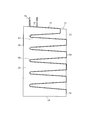
- the perspective view of the freezing apparatus which concerns on one Embodiment The right view of the inner box and refrigerant
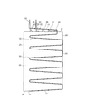
- coolant piping with which the refrigeration apparatus which concerns on other embodiment is provided.
- FIG. 1 is a perspective view of a refrigeration apparatus 1 according to an embodiment of the present invention as viewed obliquely from above and rearward.
- FIG. 2 is a right side view of the inner box 20, the first refrigerant pipe 50, and the second refrigerant pipe 60 provided in the refrigeration apparatus 1.
- the refrigeration apparatus 1 is, for example, a cryogenic freezer.
- the refrigeration apparatus 1 includes an outer box 10, an inner box 20, and a heat insulating box body that is configured by a heat insulating material (not shown) disposed therebetween.
- a door 30 is attached in front of the heat insulating box so as to be opened and closed.
- coolant liquefying apparatus 40 is arrange
- FIG. 1 is drawn so that the outer box 10, the door 30, and the refrigerant liquefying device 40 can be seen through and other members disposed therein can be seen.
- a leg or a base (not shown) that supports the heat insulation box is disposed below the heat insulation box.
- the inner box 20 has a cooling chamber with an opening at the front.
- the cooling chamber is surrounded by the inner box 20 on the upper side, the right side, the left side, the rear side, and the lower side.
- the right means the right side when viewed from the front side of the refrigeration apparatus 1
- the left means the left side when viewed from the front side of the refrigeration apparatus 1.
- the inner box 20 has a ceiling 21, a right side wall 22, a rear side wall 23, a left side wall (not shown), and a bottom 24.
- the ceiling 21 is inclined with respect to the horizontal plane.
- the right side wall 22, the rear side wall 23, and the left side wall are vertical.
- the right side wall 22 and the rear side wall 23 are orthogonal to each other in plan view.
- the left side wall and the rear side wall 23 are orthogonal to each other in plan view.
- the bottom 24 is horizontal.
- the refrigerant liquefying device 40 is a device capable of liquefying a refrigerant having a very low boiling point such as helium.
- the refrigerant liquefying device 40 is, for example, a Stirling refrigerator. However, it is not limited to a Stirling refrigerator as long as a refrigerant having a predetermined boiling point can be liquefied.
- a first refrigerant pipe 50 and a second refrigerant pipe 60 are disposed around the inner box 20.
- One end of the first refrigerant pipe 50 at the highest position of each refrigerant pipe and one end of the second refrigerant pipe 60 are connected to the refrigerant liquefaction device 40, respectively.
- the first refrigerant pipe 50 and the second refrigerant pipe 60 each constitute a thermosiphon.
- the first refrigerant pipe 50 has a first inclined part 51, a first lateral vertical part 52, and a first rear vertical part 53.
- the first inclined portion 51 is disposed directly above the inner box 20, specifically, directly above the ceiling 21.
- the ceiling 21 and the first inclined portion 51 are parallel to each other. That is, the first inclined portion 51 is inclined with respect to the horizontal plane.
- the first inclined portion 51 meanders so as to substantially cover the right half of the ceiling 21.
- the 1st inclination part 51 is attached to the ceiling 21 with the adhesive tape etc. which are not shown in figure so that the outer surface of the ceiling 21 may be contacted directly.
- the first inclined portion 51 is connected to the first lateral vertical portion 52 via a bent portion.
- the first side vertical portion 52 is disposed on the side of the inner box 20, specifically, on the right side of the right side wall 22.
- the right side wall 22 and the first side vertical portion 52 are parallel to each other.
- the first lateral vertical portion 52 is connected to the first rear vertical portion 53.
- the first rear vertical portion 53 is disposed behind the inner box 20, specifically, on the rear side of the rear side wall 23.
- the rear side wall 23 and the first rear vertical part 53 are parallel to each other.
- the first refrigerant pipe 50 meanders greatly between the right side of the right side wall 22 and the rear side of the rear side wall 23 so as to alternately form the first side vertical parts 52 and the first rear vertical parts 53. Each time it meanders, it is arranged to gradually extend downward. That is, the first side vertical part 52 and the first rear vertical part 53 are substantially orthogonal in plan view so as to follow the right side wall 22 and the rear side wall 23. In other words, the vertical portion composed of the first lateral vertical portion 52 and the first rear vertical portion 53 is bent at approximately 90 ° in plan view. Needless to say, when the angle formed by the right side wall 22 and the rear side wall 23 is changed, the angle is an angle according to the changed angle.
- the first side vertical part 52 and the first rear vertical part 53 are attached to the right side wall 22 and the rear side wall 23 with an adhesive tape (not shown) so as to directly contact the right side wall 22 and the rear side wall 23, respectively. .
- the second refrigerant pipe 60 has a second inclined portion 61, a second lateral vertical portion (not shown), and a second rear vertical portion 63.
- the second inclined portion 61 is disposed directly above the inner box 20, specifically, directly above the ceiling 21.
- the ceiling 21 and the second inclined portion 61 are parallel to each other. That is, the second inclined portion 61 is inclined with respect to the horizontal plane.
- the second inclined portion 61 meanders so as to substantially cover the left half of the ceiling 21.
- the 2nd inclination part 61 is attached to the ceiling 21 with the adhesive tape etc. which are not shown in figure so that it may contact the outer surface of the ceiling 21 directly.
- the second inclined portion 61 is connected to the second lateral vertical portion via a bent portion.
- the second side vertical portion is disposed on the side of the inner box 20, specifically, on the left side of the left side wall.
- the left side wall and the second lateral vertical portion are parallel to each other.
- the second side vertical part is connected to the second rear vertical part 63.
- the second rear vertical portion 63 is disposed behind the inner box 20, specifically, on the rear side of the rear side wall 23.
- the rear side wall 23 and the second rear vertical part 63 are parallel to each other.
- the second refrigerant pipe 60 meanders between the left side of the left side wall and the rear side of the rear side wall 23 so as to alternately form the second side vertical part and the second rear vertical part 63 and meanders. It is arranged so as to gradually extend downward each time. That is, the second side vertical part and the second rear vertical part 63 are substantially orthogonal in plan view so as to follow the left side wall and the rear side wall 23. In other words, the vertical portion composed of the second lateral vertical portion and the second rear vertical portion 63 is bent at approximately 90 ° in plan view. Needless to say, when the angle formed by the left side wall and the rear side wall 23 is changed, this angle becomes an angle according to the changed angle.
- the second side vertical part and the second rear vertical part 63 are attached to the left side wall and the rear side wall 23 with an adhesive tape (not shown) so as to directly contact the left side wall and the rear side wall 23, respectively.
- coolant stops in each other end (each end of the side which is not connected to the refrigerant
- the connection part 70 is connected. Therefore, the refrigerant can flow from one side to the other, and a sufficient cooling action can be obtained at each other end.
- the refrigeration apparatus 1 configured as described above operates as follows.
- the refrigerant liquefying device 40 liquefies the refrigerant and supplies the liquefied refrigerant to the first refrigerant pipe 50 and the second refrigerant pipe 60.
- the phenomenon that occurs mainly in and around the first refrigerant pipe 50 and the action thereof will be described.
- the same phenomenon occurs in the second refrigerant pipe 60 and around it, and the same action can be obtained.
- the refrigerant supplied to the first refrigerant pipe 50 flows downward in the first refrigerant pipe 50 by the action of gravity. At this time, the refrigerant exchanges heat with the inside of the cooling chamber via the first refrigerant pipe 50 and the inner box 20. That is, the liquid-phase refrigerant flows downward while exchanging heat. Therefore, the inside of the cooling chamber is cooled and the refrigerant is heated.
- the refrigerant When the temperature of the refrigerant exceeds the boiling point of the refrigerant, the refrigerant vaporizes. The inside of the cooling chamber is further cooled by the latent heat at this time.
- the vaporized refrigerant flows in the first refrigerant pipe 50 upward. When it reaches one end of the first refrigerant pipe 50, it is cooled again and liquefied by the refrigerant liquefier 40. The liquefied refrigerant again flows downward in the first refrigerant pipe 50.
- the first refrigerant pipe 50 has a first inclined portion 51.
- the first inclined portion 51 is inclined with respect to the horizontal plane. Accordingly, the refrigerant in the liquid phase can flow from a high position in the first inclined portion 51 to a low position, and the refrigerant in the gas phase can flow from a low position in the first inclined portion 51 to a high position. it can.
- the refrigerant flowing in the first inclined portion 51 can cool the inside of the cooling chamber from above the cooling chamber via the ceiling 21.
- a liquid phase that is, a refrigerant having a temperature lower than the boiling point of the refrigerant flows in the first inclined portion 51. Therefore, the inside of the cooling chamber can be cooled more effectively from above the cooling chamber.
- the first inclined portion 51 meanders so as to substantially cover the right half of the ceiling 21. Therefore, the inside of the cooling chamber can be evenly cooled from above the cooling chamber via the wide area of the ceiling 21.
- the first inclined portion 51 and the first lateral vertical portion 52 are connected via a bent portion.
- the bending angle of the bent portion is set to an angle that does not hinder the flow of the liquid-phase and gas-phase refrigerant. In particular, the angle is set so that bubbles formed by the gas-phase refrigerant do not stay. Therefore, the liquid-phase refrigerant that has flowed through the first inclined portion 51 can flow into the first lateral vertical portion 52 without any trouble. Further, the gas-phase refrigerant that has flowed through the first side vertical portion 52 can flow into the first inclined portion 51 without any trouble. Therefore, the refrigerant cooled by the refrigerant liquefier 40 can be supplied from one end of the first refrigerant pipe 50 to the other end. Further, it is possible to prevent a place where effective heat exchange cannot be performed.
- first side vertical part 52 and the first rear vertical part 53 meander so that the refrigerant alternates between the right side of the right side wall 22 and the rear side of the rear side wall 23 and gradually extends downward. doing. Therefore, the refrigerant can cool the cooling chamber equally from the two surfaces via the right side wall 22 and the rear side wall 23.
- the cooling chamber is uniformly cooled from the upper side, the right side, the rear side, and the left side. Therefore, it is possible to prevent the temperature distribution from being biased inside the cooling chamber.
- the ceiling 21 is inclined with respect to the horizontal plane. Specifically, the ceiling 21 is inclined so that the front becomes higher. That is, the cooling chamber is wider toward the front side (front side). Therefore, according to the present embodiment, the object to be cooled can be looked to the back without being blocked by the object to be cooled placed on the front side of the cooling chamber, and the object to be cooled placed on the back side.
- the advantage is that it is easier to reach out.
- FIG. 3 is a right side view of the inner box 20, the first refrigerant pipe 50, and the second refrigerant pipe 60 provided in the refrigeration apparatus 1 according to another embodiment.
- the ceiling 21 is horizontal.
- the 1st inclination part 51 and the 2nd inclination part 61 are inclined with respect to the horizontal surface similarly to previous embodiment. Therefore, there is a gap between the ceiling 21 and the first inclined portion 51 and the second inclined portion 61.
- Each support member 80 includes a leg portion 81 that supports the first inclined portion 51 or the second inclined portion 61 from below, and a base 82 that supports the leg portion 81 from below. That is, each support member 80 supports the first inclined portion 51 or the second inclined portion 61 from below.
- Each support member 80 is formed of a material having high thermal conductivity such as metal.
- Each leg portion 81 is in close contact with the first inclined portion 51 or the second inclined portion 61.
- Each base 82 is in close contact with the ceiling 21. Therefore, the refrigerant flowing through the first inclined portion 51 and the second inclined portion 61 can cool the cooling chamber via the support member 80.
- each support member 80 is not limited to the above-described shape and material as long as it can support the first inclined portion 51 and the second inclined portion 61 so as to be able to conduct heat.
- the bottom 24 is inclined with respect to the horizontal plane.
- the first refrigerant pipe 50 and the second refrigerant pipe 60 are respectively connected to a first rear vertical part 53 and a second rear vertical part 63 (see FIG. 1), and a second lower slope (not shown). Contains parts.
- the first downward inclined portion 54 and the second downward inclined portion are connected to the first rear vertical portion 53 and the second rear vertical portion 63 (see FIG. 1) via bent portions, respectively.
- the angles of these bent portions are the bent angle between the first inclined portion 51 and the first lateral vertical portion 52 and the second inclined portion 61 and the second lateral vertical in the previous embodiment, respectively. It is set in the same manner as the bending angle between the two parts. Therefore, the same effect can be obtained.
- the first downward inclined portion 54 and the second downward inclined portion are disposed directly below the inner box 20, specifically, directly below the bottom 24.
- the bottom 24 and the first downward inclined portion 54 are parallel to each other.
- the bottom 24 and the second downwardly inclined portion are parallel to each other. That is, the first downward inclined portion 54 and the second downward inclined portion are inclined with respect to the horizontal plane.
- the first downward inclined portion 54 meanders so as to substantially cover the right half of the bottom 24.
- the second downward inclined portion meanders so as to substantially cover the left half of the bottom 24.
- the first downward inclined portion 54 and the second downward inclined portion are attached to the bottom 24 with an adhesive tape (not shown) or the like so as to directly contact the outer surface of the bottom 24.
- connection part 70 The 1st refrigerant
- coolant piping 60 are connected in the connection part 70 similarly to previous embodiment.
- the refrigerant can also cool the cooling chamber through the bottom 24. Therefore, in this embodiment, the cooling chamber is uniformly cooled from the upper side, the right side, the rear side, the left side, and the lower side. Therefore, it is possible to more effectively prevent the temperature distribution from being biased inside the cooling chamber.
- the refrigeration apparatus 1 is not limited to a refrigerator, and may be a medical freezer, a showcase, a refrigerator / freezer warehouse, an ice maker, or the like.
- Both the ceiling 21 and the bottom 24 may be inclined. Both the ceiling 21 and the bottom 24 are horizontal, and are connected to the first inclined portion 51 and the second inclined portion 61, and the first downward inclined portion 54 and the second downward inclined portion, respectively, via a support member 80. May be.
- one refrigerant pipe includes an inclined portion disposed above the ceiling 21 and a vertical portion that meanders along the outer surfaces of the right side wall 22, the rear side wall 23, and the left side wall. .
- one refrigerant pipe has an inclined part arranged above the ceiling 21 and a vertical part arranged along the outer surface of the right side wall 22.
- the other refrigerant pipe has an inclined portion arranged above the ceiling 21 and a vertical portion arranged along the outer surface of the rear side wall 23.
- another refrigerant pipe has an inclined part arranged above the ceiling 21 and a vertical part arranged along the outer surface of the left side wall.
- the first inclined portion 51 and the second inclined portion 61 may not be parallel to the ceiling 21 inclined with respect to the horizontal plane. In this case, although a gap is generated between the ceiling 21 and the first inclined portion 51 and the second inclined portion 61, the ceiling 21 is supported by supporting the first inclined portion 51 and the second inclined portion 61 with the support member 80.
- the cooling chamber can be cooled from above.
- the first downward inclined portion 54 and the second downward inclined portion may not be parallel to the bottom 24 inclined with respect to the horizontal plane. In this case, although a gap is generated between the bottom 24 and the first downward inclined portion 54 and the second downward inclined portion, the first downward inclined portion 54 and the second downward inclined portion are supported by the support member 80, whereby the bottom The cooling chamber can be cooled from below via 24.
- the first lateral vertical portion 52, the first rear vertical portion 53, the second lateral vertical portion, or the second rear vertical portion 63 is connected to the right side wall through a member having good thermal conductivity such as the support member 80. 22 may be supported by the rear side wall 23 or the left side wall.
- the present invention is suitably used as a refrigeration apparatus for on / off control of a compressor.
Landscapes
- Engineering & Computer Science (AREA)
- Physics & Mathematics (AREA)
- Mechanical Engineering (AREA)
- Thermal Sciences (AREA)
- General Engineering & Computer Science (AREA)
- Chemical & Material Sciences (AREA)
- Combustion & Propulsion (AREA)
- Life Sciences & Earth Sciences (AREA)
- Sustainable Development (AREA)
- Devices That Are Associated With Refrigeration Equipment (AREA)
- Refrigerator Housings (AREA)
Abstract
冷凍装置は、冷却室を取り囲む内箱と、前記内箱よりも高い位置に配置された冷媒液化装置と、前記冷媒液化装置に接続され、且つ、水平面に対して傾斜した状態で前記内箱の真上に配置された傾斜部を有する冷媒配管と、を備える。
Description
本発明は、冷凍装置に関する。
従来、例えば特許文献1に記載されているように、スターリング冷凍機とサーモサイフォンを備える冷凍装置が提案されている。
サーモサイフォンを備える冷凍装置においては、冷媒は重力を利用してサーモサイフォン内を移動する。そのため、サーモサイフォンは、冷却室を取り囲む内箱の鉛直な側面に沿うように配置されている。よって、サーモサイフォンを備える冷凍装置においては、内箱の側面が冷媒によって冷却される。言い換えると、内箱に取り囲まれている冷却室の内部は、内箱側面に近い部分が他の部分よりも強く冷却される。つまり、冷却室内は、均等に冷却されない。
本発明は、このような状況に鑑みなされたものであり、冷却室内を均等に冷却することが可能な冷凍装置を提供することを課題とする。
本発明に係る冷凍装置は、冷却室を取り囲む内箱と、前記内箱よりも高い位置に配置された冷媒液化装置と、前記冷媒液化装置に接続され、且つ、水平面に対して傾斜した状態で前記内箱の真上に配置された傾斜部を有する冷媒配管と、を備える。
本発明によれば、冷却室内を均等に冷却することが可能な冷凍装置を提供することができる。
以下、本発明の実施形態について、図面を参照しつつ詳細に説明する。
図1は、本発明の一実施形態に係る冷凍装置1を後方斜め上方から見た斜視図である。また、図2は、冷凍装置1が備える内箱20、第1冷媒配管50、及び第2冷媒配管60の右側面図である。なお、冷凍装置1は、例えば、極低温フリーザーである。
冷凍装置1は、外箱10、内箱20及びこれらの間に配置された図示しない断熱材によって構成された断熱箱体を備えている。この断熱箱体の前方には、扉30が開閉可能に取り付けられている。また、断熱箱体よりも高い位置には、冷媒液化装置40が配置されている。なお、説明の便宜上、図1は、外箱10、扉30及び冷媒液化装置40が透視されてそれらの内部に配置された他の部材が見えるように描かれている。なお、断熱箱体の下方には、断熱箱体を支持する図示しない脚または台が配置されている。
内箱20は、その内部に、前方が開口した冷却室を有している。言い換えると、冷却室は内箱20によって、上方、右側方、左側方、後方及び下方を取り囲まれている。なお、特に断らない限り、本明細書において、右とは、冷凍装置1の前方側から見て右側を意味し、左とは、冷凍装置1の前方側から見て左側を意味する。
内箱20は、天井21、右側壁22、後側壁23、図示されない左側壁、及び、底24を有している。
天井21は、水平面に対して傾斜している。
右側壁22、後側壁23、及び、左側壁は、鉛直である。右側壁22と後側壁23は、平面視において互いに直交している。左側壁と後側壁23は、平面視において互いに直交している。
底24は、水平である。
冷媒液化装置40は、ヘリウム等の沸点が極低温である冷媒を液化することが可能な装置である。冷媒液化装置40は、例えば、スターリング冷凍機である。但し、所定の沸点を有する冷媒を液化することができれば、スターリング冷凍機には限られない。
内箱20の周囲には、第1冷媒配管50と第2冷媒配管60が配置されている。各冷媒配管の最も高い位置にある第1冷媒配管50の一端、及び、第2冷媒配管60の一端は、それぞれ、冷媒液化装置40に接続されている。第1冷媒配管50及び第2冷媒配管60は、それぞれサーモサイフォンを構成する。
第1冷媒配管50は、第1傾斜部51、第1側方鉛直部52、及び、第1後方鉛直部53を有する。
第1傾斜部51は、内箱20の真上、具体的には、天井21の真上に配置されている。天井21と第1傾斜部51は、互いに平行である。すなわち、第1傾斜部51は、水平面に対して傾斜している。
第1傾斜部51は、天井21の右側半分を略覆うように、蛇行している。第1傾斜部51は、天井21の外面に直接接触するように、図示しない粘着テープ等で天井21に取り付けられている。
第1傾斜部51は、第1側方鉛直部52に、屈曲部を介して接続されている。第1側方鉛直部52は、内箱20の側方、具体的には、右側壁22の右側に配置されている。右側壁22と第1側方鉛直部52は、互いに平行である。
第1側方鉛直部52は、第1後方鉛直部53に接続されている。第1後方鉛直部53は、内箱20の後方、具体的には、後側壁23の後側に配置されている。後側壁23と第1後方鉛直部53は、互いに平行である。
第1冷媒配管50は、第1側方鉛直部52と第1後方鉛直部53とを交互に形成するように、右側壁22の右側と後側壁23の後側との間で大きく蛇行するとともに、蛇行する毎に、徐々に下方に伸びるように配置されている。すなわち、第1側方鉛直部52と、第1後方鉛直部53は、右側壁22と後側壁23に沿うように、平面視において略直交している。言い換えると、第1側方鉛直部52と第1後方鉛直部53とからなる鉛直部は、平面視において略90°に折れ曲がっている。この角度は、右側壁22と後側壁23がなす角度が変更された場合、当該変更後の角度に準じた角度になることは言うまでもない。
第1側方鉛直部52及び第1後方鉛直部53は、それぞれ、右側壁22及び後側壁23に直接接触するように、図示しない粘着テープ等で右側壁22及び後側壁23に取り付けられている。
第2冷媒配管60は、第2傾斜部61、図示しない第2側方鉛直部、及び、第2後方鉛直部63を有する。
第2傾斜部61は、内箱20の真上、具体的には、天井21の真上に配置されている。天井21と第2傾斜部61は、互いに平行である。すなわち、第2傾斜部61は、水平面に対して傾斜している。
第2傾斜部61は、天井21の左側半分を略覆うように、蛇行している。第2傾斜部61は、天井21の外面に直接接触するように、図示しない粘着テープ等で天井21に取り付けられている。
第2傾斜部61は、第2側方鉛直部に、屈曲部を介して接続されている。第2側方鉛直部は、内箱20の側方、具体的には、左側壁の左側に配置されている。左側壁と第2側方鉛直部は、互いに平行である。
第2側方鉛直部は、第2後方鉛直部63に接続されている。第2後方鉛直部63は、内箱20の後方、具体的には、後側壁23の後側に配置されている。後側壁23と第2後方鉛直部63は、互いに平行である。
第2冷媒配管60は、第2側方鉛直部と第2後方鉛直部63とを交互に形成するように、左側壁の左側と後側壁23の後側との間で大きく蛇行するとともに、蛇行する毎に、徐々に下方に伸びるように配置されている。すなわち、第2側方鉛直部と、第2後方鉛直部63は、左側壁と後側壁23に沿うように、平面視において略直交している。言い換えると、第2側方鉛直部と第2後方鉛直部63とからなる鉛直部は、平面視において略90°に折れ曲がっている。この角度は、左側壁と後側壁23がなす角度が変更された場合、当該変更後の角度に準じた角度になることは言うまでもない。
第2側方鉛直部及び第2後方鉛直部63は、それぞれ、左側壁及び後側壁23に直接接触するように、図示しない粘着テープ等で左側壁及び後側壁23に取り付けられている。
第1冷媒配管50と第2冷媒配管60は、それぞれの他端(冷媒液化装置40に接続されていない側の各端)で冷媒の流れが止まり、各他端近傍での冷却作用が弱まることを防ぐため、接続部70において接続されている。よって、冷媒が一方から他方へ向けて流通でき、各他端においても十分な冷却作用を得ることができる。
以上のように構成された冷凍装置1は、次のように作動する。
冷媒液化装置40は、冷媒を液化し、液化された冷媒を第1冷媒配管50及び第2冷媒配管60に供給する。以下、主に第1冷媒配管50内及びその周辺で起きる現象並びにそれらの作用について説明するが、第2冷媒配管60内及びその周辺でも同様の現象が起き、同様の作用が得られる。
第1冷媒配管50に供給された冷媒は、重力の作用によって、第1冷媒配管50の内部を下方に向けて流れていく。この際、冷媒は、第1冷媒配管50及び内箱20を介して、冷却室の内部と熱交換する。すなわち、液相の冷媒は、熱交換しながら下方に向けて流れていく。よって、冷却室の内部は冷却され、冷媒は加熱される。
冷媒の温度が冷媒の沸点を超えると、冷媒は気化する。このときの潜熱によって、冷却室の内部はさらに冷却される。
気化した冷媒は、第1冷媒配管50内を上方に向けて流れていく。第1冷媒配管50の一端に達すると、冷媒液化装置40によって、再び冷却され、液化される。液化された冷媒は、再び、第1冷媒配管50の内部を下方に向けて流れていく。
このような冷媒の流通及び相変化が繰り返されることによって、冷却室の内部は目標温度に冷却される。
本実施形態においては、第1冷媒配管50は第1傾斜部51を有している。第1傾斜部51は、水平面に対して傾斜している。よって、液相状態の冷媒は、第1傾斜部51内の高い位置から低い位置に流れることができ、気相状態の冷媒は、第1傾斜部51内の低い位置から高い位置に流れることができる。
よって、第1傾斜部51内を流れる冷媒は、天井21を介して、冷却室の内部を冷却室の上方から冷却することができる。
しかも、第1傾斜部51内を、液相、つまり、冷媒の沸点よりも温度が低い冷媒が流れる。よって、より効果的に、冷却室の内部を冷却室の上方から冷却することができる。
さらに、第1傾斜部51は、天井21の右側半分を略覆うように蛇行している。よって、天井21の広い領域を介して、冷却室の内部を冷却室の上方から均等に冷却することができる。
また、本実施形態においては、第1傾斜部51と第1側方鉛直部52とは、屈曲部を介して接続されている。この屈曲部の屈曲角度は、液相及び気相の冷媒の流通が妨げられない角度に設定されている。特に、気相の冷媒によって形成される気泡が滞留しない角度に設定されている。よって、第1傾斜部51内を流れた液相の冷媒は、何ら支障なく第1側方鉛直部52内に流れ込むことができる。また、第1側方鉛直部52内を流れた気相の冷媒は、何ら支障なく第1傾斜部51内に流れ込むことができる。従って、第1冷媒配管50の一端から他端まで、冷媒液化装置40で冷却された冷媒を供給することができる。また、有効な熱交換ができない場所が生じることを防ぐことができる。
しかも、第1側方鉛直部52と第1後方鉛直部53は、冷媒が右側壁22の右側と後側壁23の後側を交互に行き来するように、且つ、徐々に下方に伸びるように蛇行している。よって、冷媒は、右側壁22及び後側壁23を介して、2つの面から均等に冷却室を冷却することができる。
したがって、本実施形態においては、冷却室は、その上方、右側方、後側方、及び、左側方から均等に冷却される。よって、冷却室の内部に温度分布の偏りが生じることを防ぐことができる。
また、本実施形態においては、天井21が水平面に対して傾斜している。具体的には、前方が高くなるように天井21が傾斜している。すなわち、冷却室内は手前側(前方側)ほど広くなっている。よって、本実施形態によれば、冷却室の手前側に載置されている被冷却物に視界を遮られることなく、奥まで見渡すことができるとともに、奥側に載置されている被冷却物に手を伸ばしやすくなるという利点が得られる。
続いて、他の実施形態について、先の実施形態とは異なる点を中心に説明する。図3は、他の実施形態に係る冷凍装置1が備える内箱20、第1冷媒配管50、及び第2冷媒配管60の右側面図である。
天井21は、水平である。第1傾斜部51及び第2傾斜部61は、先の実施形態と同様、水平面に対して傾斜している。よって、天井21と第1傾斜部51及び第2傾斜部61との間には隙間がある。
本実施形態においては、複数の支持部材80が天井21の上に配置されている。各支持部材80は、第1傾斜部51または第2傾斜部61を下方から支持する脚部81と、脚部81を下方から支持するベース82とから構成されている。すなわち、各支持部材80は第1傾斜部51または第2傾斜部61を下方から支持している。
各支持部材80は、金属等、熱伝導率が高い素材で形成されている。各脚部81は、第1傾斜部51または第2傾斜部61に密着している。各ベース82は、天井21に密着している。よって、第1傾斜部51及び第2傾斜部61の内部を流通する冷媒は、支持部材80を介して、冷却室を冷却することができる。
なお、各支持部材80は、第1傾斜部51及び第2傾斜部61を熱伝導可能に支持することが可能のものであれば、上述の形状及び素材に限られないことは言うまでもない。
また、本実施形態においては、底24は、水平面に対して傾斜している。
第1冷媒配管50及び第2冷媒配管60は、それぞれ、第1後方鉛直部53及び第2後方鉛直部63(図1参照)に接続される第1下方傾斜部54及び図示されない第2下方傾斜部を含んでいる。
第1下方傾斜部54及び第2下方傾斜部は、それぞれ、第1後方鉛直部53及び第2後方鉛直部63(図1参照)に、屈曲部を介して接続されている。なお、これらの屈曲部の角度は、それぞれ、先の実施形態における第1傾斜部51と第1側方鉛直部52との間の屈曲角度、及び、第2傾斜部61と第2側方鉛直部との間の屈曲角度と同様に設定されている。よって、同様の効果が得られる。
第1下方傾斜部54及び第2下方傾斜部は、内箱20の真下、具体的には、底24の真下に配置されている。底24と第1下方傾斜部54は、互いに平行である。底24と第2下方傾斜部は、互いに平行である。すなわち、第1下方傾斜部54及び第2下方傾斜部は、水平面に対して傾斜している。
第1下方傾斜部54は、底24の右側半分を略覆うべく、蛇行している。第2下方傾斜部は、底24の左側半分を略覆うべく、蛇行している。第1下方傾斜部54及び第2下方傾斜部は、底24の外面に直接接触するように、図示しない粘着テープ等で底24に取り付けられている。
第1冷媒配管50と第2冷媒配管60は、先の実施形態と同様に、接続部70において接続されている。
以上のように第1冷媒配管50及び第2冷媒配管60が配置されている本実施形態においては、冷媒は、底24を介しても、冷却室を冷却することができる。したがって、本実施形態においては、冷却室は、その上方、右側方、後側方、左側方、及び、下方から均等に冷却される。よって、冷却室の内部に温度分布の偏りが生じることをより効果的に防ぐことができる。
なお、本発明が、先に説明された各実施形態には限定されず、その要旨を逸脱しない範囲で種々の変形や応用が可能であることは言うまでもない。
例えば、本発明に係る冷凍装置1は、保冷庫には限られず、メディカルフリーザ、ショーケース、冷凍冷蔵倉庫又は製氷機等であってもよい。
天井21と底24の両方が傾斜していても良い。天井21と底24の両方が水平であり、それぞれ、支持部材80を介して第1傾斜部51及び第2傾斜部61、並びに、第1下方傾斜部54及び第2下方傾斜部に接続されていても良い。
冷媒配管の数は2つには限られず、1本であっても3本以上であってもよい。冷媒配管が1本の場合、1本の冷媒配管は、天井21の上方に配置される傾斜部と、右側壁22、後側壁23及び左側壁の外面に沿って大きく蛇行する鉛直部とを含む。
冷媒配管の数が3本の場合は、1本の冷媒配管が、天井21の上方に配置される傾斜部と、右側壁22の外面に沿って配置される鉛直部を有する。また、他の1本の冷媒配管が、天井21の上方に配置される傾斜部と、後側壁23の外面に沿って配置される鉛直部を有する。また、さらに他の1本の冷媒配管が、天井21の上方に配置される傾斜部と、左側壁の外面に沿って配置される鉛直部を有する。
第1傾斜部51及び第2傾斜部61は、水平面に対して傾斜する天井21と平行でなくてもよい。この場合、天井21と第1傾斜部51及び第2傾斜部61との間に隙間が生じるものの、第1傾斜部51及び第2傾斜部61を支持部材80で支持することにより、天井21を介して冷却室を上方から冷却することができる。
第1下方傾斜部54及び第2下方傾斜部は、水平面に対して傾斜する底24と平行でなくてもよい。この場合、底24と第1下方傾斜部54及び第2下方傾斜部との間に隙間が生じるものの、第1下方傾斜部54及び第2下方傾斜部を支持部材80で支持することにより、底24を介して冷却室を下方から冷却することができる。
第1側方鉛直部52、第1後方鉛直部53、第2側方鉛直部、又は、第2後方鉛直部63は、支持部材80のような熱伝導性の良い部材を介して、右側壁22、後側壁23、又は、左側壁に支持されていても良い。
2018年3月6日出願の特願2018-039701の日本出願に含まれる明細書、特許請求の範囲、図面および要約書の開示内容は、すべて本願に援用される。
本発明は、圧縮機をオンオフ制御する冷凍装置として好適に利用される。
1 冷凍装置
10 外箱
20 内箱
21 天井
22 右側壁
23 後側壁
24 底
30 扉
40 冷媒液化装置
50 第1冷媒配管
51 第1傾斜部
52 第1側方鉛直部
53 第1後方鉛直部
54 第1下方傾斜部
60 第2冷媒配管
61 第2傾斜部
63 第2後方鉛直部
70 接続部
80 支持部材
81 脚部
82 ベース
10 外箱
20 内箱
21 天井
22 右側壁
23 後側壁
24 底
30 扉
40 冷媒液化装置
50 第1冷媒配管
51 第1傾斜部
52 第1側方鉛直部
53 第1後方鉛直部
54 第1下方傾斜部
60 第2冷媒配管
61 第2傾斜部
63 第2後方鉛直部
70 接続部
80 支持部材
81 脚部
82 ベース
Claims (11)
- 冷却室を取り囲む内箱と、
前記内箱よりも高い位置に配置された冷媒液化装置と、
前記冷媒液化装置に接続され、且つ、水平面に対して傾斜した状態で前記内箱の真上に配置された傾斜部を有する冷媒配管と、
を備える、冷凍装置。 - 前記内箱の天井は水平面に対して傾斜している、
請求項1に記載の冷凍装置。 - 前記内箱の天井と前記傾斜部は、互いに平行である、
請求項2に記載の冷凍装置。 - 前記傾斜部は、前記内箱の天井に接触している、
請求項1から3のいずれかに記載の冷凍装置。 - 伝熱部材をさらに備え、
前記内箱の天井は水平であり、
前記傾斜部は、前記伝熱部材を介して前記内箱の天井に支持されている、
請求項1に記載の冷凍装置。 - 前記傾斜部は蛇行している、
請求項1から5のいずれかに記載の冷凍装置。 - 前記冷媒配管を複数有する、
請求項1から6のいずれかに記載の冷凍装置。 - 前記冷媒配管は、前記傾斜部に接続され、且つ、鉛直面に対して平行に配置された鉛直部を含む、
請求項1から7のいずれかに記載の冷凍装置。 - 前記鉛直部は、前記内箱の2以上の側面に沿うように配置され、平面視において所定角度に折れ曲がっている、
請求項8に記載の冷凍装置。 - 前記冷媒配管は、水平面に対して傾斜した状態で前記内箱の真下に配置された下方傾斜部を含む、
請求項1から9のいずれかに記載の冷凍装置。 - 前記傾斜部は、液相の冷媒を流通させる、
請求項1から10のいずれかに記載の冷凍装置。
Priority Applications (3)
| Application Number | Priority Date | Filing Date | Title |
|---|---|---|---|
| JP2020504931A JP6851540B2 (ja) | 2018-03-06 | 2019-02-25 | 冷凍装置 |
| CN201980006563.2A CN111492191A (zh) | 2018-03-06 | 2019-02-25 | 冷冻装置 |
| US17/007,487 US20200400367A1 (en) | 2018-03-06 | 2020-08-31 | Refrigeration device |
Applications Claiming Priority (2)
| Application Number | Priority Date | Filing Date | Title |
|---|---|---|---|
| JP2018-039701 | 2018-03-06 | ||
| JP2018039701 | 2018-03-06 |
Related Child Applications (1)
| Application Number | Title | Priority Date | Filing Date |
|---|---|---|---|
| US17/007,487 Continuation US20200400367A1 (en) | 2018-03-06 | 2020-08-31 | Refrigeration device |
Publications (1)
| Publication Number | Publication Date |
|---|---|
| WO2019172001A1 true WO2019172001A1 (ja) | 2019-09-12 |
Family
ID=67845638
Family Applications (1)
| Application Number | Title | Priority Date | Filing Date |
|---|---|---|---|
| PCT/JP2019/006997 Ceased WO2019172001A1 (ja) | 2018-03-06 | 2019-02-25 | 冷凍装置 |
Country Status (4)
| Country | Link |
|---|---|
| US (1) | US20200400367A1 (ja) |
| JP (1) | JP6851540B2 (ja) |
| CN (1) | CN111492191A (ja) |
| WO (1) | WO2019172001A1 (ja) |
Citations (9)
| Publication number | Priority date | Publication date | Assignee | Title |
|---|---|---|---|---|
| JPS59152375U (ja) * | 1983-03-31 | 1984-10-12 | 株式会社東芝 | 冷蔵庫 |
| JPS624308A (ja) * | 1985-06-29 | 1987-01-10 | Toshiba Corp | 極低温装置 |
| JPH04126973A (ja) * | 1990-09-18 | 1992-04-27 | Toshiba Corp | 電子冷蔵庫 |
| JP2005156011A (ja) * | 2003-11-25 | 2005-06-16 | Twinbird Corp | サーモサイフォン |
| JP2005308357A (ja) * | 2004-04-23 | 2005-11-04 | Twinbird Corp | サーモサイフォン |
| CN104180586A (zh) * | 2013-05-22 | 2014-12-03 | 海尔集团公司 | 一种低温冰箱低温端的热管传热系统 |
| CN104329827A (zh) * | 2014-03-28 | 2015-02-04 | 海尔集团公司 | 一种热交换装置及半导体冰箱 |
| CN106766502A (zh) * | 2016-11-22 | 2017-05-31 | 上海理工大学 | 分体式一拖二斯特林制冷的变温区冰箱 |
| JP6224676B2 (ja) * | 2015-11-12 | 2017-11-01 | 日本フリーザー株式会社 | 並列分散型冷却システム |
Family Cites Families (7)
| Publication number | Priority date | Publication date | Assignee | Title |
|---|---|---|---|---|
| US3990262A (en) * | 1975-12-08 | 1976-11-09 | General Electric Company | Natural draft refrigerator including apparatus for permitting the condenser to move between a shipping position and an in-use position |
| US4459813A (en) * | 1982-09-13 | 1984-07-17 | Petta John R | Levelling apparatus for vehicle mounted refrigerator |
| DE3420256A1 (de) * | 1984-05-30 | 1985-12-05 | Martin A. Prof. Dipl.-Ing. 5060 Bergisch Gladbach Frank | Verfahren und vorrichtung zur kuehlung in containern |
| CN105940280B (zh) * | 2014-01-28 | 2019-07-16 | 弗诺尼克设备公司 | 用于减轻热虹吸管蒸发器或冷凝器中的高热通量状况的机构 |
| KR20170034997A (ko) * | 2015-09-21 | 2017-03-30 | 엘지전자 주식회사 | 냉장고 |
| CN105222471A (zh) * | 2015-10-27 | 2016-01-06 | 合肥华凌股份有限公司 | 制冷系统及具有它的冷柜 |
| US10718558B2 (en) * | 2017-12-11 | 2020-07-21 | Global Cooling, Inc. | Independent auxiliary thermosiphon for inexpensively extending active cooling to additional freezer interior walls |
-
2019
- 2019-02-25 WO PCT/JP2019/006997 patent/WO2019172001A1/ja not_active Ceased
- 2019-02-25 JP JP2020504931A patent/JP6851540B2/ja active Active
- 2019-02-25 CN CN201980006563.2A patent/CN111492191A/zh active Pending
-
2020
- 2020-08-31 US US17/007,487 patent/US20200400367A1/en not_active Abandoned
Patent Citations (9)
| Publication number | Priority date | Publication date | Assignee | Title |
|---|---|---|---|---|
| JPS59152375U (ja) * | 1983-03-31 | 1984-10-12 | 株式会社東芝 | 冷蔵庫 |
| JPS624308A (ja) * | 1985-06-29 | 1987-01-10 | Toshiba Corp | 極低温装置 |
| JPH04126973A (ja) * | 1990-09-18 | 1992-04-27 | Toshiba Corp | 電子冷蔵庫 |
| JP2005156011A (ja) * | 2003-11-25 | 2005-06-16 | Twinbird Corp | サーモサイフォン |
| JP2005308357A (ja) * | 2004-04-23 | 2005-11-04 | Twinbird Corp | サーモサイフォン |
| CN104180586A (zh) * | 2013-05-22 | 2014-12-03 | 海尔集团公司 | 一种低温冰箱低温端的热管传热系统 |
| CN104329827A (zh) * | 2014-03-28 | 2015-02-04 | 海尔集团公司 | 一种热交换装置及半导体冰箱 |
| JP6224676B2 (ja) * | 2015-11-12 | 2017-11-01 | 日本フリーザー株式会社 | 並列分散型冷却システム |
| CN106766502A (zh) * | 2016-11-22 | 2017-05-31 | 上海理工大学 | 分体式一拖二斯特林制冷的变温区冰箱 |
Also Published As
| Publication number | Publication date |
|---|---|
| JPWO2019172001A1 (ja) | 2020-10-22 |
| CN111492191A (zh) | 2020-08-04 |
| JP6851540B2 (ja) | 2021-03-31 |
| US20200400367A1 (en) | 2020-12-24 |
Similar Documents
| Publication | Publication Date | Title |
|---|---|---|
| JP6107954B2 (ja) | 保冷庫 | |
| WO2014112343A1 (ja) | 極低温装置及びこれを用いた被冷却体の冷却方法 | |
| KR20090077800A (ko) | 고온 연결 부재 및 저온 연결 부재를 구비하고 상기 연결 부재들에 연결되는 열교환 튜브를 구비하는 냉각 설비 | |
| EP2522936A1 (en) | Refrigerator | |
| JP2009150588A (ja) | 冷却装置 | |
| JPWO2010092628A1 (ja) | 冷蔵庫 | |
| JP6224676B2 (ja) | 並列分散型冷却システム | |
| JP6851540B2 (ja) | 冷凍装置 | |
| CN104034076A (zh) | 超低温冷却装置 | |
| US11047627B2 (en) | Cooling device | |
| JP6912673B2 (ja) | デフロストシステム | |
| JP2021508365A (ja) | 冷凍庫の他の内壁に積極的な冷却を安価に延伸するための独立した補助サーモサイフォン(Independentauxiliary thermosiphonfor inexpensivelyextending activecooling toadditional freezerinterior walls) | |
| JP2023070202A (ja) | 冷蔵庫 | |
| JP2018105561A (ja) | 冷蔵庫 | |
| JP2016220933A (ja) | 冷凍・冷蔵ショーケース | |
| JP5456415B2 (ja) | 冷凍ショーケース | |
| US11933544B2 (en) | Refrigeration device | |
| JP2024106756A (ja) | 冷却装置 | |
| CN216080516U (zh) | 冷藏柜 | |
| US11674732B2 (en) | Refrigerator | |
| JP2024106755A (ja) | 冷却装置 | |
| JP2018096647A (ja) | 冷蔵庫 | |
| JP4001607B2 (ja) | スターリング冷却庫 | |
| JP2005283022A (ja) | 蒸発器、サーモサイフォン及びスターリング冷却庫 | |
| JP2024106757A (ja) | 冷却装置 |
Legal Events
| Date | Code | Title | Description |
|---|---|---|---|
| 121 | Ep: the epo has been informed by wipo that ep was designated in this application |
Ref document number: 19764016 Country of ref document: EP Kind code of ref document: A1 |
|
| ENP | Entry into the national phase |
Ref document number: 2020504931 Country of ref document: JP Kind code of ref document: A |
|
| NENP | Non-entry into the national phase |
Ref country code: DE |
|
| 122 | Ep: pct application non-entry in european phase |
Ref document number: 19764016 Country of ref document: EP Kind code of ref document: A1 |