WO2019171723A1 - Imaging device and imaging unit - Google Patents
Imaging device and imaging unit Download PDFInfo
- Publication number
- WO2019171723A1 WO2019171723A1 PCT/JP2018/047962 JP2018047962W WO2019171723A1 WO 2019171723 A1 WO2019171723 A1 WO 2019171723A1 JP 2018047962 W JP2018047962 W JP 2018047962W WO 2019171723 A1 WO2019171723 A1 WO 2019171723A1
- Authority
- WO
- WIPO (PCT)
- Prior art keywords
- accessory
- filter body
- filter
- attached
- neutral density
- Prior art date
Links
Images


Classifications
-
- H—ELECTRICITY
- H04—ELECTRIC COMMUNICATION TECHNIQUE
- H04N—PICTORIAL COMMUNICATION, e.g. TELEVISION
- H04N23/00—Cameras or camera modules comprising electronic image sensors; Control thereof
- H04N23/60—Control of cameras or camera modules
- H04N23/69—Control of means for changing angle of the field of view, e.g. optical zoom objectives or electronic zooming
-
- G—PHYSICS
- G03—PHOTOGRAPHY; CINEMATOGRAPHY; ANALOGOUS TECHNIQUES USING WAVES OTHER THAN OPTICAL WAVES; ELECTROGRAPHY; HOLOGRAPHY
- G03B—APPARATUS OR ARRANGEMENTS FOR TAKING PHOTOGRAPHS OR FOR PROJECTING OR VIEWING THEM; APPARATUS OR ARRANGEMENTS EMPLOYING ANALOGOUS TECHNIQUES USING WAVES OTHER THAN OPTICAL WAVES; ACCESSORIES THEREFOR
- G03B17/00—Details of cameras or camera bodies; Accessories therefor
- G03B17/02—Bodies
- G03B17/12—Bodies with means for supporting objectives, supplementary lenses, filters, masks, or turrets
- G03B17/14—Bodies with means for supporting objectives, supplementary lenses, filters, masks, or turrets interchangeably
-
- H—ELECTRICITY
- H04—ELECTRIC COMMUNICATION TECHNIQUE
- H04N—PICTORIAL COMMUNICATION, e.g. TELEVISION
- H04N23/00—Cameras or camera modules comprising electronic image sensors; Control thereof
- H04N23/50—Constructional details
- H04N23/51—Housings
-
- H—ELECTRICITY
- H04—ELECTRIC COMMUNICATION TECHNIQUE
- H04N—PICTORIAL COMMUNICATION, e.g. TELEVISION
- H04N23/00—Cameras or camera modules comprising electronic image sensors; Control thereof
- H04N23/50—Constructional details
- H04N23/55—Optical parts specially adapted for electronic image sensors; Mounting thereof
-
- H—ELECTRICITY
- H04—ELECTRIC COMMUNICATION TECHNIQUE
- H04N—PICTORIAL COMMUNICATION, e.g. TELEVISION
- H04N23/00—Cameras or camera modules comprising electronic image sensors; Control thereof
- H04N23/60—Control of cameras or camera modules
-
- G—PHYSICS
- G03—PHOTOGRAPHY; CINEMATOGRAPHY; ANALOGOUS TECHNIQUES USING WAVES OTHER THAN OPTICAL WAVES; ELECTROGRAPHY; HOLOGRAPHY
- G03B—APPARATUS OR ARRANGEMENTS FOR TAKING PHOTOGRAPHS OR FOR PROJECTING OR VIEWING THEM; APPARATUS OR ARRANGEMENTS EMPLOYING ANALOGOUS TECHNIQUES USING WAVES OTHER THAN OPTICAL WAVES; ACCESSORIES THEREFOR
- G03B11/00—Filters or other obturators specially adapted for photographic purposes
Definitions
- This technology relates to the technical field of an imaging device and an imaging unit in which accessories can be attached to and detached from the mount portion.
- Various imaging devices such as a video camera and a still camera have an accessory such as an interchangeable lens that can be attached to and detached from the mount portion.
- an accessory such as an interchangeable lens that can be attached to and detached from the mount portion.
- the interchangeable lens may be attached to the mount portion via an adapter, and the adapter is also used as an accessory in the imaging device (see, for example, Patent Document 1).
- an optical function unit having various functions such as a filter and an image sensor is disposed inside the casing, and the optical performance of these optical function units is ensured. It is necessary to improve the quality of the captured image.
- the image quality can be improved by ensuring good optical performance even when any accessory is attached to the mount unit. It is desirable that it be planned.
- the imaging device and the imaging unit of the present technology have an object of overcoming the above-described problems and ensuring good optical performance to improve image quality.
- an imaging apparatus includes a housing having a mount portion to which at least a first accessory and a second accessory are selectively attached, and an imaging element that photoelectrically converts captured light into an electrical signal. And a first mount surface to which the first accessory is attached and a second mount surface to which the second accessory is attached are formed on the mount portion, and the first mount surface and the first mount The two mounting surfaces are located on the same plane.
- first accessory and the second accessory are selectively attached to the first mount surface and the second mount surface located on the same plane, respectively.
- the first mount surface and the second mount surface are formed as a part of the same member.
- first mount surface and the second mount surface are formed on the same member.
- a contact is provided to which a terminal of the first accessory is connected in a state where the first accessory is attached to the first mount surface, It is preferable that the contact is shielded by the second accessory in a state where the second accessory is attached to the second mount surface.
- a positioning unit that positions the first accessory and the second accessory in a direction orthogonal to the optical axis may be formed in the housing. desirable.
- the positioning in the direction orthogonal to the optical axis of the first accessory and the second accessory with respect to the housing is performed by one positioning unit.
- the first filter body having at least one neutral density filter that is positioned on the optical axis and reduces the amount of light directed to the imaging device, and the optical axis And a second filter body having at least one neutral density filter that is positioned apart from the first filter body and reduces the amount of light directed to the imaging device. It is desirable that the first filter body and the image sensor are positioned on the opposite side of the image sensor, and the neutral density filter having the lowest optical density among the neutral density filters is provided on the first filter body.
- the first filter body provided with the neutral density filter having the lowest optical density is positioned on the opposite side of the image sensor with the second filter body interposed therebetween.
- an infrared cut filter is disposed on the opposite side of the second filter body with the first filter body interposed therebetween.
- the first filter body and the second filter body are respectively rotatable, and the first filter body and the second filter body are respectively rotated. It is desirable to provide a plurality of the neutral density filters that have different optical densities and are spaced apart in the circumferential direction.
- This increases the number of combinations of neutral density filters having different optical densities by rotating the first filter body and the second filter body.
- an imaging unit includes a housing having a mount portion to which at least a first accessory and a second accessory are selectively attached, and electric light that is arranged and captured inside the housing.
- An image sensor that performs photoelectric conversion to a target signal, and the mount portion includes a first mount surface to which the first accessory is attached and a second mount surface to which the second accessory is attached, The first mount surface and the second mount surface are located on the same plane.
- first accessory and the second accessory are selectively attached to the first mount surface and the second mount surface located on the same plane, respectively.
- another imaging apparatus includes an imaging element that photoelectrically converts captured light into an electrical signal, and at least one that reduces an amount of light that is located on an optical axis and travels toward the imaging element.
- Two filter bodies, and the first filter body and the image sensor are positioned on the opposite side of the second filter body, and the first filter body is the most optical of the neutral density filters.
- a neutral density filter having a low density is provided.
- the first filter body provided with the neutral density filter having the lowest optical density is positioned on the opposite side of the image sensor with the second filter body interposed therebetween.
- an infrared cut filter be disposed on the opposite side of the second filter body with the first filter body interposed therebetween.
- the first filter body and the second filter body can be rotated, respectively, and the first filter body and the second filter body can be rotated.
- a plurality of neutral density filters having different optical densities and spaced apart in the circumferential direction are provided.
- This increases the number of combinations of neutral density filters having different optical densities by rotating the first filter body and the second filter body.
- FIG. 2 to FIG. 29 show an embodiment of the present technology, and this figure is a perspective view showing a first accessory and an imaging device. It is a perspective view which shows a 2nd accessory, a 3rd accessory, and an imaging device. It is a perspective view of an imaging device shown in the state where the 2nd accessory was attached. It is a perspective view of an imaging device which shows the state where an imaging unit was removed from a device main part. It is a disassembled perspective view which shows an outer panel. It is a disassembled perspective view of an apparatus main body. It is a perspective view of an apparatus main body. It is a perspective view of an apparatus main body. It is a perspective view of a device main part shown in the state where a cooling fan was removed. It is sectional drawing which shows the cooling flow path of cooling air.
- FIG. 1 shows a 1st filter body and an intermediate ring.
- FIG. 2 shows a disassembled perspective view which shows a handle
- FIG. It is a perspective view which shows the state in which the handle was attached to the adjustment stand. It is a front view which shows the state in which the handle
- FIG. 20 is a perspective view showing a state in which the handle is attached to the adjustment base in a direction different from that in FIGS. 17 and 19.
- FIG. 22 is a side view, partly in section, showing a state in which the view body has been rotated so that the viewfinder is oriented differently from FIG. 21.
- FIG. 23 is a side view, partly in section, showing a state in which the view body is rotated so that the viewfinder is oriented in a direction different from that of FIGS.
- the imaging device and the imaging unit of the present technology are applied to a video camera and an imaging unit provided in the video camera.
- the scope of application of the present technology is not limited to the video camera and the imaging unit provided in the video camera.
- the present technology can be widely applied to, for example, other various imaging devices such as a still camera other than a video camera, and imaging units provided in these various imaging devices.
- the object side is the front and the image plane side is the rear.
- the lens group shown below may include one or a plurality of lenses and other optical elements such as a diaphragm and an iris in addition to the lens group including one or a plurality of lenses.
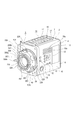
- the imaging apparatus 1 has an apparatus main body 2 and an imaging unit 3, and the imaging unit 3 is detachable from the apparatus main body 2 (see FIGS. 1 to 4).
- the apparatus main body 2 may be provided as an external device with respect to the imaging unit 3, and in this case, the imaging unit 3 is detachable from the external device.
- the imaging unit 3 may be provided as an imaging device alone.
- the apparatus main body 2 has an outer panel 4 and an outer casing 5, and the outer casing 5 is covered with the outer panel 4 (see FIGS. 4 and 5).
- the outer panel 4 has a base panel portion 6, an upper panel portion 7, and a rear panel portion 8.
- the base panel portion 6 is continuous with the bottom surface portion 9 facing the up and down direction and the left and right side edges of the bottom surface portion 9, and is separated from the left and right sides. It has a pair of side surface parts 10 and 11 positioned.
- the base panel unit 6 is provided with various operation units 12, 12,.
- the operation units 12, 12,... For example, a power button, a photographing button, a zoom knob, a mode switching knob, and the like are provided.
- Display portions 13 and 13 such as a liquid crystal panel are arranged on the side surface portions 10 and 11, respectively.
- inflow holes 10a, 10a In the position near the upper end of the side surface portion 10, for example, inflow holes 10a, 10a,.
- outflow holes 11a, 11a,... Extending vertically are formed side by side at a position near the lower end of the side surface portion 11.
- Connection terminals 14, 14,... are arranged one above the other on one side of the rear panel 8 (see FIGS. 1 and 2). Connected to the connection terminals 14, 14,... Are cables (not shown) for supplying power and transmitting / receiving signals.
- the upper panel portion 7 is formed in a plate shape facing the vertical direction, and both left and right end portions are respectively attached to the upper end portions of the side surface portions 10 and 11 (see FIGS. 4 and 5).
- the rear panel portion 8 is formed in a plate shape facing in the front-rear direction, and the outer peripheral portion is attached to the rear end portion of the base panel portion 6 and the rear end portion of the upper panel portion 7.
- the upper panel portion 7 is attached to the side surface portions 10 and 11, and the rear panel portion 8 is attached to the base panel portion 6 and the upper panel portion 7, whereby the outer panel 4 is configured, and the outer casing 5 is the outer panel. 4 from above, below, left, right, and rear (see FIG. 4).
- the adjustment base 15 is attached to the upper surface of the upper panel part 7 (refer FIG. 3 thru
- the adjustment base 15 is formed in a vertically long rectangular shape, a central portion in the left-right direction is formed as a concave groove portion 16, and left and right side portions of the groove portion 16 are provided as adjustment portions 17, 17.
- Slide grooves 17a and 17a that are open on the groove portion 16 side and extend in the front-rear direction are formed in the groove portion 16 side portion of the lower ends of the adjustment portions 17 and 17, respectively.
- the adjusting portions 17 and 17 are formed with adjusting screw holes 17b, 17b,.
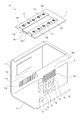
- the outer casing 5 is formed of, for example, a metal material having high thermal conductivity, and includes a main body frame 18 and a side plate 19 (see FIGS. 6 and 7).
- the main body frame 18 includes a top plate 20 that faces in the up-down direction, a bottom plate 21 that faces in the up-down direction that is positioned directly below the top plate 20, an upper edge that is continuous with the outer periphery of the top plate 20, and a lower edge that is the bottom plate 21
- the peripheral surface plate 22 is continuous to the outer peripheral edge, and the frame surface portion 23 is formed in a frame shape.
- the top plate 20 is formed with an insertion hole 20a penetrating vertically.
- the heat sink fins 24, 24,... are connected to the bottom plate 21 in the front and rear direction on the upper surface side.
- the peripheral plate 22 includes a front plate 25 whose upper and lower edges are respectively connected to the front edge of the top plate 20 and the front edge of the bottom plate 21, and both upper and lower edges of the left plate of the top plate 20 and the left side of the bottom plate 21.
- a side plate 26 that is continuous with the edge, and a rear plate 27 that is connected to the rear edge of the top plate 20 and the rear edge of the bottom plate 21, respectively.
- the front plate 25 is formed with fin insertion holes 25a and insertion holes 25b penetrating in the front-rear direction and spaced apart from each other in the vertical direction.
- the side plate 26 is formed with an intake hole 26a and an insertion hole 26b that are penetrated to the left and right, respectively, spaced apart from each other.
- the frame surface portion 23 is continuous with the outer peripheral portion of the front plate 25 and is formed in a substantially rectangular shape.
- An arrangement space 5 a surrounded by the frame surface portion 23 and the front plate 25 is formed in the outer casing 5.
- the side plate 19 is attached to the right end of the main body frame 18 in the left-right direction.
- exhaust holes 19a, 19a,... Penetrating left and right are formed side by side.
- the heat radiating fins 28, 28,... are joined to the left side surface of the side plate 19 side by side.
- the heat radiating fin 28 is provided as a first coupling portion 28a by bending a part of the upper end portion at a right angle, and is provided as a second coupling portion 28b by bending a part of the left end portion at a right angle.
- the radiating fin 28 is provided as a projecting insertion portion 28c in which the left end portion at the upper end portion protrudes leftward with respect to the other portions.
- the first coupling portions 28a, 28a,... are inserted through the insertion holes 20a of the top plate 20, and the second coupling portions 28b, 28b,. 26 insertion holes 26b are inserted.
- a cooling fan 29 is disposed inside the outer casing 5, and the cooling fan 29 is detachable from the outer casing 5 (see FIGS. 6 to 8).
- the cooling fan 29 has a case part 30 penetrating vertically and a blade 31 rotated inside the case part 30, and a space inside the case part 30 is formed as a vent hole 30 a.
- the cooling fan 29 is provided with a connector 32 led out from the case portion 30.
- the cooling fan 29 is configured to cause the air taken in from the upper side to flow downward by the rotation of the blades 31, for example.
- the cooling fan 29 can be taken in and out of the outer casing 5 through an insertion hole 25b formed in the front plate 25 of the outer casing 5, and the entire cooling fan 29 is inserted into the outer casing 5 from the insertion hole 25b. In the state, it is held by a holding unit (not shown) provided inside the outer casing 5.
- the connector 32 is connected to the connector terminal 33 provided in the outer casing 5 so that power can be supplied to the cooling fan 29.
- the connector terminal 33 is connected to one of circuit boards described later.
- the cooling fan 29 is positioned directly below the heat radiating fins 28, 28,... Coupled to the side plate 19 in a state where the cooling fan 29 is disposed inside the outer casing 5.
- the fan cover 34 is attached to the front surface of the front plate 25 by screws or the like, and the cooling fan 29 is covered by the fan cover 34.
- the fan cover 34 is formed in a plate shape that faces in the front-rear direction.
- the cooling fan 29 can be removed from the outer casing 5 by removing the fan cover 34 from the front plate 25 and pulling out the cooling fan 29 from the insertion hole 25b. it can.
- a first circuit board 35 is attached to the outer surface (upper surface) of the top plate 20 in the outer casing 5 (see FIGS. 6 and 9).
- the first coupling portions 28a, 28a,... Of the heat radiation fins 28, 28,... Inserted through the insertion holes 20a are coupled to the lower surface of the first circuit board 35.
- the first circuit board 35 is attached to the upper surface of a first heat transfer plate (not shown) attached to the top plate 20, and the first coupling portions 28a, 28a,. , And the first circuit board 35 may be coupled to the heat radiation fins 28, 28,... Via the first heat transfer plate.
- a second circuit board 36 is attached to the outer surface (rear surface) of the rear plate 27 in the outer casing 5.
- the second circuit board 36 is attached to the rear surface of a second heat transfer plate (not shown) attached to the rear surface of the rear plate 27, and the upper end of the second heat transfer plate and the rear of the first heat transfer plate.
- the second circuit board 36 may be coupled to the radiation fins 28, 28,... Via the second heat transfer plate and the first heat transfer plate.
- a third circuit board 37 is attached above the exhaust holes 19a, 19a, on the outer surface (right side surface) of the side plate 19 in the outer casing 5, a third circuit board 37 is attached above the exhaust holes 19a, 19a,.
- the third circuit board 37 is attached to the right side surface of a third heat transfer plate (not shown) attached to the right side surface of the side plate 19, and the third circuit board 37 is interposed via the third heat transfer plate. It may be coupled to the side plate 19.
- a fourth circuit board 38 is attached to the outer surface (left side surface) of the side plate 26 in the outer casing 5 below the intake holes 26a.
- the second coupling portions 28b, 28b,... Of the heat radiation fins 28, 28,... Inserted through the insertion holes 26b are coupled to the right side surface of the fourth circuit board 38.
- the fourth circuit board 38 is attached to the left side surface of a fourth heat transfer plate (not shown) attached to the side plate 26, and the second coupling portions 28b, 28b, .., And the fourth circuit board 38 may be coupled to the radiation fins 28, 28,... Via the fourth heat transfer plate.
- a first duct portion 98 is disposed between the side surface portion 10 of the outer panel 4 and the side surface plate 26 of the outer casing 5 (see FIG. 9).
- the first duct portion 98 is formed in a cylindrical shape whose left-right direction is an axial direction, and one end surface in the axial direction is joined to a portion around the inflow holes 10a, 10a,. The other end surface in the axial direction is joined to a portion around the intake hole 26 a on the outer surface of the side plate 26.
- a second duct portion 99 is disposed between the side surface portion 11 of the outer panel 4 and the side surface plate 19 of the outer casing 5.
- the second duct portion 99 is formed in a cylindrical shape in which the left-right direction is an axial direction, and one end surface in the axial direction is joined to a portion around the outflow holes 11a, 11a,. The other end surface in the axial direction is joined to a portion around the exhaust holes 19 a, 19 a,.
- the first circuit board 35, the second circuit board 36, the third circuit board 37, and the fourth circuit board 38 are attached to the outer surface of the outer casing 5.
- the circuit board 35, the second circuit board 36, the third circuit board 37, and the fourth circuit board 38 are isolated.
- the first circuit board 35, the second circuit board 36, the third circuit board 37, and the fourth circuit board 36 are not attached to the second circuit board 36, the third circuit board 37, and the fourth circuit board 38. A good operating state of the circuit board 38 can be ensured.
- the first duct portion 98 may be formed integrally with the side surface portion 10 of the outer panel 4 or the side surface plate 26 of the outer housing 5, and the second duct 99 is formed as the side surface portion 11 of the outer panel 4 or the outer housing. 5 side plates 19 may be formed integrally.
- the cooling fan 29 when the cooling fan 29 is rotated, convection is generated as the cooling fan 29 rotates.
- the cooling fan 29 is rotated, as indicated by arrows in FIG. 9, external air is cooled as cooling air from the inflow holes 10 a, 10 a, etc. formed in the side surface portion 10 of the outer panel 4.
- the exhausted air flows into the ventilation plate 30a of the cooling fan 29 from the intake hole 26a formed in the side plate 26 of the outer casing 5, and the exhaust holes 19a and 19a formed in the side plate 19 Are discharged from the outflow holes 11a, 11a,... Formed in the side surface portion 12 of the outer panel 4. Therefore, the cooling air cooling passages are sequentially arranged from the inflow holes 10a, 10a,... Through the intake holes 26a, the vent holes 30a, and the exhaust holes 19a, 19a,. ⁇ It is said to be a flow path.
- the cooling air flows from the cooling holes 29 to the cooling fans 29 along the radiation fins 28, 28,... And exhausts from the cooling fans 29 along the radiation fins 24, 24,. It flows toward the holes 19a, 19a,.
- a battery 500 is mounted on the rear surface of the apparatus body 2 (see FIGS. 1 and 2).
- the battery 500 has a function of supplying power to each part of the apparatus main body 2 and the imaging unit 3.
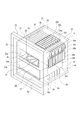
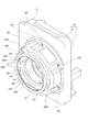
- the imaging unit 3 is configured by arranging necessary parts inside and outside the casing 39 (see FIGS. 10 to 13).
- the housing 39 has a front case portion 40 formed in a thin box shape opened rearward and a rear case portion described later formed in a thin box shape opened forward.
- a transmission hole 40 a penetrating in the front-rear direction is formed at the center of the front case part 40.
- a part of the front surface of the front case portion 40 is formed as a mount portion 41 to which a first accessory and a second accessory described later are selectively attached.
- the portion of the mount 41 that is continuous with the transmission hole 40a is formed as an annular first mount surface 42.
- the mount portion 41 is partially formed as an annular second mount surface 43, and the second mount surface 43 is positioned away from the first mount surface 42 on the outer peripheral side of the first mount surface 42. ing.
- the first mount surface 42 and the second mount surface 43 are located on the same plane and are formed in a concentric shape with the center of the transmission hole 40a as a reference.
- the front case part 40 is provided with positioning pins 42a and 43a protruding forward on the first mount surface 42 and the second mount surface 43, respectively.
- coupling holes 40b and 40b are formed on the outer peripheral side of the first mount surface 42 so as to be spaced apart in the circumferential direction, and the coupling holes 40b and 40b are formed in an arc shape (see FIG. 12). ).
- a screw groove 40c is formed in a portion near the inner periphery of the front case portion 40 (see FIG. 13). Screw holes 40d, 40d,... Opened in the first mount surface 42 are formed in the front case portion 40 so as to be spaced apart in the circumferential direction.
- the inner peripheral surface of the front case part 40 is formed as a positioning part 40e.
- a decorative ring 44 is attached to the front surface of the front case portion 40 between the first mount surface 42 and the second mount surface 43 (see FIGS. 10 to 13).
- a cutout 44a opened downward is formed at the lower end of the decorative ring 44 (see FIG. 12).
- An annular mounting lever 45 is rotatably supported on the front surface of the front case portion 40 between the first mount surface 42 and the decorative ring 44 (see FIGS. 10 to 13).
- the mounting lever 45 includes an annular base portion 45a, coupling portions 45b and 45b projecting rearward from the base portion 45a, and an operation projection 45c projecting forward from the base portion 45a.
- the mounting lever 45 is supported by the front case portion 40 in a state where the coupling portions 45b and 45b are inserted into the coupling holes 40b and 40b, respectively.
- a coupling ring 46 is rotatably supported on the rear surface side of the front case portion 40 (see FIGS. 12 and 13).
- a screwing groove 46 a is formed on the outer peripheral surface of the coupling ring 46, and the screwing groove 46 a is screwed into the screw groove 40 c of the front case part 40.
- Engagement portions 46 b, 46 b, 46 b protruding inward are provided in the inner peripheral portion of the coupling ring 46 so as to be spaced apart in the circumferential direction.
- the coupling ring 46 is coupled with coupling portions 45b and 45b of the mounting lever 45 inserted into the coupling holes 40b and 40b. Accordingly, when the operation protrusion 45c is operated, the mounting lever 45 and the coupling ring 46 are integrally rotated with respect to the front case portion 40, and the screwing groove 46a is screwed into the screw groove 40c along with the rotation. The position is changed, and the mounting lever 45 and the coupling ring 46 are integrally displaced with respect to the front case portion 40 in the front-rear direction.
- contacts 47, 47 are arranged side by side in the circumferential direction on the inner peripheral side of the second mount surface 43.
- the contacts 47, 47 are located in the notch 44 a of the decorative ring 44.
- a filter holder 48 is disposed inside the front case portion 40, and the filter holder 48 is attached to the inner surface of the front case portion 40.
- the filter holder 48 is formed in a shallow case shape opened rearward, and has a through hole 48a penetrating in the front-rear direction.
- the filter holder 48 is provided with a support portion 48b protruding rearward at a portion immediately above the through hole 48a.
- a holding member 49 is attached to the filter holder 48.
- the holding member 49 includes a holding portion 49a formed in a frame shape and a contact arrangement portion 49b protruding downward from the holding portion 49a.
- a substantially rectangular infrared cut filter 50 is held in the holding portion 49a, and contacts 51, 51,... Are arranged in the circumferential direction in the contact arrangement portion 49b.
- the holding member 49 is attached to the filter holder 48 from the front side with the holding portion 49a covering the through hole 48a.
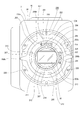
- the intermediate ring 52, the first filter body 53, and the second filter body 54 are disposed on the rear side of the filter holder 48.
- the intermediate ring 52 is positioned between the first filter body 53 and the second filter body 54 in the front-rear direction (optical axis direction), the first filter body 53 is positioned on the front side of the intermediate ring 52, and the second The filter body 54 is positioned on the rear side of the intermediate ring 52 (see FIGS. 12 to 15).
- the intermediate ring 52 includes a substantially annular ring portion 55 and a first drive gear 56, a first driven gear 57, a second drive gear 58, and a second driven gear 59 that are rotatably supported by the ring portion 55, respectively. And have.
- a second driven gear 59, a first drive gear 56, a second drive gear 58, and a first driven gear 57 are sequentially supported on the ring portion 55 in the circumferential direction.
- the first drive gear 56 is a two-stage gear having a small diameter portion 56a and a large diameter portion 56b.
- the small diameter portion 56a is supported on the rear surface side of the ring portion 55, and the large diameter portion 56b is supported on the front surface side of the ring portion 55.
- the second drive gear 58 is a two-stage gear having a small diameter portion 58a and a large diameter portion 58b.
- the small diameter portion 58a is supported on the front side of the ring portion 55, and the large diameter portion 58b is supported on the rear surface side of the ring portion 55.
- a first drive motor 60 and a second drive motor 61 are arranged inside the housing 39, a worm 60 a is provided in the first drive motor 60, and a worm 61 a is provided in the second drive motor 61. It has been.
- the worm 60 a of the first drive motor 60 is meshed with the small diameter portion 56 a of the first drive gear 56. Accordingly, the first drive gear 56 is rotated in a direction corresponding to the rotation direction of the first drive motor 60.
- the worm 61a of the second drive motor 61 is meshed with the small diameter portion 58a of the second drive gear 58 (see FIG. 15). Accordingly, the second drive gear 58 is rotated in a direction corresponding to the rotation direction of the second drive motor 61.
- the first filter body 53 is formed in a substantially disc shape and has a gear portion 53a on the outer peripheral surface (see FIGS. 12 and 14). At the center of the first filter body 53, a supported hole 53b penetrating back and forth is formed.
- a first neutral density filter 62, a second neutral density filter 63, and a transparent plate 64, which are formed in a substantially rectangular shape, are disposed on the first filter body 53, respectively.
- the first neutral density filter 62, the second neutral density filter 63, and the transparent plate 64 are positioned at equal intervals in the circumferential direction.
- the first neutral density filter 62 and the second neutral density filter 63 are also referred to as ND (neutral density) filters, and are neutral density filters that reduce only the amount of light without affecting the color development of the image.
- the first neutral density filter 62 has an optical density lower than the optical density of the second neutral density filter 63, and the first neutral density filter 62 has an optical density of 0.3, for example.
- the neutral density filter 63 has an optical density of 0.6.
- the first filter body 53 has a support portion 48b inserted in the supported hole 53b and is rotatably supported by the filter holder 48 (see FIG. 13).
- the gear portion 53 a is engaged with the large diameter portion 56 b of the first drive gear 56 and the first driven gear 57, and the filter holder 48 is moved in a direction corresponding to the rotation direction of the first drive motor 60. (See FIG. 14).
- any one of the first neutral density filter 62, the second neutral density filter 63, and the transparent plate 64 is positioned immediately behind the infrared cut filter 50, The degree of reduction of the light transmitted through the infrared cut filter 50 is changed according to the rotational position of the filter body 53.
- the second filter body 54 is formed in a substantially disk shape and has a gear portion 54a on the outer peripheral surface (see FIGS. 12 and 15). At the center of the second filter body 54, a supported recessed portion 54b opened forward is formed.
- a third neutral density filter 65, a fourth neutral density filter 66, and a transparent plate 67 which are each formed in a substantially rectangular shape, are disposed.
- the third neutral density filter 65, the fourth neutral density filter 66, and the transparent plate 67 are positioned at equal intervals in the circumferential direction.
- the third neutral density filter 65 and the fourth neutral density filter 66 are also called ND filters, and are neutral density filters that reduce only the amount of light without affecting the color development of the image.
- the third neutral density filter 65 has an optical density lower than that of the fourth neutral density filter 66, and the third neutral density filter 65 has an optical density of 0.9, for example.
- the neutral density filter 66 has an optical density of 1.8. Therefore, the optical density of the third neutral density filter 65 and the fourth neutral density filter 66 is higher than the optical density of the first neutral density filter 62 and the second neutral density filter 63.
- the second filter body 54 has a support portion 48b inserted into the supported recessed portion 54b and is rotatably supported by the filter holder 48 (see FIG. 13).
- the gear portion 54 a is engaged with the large diameter portion 58 b of the second drive gear 58 and the second driven gear 59, and the filter holder 48 is moved in a direction corresponding to the rotation direction of the second drive motor 61. (See FIG. 15).
- any one of the third neutral density filter 65, the fourth neutral density filter 66, and the transparent plate 67 is positioned immediately behind the infrared cut filter 50.
- the neutral density filter 62, the second neutral density filter 63, or the transparent plate 64 is located immediately behind the third neutral density filter 65 and the fourth neutral density filter 65 according to the rotational position of the second filter body 54.
- the degree of reduction of light transmitted through the sex density filter 66 or the transparent plate 67 is changed.
- the third neutral density filter 65 and the fourth neutral density with respect to any of the first neutral density filter 62, the second neutral density filter 63, and the transparent plate 64. Since one of the filter 66 and the transparent plate 67 is positioned on the light incident path (on the optical axis), the first neutral density filter 62, the second neutral density filter 63, the transparent plate 64, and the third Nine kinds of light reduction levels can be set by the combination of the neutral density filter 65, the fourth neutral density filter 66, and the transparent plate 67.
- rotation detection sensors 68 and 68 are arranged on the outer peripheral side of the intermediate ring 52 (see FIG. 12). The rotation positions of the first filter body 53 and the second filter body 54 are detected by the rotation detection sensors 68 and 68.
- the rear cover 69 is attached to the filter holder 48 from behind (see FIGS. 12 and 13).
- the rear cover 69 is formed in a shallow case shape that opens forward, and is attached to the filter holder 48 so as to cover the intermediate ring 52, the first filter body 53, and the second filter body 54 from the rear.
- a substantially rectangular low-pass filter 70 is held at a position near the lower end of the rear cover 69.
- the low-pass filter 70 blocks high-frequency components of light.
- An element holder 71 is disposed behind the rear cover 69.
- the element holder 71 is formed in a substantially rectangular frame shape.
- the element unit 72 is held in the element holder 71.
- the element unit 72 has a plate-like holding base 72a facing substantially in the front-rear direction, an image sensor 72b held by the holding base 72a, an element control board 72c for controlling the image sensor 72b, and a joint attached to both upper and lower ends of the holding base 72a.
- Parts 72d and 72d For example, a CCD (Charge-Coupled Device), a CMOS (Complementary Metal-Oxide-Semiconductor), or the like is used as the imaging element 72b.
- the image sensor 72b is mounted on the front surface of the element control board 72c.
- the element unit 72 is held by the element holder 71 by joining the joints 72d and 72d to the upper and lower ends of the element holder 71, respectively.
- a substrate holder 73 is disposed behind the element holder 71.
- the substrate holder 73 is, for example, formed in a substantially rectangular frame shape with a metal material having high thermal conductivity, and has an arrangement recess 73a that opens forward.
- the substrate holder 73 is formed with an attachment hole 73b communicating with the arrangement recess 73a.
- the substrate holder 73 is attached to the element holder 71, and in a state where the substrate holder 73 is attached to the element holder 71, the imaging element 72b and the element control board 72c are arranged in the arrangement recess 73a.
- a first control board 74 is attached to the upper end of the board holder 73 (see FIG. 13).
- a control circuit that controls driving of the first drive motor 60 and the second drive motor 61 is formed on the first control board 74.
- a second control board 75 is attached to the rear surface of the board holder 73 (see FIGS. 12 and 13).
- the second control board 75 functions as a relay board that performs transmission and reception of signals between the imaging unit 3 and the apparatus body 2 in a state where the imaging unit 3 is attached to the apparatus body 2.
- a heat transfer member 76 is attached to the substrate holder 73 in a state of being inserted into the attachment hole 73b (see FIG. 13). The front end portion of the heat transfer member 76 is joined to the element control board 72c.
- the housing 39 has the front case part 40 and the rear case part 77 as described above (see FIGS. 10, 12, and 13).
- the rear case part 77 is formed in a thin box shape opened forward.
- An insertion hole 77a penetrating in the front-rear direction is formed in the center portion of the rear case portion 77.
- the rear case part 77 is coupled to the rear cover 69 and the filter holder 48 from the rear. In a state where the rear case part 77 is coupled to the rear cover 69 and the filter holder 48, the element holder 71, the element unit 72, the substrate holder 73, the first control board 74, and the second control board 75 are covered by the rear case part 77. Is called.
- the rear end portion of the heat transfer member 76 is inserted into the insertion hole 77a of the rear case portion 77.
- a fin unit 78 is attached to the rear surface of the rear case part 77 (see FIGS. 12 and 13).
- the fin unit 78 has a mounting plate 78a attached to the rear surface of the rear case portion 77 and exhaust heat fins 78b, 78b,... Attached to the rear surface of the attachment plate 78a, and the exhaust heat fins 78b, 78b,. .. are located apart from each other on the left and right.
- the attachment plate 78a is attached to the rear surface of the rear case portion 77 so as to partially cover the insertion hole 77a of the rear case portion 77 from behind, and the rear surface of the heat transfer member 76 is joined to the front surface.
- the heat transfer member 76 has a front end joined to the element control board 72c and a rear end joined to the mounting plate 78a of the fin unit 78. Therefore, the heat generated in the element unit 72 is transmitted to the fin unit 78 via the heat transfer member 76 and is discharged from the heat exhaust fins 78b, 78b,.
- the substrate holder 73 is formed of a metal material having high thermal conductivity and the heat transfer member 76 is attached to the substrate holder 73, the first control board 74 and the second control board 74 respectively attached to the substrate holder 73 are provided. Heat generated in the control board 75 is transmitted to the fin unit 78 through the board holder 73 and the heat transfer member 76 and is discharged from the heat exhaust fins 78b, 78b,.
- the first filter body 53 and the second filter body 54 that reduce the amount of light traveling toward the imaging element 72b are provided and sandwich the second filter body 54 therebetween.
- the first filter body 53 and the image sensor 72b are located, and the first neutral density filter 62 having the lowest optical density is provided in the first filter body 53.
- the first density filter is located closer to the object side than the second filter body 54. Since the first neutral density filter 62 having the lowest optical density is provided in the filter body 53, the first neutral density filter 62 and the second neutral density filter provided in the first filter body 53 are provided. It is difficult for scorch to occur in 63, and deterioration of the first neutral density filter 62 and the second neutral density filter 63 can be suppressed.
- the light is transmitted through the first neutral density filter 62 or the second neutral density filter 63 of the first filter body 53, and the third neutral density filter 65 or the fourth neutral density filter 65 of the second filter body 54. Since the possibility that the light is incident on the neutral density filter 66 of the third neutral density filter 66 increases, the light whose light amount has been reduced by the first neutral density filter 62 or the second neutral density filter 63 becomes the third neutral density filter 65. Alternatively, the light is easily incident on the fourth neutral density filter 66. Therefore, the third neutral density filter 65 and the fourth neutral density filter 66 provided in the second filter body 54 are less likely to be burned, and the third neutral density filter 65 and the fourth neutral density filter 65 are prevented from burning. It is also possible to suppress deterioration of the property density filter 66.
- the infrared cut filter 50 is disposed on the opposite side of the second filter body 54 with the first filter body 53 interposed therebetween, the first neutral density filter 62, the second neutral density filter 63, The light transmitted through the infrared cut filter 50 is incident on the third neutral density filter 65 and the fourth neutral density filter 66.
- the first neutral density is suppressed by suppressing the temperature rise of the first neutral density filter 62, the second neutral density filter 63, the third neutral density filter 65, and the fourth neutral density filter 66.
- Good performance of the filter 62, the second neutral density filter 63, the third neutral density filter 65, and the fourth neutral density filter 66 can be ensured.
- first filter body 53 and the second filter body 54 are respectively rotatable, and the first filter body 53 and the second filter body 54 have optical densities different from each other and are spaced apart in the circumferential direction.
- a first neutral density filter 62, a second neutral density filter 63, a third neutral density filter 65, and a fourth neutral density filter 66 are provided.
- the imaging unit 3 configured as described above is detachable from the outer casing 5 of the apparatus main body 2 as described above (see FIGS. 3 and 4).
- the imaging unit 3 is attached to the outer casing 5 in an arrangement space 5a in which at least a part of the imaging unit 3 is formed at the front end of the outer casing 5 in a state where the cooling fan 29 is arranged inside the outer casing 5.
- the imaging unit 3 is fixed to the front plate 25 or the frame surface portion 23 by screws or the like.
- the heat exhaust fins 78 b, 78 b,... Of the fin unit 78 are inserted from the fin insertion holes 25 a of the front plate 25 and are positioned inside the outer casing 5. (See FIG. 9).
- the exhaust heat fins 78b, 78b,... Pass through the intake holes 26a, the vent holes 30a, and the exhaust holes 19a, 19a,. It is located in the cooling flow path of the cooling air.
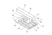
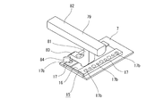
- a handle 79 is detachably attached to the adjustment base 15 attached to the upper surface of the upper panel portion 7 in the outer panel 4 (see FIGS. 16 to 18).
- the handle 79 has a base pedestal portion 80 extending in the front-rear direction, a connecting portion 81 projecting upward from one end portion in the longitudinal direction of the base pedestal portion 80, and an upper end portion of the connecting portion 81 extending in the same direction as the base pedestal portion 80 And a hand portion 82.
- a supported plate 83 is detachably attached to the lower surface of the base table 80. Both left and right end portions of the supported plate 83 are provided as guided portions 83a and 83a protruding in opposite directions.
- a lock lever 84 is supported on the base table 80.
- the handle 79 has a guided portion 83a, 83a of the supported plate 83 inserted in the slide groove 17a, 17a of the adjustment base 15 and slid on the adjustment portion 17, 17, respectively. It is possible to slide to. Therefore, the handle 79 can be attached to the adjustment table 15 at a desired position by moving the handle 79 in the front-rear direction with respect to the adjustment table 15. In a state where the handle 79 is moved in the front-rear direction with respect to the adjustment table 15, the handle 79 is locked at the position moved with respect to the adjustment table 15 by operating the lock lever 84.
- the handle 79 is movable in the front-rear direction with respect to the adjustment table 15, and therefore, when the image pickup apparatus 1 is used, the center of gravity of the entire handle is taken into consideration and the handle 79 is held in the most balanced position.
- a handle 79 can be attached to perform stable shooting.
- the handle 79 can be reversed and the guided portions 83a and 83a can be inserted into the slide grooves 17a and 17a and slid on the adjusting portions 17 and 17 (see FIG. 19). Therefore, by setting the handle 79 in an easy-to-hold direction, a good shooting state can be ensured.
- the handle 79 can be attached to the adjustment base 15 with the base base portion 80 and the handle portion 82 extending in the left-right direction (see FIG. 20).
- the supported plate 83 is removed from the base pedestal 80, and a mounting screw (not shown) is screwed into the desired adjustment screw hole 17 b to attach the base pedestal 80 to the one adjustment portion 17.
- the handle 79 can be attached to the adjustment base 15 in such a direction that the handle portion 82 extends in the left-right direction in this way, the degree of freedom of the orientation of the handle 79 relative to the adjustment base 15 is increased, and the handle 79 can be easily gripped. By setting the direction, it is possible to ensure a better shooting state.
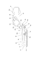
- the finder unit 85 is also detachable from the adjustment base 15 (see FIGS. 16 and 21).
- the viewfinder unit 85 includes shaft holders 86 and 87, guided members 88, support shafts 89 and 89, a rotating arm 90, and a view main body 91.
- the shaft holder 86 is connected to the left and right and has cylindrical support tube portions 86a and 86a, respectively.
- a first lock lever 92 is supported on the shaft holder 86.
- the shaft holder 87 is connected to the left and right and has cylindrical support cylinders 87a and 87a and cylindrical connection cylinders 87b and 87b positioned above the support cylinders 87a and 87a, respectively.
- the axial directions of the connecting cylinder portions 87b and 87b are orthogonal to the axial direction of the support cylinder portions 87a and 87a.
- a second lock lever 93 is supported on the lower side of the shaft holder 87, and a third lock lever 94 is supported on the upper side.
- the guided member 88 is connected to the lower side of the shaft holder 86.
- the left and right end portions of the guided member 88 are provided as guided portions 88a and 88a protruding in opposite directions.
- a fourth lock lever 95 is supported on the guided member 88.
- the support shafts 89 and 89 are inserted into the shaft holders 86 and 87 in a state parallel to the left and right.
- the support shaft 89 is inserted into the support tube portion 86 a of the shaft holder 86 and the support tube portion 87 a of the shaft holder 87, and is slidable in the axial direction (front-rear direction) with respect to the shaft holders 86 and 87.
- the rotation arm 90 includes a rotation fulcrum portion 90a that is connected to the view main body 91 so as to be capable of being connected, an arm portion 90b that protrudes from the rotation fulcrum portion 90a, and a connection shaft portion 90c that protrudes from the arm portion 90b.
- the connecting shaft 90c has a protruding direction from the arm 90b orthogonal to the protruding direction of the arm 90b from the rotation fulcrum 90a.
- a fifth lock lever 96 is supported on the rotation fulcrum 90 a of the rotation arm 90.
- Rotating arm 90 has a connecting shaft portion 90c inserted into connecting tube portions 87b and 87b of shaft holder 87, and connecting shaft portion 90c is slidable in the axial direction (left-right direction) with respect to shaft holder 87.
- the connecting shaft portion 90 c is locked to the shaft holder 87 by operating the third lock lever 94.
- the connecting shaft portion 90c can be rotated in the direction around the shaft by the shaft holder 87, and when the connecting shaft portion 90c is rotated with respect to the shaft holder 87, the third lock lever 94 is operated.
- the connecting shaft portion 90 c is locked to the shaft holder 87.
- the rotation arm 90 has a rotation fulcrum portion 90a connected to the view main body 91 so as to be rotatable with respect to each other, and operates the fifth lock lever 96 in a state where the rotation arm 90 or the view main body 91 is rotated. As a result, the view body 91 is locked.
- the view main body 91 is provided with one end portion as a finder portion 91a and a connecting fulcrum portion 91b connected to the rotation fulcrum portion 90a at the other end portion.
- the finder unit 85 is moved back and forth with respect to the adjustment table 15 by the guided portions 88a and 88a of the guided member 88 being inserted into the slide grooves 17a and 17a of the adjustment table 15 and sliding on the adjustment units 17 and 17, respectively. It is slidable in the direction. Therefore, the finder unit 85 can be attached to a desired position with respect to the adjustment table 15 by moving the finder unit 85 in the front-rear direction with respect to the adjustment table 15. In a state where the finder unit 85 is moved in the front-rear direction with respect to the adjustment table 15, the finder unit 85 is locked at a position moved with respect to the adjustment table 15 by operating the fourth lock lever 95.
- the finder unit 85 is movable in the front-rear direction with respect to the adjustment table 15, the finder unit 85 is attached to a position with the best balance in consideration of the entire center of gravity when the imaging apparatus 1 is used. Stable shooting can be performed.
- the finder unit 85 can be slid on the adjusting portions 17 and 17 by inserting the guided portions 88a and 88a into the slide grooves 17a and 17a in the opposite direction. Therefore, by setting the finder unit 85 in an easy-to-see direction, a good shooting state can be ensured.
- the support shafts 89 and 89 can be moved with respect to the shaft holders 86 and 87.
- a better shooting state can be achieved. Can be secured.
- the finder unit 85 can rotate the connecting shaft portion 90c in the direction around the axis with respect to the shaft holder 87, and the rotation fulcrum portion 90a is connected to the view body 91 so as to be rotatable relative to each other.
- the viewfinder 91a of the view main body 91 can be adjusted and used in a desired direction, and an even better shooting state can be secured (see FIGS. 22 and 23).
- finder unit 85 can move the connecting shaft portion 90c in the left-right direction with respect to the shaft holder 87 (see FIGS. 24 and 25).
- the finder portion 91a of the view main body 91 can be used by adjusting it to a desired position in the left-right direction, and a better shooting state can be ensured.
- the guided member 88 is attached to one adjusting portion 17 by screwing a mounting screw (not shown) into a desired adjusting screw hole 17b with the support shafts 89, 89 extending in the left-right direction. May be enabled.
- the finder unit 85 may be configured such that the connecting shaft portion 90 c of the rotating arm 90 is inserted into the shaft holders 86 and 87 instead of the support shaft 89.
- the viewfinder 91a of the view main body 91 can be set to be viewed from the left-right direction, and the degree of freedom of the shooting mode is increased. It is possible to secure a better shooting state.
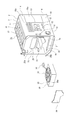
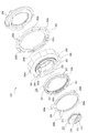
- the first accessory 100 and the second accessory 200 are selectively attached to the mount portion 41 of the imaging unit 3. It should be noted that accessories other than the first accessory 100 and the second accessory 200 may be detachable from the mount portion 41.
- the first accessory 100 is, for example, an interchangeable lens, and required parts are arranged inside and outside the outer cylinder 101 (see FIG. 1).
- the first accessory 100 is attached to the imaging unit 3 with a part thereof in contact with the first mount surface 42 of the mount portion 41.
- a plurality of lens groups are arranged in the outer cylinder 101 so as to be separated in the optical axis direction.
- a portion near the rear end of the outer cylinder 101 is provided as a mounting portion 102, and an outer peripheral portion of the rear surface of the mounting portion 102 is formed as a mounting surface 102a.
- the mounting portion 102 is formed with a positioning hole (not shown) opened in the mounting surface 102a.
- the rear end portion of the outer cylinder 101 is provided as a coupling portion 103.
- the coupling portion 103 protrudes rearward from a portion inside the mounting surface 102a of the mounting portion 102 and is formed in a substantially cylindrical shape.
- Arc-shaped engagement pieces 104, 104, 104 protruding outward are provided at the rear end portion of the coupling portion 103 so as to be spaced apart in the circumferential direction.
- a plurality of terminals (not shown) arranged side by side in the circumferential direction are arranged in the coupling portion 103.
- the diameter of the outer peripheral surface 103a in the coupling portion 103 is substantially the same as the inner diameter of the front case portion 40, that is, the diameter of the positioning portion 40e.
- the first accessory 100 is attached to the mount 41 of the imaging unit 3 as follows.
- the positioning pin 42a of the mounting portion 41 is inserted into the positioning hole formed in the mounting portion 102, and the mounting surface 102a of the mounting portion 102 is in proximity to or in contact with the first mounting surface 42.
- the coupling portion 103 is inserted into the transmission hole 40a.
- the engagement pieces 104, 104, 104 of the coupling portion 103 are respectively inserted into the portions between the engagement portions 46 b, 46 b, 46 b of the coupling ring 46, and the engagement pieces 104, 104, 104 are in front of the filter holder 48.
- the terminal of the coupling part 103 is connected to the contacts 51, 51,.
- the diameter of the outer peripheral surface 103a in the coupling portion 103 is substantially the same as the diameter of the positioning portion 40e. Therefore, when the coupling portion 103 is inserted into the transmission hole 40a, the positioning portion 40e causes the first Positioning in the direction orthogonal to the optical axis direction of the accessory 100 is performed.
- the mounting lever 45 is rotated, and the coupling ring 46 is rotated with respect to the front case portion 40 together with the mounting lever 45.
- the coupling ring 46 is rotated, the screwing position of the screwing groove 46a with respect to the screw groove 40c is changed with the rotation of the coupling ring 46, and the mounting lever 45 and the coupling ring 46 are integrated into the front case portion 40.
- it is displaced backward.
- the coupling ring 46 is rotated, the engaging portions 46b, 46b, 46b are positioned in front of the engaging pieces 104, 104, 104, respectively, and the engaging portions 46b, 46b, 46b are respectively engaged with the engaging pieces 104, 104. , 104.
- the first accessory 100 is attached to the mount portion 41 with the surface 102 a in contact with the first mount surface 42.
- the second accessory 200 is an adapter, for example, and has a substantially annular support base 201 (see FIGS. 2, 13, 26, 27, and 28).
- the support base 201 is formed with an annular recess 201a that is opened rearward.
- the annular recess 201a is formed in an annular shape.
- An annular projecting portion 201 b that protrudes rearward is provided on the inner peripheral portion of the support base 201.
- the annular protrusion 201b is formed in a stepped shape with a cross-sectional shape, and is formed in a shape that decreases in diameter toward the rear.
- the outer diameter of a part of the annular protrusion 201b is substantially the same as the inner diameter of the front case portion 40, that is, the diameter of the positioning portion 40e.
- a substantially annular mounting ring 202 is attached to the outer peripheral portion of the rear surface of the support base 201.
- the rear surface of the mounting ring 202 is formed as a mounting surface 202a.
- the mounting surface 202a is positioned in front of the rear surface of the annular protrusion 201b.
- the mounting ring 202 has a positioning hole (not shown) opened in the mounting surface 202a. In the mounting ring 202, screw insertion holes 202b, 202b,.
- a receiving ring 203 is attached to the inner periphery of the front end of the support base 201.
- a screw groove 203 a is formed on the outer peripheral surface of the receiving ring 203.
- the receiving ring 203 is formed with notches 203b and 203b that are opened forward and inward and spaced apart in the circumferential direction.
- Contact points 204, 204,... are arranged in the circumferential direction on the front surface of the support base 201.
- the contacts 204, 204,... are located in the notches 203b, 203b of the receiving ring 203.
- a mounting ring 205 is rotatably supported by the receiving ring 203.
- the attachment ring 205 has a substantially annular annular portion 206 and engaging portions 207, 207,... Projecting inward from the front end portion of the annular portion 206, and the engaging portions 207, 207,. -Are provided in the circumferential direction apart.
- a screwing groove 206 a is formed on the inner peripheral surface of the annular portion 206, and the screwing groove 206 a is screwed into the screw groove 203 a of the receiving ring 203.
- An annular operation lever 208 is attached to the front end of the attachment ring 205.
- the operation lever 208 has an annular base portion 208a and operation protrusions 208b, 208b, 208b protruding from the base portion 208a.
- the operation protrusions 208b, 208b, and 208b are spaced apart in the circumferential direction.
- a terminal arrangement member 209 is attached to the rear surface of the support base 201.
- the terminal arrangement member 209 is formed in a shape along the annular recess 201a of the support base 201, and has an annular relief recess 209a. .. Are arranged side by side in the circumferential direction on the rear surface of the lower end portion of the terminal arrangement member 209.
- a window member 211 is attached to the inner peripheral surface of the annular protrusion 201b of the support base 201 by, for example, screwing or the like.
- the window member 211 has a substantially annular flange base 212 and connecting surface portions 213, 213,... That protrude from the rear end portion of the flange base 212 toward each other, and inner ends of the connecting surface portions 213, 213,. It has the protruding protrusions 214, 214,... Protruding rearward from the edges.
- the connecting surface portions 213, 213,... are formed, for example, in a straight line in which four ends are provided in the front-rear and left-right directions and the inner edge extends in the left-right direction or the up-down direction.
- a so-called flocking coating is formed on the inner surface of the window member 211 to form a texture in which a small number of flocks exist.
- the operation protrusion 208b when the operation protrusion 208b is operated, the operation lever 208 and the mounting ring 205 are integrally rotated with respect to the receiving ring 203, and the screw groove of the screw groove 206a is rotated with the rotation.
- the screwing position with respect to 203a is changed, and the operation lever 208 and the mounting ring 205 are integrally displaced with respect to the receiving ring 203 in the front-rear direction.
- the second accessory 200 is attached to the mount portion 41 of the apparatus main body 2 as follows.
- the positioning pin 43a of the mount unit 41 is inserted into the positioning hole formed in the mounting unit 202, and the mounting surface 202a of the mounting unit 202 is pressed against the second mount surface 43 from the front side.
- the annular protrusion 201b of the support base 201 and the portion excluding the front end of the window member 211 are inserted into the transmission hole 40a (see FIG. 13).
- the terminals 210, 210,... Arranged on the terminal arrangement member 209 are connected to the contacts 47, 47,.
- the operation projection 45 c of the mounting lever 45 is inserted into the relief recess 209 a of the terminal arrangement member 209.
- the terminal arrangement member 209 is formed with the relief recess 209a into which the operation protrusion 45c of the mounting lever 45 is inserted, the mounting lever 45 is attached to the mounting portion 41 when the second accessory 200 is attached to the second mounting portion 45.
- the second accessory 200 can be smoothly attached to the mount portion 41 without interfering with the accessory 200.
- the outer diameter of a part of the annular protrusion 201b is substantially the same as the diameter of the positioning portion 40e. Therefore, when the annular protrusion 201b is inserted into the transmission hole 40a, the outer diameter is increased by the positioning portion 40e. The positioning of the second accessory 200 in the direction orthogonal to the optical axis direction is performed.
- screws 220, 220,... are inserted into the screw insertion holes 202b, 202b,..., Respectively, and the screws 220, 220,.
- the second accessory 200 is attached to the mount portion 41 in a state where the mounting surface 202 a is in contact with the second mount surface 43.
- the contacts 51, 51,... To which the terminals of the first accessory 100 are connected are shielded by the window member 211.
- the contacts 51, 51,... are shielded, so that reflection of light at the contacts 51, 51,.
- the quality of the captured image can be improved.
- the opening edge of the holding portion 49a in the holding member 49 is shielded by the protruding protrusions 214, 214,.
- the opening edge of the holding portion 49a is shielded when the first accessory 100 is not used, it is possible to prevent further reflection of light at the holding portion 49a when the second accessory 200 is used and to further improve the image taken. The quality can be improved.
- the inner surface of the window member 211 is flocked, the reflection of light at the window member 211 is prevented when the second accessory 200 is used, and the quality of the captured image is further improved. be able to.
- the imaging unit 3 is formed with a positioning portion 40e for positioning the first accessory 100 and the second accessory 200 in the direction orthogonal to the optical axis.
- the positioning in the direction orthogonal to the optical axis of the first accessory 100 and the second accessory 200 with respect to the housing 39 of the imaging unit 3 is performed by one positioning unit 40e, the first accessory 100 The same positioning accuracy with respect to the housing 39 is ensured when the second accessory 200 is mounted on the mount surface 42 and when the second accessory 200 is mounted on the second mount surface 43, and the second accessory 200 is mounted when the first accessory 100 is mounted. It is possible to improve the quality of images taken when the camera is mounted.
- the third accessory 300 is attached to the second accessory 200 (see FIG. 2).
- the third accessory 300 is, for example, an interchangeable lens, and each required part is arranged inside and outside the outer cylinder 301.
- a plurality of lens groups are arranged apart from each other in the optical axis direction.
- the rear end portion of the outer cylinder 301 is provided as a coupling portion 302.
- Arc-shaped engagement pieces 303, 303,... Projecting outward are provided at the rear end of the coupling portion 302 so as to be spaced apart in the circumferential direction.
- the coupling portion 302 is provided with a plurality of terminals (not shown) that are spaced apart in the circumferential direction.
- a photographing frame 304 is detachably attached to the front end portion of the outer cylinder 301.
- the third accessory 300 is attached to the second accessory 200 as follows.
- the third accessory 300 is brought into a state in which the rear surface of the coupling portion 302 is in proximity to or in contact with the receiving ring 203 from the front side, and the coupling portion 302 is inserted inside the attachment ring 205.
- the engaging pieces 303, 303,... Of the coupling portion 302 are inserted into the portions between the engaging portions 207, 207,. Is brought close to or in contact with the front surface of the receiving ring 203.
- bond part 302 is connected to the contact 204,204, ....
- the operation lever 208 is rotated and the mounting ring 205 is rotated with respect to the receiving ring 203 together with the operation lever 208.
- the mounting ring 205 is rotated, the screwing position of the screwing groove 206 a with respect to the screw groove 203 a is changed with the rotation of the mounting ring 205, and the operation lever 208 and the mounting ring 205 are integrated with the receiving ring 203. Is displaced backwards.
- the engaging portions 207, 207,... are positioned on the front side of the engaging pieces 303, 303,. It is pressed against the engagement pieces 303, 303,.
- the engaging portions 207, 207,... are pressed against the engaging pieces 303, 303,.
- the third accessory 300 is attached to the second accessory 200 by being sandwiched by the receiving ring 203.
- the housing 39 having the mount portion 41 to which at least the first accessory 100 and the second accessory 200 are selectively attached, and the captured light as an electrical signal.
- the first mount surface 42 and the second mount surface 43 are located on the same plane.
- first accessory 100 and the second accessory 200 are attached to the first mount surface 42 and the second mount surface 43, respectively, located on the same plane. Regardless of which of the second accessories 200 is attached, it is possible to ensure good optical performance and improve image quality.
- the mount portion 41 Even when either the first accessory 100 or the second accessory 200 is attached to the mount portion 41, the high accuracy of the length of the flange back is ensured, and the image quality is ensured by ensuring good optical performance. Improvements can be made.
- both the first mount surface 42 and the second mount surface 43 are formed as a part of the front case portion 40, the first mount surface 42 and the second mount surface 43 are the same member.
- high planar accuracy of the first mount surface 42 and the second mount surface 43 can be secured, and the number of components can be reduced and the strength can be improved.
- the cooling air flows from the cooling holes 29 to the cooling fans 29 along the radiation fins 28, 28,... And exhausts from the cooling fans 29 along the radiation fins 24, 24,. It flows toward the holes 19a, 19a,.
- the heat generated in the first circuit board 35 is mainly transmitted from the first coupling portions 28a, 28a, ... to the radiation fins 28, 28, ....
- the heat generated in the second circuit board 36 is mainly transmitted from the rear plate 27 to the heat radiation fins 28, 28,... Via the side plate 19 and radiated from the rear plate 27 via the bottom plate 21. It is transmitted to the fins 24, 24,.
- the heat generated in the third circuit board 37 is mainly transmitted to the radiation fins 28, 28,.
- the heat generated in the fourth circuit board 38 is mainly transmitted from the second coupling portions 28b, 28b,... To the radiation fins 28, 28,.
- the heat generated in the first circuit board 35, the second circuit board 36, the third circuit board 37, and the fourth circuit board 38 are all radiating fins 28, 28,. , 24,... Therefore, the air flows from the intake hole 26a along the heat radiation fins 28, 28,... Toward the cooling fan 29, and from the cooling fan 29 along the heat radiation fins 24, 24,. Heat is efficiently released from the radiation fins 28, 28,... Or the radiation fins 24, 24,.
- the temperature rise of the second circuit board 36, the third circuit board 37, and the fourth circuit board 38 is suppressed.
- the heat generated in the first control board 74, the second control board 75, and the element control board 72c of the image pickup unit 3 is mainly exhausted through the board holder 73, the heat transfer member 76, and the mounting plate 78a. It is transmitted to the fins 78b, 78b,.
- the outer casing 5 in which the insertion hole 25b into which the cooling fan 29 is inserted is formed and the imaging element 72b are detachable from the outer casing 5 and are detachable.
- the cooling fan 29 can be pulled out from the insertion hole 25 b and removed from the outer casing 5, so that the maintainability of the cooling fan 29 is improved and the imaging apparatus 1 is improved. It is possible to ensure a good operating state.
- the outer casing 5 has a top plate 20 that faces in the vertical direction and a peripheral plate 22 whose upper edge is continuous with at least a part of the outer periphery of the top plate 20, and an insertion hole 25 b is formed in the peripheral plate 22. Yes.
- the outer casing 5 is provided with a pair of side plates 19 and 26 facing each other, and the side plates 26 are formed with intake holes 26a for taking in external air as cooling air, and the side plates 19 are provided with the outer casing 5 from the intake holes 26a.
- Exhaust holes 19a, 19a,... Are formed for discharging the cooling air taken into the outside to the outside.
- the cooling flow path is formed between the side plate 19 and the side plate 26, the cooling air is smoothly flowed inside the outer casing 5, and each part or the outer casing 5 disposed inside the outer casing 5. It is possible to improve the cooling efficiency for each part to be attached.
- a cooling flow path for cooling air is formed by rotation of the cooling fan 29 from the intake hole 26a through the cooling fan 29 to the exhaust holes 19a, 19a,...
- the heat generated in the first circuit board 35, the second circuit board 36, the third circuit board 37, and the fourth circuit board 38 is transmitted from the outer casing 5 to the radiation fins, and the radiation fins 24, 24,. .., 28, 28,... Are discharged into the cooling flow path, so that it is possible to further improve the cooling efficiency for each part disposed inside the outer casing 5 and each part attached to the outer casing 5. .
- the outer casing 5 is made of a material having thermal conductivity, and the first circuit board 35, the second circuit board 36, the third circuit board 37, and the fourth circuit board 38 are attached to the outer casing 5.
- the cooling fan 29 is disposed at a position surrounded by the first circuit board 35, the second circuit board 36, the third circuit board 37, and the fourth circuit board 38.
- the cooling fan 29 is located inside the first circuit board 35, the second circuit board 36, the third circuit board 37, and the fourth circuit board 38, the cooling flow path for the cooling air is the first.
- the first circuit board 35, the second circuit board 36, the third circuit board 37, and the fourth circuit board 38 are formed inside the first circuit board 35, the second circuit board 36, and the third circuit board 38.
- the cooling efficiency for the substrate 37 and the fourth circuit substrate 38 can be improved.
- the cooling fan 29 is located inside the first circuit board 35, the second circuit board 36, the third circuit board 37, and the fourth circuit board 38, the space inside the outer casing 5 is Can be effectively utilized as a space for disposing the cooling fan 29, and the imaging apparatus 1 can be downsized while improving the cooling efficiency.
- a first control board 74, a second control board 75, and an element control board 72c are arranged inside the imaging unit 3, and the first control board 74, the second control board 75, and element control are arranged in the imaging unit 3.
- Exhaust heat fins 78b, 78b,... That release heat generated in the substrate 72c are provided, and the outer casing 5 is formed with fin insertion holes 25a through which the exhaust heat fins 78b, 78b,. In the state where the imaging unit 3 is attached to the outer casing 5, the heat exhaust fins 78b, 78b,... Are positioned in the cooling flow path.
- the rise in the temperature of the first control board 74, the second control board 75, and the element control board 72c is suppressed by the cooling air taken in from the intake hole 26a in a state where the imaging unit 3 is attached to the outer casing 5. Therefore, a dedicated cooling means for suppressing the temperature rise of the first control board 74, the second control board 75, and the element control board 72c is not required, and the first structure is simplified after the structure is simplified. The cooling efficiency of the control board 74, the second control board 75, and the element control board 72c can be improved.
- the outer casing 5 is provided with a frame surface portion 23 in which the inner space is formed as the arrangement space 5a, and at least a part of the imaging unit 3 is attached to the outer casing 5 in a state of being inserted into the arrangement space 5a.
- the imaging unit 3 is attached to the outer casing 5 in a state where at least a part of the imaging unit 3 is inserted into the arrangement space 5a, the imaging unit 3 can be easily attached to the outer casing 5. In addition, a stable attachment state of the imaging unit 3 to the outer casing 5 can be ensured.
- An imaging device (video camera) 1 includes an imaging element 72b having a photoelectric conversion function for converting captured light into an electrical signal, and a camera signal processing unit 401 that performs signal processing such as analog-digital conversion of a captured image signal. And an image processing unit 402 that performs recording / reproduction processing of an image signal.
- the imaging apparatus 1 includes a display unit 403 (display unit 13) that displays captured images and the like, an R / W (reader / writer) 404 that writes and reads image signals to and from the memory 408, and imaging.
- a CPU (Central Processing Unit) 405 that controls the entire apparatus 1, an input unit 406 (operation unit 12) such as various switches that are operated by a user, and the first accessory 100 or the third accessory 300.
- a lens drive control unit 407 for controlling the driving of the lens provided in the lens.
- the camera signal processing unit 401 performs various signal processing such as conversion of an output signal from the image sensor 72b into a digital signal, noise removal, image quality correction, and conversion into a luminance / color difference signal.
- the image processing unit 402 performs compression encoding / decompression decoding processing of image signals based on a predetermined image data format, conversion processing of data specifications such as resolution, and the like.
- the display unit 403 has a function of displaying various data such as an operation state of the user input unit 406 and a captured image.
- the R / W 404 writes the image data encoded by the image processing unit 402 to the memory 408 and reads the image data recorded in the memory 408.
- the CPU 405 functions as a control processing unit that controls each circuit block provided in the imaging apparatus 1, and controls each circuit block based on an instruction input signal from the input unit 406.
- the input unit 406 outputs an instruction input signal corresponding to the operation by the user to the CPU 405.
- the lens drive control unit 407 controls a motor (not shown) that drives the lens groups 410, 410,... Based on a control signal from the CPU 405.
- the memory 408 is a semiconductor memory that can be attached to and detached from a slot connected to the R / W 404, for example. Note that the memory 408 may not be detachable from the slot but may be incorporated in the imaging apparatus 1.
- the captured image signal is output to the display unit 403 via the camera signal processing unit 401 under the control of the CPU 405 and displayed as a camera-through image.
- the CPU 405 outputs a control signal to the lens drive control unit 407, and a predetermined lens group 410 is set based on the control of the lens drive control unit 407. Moved.
- the shot image signal is output from the camera signal processing unit 401 to the image processing unit 402, subjected to compression coding processing, and converted into digital data of a predetermined data format. Is done.
- the converted data is output to the R / W 404 and written to the memory 408.
- Focusing is performed by the lens drive control unit 407 moving a predetermined lens group 410 based on a control signal from the CPU 405.
- predetermined image data is read from the memory 408 by the R / W 404 in accordance with an operation on the input unit 406, and decompression decoding processing is performed by the image processing unit 402. After that, the reproduced image signal is output to the display unit 403 to display the reproduced image.
- imaging refers to conversion from a photoelectric conversion process in which light captured by the image sensor 72 b is converted into an electrical signal to a digital signal for an output signal from the image sensor 72 b by the camera signal processing unit 401.
- Processing such as noise removal, image quality correction, conversion to luminance / color difference signals, compression / decompression processing of image signals based on a predetermined image data format by the image processing unit 402, and conversion processing of data specifications such as resolution ,
- imaging may refer only to a photoelectric conversion process that converts light captured by the image sensor 72 b into an electrical signal, and from a photoelectric conversion process that converts light captured by the image sensor 72 b into an electrical signal.
- the camera signal processing unit 401 may refer to processing such as conversion of an output signal from the image sensor 72b into a digital signal, noise removal, image quality correction, and conversion to a luminance / color difference signal, and the like.
- the camera signal processing unit 401 converts the output signal from the image sensor 72b to a digital signal, noise removal, image quality correction, conversion to a luminance / color difference signal, and the like, Data such as compression encoding / decompression decoding processing and resolution of an image signal based on a predetermined image data format by the image processing unit 402 It may refer to the conversion process of the specification.
- the imaging unit and the imaging device are configured to include only a part or all of the imaging element 72b, the camera signal processing unit 401, the image processing unit 402, and the R / W 404 that perform the above processing. Also good.
- the imaging unit may include a part of the imaging element 72b, the camera signal processing unit 401, the image processing unit 402, and the R / W 404, and the apparatus main body 2 may be configured to include the rest.
- the present technology can be configured as follows.
- a housing having a mount portion to which at least the first accessory and the second accessory are selectively attached; An image sensor that photoelectrically converts the captured light into an electrical signal;
- the mount portion is formed with a first mount surface to which the first accessory is attached and a second mount surface to which the second accessory is attached, An imaging apparatus in which the first mount surface and the second mount surface are positioned on the same plane.
- a contact is provided to which the terminal of the first accessory is connected in a state where the first accessory is attached to the first mount surface;
- the first filter body and the imaging element are located on the opposite side across the second filter body,
- the imaging device according to any one of (1) to (4), wherein the first filter body is provided with a neutral density filter having the lowest optical density among the neutral density filters.
- Each of the first filter body and the second filter body is rotatable, The optical filter according to (5) or (6), wherein the first filter body and the second filter body are each provided with a plurality of neutral density filters that have different optical densities and are spaced apart in the circumferential direction. Imaging device.
- a housing having a mount portion to which at least the first accessory and the second accessory are selectively attached; An image sensor that photoelectrically converts light taken in and disposed inside the housing into an electrical signal;
- the mount portion is formed with a first mount surface to which the first accessory is attached and a second mount surface to which the second accessory is attached, An imaging unit in which the first mount surface and the second mount surface are positioned on the same plane.
- An image sensor that photoelectrically converts the captured light into an electrical signal;
- a first filter body having at least one neutral density filter that is positioned on the optical axis and reduces the amount of light directed to the image sensor;
- a second filter body having at least one neutral density filter positioned on the optical axis and spaced apart from the first filter body to reduce the amount of light directed to the imaging device;
- the first filter body and the imaging element are located on the opposite side across the second filter body, An imaging apparatus, wherein the neutral density filter having the lowest optical density among the neutral density filters is provided on the first filter body.
- Each of the first filter body and the second filter body is rotatable, The optical filter according to (9) or (10), wherein the first filter body and the second filter body are each provided with a plurality of the neutral density filters that have different optical densities and are spaced apart in the circumferential direction. Imaging device.
- a housing having a mount portion to which accessories are attached; An image sensor that photoelectrically converts light taken in and disposed inside the housing into an electrical signal; A first filter body having at least one neutral density filter that is positioned on the optical axis and reduces the amount of light directed to the image sensor; A second filter body having at least one neutral density filter positioned on the optical axis and spaced apart from the first filter body to reduce the amount of light directed to the imaging device; The first filter body and the imaging element are located on the opposite side across the second filter body, An image pickup unit in which the first filter body is provided with a neutral density filter having the lowest optical density among the neutral density filters.
Abstract
The purpose of the present invention is to increase the quality of an image while ensuring suitable optical performance. Provided is an imaging device that includes a housing having a mount portion whereon at least a first accessory and a second accessory are selectively mounted and an imaging element for photoelectrically converting captured light into an electric signal, wherein the mount portion has a first mount surface whereon the first accessory is mounted and a second mount surface whereon the second accessory is mounted, and the first mount surface and the second mount surface are located on the same plane. This allows the first accessory and the second accessory to be selectively mounted on the first mount surface and the second mount surface located on the same plane respectively, thereby increasing the quality of an image while ensuring suitable optical performance.
Description
本技術はアクセサリーがマウント部に対して着脱可能にされた撮像装置及び撮像ユニットについての技術分野に関する。
This technology relates to the technical field of an imaging device and an imaging unit in which accessories can be attached to and detached from the mount portion.
ビデオカメラやスチルカメラ等の各種の撮像装置には、交換レンズ等のアクセサリーがマウント部に着脱可能とされ、例えば、交換レンズがマウント部に取り付けられることにより機能性の向上が図られるものがある。また、交換レンズはアダプターを介してマウント部に取り付けられる場合もあり、アダプターも撮像装置におけるアクセサリーとして用いられる(例えば、特許文献1参照)。
Various imaging devices such as a video camera and a still camera have an accessory such as an interchangeable lens that can be attached to and detached from the mount portion. For example, there are devices that can improve functionality by attaching an interchangeable lens to the mount portion. . Further, the interchangeable lens may be attached to the mount portion via an adapter, and the adapter is also used as an accessory in the imaging device (see, for example, Patent Document 1).
このようなアクセサリーが着脱可能とされた撮像装置にあっては、撮影態様や撮影目的等に応じて交換レンズ等の異なる種類のアクセサリーを取り付けることにより、撮影シーンに合わせた撮影を行うことが可能になり、利便性の向上が図られる。
In such an imaging device with removable accessories, it is possible to shoot according to the shooting scene by attaching different types of accessories such as interchangeable lenses according to the shooting mode, shooting purpose, etc. Thus, the convenience is improved.
ところで、上記のような撮像装置においては、筐体の内部にフィルターや撮像素子等の各種の機能を有する光学機能部が配置されており、これらの光学機能部の良好な光学性能を確保して撮影される画像の品質の向上が図られることが必要である。
By the way, in the imaging apparatus as described above, an optical function unit having various functions such as a filter and an image sensor is disposed inside the casing, and the optical performance of these optical function units is ensured. It is necessary to improve the quality of the captured image.
特に、上記のような異なるアクセサリーが選択的にマウント部に着脱可能な撮像装置においては、マウント部に何れのアクセサリーが取り付けられた状態においても良好な光学性能を確保して画像の品質の向上が図られることが望ましい。
In particular, in an imaging apparatus in which different accessories as described above can be selectively attached to and detached from the mount unit, the image quality can be improved by ensuring good optical performance even when any accessory is attached to the mount unit. It is desirable that it be planned.
そこで、本技術撮像装置及び撮像ユニットは、上記した問題点を克服し、良好な光学性能を確保して画像の品質の向上を図ることを目的とする。
Therefore, the imaging device and the imaging unit of the present technology have an object of overcoming the above-described problems and ensuring good optical performance to improve image quality.
第1に、本技術に係る撮像装置は、少なくとも第1のアクセサリーと第2のアクセサリーが選択的に取り付けられるマウント部を有する筐体と、取り込まれた光を電気的信号に光電変換する撮像素子とを備え、前記マウント部には前記第1のアクセサリーが取り付けられる第1のマウント面と前記第2のアクセサリーが取り付けられる第2のマウント面とが形成され、前記第1のマウント面と前記第2のマウント面が同一平面上に位置されたものである。
First, an imaging apparatus according to the present technology includes a housing having a mount portion to which at least a first accessory and a second accessory are selectively attached, and an imaging element that photoelectrically converts captured light into an electrical signal. And a first mount surface to which the first accessory is attached and a second mount surface to which the second accessory is attached are formed on the mount portion, and the first mount surface and the first mount The two mounting surfaces are located on the same plane.
これにより、同一平面上に位置された第1のマウント面と第2のマウント面にそれぞれ第1のアクセサリーと第2のアクセサリーが選択的に取り付けられる。
Thereby, the first accessory and the second accessory are selectively attached to the first mount surface and the second mount surface located on the same plane, respectively.
第2に、上記した本技術に係る撮像装置においては、前記第1のマウント面と前記第2のマウント面が同一の部材の各一部として形成されることが望ましい。
Second, in the imaging device according to the present technology described above, it is preferable that the first mount surface and the second mount surface are formed as a part of the same member.
これにより、第1のマウント面と第2のマウント面が同一の部材に形成される。
Thereby, the first mount surface and the second mount surface are formed on the same member.
第3に、上記した本技術に別の撮像装置においては前記第1のマウント面に前記第1のアクセサリーが取り付けられた状態において前記第1のアクセサリーの端子が接続される接点が設けられ、前記第2のマウント面に前記第2のアクセサリーが取り付けられた状態において前記接点が前記第2のアクセサリーによって遮蔽されることが望ましい。
Third, in another imaging apparatus according to the present technology described above, a contact is provided to which a terminal of the first accessory is connected in a state where the first accessory is attached to the first mount surface, It is preferable that the contact is shielded by the second accessory in a state where the second accessory is attached to the second mount surface.
これにより、第1のアクセサリーの非使用時に接点が遮蔽される。
This will shield the contacts when the first accessory is not in use.
第4に、上記した本技術に係る撮像装置においては、前記筐体には光軸に直交する方向における前記第1のアクセサリーと前記第2のアクセサリーの位置決めを行う位置決め部が形成されることが望ましい。
Fourth, in the imaging device according to the above-described present technology, a positioning unit that positions the first accessory and the second accessory in a direction orthogonal to the optical axis may be formed in the housing. desirable.
これにより、一つの位置決め部によって筐体に対する第1のアクセサリーと第2のアクセサリーの光軸に直交する方向における位置決めが行われる。
Thereby, the positioning in the direction orthogonal to the optical axis of the first accessory and the second accessory with respect to the housing is performed by one positioning unit.
第5に、上記した本技術に係る撮像装置においては、光軸上に位置され前記撮像素子へ向かう光の量を低減させる少なくとも一つの中性濃度フィルターを有する第1のフィルター体と、光軸上において前記第1のフィルター体と離隔して位置され前記撮像素子へ向かう光の量を低減させる少なくとも一つの中性濃度フィルターを有する第2のフィルター体とを更に備え、前記第2のフィルター体を挟んだ反対側に前記第1のフィルター体と前記撮像素子が位置され、前記第1のフィルター体に前記中性濃度フィルターのうち最も光学濃度が低い中性濃度フィルターが設けられることが望ましい。
Fifth, in the imaging device according to the present technology described above, the first filter body having at least one neutral density filter that is positioned on the optical axis and reduces the amount of light directed to the imaging device, and the optical axis And a second filter body having at least one neutral density filter that is positioned apart from the first filter body and reduces the amount of light directed to the imaging device. It is desirable that the first filter body and the image sensor are positioned on the opposite side of the image sensor, and the neutral density filter having the lowest optical density among the neutral density filters is provided on the first filter body.
これにより、最も光学濃度が低い中性濃度フィルターが設けられた第1のフィルター体が第2のフィルター体を挟んで撮像素子の反対側に位置される。
Thereby, the first filter body provided with the neutral density filter having the lowest optical density is positioned on the opposite side of the image sensor with the second filter body interposed therebetween.
第6に、上記した本技術に係る撮像装置においては、前記第1のフィルター体を挟んだ前記第2のフィルター体の反対側に赤外線カットフィルターが配置されることが望ましい。
Sixth, in the above-described imaging device according to the present technology, it is preferable that an infrared cut filter is disposed on the opposite side of the second filter body with the first filter body interposed therebetween.
これにより、中性濃度フィルターに赤外線カットフィルターを透過された光が入射される。
This causes the light transmitted through the infrared cut filter to enter the neutral density filter.
第7に、上記した本技術に係る撮像装置においては、前記第1のフィルター体と前記第2のフィルター体がそれぞれ回転可能にされ、前記第1のフィルター体と前記第2のフィルター体にそれぞれ光学濃度が異なり周方向に離隔して位置された複数の前記中性濃度フィルターが設けられることが望ましい。
Seventhly, in the imaging device according to the present technology described above, the first filter body and the second filter body are respectively rotatable, and the first filter body and the second filter body are respectively rotated. It is desirable to provide a plurality of the neutral density filters that have different optical densities and are spaced apart in the circumferential direction.
これにより、第1のフィルター体と第2のフィルター体を回転させることにより光学濃度が異なる中性濃度フィルターの組み合わせの数が増える。
This increases the number of combinations of neutral density filters having different optical densities by rotating the first filter body and the second filter body.
第9に、本技術に係る撮像ユニットは、少なくとも第1のアクセサリーと第2のアクセサリーが選択的に取り付けられるマウント部を有する筐体と、前記筐体の内部に配置され取り込まれた光を電気的信号に光電変換する撮像素子とを備え、前記マウント部には前記第1のアクセサリーが取り付けられる第1のマウント面と前記第2のアクセサリーが取り付けられる第2のマウント面とが形成され、前記第1のマウント面と前記第2のマウント面が同一平面上に位置されたものである。
Ninth, an imaging unit according to an embodiment of the present technology includes a housing having a mount portion to which at least a first accessory and a second accessory are selectively attached, and electric light that is arranged and captured inside the housing. An image sensor that performs photoelectric conversion to a target signal, and the mount portion includes a first mount surface to which the first accessory is attached and a second mount surface to which the second accessory is attached, The first mount surface and the second mount surface are located on the same plane.
これにより、同一平面上に位置された第1のマウント面と第2のマウント面にそれぞれ第1のアクセサリーと第2のアクセサリーが選択的に取り付けられる。
Thereby, the first accessory and the second accessory are selectively attached to the first mount surface and the second mount surface located on the same plane, respectively.
第6に、本技術に係る別の撮像装置は、取り込まれた光を電気的信号に光電変換する撮像素子と、光軸上に位置され前記撮像素子へ向かう光の量を低減させる少なくとも一つの中性濃度フィルターを有する第1のフィルター体と、光軸上において前記第1のフィルター体と離隔して位置され前記撮像素子へ向かう光の量を低減させる少なくとも一つの中性濃度フィルターを有する第2のフィルター体とを備え、前記第2のフィルター体を挟んだ反対側に前記第1のフィルター体と前記撮像素子が位置され、前記第1のフィルター体に前記中性濃度フィルターのうち最も光学濃度が低い中性濃度フィルターが設けられたものである。
Sixth, another imaging apparatus according to the present technology includes an imaging element that photoelectrically converts captured light into an electrical signal, and at least one that reduces an amount of light that is located on an optical axis and travels toward the imaging element. A first filter body having a neutral density filter, and a first filter body having at least one neutral density filter which is positioned apart from the first filter body on the optical axis and reduces the amount of light directed to the image sensor. Two filter bodies, and the first filter body and the image sensor are positioned on the opposite side of the second filter body, and the first filter body is the most optical of the neutral density filters. A neutral density filter having a low density is provided.
これにより、最も光学濃度が低い中性濃度フィルターが設けられた第1のフィルター体が第2のフィルター体を挟んで撮像素子の反対側に位置される。
Thereby, the first filter body provided with the neutral density filter having the lowest optical density is positioned on the opposite side of the image sensor with the second filter body interposed therebetween.
第10に、上記した本技術に係る別の撮像装置においては、前記第1のフィルター体を挟んだ前記第2のフィルター体の反対側に赤外線カットフィルターが配置されることが望ましい。
Tenth, in another imaging apparatus according to the present technology described above, it is desirable that an infrared cut filter be disposed on the opposite side of the second filter body with the first filter body interposed therebetween.
これにより、中性濃度フィルターに赤外線カットフィルターを透過された光が入射される。
This causes the light transmitted through the infrared cut filter to enter the neutral density filter.
第11に、上記した本技術に係る別の撮像装置においては、前記第1のフィルター体と前記第2のフィルター体がそれぞれ回転可能にされ、前記第1のフィルター体と前記第2のフィルター体にそれぞれ光学濃度が異なり周方向に離隔して位置された複数の前記中性濃度フィルターが設けられることが望ましい。
Eleventh, in another imaging device according to the present technology described above, the first filter body and the second filter body can be rotated, respectively, and the first filter body and the second filter body can be rotated. Preferably, a plurality of neutral density filters having different optical densities and spaced apart in the circumferential direction are provided.
これにより、第1のフィルター体と第2のフィルター体を回転させることにより光学濃度が異なる中性濃度フィルターの組み合わせの数が増える。
This increases the number of combinations of neutral density filters having different optical densities by rotating the first filter body and the second filter body.
本技術によれば、良好な光学性能を確保して画像の品質の向上を図ることができる。
According to the present technology, it is possible to ensure good optical performance and improve image quality.
尚、本明細書に記載された効果はあくまでも例示であって限定されるものではなく、他の効果があってもよい。
It should be noted that the effects described in this specification are merely examples and are not limited, and may have other effects.
以下に、本技術撮像装置及び撮像ユニットを実施するための形態を添付図面を参照して説明する。
Hereinafter, embodiments for implementing the imaging device and the imaging unit of the present technology will be described with reference to the accompanying drawings.
以下に示した実施の形態は、本技術撮像装置及び撮像ユニットをビデオカメラ及びこのビデオカメラに備えられた撮像ユニットに適用したものである。
In the embodiment described below, the imaging device and the imaging unit of the present technology are applied to a video camera and an imaging unit provided in the video camera.
尚、本技術の適用範囲はビデオカメラ及びこのビデオカメラに備えられた撮像ユニットに限られることはない。本技術は、例えば、ビデオカメラ以外のスチルカメラ等の他の各種の撮像装置及びこれらの各種の撮像装置に備えられた撮像ユニットに広く適用することができる。
Note that the scope of application of the present technology is not limited to the video camera and the imaging unit provided in the video camera. The present technology can be widely applied to, for example, other various imaging devices such as a still camera other than a video camera, and imaging units provided in these various imaging devices.
以下の説明にあっては、ビデオカメラの撮影時において撮影者から見た方向で前後上下左右の方向を示すものとする。従って、物体側が前方となり、像面側が後方となる。
In the following explanation, it is assumed that the front, rear, up, down, left, and right directions are shown in the direction seen from the photographer at the time of video camera shooting. Therefore, the object side is the front and the image plane side is the rear.
尚、以下に示す前後上下左右の方向は説明の便宜上のものであり、本技術の実施に関しては、これらの方向に限定されることはない。
It should be noted that the front, rear, up, down, left, and right directions shown below are for convenience of explanation, and the implementation of the present technology is not limited to these directions.
また、以下に示すレンズ群は、単数又は複数のレンズにより構成されたものの他、これらの単数又は複数のレンズと絞りやアイリス等の他の光学素子を含んでもよい。
Further, the lens group shown below may include one or a plurality of lenses and other optical elements such as a diaphragm and an iris in addition to the lens group including one or a plurality of lenses.
<撮像装置の構成>
撮像装置1は装置本体2と撮像ユニット3を有し、撮像ユニット3が装置本体2に対して着脱可能にされている(図1乃至図4参照)。尚、装置本体2は撮像ユニット3に対する外部装置として設けられていてもよく、この場合には撮像ユニット3が外部装置に対して着脱可能にされる。また、撮像ユニット3は単体で撮像装置として設けられていてもよい。 <Configuration of imaging device>
Theimaging apparatus 1 has an apparatus main body 2 and an imaging unit 3, and the imaging unit 3 is detachable from the apparatus main body 2 (see FIGS. 1 to 4). In addition, the apparatus main body 2 may be provided as an external device with respect to the imaging unit 3, and in this case, the imaging unit 3 is detachable from the external device. Further, the imaging unit 3 may be provided as an imaging device alone.
撮像装置1は装置本体2と撮像ユニット3を有し、撮像ユニット3が装置本体2に対して着脱可能にされている(図1乃至図4参照)。尚、装置本体2は撮像ユニット3に対する外部装置として設けられていてもよく、この場合には撮像ユニット3が外部装置に対して着脱可能にされる。また、撮像ユニット3は単体で撮像装置として設けられていてもよい。 <Configuration of imaging device>
The
装置本体2は外パネル4と外筐5を有し、外筐5が外パネル4によって覆われた構造にされている(図4及び図5参照)。
The apparatus main body 2 has an outer panel 4 and an outer casing 5, and the outer casing 5 is covered with the outer panel 4 (see FIGS. 4 and 5).
外パネル4はベースパネル部6とアッパーパネル部7とリアパネル部8を有し、ベースパネル部6が上下方向を向く底面部9と底面部9の左右両側縁にそれぞれ連続され左右に離隔して位置された一対の側面部10、11とを有している。
The outer panel 4 has a base panel portion 6, an upper panel portion 7, and a rear panel portion 8. The base panel portion 6 is continuous with the bottom surface portion 9 facing the up and down direction and the left and right side edges of the bottom surface portion 9, and is separated from the left and right sides. It has a pair of side surface parts 10 and 11 positioned.
ベースパネル部6には側面部10、11に各種の操作部12、12、・・・が配置されている。操作部12、12、・・・としては、例えば、電源釦、撮影釦、ズーム摘子、モード切替摘子等が設けられている。側面部10、11にはそれぞれ液晶パネル等の表示部13、13が配置されている。
The base panel unit 6 is provided with various operation units 12, 12,. As the operation units 12, 12,..., For example, a power button, a photographing button, a zoom knob, a mode switching knob, and the like are provided. Display portions 13 and 13 such as a liquid crystal panel are arranged on the side surface portions 10 and 11, respectively.
側面部10の上端寄りの位置には、例えば、左右に延びる流入孔10a、10a、・・・が上下に並んで形成されている。側面部11の下端寄りの位置には、例えば、上下に延びる流出孔11a、11a、・・・が左右に並んで形成されている。
In the position near the upper end of the side surface portion 10, for example, inflow holes 10a, 10a,. For example, outflow holes 11a, 11a,... Extending vertically are formed side by side at a position near the lower end of the side surface portion 11.
リアパネル部8の一方の側部には接続端子14、14、・・・が上下に並んで配置されている(図1及び図2参照)。接続端子14、14、・・・には電力の供給や信号の送受信等を行うための図示しないケーブルが接続される。
Connection terminals 14, 14,... Are arranged one above the other on one side of the rear panel 8 (see FIGS. 1 and 2). Connected to the connection terminals 14, 14,... Are cables (not shown) for supplying power and transmitting / receiving signals.
アッパーパネル部7は上下方向を向く板状に形成され、左右両端部がそれぞれ側面部10、11の上端部に取り付けられる(図4及び図5参照)。
The upper panel portion 7 is formed in a plate shape facing the vertical direction, and both left and right end portions are respectively attached to the upper end portions of the side surface portions 10 and 11 (see FIGS. 4 and 5).
リアパネル部8は前後方向を向く板状に形成され、外周部がベースパネル部6の後端部とアッパーパネル部7の後端部とに取り付けられる。
The rear panel portion 8 is formed in a plate shape facing in the front-rear direction, and the outer peripheral portion is attached to the rear end portion of the base panel portion 6 and the rear end portion of the upper panel portion 7.
上記のように、アッパーパネル部7が側面部10、11に取り付けられると共にリアパネル部8がベースパネル部6とアッパーパネル部7に取り付けられることにより外パネル4が構成され、外筐5が外パネル4によって上下左右及び後方から覆われる(図4参照)。
As described above, the upper panel portion 7 is attached to the side surface portions 10 and 11, and the rear panel portion 8 is attached to the base panel portion 6 and the upper panel portion 7, whereby the outer panel 4 is configured, and the outer casing 5 is the outer panel. 4 from above, below, left, right, and rear (see FIG. 4).
アッパーパネル部7の上面には調整台15が取り付けられている(図3乃至図5参照)。調整台15は縦長の矩形状に形成され、左右方向における中央部が凹状の溝部16として形成され、溝部16の左右両側の部分が調整部17、17として設けられている。調整部17、17の下端部における溝部16側の部分には、それぞれ溝部16側に開口され前後に延びるスライド溝17a、17aが形成されている。調整部17、17には調整用螺孔17b、17b、・・・が前後に並んで形成されている。
The adjustment base 15 is attached to the upper surface of the upper panel part 7 (refer FIG. 3 thru | or FIG. 5). The adjustment base 15 is formed in a vertically long rectangular shape, a central portion in the left-right direction is formed as a concave groove portion 16, and left and right side portions of the groove portion 16 are provided as adjustment portions 17, 17. Slide grooves 17a and 17a that are open on the groove portion 16 side and extend in the front-rear direction are formed in the groove portion 16 side portion of the lower ends of the adjustment portions 17 and 17, respectively. The adjusting portions 17 and 17 are formed with adjusting screw holes 17b, 17b,.
外筐5は、例えば、熱伝導性の高い金属材料によって形成され、本体フレーム18と側面板19を有している(図6及び図7参照)。
The outer casing 5 is formed of, for example, a metal material having high thermal conductivity, and includes a main body frame 18 and a side plate 19 (see FIGS. 6 and 7).
本体フレーム18は、上下方向を向く天面板20と、天面板20の真下に位置された上下方向を向く底面板21と、上縁が天面板20の外周縁に連続され下縁が底面板21の外周縁に連続された周面板22と、枠状に形成された枠面部23とを有している。
The main body frame 18 includes a top plate 20 that faces in the up-down direction, a bottom plate 21 that faces in the up-down direction that is positioned directly below the top plate 20, an upper edge that is continuous with the outer periphery of the top plate 20, and a lower edge that is the bottom plate 21 The peripheral surface plate 22 is continuous to the outer peripheral edge, and the frame surface portion 23 is formed in a frame shape.
天面板20には上下に貫通された挿通孔20aが形成されている。
The top plate 20 is formed with an insertion hole 20a penetrating vertically.
底面板21には上面側に放熱フィン24、24、・・・が前後に並んで結合されている。
The heat sink fins 24, 24,... Are connected to the bottom plate 21 in the front and rear direction on the upper surface side.
周面板22は、上下両縁がそれぞれ天面板20の前縁と底面板21の前縁とに連続された前面板25と、上下両縁がそれぞれ天面板20の左側縁と底面板21の左側縁とに連続された側面板26と、上下両縁がそれぞれ天面板20の後縁と底面板21の後縁とに連続された後面板27とから成る。前面板25にはそれぞれ前後に貫通されたフィン挿通孔25aと挿入孔25bが上下に離隔して形成されている。側面板26にはそれぞれ左右に貫通された吸気孔26aと挿通孔26bが上下に離隔して形成されている。
The peripheral plate 22 includes a front plate 25 whose upper and lower edges are respectively connected to the front edge of the top plate 20 and the front edge of the bottom plate 21, and both upper and lower edges of the left plate of the top plate 20 and the left side of the bottom plate 21. A side plate 26 that is continuous with the edge, and a rear plate 27 that is connected to the rear edge of the top plate 20 and the rear edge of the bottom plate 21, respectively. The front plate 25 is formed with fin insertion holes 25a and insertion holes 25b penetrating in the front-rear direction and spaced apart from each other in the vertical direction. The side plate 26 is formed with an intake hole 26a and an insertion hole 26b that are penetrated to the left and right, respectively, spaced apart from each other.
枠面部23は前面板25の外周部に連続され略矩形状に形成されている。外筐5には枠面部23と前面板25によって囲まれた配置空間5aが形成されている。
The frame surface portion 23 is continuous with the outer peripheral portion of the front plate 25 and is formed in a substantially rectangular shape. An arrangement space 5 a surrounded by the frame surface portion 23 and the front plate 25 is formed in the outer casing 5.
側面板19は左右方向を向き、本体フレーム18の右端部に取り付けられている。側面板19には左右に貫通された排気孔19a、19a、・・・が前後に並んで形成されている。
The side plate 19 is attached to the right end of the main body frame 18 in the left-right direction. In the side plate 19, exhaust holes 19a, 19a,... Penetrating left and right are formed side by side.
側面板19の左側面には放熱フィン28、28、・・・が前後に並んで結合されている。放熱フィン28は、上端部の一部が直角に折り曲げられて第1の結合部28aとして設けられ、左端部の一部が直角に折り曲げられて第2の結合部28bとして設けられている。放熱フィン28は上端部における左端部が他の部分に対して左方に突出された突状挿入部28cとして設けられている。
The heat radiating fins 28, 28,... Are joined to the left side surface of the side plate 19 side by side. The heat radiating fin 28 is provided as a first coupling portion 28a by bending a part of the upper end portion at a right angle, and is provided as a second coupling portion 28b by bending a part of the left end portion at a right angle. The radiating fin 28 is provided as a projecting insertion portion 28c in which the left end portion at the upper end portion protrudes leftward with respect to the other portions.
放熱フィン28、28、・・・は、第1の結合部28a、28a、・・・が天面板20の挿通孔20aを挿通され、第2の結合部28b、28b、・・・が側面板26の挿通孔26bを挿通されている。放熱フィン28、28、・・・は突状挿入部28c、28c、・・・が側面板26の吸気孔26aに挿入されている。
As for the radiation fins 28, 28,..., The first coupling portions 28a, 28a,... Are inserted through the insertion holes 20a of the top plate 20, and the second coupling portions 28b, 28b,. 26 insertion holes 26b are inserted. In the heat radiation fins 28, 28,..., Projecting insertion portions 28 c, 28 c,.
外筐5には内部に冷却用ファン29が配置され、冷却用ファン29は外筐5に対して着脱可能にされている(図6乃至図8参照)。冷却用ファン29は上下に貫通されたケース部30とケース部30の内部において回転される羽根31とを有し、ケース部30の内部の空間が通気孔30aとして形成されている。冷却用ファン29にはケース部30から導出されたコネクター32が設けられている。
A cooling fan 29 is disposed inside the outer casing 5, and the cooling fan 29 is detachable from the outer casing 5 (see FIGS. 6 to 8). The cooling fan 29 has a case part 30 penetrating vertically and a blade 31 rotated inside the case part 30, and a space inside the case part 30 is formed as a vent hole 30 a. The cooling fan 29 is provided with a connector 32 led out from the case portion 30.
冷却用ファン29は羽根31の回転によって、例えば、上方側から空気を取り込み取り込んだ空気を下方側へ流動させる構成にされている。
The cooling fan 29 is configured to cause the air taken in from the upper side to flow downward by the rotation of the blades 31, for example.
冷却用ファン29は外筐5の前面板25に形成された挿入孔25bを介して外筐5の内外で出し入れ可能にされており、挿入孔25bから外筐5の内部に全体が挿入された状態において外筐5の内部に設けられた図示しない保持部に保持される。冷却用ファン29が挿入孔25bから挿入されるときには、外筐5の内部に設けられたコネクター端子33にコネクター32が接続され、冷却用ファン29に対する電源の供給等が可能な状態にされる。コネクター端子33は後述する回路基板の一つに接続されている。
The cooling fan 29 can be taken in and out of the outer casing 5 through an insertion hole 25b formed in the front plate 25 of the outer casing 5, and the entire cooling fan 29 is inserted into the outer casing 5 from the insertion hole 25b. In the state, it is held by a holding unit (not shown) provided inside the outer casing 5. When the cooling fan 29 is inserted from the insertion hole 25 b, the connector 32 is connected to the connector terminal 33 provided in the outer casing 5 so that power can be supplied to the cooling fan 29. The connector terminal 33 is connected to one of circuit boards described later.
冷却用ファン29は、外筐5の内部に配置された状態において、側面板19に結合された放熱フィン28、28、・・・の真下に位置される。冷却用ファン29が外筐5の内部に配置された状態においては、前面板25の前面にファンカバー34がネジ止め等によって取り付けられ、冷却用ファン29がファンカバー34によって覆われる。ファンカバー34は前後方向を向く板状に形成されている。
The cooling fan 29 is positioned directly below the heat radiating fins 28, 28,... Coupled to the side plate 19 in a state where the cooling fan 29 is disposed inside the outer casing 5. In a state where the cooling fan 29 is disposed inside the outer casing 5, the fan cover 34 is attached to the front surface of the front plate 25 by screws or the like, and the cooling fan 29 is covered by the fan cover 34. The fan cover 34 is formed in a plate shape that faces in the front-rear direction.
このように冷却用ファン29はファンカバー34によって覆われるため、前面板25からファンカバー34を取り外し、冷却用ファン29を挿入孔25bから引き出すことにより外筐5から冷却用ファン29を取り出すことができる。
Since the cooling fan 29 is thus covered by the fan cover 34, the cooling fan 29 can be removed from the outer casing 5 by removing the fan cover 34 from the front plate 25 and pulling out the cooling fan 29 from the insertion hole 25b. it can.
外筐5における天面板20の外面(上面)には第1の回路基板35が取り付けられている(図6及び図9参照)。第1の回路基板35の下面には挿通孔20aに挿通された放熱フィン28、28、・・・の第1の結合部28a、28a、・・・が結合されている。尚、第1の回路基板35は天面板20に取り付けられた図示しない第1の伝熱板の上面に取り付けられ、第1の伝熱板の下面に第1の結合部28a、28a、・・・が結合され、第1の回路基板35が第1の伝熱板を介して放熱フィン28、28、・・・に結合されていてもよい。
A first circuit board 35 is attached to the outer surface (upper surface) of the top plate 20 in the outer casing 5 (see FIGS. 6 and 9). The first coupling portions 28a, 28a,... Of the heat radiation fins 28, 28,... Inserted through the insertion holes 20a are coupled to the lower surface of the first circuit board 35. The first circuit board 35 is attached to the upper surface of a first heat transfer plate (not shown) attached to the top plate 20, and the first coupling portions 28a, 28a,. , And the first circuit board 35 may be coupled to the heat radiation fins 28, 28,... Via the first heat transfer plate.
外筐5における後面板27の外面(後面)には第2の回路基板36が取り付けられている。尚、第2の回路基板36は後面板27の後面に取り付けられた図示しない第2の伝熱板の後面に取り付けられ、第2の伝熱板の上端部と第1の伝熱板の後端部とが結合され、第2の回路基板36が第2の伝熱板と第1の伝熱板を介して放熱フィン28、28、・・・に結合されていてもよい。
A second circuit board 36 is attached to the outer surface (rear surface) of the rear plate 27 in the outer casing 5. The second circuit board 36 is attached to the rear surface of a second heat transfer plate (not shown) attached to the rear surface of the rear plate 27, and the upper end of the second heat transfer plate and the rear of the first heat transfer plate. The second circuit board 36 may be coupled to the radiation fins 28, 28,... Via the second heat transfer plate and the first heat transfer plate.
外筐5における側面板19の外面(右側面)には、排気孔19a、19a、・・・の上側に第3の回路基板37が取り付けられている。尚、第3の回路基板37は側面板19の右側面に取り付けられた図示しない第3の伝熱板の右側面に取り付けられ、第3の回路基板37が第3の伝熱板を介して側面板19に結合されていてもよい。
On the outer surface (right side surface) of the side plate 19 in the outer casing 5, a third circuit board 37 is attached above the exhaust holes 19a, 19a,. The third circuit board 37 is attached to the right side surface of a third heat transfer plate (not shown) attached to the right side surface of the side plate 19, and the third circuit board 37 is interposed via the third heat transfer plate. It may be coupled to the side plate 19.
外筐5における側面板26の外面(左側面)には、吸気孔26aの下側に第4の回路基板38が取り付けられている。第4の回路基板38の右側面には挿通孔26bに挿通された放熱フィン28、28、・・・の第2の結合部28b、28b、・・・が結合されている。尚、第4の回路基板38は側面板26に取り付けられた図示しない第4の伝熱板の左側面に取り付けられ、第4の伝熱板の右側面に第2の結合部28b、28b、・・・が結合され、第4の回路基板38が第4の伝熱板を介して放熱フィン28、28、・・・に結合されていてもよい。
A fourth circuit board 38 is attached to the outer surface (left side surface) of the side plate 26 in the outer casing 5 below the intake holes 26a. The second coupling portions 28b, 28b,... Of the heat radiation fins 28, 28,... Inserted through the insertion holes 26b are coupled to the right side surface of the fourth circuit board 38. The fourth circuit board 38 is attached to the left side surface of a fourth heat transfer plate (not shown) attached to the side plate 26, and the second coupling portions 28b, 28b, .., And the fourth circuit board 38 may be coupled to the radiation fins 28, 28,... Via the fourth heat transfer plate.
外パネル4の側面部10と外筐5の側面板26との間には第1のダクト部98が配置されている(図9参照)。第1のダクト部98は左右方向が軸方向にされた筒状に形成され、軸方向における一端面が側面部10の内面において流入孔10a、10a、・・・の周囲の部分に接合され、軸方向における他端面が側面板26の外面において吸気孔26aの周囲の部分に接合されている。
A first duct portion 98 is disposed between the side surface portion 10 of the outer panel 4 and the side surface plate 26 of the outer casing 5 (see FIG. 9). The first duct portion 98 is formed in a cylindrical shape whose left-right direction is an axial direction, and one end surface in the axial direction is joined to a portion around the inflow holes 10a, 10a,. The other end surface in the axial direction is joined to a portion around the intake hole 26 a on the outer surface of the side plate 26.
従って、流入孔10a、10a、・・・から流入された外部の空気は第1のダクト部98を通って吸気孔26aから外筐5の内部に流動される。
Therefore, the external air that has flowed in from the inflow holes 10a, 10a,... Flows through the first duct portion 98 from the intake holes 26a to the inside of the outer casing 5.
外パネル4の側面部11と外筐5の側面板19との間には第2のダクト部99が配置されている。第2のダクト部99は左右方向が軸方向にされた筒状に形成され、軸方向における一端面が側面部11の内面において流出孔11a、11a、・・・の周囲の部分に接合され、軸方向における他端面が側面板19の外面において排気孔19a、19a、・・・の周囲の部分に接合されている。
A second duct portion 99 is disposed between the side surface portion 11 of the outer panel 4 and the side surface plate 19 of the outer casing 5. The second duct portion 99 is formed in a cylindrical shape in which the left-right direction is an axial direction, and one end surface in the axial direction is joined to a portion around the outflow holes 11a, 11a,. The other end surface in the axial direction is joined to a portion around the exhaust holes 19 a, 19 a,.
従って、外筐5の内部で流動された空気は排気孔19a、19a、・・・から第2のダクト99を通って流出孔11a、11a、・・・から流出される。
Therefore, the air that has flowed inside the outer casing 5 flows out from the outlet holes 11a, 11a,... Through the exhaust holes 19a, 19a,.
上記したように、撮像装置1においては、外筐5の外面に第1の回路基板35と第2の回路基板36と第3の回路基板37と第4の回路基板38が取り付けられており、第1のダクト部98と第2のダクト99によって流入孔10a、10a、・・・、吸気孔26a、流出孔11a、11a、・・・及び排気孔19a、19a、・・・と第1の回路基板35、第2の回路基板36、第3の回路基板37及び第4の回路基板38とが隔離されている。
As described above, in the imaging device 1, the first circuit board 35, the second circuit board 36, the third circuit board 37, and the fourth circuit board 38 are attached to the outer surface of the outer casing 5. The inflow holes 10a, 10a,..., The intake holes 26a, the outflow holes 11a, 11a,... And the exhaust holes 19a, 19a,. The circuit board 35, the second circuit board 36, the third circuit board 37, and the fourth circuit board 38 are isolated.
従って、流入孔10a、10a、・・・や流出孔11a、11a、・・・から雨水や塵埃等が侵入してしまった場合にも侵入した雨水や塵埃等が第1の回路基板35、第2の回路基板36、第3の回路基板37及び第4の回路基板38に付着されることがなく、第1の回路基板35、第2の回路基板36、第3の回路基板37及び第4の回路基板38の良好な動作状態を確保することができる。
Therefore, when rainwater or dust enters from the inflow holes 10a, 10a,... Or the outflow holes 11a, 11a,. The first circuit board 35, the second circuit board 36, the third circuit board 37, and the fourth circuit board 36 are not attached to the second circuit board 36, the third circuit board 37, and the fourth circuit board 38. A good operating state of the circuit board 38 can be ensured.
尚、第1のダクト部98は外パネル4の側面部10又は外筐5の側面板26と一体に形成されていてもよく、第2のダクト99は外パネル4の側面部11又は外筐5の側面板19と一体に形成されていてもよい。
The first duct portion 98 may be formed integrally with the side surface portion 10 of the outer panel 4 or the side surface plate 26 of the outer housing 5, and the second duct 99 is formed as the side surface portion 11 of the outer panel 4 or the outer housing. 5 side plates 19 may be formed integrally.
上記のように構成された装置本体2において、冷却用ファン29が回転されると冷却用ファン29の回転に伴って対流が発生する。冷却用ファン29が回転されると、図9に矢印で示すように、外パネル4の側面部10に形成された流入孔10a、10a、・・・から外部の空気が冷却風として外パネル4の内部に流入され、流入された空気が外筐5の側面板26に形成された吸気孔26aから冷却用ファン29の通気孔30aを流動されて側面板19に形成された排気孔19a、19a、・・・から排気され、外パネル4の側面部12に形成された流出孔11a、11a、・・・から外部に流出される。従って、冷却風の冷却流路は、順に、流入孔10a、10a、・・・から吸気孔26a、通気孔30a及び排気孔19a、19a、・・・を通って流出孔11a、11a、・・・と言う流路とされる。
In the apparatus main body 2 configured as described above, when the cooling fan 29 is rotated, convection is generated as the cooling fan 29 rotates. When the cooling fan 29 is rotated, as indicated by arrows in FIG. 9, external air is cooled as cooling air from the inflow holes 10 a, 10 a, etc. formed in the side surface portion 10 of the outer panel 4. The exhausted air flows into the ventilation plate 30a of the cooling fan 29 from the intake hole 26a formed in the side plate 26 of the outer casing 5, and the exhaust holes 19a and 19a formed in the side plate 19 Are discharged from the outflow holes 11a, 11a,... Formed in the side surface portion 12 of the outer panel 4. Therefore, the cooling air cooling passages are sequentially arranged from the inflow holes 10a, 10a,... Through the intake holes 26a, the vent holes 30a, and the exhaust holes 19a, 19a,.・ It is said to be a flow path.
このとき冷却風は吸気孔26aから放熱フィン28、28、・・・に沿って冷却用ファン29へ向けて流動されると共に冷却用ファン29から放熱フィン24、24、・・・に沿って排気孔19a、19a、・・・へ向けて流動される。
At this time, the cooling air flows from the cooling holes 29 to the cooling fans 29 along the radiation fins 28, 28,... And exhausts from the cooling fans 29 along the radiation fins 24, 24,. It flows toward the holes 19a, 19a,.
装置本体2の後面にはバッテリー500が装着される(図1及び図2参照)。バッテリー500は装置本体2や撮像ユニット3の各部に対して電源を供給する機能を有している。
A battery 500 is mounted on the rear surface of the apparatus body 2 (see FIGS. 1 and 2). The battery 500 has a function of supplying power to each part of the apparatus main body 2 and the imaging unit 3.
撮像ユニット3は筐体39の内外に所要の各部が配置されて構成されている(図10乃至図13参照)。筐体39は後方に開口された厚みの薄い箱状に形成されたフロントケース部40と前方に開口された厚みの薄い箱状に形成された後述するリアケース部とを有している。
The imaging unit 3 is configured by arranging necessary parts inside and outside the casing 39 (see FIGS. 10 to 13). The housing 39 has a front case portion 40 formed in a thin box shape opened rearward and a rear case portion described later formed in a thin box shape opened forward.
フロントケース部40の中央部には前後に貫通された透過孔40aが形成されている。
A transmission hole 40 a penetrating in the front-rear direction is formed at the center of the front case part 40.
フロントケース部40の前面の一部は後述する第1のアクセサリーと第2のアクセサリーが選択的に取り付けられるマウント部41として形成されている。マウント部41は、透過孔40aに連続する部分が円環状の第1のマウント面42として形成されている。マウント部41は、一部が円環状の第2のマウント面43として形成され、第2のマウント面43は第1のマウント面42の外周側において第1のマウント面42と離隔して位置されている。第1のマウント面42と第2のマウント面43は同一平面上に位置され、透過孔40aの中心を基準とした同心円形状に形成されている。
A part of the front surface of the front case portion 40 is formed as a mount portion 41 to which a first accessory and a second accessory described later are selectively attached. The portion of the mount 41 that is continuous with the transmission hole 40a is formed as an annular first mount surface 42. The mount portion 41 is partially formed as an annular second mount surface 43, and the second mount surface 43 is positioned away from the first mount surface 42 on the outer peripheral side of the first mount surface 42. ing. The first mount surface 42 and the second mount surface 43 are located on the same plane and are formed in a concentric shape with the center of the transmission hole 40a as a reference.
フロントケース部40にはそれぞれ第1のマウント面42と第2のマウント面43において前方に突出された位置決めピン42a、43aが設けられている。フロントケース部40には第1のマウント面42の外周側に結合用孔40b、40bが周方向に離隔して形成され、結合用孔40b、40bは円弧状に形成されている(図12参照)。フロントケース部40の内周寄りの部分には螺溝40cが形成されている(図13参照)。フロントケース部40には第1のマウント面42に開口されたネジ穴40d、40d、・・・が周方向に離隔して形成されている。フロントケース部40の内周面は位置決め部40eとして形成されている。
The front case part 40 is provided with positioning pins 42a and 43a protruding forward on the first mount surface 42 and the second mount surface 43, respectively. In the front case portion 40, coupling holes 40b and 40b are formed on the outer peripheral side of the first mount surface 42 so as to be spaced apart in the circumferential direction, and the coupling holes 40b and 40b are formed in an arc shape (see FIG. 12). ). A screw groove 40c is formed in a portion near the inner periphery of the front case portion 40 (see FIG. 13). Screw holes 40d, 40d,... Opened in the first mount surface 42 are formed in the front case portion 40 so as to be spaced apart in the circumferential direction. The inner peripheral surface of the front case part 40 is formed as a positioning part 40e.
フロントケース部40の前面には第1のマウント面42と第2のマウント面43の間に化粧リング44が取り付けられている(図10乃至図13参照)。化粧リング44の下端部には下方に開口された切欠44aが形成されている(図12参照)。
A decorative ring 44 is attached to the front surface of the front case portion 40 between the first mount surface 42 and the second mount surface 43 (see FIGS. 10 to 13). A cutout 44a opened downward is formed at the lower end of the decorative ring 44 (see FIG. 12).
フロントケース部40の前面には第1のマウント面42と化粧リング44の間に環状の取付レバー45が回転可能に支持されている(図10乃至図13参照)。取付レバー45は円環状のベース部45aとベース部45aから後方に突出された結合部45b、45bとベース部45aから前方に突出された操作突部45cとを有している。取付レバー45は結合部45b、45bがそれぞれ結合用孔40b、40bに挿通された状態でフロントケース部40に支持されている。
An annular mounting lever 45 is rotatably supported on the front surface of the front case portion 40 between the first mount surface 42 and the decorative ring 44 (see FIGS. 10 to 13). The mounting lever 45 includes an annular base portion 45a, coupling portions 45b and 45b projecting rearward from the base portion 45a, and an operation projection 45c projecting forward from the base portion 45a. The mounting lever 45 is supported by the front case portion 40 in a state where the coupling portions 45b and 45b are inserted into the coupling holes 40b and 40b, respectively.
フロントケース部40の後面側には結合リング46が回転可能に支持されている(図12及び図13参照)。結合リング46の外周面には螺合溝46aが形成され、螺合溝46aがフロントケース部40の螺溝40cに螺合されている。結合リング46の内周部には内方に突出された係合部46b、46b、46bが周方向に離隔して設けられている。
A coupling ring 46 is rotatably supported on the rear surface side of the front case portion 40 (see FIGS. 12 and 13). A screwing groove 46 a is formed on the outer peripheral surface of the coupling ring 46, and the screwing groove 46 a is screwed into the screw groove 40 c of the front case part 40. Engagement portions 46 b, 46 b, 46 b protruding inward are provided in the inner peripheral portion of the coupling ring 46 so as to be spaced apart in the circumferential direction.
結合リング46には結合用孔40b、40bに挿通された取付レバー45の結合部45b、45bが結合されている。従って、操作突部45cが操作されることにより、取付レバー45と結合リング46が一体になってフロントケース部40に対して回転され、回転に伴って螺合溝46aの螺溝40cに対する螺合位置が変化されて取付レバー45と結合リング46が一体になってフロントケース部40に対して前後方向へ変位される。
The coupling ring 46 is coupled with coupling portions 45b and 45b of the mounting lever 45 inserted into the coupling holes 40b and 40b. Accordingly, when the operation protrusion 45c is operated, the mounting lever 45 and the coupling ring 46 are integrally rotated with respect to the front case portion 40, and the screwing groove 46a is screwed into the screw groove 40c along with the rotation. The position is changed, and the mounting lever 45 and the coupling ring 46 are integrally displaced with respect to the front case portion 40 in the front-rear direction.
フロントケース部40には第2のマウント面43の内周側に接点47、47が周方向において並んで配置されている。接点47、47は化粧リング44の切欠44aに位置されている。
In the front case portion 40, contacts 47, 47 are arranged side by side in the circumferential direction on the inner peripheral side of the second mount surface 43. The contacts 47, 47 are located in the notch 44 a of the decorative ring 44.
フロントケース部40の内部にはフィルターホルダー48が配置され、フィルターホルダー48はフロントケース部40の内面に取り付けられている。フィルターホルダー48は後方に開口された浅いケース状に形成され、前後に貫通された透孔48aを有している。フィルターホルダー48には透孔48aの直ぐ上側の部分に後方に突出された支持部48bが設けられている。
A filter holder 48 is disposed inside the front case portion 40, and the filter holder 48 is attached to the inner surface of the front case portion 40. The filter holder 48 is formed in a shallow case shape opened rearward, and has a through hole 48a penetrating in the front-rear direction. The filter holder 48 is provided with a support portion 48b protruding rearward at a portion immediately above the through hole 48a.
フィルターホルダー48には保持部材49が取り付けられている。保持部材49は枠状に形成された保持部49aと保持部49aから下方に突出された接点配置部49bとを有している。保持部49aには略矩形状の赤外線カットフィルター50が保持され、接点配置部49bには接点51、51、・・・が周方向に並んで配置されている。
A holding member 49 is attached to the filter holder 48. The holding member 49 includes a holding portion 49a formed in a frame shape and a contact arrangement portion 49b protruding downward from the holding portion 49a. A substantially rectangular infrared cut filter 50 is held in the holding portion 49a, and contacts 51, 51,... Are arranged in the circumferential direction in the contact arrangement portion 49b.
保持部材49は保持部49aが透孔48aを覆う状態でフィルターホルダー48に前側から取り付けられている。
The holding member 49 is attached to the filter holder 48 from the front side with the holding portion 49a covering the through hole 48a.
フィルターホルダー48の後側には中間リング52と第1のフィルター体53と第2のフィルター体54が配置されている。
The intermediate ring 52, the first filter body 53, and the second filter body 54 are disposed on the rear side of the filter holder 48.
中間リング52は前後方向(光軸方向)において第1のフィルター体53と第2のフィルター体54の間に位置され、第1のフィルター体53が中間リング52の前側に位置され、第2のフィルター体54が中間リング52の後側に位置されている(図12乃至図15参照)。
The intermediate ring 52 is positioned between the first filter body 53 and the second filter body 54 in the front-rear direction (optical axis direction), the first filter body 53 is positioned on the front side of the intermediate ring 52, and the second The filter body 54 is positioned on the rear side of the intermediate ring 52 (see FIGS. 12 to 15).
中間リング52は略円環状のリング部55とリング部55にそれぞれ回転可能に支持された第1の駆動ギヤ56、第1の従動ギヤ57、第2の駆動ギヤ58及び第2の従動ギヤ59とを有している。リング部55には、順に、第2の従動ギヤ59、第1の駆動ギヤ56、第2の駆動ギヤ58、第1の従動ギヤ57が周方向に離隔して支持されている。
The intermediate ring 52 includes a substantially annular ring portion 55 and a first drive gear 56, a first driven gear 57, a second drive gear 58, and a second driven gear 59 that are rotatably supported by the ring portion 55, respectively. And have. A second driven gear 59, a first drive gear 56, a second drive gear 58, and a first driven gear 57 are sequentially supported on the ring portion 55 in the circumferential direction.
第1の駆動ギヤ56は小径部56aと大径部56bを有する2段ギヤであり、小径部56aがリング部55の後面側に支持され、大径部56bがリング部55の前面側に支持されている。第2の駆動ギヤ58は小径部58aと大径部58bを有する2段ギヤであり、小径部58aがリング部55の前面側に支持され、大径部58bがリング部55の後面側に支持されている。
The first drive gear 56 is a two-stage gear having a small diameter portion 56a and a large diameter portion 56b. The small diameter portion 56a is supported on the rear surface side of the ring portion 55, and the large diameter portion 56b is supported on the front surface side of the ring portion 55. Has been. The second drive gear 58 is a two-stage gear having a small diameter portion 58a and a large diameter portion 58b. The small diameter portion 58a is supported on the front side of the ring portion 55, and the large diameter portion 58b is supported on the rear surface side of the ring portion 55. Has been.
筐体39の内部には第1の駆動モーター60と第2の駆動モーター61が配置され、第1の駆動モーター60にはウォーム60aが設けられ、第2の駆動モーター61にはウォーム61aが設けられている。
A first drive motor 60 and a second drive motor 61 are arranged inside the housing 39, a worm 60 a is provided in the first drive motor 60, and a worm 61 a is provided in the second drive motor 61. It has been.
第1の駆動モーター60のウォーム60aは第1の駆動ギヤ56の小径部56aに噛合されている。従って、第1の駆動ギヤ56は第1の駆動モーター60の回転方向に応じた方向へ回転される。第2の駆動モーター61のウォーム61aは第2の駆動ギヤ58の小径部58aに噛合されている(図15参照)。従って、第2の駆動ギヤ58は第2の駆動モーター61の回転方向に応じた方向へ回転される。
The worm 60 a of the first drive motor 60 is meshed with the small diameter portion 56 a of the first drive gear 56. Accordingly, the first drive gear 56 is rotated in a direction corresponding to the rotation direction of the first drive motor 60. The worm 61a of the second drive motor 61 is meshed with the small diameter portion 58a of the second drive gear 58 (see FIG. 15). Accordingly, the second drive gear 58 is rotated in a direction corresponding to the rotation direction of the second drive motor 61.
第1のフィルター体53は略円板状に形成され、外周面にギヤ部53aを有している(図12及び図14参照)。第1のフィルター体53の中心部には前後に貫通された被支持孔53bが形成されている。第1のフィルター体53にはそれぞれ略矩形状に形成された第1の中性濃度フィルター62と第2の中性濃度フィルター63と透明板64が配置されている。第1の中性濃度フィルター62と第2の中性濃度フィルター63と透明板64は周方向において等間隔に位置されている。
The first filter body 53 is formed in a substantially disc shape and has a gear portion 53a on the outer peripheral surface (see FIGS. 12 and 14). At the center of the first filter body 53, a supported hole 53b penetrating back and forth is formed. A first neutral density filter 62, a second neutral density filter 63, and a transparent plate 64, which are formed in a substantially rectangular shape, are disposed on the first filter body 53, respectively. The first neutral density filter 62, the second neutral density filter 63, and the transparent plate 64 are positioned at equal intervals in the circumferential direction.
第1の中性濃度フィルター62と第2の中性濃度フィルター63はND(neutral density)フィルターとも称され、画像の発色に影響を与えることなく光量のみを減少させる減光フィルターである。第1の中性濃度フィルター62は光学濃度が第2の中性濃度フィルター63の光学濃度より低くされ、第1の中性濃度フィルター62は、例えば、光学濃度が0.3にされ、第2の中性濃度フィルター63は、例えば、光学濃度が0.6にされている。
The first neutral density filter 62 and the second neutral density filter 63 are also referred to as ND (neutral density) filters, and are neutral density filters that reduce only the amount of light without affecting the color development of the image. The first neutral density filter 62 has an optical density lower than the optical density of the second neutral density filter 63, and the first neutral density filter 62 has an optical density of 0.3, for example. For example, the neutral density filter 63 has an optical density of 0.6.
第1のフィルター体53は被支持孔53bに支持部48bが挿入され、フィルターホルダー48に回転可能に支持されている(図13参照)。第1のフィルター体53はギヤ部53aが第1の駆動ギヤ56の大径部56bと第1の従動ギヤ57に噛合され、第1の駆動モーター60の回転方向に応じた方向へフィルターホルダー48に対して回転される(図14参照)。
The first filter body 53 has a support portion 48b inserted in the supported hole 53b and is rotatably supported by the filter holder 48 (see FIG. 13). In the first filter body 53, the gear portion 53 a is engaged with the large diameter portion 56 b of the first drive gear 56 and the first driven gear 57, and the filter holder 48 is moved in a direction corresponding to the rotation direction of the first drive motor 60. (See FIG. 14).
第1のフィルター体53が回転されることにより、第1の中性濃度フィルター62と第2の中性濃度フィルター63と透明板64の何れかが赤外線カットフィルター50の真後ろに位置され、第1のフィルター体53の回転位置に応じて赤外線カットフィルター50を透過された光の減少の程度が変化される。
By rotating the first filter body 53, any one of the first neutral density filter 62, the second neutral density filter 63, and the transparent plate 64 is positioned immediately behind the infrared cut filter 50, The degree of reduction of the light transmitted through the infrared cut filter 50 is changed according to the rotational position of the filter body 53.
第2のフィルター体54は略円板状に形成され、外周面にギヤ部54aを有している(図12及び図15参照)。第2のフィルター体54の中心部には前方に開口された被支持凹部54bが形成されている。第2のフィルター体54にはそれぞれ略矩形状に形成された第3の中性濃度フィルター65と第4の中性濃度フィルター66と透明板67が配置されている。第3の中性濃度フィルター65と第4の中性濃度フィルター66と透明板67は周方向において等間隔に位置されている。
The second filter body 54 is formed in a substantially disk shape and has a gear portion 54a on the outer peripheral surface (see FIGS. 12 and 15). At the center of the second filter body 54, a supported recessed portion 54b opened forward is formed. In the second filter body 54, a third neutral density filter 65, a fourth neutral density filter 66, and a transparent plate 67, which are each formed in a substantially rectangular shape, are disposed. The third neutral density filter 65, the fourth neutral density filter 66, and the transparent plate 67 are positioned at equal intervals in the circumferential direction.
第3の中性濃度フィルター65と第4の中性濃度フィルター66はNDフィルターとも称され、画像の発色に影響を与えることなく光量のみを減少させる減光フィルターである。第3の中性濃度フィルター65は光学濃度が第4の中性濃度フィルター66の光学濃度より低くされ、第3の中性濃度フィルター65は、例えば、光学濃度が0.9にされ、第4の中性濃度フィルター66は、例えば、光学濃度が1.8にされている。従って、第3の中性濃度フィルター65と第4の中性濃度フィルター66の光学濃度は第1の中性濃度フィルター62と第2の中性濃度フィルター63の光学濃度より高くされている。
The third neutral density filter 65 and the fourth neutral density filter 66 are also called ND filters, and are neutral density filters that reduce only the amount of light without affecting the color development of the image. The third neutral density filter 65 has an optical density lower than that of the fourth neutral density filter 66, and the third neutral density filter 65 has an optical density of 0.9, for example. For example, the neutral density filter 66 has an optical density of 1.8. Therefore, the optical density of the third neutral density filter 65 and the fourth neutral density filter 66 is higher than the optical density of the first neutral density filter 62 and the second neutral density filter 63.
第2のフィルター体54は被支持凹部54bに支持部48bが挿入され、フィルターホルダー48に回転可能に支持されている(図13参照)。第2のフィルター体54はギヤ部54aが第2の駆動ギヤ58の大径部58bと第2の従動ギヤ59に噛合され、第2の駆動モーター61の回転方向に応じた方向へフィルターホルダー48に対して回転される(図15参照)。
The second filter body 54 has a support portion 48b inserted into the supported recessed portion 54b and is rotatably supported by the filter holder 48 (see FIG. 13). In the second filter body 54, the gear portion 54 a is engaged with the large diameter portion 58 b of the second drive gear 58 and the second driven gear 59, and the filter holder 48 is moved in a direction corresponding to the rotation direction of the second drive motor 61. (See FIG. 15).
第2のフィルター体54が回転されることにより、第3の中性濃度フィルター65と第4の中性濃度フィルター66と透明板67の何れかが赤外線カットフィルター50の真後ろに位置された第1の中性濃度フィルター62、第2の中性濃度フィルター63又は透明板64の真後ろに位置され、第2のフィルター体54の回転位置に応じて第3の中性濃度フィルター65、第4の中性濃度フィルター66又は透明板67を透過された光の減少の程度が変化される。
By rotating the second filter body 54, any one of the third neutral density filter 65, the fourth neutral density filter 66, and the transparent plate 67 is positioned immediately behind the infrared cut filter 50. The neutral density filter 62, the second neutral density filter 63, or the transparent plate 64 is located immediately behind the third neutral density filter 65 and the fourth neutral density filter 65 according to the rotational position of the second filter body 54. The degree of reduction of light transmitted through the sex density filter 66 or the transparent plate 67 is changed.
従って、撮像装置1においては、第1の中性濃度フィルター62と第2の中性濃度フィルター63と透明板64の何れかに対して第3の中性濃度フィルター65と第4の中性濃度フィルター66と透明板67の何れかが光の入射経路(光軸上)に位置されるため、第1の中性濃度フィルター62、第2の中性濃度フィルター63及び透明板64と第3の中性濃度フィルター65、第4の中性濃度フィルター66及び透明板67の組み合わせによる9通りの光の減少の程度が設定可能にされている。
Therefore, in the imaging apparatus 1, the third neutral density filter 65 and the fourth neutral density with respect to any of the first neutral density filter 62, the second neutral density filter 63, and the transparent plate 64. Since one of the filter 66 and the transparent plate 67 is positioned on the light incident path (on the optical axis), the first neutral density filter 62, the second neutral density filter 63, the transparent plate 64, and the third Nine kinds of light reduction levels can be set by the combination of the neutral density filter 65, the fourth neutral density filter 66, and the transparent plate 67.
筐体39の内部には回転検出センサー68、68が中間リング52の外周側に配置されている(図12参照)。回転検出センサー68、68によって第1のフィルター体53と第2のフィルター体54の回転位置が検出される。
Inside the housing 39, rotation detection sensors 68 and 68 are arranged on the outer peripheral side of the intermediate ring 52 (see FIG. 12). The rotation positions of the first filter body 53 and the second filter body 54 are detected by the rotation detection sensors 68 and 68.
フィルターホルダー48にはリアカバー69が後方から取り付けられている(図12及び図13参照)。リアカバー69は前方に開口された浅いケース状に形成され、中間リング52と第1のフィルター体53と第2のフィルター体54を後方から覆う状態でフィルターホルダー48に取り付けられている。リアカバー69の下端寄りの位置には略矩形状のローパスフィルター70が保持されている。ローパスフィルター70によって光の高周波成分が遮断される。
The rear cover 69 is attached to the filter holder 48 from behind (see FIGS. 12 and 13). The rear cover 69 is formed in a shallow case shape that opens forward, and is attached to the filter holder 48 so as to cover the intermediate ring 52, the first filter body 53, and the second filter body 54 from the rear. A substantially rectangular low-pass filter 70 is held at a position near the lower end of the rear cover 69. The low-pass filter 70 blocks high-frequency components of light.
リアカバー69の後方には素子ホルダー71が配置されている。素子ホルダー71は略矩形の枠状に形成されている。
An element holder 71 is disposed behind the rear cover 69. The element holder 71 is formed in a substantially rectangular frame shape.
素子ホルダー71には素子ユニット72が保持されている。素子ユニット72は略前後方向を向く板状の保持ベース72aと保持ベース72aに保持された撮像素子72bと撮像素子72bを制御する素子制御基板72cと保持ベース72aの上下両端部に取り付けられた接合部72d、72dとを有している。撮像素子72bとしては、例えば、CCD(Charge Coupled Device)やCMOS(Complementary Metal-Oxide Semiconductor)等が用いられている。撮像素子72bは素子制御基板72cの前面に搭載されている。
The element unit 72 is held in the element holder 71. The element unit 72 has a plate-like holding base 72a facing substantially in the front-rear direction, an image sensor 72b held by the holding base 72a, an element control board 72c for controlling the image sensor 72b, and a joint attached to both upper and lower ends of the holding base 72a. Parts 72d and 72d. For example, a CCD (Charge-Coupled Device), a CMOS (Complementary Metal-Oxide-Semiconductor), or the like is used as the imaging element 72b. The image sensor 72b is mounted on the front surface of the element control board 72c.
素子ユニット72は接合部72d、72dがそれぞれ素子ホルダー71の上下両端部に接合されることにより素子ホルダー71に保持されている。
The element unit 72 is held by the element holder 71 by joining the joints 72d and 72d to the upper and lower ends of the element holder 71, respectively.
素子ホルダー71の後側には基板ホルダー73が配置されている。基板ホルダー73は、例えば、熱伝導性の高い金属材料によって略矩形の枠状に形成され、前方に開口された配置凹部73aを有している。基板ホルダー73には配置凹部73aに連通された取付孔73bが形成されている。
A substrate holder 73 is disposed behind the element holder 71. The substrate holder 73 is, for example, formed in a substantially rectangular frame shape with a metal material having high thermal conductivity, and has an arrangement recess 73a that opens forward. The substrate holder 73 is formed with an attachment hole 73b communicating with the arrangement recess 73a.
基板ホルダー73は素子ホルダー71に取り付けられ、基板ホルダー73が素子ホルダー71に取り付けられた状態において配置凹部73aに撮像素子72bと素子制御基板72cが配置される。
The substrate holder 73 is attached to the element holder 71, and in a state where the substrate holder 73 is attached to the element holder 71, the imaging element 72b and the element control board 72c are arranged in the arrangement recess 73a.
基板ホルダー73の上端部には第1の制御基板74が取り付けられている(図13参照)。第1の制御基板74には、例えば、第1の駆動モーター60と第2の駆動モーター61の駆動を制御する制御回路が形成されている。
A first control board 74 is attached to the upper end of the board holder 73 (see FIG. 13). For example, a control circuit that controls driving of the first drive motor 60 and the second drive motor 61 is formed on the first control board 74.
基板ホルダー73の後面には第2の制御基板75が取り付けられている(図12及び図13参照)。第2の制御基板75は、撮像ユニット3が装置本体2に取り付けられた状態において撮像ユニット3と装置本体2の間での信号の送受信等を行う中継基板として機能する。
A second control board 75 is attached to the rear surface of the board holder 73 (see FIGS. 12 and 13). The second control board 75 functions as a relay board that performs transmission and reception of signals between the imaging unit 3 and the apparatus body 2 in a state where the imaging unit 3 is attached to the apparatus body 2.
基板ホルダー73には取付孔73bに挿通された状態で伝熱部材76が取り付けられている(図13参照)。伝熱部材76は前端部が素子制御基板72cに接合されている。
A heat transfer member 76 is attached to the substrate holder 73 in a state of being inserted into the attachment hole 73b (see FIG. 13). The front end portion of the heat transfer member 76 is joined to the element control board 72c.
筐体39は、上記したように、フロントケース部40とリアケース部77を有している(図10、図12及び図13参照)。リアケース部77は前方に開口された厚みの薄い箱状に形成されている。
The housing 39 has the front case part 40 and the rear case part 77 as described above (see FIGS. 10, 12, and 13). The rear case part 77 is formed in a thin box shape opened forward.
リアケース部77の中央部には前後に貫通された挿入孔77aが形成されている。リアケース部77はリアカバー69とフィルターホルダー48に後方から結合される。リアケース部77がリアカバー69とフィルターホルダー48に結合された状態において、リアケース部77によって素子ホルダー71と素子ユニット72と基板ホルダー73と第1の制御基板74と第2の制御基板75が覆われる。
An insertion hole 77a penetrating in the front-rear direction is formed in the center portion of the rear case portion 77. The rear case part 77 is coupled to the rear cover 69 and the filter holder 48 from the rear. In a state where the rear case part 77 is coupled to the rear cover 69 and the filter holder 48, the element holder 71, the element unit 72, the substrate holder 73, the first control board 74, and the second control board 75 are covered by the rear case part 77. Is called.
リアケース部77の挿入孔77aには伝熱部材76の後端部が挿入されている。
The rear end portion of the heat transfer member 76 is inserted into the insertion hole 77a of the rear case portion 77.
リアケース部77の後面にはフィンユニット78が取り付けられている(図12及び図13参照)。フィンユニット78はリアケース部77の後面に取り付けられた取付板78aと取付板78aの後面に取り付けられた排熱フィン78b、78b、・・・とを有し、排熱フィン78b、78b、・・・が左右に離隔して位置されている。取付板78aは一部がリアケース部77の挿入孔77aを後方から覆う状態でリアケース部77の後面に取り付けられ、前面に伝熱部材76の後面が接合されている。
A fin unit 78 is attached to the rear surface of the rear case part 77 (see FIGS. 12 and 13). The fin unit 78 has a mounting plate 78a attached to the rear surface of the rear case portion 77 and exhaust heat fins 78b, 78b,... Attached to the rear surface of the attachment plate 78a, and the exhaust heat fins 78b, 78b,. .. are located apart from each other on the left and right. The attachment plate 78a is attached to the rear surface of the rear case portion 77 so as to partially cover the insertion hole 77a of the rear case portion 77 from behind, and the rear surface of the heat transfer member 76 is joined to the front surface.
上記のように、伝熱部材76は前端部が素子制御基板72cに接合され後端部がフィンユニット78の取付板78aに接合されている。従って、素子ユニット72において発生する熱が伝熱部材76を介してフィンユニット78に伝達され排熱フィン78b、78b、・・・から排出される。
As described above, the heat transfer member 76 has a front end joined to the element control board 72c and a rear end joined to the mounting plate 78a of the fin unit 78. Therefore, the heat generated in the element unit 72 is transmitted to the fin unit 78 via the heat transfer member 76 and is discharged from the heat exhaust fins 78b, 78b,.
また、基板ホルダー73が熱伝導性の高い金属材料によって形成され、基板ホルダー73に伝熱部材76が取り付けられているため、基板ホルダー73にそれぞれ取り付けられた第1の制御基板74と第2の制御基板75において発生する熱が基板ホルダー73と伝熱部材76を介してフィンユニット78に伝達され排熱フィン78b、78b、・・・から排出される。
Further, since the substrate holder 73 is formed of a metal material having high thermal conductivity and the heat transfer member 76 is attached to the substrate holder 73, the first control board 74 and the second control board 74 respectively attached to the substrate holder 73 are provided. Heat generated in the control board 75 is transmitted to the fin unit 78 through the board holder 73 and the heat transfer member 76 and is discharged from the heat exhaust fins 78b, 78b,.
上記のように、撮像装置1にあっては、撮像素子72bへ向かう光の量を低減させる第1のフィルター体53と第2のフィルター体54が設けられ、第2のフィルター体54を挟んだ反対側に第1のフィルター体53と撮像素子72bが位置され、第1のフィルター体53に最も光学濃度が低い第1の中性濃度フィルター62が設けられている。
As described above, in the imaging apparatus 1, the first filter body 53 and the second filter body 54 that reduce the amount of light traveling toward the imaging element 72b are provided and sandwich the second filter body 54 therebetween. On the opposite side, the first filter body 53 and the image sensor 72b are located, and the first neutral density filter 62 having the lowest optical density is provided in the first filter body 53.
一般に、中性濃度フィルターにおいては光学濃度が高いほど光が入射された際に所謂「焼け」が生じ易く劣化が生じるおそれがあるため、第2のフィルター体54より物体側に位置された第1のフィルター体53に最も光学濃度が低い第1の中性濃度フィルター62が設けられることにより、第1のフィルター体53に設けられた第1の中性濃度フィルター62と第2の中性濃度フィルター63に焼けが生じ難く、第1の中性濃度フィルター62と第2の中性濃度フィルター63の劣化を抑制することができる。
Generally, in a neutral density filter, the higher the optical density, the more easily so-called “burning” occurs when light is incident, and there is a risk of deterioration. Therefore, the first density filter is located closer to the object side than the second filter body 54. Since the first neutral density filter 62 having the lowest optical density is provided in the filter body 53, the first neutral density filter 62 and the second neutral density filter provided in the first filter body 53 are provided. It is difficult for scorch to occur in 63, and deterioration of the first neutral density filter 62 and the second neutral density filter 63 can be suppressed.
また、光が第1のフィルター体53の第1の中性濃度フィルター62又は第2の中性濃度フィルター63を透過されて第2のフィルター体54の第3の中性濃度フィルター65又は第4の中性濃度フィルター66に入射される可能性が高くなるため、第1の中性濃度フィルター62又は第2の中性濃度フィルター63によって光量が低減された光が第3の中性濃度フィルター65又は第4の中性濃度フィルター66に入射され易くなる。従って、第2のフィルター体54に設けられた第3の中性濃度フィルター65と第4の中性濃度フィルター66にも焼けが生じ難くなり、第3の中性濃度フィルター65と第4の中性濃度フィルター66の劣化を抑制することもできる。
Further, the light is transmitted through the first neutral density filter 62 or the second neutral density filter 63 of the first filter body 53, and the third neutral density filter 65 or the fourth neutral density filter 65 of the second filter body 54. Since the possibility that the light is incident on the neutral density filter 66 of the third neutral density filter 66 increases, the light whose light amount has been reduced by the first neutral density filter 62 or the second neutral density filter 63 becomes the third neutral density filter 65. Alternatively, the light is easily incident on the fourth neutral density filter 66. Therefore, the third neutral density filter 65 and the fourth neutral density filter 66 provided in the second filter body 54 are less likely to be burned, and the third neutral density filter 65 and the fourth neutral density filter 65 are prevented from burning. It is also possible to suppress deterioration of the property density filter 66.
さらに、第1のフィルター体53を挟んだ第2のフィルター体54の反対側に赤外線カットフィルター50が配置されているため、第1の中性濃度フィルター62、第2の中性濃度フィルター63、第3の中性濃度フィルター65及び第4の中性濃度フィルター66に赤外線カットフィルター50を透過された光が入射される。
Further, since the infrared cut filter 50 is disposed on the opposite side of the second filter body 54 with the first filter body 53 interposed therebetween, the first neutral density filter 62, the second neutral density filter 63, The light transmitted through the infrared cut filter 50 is incident on the third neutral density filter 65 and the fourth neutral density filter 66.
従って、第1の中性濃度フィルター62、第2の中性濃度フィルター63、第3の中性濃度フィルター65及び第4の中性濃度フィルター66の温度上昇を抑制して第1の中性濃度フィルター62、第2の中性濃度フィルター63、第3の中性濃度フィルター65及び第4の中性濃度フィルター66の良好な性能を確保することができる。
Accordingly, the first neutral density is suppressed by suppressing the temperature rise of the first neutral density filter 62, the second neutral density filter 63, the third neutral density filter 65, and the fourth neutral density filter 66. Good performance of the filter 62, the second neutral density filter 63, the third neutral density filter 65, and the fourth neutral density filter 66 can be ensured.
さらにまた、第1のフィルター体53と第2のフィルター体54がそれぞれ回転可能にされ、第1のフィルター体53と第2のフィルター体54にそれぞれ光学濃度が異なり周方向に離隔して位置された第1の中性濃度フィルター62、第2の中性濃度フィルター63、第3の中性濃度フィルター65及び第4の中性濃度フィルター66が設けられている。
Furthermore, the first filter body 53 and the second filter body 54 are respectively rotatable, and the first filter body 53 and the second filter body 54 have optical densities different from each other and are spaced apart in the circumferential direction. In addition, a first neutral density filter 62, a second neutral density filter 63, a third neutral density filter 65, and a fourth neutral density filter 66 are provided.
従って、第1のフィルター体53と第2のフィルター体54を回転させることにより光学濃度が異なる中性濃度フィルターの組み合わせの数が増え、撮像素子72bへ向かう光の低減量に関する自由度が高まるため、撮影態様の多様化を図ることができる。
Therefore, by rotating the first filter body 53 and the second filter body 54, the number of combinations of neutral density filters having different optical densities increases, and the degree of freedom regarding the amount of light that decreases toward the image sensor 72b increases. Thus, diversification of shooting modes can be achieved.
上記のように構成された撮像ユニット3は、上記したように、装置本体2の外筐5に対して着脱可能にされている(図3及び図4参照)。外筐5への撮像ユニット3の取付は、冷却用ファン29が外筐5の内部に配置された状態において、撮像ユニット3の少なくとも一部を外筐5の前端部に形成された配置空間5aに前側から挿入し、撮像ユニット3を前面板25又は枠面部23にネジ止め等によって固定することにより行われる。
The imaging unit 3 configured as described above is detachable from the outer casing 5 of the apparatus main body 2 as described above (see FIGS. 3 and 4). The imaging unit 3 is attached to the outer casing 5 in an arrangement space 5a in which at least a part of the imaging unit 3 is formed at the front end of the outer casing 5 in a state where the cooling fan 29 is arranged inside the outer casing 5. The imaging unit 3 is fixed to the front plate 25 or the frame surface portion 23 by screws or the like.
撮像ユニット3が外筐5に取り付けられた状態においては、フィンユニット78の排熱フィン78b、78b、・・・が前面板25のフィン挿通孔25aから挿入され外筐5の内部に位置される(図9参照)。排熱フィン78b、78b、・・・は流入孔10a、10a、・・・から吸気孔26a、通気孔30a及び排気孔19a、19a、・・・を通って流出孔11a、11a、・・・と言う冷却風の冷却流路に位置される。
In a state where the imaging unit 3 is attached to the outer casing 5, the heat exhaust fins 78 b, 78 b,... Of the fin unit 78 are inserted from the fin insertion holes 25 a of the front plate 25 and are positioned inside the outer casing 5. (See FIG. 9). The exhaust heat fins 78b, 78b,... Pass through the intake holes 26a, the vent holes 30a, and the exhaust holes 19a, 19a,. It is located in the cooling flow path of the cooling air.
外パネル4におけるアッパーパネル部7の上面に取り付けられた調整台15にはハンドル79が着脱可能にされている(図16乃至図18参照)。ハンドル79は前後に延びるベース台部80とベース台部80の長手方向における一端部から上方に突出された連結部81と連結部81の上端部に連続されベース台部80と同じ方向に延びる持ち手部82とを有している。
A handle 79 is detachably attached to the adjustment base 15 attached to the upper surface of the upper panel portion 7 in the outer panel 4 (see FIGS. 16 to 18). The handle 79 has a base pedestal portion 80 extending in the front-rear direction, a connecting portion 81 projecting upward from one end portion in the longitudinal direction of the base pedestal portion 80, and an upper end portion of the connecting portion 81 extending in the same direction as the base pedestal portion 80 And a hand portion 82.
ベース台部80の下面には被支持板83が着脱可能にされている。被支持板83の左右両端部は反対方向に突出された被ガイド部83a、83aとして設けられている。ベース台部80にはロックレバー84が支持されている。
A supported plate 83 is detachably attached to the lower surface of the base table 80. Both left and right end portions of the supported plate 83 are provided as guided portions 83a and 83a protruding in opposite directions. A lock lever 84 is supported on the base table 80.
ハンドル79は被支持板83の被ガイド部83a、83aがそれぞれ調整台15のスライド溝17a、17aに挿入されて調整部17、17に摺動されることにより、調整台15に対して前後方向へスライド可能にされている。従って、ハンドル79を調整台15に対して前後方向へ移動させることにより、ハンドル79を調整台15に対して所望の位置に取り付けることが可能である。ハンドル79を調整台15に対して前後方向へ移動させた状態において、ロックレバー84を操作することによりハンドル79が調整台15に対して移動された位置にロックされる。
The handle 79 has a guided portion 83a, 83a of the supported plate 83 inserted in the slide groove 17a, 17a of the adjustment base 15 and slid on the adjustment portion 17, 17, respectively. It is possible to slide to. Therefore, the handle 79 can be attached to the adjustment table 15 at a desired position by moving the handle 79 in the front-rear direction with respect to the adjustment table 15. In a state where the handle 79 is moved in the front-rear direction with respect to the adjustment table 15, the handle 79 is locked at the position moved with respect to the adjustment table 15 by operating the lock lever 84.
このようにハンドル79は調整台15に対して前後方向へ移動可能にされているため、撮像装置1の使用時に全体の重心を考慮して、ハンドル79を把持した状態において最もバランスの良い位置にハンドル79を取り付け、安定した撮影を行うことができる。
As described above, the handle 79 is movable in the front-rear direction with respect to the adjustment table 15, and therefore, when the image pickup apparatus 1 is used, the center of gravity of the entire handle is taken into consideration and the handle 79 is held in the most balanced position. A handle 79 can be attached to perform stable shooting.
また、ハンドル79は向きを反対にして被ガイド部83a、83aをスライド溝17a、17aに挿入して調整部17、17に摺動させることが可能である(図19参照)。従って、ハンドル79を把持し易い向きに設定することにより、良好な撮影状態を確保することができる。
Further, the handle 79 can be reversed and the guided portions 83a and 83a can be inserted into the slide grooves 17a and 17a and slid on the adjusting portions 17 and 17 (see FIG. 19). Therefore, by setting the handle 79 in an easy-to-hold direction, a good shooting state can be ensured.
さらに、ハンドル79はベース台部80と持ち手部82が左右方向に延びる向きで調整台15に取り付けることが可能である(図20参照)。この場合にはベース台部80から被支持板83を取り外し、図示しない取付ネジを所望の調整用螺孔17bに螺合してベース台部80を一方の調整部17に取り付ける。
Furthermore, the handle 79 can be attached to the adjustment base 15 with the base base portion 80 and the handle portion 82 extending in the left-right direction (see FIG. 20). In this case, the supported plate 83 is removed from the base pedestal 80, and a mounting screw (not shown) is screwed into the desired adjustment screw hole 17 b to attach the base pedestal 80 to the one adjustment portion 17.
このようにハンドル79を持ち手部82が左右方向に延びる向きで調整台15に取り付けることが可能であるため、ハンドル79の調整台15に対する向きの自由度が高くなり、ハンドル79を把持し易い向きに設定することにより、一層良好な撮影状態を確保することができる。
Since the handle 79 can be attached to the adjustment base 15 in such a direction that the handle portion 82 extends in the left-right direction in this way, the degree of freedom of the orientation of the handle 79 relative to the adjustment base 15 is increased, and the handle 79 can be easily gripped. By setting the direction, it is possible to ensure a better shooting state.
調整台15にはハンドル79の他にファインダーユニット85も着脱可能にされている(図16及び図21参照)。ファインダーユニット85は軸ホルダー86、87と被案内部材88と支持軸89、89と回動アーム90とビュー本体91を有している。
In addition to the handle 79, the finder unit 85 is also detachable from the adjustment base 15 (see FIGS. 16 and 21). The viewfinder unit 85 includes shaft holders 86 and 87, guided members 88, support shafts 89 and 89, a rotating arm 90, and a view main body 91.
軸ホルダー86は左右で連結されそれぞれ円筒状の支持筒部86a、86aを有している。軸ホルダー86には第1のロックレバー92が支持されている。
The shaft holder 86 is connected to the left and right and has cylindrical support tube portions 86a and 86a, respectively. A first lock lever 92 is supported on the shaft holder 86.
軸ホルダー87は左右で連結されそれぞれ円筒状の支持筒部87a、87aと支持筒部87a、87aの上側に位置された円筒状の連結筒部87b、87bとを有している。連結筒部87b、87bの軸方向は支持筒部87a、87aの軸方向に直交する方向にされている。軸ホルダー87には、下側に第2のロックレバー93が支持され、上側に第3のロックレバー94が支持されている。
The shaft holder 87 is connected to the left and right and has cylindrical support cylinders 87a and 87a and cylindrical connection cylinders 87b and 87b positioned above the support cylinders 87a and 87a, respectively. The axial directions of the connecting cylinder portions 87b and 87b are orthogonal to the axial direction of the support cylinder portions 87a and 87a. A second lock lever 93 is supported on the lower side of the shaft holder 87, and a third lock lever 94 is supported on the upper side.
被案内部材88は軸ホルダー86の下側に連結されている。被案内部材88の左右両端部は反対方向に突出された被ガイド部88a、88aとして設けられている。被案内部材88には第4のロックレバー95が支持されている。
The guided member 88 is connected to the lower side of the shaft holder 86. The left and right end portions of the guided member 88 are provided as guided portions 88a and 88a protruding in opposite directions. A fourth lock lever 95 is supported on the guided member 88.
支持軸89、89は左右に平行な状態で軸ホルダー86、87に挿入される。支持軸89は軸ホルダー86の支持筒部86aと軸ホルダー87の支持筒部87aとに挿通され、軸ホルダー86、87に軸方向(前後方向)へ摺動可能にされている。
The support shafts 89 and 89 are inserted into the shaft holders 86 and 87 in a state parallel to the left and right. The support shaft 89 is inserted into the support tube portion 86 a of the shaft holder 86 and the support tube portion 87 a of the shaft holder 87, and is slidable in the axial direction (front-rear direction) with respect to the shaft holders 86 and 87.
支持軸89、89が軸ホルダー86に対して摺動された状態において、第1のロックレバー92を操作することにより支持軸89、89が軸ホルダー86にロックされる。また、支持軸89、89が軸ホルダー87に対して摺動された状態において、第2のロックレバー93を操作することにより支持軸89、89が軸ホルダー87にロックされる。
When the support shafts 89 and 89 are slid with respect to the shaft holder 86, the support shafts 89 and 89 are locked to the shaft holder 86 by operating the first lock lever 92. Further, when the support shafts 89 and 89 are slid with respect to the shaft holder 87, the support shafts 89 and 89 are locked to the shaft holder 87 by operating the second lock lever 93.
回動アーム90は、ビュー本体91と互いに可能に連結された回動支点部90aと、回動支点部90aから突出されたアーム部90bと、アーム部90bから突出された連結軸部90cとを有している。連結軸部90cはアーム部90bからの突出方向が、回動支点部90aからのアーム部90bの突出方向に対して直交する方向にされている。回動アーム90の回動支点部90aには第5のロックレバー96が支持されている。
The rotation arm 90 includes a rotation fulcrum portion 90a that is connected to the view main body 91 so as to be capable of being connected, an arm portion 90b that protrudes from the rotation fulcrum portion 90a, and a connection shaft portion 90c that protrudes from the arm portion 90b. Have. The connecting shaft 90c has a protruding direction from the arm 90b orthogonal to the protruding direction of the arm 90b from the rotation fulcrum 90a. A fifth lock lever 96 is supported on the rotation fulcrum 90 a of the rotation arm 90.
回動アーム90は連結軸部90cが軸ホルダー87の連結筒部87b、87bに挿入され、連結軸部90cが軸ホルダー87に軸方向(左右方向)へ摺動可能にされている。連結軸部90cが軸ホルダー87に対して摺動された状態において、第3のロックレバー94を操作することにより連結軸部90cが軸ホルダー87にロックされる。また、連結軸部90cは軸ホルダー87に軸回り方向へ回転可能にされており、連結軸部90cが軸ホルダー87に対して回転された状態において、第3のロックレバー94を操作することにより連結軸部90cが軸ホルダー87にロックされる。
Rotating arm 90 has a connecting shaft portion 90c inserted into connecting tube portions 87b and 87b of shaft holder 87, and connecting shaft portion 90c is slidable in the axial direction (left-right direction) with respect to shaft holder 87. In a state where the connecting shaft portion 90 c is slid with respect to the shaft holder 87, the connecting shaft portion 90 c is locked to the shaft holder 87 by operating the third lock lever 94. Further, the connecting shaft portion 90c can be rotated in the direction around the shaft by the shaft holder 87, and when the connecting shaft portion 90c is rotated with respect to the shaft holder 87, the third lock lever 94 is operated. The connecting shaft portion 90 c is locked to the shaft holder 87.
回動アーム90は回動支点部90aがビュー本体91と互いに回動可能に連結されており、回動アーム90又はビュー本体91が回動された状態において、第5のロックレバー96を操作することによりビュー本体91にロックされる。
The rotation arm 90 has a rotation fulcrum portion 90a connected to the view main body 91 so as to be rotatable with respect to each other, and operates the fifth lock lever 96 in a state where the rotation arm 90 or the view main body 91 is rotated. As a result, the view body 91 is locked.
ビュー本体91は、一端部がファインダー部91aとして設けられ、他端部に回動支点部90aと連結された連結支点部91bが設けられている。
The view main body 91 is provided with one end portion as a finder portion 91a and a connecting fulcrum portion 91b connected to the rotation fulcrum portion 90a at the other end portion.
ファインダーユニット85は被案内部材88の被ガイド部88a、88aがそれぞれ調整台15のスライド溝17a、17aに挿入されて調整部17、17に摺動されることにより、調整台15に対して前後方向へスライド可能にされている。従って、ファインダーユニット85を調整台15に対して前後方向へ移動させることにより、ファインダーユニット85を調整台15に対して所望の位置に取り付けることが可能である。ファインダーユニット85を調整台15に対して前後方向へ移動させた状態において、第4のロックレバー95を操作することによりファインダーユニット85が調整台15に対して移動された位置にロックされる。
The finder unit 85 is moved back and forth with respect to the adjustment table 15 by the guided portions 88a and 88a of the guided member 88 being inserted into the slide grooves 17a and 17a of the adjustment table 15 and sliding on the adjustment units 17 and 17, respectively. It is slidable in the direction. Therefore, the finder unit 85 can be attached to a desired position with respect to the adjustment table 15 by moving the finder unit 85 in the front-rear direction with respect to the adjustment table 15. In a state where the finder unit 85 is moved in the front-rear direction with respect to the adjustment table 15, the finder unit 85 is locked at a position moved with respect to the adjustment table 15 by operating the fourth lock lever 95.
このようにファインダーユニット85は調整台15に対して前後方向へ移動可能にされているため、撮像装置1の使用時に全体の重心を考慮して、最もバランスの良い位置にファインダーユニット85を取り付け、安定した撮影を行うことができる。
Thus, since the finder unit 85 is movable in the front-rear direction with respect to the adjustment table 15, the finder unit 85 is attached to a position with the best balance in consideration of the entire center of gravity when the imaging apparatus 1 is used. Stable shooting can be performed.
また、ファインダーユニット85は向きを反対にして被ガイド部88a、88aをスライド溝17a、17aに挿入して調整部17、17に摺動させることが可能である。従って、ファインダーユニット85を見易い向きに設定することにより、良好な撮影状態を確保することができる。
Further, the finder unit 85 can be slid on the adjusting portions 17 and 17 by inserting the guided portions 88a and 88a into the slide grooves 17a and 17a in the opposite direction. Therefore, by setting the finder unit 85 in an easy-to-see direction, a good shooting state can be ensured.
さらに、ファインダーユニット85においては、支持軸89、89を軸ホルダー86、87に対して移動させることが可能であり、ファインダー部91aの位置を所望の位置に設定することにより、一層良好な撮影状態を確保することができる。
Further, in the finder unit 85, the support shafts 89 and 89 can be moved with respect to the shaft holders 86 and 87. By setting the position of the finder portion 91a to a desired position, a better shooting state can be achieved. Can be secured.
さらにまた、ファインダーユニット85は軸ホルダー87に対して連結軸部90cを軸回り方向へ回転させることが可能であると共に回動支点部90aがビュー本体91に互いに回動可能に連結されている。
Furthermore, the finder unit 85 can rotate the connecting shaft portion 90c in the direction around the axis with respect to the shaft holder 87, and the rotation fulcrum portion 90a is connected to the view body 91 so as to be rotatable relative to each other.
従って、ビュー本体91のファインダー部91aを所望の向きに調整して使用することが可能になり、より一層良好な撮影状態を確保することができる(図22及び図23参照)。
Therefore, the viewfinder 91a of the view main body 91 can be adjusted and used in a desired direction, and an even better shooting state can be secured (see FIGS. 22 and 23).
また、ファインダーユニット85は軸ホルダー87に対して連結軸部90cを左右方向へ移動させることが可能である(図24及び図25参照)。
Further, the finder unit 85 can move the connecting shaft portion 90c in the left-right direction with respect to the shaft holder 87 (see FIGS. 24 and 25).
従って、ビュー本体91のファインダー部91aを左右方向において所望の位置に調整して使用することが可能になり、一層良好な撮影状態を確保することができる。
Therefore, the finder portion 91a of the view main body 91 can be used by adjusting it to a desired position in the left-right direction, and a better shooting state can be ensured.
尚、ファインダーユニット85においては、支持軸89、89が左右に延びる向きで図示しない取付ネジを所望の調整用螺孔17bに螺合して被案内部材88を一方の調整部17に取り付けることが可能にされていてもよい。また、ファインダーユニット85においては、支持軸89に代えて軸ホルダー86、87に回動アーム90の連結軸部90cが挿入される構成にすることが可能にされていてもよい。
In the finder unit 85, the guided member 88 is attached to one adjusting portion 17 by screwing a mounting screw (not shown) into a desired adjusting screw hole 17b with the support shafts 89, 89 extending in the left-right direction. May be enabled. The finder unit 85 may be configured such that the connecting shaft portion 90 c of the rotating arm 90 is inserted into the shaft holders 86 and 87 instead of the support shaft 89.
これらの場合には、連結軸部90cが前後方向に延びる状態にされるため、ビュー本体91のファインダー部91aを左右方向から見る向きに設定することが可能になり、撮影態様の自由度が高まり、一層良好な撮影状態を確保することができる。
In these cases, since the connecting shaft portion 90c extends in the front-rear direction, the viewfinder 91a of the view main body 91 can be set to be viewed from the left-right direction, and the degree of freedom of the shooting mode is increased. It is possible to secure a better shooting state.
<アクセサリーの構成及びマウント部への取付>
撮像ユニット3のマウント部41には第1のアクセサリー100と第2のアクセサリー200が選択的に取り付けられる。尚、マウント部41には第1のアクセサリー100と第2のアクセサリー200以外の他のアクセサリーが着脱可能にされていてもよい。 <Accessory configuration and mounting to the mount>
Thefirst accessory 100 and the second accessory 200 are selectively attached to the mount portion 41 of the imaging unit 3. It should be noted that accessories other than the first accessory 100 and the second accessory 200 may be detachable from the mount portion 41.
撮像ユニット3のマウント部41には第1のアクセサリー100と第2のアクセサリー200が選択的に取り付けられる。尚、マウント部41には第1のアクセサリー100と第2のアクセサリー200以外の他のアクセサリーが着脱可能にされていてもよい。 <Accessory configuration and mounting to the mount>
The
第1のアクセサリー100は、例えば、交換レンズであり、外筒101の内外に所要の各部が配置されて成る(図1参照)。第1のアクセサリー100は一部がマウント部41の第1のマウント面42に接した状態で撮像ユニット3に取り付けられる。
The first accessory 100 is, for example, an interchangeable lens, and required parts are arranged inside and outside the outer cylinder 101 (see FIG. 1). The first accessory 100 is attached to the imaging unit 3 with a part thereof in contact with the first mount surface 42 of the mount portion 41.
外筒101の内部には図示しない複数のレンズ群が光軸方向に離隔して配置されている。外筒101の後端寄りの部分は装着部102として設けられ、装着部102における後面の外周部が装着面102aとして形成されている。装着部102には装着面102aに開口された図示しない位置決め穴が形成されている。
A plurality of lens groups (not shown) are arranged in the outer cylinder 101 so as to be separated in the optical axis direction. A portion near the rear end of the outer cylinder 101 is provided as a mounting portion 102, and an outer peripheral portion of the rear surface of the mounting portion 102 is formed as a mounting surface 102a. The mounting portion 102 is formed with a positioning hole (not shown) opened in the mounting surface 102a.
外筒101の後端部は結合部103として設けられている。結合部103は装着部102における装着面102aの内側の部分から後方に突出され略円筒状に形成されている。結合部103の後端部には外方に突出された円弧状の係合片104、104、104が周方向に離隔して設けられている。結合部103には周方向において並んで位置された複数の図示しない端子が配置されている。結合部103における外周面103aの径はフロントケース部40の内径、即ち、位置決め部40eの径と略同じにされている。
The rear end portion of the outer cylinder 101 is provided as a coupling portion 103. The coupling portion 103 protrudes rearward from a portion inside the mounting surface 102a of the mounting portion 102 and is formed in a substantially cylindrical shape. Arc-shaped engagement pieces 104, 104, 104 protruding outward are provided at the rear end portion of the coupling portion 103 so as to be spaced apart in the circumferential direction. A plurality of terminals (not shown) arranged side by side in the circumferential direction are arranged in the coupling portion 103. The diameter of the outer peripheral surface 103a in the coupling portion 103 is substantially the same as the inner diameter of the front case portion 40, that is, the diameter of the positioning portion 40e.
第1のアクセサリー100は撮像ユニット3のマウント部41に、以下のようにして取り付けられる。
The first accessory 100 is attached to the mount 41 of the imaging unit 3 as follows.
先ず、第1のアクセサリー100は、装着部102に形成された位置決め穴にマウント部41の位置決めピン42aが挿入され、装着部102の装着面102aが第1のマウント面42に近接又は接した状態にされ、結合部103が透過孔40aに挿入される。このとき結合部103の係合片104、104、104がそれぞれ結合リング46の係合部46b、46b、46bの間の部分に挿入され、係合片104、104、104がフィルターホルダー48の前面に近接又は接した状態にされる。また、結合部103の端子が接点51、51、・・・に接続される。
First, in the first accessory 100, the positioning pin 42a of the mounting portion 41 is inserted into the positioning hole formed in the mounting portion 102, and the mounting surface 102a of the mounting portion 102 is in proximity to or in contact with the first mounting surface 42. The coupling portion 103 is inserted into the transmission hole 40a. At this time, the engagement pieces 104, 104, 104 of the coupling portion 103 are respectively inserted into the portions between the engagement portions 46 b, 46 b, 46 b of the coupling ring 46, and the engagement pieces 104, 104, 104 are in front of the filter holder 48. To be in close proximity to or in contact with Moreover, the terminal of the coupling part 103 is connected to the contacts 51, 51,.
結合部103における外周面103aの径は、上記したように、位置決め部40eの径と略同じにされているため、結合部103が透過孔40aに挿入されるときには、位置決め部40eによって第1のアクセサリー100の光軸方向と直交する方向における位置決めが行われる。
As described above, the diameter of the outer peripheral surface 103a in the coupling portion 103 is substantially the same as the diameter of the positioning portion 40e. Therefore, when the coupling portion 103 is inserted into the transmission hole 40a, the positioning portion 40e causes the first Positioning in the direction orthogonal to the optical axis direction of the accessory 100 is performed.
次に、取付レバー45が回転され結合リング46が取付レバー45と一体になってフロントケース部40に対して回転される。結合リング46が回転されると、結合リング46の回転に伴って螺合溝46aの螺溝40cに対する螺合位置が変化されて取付レバー45と結合リング46が一体になってフロントケース部40に対して後方へ変位される。結合リング46が回転されることにより係合部46b、46b、46bがそれぞれ係合片104、104、104の前側に位置されると共に係合部46b、46b、46bがそれぞれ係合片104、104、104に押し付けられる。
Next, the mounting lever 45 is rotated, and the coupling ring 46 is rotated with respect to the front case portion 40 together with the mounting lever 45. When the coupling ring 46 is rotated, the screwing position of the screwing groove 46a with respect to the screw groove 40c is changed with the rotation of the coupling ring 46, and the mounting lever 45 and the coupling ring 46 are integrated into the front case portion 40. On the other hand, it is displaced backward. When the coupling ring 46 is rotated, the engaging portions 46b, 46b, 46b are positioned in front of the engaging pieces 104, 104, 104, respectively, and the engaging portions 46b, 46b, 46b are respectively engaged with the engaging pieces 104, 104. , 104.
係合部46b、46b、46bがそれぞれ係合片104、104、104に押し付けられることにより、係合片104、104、104が係合部46b、46b、46bとフィルターホルダー48によって挟持され、装着面102aが第1のマウント面42に接した状態で第1のアクセサリー100がマウント部41に取り付けられる。
When the engaging portions 46b, 46b, and 46b are pressed against the engaging pieces 104, 104, and 104, respectively, the engaging pieces 104, 104, and 104 are sandwiched between the engaging portions 46b, 46b, and 46b and the filter holder 48 and attached. The first accessory 100 is attached to the mount portion 41 with the surface 102 a in contact with the first mount surface 42.
第2のアクセサリー200は、例えば、アダプターであり、略円環状の支持ベース201を有している(図2、図13、図26、図27及び図28参照)。支持ベース201には後方に開口された環状凹部201aが形成されている。環状凹部201aは環状に形成されている。支持ベース201の内周部には後方に突出された環状の環状突部201bが設けられている。環状突部201bは断面形状で階段状に形成され、後方へ行くに従って径が小さくなる形状に形成されている。環状突部201bの一部における外径はフロントケース部40の内径、即ち、位置決め部40eの径と略同じにされている。
The second accessory 200 is an adapter, for example, and has a substantially annular support base 201 (see FIGS. 2, 13, 26, 27, and 28). The support base 201 is formed with an annular recess 201a that is opened rearward. The annular recess 201a is formed in an annular shape. An annular projecting portion 201 b that protrudes rearward is provided on the inner peripheral portion of the support base 201. The annular protrusion 201b is formed in a stepped shape with a cross-sectional shape, and is formed in a shape that decreases in diameter toward the rear. The outer diameter of a part of the annular protrusion 201b is substantially the same as the inner diameter of the front case portion 40, that is, the diameter of the positioning portion 40e.
支持ベース201の後面における外周部には略円環状の装着リング202が取り付けられている。装着リング202の後面は装着面202aとして形成されている。装着面202aは環状突部201bの後面より前方に位置されている。装着リング202には装着面202aに開口された図示しない位置決め穴が形成されている。装着リング202には前後に貫通されたネジ挿通孔202b、202b、・・・が周方向に離隔して形成されている。
A substantially annular mounting ring 202 is attached to the outer peripheral portion of the rear surface of the support base 201. The rear surface of the mounting ring 202 is formed as a mounting surface 202a. The mounting surface 202a is positioned in front of the rear surface of the annular protrusion 201b. The mounting ring 202 has a positioning hole (not shown) opened in the mounting surface 202a. In the mounting ring 202, screw insertion holes 202b, 202b,.
支持ベース201の前端部における内周部には受けリング203が取り付けられている。受けリング203の外周面には螺溝203aが形成されている。受けリング203には前方及び内方に開口された切欠203b、203bが周方向に離隔して形成されている。
A receiving ring 203 is attached to the inner periphery of the front end of the support base 201. A screw groove 203 a is formed on the outer peripheral surface of the receiving ring 203. The receiving ring 203 is formed with notches 203b and 203b that are opened forward and inward and spaced apart in the circumferential direction.
支持ベース201の前面には接点204、204、・・・が周方向において並んで配置されている。接点204、204、・・・は受けリング203の切欠203b、203bに位置されている。
Contact points 204, 204,... Are arranged in the circumferential direction on the front surface of the support base 201. The contacts 204, 204,... Are located in the notches 203b, 203b of the receiving ring 203.
受けリング203には取付リング205が回転可能に支持されている。取付リング205は略円環状の環状部206と環状部206の前端部からそれぞれ内方に突出された係合部207、207、・・・とを有し、係合部207、207、・・・が周方向に離隔して設けられている。環状部206の内周面には螺合溝206aが形成され、螺合溝206aが受けリング203の螺溝203aに螺合されている。
A mounting ring 205 is rotatably supported by the receiving ring 203. The attachment ring 205 has a substantially annular annular portion 206 and engaging portions 207, 207,... Projecting inward from the front end portion of the annular portion 206, and the engaging portions 207, 207,. -Are provided in the circumferential direction apart. A screwing groove 206 a is formed on the inner peripheral surface of the annular portion 206, and the screwing groove 206 a is screwed into the screw groove 203 a of the receiving ring 203.
取付リング205の前端部には環状の操作レバー208が取り付けられている。操作レバー208は円環状のベース部208aとベース部208aから突出された操作突部208b、208b、208bとを有している。操作突部208b、208b、208bは周方向に離隔して設けられている。
An annular operation lever 208 is attached to the front end of the attachment ring 205. The operation lever 208 has an annular base portion 208a and operation protrusions 208b, 208b, 208b protruding from the base portion 208a. The operation protrusions 208b, 208b, and 208b are spaced apart in the circumferential direction.
支持ベース201の後面には端子配置部材209が取り付けられている。端子配置部材209は支持ベース201の環状凹部201aに沿う形状に形成され、環状の逃げ凹部209aを有している。端子配置部材209における下端部の後面には端子210、210、・・・が周方向に並んで配置されている。
A terminal arrangement member 209 is attached to the rear surface of the support base 201. The terminal arrangement member 209 is formed in a shape along the annular recess 201a of the support base 201, and has an annular relief recess 209a. .. Are arranged side by side in the circumferential direction on the rear surface of the lower end portion of the terminal arrangement member 209.
支持ベース201における環状突部201bの内周面には、例えば、ネジ止め等により窓部材211が取り付けられている。窓部材211は略円環状のフランジベース212とフランジベース212の後端部から互いに近づく方向へ突出された連結面部213、213、・・・と連結面部213、213、・・・における内側の端縁からそれぞれ後方に突出された張出突部214、214、・・・とを有している。
A window member 211 is attached to the inner peripheral surface of the annular protrusion 201b of the support base 201 by, for example, screwing or the like. The window member 211 has a substantially annular flange base 212 and connecting surface portions 213, 213,... That protrude from the rear end portion of the flange base 212 toward each other, and inner ends of the connecting surface portions 213, 213,. It has the protruding protrusions 214, 214,... Protruding rearward from the edges.
連結面部213、213、・・・は、例えば、前後左右に四つが設けられ、内側の端縁が左右方向又は上下方向に延びる直線状に形成されている。
The connecting surface portions 213, 213,... Are formed, for example, in a straight line in which four ends are provided in the front-rear and left-right directions and the inner edge extends in the left-right direction or the up-down direction.
窓部材211の内面には微少な多数の植毛が存在する風合いに形成される所謂植毛塗装が施されている。
A so-called flocking coating is formed on the inner surface of the window member 211 to form a texture in which a small number of flocks exist.
第2のアクセサリー200において、操作突部208bが操作されることにより、操作レバー208と取付リング205が一体になって受けリング203に対して回転され、回転に伴って螺合溝206aの螺溝203aに対する螺合位置が変化されて操作レバー208と取付リング205が一体になって受けリング203に対して前後方向へ変位される。
In the second accessory 200, when the operation protrusion 208b is operated, the operation lever 208 and the mounting ring 205 are integrally rotated with respect to the receiving ring 203, and the screw groove of the screw groove 206a is rotated with the rotation. The screwing position with respect to 203a is changed, and the operation lever 208 and the mounting ring 205 are integrally displaced with respect to the receiving ring 203 in the front-rear direction.
第2のアクセサリー200は装置本体2のマウント部41に、以下のようにして取り付けられる。
The second accessory 200 is attached to the mount portion 41 of the apparatus main body 2 as follows.
先ず、第2のアクセサリー200は、装着部202に形成された位置決め穴にマウント部41の位置決めピン43aが挿入され、装着部202の装着面202aが第2のマウント面43に前側から押し付けられ、支持ベース201の環状突部201bと窓部材211の前端部を除く部分とが透過孔40aに挿入される(図13参照)。このとき端子配置部材209に配置された端子210、210、・・・がそれぞれ接点47、47、・・・に接続される。また、取付レバー45の操作突部45cが端子配置部材209の逃げ凹部209aに挿入される。
First, in the second accessory 200, the positioning pin 43a of the mount unit 41 is inserted into the positioning hole formed in the mounting unit 202, and the mounting surface 202a of the mounting unit 202 is pressed against the second mount surface 43 from the front side. The annular protrusion 201b of the support base 201 and the portion excluding the front end of the window member 211 are inserted into the transmission hole 40a (see FIG. 13). At this time, the terminals 210, 210,... Arranged on the terminal arrangement member 209 are connected to the contacts 47, 47,. Further, the operation projection 45 c of the mounting lever 45 is inserted into the relief recess 209 a of the terminal arrangement member 209.
このように端子配置部材209には取付レバー45の操作突部45cが挿入される逃げ凹部209aが形成されているため、第2のアクセサリー200のマウント部41への取付時に取付レバー45が第2のアクセサリー200に干渉せず、第2のアクセサリー200のマウント部41に対する円滑な取付作業を行うことができる。
Thus, since the terminal arrangement member 209 is formed with the relief recess 209a into which the operation protrusion 45c of the mounting lever 45 is inserted, the mounting lever 45 is attached to the mounting portion 41 when the second accessory 200 is attached to the second mounting portion 45. The second accessory 200 can be smoothly attached to the mount portion 41 without interfering with the accessory 200.
環状突部201bの一部における外径は、上記したように、位置決め部40eの径と略同じにされているため、環状突部201bが透過孔40aに挿入されるときには、位置決め部40eによって第2のアクセサリー200の光軸方向と直交する方向における位置決めが行われる。
As described above, the outer diameter of a part of the annular protrusion 201b is substantially the same as the diameter of the positioning portion 40e. Therefore, when the annular protrusion 201b is inserted into the transmission hole 40a, the outer diameter is increased by the positioning portion 40e. The positioning of the second accessory 200 in the direction orthogonal to the optical axis direction is performed.
次に、ネジ挿通孔202b、202b、・・・にそれぞれネジ220、220、・・・が挿通され、ネジ220、220、・・・がそれぞれフロントケース部40のネジ穴40d、40d、・・・に螺合されることにより、装着面202aが第2のマウント面43に接した状態で第2のアクセサリー200がマウント部41に取り付けられる。
Next, screws 220, 220,... Are inserted into the screw insertion holes 202b, 202b,..., Respectively, and the screws 220, 220,. The second accessory 200 is attached to the mount portion 41 in a state where the mounting surface 202 a is in contact with the second mount surface 43.
第2のアクセサリー200がマウント部41に取り付けられた状態においては、窓部材211によって第1のアクセサリー100の端子が接続される接点51、51、・・・が遮蔽されている。
In the state where the second accessory 200 is attached to the mount 41, the contacts 51, 51,... To which the terminals of the first accessory 100 are connected are shielded by the window member 211.
従って、第1のアクセサリー100の非使用時に接点51、51、・・・が遮蔽されるため、第2のアクセサリー200の使用時に接点51、51、・・・での光の反射を防止して撮影される画像の品質の向上を図ることができる。
Therefore, when the first accessory 100 is not used, the contacts 51, 51,... Are shielded, so that reflection of light at the contacts 51, 51,. The quality of the captured image can be improved.
また、第2のアクセサリー200がマウント部41に取り付けられた状態においては、窓部材211の張出突部214、214、・・・によって保持部材49における保持部49aの開口縁が遮蔽される。
In the state where the second accessory 200 is attached to the mount portion 41, the opening edge of the holding portion 49a in the holding member 49 is shielded by the protruding protrusions 214, 214,.
従って、第1のアクセサリー100の非使用時に保持部49aの開口縁が遮蔽されるため、第2のアクセサリー200の使用時に保持部49aでの光の反射を防止して撮影される画像の一層の品質の向上を図ることができる。
Accordingly, since the opening edge of the holding portion 49a is shielded when the first accessory 100 is not used, it is possible to prevent further reflection of light at the holding portion 49a when the second accessory 200 is used and to further improve the image taken. The quality can be improved.
さらに、窓部材211は内面に植毛塗装が施されているため、第2のアクセサリー200の使用時に窓部材211での光の反射も防止され、撮影される画像のより一層の品質の向上を図ることができる。
Further, since the inner surface of the window member 211 is flocked, the reflection of light at the window member 211 is prevented when the second accessory 200 is used, and the quality of the captured image is further improved. be able to.
また、撮像ユニット3には光軸に直交する方向における第1のアクセサリー100と第2のアクセサリー200の位置決めを行う位置決め部40eが形成されている。
Further, the imaging unit 3 is formed with a positioning portion 40e for positioning the first accessory 100 and the second accessory 200 in the direction orthogonal to the optical axis.
従って、一つの位置決め部40eによって撮像ユニット3の筐体39に対する第1のアクセサリー100と第2のアクセサリー200の光軸に直交する方向における位置決めが行われるため、第1のアクセサリー100の第1のマウント面42への装着時と第2のアクセサリー200の第2のマウント面43への装着時に筐体39に対する同一の位置決め精度が確保され、第1のアクセサリー100の装着時と第2のアクセサリー200の装着時において撮影される画像の品質の向上を図ることができる。
Therefore, since the positioning in the direction orthogonal to the optical axis of the first accessory 100 and the second accessory 200 with respect to the housing 39 of the imaging unit 3 is performed by one positioning unit 40e, the first accessory 100 The same positioning accuracy with respect to the housing 39 is ensured when the second accessory 200 is mounted on the mount surface 42 and when the second accessory 200 is mounted on the second mount surface 43, and the second accessory 200 is mounted when the first accessory 100 is mounted. It is possible to improve the quality of images taken when the camera is mounted.
第2のアクセサリー200がマウント部41に取り付けられた状態において、第2のアクセサリー200には第3のアクセサリー300が取り付けられる(図2参照)。
In the state where the second accessory 200 is attached to the mount portion 41, the third accessory 300 is attached to the second accessory 200 (see FIG. 2).
第3のアクセサリー300は、例えば、交換レンズであり、外筒301の内外に所要の各部が配置されて成る。
The third accessory 300 is, for example, an interchangeable lens, and each required part is arranged inside and outside the outer cylinder 301.
外筒301の内部には図示しない複数のレンズ群が光軸方向に離隔して配置されている。 外筒301の後端部は結合部302として設けられている。結合部302の後端部には外方に突出された円弧状の係合片303、303、・・・が周方向に離隔して設けられている。結合部302には周方向において離隔して位置された複数の図示しない端子が配置されている。
Inside the outer cylinder 301, a plurality of lens groups (not shown) are arranged apart from each other in the optical axis direction. The rear end portion of the outer cylinder 301 is provided as a coupling portion 302. Arc-shaped engagement pieces 303, 303,... Projecting outward are provided at the rear end of the coupling portion 302 so as to be spaced apart in the circumferential direction. The coupling portion 302 is provided with a plurality of terminals (not shown) that are spaced apart in the circumferential direction.
外筒301の前端部には撮影用枠304が着脱可能にされている。
A photographing frame 304 is detachably attached to the front end portion of the outer cylinder 301.
第3のアクセサリー300は第2のアクセサリー200に、以下のようにして取り付けられる。
The third accessory 300 is attached to the second accessory 200 as follows.
先ず、第3のアクセサリー300は、結合部302の後面が受けリング203に前側から近接又は当接した状態にされ、結合部302が取付リング205の内側に挿入される。このとき結合部302の係合片303、303、・・・がそれぞれ取付リング205の係合部207、207、・・・の間の部分に挿入され、係合片303、303、・・・が受けリング203の前面に近接又は接した状態にされる。また、結合部302の端子が接点204、204、・・・に接続される。
First, the third accessory 300 is brought into a state in which the rear surface of the coupling portion 302 is in proximity to or in contact with the receiving ring 203 from the front side, and the coupling portion 302 is inserted inside the attachment ring 205. At this time, the engaging pieces 303, 303,... Of the coupling portion 302 are inserted into the portions between the engaging portions 207, 207,. Is brought close to or in contact with the front surface of the receiving ring 203. Moreover, the terminal of the coupling | bond part 302 is connected to the contact 204,204, ....
次に、操作レバー208が回転され取付リング205が操作レバー208と一体になって受けリング203に対して回転される。取付リング205が回転されると、取付リング205の回転に伴って螺合溝206aの螺溝203aに対する螺合位置が変化されて操作レバー208と取付リング205が一体になって受けリング203に対して後方へ変位される。取付リング205が回転されることにより係合部207、207、・・・がそれぞれ係合片303、303、・・・の前側に位置されると共に係合部207、207、・・・がそれぞれ係合片303、303、・・・に押し付けられる。
Next, the operation lever 208 is rotated and the mounting ring 205 is rotated with respect to the receiving ring 203 together with the operation lever 208. When the mounting ring 205 is rotated, the screwing position of the screwing groove 206 a with respect to the screw groove 203 a is changed with the rotation of the mounting ring 205, and the operation lever 208 and the mounting ring 205 are integrated with the receiving ring 203. Is displaced backwards. When the mounting ring 205 is rotated, the engaging portions 207, 207,... Are positioned on the front side of the engaging pieces 303, 303,. It is pressed against the engagement pieces 303, 303,.
係合部207、207、・・・がそれぞれ係合片303、303、・・・に押し付けられることにより、係合片303、303、・・・が係合部207、207、・・・と受けリング203によって挟持され、第3のアクセサリー300が第2のアクセサリー200に取り付けられる。
The engaging portions 207, 207,... Are pressed against the engaging pieces 303, 303,. The third accessory 300 is attached to the second accessory 200 by being sandwiched by the receiving ring 203.
上記したように、撮像装置1にあっては、少なくとも第1のアクセサリー100と第2のアクセサリー200が選択的に取り付けられるマウント部41を有する筐体39と、取り込まれた光を電気的信号に光電変換する撮像素子72bとを備え、マウント部41には第1のアクセサリー100が取り付けられる第1のマウント面42と第2のアクセサリー200が取り付けられる第2のマウント面43とが形成され、第1のマウント面42と第2のマウント面43が同一平面上に位置されている。
As described above, in the imaging device 1, the housing 39 having the mount portion 41 to which at least the first accessory 100 and the second accessory 200 are selectively attached, and the captured light as an electrical signal. A first mounting surface 42 to which the first accessory 100 is attached and a second mounting surface 43 to which the second accessory 200 is attached. The first mount surface 42 and the second mount surface 43 are located on the same plane.
従って、同一平面上に位置された第1のマウント面42と第2のマウント面43にそれぞれ第1のアクセサリー100と第2のアクセサリー200が取り付けられるため、マウント部41に第1のアクセサリー100と第2のアクセサリー200の何れが取り付けられた場合においても、良好な光学性能を確保して画像の品質の向上を図ることができる。
Accordingly, the first accessory 100 and the second accessory 200 are attached to the first mount surface 42 and the second mount surface 43, respectively, located on the same plane. Regardless of which of the second accessories 200 is attached, it is possible to ensure good optical performance and improve image quality.
特に、マウント部41に第1のアクセサリー100と第2のアクセサリー200の何れが取り付けられた場合においても、フランジバックの長さの高い精度が確保され、良好な光学性能の確保による画像の品質の向上を図ることができる。
In particular, even when either the first accessory 100 or the second accessory 200 is attached to the mount portion 41, the high accuracy of the length of the flange back is ensured, and the image quality is ensured by ensuring good optical performance. Improvements can be made.
また、第1のマウント面42と第2のマウント面43が何れもフロントケース部40の各一部として形成されているため、第1のマウント面42と第2のマウント面43が同一の部材に形成され、第1のマウント面42と第2のマウント面43の高い平面精度を確保することができると共に部品点数の削減及び強度の向上を図ることができる。
Further, since both the first mount surface 42 and the second mount surface 43 are formed as a part of the front case portion 40, the first mount surface 42 and the second mount surface 43 are the same member. Thus, high planar accuracy of the first mount surface 42 and the second mount surface 43 can be secured, and the number of components can be reduced and the strength can be improved.
<撮像装置における冷却動作>
上記のように構成された撮像装置1において、装置本体2に撮像ユニット3が取り付けられると共にマウント部41に第1のアクセサリー100又は第2のアクセサリー200と第3のアクセサリー300が取り付けられた状態において、撮影等の使用時には電源の投入に伴って冷却用ファン29が回転される。 <Cooling operation in imaging device>
In theimaging apparatus 1 configured as described above, in a state where the imaging unit 3 is attached to the apparatus body 2 and the first accessory 100 or the second accessory 200 and the third accessory 300 are attached to the mount portion 41. When the camera is used for shooting or the like, the cooling fan 29 is rotated as the power is turned on.
上記のように構成された撮像装置1において、装置本体2に撮像ユニット3が取り付けられると共にマウント部41に第1のアクセサリー100又は第2のアクセサリー200と第3のアクセサリー300が取り付けられた状態において、撮影等の使用時には電源の投入に伴って冷却用ファン29が回転される。 <Cooling operation in imaging device>
In the
冷却用ファン29が回転されると冷却用ファン29の回転に伴って対流が発生する(図9参照)。冷却用ファン29が回転されると、外パネル4の側面部10に形成された流入孔10a、10a、・・・から外部の空気が冷却風として外パネル4の内部に流入され、流入された空気が外筐5の側面板26に形成された吸気孔26aから冷却用ファン29の通気孔30aを流動されて側面板19に形成された排気孔19a、19a、・・・から排気され、外パネル4の側面部12に形成された流出孔11a、11a、・・・から外部に流出される。
When the cooling fan 29 is rotated, convection occurs with the rotation of the cooling fan 29 (see FIG. 9). When the cooling fan 29 is rotated, external air flows into the outer panel 4 as cooling air from the inflow holes 10a, 10a,... Formed in the side surface portion 10 of the outer panel 4. The air flows through the air holes 30a of the cooling fan 29 from the intake holes 26a formed in the side plate 26 of the outer casing 5, and is exhausted from the exhaust holes 19a, 19a,. It flows out to the exterior from the outflow holes 11a, 11a, ... formed in the side surface part 12 of the panel 4.
このとき冷却風は吸気孔26aから放熱フィン28、28、・・・に沿って冷却用ファン29へ向けて流動されると共に冷却用ファン29から放熱フィン24、24、・・・に沿って排気孔19a、19a、・・・へ向けて流動される。
At this time, the cooling air flows from the cooling holes 29 to the cooling fans 29 along the radiation fins 28, 28,... And exhausts from the cooling fans 29 along the radiation fins 24, 24,. It flows toward the holes 19a, 19a,.
撮影等の撮像装置1の使用時には、装置本体2の第1の回路基板35と第2の回路基板36と第3の回路基板37と第4の回路基板38において熱が発生すると共に撮像ユニット3の第1の制御基板74と第2の制御基板75と素子制御基板72cにおいて熱が発生する。
When the imaging apparatus 1 is used for photographing or the like, heat is generated in the first circuit board 35, the second circuit board 36, the third circuit board 37, and the fourth circuit board 38 of the apparatus body 2 and the imaging unit 3. Heat is generated in the first control board 74, the second control board 75, and the element control board 72c.
第1の回路基板35において発生した熱は、主に、第1の結合部28a、28a、・・・から放熱フィン28、28、・・・に伝達される。第2の回路基板36において発生した熱は、主に、後面板27から側面板19を介して放熱フィン28、28、・・・に伝達されると共に後面板27から底面板21を介して放熱フィン24、24、・・・に伝達される。第3の回路基板37において発生した熱は、主に、側面板19を介して放熱フィン28、28、・・・に伝達される。第4の回路基板38において発生した熱は、主に、第2の結合部28b、28b、・・・から放熱フィン28、28、・・・に伝達される。
The heat generated in the first circuit board 35 is mainly transmitted from the first coupling portions 28a, 28a, ... to the radiation fins 28, 28, .... The heat generated in the second circuit board 36 is mainly transmitted from the rear plate 27 to the heat radiation fins 28, 28,... Via the side plate 19 and radiated from the rear plate 27 via the bottom plate 21. It is transmitted to the fins 24, 24,. The heat generated in the third circuit board 37 is mainly transmitted to the radiation fins 28, 28,. The heat generated in the fourth circuit board 38 is mainly transmitted from the second coupling portions 28b, 28b,... To the radiation fins 28, 28,.
このように第1の回路基板35と第2の回路基板36と第3の回路基板37と第4の回路基板38において発生した熱は何れも放熱フィン28、28、・・・又は放熱フィン24、24、・・・に伝達される。従って、吸気孔26aから放熱フィン28、28、・・・に沿って冷却用ファン29へ向けて流動されると共に冷却用ファン29から放熱フィン24、24、・・・に沿って排気孔19a、19a、・・・へ向けて流動される冷却風によって放熱フィン28、28、・・・又は放熱フィン24、24、・・・から効率的に熱が放出され、第1の回路基板35と第2の回路基板36と第3の回路基板37と第4の回路基板38の温度上昇が抑制される。
As described above, the heat generated in the first circuit board 35, the second circuit board 36, the third circuit board 37, and the fourth circuit board 38 are all radiating fins 28, 28,. , 24,... Therefore, the air flows from the intake hole 26a along the heat radiation fins 28, 28,... Toward the cooling fan 29, and from the cooling fan 29 along the heat radiation fins 24, 24,. Heat is efficiently released from the radiation fins 28, 28,... Or the radiation fins 24, 24,. The temperature rise of the second circuit board 36, the third circuit board 37, and the fourth circuit board 38 is suppressed.
また、撮像ユニット3の第1の制御基板74と第2の制御基板75と素子制御基板72cにおいて発生した熱は、主に、基板ホルダー73と伝熱部材76と取付板78aを介して排熱フィン78b、78b、・・・に伝達される。
The heat generated in the first control board 74, the second control board 75, and the element control board 72c of the image pickup unit 3 is mainly exhausted through the board holder 73, the heat transfer member 76, and the mounting plate 78a. It is transmitted to the fins 78b, 78b,.
このとき排熱フィン78b、78b、・・・は冷却風の冷却流路に位置されているため、冷却風によって排熱フィン78b、78b、・・・から効率的に熱が放出され、第1の制御基板74と第2の制御基板75と素子制御基板72cの温度上昇が抑制される。
At this time, since the exhaust heat fins 78b, 78b,... Are positioned in the cooling flow path of the cooling air, the heat is efficiently released from the exhaust heat fins 78b, 78b,. The temperature rise of the control board 74, the second control board 75, and the element control board 72c is suppressed.
上記のように撮像装置1にあっては、冷却用ファン29が挿入される挿入孔25bが形成された外筐5と、撮像素子72bを有し外筐5に対して着脱可能にされ外筐5に取り付けられた状態において挿入孔25bを覆う撮像ユニット3とを備え、撮像ユニット3が外筐5から取り外された状態において冷却用ファン29が外筐5に対して挿入孔25bを介して着脱可能にされている。
As described above, in the imaging apparatus 1, the outer casing 5 in which the insertion hole 25b into which the cooling fan 29 is inserted is formed and the imaging element 72b are detachable from the outer casing 5 and are detachable. 5 and an imaging unit 3 that covers the insertion hole 25b in a state where the cooling fan 29 is attached to the outer casing 5, and the cooling fan 29 is attached to and detached from the outer casing 5 through the insertion hole 25b. Has been made possible.
従って、撮像ユニット3を外筐5から取り外すことにより冷却用ファン29を挿入孔25bから引き出して外筐5から取り外すことが可能になるため、冷却用ファン29のメンテナンス性の向上を図り撮像装置1における良好な動作状態を確保することができる。
Accordingly, by removing the imaging unit 3 from the outer casing 5, the cooling fan 29 can be pulled out from the insertion hole 25 b and removed from the outer casing 5, so that the maintainability of the cooling fan 29 is improved and the imaging apparatus 1 is improved. It is possible to ensure a good operating state.
また、外筐5は上下方向を向く天面板20と上縁が天面板20の外周縁の少なくとも一部に連続された周面板22とを有し、挿入孔25bが周面板22に形成されている。
The outer casing 5 has a top plate 20 that faces in the vertical direction and a peripheral plate 22 whose upper edge is continuous with at least a part of the outer periphery of the top plate 20, and an insertion hole 25 b is formed in the peripheral plate 22. Yes.
従って、挿入孔25bが天面板20に形成されないため、雨水等の水分が挿入孔25bから外筐5の内部に侵入し難く、外筐5の内部に配置される各部に対する防水性の向上を図ることができる。
Therefore, since the insertion hole 25b is not formed in the top plate 20, moisture such as rainwater hardly enters the outer casing 5 from the insertion hole 25b, and the waterproofness of each part arranged in the outer casing 5 is improved. be able to.
さらに、外筐5には対向する一対の側面板19、26が設けられ、側面板26に外部の空気を冷却風として取り込む吸気孔26aが形成され、側面板19に吸気孔26aから外筐5の内部に取り込まれた冷却風を外部へ排出する排気孔19a、19a、・・・が形成されている。
Furthermore, the outer casing 5 is provided with a pair of side plates 19 and 26 facing each other, and the side plates 26 are formed with intake holes 26a for taking in external air as cooling air, and the side plates 19 are provided with the outer casing 5 from the intake holes 26a. Exhaust holes 19a, 19a,... Are formed for discharging the cooling air taken into the outside to the outside.
従って、冷却流路が側面板19と側面板26の間に形成されるため、冷却風が外筐5の内部で円滑に流動され、外筐5の内部に配置される各部や外筐5に取り付けられる各部に対する冷却効率の向上を図ることができる。
Therefore, since the cooling flow path is formed between the side plate 19 and the side plate 26, the cooling air is smoothly flowed inside the outer casing 5, and each part or the outer casing 5 disposed inside the outer casing 5. It is possible to improve the cooling efficiency for each part to be attached.
また、天面板20に吸気孔26aと排気孔19a、19a、・・・が形成されないため、雨水等の水分が吸気孔26aや排気孔19a、19a、・・・から外筐5の内部に侵入し難く、外筐5の内部に配置される各部に対する防水性の向上を図ることができる。
Further, since the intake hole 26a and the exhaust holes 19a, 19a,... Are not formed in the top plate 20, moisture such as rain water enters the inside of the outer casing 5 from the intake holes 26a and the exhaust holes 19a, 19a,. Therefore, it is possible to improve the waterproofness of each part disposed inside the outer casing 5.
さらに、冷却用ファン29の回転によって吸気孔26aから冷却用ファン29を通って排気孔19a、19a、・・・に至る冷却風の冷却流路が形成され、冷却流路に外筐5に結合された放熱フィン24、24、・・・、28、28、・・・が位置されている。
Further, a cooling flow path for cooling air is formed by rotation of the cooling fan 29 from the intake hole 26a through the cooling fan 29 to the exhaust holes 19a, 19a,... The radiating fins 24, 24,..., 28, 28,.
従って、第1の回路基板35と第2の回路基板36と第3の回路基板37と第4の回路基板38において発生した熱が外筐5から放熱フィンに伝達され放熱フィン24、24、・・・、28、28、・・・から冷却流路に放出されるため、外筐5の内部に配置される各部や外筐5に取り付けられる各部に対する冷却効率の一層の向上を図ることができる。
Therefore, the heat generated in the first circuit board 35, the second circuit board 36, the third circuit board 37, and the fourth circuit board 38 is transmitted from the outer casing 5 to the radiation fins, and the radiation fins 24, 24,. .., 28, 28,... Are discharged into the cooling flow path, so that it is possible to further improve the cooling efficiency for each part disposed inside the outer casing 5 and each part attached to the outer casing 5. .
さらにまた、外筐5が熱伝導性を有する材料によって形成され、外筐5に第1の回路基板35と第2の回路基板36と第3の回路基板37と第4の回路基板38が取り付けられ、冷却用ファン29が第1の回路基板35と第2の回路基板36と第3の回路基板37と第4の回路基板38に囲まれた位置に配置されている。
Furthermore, the outer casing 5 is made of a material having thermal conductivity, and the first circuit board 35, the second circuit board 36, the third circuit board 37, and the fourth circuit board 38 are attached to the outer casing 5. The cooling fan 29 is disposed at a position surrounded by the first circuit board 35, the second circuit board 36, the third circuit board 37, and the fourth circuit board 38.
従って、第1の回路基板35と第2の回路基板36と第3の回路基板37と第4の回路基板38の内側に冷却用ファン29が位置されるため、冷却風の冷却流路が第1の回路基板35と第2の回路基板36と第3の回路基板37と第4の回路基板38の内側に形成され、第1の回路基板35と第2の回路基板36と第3の回路基板37と第4の回路基板38に対する冷却効率の向上を図ることができる。
Accordingly, since the cooling fan 29 is located inside the first circuit board 35, the second circuit board 36, the third circuit board 37, and the fourth circuit board 38, the cooling flow path for the cooling air is the first. The first circuit board 35, the second circuit board 36, the third circuit board 37, and the fourth circuit board 38 are formed inside the first circuit board 35, the second circuit board 36, and the third circuit board 38. The cooling efficiency for the substrate 37 and the fourth circuit substrate 38 can be improved.
また、第1の回路基板35と第2の回路基板36と第3の回路基板37と第4の回路基板38の内側に冷却用ファン29が位置されているため、外筐5の内部の空間を冷却用ファン29の配置スペースとして有効に活用することが可能になり、冷却効率の向上を図った上で撮像装置1の小型化を図ることができる。
Further, since the cooling fan 29 is located inside the first circuit board 35, the second circuit board 36, the third circuit board 37, and the fourth circuit board 38, the space inside the outer casing 5 is Can be effectively utilized as a space for disposing the cooling fan 29, and the imaging apparatus 1 can be downsized while improving the cooling efficiency.
さらに、撮像ユニット3の内部に第1の制御基板74と第2の制御基板75と素子制御基板72cが配置され、撮像ユニット3に第1の制御基板74と第2の制御基板75と素子制御基板72cにおいて発生する熱を放出する排熱フィン78b、78b、・・・が設けられ、外筐5には排熱フィン78b、78b、・・・が挿通されるフィン挿通孔25aが形成され、撮像ユニット3が外筐5に取り付けられた状態において排熱フィン78b、78b、・・・が冷却流路に位置される。
Further, a first control board 74, a second control board 75, and an element control board 72c are arranged inside the imaging unit 3, and the first control board 74, the second control board 75, and element control are arranged in the imaging unit 3. Exhaust heat fins 78b, 78b,... That release heat generated in the substrate 72c are provided, and the outer casing 5 is formed with fin insertion holes 25a through which the exhaust heat fins 78b, 78b,. In the state where the imaging unit 3 is attached to the outer casing 5, the heat exhaust fins 78b, 78b,... Are positioned in the cooling flow path.
従って、撮像ユニット3が外筐5に取り付けられた状態において吸気孔26aから取り込まれた冷却風によって第1の制御基板74と第2の制御基板75と素子制御基板72cの温度の上昇が抑制されるため、第1の制御基板74と第2の制御基板75と素子制御基板72cの温度の上昇を抑制するための専用の冷却手段を必要とせず、構造の簡素化を図った上で第1の制御基板74と第2の制御基板75と素子制御基板72cに対する冷却効率の向上を図ることができる。
Therefore, the rise in the temperature of the first control board 74, the second control board 75, and the element control board 72c is suppressed by the cooling air taken in from the intake hole 26a in a state where the imaging unit 3 is attached to the outer casing 5. Therefore, a dedicated cooling means for suppressing the temperature rise of the first control board 74, the second control board 75, and the element control board 72c is not required, and the first structure is simplified after the structure is simplified. The cooling efficiency of the control board 74, the second control board 75, and the element control board 72c can be improved.
加えて、外筐5に内側の空間が配置空間5aとして形成された枠面部23が設けられ、撮像ユニット3の少なくとも一部が配置空間5aに挿入された状態で外筐5に取り付けられる。
In addition, the outer casing 5 is provided with a frame surface portion 23 in which the inner space is formed as the arrangement space 5a, and at least a part of the imaging unit 3 is attached to the outer casing 5 in a state of being inserted into the arrangement space 5a.
従って、撮像ユニット3の外筐5への取付が撮像ユニット3の少なくとも一部が配置空間5aに挿入された状態で行われるため、撮像ユニット3の外筐5への取付を容易に行うことができると共に撮像ユニット3の外筐5に対する安定した取付状態を確保することができる。
Therefore, since the imaging unit 3 is attached to the outer casing 5 in a state where at least a part of the imaging unit 3 is inserted into the arrangement space 5a, the imaging unit 3 can be easily attached to the outer casing 5. In addition, a stable attachment state of the imaging unit 3 to the outer casing 5 can be ensured.
<撮像装置の一実施形態>
以下に、本技術撮像装置の一実施形態によるビデオカメラのブロック図を示す(図29参照)。 <One Embodiment of Imaging Device>
Below, the block diagram of the video camera by one Embodiment of this technique imaging device is shown (refer FIG. 29).
以下に、本技術撮像装置の一実施形態によるビデオカメラのブロック図を示す(図29参照)。 <One Embodiment of Imaging Device>
Below, the block diagram of the video camera by one Embodiment of this technique imaging device is shown (refer FIG. 29).
撮像装置(ビデオカメラ)1は、取り込まれた光を電気信号に変換する光電変換機能を有する撮像素子72bと、撮影された画像信号のアナログ-デジタル変換等の信号処理を行うカメラ信号処理部401と、画像信号の記録再生処理を行う画像処理部402とを有している。また、撮像装置1は、撮影された画像等を表示する表示部403(表示部13)と、メモリー408への画像信号の書込及び読出を行うR/W(リーダ/ライタ)404と、撮像装置1の全体を制御するCPU(Central Processing Unit)405と、ユーザーによって所要の操作が行われる各種のスイッチ等の入力部406(操作部12)と、第1のアクセサリー100又は第3のアクセサリー300に設けられたレンズの駆動を制御するレンズ駆動制御部407とを備えている。
An imaging device (video camera) 1 includes an imaging element 72b having a photoelectric conversion function for converting captured light into an electrical signal, and a camera signal processing unit 401 that performs signal processing such as analog-digital conversion of a captured image signal. And an image processing unit 402 that performs recording / reproduction processing of an image signal. In addition, the imaging apparatus 1 includes a display unit 403 (display unit 13) that displays captured images and the like, an R / W (reader / writer) 404 that writes and reads image signals to and from the memory 408, and imaging. A CPU (Central Processing Unit) 405 that controls the entire apparatus 1, an input unit 406 (operation unit 12) such as various switches that are operated by a user, and the first accessory 100 or the third accessory 300. And a lens drive control unit 407 for controlling the driving of the lens provided in the lens.
カメラ信号処理部401は、撮像素子72bからの出力信号に対するデジタル信号への変換、ノイズ除去、画質補正、輝度・色差信号への変換等の各種の信号処理を行う。
The camera signal processing unit 401 performs various signal processing such as conversion of an output signal from the image sensor 72b into a digital signal, noise removal, image quality correction, and conversion into a luminance / color difference signal.
画像処理部402は、所定の画像データーフォーマットに基づく画像信号の圧縮符号化・伸張復号化処理や解像度等のデーター仕様の変換処理等を行う。
The image processing unit 402 performs compression encoding / decompression decoding processing of image signals based on a predetermined image data format, conversion processing of data specifications such as resolution, and the like.
表示部403はユーザーの入力部406に対する操作状態や撮影した画像等の各種のデーターを表示する機能を有している。
The display unit 403 has a function of displaying various data such as an operation state of the user input unit 406 and a captured image.
R/W404は、画像処理部402によって符号化された画像データーのメモリー408への書込及びメモリー408に記録された画像データーの読出を行う。
The R / W 404 writes the image data encoded by the image processing unit 402 to the memory 408 and reads the image data recorded in the memory 408.
CPU405は、撮像装置1に設けられた各回路ブロックを制御する制御処理部として機能し、入力部406からの指示入力信号等に基づいて各回路ブロックを制御する。
The CPU 405 functions as a control processing unit that controls each circuit block provided in the imaging apparatus 1, and controls each circuit block based on an instruction input signal from the input unit 406.
入力部406はユーザーによる操作に応じた指示入力信号をCPU405に対して出力する。
The input unit 406 outputs an instruction input signal corresponding to the operation by the user to the CPU 405.
レンズ駆動制御部407は、CPU405からの制御信号に基づいてレンズ群410、410、・・・を駆動する図示しないモータ等を制御する。
The lens drive control unit 407 controls a motor (not shown) that drives the lens groups 410, 410,... Based on a control signal from the CPU 405.
メモリー408は、例えば、R/W404に接続されたスロットに対して着脱可能な半導体メモリーである。尚、メモリー408は、スロットに対して着脱可能にされておらず、撮像装置1の内部に組み込まれていてもよい。
The memory 408 is a semiconductor memory that can be attached to and detached from a slot connected to the R / W 404, for example. Note that the memory 408 may not be detachable from the slot but may be incorporated in the imaging apparatus 1.
以下に、撮像装置1における動作を説明する。
Hereinafter, the operation of the imaging apparatus 1 will be described.
撮影の待機状態では、CPU405による制御の下で、撮影された画像信号がカメラ信号処理部401を介して表示部403に出力され、カメラスルー画像として表示される。また、入力部406からのズーミングのための指示入力信号が入力されると、CPU405がレンズ駆動制御部407に制御信号を出力し、レンズ駆動制御部407の制御に基づいて所定のレンズ群410が移動される。
In the imaging standby state, the captured image signal is output to the display unit 403 via the camera signal processing unit 401 under the control of the CPU 405 and displayed as a camera-through image. When an instruction input signal for zooming is input from the input unit 406, the CPU 405 outputs a control signal to the lens drive control unit 407, and a predetermined lens group 410 is set based on the control of the lens drive control unit 407. Moved.
入力部406からの指示入力信号により撮影が行われると、撮影された画像信号がカメラ信号処理部401から画像処理部402に出力されて圧縮符号化処理され、所定のデーターフォーマットのデジタルデーターに変換される。変換されたデーターはR/W404に出力され、メモリー408に書き込まれる。
When shooting is performed by an instruction input signal from the input unit 406, the shot image signal is output from the camera signal processing unit 401 to the image processing unit 402, subjected to compression coding processing, and converted into digital data of a predetermined data format. Is done. The converted data is output to the R / W 404 and written to the memory 408.
フォーカシングはCPU405からの制御信号に基づいてレンズ駆動制御部407が所定のレンズ群410を移動させることにより行われる。
Focusing is performed by the lens drive control unit 407 moving a predetermined lens group 410 based on a control signal from the CPU 405.
メモリー408に記録された画像データーを再生する場合には、入力部406に対する操作に応じてR/W404によってメモリー408から所定の画像データーが読み出され、画像処理部402によって伸張復号化処理が行われた後に、再生画像信号が表示部403に出力されて再生画像が表示される。
When the image data recorded in the memory 408 is reproduced, predetermined image data is read from the memory 408 by the R / W 404 in accordance with an operation on the input unit 406, and decompression decoding processing is performed by the image processing unit 402. After that, the reproduced image signal is output to the display unit 403 to display the reproduced image.
尚、本技術において、「撮像」とは、撮像素子72bによる取り込まれた光を電気信号に変換する光電変換処理から、カメラ信号処理部401による撮像素子72bからの出力信号に対するデジタル信号への変換、ノイズ除去、画質補正、輝度・色差信号への変換等の処理、画像処理部402による所定の画像データーフォーマットに基づく画像信号の圧縮符号化・伸張復号化処理や解像度等のデーター仕様の変換処理、R/W404によるメモリー408への画像信号の書込処理までの一連の処理の一部のみ、または全てを含む処理のことを言う。
In the present technology, “imaging” refers to conversion from a photoelectric conversion process in which light captured by the image sensor 72 b is converted into an electrical signal to a digital signal for an output signal from the image sensor 72 b by the camera signal processing unit 401. Processing such as noise removal, image quality correction, conversion to luminance / color difference signals, compression / decompression processing of image signals based on a predetermined image data format by the image processing unit 402, and conversion processing of data specifications such as resolution , A process including only a part or all of a series of processes up to the process of writing an image signal to the memory 408 by the R / W 404.
即ち、「撮像」とは、撮像素子72bによる取り込まれた光を電気信号に変換する光電変換処理のみを指してもよく、撮像素子72bによる取り込まれた光を電気信号に変換する光電変換処理からカメラ信号処理部401による撮像素子72bからの出力信号に対するデジタル信号への変換、ノイズ除去、画質補正、輝度・色差信号への変換等の処理までを指してもよく、撮像素子72bによる取り込まれた光を電気信号に変換する光電変換処理からカメラ信号処理部401による撮像素子72bからの出力信号に対するデジタル信号への変換、ノイズ除去、画質補正、輝度・色差信号への変換等の処理を経て、画像処理部402による所定の画像データーフォーマットに基づく画像信号の圧縮符号化・伸張復号化処理や解像度等のデーター仕様の変換処理までを指してもよく、撮像素子72bによる取り込まれた光を電気信号に変換する光電変換処理からカメラ信号処理部401による撮像素子72bからの出力信号に対するデジタル信号への変換、ノイズ除去、画質補正、輝度・色差信号への変換等の処理、及び画像処理部402による所定の画像データーフォーマットに基づく画像信号の圧縮符号化・伸張復号化処理や解像度等のデーター仕様の変換処理を経て指してもよく、R/W404によるメモリー408への画像信号の書込処理までを指してもよい。 上記の処理において各処理の順番は適宜入れ替わってもよい。
That is, “imaging” may refer only to a photoelectric conversion process that converts light captured by the image sensor 72 b into an electrical signal, and from a photoelectric conversion process that converts light captured by the image sensor 72 b into an electrical signal. The camera signal processing unit 401 may refer to processing such as conversion of an output signal from the image sensor 72b into a digital signal, noise removal, image quality correction, and conversion to a luminance / color difference signal, and the like. Through photoelectric conversion processing that converts light into an electrical signal, the camera signal processing unit 401 converts the output signal from the image sensor 72b to a digital signal, noise removal, image quality correction, conversion to a luminance / color difference signal, and the like, Data such as compression encoding / decompression decoding processing and resolution of an image signal based on a predetermined image data format by the image processing unit 402 It may refer to the conversion process of the specification. Conversion from the photoelectric conversion process that converts the light captured by the image sensor 72b into an electric signal to the digital signal for the output signal from the image sensor 72b by the camera signal processing unit 401, noise Processing such as removal, image quality correction, conversion to luminance / color difference signals, and image signal compression / decompression processing based on a predetermined image data format by the image processing unit 402 and conversion processing of data specifications such as resolution It may be pointed to, or the process up to the writing process of the image signal to the memory 408 by the R / W 404 may be pointed out.に お い て In the above processing, the order of each processing may be changed as appropriate.
また、本技術において、撮像ユニット及び撮影装置は、上記の処理を行う撮像素子72b、カメラ信号処理部401、画像処理部402、R/W404の一部のみまたは全てを含むように構成されていてもよい。
In the present technology, the imaging unit and the imaging device are configured to include only a part or all of the imaging element 72b, the camera signal processing unit 401, the image processing unit 402, and the R / W 404 that perform the above processing. Also good.
また、撮像ユニットが撮像素子72b、カメラ信号処理部401、画像処理部402、R/W404のうち一部を含み、装置本体2が残りを含むように構成されていてもよい。
Further, the imaging unit may include a part of the imaging element 72b, the camera signal processing unit 401, the image processing unit 402, and the R / W 404, and the apparatus main body 2 may be configured to include the rest.
<本技術>
本技術は、以下のような構成にすることができる。 <Technology>
The present technology can be configured as follows.
本技術は、以下のような構成にすることができる。 <Technology>
The present technology can be configured as follows.
(1)
少なくとも第1のアクセサリーと第2のアクセサリーが選択的に取り付けられるマウント部を有する筐体と、
取り込まれた光を電気的信号に光電変換する撮像素子とを備え、
前記マウント部には前記第1のアクセサリーが取り付けられる第1のマウント面と前記第2のアクセサリーが取り付けられる第2のマウント面とが形成され、
前記第1のマウント面と前記第2のマウント面が同一平面上に位置された
撮像装置。 (1)
A housing having a mount portion to which at least the first accessory and the second accessory are selectively attached;
An image sensor that photoelectrically converts the captured light into an electrical signal;
The mount portion is formed with a first mount surface to which the first accessory is attached and a second mount surface to which the second accessory is attached,
An imaging apparatus in which the first mount surface and the second mount surface are positioned on the same plane.
(2)
前記第1のマウント面と前記第2のマウント面が同一の部材の各一部として形成された
前記(1)に記載の撮像装置。 (2)
The imaging device according to (1), wherein the first mount surface and the second mount surface are formed as parts of the same member.
前記第1のマウント面と前記第2のマウント面が同一の部材の各一部として形成された
前記(1)に記載の撮像装置。 (2)
The imaging device according to (1), wherein the first mount surface and the second mount surface are formed as parts of the same member.
(3)
前記第1のマウント面に前記第1のアクセサリーが取り付けられた状態において前記第1のアクセサリーの端子が接続される接点が設けられ、
前記第2のマウント面に前記第2のアクセサリーが取り付けられた状態において前記接点が前記第2のアクセサリーによって遮蔽される
前記(1)又は前記(2)に記載の撮像装置。 (3)
A contact is provided to which the terminal of the first accessory is connected in a state where the first accessory is attached to the first mount surface;
The imaging device according to (1) or (2), wherein the contact is shielded by the second accessory in a state where the second accessory is attached to the second mount surface.
(4)
前記筐体には光軸に直交する方向における前記第1のアクセサリーと前記第2のアクセサリーの位置決めを行う位置決め部が形成された
前記(1)から前記(3)の何れかに記載の撮像装置。 (4)
The imaging device according to any one of (1) to (3), wherein the casing is formed with a positioning unit that positions the first accessory and the second accessory in a direction orthogonal to the optical axis. .
(5)
光軸上に位置され前記撮像素子へ向かう光の量を低減させる少なくとも一つの中性濃度フィルターを有する第1のフィルター体と、
光軸上において前記第1のフィルター体と離隔して位置され前記撮像素子へ向かう光の量を低減させる少なくとも一つの中性濃度フィルターを有する第2のフィルター体とを更に備え、
前記第2のフィルター体を挟んだ反対側に前記第1のフィルター体と前記撮像素子が位置され、
前記第1のフィルター体に前記中性濃度フィルターのうち最も光学濃度が低い中性濃度フィルターが設けられた
前記(1)から前記(4)の何れかに記載の撮像装置。 (5)
A first filter body having at least one neutral density filter that is positioned on the optical axis and reduces the amount of light directed to the image sensor;
A second filter body having at least one neutral density filter positioned on the optical axis and spaced apart from the first filter body to reduce the amount of light directed to the imaging device;
The first filter body and the imaging element are located on the opposite side across the second filter body,
The imaging device according to any one of (1) to (4), wherein the first filter body is provided with a neutral density filter having the lowest optical density among the neutral density filters.
(6)
前記第1のフィルター体を挟んだ前記第2のフィルター体の反対側に赤外線カットフィルターが配置された
前記(5)に記載の撮像装置。 (6)
The imaging device according to (5), wherein an infrared cut filter is disposed on the opposite side of the second filter body with the first filter body interposed therebetween.
前記第1のフィルター体を挟んだ前記第2のフィルター体の反対側に赤外線カットフィルターが配置された
前記(5)に記載の撮像装置。 (6)
The imaging device according to (5), wherein an infrared cut filter is disposed on the opposite side of the second filter body with the first filter body interposed therebetween.
(7)
前記第1のフィルター体と前記第2のフィルター体がそれぞれ回転可能にされ、
前記第1のフィルター体と前記第2のフィルター体にそれぞれ光学濃度が異なり周方向に離隔して位置された複数の前記中性濃度フィルターが設けられた
前記(5)又は前記(6)に記載の撮像装置。 (7)
Each of the first filter body and the second filter body is rotatable,
The optical filter according to (5) or (6), wherein the first filter body and the second filter body are each provided with a plurality of neutral density filters that have different optical densities and are spaced apart in the circumferential direction. Imaging device.
(8)
少なくとも第1のアクセサリーと第2のアクセサリーが選択的に取り付けられるマウント部を有する筐体と、
前記筐体の内部に配置され取り込まれた光を電気的信号に光電変換する撮像素子とを備え、
前記マウント部には前記第1のアクセサリーが取り付けられる第1のマウント面と前記第2のアクセサリーが取り付けられる第2のマウント面とが形成され、
前記第1のマウント面と前記第2のマウント面が同一平面上に位置された
撮像ユニット。 (8)
A housing having a mount portion to which at least the first accessory and the second accessory are selectively attached;
An image sensor that photoelectrically converts light taken in and disposed inside the housing into an electrical signal;
The mount portion is formed with a first mount surface to which the first accessory is attached and a second mount surface to which the second accessory is attached,
An imaging unit in which the first mount surface and the second mount surface are positioned on the same plane.
(9)
取り込まれた光を電気的信号に光電変換する撮像素子と、
光軸上に位置され前記撮像素子へ向かう光の量を低減させる少なくとも一つの中性濃度フィルターを有する第1のフィルター体と、
光軸上において前記第1のフィルター体と離隔して位置され前記撮像素子へ向かう光の量を低減させる少なくとも一つの中性濃度フィルターを有する第2のフィルター体とを備え、
前記第2のフィルター体を挟んだ反対側に前記第1のフィルター体と前記撮像素子が位置され、
前記第1のフィルター体に前記中性濃度フィルターのうち最も光学濃度が低い中性濃度フィルターが設けられた
撮像装置。 (9)
An image sensor that photoelectrically converts the captured light into an electrical signal;
A first filter body having at least one neutral density filter that is positioned on the optical axis and reduces the amount of light directed to the image sensor;
A second filter body having at least one neutral density filter positioned on the optical axis and spaced apart from the first filter body to reduce the amount of light directed to the imaging device;
The first filter body and the imaging element are located on the opposite side across the second filter body,
An imaging apparatus, wherein the neutral density filter having the lowest optical density among the neutral density filters is provided on the first filter body.
(10)
前記第1のフィルター体を挟んだ前記第2のフィルター体の反対側に赤外線カットフィルターが配置された
前記(9)に記載の撮像装置。 (10)
The imaging device according to (9), wherein an infrared cut filter is disposed on an opposite side of the second filter body with the first filter body interposed therebetween.
前記第1のフィルター体を挟んだ前記第2のフィルター体の反対側に赤外線カットフィルターが配置された
前記(9)に記載の撮像装置。 (10)
The imaging device according to (9), wherein an infrared cut filter is disposed on an opposite side of the second filter body with the first filter body interposed therebetween.
(11)
前記第1のフィルター体と前記第2のフィルター体がそれぞれ回転可能にされ、
前記第1のフィルター体と前記第2のフィルター体にそれぞれ光学濃度が異なり周方向に離隔して位置された複数の前記中性濃度フィルターが設けられた
前記(9)又は前記(10)に記載の撮像装置。 (11)
Each of the first filter body and the second filter body is rotatable,
The optical filter according to (9) or (10), wherein the first filter body and the second filter body are each provided with a plurality of the neutral density filters that have different optical densities and are spaced apart in the circumferential direction. Imaging device.
(12)
アクセサリーが取り付けられるマウント部を有する筐体と、
前記筐体の内部に配置され取り込まれた光を電気的信号に光電変換する撮像素子と、
光軸上に位置され前記撮像素子へ向かう光の量を低減させる少なくとも一つの中性濃度フィルターを有する第1のフィルター体と、
光軸上において前記第1のフィルター体と離隔して位置され前記撮像素子へ向かう光の量を低減させる少なくとも一つの中性濃度フィルターを有する第2のフィルター体とを備え、
前記第2のフィルター体を挟んだ反対側に前記第1のフィルター体と前記撮像素子が位置され、
前記第1のフィルター体に前記中性濃度フィルターのうち最も光学濃度が低い中性濃度フィルターが設けられた
撮像ユニット。 (12)
A housing having a mount portion to which accessories are attached;
An image sensor that photoelectrically converts light taken in and disposed inside the housing into an electrical signal;
A first filter body having at least one neutral density filter that is positioned on the optical axis and reduces the amount of light directed to the image sensor;
A second filter body having at least one neutral density filter positioned on the optical axis and spaced apart from the first filter body to reduce the amount of light directed to the imaging device;
The first filter body and the imaging element are located on the opposite side across the second filter body,
An image pickup unit in which the first filter body is provided with a neutral density filter having the lowest optical density among the neutral density filters.
1…撮像装置、3…撮像ユニット、39…筐体、41…マウント部、42…第1のマウント面、43…第2のマウント面、50…赤外線カットフィルター、51…接点、53…第1のフィルター体、54…第2のフィルター体、62…第1の中性濃度フィルター、63…第2の中性濃度フィルター、65…第3の中性濃度フィルター、66…第4の中性濃度フィルター、72b…撮像素子、100…第1のアクセサリー、200…第2のアクセサリー
DESCRIPTION OF SYMBOLS 1 ... Imaging device, 3 ... Imaging unit, 39 ... Housing | casing, 41 ... Mount part, 42 ... 1st mount surface, 43 ... 2nd mount surface, 50 ... Infrared cut filter, 51 ... Contact, 53 ... 1st Filter body 54 54 second filter body 62 first neutral density filter 63 second neutral density filter 65 third neutral density filter 66 fourth neutral density Filter, 72b ... Imaging device, 100 ... First accessory, 200 ... Second accessory
Claims (11)
- 少なくとも第1のアクセサリーと第2のアクセサリーが選択的に取り付けられるマウント部を有する筐体と、
取り込まれた光を電気的信号に光電変換する撮像素子とを備え、
前記マウント部には前記第1のアクセサリーが取り付けられる第1のマウント面と前記第2のアクセサリーが取り付けられる第2のマウント面とが形成され、
前記第1のマウント面と前記第2のマウント面が同一平面上に位置された
撮像装置。 A housing having a mount portion to which at least the first accessory and the second accessory are selectively attached;
An image sensor that photoelectrically converts the captured light into an electrical signal;
The mount portion is formed with a first mount surface to which the first accessory is attached and a second mount surface to which the second accessory is attached,
An imaging apparatus in which the first mount surface and the second mount surface are positioned on the same plane. - 前記第1のマウント面と前記第2のマウント面が同一の部材の各一部として形成された
請求項1に記載の撮像装置。 The imaging device according to claim 1, wherein the first mount surface and the second mount surface are formed as parts of the same member. - 前記第1のマウント面に前記第1のアクセサリーが取り付けられた状態において前記第1のアクセサリーの端子が接続される接点が設けられ、
前記第2のマウント面に前記第2のアクセサリーが取り付けられた状態において前記接点が前記第2のアクセサリーによって遮蔽される
請求項1に記載の撮像装置。 A contact is provided to which the terminal of the first accessory is connected in a state where the first accessory is attached to the first mount surface;
The imaging device according to claim 1, wherein the contact point is shielded by the second accessory in a state where the second accessory is attached to the second mount surface. - 前記筐体には光軸に直交する方向における前記第1のアクセサリーと前記第2のアクセサリーの位置決めを行う位置決め部が形成された
請求項1に記載の撮像装置。 The imaging device according to claim 1, wherein a positioning portion that positions the first accessory and the second accessory in a direction orthogonal to the optical axis is formed in the housing. - 光軸上に位置され前記撮像素子へ向かう光の量を低減させる少なくとも一つの中性濃度フィルターを有する第1のフィルター体と、
光軸上において前記第1のフィルター体と離隔して位置され前記撮像素子へ向かう光の量を低減させる少なくとも一つの中性濃度フィルターを有する第2のフィルター体とを更に備え、
前記第2のフィルター体を挟んだ反対側に前記第1のフィルター体と前記撮像素子が位置され、
前記第1のフィルター体に前記中性濃度フィルターのうち最も光学濃度が低い中性濃度フィルターが設けられた
請求項1に記載の撮像装置。 A first filter body having at least one neutral density filter that is positioned on the optical axis and reduces the amount of light directed to the image sensor;
A second filter body having at least one neutral density filter positioned on the optical axis and spaced apart from the first filter body to reduce the amount of light directed to the imaging device;
The first filter body and the imaging element are located on the opposite side across the second filter body,
The imaging device according to claim 1, wherein the first filter body is provided with a neutral density filter having the lowest optical density among the neutral density filters. - 前記第1のフィルター体を挟んだ前記第2のフィルター体の反対側に赤外線カットフィルターが配置された
請求項5に記載の撮像装置。 The imaging apparatus according to claim 5, wherein an infrared cut filter is disposed on the opposite side of the second filter body with the first filter body interposed therebetween. - 前記第1のフィルター体と前記第2のフィルター体がそれぞれ回転可能にされ、
前記第1のフィルター体と前記第2のフィルター体にそれぞれ光学濃度が異なり周方向に離隔して位置された複数の前記中性濃度フィルターが設けられた
請求項5に記載の撮像装置。 Each of the first filter body and the second filter body is rotatable,
The imaging apparatus according to claim 5, wherein the first filter body and the second filter body are each provided with a plurality of the neutral density filters that have different optical densities and are spaced apart in the circumferential direction. - 少なくとも第1のアクセサリーと第2のアクセサリーが選択的に取り付けられるマウント部を有する筐体と、
前記筐体の内部に配置され取り込まれた光を電気的信号に光電変換する撮像素子とを備え、
前記マウント部には前記第1のアクセサリーが取り付けられる第1のマウント面と前記第2のアクセサリーが取り付けられる第2のマウント面とが形成され、
前記第1のマウント面と前記第2のマウント面が同一平面上に位置された
撮像ユニット。 A housing having a mount portion to which at least the first accessory and the second accessory are selectively attached;
An image sensor that photoelectrically converts light taken in and disposed inside the housing into an electrical signal;
The mount portion is formed with a first mount surface to which the first accessory is attached and a second mount surface to which the second accessory is attached,
An imaging unit in which the first mount surface and the second mount surface are positioned on the same plane. - 取り込まれた光を電気的信号に光電変換する撮像素子と、
光軸上に位置され前記撮像素子へ向かう光の量を低減させる少なくとも一つの中性濃度フィルターを有する第1のフィルター体と、
光軸上において前記第1のフィルター体と離隔して位置され前記撮像素子へ向かう光の量を低減させる少なくとも一つの中性濃度フィルターを有する第2のフィルター体とを備え、
前記第2のフィルター体を挟んだ反対側に前記第1のフィルター体と前記撮像素子が位置され、
前記第1のフィルター体に前記中性濃度フィルターのうち最も光学濃度が低い中性濃度フィルターが設けられた
撮像装置。 An image sensor that photoelectrically converts the captured light into an electrical signal;
A first filter body having at least one neutral density filter that is positioned on the optical axis and reduces the amount of light directed to the image sensor;
A second filter body having at least one neutral density filter positioned on the optical axis and spaced apart from the first filter body to reduce the amount of light directed to the imaging device;
The first filter body and the imaging element are located on the opposite side across the second filter body,
An imaging apparatus, wherein the neutral density filter having the lowest optical density among the neutral density filters is provided on the first filter body. - 前記第1のフィルター体を挟んだ前記第2のフィルター体の反対側に赤外線カットフィルターが配置された
請求項9に記載の撮像装置。 The imaging device according to claim 9, wherein an infrared cut filter is disposed on an opposite side of the second filter body with the first filter body interposed therebetween. - 前記第1のフィルター体と前記第2のフィルター体がそれぞれ回転可能にされ、
前記第1のフィルター体と前記第2のフィルター体にそれぞれ光学濃度が異なり周方向に離隔して位置された複数の前記中性濃度フィルターが設けられた
請求項9に記載の撮像装置。 Each of the first filter body and the second filter body is rotatable,
The imaging device according to claim 9, wherein the first filter body and the second filter body are each provided with a plurality of the neutral density filters that have different optical densities and are spaced apart in the circumferential direction.
Priority Applications (2)
| Application Number | Priority Date | Filing Date | Title |
|---|---|---|---|
| US16/976,234 US11265476B2 (en) | 2018-03-06 | 2018-12-26 | Imaging apparatus having two mount surfaces to mount accessories |
| JP2020504807A JPWO2019171723A1 (en) | 2018-03-06 | 2018-12-26 | Imaging device and imaging unit |
Applications Claiming Priority (2)
| Application Number | Priority Date | Filing Date | Title |
|---|---|---|---|
| JP2018-040139 | 2018-03-06 | ||
| JP2018040139 | 2018-03-06 |
Publications (1)
| Publication Number | Publication Date |
|---|---|
| WO2019171723A1 true WO2019171723A1 (en) | 2019-09-12 |
Family
ID=67847007
Family Applications (1)
| Application Number | Title | Priority Date | Filing Date |
|---|---|---|---|
| PCT/JP2018/047962 WO2019171723A1 (en) | 2018-03-06 | 2018-12-26 | Imaging device and imaging unit |
Country Status (3)
| Country | Link |
|---|---|
| US (1) | US11265476B2 (en) |
| JP (1) | JPWO2019171723A1 (en) |
| WO (1) | WO2019171723A1 (en) |
Cited By (16)
| Publication number | Priority date | Publication date | Assignee | Title |
|---|---|---|---|---|
| JP2021092596A (en) * | 2019-12-06 | 2021-06-17 | ソニーグループ株式会社 | Interchangeable lens, optical filter and template |
| JP2021117476A (en) * | 2020-01-27 | 2021-08-10 | キヤノン株式会社 | Imaging device |
| JP2022035811A (en) * | 2020-08-21 | 2022-03-04 | エスゼット ディージェイアイ テクノロジー カンパニー リミテッド | Imaging device |
| JP2022087159A (en) * | 2020-01-27 | 2022-06-09 | キヤノン株式会社 | Imaging apparatus |
| USD958225S1 (en) * | 2018-05-15 | 2022-07-19 | Canon Kabushiki Kaisha | Adapter for camera lens |
| USD958227S1 (en) * | 2018-05-15 | 2022-07-19 | Canon Kabushiki Kaisha | Adapter for camera lens |
| USD958224S1 (en) * | 2018-05-15 | 2022-07-19 | Canon Kabushiki Kaisha | Adapter for camera lens |
| USD958226S1 (en) * | 2018-05-15 | 2022-07-19 | Canon Kabushiki Kaisha | Adapter for camera lens |
| USD958869S1 (en) * | 2018-05-15 | 2022-07-26 | Canon Kabushiki Kaisha | Adapter for camera lens |
| USD960961S1 (en) * | 2018-05-15 | 2022-08-16 | Canon Kabushiki Kaisha | Adapter for camera lens |
| USD960958S1 (en) * | 2018-05-15 | 2022-08-16 | Canon Kabushiki Kaisha | Adapter for camera lens |
| USD960962S1 (en) * | 2018-05-15 | 2022-08-16 | Canon Kabushiki Kaisha | Adapter for camera lens |
| USD960957S1 (en) * | 2018-05-15 | 2022-08-16 | Canon Kabushiki Kaisha | Adapter for camera lens |
| USD960959S1 (en) * | 2018-05-15 | 2022-08-16 | Canon Kabushiki Kaisha | Adapter for camera lens |
| USD960960S1 (en) * | 2018-05-15 | 2022-08-16 | Canon Kabushiki Kaisha | Adapter for camera lens |
| USD963732S1 (en) * | 2018-05-15 | 2022-09-13 | Canon Kabushiki Kaisha | Adapter for camera lens |
Families Citing this family (1)
| Publication number | Priority date | Publication date | Assignee | Title |
|---|---|---|---|---|
| JP6746855B2 (en) * | 2018-09-28 | 2020-08-26 | エスゼット ディージェイアイ テクノロジー カンパニー リミテッドSz Dji Technology Co.,Ltd | Imaging device, control method, and program |
Citations (6)
| Publication number | Priority date | Publication date | Assignee | Title |
|---|---|---|---|---|
| JPH0647943U (en) * | 1992-01-08 | 1994-06-28 | 株式会社シグマ | Camera mount |
| JP2007219210A (en) * | 2006-02-17 | 2007-08-30 | Canon Electronics Inc | Nd filter and light quantity controlling diaphragm using the nd filter |
| JP2007292828A (en) * | 2006-04-21 | 2007-11-08 | Sony Corp | Light quantity adjusting device and imaging apparatus |
| JP2015012533A (en) * | 2013-07-01 | 2015-01-19 | キヤノン株式会社 | Optical equipment and imaging apparatus |
| JP2016133697A (en) * | 2015-01-21 | 2016-07-25 | キヤノン株式会社 | Optical filter switching device |
| WO2017047229A1 (en) * | 2015-09-17 | 2017-03-23 | 富士フイルム株式会社 | Lens device, camera system, and aberration correction unit |
Family Cites Families (4)
| Publication number | Priority date | Publication date | Assignee | Title |
|---|---|---|---|---|
| JPS61155829U (en) * | 1985-03-18 | 1986-09-27 | ||
| JP2012088685A (en) * | 2010-09-22 | 2012-05-10 | Panasonic Corp | Camera device |
| JP2013092556A (en) | 2011-10-24 | 2013-05-16 | Sony Corp | Accessory and imaging apparatus |
| JP6758855B2 (en) * | 2016-02-24 | 2020-09-23 | キヤノン株式会社 | Optical equipment |
-
2018
- 2018-12-26 WO PCT/JP2018/047962 patent/WO2019171723A1/en active Application Filing
- 2018-12-26 US US16/976,234 patent/US11265476B2/en active Active
- 2018-12-26 JP JP2020504807A patent/JPWO2019171723A1/en active Pending
Patent Citations (6)
| Publication number | Priority date | Publication date | Assignee | Title |
|---|---|---|---|---|
| JPH0647943U (en) * | 1992-01-08 | 1994-06-28 | 株式会社シグマ | Camera mount |
| JP2007219210A (en) * | 2006-02-17 | 2007-08-30 | Canon Electronics Inc | Nd filter and light quantity controlling diaphragm using the nd filter |
| JP2007292828A (en) * | 2006-04-21 | 2007-11-08 | Sony Corp | Light quantity adjusting device and imaging apparatus |
| JP2015012533A (en) * | 2013-07-01 | 2015-01-19 | キヤノン株式会社 | Optical equipment and imaging apparatus |
| JP2016133697A (en) * | 2015-01-21 | 2016-07-25 | キヤノン株式会社 | Optical filter switching device |
| WO2017047229A1 (en) * | 2015-09-17 | 2017-03-23 | 富士フイルム株式会社 | Lens device, camera system, and aberration correction unit |
Cited By (19)
| Publication number | Priority date | Publication date | Assignee | Title |
|---|---|---|---|---|
| USD960962S1 (en) * | 2018-05-15 | 2022-08-16 | Canon Kabushiki Kaisha | Adapter for camera lens |
| USD960957S1 (en) * | 2018-05-15 | 2022-08-16 | Canon Kabushiki Kaisha | Adapter for camera lens |
| USD958226S1 (en) * | 2018-05-15 | 2022-07-19 | Canon Kabushiki Kaisha | Adapter for camera lens |
| USD958869S1 (en) * | 2018-05-15 | 2022-07-26 | Canon Kabushiki Kaisha | Adapter for camera lens |
| USD963732S1 (en) * | 2018-05-15 | 2022-09-13 | Canon Kabushiki Kaisha | Adapter for camera lens |
| USD958225S1 (en) * | 2018-05-15 | 2022-07-19 | Canon Kabushiki Kaisha | Adapter for camera lens |
| USD958227S1 (en) * | 2018-05-15 | 2022-07-19 | Canon Kabushiki Kaisha | Adapter for camera lens |
| USD958224S1 (en) * | 2018-05-15 | 2022-07-19 | Canon Kabushiki Kaisha | Adapter for camera lens |
| USD960960S1 (en) * | 2018-05-15 | 2022-08-16 | Canon Kabushiki Kaisha | Adapter for camera lens |
| USD960959S1 (en) * | 2018-05-15 | 2022-08-16 | Canon Kabushiki Kaisha | Adapter for camera lens |
| USD960958S1 (en) * | 2018-05-15 | 2022-08-16 | Canon Kabushiki Kaisha | Adapter for camera lens |
| USD960961S1 (en) * | 2018-05-15 | 2022-08-16 | Canon Kabushiki Kaisha | Adapter for camera lens |
| JP2021092596A (en) * | 2019-12-06 | 2021-06-17 | ソニーグループ株式会社 | Interchangeable lens, optical filter and template |
| JP2021117476A (en) * | 2020-01-27 | 2021-08-10 | キヤノン株式会社 | Imaging device |
| JP7451617B2 (en) | 2020-01-27 | 2024-03-18 | キヤノン株式会社 | Imaging device |
| JP7119247B2 (en) | 2020-01-27 | 2022-08-16 | キヤノン株式会社 | Imaging device |
| JP2022087159A (en) * | 2020-01-27 | 2022-06-09 | キヤノン株式会社 | Imaging apparatus |
| JP7051924B2 (en) | 2020-01-27 | 2022-04-11 | キヤノン株式会社 | Imaging device |
| JP2022035811A (en) * | 2020-08-21 | 2022-03-04 | エスゼット ディージェイアイ テクノロジー カンパニー リミテッド | Imaging device |
Also Published As
| Publication number | Publication date |
|---|---|
| US20200412962A1 (en) | 2020-12-31 |
| JPWO2019171723A1 (en) | 2021-03-04 |
| US11265476B2 (en) | 2022-03-01 |
Similar Documents
| Publication | Publication Date | Title |
|---|---|---|
| WO2019171723A1 (en) | Imaging device and imaging unit | |
| JP7196348B2 (en) | Imaging device | |
| JP7119247B2 (en) | Imaging device | |
| US8665358B2 (en) | Apparatus for processing an image having detachable lens and a ring for setting photographing parameter values | |
| US7580203B2 (en) | Lens assembly having movable lens | |
| US10095090B2 (en) | Imaging apparatus | |
| JP2017044795A (en) | Image-capturing device | |
| JP2007194952A (en) | Camera | |
| JP5294926B2 (en) | Lens device and camera system | |
| WO2019171722A1 (en) | Imaging device and imaging unit | |
| JP2006330388A (en) | Lens unit and digital camera | |
| WO2021049144A1 (en) | Electronic equipment and imaging device | |
| JP2010204316A5 (en) | ||
| JP2007194953A (en) | Camera | |
| JP2007183483A (en) | Camera | |
| JP2007194951A (en) | Camera | |
| JP7414628B2 (en) | Imaging device | |
| WO2016194479A1 (en) | Image pickup device | |
| JP2006251225A (en) | Photographing device and lens unit | |
| JP7051925B2 (en) | Imaging device | |
| JP7051924B2 (en) | Imaging device | |
| WO2021145072A1 (en) | Electronic device | |
| JP2006267793A (en) | Lens barrel | |
| JP2006234997A (en) | Lens unit and digital camera | |
| JP2007110318A (en) | Lens barrel |
Legal Events
| Date | Code | Title | Description |
|---|---|---|---|
| 121 | Ep: the epo has been informed by wipo that ep was designated in this application |
Ref document number: 18909000 Country of ref document: EP Kind code of ref document: A1 |
|
| ENP | Entry into the national phase |
Ref document number: 2020504807 Country of ref document: JP Kind code of ref document: A |
|
| NENP | Non-entry into the national phase |
Ref country code: DE |
|
| 122 | Ep: pct application non-entry in european phase |
Ref document number: 18909000 Country of ref document: EP Kind code of ref document: A1 |