WO2019171417A1 - Article à fumer de type à chauffage sans combustion - Google Patents
Article à fumer de type à chauffage sans combustion Download PDFInfo
- Publication number
- WO2019171417A1 WO2019171417A1 PCT/JP2018/008255 JP2018008255W WO2019171417A1 WO 2019171417 A1 WO2019171417 A1 WO 2019171417A1 JP 2018008255 W JP2018008255 W JP 2018008255W WO 2019171417 A1 WO2019171417 A1 WO 2019171417A1
- Authority
- WO
- WIPO (PCT)
- Prior art keywords
- flavor source
- smoking article
- air intake
- combustion heating
- type smoking
- Prior art date
Links
Images


Classifications
-
- A—HUMAN NECESSITIES
- A24—TOBACCO; CIGARS; CIGARETTES; SIMULATED SMOKING DEVICES; SMOKERS' REQUISITES
- A24F—SMOKERS' REQUISITES; MATCH BOXES; SIMULATED SMOKING DEVICES
- A24F40/00—Electrically operated smoking devices; Component parts thereof; Manufacture thereof; Maintenance or testing thereof; Charging means specially adapted therefor
- A24F40/40—Constructional details, e.g. connection of cartridges and battery parts
- A24F40/48—Fluid transfer means, e.g. pumps
- A24F40/485—Valves; Apertures
-
- A—HUMAN NECESSITIES
- A24—TOBACCO; CIGARS; CIGARETTES; SIMULATED SMOKING DEVICES; SMOKERS' REQUISITES
- A24F—SMOKERS' REQUISITES; MATCH BOXES; SIMULATED SMOKING DEVICES
- A24F40/00—Electrically operated smoking devices; Component parts thereof; Manufacture thereof; Maintenance or testing thereof; Charging means specially adapted therefor
- A24F40/40—Constructional details, e.g. connection of cartridges and battery parts
- A24F40/42—Cartridges or containers for inhalable precursors
-
- A—HUMAN NECESSITIES
- A24—TOBACCO; CIGARS; CIGARETTES; SIMULATED SMOKING DEVICES; SMOKERS' REQUISITES
- A24F—SMOKERS' REQUISITES; MATCH BOXES; SIMULATED SMOKING DEVICES
- A24F40/00—Electrically operated smoking devices; Component parts thereof; Manufacture thereof; Maintenance or testing thereof; Charging means specially adapted therefor
- A24F40/40—Constructional details, e.g. connection of cartridges and battery parts
- A24F40/46—Shape or structure of electric heating means
-
- A—HUMAN NECESSITIES
- A24—TOBACCO; CIGARS; CIGARETTES; SIMULATED SMOKING DEVICES; SMOKERS' REQUISITES
- A24F—SMOKERS' REQUISITES; MATCH BOXES; SIMULATED SMOKING DEVICES
- A24F7/00—Mouthpieces for pipes; Mouthpieces for cigar or cigarette holders
-
- A—HUMAN NECESSITIES
- A24—TOBACCO; CIGARS; CIGARETTES; SIMULATED SMOKING DEVICES; SMOKERS' REQUISITES
- A24F—SMOKERS' REQUISITES; MATCH BOXES; SIMULATED SMOKING DEVICES
- A24F40/00—Electrically operated smoking devices; Component parts thereof; Manufacture thereof; Maintenance or testing thereof; Charging means specially adapted therefor
- A24F40/10—Devices using liquid inhalable precursors
Definitions
- the present invention relates to a non-combustion heating type smoking article.
- a conventional non-combustion heating type smoking article has a structure for transporting a flavor component into the mouth of a smoker by allowing the intake air taken in from the ventilation hole of the casing to be ventilated in a flavor source accommodating portion for accommodating a flavor source. Is adopted.
- a flavor source accommodating portion for accommodating a flavor source.
- accommodation portion venting structure the structure in which the flavor source accommodating portion is vented
- evaporation of the flavor component is promoted by the intake air, and the flavor component is easily transported to the mouthpiece hole of the mouthpiece.
- the smoke temperature supplied to the oral cavity becomes excessively high when the intake air is ventilated in the flavor source accommodating portion that becomes very hot due to the heating of the heater.
- the above-described storage part ventilation structure increases evaporation speed of the flavor component when air passes through the flavor storage part, thereby increasing the decrease rate of the flavor component in the flavor source and stacking smoking (suction). There is concern that the amount of smoke and the intensity of flavor will rapidly decrease.
- the present invention has been made in view of the above-described circumstances, and the object thereof is non-combustion heating type smoking in which the smoke temperature does not rise excessively and the amount of flavor components delivered for each suction is stable.
- the object is to provide technology related to articles.
- the present invention for solving the above-mentioned problems includes a mouthpiece having a mouthpiece hole, a flavor source containing portion that contains a flavor source, and a steam discharge port that releases a vapor component evaporated from the flavor source, and the flavor.
- An air intake hole that communicates with each other, and the vapor discharge port is open only to the chamber portion, and the vapor component that is retained in the chamber portion during suction from the air intake hole It is a non-combustion heating type smoking article which is mixed with intake air flowing into the chamber and transported to the suction hole.
- the chamber portion is a hollow space formed between the vapor discharge port and the suction hole, and includes a flow path formed in the mouthpiece.
- the amount of air flowing from the air intake hole through the chamber portion into the flavor source accommodating portion is the total amount of air flowing from the air intake hole. On the other hand, it may be 25% or less.
- the flavor source may include a cigarette and an aerosol base material.
- the non-combustion heating type smoking article according to the present invention includes a power supply unit that supplies power to the heater, and the power supply unit until a predetermined energization end condition is satisfied after a predetermined energization start condition is satisfied. It may be configured to supply power to the heater all the time during the energization period.
- the heater may have a heating element that heats a side surface of the flavor source accommodating portion.
- the temperature of the steam component of the flavor source at the time of smoke absorption may be 60 ° C. or less.
- the volume of the chamber part may be 2.1 mL or more and 20 mL or less.
- the volume of the chamber portion is 7.9 mL or more and 20 mL or less, and the length from the vapor discharge port to the suction hole is from the vapor discharge port.
- the ratio of the length to the air intake hole may be 63% or more and 90% or less.
- a cooling member for cooling the steam component of the flavor source may not be disposed in the chamber portion.
- the diameter of the air intake hole may be 0.2 mm or more and 0.8 mm or less.
- a plurality of the air intake holes may be provided in the chamber portion.
- FIG. 1 is a schematic view of a non-combustion heating type smoking article according to Embodiment 1.
- FIG. 2A is a schematic view of a non-combustion heating type smoking article according to Embodiment 1.
- FIG. 2B is a schematic view of the non-combustion heating type smoking article according to Embodiment 1.
- FIG. 3 is a diagram illustrating a flavor source accommodation pod according to the first embodiment.
- FIG. 4A is a diagram illustrating a schematic structure of the device according to the first embodiment.
- FIG. 4B is a diagram conceptually illustrating a flow of intake air in the device according to the first embodiment.
- FIG. 5A is a diagram illustrating a schematic structure of a device according to Comparative Example 1.
- FIG. 5B is a diagram conceptually showing the flow of intake air in the device according to Comparative Example 1.
- FIG. 6 is a table showing a list of verification test conditions and flavor source specifications for the smoke temperature rise suppression effect.
- FIG. 7 is a diagram showing measurement results of smoke temperature history of Comparative Example 1.
- FIG. 8 is a diagram showing the measurement results of the smoke temperature history of Example 1.
- FIG. 9 is a diagram showing the amount of total particulate matter contained in aerosol and vapor aspirated by a smoking machine during the smoking test for Example 1 and Comparative Example 1.
- FIG. 10 is a diagram showing a list of specifications of Examples 1 to 12 and Comparative Example 1.
- FIG. 11 is a diagram illustrating a schematic structure of a device according to Examples 2-4.
- FIG. 12 is a diagram showing the measurement results of the amount of TPM when a smoking test was performed on Examples 1 to 4.
- FIG. 13 is a diagram showing the measurement results of the amount of TPM when a smoking test was performed on Examples 1, 2, and 5.
- FIG. 14 is a diagram showing the measurement results of the amount of TPM when a smoking test was performed on Examples 1, 3, and 6.
- FIG. 15 is a diagram showing the measurement results of the amount of TPM when a smoking test was performed on Examples 1, 4, 7, and 8.
- FIG. 16 is a diagram illustrating a fluid path line of intake air in the device according to the second embodiment.
- FIG. 17 is a diagram illustrating air intake holes of a non-combustion heating type smoking article according to a modification.
- FIG. 2A and FIG. 2B are schematic views of the non-combustion heating type smoking article 1 according to the first embodiment.
- FIG. 1 is a side view of a non-combustion heating type smoking article 1.
- FIG. 2A is an internal structure diagram of the non-combustion heating type smoking article 1.
- 2B is a cross-sectional view taken along line AA in FIG. 2A.
- the non-combustion heating type smoking article 1 is a small portable smoking device having a rod shape.
- the non-combustion heating type smoking article 1 has a first casing 110 and a second casing 120 that are detachable from each other.
- the first casing 110 is a bottomed cylindrical casing, and the mouthpiece 20 is formed on the distal end side of the second casing 120.
- the first casing 110 and the second casing 120 are detachable by a known connection method such as a screw method or a snap lock method.
- the term “casing” means a housing that houses various parts of the non-combustion heating type smoking article 1 and may be referred to as “shell”, “housing”, or the like.
- the first casing 110 and the second casing 120 are simply referred to as a casing 100.
- 2A and 2B is a central axis extending in the longitudinal direction of the non-combustion heating type smoking article 1 (casing 100).
- the one provided with the mouthpiece 20 is defined as “upper end” and the opposite side is defined as “lower end”.
- the mouthpiece 20 has a mouthpiece hole 200. When smoking, the mouthpiece 20 can be gripped and smoked through the mouthpiece hole 200.
- Numeral 100a indicates the rear end of the non-combustion heating type smoking article 1.
- a power source 2 Inside the casing 100, a power source 2, a flavor source accommodating pod 3 (flavor source accommodating portion), a heater 4, an electronic control unit 5, and the like are accommodated.
- the heater 4 is an electric heating type heater, and has a heating element 41 made of, for example, ceramics.
- the power supply unit 2 is a battery for supplying power to the heater 4, and may be a rechargeable battery such as a lithium ion secondary battery.
- the electronic control unit 5 is a computer for controlling various electronic components. For example, the electronic control unit 5 controls power supply from the power supply unit 2 to the heater 4.
- the electronic control unit 5 may be a microprocessor having a circuit board (not shown) on which a processor, a memory, and the like are mounted, for example.
- the power switch 6 is a push button type switch, for example, and is switched on and off when the power switch 6 is pushed.
- the power switch 6 is connected to the electronic control unit 5 through electrical wiring, and the electronic control unit 5 detects each of the on / off states of the power switch 6.
- the electronic control unit 5 detects that the power switch 6 is turned on
- the electronic control unit 5 causes the power supply unit 2 to start energizing the heater 4.
- the power supply unit 2 stops energization of the heater 4.
- the heating element 41 generates heat.
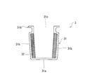
- FIG. 3 is a diagram illustrating the flavor source accommodation pod 3 according to the first embodiment.
- the flavor source accommodating pod 3 includes a heat resistant container 31 and a flavor source (flavor generating source) 32 accommodated in the heat resistant container 31.
- the heat-resistant container 31 is a metal container having a cup shape, and has a circular flat bottom surface 31a and a side surface 31b erected from the flat bottom surface 31a. Further, a vapor discharge port 31c as an open end is formed on the upper end side of the side surface 31b in the heat-resistant container 31.
- the flavor source 32 is not particularly limited as long as it is a material that releases a flavor when heated. In the present embodiment, for example, a tobacco cut, an aerosol base material, and a fragrance are kneaded.
- the flavor source accommodating pod 3 in the present embodiment is accommodated in the heat resistant container 31 with the flavor source 32 attached to the inside of the side surface 31 b of the heat resistant container 31.
- the accommodation form of the flavor source 32 in the heat-resistant container 31 is not particularly limited.
- the aerosol base material is a liquid that generates an aerosol when heated, and may be, for example, a propylene glycol solution.
- a hollow part 7 for disposing the flavor source accommodation pod 3 is provided in the front part of the power source part 2 in the casing 100, and the flavor source accommodation pod 3 is provided in the hollow part 7. Be placed.
- the installation method of the flavor source accommodation pod 3 in the hollow part 7 is not particularly limited.
- the flavor source accommodation pod 3 is installed in the hollow part 7 so that the vapor
- a chamber portion 8 is formed between the vapor discharge port 31 c of the flavor source accommodation pod 3 and the mouthpiece hole 200 of the mouthpiece 20.
- the chamber part 8 is a hollow part having a constant volume.
- the chamber portion 8 communicates with the vapor discharge port 31c and the suction hole 200, and the vapor component (flavor component) released from the vapor discharge port 31c when the flavor source 32 is evaporated by heating from the heating element 41 of the heater 4. It is the storage space for storing temporarily.
- the vapor discharge port 31 c of the flavor source accommodation pod 3 is opened only to the chamber portion 8.
- the chamber part 8 in the present embodiment includes a first chamber part 8A and a second chamber part 8B.
- the first chamber portion 8 ⁇ / b> A is a hollow storage space provided in the mouthpiece 20 and faces the mouthpiece hole 200.
- the second chamber portion 8B is a hollow storage space formed on the upper end side of the second casing 120, and faces the vapor discharge port 31c.
- the first chamber portion 8A and the second chamber portion 8B have a cylindrical shape, and the diameter of the second chamber portion 8B is larger than that of the first chamber portion 8A, but the shape is particularly limited.
- the ratio of the first chamber part 8A and the second chamber part 8B constituting the chamber part 8 is not particularly limited, and for example, the volume (volume) of either the first chamber part 8A or the second chamber part 8B is substantial. May be zero.
- the chamber portion 8 is substantially formed only by the first chamber portion 8A, and the volume (volume) of the second chamber portion 8B is substantially zero.
- the second casing 120 is provided with an air intake hole 9 that communicates the inside and outside of the chamber portion 8.
- two air intake holes 9 are provided in the second casing 120.
- the two air intake holes 9 are provided at the same height in the longitudinal direction (axial direction) of the non-combustion heating type smoking article 1.
- the two air intake holes 9 are provided at positions shifted by 180 ° in the circumferential direction around the central axis CL of the non-combustion heating type smoking article 1, and are arranged opposite to each other. It has become a relationship. That is, the two air intake holes 9 are arranged at point-symmetric positions with respect to the central axis CL of the non-combustion heating type smoking article 1.
- the electronic control unit 5 detects that the power switch 6 is turned on by the smoker, the electronic control unit 5 sends a control signal to the power supply unit 2. Then, energization of the heater 4 is started. As a result, the heating element 41 generates heat, and the heat-resistant container 31 of the flavor source accommodating pod 3 is heated. Thereby, when the flavor source 32 accommodated in the heat-resistant container 31 is heated, steam containing the flavor component evaporated from the flavor source 32 (hereinafter referred to as “flavor steam”) is released. The flavor steam generated by the evaporation of the flavor source 32 flows into the chamber portion 8 from the steam outlet 31c of the heat-resistant container 31 in the flavor source accommodation pod 3 and is temporarily stored in the chamber portion 8.
- the outside is introduced through the air intake holes 9 communicating with the inside and outside of the chamber portion 8. Air is taken into the chamber portion 8. In this way, the air that has flowed into the chamber portion 8 through each air intake hole 9 during suction forms an aerosol by mixing with the flavor vapor that is retained in the chamber portion 8, and the aerosol is applied to the mouthpiece 20. It is transported to the mouthpiece hole 200 and supplied into the mouth of the smoker through the mouthpiece hole 200.
- the chamber portion 8 for temporarily storing the vapor and the air intake hole 9 communicating between the inside and the outside of the chamber portion 8 are provided, and the vapor discharge port 31c of the flavor source accommodating pod 3 is provided only for the chamber portion 8 Since it is configured to open, the air taken into the chamber part 8 through the air intake hole 9 does not pass through the heat-resistant container 31 of the flavor source housing pod 3 and is stored in the chamber part 8. It can be mixed with steam and transported to the mouthpiece hole 200 of the mouthpiece 20.
- the heating element 41 of the heater 4 is heated at the time of heating. It is possible to suppress excessive evaporation of the flavor source 32 accommodated in the heat-resistant container 31. Thereby, it is prevented that the decrease rate of the flavor component in the flavor source 32 becomes excessively large, and the smoke amount and the intensity of the flavor are prevented from rapidly decreasing while the smoker repeatedly puffs (suctions). be able to.
- the smoke temperature a mixture temperature of aerosol and steam
- the amount of flavor components delivered for each suction is stabilized. Can be made.
- the chamber unit 8 has a volume that can store the flavor vapor evaporated from the flavor source 32 accommodated in the heat-resistant container 31 in an appropriate amount. Therefore, while adopting a non-venting structure that does not allow the air taken into the chamber portion 8 from the air intake hole 9 to be ventilated in the heat-resistant container 31, the evaporation of the flavor source 32 is moderately promoted and the amount of smoke is sufficient. Can be secured.
- the electronic control unit 5 is set so that the heat-resistant container 31 (or the ambient temperature in the heat-resistant container 31) is in the range of 150 ° C. to 250 ° C. when the power supply unit 2 is energized to the heater 4. Controls the power supply unit 2.
- the electronic control unit 5 uses the known temperature feedback control so that the heat resistant container 31 (or the ambient temperature in the heat resistant container 31) is maintained in the range of 150 ° C. to 250 ° C. from the power supply unit 2 to the heater 4.
- the energization to the can be controlled. In that case, you may monitor the temperature of the side surface 31b in the heat-resistant container 31, or the atmospheric temperature in the heat-resistant container 31 using a temperature sensor.
- the flavor source 32 can be appropriately atomized while suppressing the flavor source 32 (tobacco engraving) from burning.
- the non-combustion heating type smoking article 1 in this embodiment is provided with two air intake holes 9 in the chamber portion 8, and the two air intake holes 9 are the center of the non-combustion heating type smoking article 1. They are arranged opposite to each other in a point-symmetrical position with respect to the axis CL, that is, a position shifted 180 ° in the circumferential direction.
- the intake air collides at the center of the cross section of the chamber portion 8, and downwards (flavor source containing pod)
- the linear velocity of the intake air toward (three directions) can be reduced as compared with the case where the number of air intake holes is one.
- the air inflow rate which is the ratio of the amount of air that enters the flavor source accommodating pod 3 through the chamber 8 with respect to the total amount of intake air that flows into the chamber 8 from the air intake hole 9, is reduced. can do.
- the number of air intake holes 9 is large. As the number of air intake holes 9 increases, the amount of air flowing from one air intake hole 9 into the chamber portion 8 decreases under the condition that the suction amount of the smoker is constant. The linear velocity of the intake air flowing into the chamber portion 8 from the intake hole 9 becomes slow. As a result, the intake air flowing into the chamber portion 8 from the air intake hole 9 can be made difficult to enter the flavor source accommodating pod 3. Thereby, the smoke temperature does not rise excessively, and the non-combustion heating type smoking article 1 in which the amount of flavor components delivered for each suction is stable can be provided more suitably.
- the electronic control unit 5 sends a control signal to the power source unit 2 to start energization of the heater 4 when the power switch 6 is turned on by the smoker.
- the electronic control unit 5 sends a control signal to the power source unit 2 to end the energization from the power source unit 2 to the heater 4.
- the energization start condition is established when the power switch 6 is turned on
- the energization end condition is established when the power switch 6 is turned off
- the energization start condition is established.
- the power supply from the power supply unit 2 to the heater 4 is continuously continued over the energization period until the end condition is satisfied.
- the heater 4 has a heating element 41 that heats the side surface of the flavor source accommodating pod 3, and the heater 4 is not disposed in the chamber portion 8. Since it is adopted, there is an advantage that the aerosol staying in the chamber portion 8, that is, the flavor intake air can be cooled. Further, in the non-combustion heating type smoking article 1, a cooling member for cooling the vapor component of the flavor source 32 is not particularly provided in the chamber portion 8. Since the non-combustion heating type smoking article 1 can suppress the temperature of the flavor steam from becoming excessively high by adopting the above-described heating part non-venting structure, there is no need to provide a cooling member in the chamber part 8 and smoking Devices can be manufactured at a lower cost.
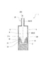
- FIG. 4A is a diagram illustrating a schematic structure of the device according to the first embodiment.
- FIG. 4B is a diagram conceptually illustrating a flow of intake air in the device according to the first embodiment.
- 5A is a diagram illustrating a schematic structure of a device according to Comparative Example 1.
- FIG. 5B is a diagram conceptually showing the flow of intake air in the device of Comparative Example 1;
- Example 1 shown in FIG. 4A and FIG. 4B is a heating unit non-venting type device simulating the non-combustion heating type smoking article 1 according to this embodiment, and a flavor source containing pod in which no vent hole is formed on the bottom surface. 3 and the mouthpiece 20 is provided with two air intake holes 9 having a hole diameter of 0.5 mm ⁇ at a height of 7 mm from the upper opening end (steam discharge port) 31c of the flavor source accommodating pod 3.
- the ratio of the length from the vapor discharge port 31c to the air intake hole 9 to the length from the vapor discharge port 31c to the suction hole 200 (the upper end of the first chamber portion 8A) hereinafter referred to as “air”).
- the ratio of the opening height of the intake hole ” is 20%.
- the volume (volume) of the chamber part 8 (first chamber part 8A) in the flow path from the upper opening end (vapor discharge port) 31c of the flavor source accommodation pod 3 to the air intake hole 9 is 0.4 mL. It was.
- the chamber portion 8 is substantially composed only of the first chamber portion 8A (internal space of the mouthpiece 20), and the volume (volume) of the second chamber portion 8B is substantially zero. It is.
- Comparative Example 1 shown in FIGS. 5A and 5B is formed as a heating part ventilation type device in which a ventilation hole having a diameter of 2 mm is formed at the bottom of the flavor source accommodating pod 3.
- the entry hole 9 is not formed.
- the volume of the cavity portion obtained by subtracting the volume occupied by the flavor source (mixture of tobacco and aerosol base material) 32 from the volume of the flavor source containing pod 3 is 0.3 mL in both Example 1 and Comparative Example 1. is there.
- Fig. 6 shows a list of verification test conditions and flavor source specifications for the smoke temperature rise suppression effect.
- a smoking test was performed on each device of Example 1 and Comparative Example 1 configured as described above using a smoking machine (Borgwaldt, RM-26). The smoke absorption flow rate in the smoking test was 55 mL / 2 seconds, and the smoking interval was 30 seconds.
- a desktop temperature control unit Chino Steel Corporation: SY2111-30
- K thermocouple were used for temperature control of each device during the smoking test. Installed so that the K thermocouple touches the surface of the flavor source (cigarette carved) 32 in the flavor source accommodating pod 3, and set the temperature rising profile so that the heater reaches the target temperature range (200 ° C.) in 120 seconds. After reaching the target temperature range, PID control was performed by measuring the temperature of the flavor source (cigarette carving) 32 in real time.
- Example 7 is a diagram showing measurement results of smoke temperature history of Comparative Example 1.
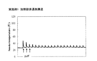
- FIG. 8 is a diagram showing the measurement results of the smoke temperature history of Example 1.
- Comparative Example 1 in which the heating part ventilation structure was adopted, the smoke temperature reached 100 ° C. at the first puff, and became constant at about 60 ° C. after the fifth puff.
- Example 1 adopting the heating part non-venting structure the maximum temperature of the first puff was 50 ° C.
- Example 1 that adopts the heating part non-venting structure compared to Comparative Example 1 that adopts the heating part ventilation structure. Moreover, according to Example 1, it has confirmed that it became possible to maintain the smoke temperature at the time of smoking in the temperature range near normal temperature, without providing the smoke cooling mechanism for cooling smoke separately.
- FIG. 9 is a diagram showing the amount of total particulate matter contained in aerosol and vapor aspirated by a smoking machine during the smoking test for Example 1 and Comparative Example 1.
- the vertical axis represents the amount of total particulate matter (TPM), and the horizontal axis represents the number of puffs.
- Example 1 which employ
- Example 1 which employ
- the reduction rate of total particulate matter (TPM) contained in aerosols and vapors during smoking (hereinafter referred to as “TPM reduction rate”) is defined by the following formula. While the TPM reduction rate in Example 1 was 0.91, the TPM reduction rate in Example 1 employing the heating part non-venting structure was 0.61.
- the small TPM reduction rate indicates that the decrease in the component delivery amount from the first puff to the tenth puff is small (stable).
- the heating part non-venting structure (Example 1) has a smaller TPM reduction rate than the heating part venting structure (Comparative Example 1), the heating part non-venting structure (Example 1) is more stable. It can be said that the ingredients can be delivered.
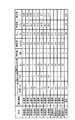
- FIG. 10 shows a list of specifications of Examples 1 to 12 and Comparative Example 1.
- FIG. 10 also shows the air inflow rate R pod for Examples 1 to 12 and Comparative Example 1, and the smoke temperature and TPM reduction rate for Examples 1 to 8 and Comparative Example 1. Details of the air inflow rate R pod will be described later.
- the “opening position (mm)” in FIG. 10 is a separation dimension from the upper opening end (steam discharge port) 31 c of the flavor source accommodating pod 3 to the air intake hole 9.
- aperture height ratio (%) in FIG.
- the 10 means “aperture height ratio of the air intake hole”. As described above, from the steam discharge port 31 c to the suction hole 200. It is the ratio of the length from the vapor discharge port 31c to the air intake hole 9 with respect to the length up to (the upper end of the first chamber portion 8A).
- the two air intake holes 9 are opposed to each other at a position shifted by 180 ° in the circumferential direction around the central axis of the device. Further, with respect to Example 9, the four air intake holes 9 are arranged at positions shifted by 90 ° in the circumferential direction around the central axis of the device.
- FIG. 11 shows a schematic structure of a device according to Examples 2 to 4.
- the volume of the chamber portion 8 in the first embodiment (the total volume of the first chamber portion 8A and the second chamber portion) is 0.4 mL
- the volume of the chamber portion 8 in the second to fourth embodiments (the first volume)
- the total volume of the chamber portion 8A and the second chamber portion) is 2.1 mL, 3.5 mL, and 7.9 mL, respectively.
- the flavor source accommodating pod 3 in Examples 2 to 4 is the same as the flavor source accommodating pod 3 in Example 1 described with reference to FIG. 4A.
- FIG. 12 is a graph showing the measurement results of the amount of total particulate matter (TPM) when a smoking test was performed on Examples 1 to 4.
- TPM total particulate matter
- the chamber part 8 having a certain volume (for example, the volume of the chamber part 8 is 2.1 mL) or more.
- the volume of the chamber portion 8 is preferably 20 mL or less.
- FIG. 13 is a diagram showing measurement results of the amount of total particulate matter (TPM) when a smoking test was performed on Examples 1, 2, and 5.
- FIG. 14 is a diagram showing measurement results of the amount of total particulate matter (TPM) when a smoking test was performed on Examples 1, 3, and 6.
- FIG. 15 is a diagram showing measurement results of the amount of total particulate matter (TPM) when a smoking test was performed on Examples 1, 4, 7, and 8.
- the volume of the chamber portion 8 is 7.9 mL, and the opening position of the air intake hole 9 is 43 mm (the “opening height ratio of the air intake hole” is 63%).
- a sufficient component delivery amount could be maintained up to about the 15th puff. This is considered to be because the suction amount of the vapor of the flavor component accumulated in the chamber portion 8 is suppressed by moving the position of the air intake hole 9 away from the flavor source accommodation pod 3. Therefore, the chamber portion 8 is provided by setting the air intake hole 9 at a position where the volume of the chamber portion 8 is 7.9 mL or more and the opening height ratio of the air intake hole 9 is 63% or more. It can be said that it is preferable to increase the evaporation amount of the flavor component and stabilize the component delivery amount, compared to the structure having no structure.
- the air inflow rate Rpod into the flavor source accommodating pod 3 in each example and comparative example 1 is compared.
- the air inflow rate Rpod enters the flavor source accommodation pod 3 through the chamber part 8 with respect to the total air quantity of the intake air flowing into the chamber part from the air intake hole 9 in 2 seconds when the smoke is absorbed by the smoking machine. It is the ratio of air volume, and was calculated by fluid analysis.
- the wall surface of the flavor source accommodating pod 3 (heat resistant container 31) and the space inside the pod are set to 500 Kelvin, and other spaces are set to the initial condition of 300 Kelvin.
- the fluid analysis was conducted.
- Fluent version 18.0 (ANSYS) was used for fluid analysis, and analysis was performed under a sine profile with a smoke absorption flow rate of 55 mL / 2 seconds. Further, the air inflow rate Rpod (%) into the flavor source accommodating pod 3 was calculated using the following equation.
- Vpod is the volume of air that has entered the flavor source accommodating pod 3 during 2 seconds when the smoke is absorbed by the smoking machine
- V inhalation is the smoke absorption capacity, which is a constant value of 55 mL.
- the air that enters (inflows) into the flavor source accommodation pod 3 and the air that flows out from the flavor source accommodation pod 3 are counted simultaneously, and the air that enters the flavor source accommodation pod 3 from that value. Therefore, the real value was multiplied by 0.5 in the calculation of the air inflow rate Rpod.
- the analysis result is as shown in FIG.
- the air inflow rate Rpod of Example 1 was 0.15%, and it was confirmed that almost no air entered the flavor source accommodating pod 3.
- the air inflow rate Rpod is 10% or more higher than in the other examples. This is due to the downward flow of air generated by the intake air that has flowed in from the two air intake holes 9 arranged at the opposing positions in the chamber portion 8 in the chamber portion 8, and the flavor source accommodating pod 3. This is thought to be due to the intrusion of intake air.
- FIG. 16 shows a fluid path line of intake air in the device according to the second embodiment.
- Example 5 to 8 where the opening position of the air intake hole 9 is far from the flavor source accommodating pod 3, the downward airflow generated when the intake air collides with the central portion of the chamber portion 8 is generated.
- the result was that the air source rate Rpod was 1% or less without reaching the flavor source accommodating pod 3.
- the four air intake holes 9 are arranged at positions shifted by 90 ° in the circumferential direction around the central axis CL of the smoking device.
- the air inflow rate Rpod the same tendency as in Example 1 in which the number of air intake holes 9 was two was observed.
- Example 1 (Rpod: 0.
- the air inflow rate Rpod was higher in Example 10 (Rpod: 12.4%) having one air intake hole 9 than in 15%. This is because the embodiment 10 with one air intake hole 9 is more externally connected to the chamber portion 8 through the air intake hole 9 during suction (puff) than the embodiment 1 with two air intake holes 9.
- the linear velocity of the air flowing into the chamber increases, and in the embodiment 10 with one air intake hole 9, the air that has flowed in from the air intake hole 9 faces the air intake hole 9.
- Example 11 when the aperture diameter (diameter) of the air intake hole 9 was changed, the linear velocity of the intake air in Example 11 with an aperture diameter of 0.2 mm was about that of Example 12 with an aperture diameter of 0.8 mm.
- the air inflow rate Rpod of Example 11 is increased because the airflow in the direction of the flavor source accommodating pod 3 is remarkably formed, but the Rpod itself is 1% or less, so the influence of the opening diameter is It was confirmed that it was small.
- the air inflow rate Rpod If it is 25% or less, it can be considered that it has the characteristics of the non-venting structure of the heating part sufficiently. More preferably, the air inflow rate Rpod is 15% or less, and more preferably the air inflow rate Rpod is 1% or less.
- the volume of the chamber portion 8 (the total volume of the first chamber portion 8A and the second chamber portion 8B) is preferably 2.1 mL or more, and more preferably 7.9 mL or more.
- the height at which the air intake hole 9 is provided in the chamber 8 is higher, that is, the height ratio of the air intake hole 9 (the length from the vapor discharge port 31c to the suction port 200).
- the ratio of the length from the vapor discharge port 31c to the air intake hole 9) is preferably as large as possible, and the opening height ratio of the air intake hole 9 is preferably 63% or more.
- a reasonable range is that the height ratio of the air intake holes 9 is 90% or less.
- about the aperture diameter (diameter) of the air intake hole 9 it can illustrate as a preferable range that it shall be 0.2 mm or more and 0.8 mm or less.
- the smoke temperature in Comparative Example 1 exceeds 100 ° C., whereas the smoke temperature in Examples 1 to 12 is maintained at 60 ° C. or lower.
- the temperature of the vapor component of the flavor source 32 at the time of smoke absorption is set to 60 ° C. or less, it is possible to supply aerosol in a temperature range in which smokers can easily smoke.
- the air intake hole 9 in the non-combustion heating type smoking article 1 in the present embodiment is such that the inflow direction (the axial direction of the air intake hole 9) when air flows into the chamber portion 8 is relative to the central axis CL.
- the inflow direction (the axial direction of the air intake hole 9) when air flows into the chamber portion 8 is the suction of the mouthpiece 20.
- the intake air that has flowed into the chamber portion 8 from the air intake hole 9 is more difficult to enter the flavor source accommodating pod 3, it is more preferable to suppress the increase in smoke temperature and to stably supply the flavor components. Can be realized.
Abstract
L'invention concerne une technologie associée à un article à fumer de type à chauffage sans combustion, dans lequel la température de fumée n'augmente pas excessivement et la quantité d'un élément d'arôme qui est délivré pendant chaque aspiration est stable. L'article à fumer de type à chauffage sans combustion comprend : un embout buccal comportant un trou d'orifice d'aspiration ; une section de réception de source d'arôme, qui reçoit une source d'arôme, et qui comporte un orifice d'évacuation de vapeur qui évacue un élément de vapeur dégagé par l'évaporation de la source d'arôme ; un dispositif de chauffage, destiné à chauffer et à évaporer la source d'arôme ; une partie chambre, destinée à établir une communication entre l'orifice d'évacuation de vapeur et le trou d'orifice d'aspiration, et à stocker temporairement l'élément de vapeur dégagé par l'évaporation de la source d'arôme ; et un trou d'admission d'air, qui établit une communication entre l'intérieur et l'extérieur de la partie chambre. L'orifice d'évacuation de vapeur permet un accès uniquement à la partie chambre, et pendant chaque aspiration, l'élément de vapeur, qui s'est accumulé dans la partie chambre, est mélangé avec de l'air d'admission qui s'est introduit dans la partie chambre à partir du trou d'admission d'air, et est ensuite transporté vers le trou d'orifice d'aspiration.
Priority Applications (5)
| Application Number | Priority Date | Filing Date | Title |
|---|---|---|---|
| CN201880090809.4A CN111902056A (zh) | 2018-03-05 | 2018-03-05 | 非燃烧加热型吸烟物品 |
| PCT/JP2018/008255 WO2019171417A1 (fr) | 2018-03-05 | 2018-03-05 | Article à fumer de type à chauffage sans combustion |
| JP2020504482A JP6921304B2 (ja) | 2018-03-05 | 2018-03-05 | 非燃焼加熱型喫煙物品 |
| EP18908323.1A EP3763230A4 (fr) | 2018-03-05 | 2018-03-05 | Article à fumer de type à chauffage sans combustion |
| US16/992,586 US20200367560A1 (en) | 2018-03-05 | 2020-08-13 | Non-combustion heating-type smoking article |
Applications Claiming Priority (1)
| Application Number | Priority Date | Filing Date | Title |
|---|---|---|---|
| PCT/JP2018/008255 WO2019171417A1 (fr) | 2018-03-05 | 2018-03-05 | Article à fumer de type à chauffage sans combustion |
Related Child Applications (1)
| Application Number | Title | Priority Date | Filing Date |
|---|---|---|---|
| US16/992,586 Continuation US20200367560A1 (en) | 2018-03-05 | 2020-08-13 | Non-combustion heating-type smoking article |
Publications (1)
| Publication Number | Publication Date |
|---|---|
| WO2019171417A1 true WO2019171417A1 (fr) | 2019-09-12 |
Family
ID=67846526
Family Applications (1)
| Application Number | Title | Priority Date | Filing Date |
|---|---|---|---|
| PCT/JP2018/008255 WO2019171417A1 (fr) | 2018-03-05 | 2018-03-05 | Article à fumer de type à chauffage sans combustion |
Country Status (5)
| Country | Link |
|---|---|
| US (1) | US20200367560A1 (fr) |
| EP (1) | EP3763230A4 (fr) |
| JP (1) | JP6921304B2 (fr) |
| CN (1) | CN111902056A (fr) |
| WO (1) | WO2019171417A1 (fr) |
Cited By (3)
| Publication number | Priority date | Publication date | Assignee | Title |
|---|---|---|---|---|
| EP3794977A1 (fr) * | 2019-09-20 | 2021-03-24 | Nerudia Limited | Appareil de substitution du tabac |
| EP3795004A1 (fr) * | 2019-09-20 | 2021-03-24 | Nerudia Limited | Appareil de substitution du tabac |
| WO2023148910A1 (fr) * | 2022-02-04 | 2023-08-10 | 日本たばこ産業株式会社 | Inhalateur d'arôme et système à fumer |
Families Citing this family (2)
| Publication number | Priority date | Publication date | Assignee | Title |
|---|---|---|---|---|
| EP4304398A1 (fr) * | 2021-03-10 | 2024-01-17 | JT International SA | Article consommable à réceptacle ouvert pour un dispositif de génération d'aérosol |
| CN216088865U (zh) * | 2021-09-24 | 2022-03-22 | 比亚迪精密制造有限公司 | 电子烟雾化装置及电子烟 |
Citations (3)
| Publication number | Priority date | Publication date | Assignee | Title |
|---|---|---|---|---|
| WO2013120565A2 (fr) | 2012-02-13 | 2013-08-22 | Philip Morris Products S.A. | Article produisant un aérosol ayant un élément de refroidissement d'aérosol |
| WO2017108721A1 (fr) * | 2015-12-21 | 2017-06-29 | Philip Morris Products S.A. | Système de génération d'aérosol comprenant une entrée d'air variable |
| WO2017153270A1 (fr) * | 2016-03-08 | 2017-09-14 | Hauni Maschinenbau Gmbh | Cigarette électronique et cartouche pour cigarette électronique |
Family Cites Families (19)
| Publication number | Priority date | Publication date | Assignee | Title |
|---|---|---|---|---|
| US5060671A (en) * | 1989-12-01 | 1991-10-29 | Philip Morris Incorporated | Flavor generating article |
| JP3325028B2 (ja) * | 1996-06-17 | 2002-09-17 | 日本たばこ産業株式会社 | 香味生成物品 |
| KR100289448B1 (ko) * | 1997-07-23 | 2001-05-02 | 미즈노 마사루 | 향미발생장치 |
| CA2595831C (fr) * | 2005-02-02 | 2013-08-06 | Oglesby & Butler Research & Development Limited | Dispositif pour vaporiser de la matiere vaporisable |
| US9675109B2 (en) * | 2005-07-19 | 2017-06-13 | J. T. International Sa | Method and system for vaporization of a substance |
| EP2817051B1 (fr) * | 2012-02-22 | 2017-07-26 | Altria Client Services LLC | Article à fumer électronique |
| KR20160040444A (ko) * | 2013-03-15 | 2016-04-14 | 알트리아 클라이언트 서비시즈 엘엘씨 | 전자 흡연 용품 |
| WO2015009862A2 (fr) * | 2013-07-19 | 2015-01-22 | Altria Client Services Inc. | Formulation d'aérosol liquide pour un article à fumer électronique |
| EA038319B1 (ru) * | 2013-07-25 | 2021-08-09 | Олтриа Клайент Сервисиз Ллк | Электронное изделие для курения |
| PL3498115T3 (pl) * | 2013-12-23 | 2021-12-20 | Juul Labs International Inc. | Systemy urządzeń do odparowywania |
| US10039311B2 (en) * | 2014-10-17 | 2018-08-07 | Securience, LLC | Tobacco extract for non-combustible smoking devices |
| GB201418817D0 (en) * | 2014-10-22 | 2014-12-03 | British American Tobacco Co | Apparatus and method for generating an inhalable medium, and a cartridge for use therewith |
| PL3232836T3 (pl) * | 2014-12-15 | 2019-03-29 | Philip Morris Products Sa | Układ wytwarzania aerozolu zawierający ruchomy wkład |
| CN106263031A (zh) * | 2015-05-15 | 2017-01-04 | 深圳市新宜康科技有限公司 | 锁紧防漏电子烟装置 |
| EP3158881B1 (fr) * | 2015-10-22 | 2018-05-23 | Xiaochun Zhu | Cigarettes électroniques ayant un réservoir e-liquide compressible |
| RU2713326C2 (ru) * | 2015-11-02 | 2020-02-04 | Филип Моррис Продактс С.А. | Генерирующая аэрозоль система, содержащая вибрационный элемент |
| EA201892756A1 (ru) * | 2016-05-27 | 2019-04-30 | Джапан Тобакко Инк. | Табачное наполнение для нагревательного курительного изделия негорючего типа |
| EA201990141A1 (ru) * | 2016-06-27 | 2019-06-28 | Джапан Тобакко Инк. | Картридж ароматического ингалятора и ароматический ингалятор, содержащий картридж ароматического ингалятора |
| CN109475191B (zh) * | 2016-07-25 | 2022-07-22 | 菲利普莫里斯生产公司 | 加热器管理 |
-
2018
- 2018-03-05 WO PCT/JP2018/008255 patent/WO2019171417A1/fr unknown
- 2018-03-05 EP EP18908323.1A patent/EP3763230A4/fr active Pending
- 2018-03-05 CN CN201880090809.4A patent/CN111902056A/zh active Pending
- 2018-03-05 JP JP2020504482A patent/JP6921304B2/ja active Active
-
2020
- 2020-08-13 US US16/992,586 patent/US20200367560A1/en active Pending
Patent Citations (3)
| Publication number | Priority date | Publication date | Assignee | Title |
|---|---|---|---|---|
| WO2013120565A2 (fr) | 2012-02-13 | 2013-08-22 | Philip Morris Products S.A. | Article produisant un aérosol ayant un élément de refroidissement d'aérosol |
| WO2017108721A1 (fr) * | 2015-12-21 | 2017-06-29 | Philip Morris Products S.A. | Système de génération d'aérosol comprenant une entrée d'air variable |
| WO2017153270A1 (fr) * | 2016-03-08 | 2017-09-14 | Hauni Maschinenbau Gmbh | Cigarette électronique et cartouche pour cigarette électronique |
Non-Patent Citations (1)
| Title |
|---|
| See also references of EP3763230A4 |
Cited By (3)
| Publication number | Priority date | Publication date | Assignee | Title |
|---|---|---|---|---|
| EP3794977A1 (fr) * | 2019-09-20 | 2021-03-24 | Nerudia Limited | Appareil de substitution du tabac |
| EP3795004A1 (fr) * | 2019-09-20 | 2021-03-24 | Nerudia Limited | Appareil de substitution du tabac |
| WO2023148910A1 (fr) * | 2022-02-04 | 2023-08-10 | 日本たばこ産業株式会社 | Inhalateur d'arôme et système à fumer |
Also Published As
| Publication number | Publication date |
|---|---|
| JPWO2019171417A1 (ja) | 2021-02-04 |
| CN111902056A (zh) | 2020-11-06 |
| JP6921304B2 (ja) | 2021-08-18 |
| US20200367560A1 (en) | 2020-11-26 |
| EP3763230A4 (fr) | 2021-10-27 |
| EP3763230A1 (fr) | 2021-01-13 |
Similar Documents
| Publication | Publication Date | Title |
|---|---|---|
| WO2019171417A1 (fr) | Article à fumer de type à chauffage sans combustion | |
| TWI654944B (zh) | 在氣溶膠產生系統中產生氣溶膠之方法及氣溶膠產生系統 | |
| KR102592719B1 (ko) | 가열 요소로 기재를 전달하기 위하여 벤츄리 효과를 이용하는 에어로졸-발생 시스템 | |
| KR102596888B1 (ko) | 에어로졸 제공 디바이스 | |
| JP6176737B2 (ja) | 物質を蒸発させるための方法とシステム | |
| CN110710727B (zh) | 蒸发装置系统和方法 | |
| KR20200057490A (ko) | 에어로졸 생성 장치 및 시스템 | |
| JP2019533454A (ja) | エアロゾル供給物品 | |
| BR112018016413B1 (pt) | Dispositivos vaporizadores com discriminação de sopro | |
| RU2751056C1 (ru) | Устройство для нагревания аэрозольобразующего материала, устройство для испарения аэрозольобразующего материала и система для выработки потока аэрозоля | |
| US11266181B2 (en) | Heating-type flavor inhaler | |
| TW201338718A (zh) | 吸入器組件 | |
| TW201317014A (zh) | 吸入器 | |
| JP2022506514A (ja) | 気化器デバイス用のカートリッジ | |
| CN113226080A (zh) | 用于蒸发器装置的料筒 | |
| CN112584716A (zh) | 气溶胶生成装置 | |
| US20210252239A1 (en) | Flavor aspirator | |
| TWI741161B (zh) | 非燃燒加熱型抽煙物品 | |
| CN113631056A (zh) | 用于蒸发器装置的料盒 | |
| KR20210089683A (ko) | 기화기 디바이스용 카트리지 | |
| EP3906074A1 (fr) | Cartouches pour dispositifs de vaporisation | |
| KR20200122668A (ko) | 에어로졸 생성 장치 | |
| KR20240053587A (ko) | 응축 관리 기능을 갖는 마우스피스 | |
| KR20240053046A (ko) | 감각 매체를 갖는 마우스피스를 갖는 에어로졸 발생 시스템 | |
| KR20230052975A (ko) | 에어로졸 제공 시스템 |
Legal Events
| Date | Code | Title | Description |
|---|---|---|---|
| 121 | Ep: the epo has been informed by wipo that ep was designated in this application |
Ref document number: 18908323 Country of ref document: EP Kind code of ref document: A1 |
|
| ENP | Entry into the national phase |
Ref document number: 2020504482 Country of ref document: JP Kind code of ref document: A |
|
| NENP | Non-entry into the national phase |
Ref country code: DE |
|
| ENP | Entry into the national phase |
Ref document number: 2018908323 Country of ref document: EP Effective date: 20201005 |