WO2019167283A1 - Electrode for redox-flow batteries, redox-flow battery cell, and redox-flow battery - Google Patents
Electrode for redox-flow batteries, redox-flow battery cell, and redox-flow battery Download PDFInfo
- Publication number
- WO2019167283A1 WO2019167283A1 PCT/JP2018/008167 JP2018008167W WO2019167283A1 WO 2019167283 A1 WO2019167283 A1 WO 2019167283A1 JP 2018008167 W JP2018008167 W JP 2018008167W WO 2019167283 A1 WO2019167283 A1 WO 2019167283A1
- Authority
- WO
- WIPO (PCT)
- Prior art keywords
- electrode
- carbon fiber
- cell
- flow battery
- fiber
- Prior art date
Links
Images


Classifications
-
- H—ELECTRICITY
- H01—ELECTRIC ELEMENTS
- H01M—PROCESSES OR MEANS, e.g. BATTERIES, FOR THE DIRECT CONVERSION OF CHEMICAL ENERGY INTO ELECTRICAL ENERGY
- H01M8/00—Fuel cells; Manufacture thereof
- H01M8/18—Regenerative fuel cells, e.g. redox flow batteries or secondary fuel cells
- H01M8/184—Regeneration by electrochemical means
- H01M8/188—Regeneration by electrochemical means by recharging of redox couples containing fluids; Redox flow type batteries
-
- H—ELECTRICITY
- H01—ELECTRIC ELEMENTS
- H01M—PROCESSES OR MEANS, e.g. BATTERIES, FOR THE DIRECT CONVERSION OF CHEMICAL ENERGY INTO ELECTRICAL ENERGY
- H01M4/00—Electrodes
- H01M4/02—Electrodes composed of, or comprising, active material
- H01M4/04—Processes of manufacture in general
- H01M4/0471—Processes of manufacture in general involving thermal treatment, e.g. firing, sintering, backing particulate active material, thermal decomposition, pyrolysis
-
- H—ELECTRICITY
- H01—ELECTRIC ELEMENTS
- H01M—PROCESSES OR MEANS, e.g. BATTERIES, FOR THE DIRECT CONVERSION OF CHEMICAL ENERGY INTO ELECTRICAL ENERGY
- H01M4/00—Electrodes
- H01M4/86—Inert electrodes with catalytic activity, e.g. for fuel cells
- H01M4/8605—Porous electrodes
- H01M4/8626—Porous electrodes characterised by the form
- H01M4/8631—Bipolar electrodes
-
- H—ELECTRICITY
- H01—ELECTRIC ELEMENTS
- H01M—PROCESSES OR MEANS, e.g. BATTERIES, FOR THE DIRECT CONVERSION OF CHEMICAL ENERGY INTO ELECTRICAL ENERGY
- H01M4/00—Electrodes
- H01M4/86—Inert electrodes with catalytic activity, e.g. for fuel cells
- H01M4/96—Carbon-based electrodes
-
- H—ELECTRICITY
- H01—ELECTRIC ELEMENTS
- H01M—PROCESSES OR MEANS, e.g. BATTERIES, FOR THE DIRECT CONVERSION OF CHEMICAL ENERGY INTO ELECTRICAL ENERGY
- H01M4/00—Electrodes
- H01M4/86—Inert electrodes with catalytic activity, e.g. for fuel cells
- H01M2004/8678—Inert electrodes with catalytic activity, e.g. for fuel cells characterised by the polarity
- H01M2004/8694—Bipolar electrodes
-
- Y—GENERAL TAGGING OF NEW TECHNOLOGICAL DEVELOPMENTS; GENERAL TAGGING OF CROSS-SECTIONAL TECHNOLOGIES SPANNING OVER SEVERAL SECTIONS OF THE IPC; TECHNICAL SUBJECTS COVERED BY FORMER USPC CROSS-REFERENCE ART COLLECTIONS [XRACs] AND DIGESTS
- Y02—TECHNOLOGIES OR APPLICATIONS FOR MITIGATION OR ADAPTATION AGAINST CLIMATE CHANGE
- Y02E—REDUCTION OF GREENHOUSE GAS [GHG] EMISSIONS, RELATED TO ENERGY GENERATION, TRANSMISSION OR DISTRIBUTION
- Y02E60/00—Enabling technologies; Technologies with a potential or indirect contribution to GHG emissions mitigation
- Y02E60/10—Energy storage using batteries
-
- Y—GENERAL TAGGING OF NEW TECHNOLOGICAL DEVELOPMENTS; GENERAL TAGGING OF CROSS-SECTIONAL TECHNOLOGIES SPANNING OVER SEVERAL SECTIONS OF THE IPC; TECHNICAL SUBJECTS COVERED BY FORMER USPC CROSS-REFERENCE ART COLLECTIONS [XRACs] AND DIGESTS
- Y02—TECHNOLOGIES OR APPLICATIONS FOR MITIGATION OR ADAPTATION AGAINST CLIMATE CHANGE
- Y02E—REDUCTION OF GREENHOUSE GAS [GHG] EMISSIONS, RELATED TO ENERGY GENERATION, TRANSMISSION OR DISTRIBUTION
- Y02E60/00—Enabling technologies; Technologies with a potential or indirect contribution to GHG emissions mitigation
- Y02E60/30—Hydrogen technology
- Y02E60/50—Fuel cells
Definitions
- the present invention relates to an electrode for a redox flow battery, a redox flow battery cell, and a redox flow battery.
- RF batteries redox flow batteries
- Patent Documents 1 and 2 redox flow batteries
- an RF battery uses a cell stack in which a plurality of cell frames, positive electrodes, diaphragms, and negative electrodes are stacked.
- the cell frame includes a bipolar plate disposed between the positive electrode and the negative electrode, and a frame provided on the outer periphery of the bipolar plate.
- positive and negative electrodes are arranged between bipolar plates of adjacent cell frames with a diaphragm interposed therebetween to form one cell.
- An RF battery performs charging / discharging by circulating an electrolyte in a cell in which an electrode is built.
- the electrode of the redox flow battery functions as a reaction field that promotes the battery reaction of the active material (metal ions) contained in the electrolytic solution.
- carbon fiber aggregates for example, carbon felt
- PAN-based carbon fibers made from polyacrylonitrile (PAN) fibers are used. Is often used (see, for example, Patent Documents 2 to 4).
- JP 2013-232434 A Japanese Patent Laying-Open No. 2015-190066 JP-A-8-287923 JP 2001-85025 A
- the electrode for the redox flow battery of the present disclosure is: An electrode for a redox flow battery formed of a carbon fiber assembly including a plurality of carbon fibers, The carbon fiber has a plurality of wrinkles on the surface, L 1 the peripheral length of the cross section of the carbon fibers, when the circumferential length of a virtual rectangle circumscribing the cross-section of the carbon fiber and L 2, L 1 and a ratio L 1 / L 2 and L 2 is 1 greater .
- the redox flow battery cell of the present disclosure is The redox flow battery electrode of the present disclosure is provided.
- the redox flow battery of the present disclosure is The redox flow battery cell of the present disclosure is provided.
- a carbon fiber constituting a carbon fiber assembly that is a material for an electrode for a redox flow battery uses a circular cross-sectional fiber having a substantially circular cross-sectional shape (a cross-sectional shape perpendicular to the longitudinal direction of the fiber). It was.
- One way to improve the battery performance of a redox flow battery is to reduce the reaction resistance of the electrode.
- the cross-sectional shape of the carbon fiber is circular, the reaction area in contact with the electrolytic solution is small, and it is difficult to reduce the reaction resistance of the electrode.
- an object of the present disclosure is to provide a redox flow battery electrode that can reduce the reaction resistance of the electrode. Another object of the present disclosure is to provide a redox flow battery cell and a redox flow battery excellent in battery performance.
- the present inventors propose to use a modified cross-section fiber having a plurality of wrinkles on the fiber surface as the carbon fiber constituting the electrode of the carbon fiber assembly.
- the specific surface area of a fiber can be enlarged, the reaction area which contacts electrolyte solution can be increased, and the reactivity with electrolyte solution can be improved. Therefore, the reaction resistance of the electrode can be reduced, and the battery performance can be improved.
- the electrode for a redox flow battery according to the embodiment is An electrode for a redox flow battery formed of a carbon fiber assembly including a plurality of carbon fibers, The carbon fiber has a plurality of wrinkles on the surface, L 1 the peripheral length of the cross section of the carbon fibers, when the circumferential length of a virtual rectangle circumscribing the cross-section of the carbon fiber and L 2, L 1 and a ratio L 1 / L 2 and L 2 is 1 greater .
- the above redox flow battery electrode by being formed of carbon fiber aggregates, there are voids in the electrode, and the electrolytic solution can flow and penetrate and diffuse in the electrode. it can. Therefore, the reaction area between the electrode and the electrolytic solution increases, and it is easy to secure a reaction field. Furthermore, by having a plurality of wrinkles on the surface of the carbon fiber constituting the carbon fiber aggregate, the surface area of the fiber can be increased, the reaction area in contact with the electrolytic solution can be increased, and the reactivity with the electrolytic solution can be improved.
- the ratio L 1 / L 2 between the circumferential length (L 1 ) of the cross section of the carbon fiber and the circumferential length (L 2 ) of the virtual rectangle circumscribing the cross section of the carbon fiber is more than 1, so that the fiber
- the specific surface area is large, the reaction area in contact with the electrolytic solution can be sufficiently secured, and the reactivity with the electrolytic solution is improved. Therefore, the electrode for the redox flow battery can reduce the reaction resistance of the electrode.
- the upper limit of L 1 / L 2 is, for example, 2 or less.
- Cross section of carbon fiber refers to a cross section perpendicular to the longitudinal direction of the fiber.
- the virtual rectangle circumscribing the cross section of the carbon fiber is obtained as follows. As shown in FIG. 4, the outline of the cross section of the carbon fiber 40 is specified. And when the outline of the fiber 40 is sandwiched between a pair of parallel lines, after obtaining a set of parallel lines where the distance between the parallel lines is the minimum distance, the outline of the fiber 40 is sandwiched between a pair of parallel lines orthogonal to the pair. In this case, a set of parallel lines having the maximum distance between the parallel lines is obtained, and a rectangle surrounded by the two sets of parallel lines is defined as a virtual rectangle R.
- the short side length a of the virtual rectangle R is the short diameter of the carbon fiber 40
- the long side length b is the long diameter of the carbon fiber 40.
- the ratio S 1 / S 2 of the area (S 1 ) of the cross section of the carbon fiber and the area (S 2 ) of the virtual rectangle circumscribing the cross section of the carbon fiber is 0.5 or more, so that the strength of the carbon fiber is sufficient It is easy to ensure, and the strength reduction of the electrode can be suppressed.
- S 1 / S 2 is larger (closer to 1), the cross-sectional area of the fiber occupying the virtual rectangle becomes larger, so that it becomes easier to secure the fiber strength, but the gap between the ribs becomes narrower. It is difficult for electrolyte to enter. Therefore, it becomes difficult to obtain the effect of increasing the reaction area with the electrolytic solution.
- S 1 / S 2 When S 1 / S 2 is 0.8 or less, it is easy to sufficiently secure the gap between the ribs, and the penetration of the electrolyte into the gap between the ribs is difficult to be inhibited. Therefore, by S 1 / S 2 is 0.5 to 0.8, while maintaining the fiber strength can be ensured and the reaction area with the electrolyte.
- the major axis of the carbon fiber may be 5 ⁇ m or more and 20 ⁇ m or less.
- the long diameter of the carbon fiber When the long diameter of the carbon fiber is 5 ⁇ m or more, it is easy to secure the strength of the fiber, and the strength reduction of the electrode can be suppressed.
- the long diameter of the carbon fiber When the long diameter of the carbon fiber is 20 ⁇ m or less, the fiber is thin and flexible. When the fibers are flexible, the fibers are less likely to pierce the diaphragm constituting the redox flow battery cell.
- the “major axis of the carbon fiber” refers to the length b (see FIG. 4) of the long side of the virtual rectangle circumscribing the fiber cross section described above.
- the Young's modulus of the carbon fiber is 20 GPa or more and 200 GPa or less.
- the Young's modulus of the carbon fiber When the Young's modulus of the carbon fiber is 20 GPa or more, the bending rigidity of the fiber is high, and damage to the electrode can be suppressed when the electrode is compressed and deformed. When the Young's modulus of the carbon fiber is 200 GPa or less, it is easy to avoid the fiber from sticking into the diaphragm constituting the redox flow battery cell.
- the carbon fiber aggregate may be carbon felt or carbon cloth.
- the carbon fiber aggregate includes carbon felt (carbon fiber non-woven fabric) and carbon cloth (carbon fiber woven fabric) interwoven with carbon fibers, and carbon paper (carbon fiber and carbon fiber) combined with carbon fibers.
- Carbon composite material carbon felt and carbon cloth have gaps between fibers and have a relatively high porosity. Therefore, when carbon felt or carbon cloth is used as an electrode material, it is easy to ensure the flowability of the electrolyte, Easy to permeate and diffuse electrolyte.
- carbon felt is preferable because carbon fibers are randomly oriented, and therefore has an advantage that the electrolyte solution can be easily diffused to every corner of the electrode.
- the carbon fiber examples include PAN-based carbon fiber using PAN fiber as a raw material, pitch-based carbon fiber using pitch fiber as a raw material, and rayon-based carbon fiber using rayon fiber as a raw material.
- the redox flow battery cell according to the embodiment is The redox flow battery electrode according to any one of (1) to (5) above is provided.
- the redox flow battery cell includes the electrode for the redox flow battery according to the above-described embodiment, so that the reaction resistance of the electrode can be reduced and the battery performance can be improved.
- the redox flow battery according to the embodiment is The redox flow battery cell according to (6) above is provided.
- the redox flow battery includes the redox flow battery cell according to the above-described embodiment, the reaction resistance of the electrode can be reduced and the battery performance can be improved, and thus the battery performance is excellent.
- Electrode for a redox flow battery
- cell a redox flow battery cell
- RF redox flow battery
- the RF battery 1 shown in FIG. 1 and FIG. 2 uses an electrolytic solution containing, as an active material, a metal ion whose valence changes as a result of oxidation and reduction in the positive electrode electrolyte and the negative electrode electrolyte.
- the battery performs charging / discharging by utilizing the difference between the redox potential and the redox potential of ions contained in the negative electrode electrolyte.
- a vanadium-based RF battery using a vanadium electrolyte solution containing V ions in a positive electrode electrolyte and a negative electrode electrolyte is shown.
- a solid line arrow in the cell 10 in FIG. 1 indicates a charging reaction, and a broken line arrow indicates a discharging reaction.
- the RF battery 1 is connected to the electric power system P via an AC / DC converter C, for example, for load leveling applications, applications such as sag compensation and emergency power supplies, natural energy power generation such as solar power generation and wind power generation. Used for output smoothing.
- the RF battery 1 includes a cell 10 that performs charging and discharging, tanks 106 and 107 that store an electrolyte, and circulation channels 100P and 100N that circulate the electrolyte between the tanks 106 and 107 and the cell 10.
- the cell 10 includes a positive electrode 14, a negative electrode 15, and a diaphragm 11 interposed between the electrodes 14 and 15.
- the structure of the cell 10 is separated into a positive electrode cell 12 and a negative electrode cell 13 with a diaphragm 11 interposed therebetween, and a positive electrode 14 is incorporated in the positive electrode cell 12 and a negative electrode 15 is incorporated in the negative electrode cell 13.
- Each electrode of the positive electrode 14 and the negative electrode 15 is a carbon fiber aggregate including carbon fibers, and is formed of, for example, carbon felt, carbon cloth, or carbon paper.
- Examples of the carbon fiber include PAN-based carbon fiber, pitch-based carbon fiber, and rayon-based carbon fiber.
- the diaphragm 11 is formed of, for example, an ion exchange membrane that transmits hydrogen ions. Details of the carbon fibers constituting the carbon fiber aggregate will be described later.
- an electrolytic solution (a positive electrode electrolytic solution and a negative electrode electrolytic solution) circulates through the circulation channels 100P and 100N.
- a positive electrode electrolyte tank 106 that stores a positive electrode electrolyte is connected to the positive electrode cell 12 via a positive electrode circulation channel 100P.
- a negative electrode electrolyte tank 107 that stores a negative electrode electrolyte is connected to the negative electrode cell 13 via a negative electrode circulation channel 100N.
- Each circulation flow path 100P, 100N has forward piping 108, 109 for sending the electrolytic solution from each tank 106, 107 to the cell 10 and return piping 110, 111 for returning the electrolytic solution from the cell 10 to each tank 106, 107.
- Pumps 112 and 113 for pumping the electrolytic solution stored in the tanks 106 and 107 are provided in the outgoing pipes 108 and 109, and the electrolytic solution is circulated to the cell 10 by the pumps 112 and 113.
- the cell 10 may be configured as a single cell including a single cell 10 or may be configured as a multi-cell including a plurality of cells 10.
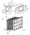
- the cell 10 is normally used in a form called a cell stack 2 including a plurality of stacked cells 10 as shown in FIG.
- the cell stack 2 is configured by sandwiching the sub stack 200 from two end plates 220 from both sides and fastening the end plates 220 on both sides by a fastening mechanism 230.
- FIG. 3 illustrates a cell stack 2 including a plurality of substacks 200.
- a plurality of sub-stacks 200 are stacked in the order of the cell frame 3, the positive electrode 14, the diaphragm 11, and the negative electrode 15 (see the upper diagram of FIG.
- the cell frame 3 includes a bipolar plate 31 disposed between the positive electrode 14 and the negative electrode 15 and a frame body 32 provided around the bipolar plate 31.
- the positive electrode 14 is disposed so as to contact, and on the other surface side of the bipolar plate 31, the negative electrode 15 is disposed so as to contact.
- a bipolar plate 31 is provided inside the frame body 32, and a recess 32 o is formed by the bipolar plate 31 and the frame body 32.
- the concave portions 32o are formed on both sides of the bipolar plate 31, and the positive electrode 14 and the negative electrode 15 are accommodated in the concave portions 32o with the bipolar plate 31 interposed therebetween.
- Each recessed part 32o forms each cell space of the positive electrode cell 12 and the negative electrode cell 13 (refer FIG. 1).
- the bipolar plate 31 is made of, for example, plastic carbon
- the frame body 32 is made of, for example, plastic such as vinyl chloride resin (PVC), polypropylene, polyethylene, fluorine resin, or epoxy resin.
- PVC vinyl chloride resin
- polypropylene polypropylene
- polyethylene polyethylene
- fluorine resin or epoxy resin.
- a frame 32 is integrated around the bipolar plate 31 by injection molding or the like.
- each of the electrodes 14 and 15 is stored in a compressed state in the thickness direction in each of the recesses 32o of the frame body 32.
- the thickness of the electrodes 14 and 15 in a compressed state is determined by the depth of the recess 32o. Is decided.
- An annular seal member 37 such as an O-ring or a flat packing is disposed between the frame bodies 32 of each cell frame 3 in order to suppress leakage of the electrolytic solution.
- the frame body 32 is formed with a seal groove (not shown) for arranging the seal member 37.
- the electrolyte solution in the cell 10 flows through the supply manifolds 33 and 34 and the drainage manifolds 35 and 36 formed through the frame 32 of the cell frame 3 and the supply slits 33 s formed in the frame 32. , 34s and drainage slits 35s, 36s.
- the positive electrode electrolyte is supplied from a liquid supply manifold 33 formed in the lower part of the frame body 32 through a liquid supply slit 33s formed on one surface side of the frame body 32. Are supplied to the positive electrode 14 and discharged to the drainage manifold 35 through the drainage slit 35 s formed in the upper part of the frame 32.
- the negative electrode electrolyte is supplied from the liquid supply manifold 34 formed in the lower part of the frame 32 to the negative electrode 15 through the liquid supply slit 34 s formed on the other surface side of the frame 32, and the frame 32.
- the liquid is discharged to the drainage manifold 36 through the drainage slit 36s formed in the upper part.
- the liquid supply manifolds 33 and 34 and the drainage manifolds 35 and 36 constitute a flow path for the electrolytic solution by stacking the cell frames 3.
- These flow paths communicate with the forward pipes 108 and 109 and the return pipes 110 and 111 of the circulation flow paths 100P and 100N (see FIGS. 1 and 2) via the supply / discharge plate 210 (see the lower figure of FIG. 3), respectively. It is possible to distribute the electrolyte in the cell 10.
- the electrolytic solution is supplied from the lower side of the positive electrode 14 and the negative electrode 15, and the electrolytic solution is discharged from the upper side of the electrodes 14, 15.
- the electrolyte flows from the lower edge of 15 toward the upper edge. 2 and 3, the arrows in the electrodes 14 and 15 indicate the overall flow direction of the electrolytic solution.
- a channel (not shown) having a plurality of grooves through which the electrolytic solution flows may be formed on the surface of the bipolar plate 31 facing the electrodes 14 and 15. Thereby, the flow resistance of the electrolytic solution flowing in the cell 10 can be reduced, and the pressure loss of the electrolytic solution in the cell 10 can be reduced.
- the width and depth of the groove can be appropriately selected according to the size and thickness of the bipolar plate 31 and are not particularly limited.
- the electrodes (positive electrode 14 and negative electrode 15) are formed of a carbon fiber aggregate including a plurality of carbon fibers. Since the electrode of the carbon fiber aggregate is porous and has voids in the electrode, the electrolytic solution flows through the electrode, and the electrolytic solution can permeate and diffuse. Therefore, the reaction area with the electrolytic solution is increased, and it is easy to secure a reaction field.
- Typical examples of the carbon fiber aggregate include carbon felt, carbon cloth, and carbon paper. Among them, since carbon felt and carbon cloth have a relatively high porosity, when used as an electrode material, it is easy to ensure the flowability of the electrolytic solution, and to easily penetrate and diffuse the electrolytic solution into the electrode.
- the carbon felt has an advantage that the electrolyte is easily diffused to every corner of the electrode because the carbon fibers are randomly oriented.
- Typical examples of carbon fibers include PAN-based carbon fibers, pitch-based carbon fibers, and rayon-based carbon fibers.
- One of the features of the electrode of the embodiment is that it has a plurality of ridges 41 on the surface of the carbon fiber 40 constituting the carbon fiber aggregate, as shown in FIG.
- the carbon fiber 40 is a modified cross-section fiber having a plurality of ridges 41 formed on the surface, and has a ridge-like uneven structure on the fiber surface.
- the surface area of the fiber 40 can be increased, the reaction area in contact with the electrolytic solution can be increased, and the reactivity with the electrolytic solution can be improved.
- the circumference ratio L 1 / L 2 is more than 1, the reaction area in contact with the electrolytic solution can be sufficiently secured, and the reactivity with the electrolytic solution is improved.
- the upper limit of L 1 / L 2 is, for example, 2 or less, thereby ensuring a sufficient gap between the ridges 41 and allowing the electrolyte to easily enter the gap between the ridges 41.
- the upper limit of L 1 / L 2 is preferably 1.8 or less, more preferably 1.6 or less, and 1.4 or less.
- a method for obtaining the virtual rectangle R circumscribing the cross section of the carbon fiber 40 will be specifically described.
- the cross section of the electrode is observed with an optical microscope, a scanning electron microscope (SEM), or the like, and the contour of the cross section of the carbon fiber 40 (cross section perpendicular to the longitudinal direction of the fiber) is extracted from the obtained cross-sectional observation image.
- SEM scanning electron microscope
- the outline of the fiber 40 is sandwiched between a pair of parallel lines
- a set of parallel lines where the distance between the parallel lines is the minimum distance
- the outline of the fiber 40 is sandwiched between a pair of parallel lines orthogonal to the pair.
- a set of parallel lines having the maximum distance between the parallel lines is obtained.
- a rectangle surrounded by these two sets of parallel lines is defined as a virtual rectangle R.
- the short side length a of the virtual rectangle R is the short diameter of the carbon fiber 40
- the long side length b is the long diameter of the carbon fiber 40.
- Circumferential length L 1 of the cross section of the carbon fibers 40 can be measured by image analysis of cross-sectional observation images.
- the circumference ratio L 1 / L 2 between the circumference L 1 of the cross section of the carbon fiber 40 and the circumference L 2 of the virtual rectangle R is measured as follows. For a plurality of carbon fibers, the circumference L 1 of each cross section is measured, the virtual rectangle R of each fiber cross section is obtained, and the circumference L 2 of each virtual rectangle R is measured. Then, calculate the L 1 / L 2 of each fiber, and the average value.
- the number of fibers to be measured is, for example, 3 or more, and further 5 or more.
- the carbon fiber 40 preferably satisfies the following requirements.
- S 1 / S 2 is 0.5 or more, it is easy to sufficiently secure the strength of the carbon fiber 40, and the strength reduction of the electrode can be suppressed.
- S 1 / S 2 is larger (closer to 1), the cross-sectional area of the fiber 40 occupying the virtual rectangle R becomes larger, so that it is easier to secure the fiber strength, but there is a concern that the gap between the ridges 41 is narrowed.
- S 1 / S 2 is 0.8 or less, it is easy to ensure a sufficient gap between the ridges 41, and it is difficult for the electrolyte to enter the gap between the ridges 41. Therefore, by S 1 / S 2 is 0.5 to 0.8, while maintaining the fiber strength can be ensured and the reaction area with the electrolyte.
- S 1 / S 2 may be 0.55 or more and 0.75 or less and 0.7 or less.
- Sectional area S 1 of the carbon fibers 40 for example 20 [mu] m 2 or more 320 .mu.m 2 or less, further 30 [mu] m 2 or more 300 [mu] m 2 or less, and it is 90 [mu] m 2 or less.
- Area S 1 of the cross section of the carbon fibers 40 can be measured by image analysis of cross-sectional observation images.
- the area ratio S 1 / S 2 between the area S 1 of the cross section of the carbon fiber 40 and the area S 2 of the virtual rectangle R is measured as follows. For a plurality of carbon fibers, the area S 1 of each cross section is measured, the virtual rectangle R of each fiber cross section is obtained, and the area S 2 of each virtual rectangle R is measured. Then, to calculate the S 1 / S 2 of each fiber, and the average value.
- the number of fibers to be measured is, for example, 3 or more, and further 5 or more.
- the major axis of the carbon fiber 40 is 5 ⁇ m or more and 20 ⁇ m or less.
- the long diameter of the carbon fiber 40 (corresponding to the length b of the long side of the virtual rectangle R) is 5 ⁇ m or more, the strength of the fiber 40 can be easily ensured, and the strength reduction of the electrode can be suppressed.
- the long diameter of the carbon fiber 40 is 20 ⁇ m or less, the fiber is thin and flexible, so that it is difficult to pierce the diaphragm 11 (see the upper drawing of FIG. 3) constituting the cell 10.
- the long diameter of the carbon fiber 40 is 20 ⁇ m or less, the reaction area per unit volume of the electrode increases, and the reaction efficiency with the electrolytic solution increases.
- the major axis of the carbon fiber 40 is further 15 ⁇ m or less.
- the short diameter of the carbon fiber 40 (corresponding to the length a of the short side of the virtual rectangle R) is equal to or less than the long diameter, for example, 2 ⁇ m or more and 15 ⁇ m or less.
- the short diameter and long diameter of the carbon fiber 40 are the lengths a and b of the short side and long side of the virtual rectangle R described above.
- the short diameter and long diameter of the carbon fiber 40 are measured as follows. For a plurality of carbon fibers, the virtual rectangle R of each fiber cross section is obtained, and the short side length a and the long side length b of each virtual rectangle R are measured. Then, the lengths a and b of the short side and long side of each virtual rectangle R are set as the short diameter and long diameter of each fiber, and the respective average values are calculated.
- the number of fibers to be measured is, for example, 3 or more, and further 5 or more.
- the Young's modulus of the carbon fiber 40 is 20 GPa or more and 200 GPa or less.
- the Young's modulus of the carbon fiber 40 is 20 GPa or more, the bending rigidity of the fiber 40 is high, and damage to the electrode can be suppressed when the electrode is compressed and deformed.
- the Young's modulus of the carbon fiber 40 is 200 GPa or less, it is easy to avoid sticking into the diaphragm 11 (see the upper drawing in FIG. 3).
- the Young's modulus of the carbon fiber 40 can be adjusted by, for example, the type of carbon fiber and the firing conditions (such as the firing temperature) for carbonizing the organic fiber as a raw material.
- the Young's modulus of the carbon fiber 40 can be measured by extracting the carbon fiber from the electrode and measuring it by a tensile test.
- the carbon fiber 40 is obtained by baking and carbonizing organic fibers such as PAN fiber, pitch fiber, and rayon fiber.
- the carbon fiber 40 having a plurality of wrinkles 41 on the fiber surface can be produced by firing organic fibers having a modified cross-section with a plurality of wrinkles formed on the surface.
- the organic fiber is a process of extruding a fiber raw material solution from a spinneret (nozzle) into a fiber, and the cross-sectional shape of the fiber can be changed depending on the shape of the nozzle hole.
- organic fiber having a modified cross section it can be produced by forming a plurality of wrinkles on the fiber surface using a nozzle in which a plurality of irregularities are formed in the circumferential direction on the inner peripheral surface of the nozzle hole.
- the electrodes (the positive electrode 14 and the negative electrode 15) according to the embodiment include the following configurations.
- the thickness of the electrode is, for example, from 0.2 mm to 5.0 mm. When the thickness of the electrode is 0.2 mm or more, it is easy to secure a sufficient reaction region (reaction field) with the electrolytic solution. When the thickness of the electrode is 5.0 mm or less, it is easy to sufficiently permeate and diffuse the electrolytic solution throughout the electrode. If the thickness of the electrode is further 2.0 mm or less, the thickness of the cell 10 (see the upper diagram of FIG. 3) can be further reduced.
- the above-mentioned thickness of the electrode is not a thickness in a state where the electrode is incorporated and compressed, but a thickness in an uncompressed state, that is, a natural state where no external force is applied to the electrode.
- the compression ratio of the electrode is, for example, 50% or more and 95% or less.
- the compression ratio of the electrode is 50% or more, the reaction area per unit volume of the electrode increases, and the reaction efficiency with the electrolytic solution increases.
- the compressibility of the electrode is 95% or less, it is easy to secure a void in the electrode and sufficiently ensure the flowability of the electrolytic solution.
- the compression ratio of the electrode is further 60% or more and 85% or less.
- the compression rate of the electrode can be adjusted by, for example, the thickness of the electrode and the depth of the cell space (the recess 32o of the cell frame 3 shown in FIG. 3) that houses the electrode.
- the compression ratio of the electrode can be obtained as ⁇ (T 0 ⁇ T 1 ) / T 0 ) ⁇ ⁇ 100 (%), where T 1 is the thickness of the compressed state of the electrode and T 0 is the thickness of the uncompressed state. it can.
- the electrodes (the positive electrode 14 and the negative electrode 15) according to the embodiment are formed of carbon fiber aggregates, and have a plurality of ridges 41 on the surface of the carbon fibers 40 constituting the carbon fiber aggregates.
- the reaction area in contact with the electrolyte increases and the reactivity with the electrolyte can be improved.
- the ratio L 1 / L 2 between the circumferential length (L 1 ) of the cross section of the carbon fiber 40 and the circumferential length (L 2 ) of the virtual rectangle R circumscribing the cross section of the carbon fiber 40 is more than 1, so that The reaction area in contact with the liquid can be sufficiently secured, and the reactivity with the electrolytic solution is improved. Therefore, according to the electrode of the embodiment, the reaction resistance of the electrode can be reduced, and the battery performance can be improved.
- the cell 10 according to the embodiment can reduce the reaction resistance of the electrode by providing the electrode of the above-described embodiment, and can improve battery performance.
- the RF battery 1 according to the embodiment includes the cell 10 according to the embodiment described above, the reaction resistance of the electrode can be reduced and the battery performance can be improved, and thus the battery performance is excellent.
- Test Example 1 A carbon fiber assembly made of carbon fibers having different cross-sectional shapes was prepared, and a single-cell RF battery was assembled by using this as an electrode, and the evaluation was performed.
- Test Example 1 an organic fiber having a modified cross-section with a plurality of wrinkles formed on the surface is used as a raw material, and various carbon fiber assemblies (carbon felt) obtained by processing this into a felt shape and firing are used as an electrode.
- Single cells (sample Nos. 1 to 4) were produced.
- Sample No. The carbon fibers constituting the electrodes used in the single cells 1 to 4 have a plurality of wrinkles on the fiber surface.
- the carbon fiber was extracted from each electrode, the tensile test was performed, and the Young's modulus of the carbon fiber was measured. The Young's modulus was in the range of 30 GPa to 150 GPa.
- a carbon felt obtained by processing and firing organic fibers having a circular cross section into a felt shape was prepared, and a single cell (sample No. 10) was produced using this as an electrode.
- Sample No. 10 The Young's modulus of the carbon fiber constituting the electrode used for 10 single cells was about 300 GPa.
- a carbon felt electrode made of the same carbon fiber was used for each positive and negative electrode, and the area of each electrode was 9 cm 2 .
- the thickness and compression rate of the electrodes used in the single cell of each sample were set to be approximately the same, and the thickness was 2.0 mm and the compression rate was 60%.
- ⁇ Perimeter ratio / area ratio / cross-sectional area of carbon fiber> The cross section of the electrode of each sample is observed with an SEM, the circumference L 1 of the cross section of the three carbon fibers is measured by image analysis, and the circumference L 2 of the virtual rectangle R of each fiber cross section is measured. The average value of the circumferential length ratio L 1 / L 2 of the carbon fibers constituting the carbon fiber was calculated. Further, for the same three carbon fibers, the area S 1 of the cross section is measured, and the area S 2 of the virtual rectangle R of each fiber cross section is measured to determine the area ratio S 1 / S 2 of the carbon fibers constituting the electrode. The average value of was calculated.
- Table 1 shows the circumferential length ratio L 1 / L 2 ⁇ area ratio S 1 / S 2 ⁇ cross-sectional area S 1 of the carbon fibers constituting the electrode in each sample.
- ⁇ Charge / discharge test> A single cell RF battery was assembled using a single cell of each sample, and a charge / discharge test was performed. A vanadium sulfate aqueous solution (vanadium concentration: 1.7 mol / L) was used for each positive and negative electrolyte. The charge / discharge test was performed at a constant current of a current density of 70 mA / cm 2 , and charging and discharging were switched when a predetermined switching voltage set in advance was reached. And the cell resistance at the time of 3 cycles charging / discharging was calculated
- reaction resistance of the electrode was obtained from the cell resistance obtained from the single cell battery of each sample.
- the reaction resistance is a resistance obtained by subtracting the conductive resistance from the cell resistance, and is calculated by the following equation.
- the sample No. 1 in which the circumferential length ratio L 1 / L 2 of the carbon fibers constituting the electrode is more than one. 1-4 are sample Nos. It can be seen that the reaction resistance is small compared to 10, and the reaction resistance of the electrode can be reduced. Therefore, when the circumferential length ratio L 1 / L 2 of the carbon fiber is more than 1, the reaction resistance of the electrode can be reduced, and the battery performance of the RF battery can be improved.
- Redox flow battery (RF battery) 2 Cell stack 10 Redox flow battery cell (cell) DESCRIPTION OF SYMBOLS 11 Diaphragm 12 Positive electrode cell 13 Negative electrode 14 Positive electrode 15 Negative electrode 3 Cell frame 31 Bipolar plate 32 Frame 32o Recess 33, 34 Supply manifold 35, 36 Drain manifold 33s, 34s Supply slit 35s, 36s Drain slit 37 Seal member 40 Carbon fiber 41 ⁇ R Virtual rectangle 100P Positive electrode circulation channel 100N Negative electrode circulation channel 106 Positive electrode electrolyte tank 107 Negative electrode electrolyte tank 108, 109 Outward piping 110, 111 Return piping 112, 113 Pump 200 Substack 210 Supply / Exhaust Plate 220 End plate 230 Tightening mechanism C AC / DC converter P Power system
Landscapes
- Chemical & Material Sciences (AREA)
- Chemical Kinetics & Catalysis (AREA)
- Electrochemistry (AREA)
- General Chemical & Material Sciences (AREA)
- Engineering & Computer Science (AREA)
- Manufacturing & Machinery (AREA)
- Life Sciences & Earth Sciences (AREA)
- Sustainable Development (AREA)
- Sustainable Energy (AREA)
- Inert Electrodes (AREA)
- Fuel Cell (AREA)
Abstract
Description
複数の炭素繊維を含む炭素繊維集合体で形成されたレドックスフロー電池用電極であって、
前記炭素繊維は表面に複数の襞を有し、
前記炭素繊維の断面の周長をL1、前記炭素繊維の断面に外接する仮想矩形の周長をL2とするとき、L1とL2との比L1/L2が1超である。 The electrode for the redox flow battery of the present disclosure is:
An electrode for a redox flow battery formed of a carbon fiber assembly including a plurality of carbon fibers,
The carbon fiber has a plurality of wrinkles on the surface,
L 1 the peripheral length of the cross section of the carbon fibers, when the circumferential length of a virtual rectangle circumscribing the cross-section of the carbon fiber and L 2, L 1 and a ratio L 1 / L 2 and L 2 is 1 greater .
上記本開示のレドクスフロー電池用電極を備える。 The redox flow battery cell of the present disclosure is
The redox flow battery electrode of the present disclosure is provided.
上記本開示のレドックスフロー電池セルを備える。 The redox flow battery of the present disclosure is
The redox flow battery cell of the present disclosure is provided.
レドックスフロー電池の更なる電池性能の向上が望まれている。 [Problems to be solved by the present disclosure]
It is desired to further improve the battery performance of the redox flow battery.
本開示によれば、電極の反応抵抗を低減できるレドックスフロー電池用電極を提供できる。また、本開示によれば、電池性能に優れるレドックスフロー電池セル及びレドックスフロー電池を提供できる。 [Effects of the present disclosure]
According to the present disclosure, it is possible to provide a redox flow battery electrode capable of reducing the reaction resistance of the electrode. Moreover, according to this indication, the redox flow battery cell and redox flow battery which are excellent in battery performance can be provided.
本発明者らは、炭素繊維集合体の電極を構成する炭素繊維として、繊維表面に複数の襞を有する異形断面繊維を用いることを提案する。これにより、繊維の比表面積を大きくして、電解液と接する反応面積を増やすことができ、電解液との反応性を向上させることができる。よって、電極の反応抵抗を低減でき、電池性能を向上できる。 [Description of Embodiment of Present Invention]
The present inventors propose to use a modified cross-section fiber having a plurality of wrinkles on the fiber surface as the carbon fiber constituting the electrode of the carbon fiber assembly. Thereby, the specific surface area of a fiber can be enlarged, the reaction area which contacts electrolyte solution can be increased, and the reactivity with electrolyte solution can be improved. Therefore, the reaction resistance of the electrode can be reduced, and the battery performance can be improved.
(1)実施形態に係るレドックスフロー電池用電極は、
複数の炭素繊維を含む炭素繊維集合体で形成されたレドックスフロー電池用電極であって、
前記炭素繊維は表面に複数の襞を有し、
前記炭素繊維の断面の周長をL1、前記炭素繊維の断面に外接する仮想矩形の周長をL2とするとき、L1とL2との比L1/L2が1超である。 First, the contents of the embodiments of the present invention will be listed and described.
(1) The electrode for a redox flow battery according to the embodiment is
An electrode for a redox flow battery formed of a carbon fiber assembly including a plurality of carbon fibers,
The carbon fiber has a plurality of wrinkles on the surface,
L 1 the peripheral length of the cross section of the carbon fibers, when the circumferential length of a virtual rectangle circumscribing the cross-section of the carbon fiber and L 2, L 1 and a ratio L 1 / L 2 and L 2 is 1 greater .
上記(1)から(5)のいずれか1つに記載のレドックスフロー電池用電極を備える。 (6) The redox flow battery cell according to the embodiment is
The redox flow battery electrode according to any one of (1) to (5) above is provided.
上記(6)に記載のレドックスフロー電池セルを備える。 (7) The redox flow battery according to the embodiment is
The redox flow battery cell according to (6) above is provided.
本願発明の実施形態に係るレドックスフロー電池用電極(以下、単に「電極」と呼ぶ場合がある)、レドックスフロー電池セル(以下、単に「セル」と呼ぶ場合がある)、及びレドックスフロー電池(RF電池)の具体例を、以下に図面を参照しつつ説明する。図中の同一符号は同一又は相当部分を示す。なお、本願発明はこれらの例示に限定されるものではなく、請求の範囲によって示され、請求の範囲と均等の意味および範囲内でのすべての変更が含まれることが意図される。 [Details of the embodiment of the present invention]
An electrode for a redox flow battery (hereinafter sometimes simply referred to as “electrode”), a redox flow battery cell (hereinafter sometimes simply referred to as “cell”), and a redox flow battery (RF) according to an embodiment of the present invention A specific example of the battery will be described below with reference to the drawings. The same reference numerals in the drawings indicate the same or corresponding parts. In addition, this invention is not limited to these illustrations, is shown by the claim, and intends that all the changes within the meaning and range equivalent to a claim are included.
初めに、図1~図3を参照して、実施形態に係るRF電池1、及びRF電池1に備えるセル10の一例を説明する。図1、図2に示すRF電池1は、正極電解液及び負極電解液に酸化還元により価数が変化する金属イオンを活物質として含有する電解液を使用し、正極電解液に含まれるイオンの酸化還元電位と、負極電解液に含まれるイオンの酸化還元電位との差を利用して充放電を行う電池である。ここでは、RF電池1の一例として、正極電解液及び負極電解液にVイオンを含有するバナジウム電解液を使用したバナジウム系RF電池を示す。図1中のセル10内の実線矢印は充電反応を、破線矢印は放電反応をそれぞれ示している。RF電池1は、交流/直流変換器Cを介して電力系統Pに接続され、例えば、負荷平準化用途、瞬低補償や非常用電源などの用途、太陽光発電や風力発電といった自然エネルギー発電の出力平滑化用途に利用される。 << RF battery >>
First, an example of the
セル10は、図1に示すように、正極電極14と、負極電極15と、両電極14、15間に介在される隔膜11とを有する。セル10の構造は、隔膜11を挟んで正極セル12と負極セル13とに分離され、正極セル12に正極電極14、負極セル13に負極電極15が内蔵されている。 "cell"
As shown in FIG. 1, the
セル10は、単数のセル10を備える単セルで構成されていてもよいし、複数のセル10を備える多セルで構成されていてもよい。セル10は通常、図2に示すような、セル10を複数積層して備えるセルスタック2と呼ばれる形態で利用される。セルスタック2は、図3の下図に示すように、サブスタック200をその両側から2枚のエンドプレート220で挟み込み、両側のエンドプレート220を締付機構230で締め付けることで構成されている。図3では、複数のサブスタック200を備えるセルスタック2を例示している。サブスタック200は、セルフレーム3、正極電極14、隔膜11、負極電極15の順に複数積層され(図3の上図参照)、その積層体の両端に給排板210(図3の下図参照、図2では図示略)が配置された構造である。給排板210には、各循環流路100P、100N(図1、図2参照)の往路配管108、109及び復路配管110、111が接続される。 Cell stack
The
セルフレーム3は、図3の上図に示すように、正極電極14と負極電極15との間に配置される双極板31と、双極板31の周囲に設けられる枠体32とを有する。双極板31の一面側には、正極電極14が接触するように配置され、双極板31の他面側には、負極電極15が接触するように配置される。枠体32の内側には、双極板31が設けられ、双極板31と枠体32により凹部32oが形成される。凹部32oは、双極板31の両側にそれぞれ形成され、各凹部32o内に正極電極14及び負極電極15が双極板31を挟んで収納される。各凹部32oは、正極セル12及び負極セル13(図1参照)の各セル空間を形成する。 (Cell frame)
As shown in the upper diagram of FIG. 3, the
双極板31の各電極14、15に対向する面には、電解液が流通する複数の溝部を有する流路(図示せず)が形成されていてもよい。これにより、セル10内を流れる電解液の流通抵抗を小さくでき、セル10での電解液の圧力損失を低減できる。溝部の幅や深さは、双極板31のサイズや厚さなどに応じて適宜選択することができ、特に限定されない。 (Bipolar plate)
A channel (not shown) having a plurality of grooves through which the electrolytic solution flows may be formed on the surface of the
実施形態に係る電極(正極電極14及び負極電極15)は、複数の炭素繊維を含む炭素繊維集合体で形成されている。炭素繊維集合体の電極は多孔質であり、電極内に空隙を有しているため、電極内に電解液が流通し、電解液を浸透・拡散させることができる。よって、電解液との反応領域が増え、反応場を確保し易い。炭素繊維集合体としては、代表的には、カーボンフェルト、カーボンクロス、カーボンペーパーが挙げられる。中でも、カーボンフェルト、カーボンクロスは、空隙率が比較的高いため、電極材料に用いた場合、電解液の流通性を確保し易く、電極内に電解液を浸透・拡散させ易い。特に、カーボンフェルトは、炭素繊維がランダムに配向しているため、電極内の隅々まで電解液を拡散させ易いなどの利点がある。炭素繊維としては、代表的には、PAN系炭素繊維、ピッチ系炭素繊維、レーヨン系炭素繊維が挙げられる。 (electrode)
The electrodes (
炭素繊維40は、表面に複数の襞41が形成された異形断面繊維であり、繊維表面に襞状の凹凸構造を有する。炭素繊維40の表面に複数の襞41を有することで、繊維40の表面積を大きくして、電解液と接する反応面積を増やし、電解液との反応性を改善できる。 (Carbon fiber)
The
炭素繊維40の断面の周長をL1、炭素繊維40の断面に外接する仮想矩形Rの周長をL2とするとき、L1とL2との比L1/L2が1超である。
周長比L1/L2が1超であることで、電解液と接する反応面積を十分に確保でき、電解液との反応性が向上する。炭素繊維40の表面積は周長L1に比例することから、L1/L2が大きいほど、比表面積が大きく、電解液との反応面積が増えることになる。よって、L1/L2は1.1以上であることが好ましい。但し、L1/L2が大き過ぎる場合、襞41の数が多くなり、襞41同士がひっついたり、襞41間の隙間が狭くなったりする懸念がある。そのため、襞41間の隙間に電解液が入り込み難くなり、電解液との反応面積を増やす効果が得られ難くなる虞がある。L1/L2の上限は、例えば2以下であり、これにより、襞41間に十分な隙間を確保して、襞41間の隙間に電解液が浸入し易くなる。L1/L2の上限は、好ましくは1.8以下、更に1.6以下、1.4以下である。 <
The circumferential length of the cross-section of the
When the circumference ratio L 1 / L 2 is more than 1, the reaction area in contact with the electrolytic solution can be sufficiently secured, and the reactivity with the electrolytic solution is improved. The surface area of the
炭素繊維40の断面の面積をS1、炭素繊維40の断面に外接する仮想矩形Rの面積をS2とするとき、S1とS2との比S1/S2が0.5以上0.8以下である。
面積比S1/S2が0.5以上であることで、炭素繊維40の強度を十分に確保し易く、電極の強度低下を抑制できる。S1/S2が大きい(1に近い)ほど、仮想矩形Rに占める繊維40の断面積が大きくなるため、繊維強度を確保し易くなるが、襞41間の隙間が狭くなる懸念がある。そのため、襞41間の隙間に電解液が入り込み難くなり、電解液との反応面積を増やす効果が得られ難くなる虞がある。S1/S2が0.8以下であることで、襞41間の隙間を十分に確保し易く、襞41間の隙間への電解液の浸入が阻害され難くなる。よって、S1/S2が0.5以上0.8以下であることで、繊維強度を確保しつつ、電解液との反応面積を確保できる。S1/S2は、更に0.55以上0.75以下、0.7以下であることが挙げられる。炭素繊維40の断面積S1は、例えば20μm2以上320μm2以下、更に30μm2以上300μm2以下、90μm2以下であることが挙げられる。 <
S 1 and the area of the cross section of the
When the area ratio S 1 / S 2 is 0.5 or more, it is easy to sufficiently secure the strength of the
炭素繊維40の長径が5μm以上20μm以下である。
炭素繊維40の長径(仮想矩形Rの長辺の長さbに相当)が5μm以上であることで、繊維40の強度を確保し易く、電極の強度低下を抑制できる。炭素繊維40の長径が20μm以下であることで、繊維が細く、可撓性を有することにより、セル10を構成する隔膜11(図3上図参照)に突き刺さり難い。また、炭素繊維40の長径が20μm以下の場合、電極の単位体積あたりの反応面積が増え、電解液との反応効率が高くなる。炭素繊維40の長径は、更に15μm以下であることが挙げられる。炭素繊維40の短径(仮想矩形Rの短辺の長さaに相当)は、長径と同等以下であり、例えば2μm以上15μm以下であることが挙げられる。 <Fiber major axis>
The major axis of the
When the long diameter of the carbon fiber 40 (corresponding to the length b of the long side of the virtual rectangle R) is 5 μm or more, the strength of the
炭素繊維40のヤング率が20GPa以上200GPa以下である。
炭素繊維40のヤング率が20GPa以上であることで、繊維40の曲げ剛性が高く、電極を圧縮変形させたときに、電極の損傷を抑制できる。炭素繊維40のヤング率が200GPa以下であることで、隔膜11(図3上図参照)への突き刺さりを回避し易い。炭素繊維40のヤング率は、例えば、炭素繊維の種類や、原料となる有機繊維を炭素化する焼成条件(焼成温度など)により調整可能である。 <Young's modulus of fiber>
The Young's modulus of the
When the Young's modulus of the
炭素繊維40は、PAN繊維、ピッチ繊維、レーヨン繊維などの有機繊維を焼成して炭素化することによって得られる。繊維表面に複数の襞41を有する炭素繊維40は、表面に複数の襞が形成された異形断面の有機繊維を焼成することで作製できる。有機繊維は、繊維の原料溶液を紡糸口金(ノズル)から押し出して繊維にする工程で、ノズル孔の形状によって繊維の断面形状を変えることが可能である。上述した異形断面の有機繊維の場合、ノズル孔の内周面に複数の凹凸が周方向に形成されたノズルを用いて繊維表面に複数の襞を形成することによって作製することが可能である。 <Fabrication>
The
電極の厚さは、例えば0.2mm以上5.0mm以下であることが挙げられる。電極の厚さが0.2mm以上であることで、電解液との反応領域(反応場)を十分に確保し易い。電極の厚さが5.0mm以下であることで、電極内全体に電解液を十分に浸透・拡散させ易い。電極の厚さが更に2.0mm以下であれば、セル10(図3上図参照)の厚みをより薄くできる。 (Electrode thickness)
The thickness of the electrode is, for example, from 0.2 mm to 5.0 mm. When the thickness of the electrode is 0.2 mm or more, it is easy to secure a sufficient reaction region (reaction field) with the electrolytic solution. When the thickness of the electrode is 5.0 mm or less, it is easy to sufficiently permeate and diffuse the electrolytic solution throughout the electrode. If the thickness of the electrode is further 2.0 mm or less, the thickness of the cell 10 (see the upper diagram of FIG. 3) can be further reduced.
電極の圧縮率は、例えば50%以上95%以下であることが挙げられる。電極の圧縮率が50%以上であることで、電極の単位体積あたりの反応面積が増え、電解液との反応効率が高くなる。電極の圧縮率が95%以下であることで、電極内の空隙を確保して、電解液の流通性を十分に確保し易い。また、電極の圧縮率が95%以下の場合、過度の変形による電極の損傷を抑制できる。電極の圧縮率は、更に60%以上85%以下であることが挙げられる。電極の圧縮率は、例えば、電極の厚さや、電極を収納するセル空間(図3に示すセルフレーム3の凹部32o)の深さにより調整可能である。 (Electrode compression rate)
The compression ratio of the electrode is, for example, 50% or more and 95% or less. When the compression ratio of the electrode is 50% or more, the reaction area per unit volume of the electrode increases, and the reaction efficiency with the electrolytic solution increases. When the compressibility of the electrode is 95% or less, it is easy to secure a void in the electrode and sufficiently ensure the flowability of the electrolytic solution. Moreover, when the compression ratio of the electrode is 95% or less, damage to the electrode due to excessive deformation can be suppressed. The compression ratio of the electrode is further 60% or more and 85% or less. The compression rate of the electrode can be adjusted by, for example, the thickness of the electrode and the depth of the cell space (the recess 32o of the
実施形態に係る電極(正極電極14及び負極電極15)は、炭素繊維集合体で形成されており、炭素繊維集合体を構成する炭素繊維40の表面に複数の襞41を有することで、電解液と接する反応面積が増え、電解液との反応性を改善できる。そして、炭素繊維40の断面の周長(L1)と炭素繊維40の断面に外接する仮想矩形Rの周長(L2)との比L1/L2が1超であることで、電解液と接する反応面積を十分に確保でき、電解液との反応性が向上する。したがって、実施形態の電極によれば、電極の反応抵抗を低減でき、電池性能を向上できる。 [Effect of the embodiment]
The electrodes (the
断面形状が異なる炭素繊維からなる炭素繊維集合体を用意し、これを電極に用いて単セルのRF電池を組み立て、その評価を行った。 [Test Example 1]
A carbon fiber assembly made of carbon fibers having different cross-sectional shapes was prepared, and a single-cell RF battery was assembled by using this as an electrode, and the evaluation was performed.
各試料の電極の断面をSEMで観察し、画像解析により3本の炭素繊維の断面の周長L1を計測すると共に、各繊維断面の仮想矩形Rの周長L2を計測して、電極を構成する炭素繊維の周長比L1/L2の平均値を算出して求めた。また、同じ3本の炭素繊維について、断面の面積S1を計測すると共に、各繊維断面の仮想矩形Rの面積S2を計測して、電極を構成する炭素繊維の面積比S1/S2の平均値を算出して求めた。また、炭素繊維の断面積S1の平均値を算出して求めた。各試料における電極を構成する炭素繊維の周長比L1/L2・面積比S1/S2・断面積S1を表1に示す。 <Perimeter ratio / area ratio / cross-sectional area of carbon fiber>
The cross section of the electrode of each sample is observed with an SEM, the circumference L 1 of the cross section of the three carbon fibers is measured by image analysis, and the circumference L 2 of the virtual rectangle R of each fiber cross section is measured. The average value of the circumferential length ratio L 1 / L 2 of the carbon fibers constituting the carbon fiber was calculated. Further, for the same three carbon fibers, the area S 1 of the cross section is measured, and the area S 2 of the virtual rectangle R of each fiber cross section is measured to determine the area ratio S 1 / S 2 of the carbon fibers constituting the electrode. The average value of was calculated. Moreover, it was determined by calculating the average value of the cross-sectional area S 1 of the carbon fibers. Table 1 shows the circumferential length ratio L 1 / L 2 · area ratio S 1 / S 2 · cross-sectional area S 1 of the carbon fibers constituting the electrode in each sample.
上述した各繊維断面の仮想矩形Rの長辺の長さbを計測し、その平均値を算出して、電極を構成する炭素繊維の長径を求めた。各試料における電極を構成する炭素繊維の長径を表1に示す。 <Longer diameter of carbon fiber>
The length b of the long side of the virtual rectangle R of each fiber cross section described above was measured, the average value thereof was calculated, and the long diameter of the carbon fiber constituting the electrode was obtained. Table 1 shows the major axis of the carbon fiber constituting the electrode in each sample.
各試料の単セルを用いて単セルのRF電池を組み立て、充放電試験を行った。正負の各電解液には、硫酸バナジウム水溶液(バナジウム濃度:1.7mol/L)を用いた。充放電試験は、電流密度70mA/cm2の定電流で行い、予め設定した所定の切り替え電圧に達したら、充電と放電とを切り替えた。そして、3サイクル充放電時のセル抵抗を求めた。セル抵抗は、充放電時の充電の中間電圧と放電の中間電圧との差を2で割り、その値を更に電流値で割った抵抗値に電極面積を掛けることにより算出するものとする。「中間電圧」とは、充電又は放電を開始してから終了するまでの時間の中間時点における電圧値をいう。 <Charge / discharge test>
A single cell RF battery was assembled using a single cell of each sample, and a charge / discharge test was performed. A vanadium sulfate aqueous solution (vanadium concentration: 1.7 mol / L) was used for each positive and negative electrolyte. The charge / discharge test was performed at a constant current of a current density of 70 mA / cm 2 , and charging and discharging were switched when a predetermined switching voltage set in advance was reached. And the cell resistance at the time of 3 cycles charging / discharging was calculated | required. The cell resistance is calculated by dividing the difference between the charging intermediate voltage and the discharging intermediate voltage by 2 and dividing the value by the current value and multiplying the resistance value by the electrode area. “Intermediate voltage” refers to a voltage value at an intermediate point in time from the start to the end of charging or discharging.
各試料の単セル電池で求めたセル抵抗から電極の反応抵抗を求めた。反応抵抗は、セル抵抗から導電抵抗を差し引いた抵抗とし、下記の式により算出するものとする。導電抵抗はバッテリーハイテスタで測定して求めた。各試料における電極の反応抵抗を表1に示す。
反応抵抗(Ω・cm2)=セル抵抗(Ω・cm2)-導電抵抗(Ω・cm2) <Reaction resistance of electrode>
The reaction resistance of the electrode was obtained from the cell resistance obtained from the single cell battery of each sample. The reaction resistance is a resistance obtained by subtracting the conductive resistance from the cell resistance, and is calculated by the following equation. The conductive resistance was obtained by measuring with a battery high tester. Table 1 shows the reaction resistance of the electrode in each sample.
Reaction resistance (Ω · cm 2 ) = cell resistance (Ω · cm 2 ) −conductive resistance (Ω · cm 2 )

2 セルスタック
10 レドックスフロー電池セル(セル)
11 隔膜
12 正極セル 13 負極セル
14 正極電極 15 負極電極
3 セルフレーム
31 双極板 32 枠体
32o 凹部
33、34 給液マニホールド 35、36 排液マニホールド
33s、34s 給液スリット 35s、36s 排液スリット
37 シール部材
40 炭素繊維 41 襞
R 仮想矩形
100P 正極循環流路 100N 負極循環流路
106 正極電解液タンク 107 負極電解液タンク
108、109 往路配管 110、111 復路配管
112、113 ポンプ
200 サブスタック
210 給排板 220 エンドプレート 230 締付機構
C 交流/直流変換器 P 電力系統 1 Redox flow battery (RF battery)
2
DESCRIPTION OF
Claims (7)
- 複数の炭素繊維を含む炭素繊維集合体で形成されたレドックスフロー電池用電極であって、
前記炭素繊維は表面に複数の襞を有し、
前記炭素繊維の断面の周長をL1、前記炭素繊維の断面に外接する仮想矩形の周長をL2とするとき、L1とL2との比L1/L2が1超であるレドックスフロー電池用電極。 An electrode for a redox flow battery formed of a carbon fiber assembly including a plurality of carbon fibers,
The carbon fiber has a plurality of wrinkles on the surface,
L 1 the peripheral length of the cross section of the carbon fibers, when the circumferential length of a virtual rectangle circumscribing the cross-section of the carbon fiber and L 2, L 1 and a ratio L 1 / L 2 and L 2 is 1 greater Redox flow battery electrode. - 前記炭素繊維の断面の面積をS1、前記炭素繊維の断面に外接する仮想矩形の面積をS2とするとき、S1とS2との比S1/S2が0.5以上0.8以下である請求項1に記載のレドックスフロー電池用電極。 Wherein S 1 the area of the cross section of the carbon fiber, the area of the virtual rectangle circumscribing the cross-section of the carbon fiber when the S 2, S 1 and a ratio S 1 / S 2 of S 2 is 0.5 or more 0. The electrode for a redox flow battery according to claim 1, which is 8 or less.
- 前記炭素繊維の長径が5μm以上20μm以下である請求項1又は請求項2に記載のレドックスフロー電池用電極。 The electrode for a redox flow battery according to claim 1 or 2, wherein a major axis of the carbon fiber is 5 µm or more and 20 µm or less.
- 前記炭素繊維のヤング率が20GPa以上200GPa以下である請求項1から請求項3のいずれか1項に記載のレドックスフロー電池用電極。 The redox flow battery electrode according to any one of claims 1 to 3, wherein the Young's modulus of the carbon fiber is 20 GPa or more and 200 GPa or less.
- 前記炭素繊維集合体がカーボンフェルト又はカーボンクロスである請求項1から請求項4のいずれか1項に記載のレドックスフロー電池用電極。 The electrode for a redox flow battery according to any one of claims 1 to 4, wherein the carbon fiber aggregate is carbon felt or carbon cloth.
- 請求項1から請求項5のいずれか1項に記載のレドックスフロー電池用電極を備えるレドックスフロー電池セル。 A redox flow battery cell comprising the redox flow battery electrode according to any one of claims 1 to 5.
- 請求項6に記載のレドックスフロー電池セルを備えるレドックスフロー電池。 A redox flow battery comprising the redox flow battery cell according to claim 6.
Priority Applications (8)
| Application Number | Priority Date | Filing Date | Title |
|---|---|---|---|
| PCT/JP2018/008167 WO2019167283A1 (en) | 2018-03-02 | 2018-03-02 | Electrode for redox-flow batteries, redox-flow battery cell, and redox-flow battery |
| CN201880002170.XA CN110447139B (en) | 2018-03-02 | 2018-03-02 | Electrode for redox flow battery, redox flow battery cell, and redox flow battery |
| US16/305,454 US10714760B2 (en) | 2018-03-02 | 2018-03-02 | Electrode for redox flow batteries, redox flow battery cell, and redox flow battery |
| KR1020187033876A KR102431061B1 (en) | 2018-03-02 | 2018-03-02 | Electrode for redox flow battery, redox flow battery cell and redox flow battery |
| JP2018549584A JP6970388B2 (en) | 2018-03-02 | 2018-03-02 | Redox flow battery electrodes, redox flow battery cells and redox flow batteries |
| AU2018260798A AU2018260798B2 (en) | 2018-03-02 | 2018-03-02 | Electrode for redox flow batteries, redox flow battery cell, and redox flow battery |
| EP18792343.8A EP3761423A4 (en) | 2018-03-02 | 2018-03-02 | Electrode for redox-flow batteries, redox-flow battery cell, and redox-flow battery |
| TW107141008A TWI750427B (en) | 2018-03-02 | 2018-11-19 | Electrode for redox flow batteries, redox flow battery cell, and redox flow battery |
Applications Claiming Priority (1)
| Application Number | Priority Date | Filing Date | Title |
|---|---|---|---|
| PCT/JP2018/008167 WO2019167283A1 (en) | 2018-03-02 | 2018-03-02 | Electrode for redox-flow batteries, redox-flow battery cell, and redox-flow battery |
Publications (1)
| Publication Number | Publication Date |
|---|---|
| WO2019167283A1 true WO2019167283A1 (en) | 2019-09-06 |
Family
ID=67767468
Family Applications (1)
| Application Number | Title | Priority Date | Filing Date |
|---|---|---|---|
| PCT/JP2018/008167 WO2019167283A1 (en) | 2018-03-02 | 2018-03-02 | Electrode for redox-flow batteries, redox-flow battery cell, and redox-flow battery |
Country Status (8)
| Country | Link |
|---|---|
| US (1) | US10714760B2 (en) |
| EP (1) | EP3761423A4 (en) |
| JP (1) | JP6970388B2 (en) |
| KR (1) | KR102431061B1 (en) |
| CN (1) | CN110447139B (en) |
| AU (1) | AU2018260798B2 (en) |
| TW (1) | TWI750427B (en) |
| WO (1) | WO2019167283A1 (en) |
Cited By (1)
| Publication number | Priority date | Publication date | Assignee | Title |
|---|---|---|---|---|
| WO2024075439A1 (en) * | 2022-10-06 | 2024-04-11 | 住友電気工業株式会社 | Redox flow battery electrode, redox flow battery cell, and redox flow battery system |
Families Citing this family (2)
| Publication number | Priority date | Publication date | Assignee | Title |
|---|---|---|---|---|
| JP7232431B2 (en) * | 2019-10-09 | 2023-03-03 | 住友電気工業株式会社 | Electrodes, battery cells, cell stacks, and redox flow battery systems |
| WO2022000364A1 (en) * | 2020-07-01 | 2022-01-06 | 东莞理工学院 | Biomembrane electrode material based on special-shaped carbon fiber, and preparation method therefor and use thereof |
Citations (7)
| Publication number | Priority date | Publication date | Assignee | Title |
|---|---|---|---|---|
| JPH08287923A (en) | 1995-04-13 | 1996-11-01 | Toyobo Co Ltd | Electrode material for flowing liquid electrolytic cell |
| JP2001085025A (en) | 1999-09-10 | 2001-03-30 | Toyobo Co Ltd | Carbon electrode material assembly |
| JP2004200153A (en) * | 2002-12-02 | 2004-07-15 | Sanyo Electric Co Ltd | Fuel cell and material for fuel cell gas diffusion layer |
| JP2006004709A (en) * | 2004-06-16 | 2006-01-05 | Nissan Motor Co Ltd | Solid polymer electrolyte fuel cell |
| JP2013232434A (en) | 2013-07-11 | 2013-11-14 | Sumitomo Electric Ind Ltd | Electrolytic solution for redox flow battery, redox flow battery, and method for operating redox flow battery |
| JP2015190066A (en) | 2014-03-27 | 2015-11-02 | 東邦テナックス株式会社 | Carbon fiber felt, manufacturing method thereof, and liquid circulation type electrolytic cell |
| JP2017171511A (en) * | 2016-03-18 | 2017-09-28 | 住友電気工業株式会社 | Method for producing carbon material |
Family Cites Families (8)
| Publication number | Priority date | Publication date | Assignee | Title |
|---|---|---|---|---|
| JPS6197422A (en) * | 1984-10-16 | 1986-05-15 | Nikkiso Co Ltd | High-strength carbon fiber and its production |
| US6503856B1 (en) * | 2000-12-05 | 2003-01-07 | Hexcel Corporation | Carbon fiber sheet materials and methods of making and using the same |
| US8822057B2 (en) * | 2011-10-17 | 2014-09-02 | Lockheed Martin Corporation | High surface area flow battery electrodes |
| WO2014012649A1 (en) * | 2012-07-20 | 2014-01-23 | Carl Freudenberg Kg | Electrically conductive sheet material |
| JP2016160560A (en) * | 2015-03-04 | 2016-09-05 | 三菱レイヨン株式会社 | Method for manufacturing carbon fiber bundle |
| WO2017068944A1 (en) * | 2015-10-22 | 2017-04-27 | 住友電気工業株式会社 | Redox flow battery electrode, and redox flow battery |
| WO2017175262A1 (en) * | 2016-04-04 | 2017-10-12 | テックワン株式会社 | Carbon fiber, carbon fiber material production method, electrical device, and rechargeable battery |
| JP6819701B2 (en) * | 2017-02-16 | 2021-01-27 | 三菱ケミカル株式会社 | Carbon fiber precursor Acrylic fiber, carbon fiber and their manufacturing method |
-
2018
- 2018-03-02 KR KR1020187033876A patent/KR102431061B1/en active IP Right Grant
- 2018-03-02 EP EP18792343.8A patent/EP3761423A4/en active Pending
- 2018-03-02 CN CN201880002170.XA patent/CN110447139B/en active Active
- 2018-03-02 WO PCT/JP2018/008167 patent/WO2019167283A1/en active Application Filing
- 2018-03-02 AU AU2018260798A patent/AU2018260798B2/en active Active
- 2018-03-02 US US16/305,454 patent/US10714760B2/en active Active
- 2018-03-02 JP JP2018549584A patent/JP6970388B2/en active Active
- 2018-11-19 TW TW107141008A patent/TWI750427B/en active
Patent Citations (7)
| Publication number | Priority date | Publication date | Assignee | Title |
|---|---|---|---|---|
| JPH08287923A (en) | 1995-04-13 | 1996-11-01 | Toyobo Co Ltd | Electrode material for flowing liquid electrolytic cell |
| JP2001085025A (en) | 1999-09-10 | 2001-03-30 | Toyobo Co Ltd | Carbon electrode material assembly |
| JP2004200153A (en) * | 2002-12-02 | 2004-07-15 | Sanyo Electric Co Ltd | Fuel cell and material for fuel cell gas diffusion layer |
| JP2006004709A (en) * | 2004-06-16 | 2006-01-05 | Nissan Motor Co Ltd | Solid polymer electrolyte fuel cell |
| JP2013232434A (en) | 2013-07-11 | 2013-11-14 | Sumitomo Electric Ind Ltd | Electrolytic solution for redox flow battery, redox flow battery, and method for operating redox flow battery |
| JP2015190066A (en) | 2014-03-27 | 2015-11-02 | 東邦テナックス株式会社 | Carbon fiber felt, manufacturing method thereof, and liquid circulation type electrolytic cell |
| JP2017171511A (en) * | 2016-03-18 | 2017-09-28 | 住友電気工業株式会社 | Method for producing carbon material |
Cited By (1)
| Publication number | Priority date | Publication date | Assignee | Title |
|---|---|---|---|---|
| WO2024075439A1 (en) * | 2022-10-06 | 2024-04-11 | 住友電気工業株式会社 | Redox flow battery electrode, redox flow battery cell, and redox flow battery system |
Also Published As
| Publication number | Publication date |
|---|---|
| US20190273264A1 (en) | 2019-09-05 |
| KR102431061B1 (en) | 2022-08-09 |
| JP6970388B2 (en) | 2021-11-24 |
| TW201941481A (en) | 2019-10-16 |
| AU2018260798A1 (en) | 2019-09-19 |
| CN110447139A (en) | 2019-11-12 |
| EP3761423A1 (en) | 2021-01-06 |
| AU2018260798B2 (en) | 2023-08-17 |
| KR20200127274A (en) | 2020-11-11 |
| EP3761423A4 (en) | 2021-03-10 |
| CN110447139B (en) | 2022-06-14 |
| JPWO2019167283A1 (en) | 2021-01-07 |
| US10714760B2 (en) | 2020-07-14 |
| TWI750427B (en) | 2021-12-21 |
Similar Documents
| Publication | Publication Date | Title |
|---|---|---|
| US10727498B2 (en) | Redox flow battery electrode, and redox flow battery | |
| CN100521329C (en) | Stack for fuel cell, and fuel cell | |
| WO2019167283A1 (en) | Electrode for redox-flow batteries, redox-flow battery cell, and redox-flow battery | |
| US20180366736A1 (en) | Electrode material, electrode of redox flow battery, and redox flow battery | |
| WO2018025406A1 (en) | Redox flow battery | |
| JP2007172953A (en) | Fuel cell | |
| US20190393533A1 (en) | Collector plate and redox flow battery | |
| JP7068613B2 (en) | Redox flow battery cell and redox flow battery | |
| US11769886B2 (en) | Battery cell, cell stack, and redox flow battery | |
| TW202036971A (en) | Battery cell, cell stack and redox flow battery | |
| JP6448164B2 (en) | Current collector plate and redox flow battery | |
| JP2020173891A (en) | Bipolar plate, battery cell, cell stack, and redox flow battery | |
| TW201911633A (en) | Redox flow battery | |
| JP2020107481A (en) | Collector plate unit and redox flow battery | |
| WO2019234868A1 (en) | Bipolar plate, cell frame, cell stack, and redox flow battery | |
| WO2019234867A1 (en) | Bipolar plate, cell frame, cell stack, and redox flow battery | |
| WO2020111084A1 (en) | Electrode for redox flow battery, method for manufacturing same, redox flow battery, and conductive sheet material for electrode | |
| TW202046546A (en) | Battery cell, cell stack and redox flow battery |
Legal Events
| Date | Code | Title | Description |
|---|---|---|---|
| ENP | Entry into the national phase |
Ref document number: 2018549584 Country of ref document: JP Kind code of ref document: A |
|
| ENP | Entry into the national phase |
Ref document number: 2018260798 Country of ref document: AU Date of ref document: 20180302 Kind code of ref document: A |
|
| 121 | Ep: the epo has been informed by wipo that ep was designated in this application |
Ref document number: 18792343 Country of ref document: EP Kind code of ref document: A1 |
|
| NENP | Non-entry into the national phase |
Ref country code: DE |
|
| WWE | Wipo information: entry into national phase |
Ref document number: 2018792343 Country of ref document: EP |