WO2019234867A1 - Bipolar plate, cell frame, cell stack, and redox flow battery - Google Patents
Bipolar plate, cell frame, cell stack, and redox flow battery Download PDFInfo
- Publication number
- WO2019234867A1 WO2019234867A1 PCT/JP2018/021776 JP2018021776W WO2019234867A1 WO 2019234867 A1 WO2019234867 A1 WO 2019234867A1 JP 2018021776 W JP2018021776 W JP 2018021776W WO 2019234867 A1 WO2019234867 A1 WO 2019234867A1
- Authority
- WO
- WIPO (PCT)
- Prior art keywords
- bipolar plate
- groove
- electrode
- cell
- introduction
- Prior art date
Links
Images


Classifications
-
- H—ELECTRICITY
- H01—ELECTRIC ELEMENTS
- H01M—PROCESSES OR MEANS, e.g. BATTERIES, FOR THE DIRECT CONVERSION OF CHEMICAL ENERGY INTO ELECTRICAL ENERGY
- H01M8/00—Fuel cells; Manufacture thereof
- H01M8/02—Details
- H01M8/0202—Collectors; Separators, e.g. bipolar separators; Interconnectors
- H01M8/0258—Collectors; Separators, e.g. bipolar separators; Interconnectors characterised by the configuration of channels, e.g. by the flow field of the reactant or coolant
-
- H—ELECTRICITY
- H01—ELECTRIC ELEMENTS
- H01M—PROCESSES OR MEANS, e.g. BATTERIES, FOR THE DIRECT CONVERSION OF CHEMICAL ENERGY INTO ELECTRICAL ENERGY
- H01M8/00—Fuel cells; Manufacture thereof
- H01M8/18—Regenerative fuel cells, e.g. redox flow batteries or secondary fuel cells
-
- Y—GENERAL TAGGING OF NEW TECHNOLOGICAL DEVELOPMENTS; GENERAL TAGGING OF CROSS-SECTIONAL TECHNOLOGIES SPANNING OVER SEVERAL SECTIONS OF THE IPC; TECHNICAL SUBJECTS COVERED BY FORMER USPC CROSS-REFERENCE ART COLLECTIONS [XRACs] AND DIGESTS
- Y02—TECHNOLOGIES OR APPLICATIONS FOR MITIGATION OR ADAPTATION AGAINST CLIMATE CHANGE
- Y02E—REDUCTION OF GREENHOUSE GAS [GHG] EMISSIONS, RELATED TO ENERGY GENERATION, TRANSMISSION OR DISTRIBUTION
- Y02E60/00—Enabling technologies; Technologies with a potential or indirect contribution to GHG emissions mitigation
- Y02E60/30—Hydrogen technology
- Y02E60/50—Fuel cells
Definitions
- the present invention relates to a bipolar plate, a cell frame, a cell stack, and a redox flow battery.
- a redox flow battery (hereinafter sometimes referred to as “RF battery”) is known (see, for example, Patent Documents 1 and 2).
- RF battery uses a cell stack in which a plurality of cell frames, positive electrodes, diaphragms, and negative electrodes are stacked.
- the cell frame includes a bipolar plate disposed between the positive electrode and the negative electrode, and a frame provided on the outer periphery of the bipolar plate.
- positive and negative electrodes are arranged between bipolar plates of adjacent cell frames with a diaphragm interposed therebetween to form one cell.
- the RF battery performs charging / discharging by circulating an electrolyte solution in a cell containing an electrode by a pump.
- Patent Documents 1 and 2 describe that a channel is formed by forming a plurality of grooves through which an electrolytic solution flows on the electrode side surface of a bipolar plate.
- the bipolar plate of the present disclosure is An electrode of a redox flow battery is disposed, and is a bipolar plate provided with a facing surface facing the electrode, and at least one groove constituting a flow path through which an electrolyte flows in the facing surface, When the bipolar plate is viewed in plan, at least one of the grooves has a curved portion.
- the cell frame of the present disclosure is The bipolar plate of the present disclosure and a frame body provided on the outer periphery of the bipolar plate.
- the cell stack of the present disclosure is The cell frame of the present disclosure is provided.
- the redox flow battery of the present disclosure is The cell stack of the present disclosure is provided.
- FIG. 5 is an enlarged view showing one of the grooves constituting the flow path of the electrolytic solution shown in FIG. 4. It is a schematic sectional drawing which shows typically the cross-sectional shape of the groove
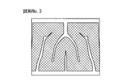
- Sample No. used in Test Example 1 It is a top view which shows 1 bipolar plate. Sample No. used in Test Example 1 It is a top view which shows 2 bipolar plates. Sample No. used in Test Example 1 3 is a plan view showing a bipolar plate 3.
- the electrode of the redox flow battery functions as a reaction field that promotes the battery reaction of the active material (metal ions) contained in the supplied electrolyte.
- a porous material such as carbon felt made of carbon fiber is usually used for the electrode, and an electrolytic solution flows in the electrode.
- a flow path having a groove through which the electrolytic solution flows is provided on the electrode side surface of the bipolar plate, the flow resistance of the electrolytic solution can be reduced, and the pressure loss due to the flow resistance of the electrolytic solution can be reduced.
- a bipolar plate having a channel having a groove the flow of the electrolyte solution penetrating into the electrode can be controlled, and the distribution of the electrolyte solution in the electrode can be suppressed from becoming non-uniform. By suppressing variations in the distribution of the electrolyte solution penetrating into the electrode, the reactivity between the electrode and the electrolyte solution can be improved, and the reaction resistance at the electrode can be reduced.
- the bipolar plate according to the embodiment is An electrode of a redox flow battery is disposed, and is a bipolar plate provided with a facing surface facing the electrode, and at least one groove constituting a flow path through which an electrolyte flows in the facing surface, When the bipolar plate is viewed in plan, at least one of the grooves has a curved portion.
- the flow path of the electrolytic solution is formed on the facing surface facing the electrode, so that the flow resistance of the electrolytic solution can be reduced and the distribution of the electrolytic solution penetrating into the electrode can be controlled. Since at least one groove constituting the flow path has a curved portion, the degree of freedom in layout is increased compared to a straight groove, so that the groove can be efficiently formed so that the distribution of the electrolyte in the electrode is uniform. It is possible to arrange. Thereby, the uniformity of the distribution of the electrolytic solution in the electrode can be sufficiently increased, and the reactivity between the electrode and the electrolytic solution can be improved. Therefore, the bipolar plate can improve the reactivity between the electrode and the electrolytic solution while reducing the flow resistance of the electrolytic solution. Therefore, when the bipolar plate is used in a redox flow battery, the reaction resistance at the electrode can be reduced while the pressure loss due to the flow resistance of the electrolyte can be reduced, so the internal resistance of the battery (cell resistance) Can be reduced.
- the “curved part” of the groove refers to a curved part in the longitudinal direction of the groove.
- the curved portion is typically a non-periodic curved shape.
- the curvature radius of the curved portion is 0.1 mm or more.
- the groove having the curved portion can be easily formed.
- the upper limit of the curvature radius of the curved portion is not particularly limited, but is, for example, 100 mm or less.
- the pressure of the electrolyte increases as it approaches the tip, and the electrolyte can easily penetrate from the groove into the electrode.
- a / (A + B) is more than 0.5 and less than 0.95, where A is the contact area in contact with the electrode and B is the planar opening area of the groove. Can be mentioned.
- the ratio [A / (A + B)] of the contact area (A) of the electrode to the area (A + B) of the opposite surface of the bipolar plate is more than 0.5, the contact area between the electrode and the bipolar plate is secured.
- the contact resistance between the electrode and the bipolar plate can be reduced.
- the internal resistance (cell resistance) of the battery can be reduced.
- the ratio [A / (A + B)] of the electrode contact area is preferably less than 0.95. Thereby, the distribution
- the “planar opening area” of the groove means the opening area of the groove on the opposite surface when the bipolar plate is viewed in plan.
- the width on the opening side of the groove is equal to or larger than the width on the bottom side.
- the cross-sectional shape of the groove is formed in a tapered shape from the opening side toward the bottom side.
- the cross section of the groove is formed in a tapered shape from the opening side to the bottom side, the electrolyte can easily penetrate from the groove into the electrode.
- the groove is formed in a dendritic shape, and includes a trunk groove part and at least one branch groove part branched from the trunk groove part, It is mentioned that at least one of the branch groove portions intersects the trunk groove portion non-orthogonally.
- the groove is formed in a dendritic shape, it is easy to permeate and diffuse the electrolytic solution from the groove over a wide range in the electrode, and the distribution of the electrolytic solution in the electrode can be made more uniform. Therefore, the reactivity between the electrode and the electrolytic solution can be further improved. Further, the branch groove portion branched from the trunk groove portion intersects the trunk groove portion in a non-orthogonal direction, so that the flow resistance of the electrolytic solution can be reduced as compared with the case where the branch groove portion is orthogonal to the trunk groove portion.
- branch groove portions has a branch groove portion that further branches from the branch groove portion.
- N natural number
- the groove width (opening width) of the branched branch groove part is reduced and narrowed.
- N the number of branches of the branch groove portion
- the number of branching means the number of times the branching part branches from the trunk part. When there is a branch groove part (primary branch groove) branched from the trunk groove part, the branching number is set to 1. When there is a branch groove part (secondary branch groove) further branched from the branch groove part, the branching number is set to 2. And count. When there is a branch groove portion (third branch groove) that further branches from the secondary branch groove, the number of branches is counted as three.
- the “N” is a natural number (1, 2, 3,).
- the contact width between the electrode and the bipolar plate can be increased and the contact resistance between the electrode and the bipolar plate can be reduced by decreasing the opening width of the branched branch groove portion step by step each time it branches.
- the flow path is An inlet and an outlet for the electrolyte;
- the introduction path and the discharge path each include at least one groove; It is mentioned that at least one of the introduction path and the discharge path includes a rectification unit that is connected to the introduction port or the discharge port and is formed along an edge of the bipolar plate.
- the electrolyte flows so as to cross between the introduction path and the discharge path. At that time, the electrolyte penetrates and diffuses into the electrode, and the electrolyte The entire electrode can be evenly distributed. As a result, the distribution of the electrolytic solution in the electrode can be made more effective and uniform, and the reactivity between the electrode and the electrolytic solution can be further improved. Further, by providing the rectifying unit, it is possible to efficiently introduce or discharge the electrolytic solution from the introduction port or the discharge port with respect to at least one of the introduction path and the discharge path.
- the effective electrode region where the bipolar plate and the electrode face each other is rectangular, and the introduction port and the discharge port are provided at diagonal positions of the effective electrode region, An angle formed by the rectifying unit and a diagonal line of the effective electrode region is 40 ° or more and 50 ° or less.
- the pressure loss in the rectification unit can be reduced by the angle between the rectification unit and the diagonal of the effective electrode region being 40 ° or more and 50 ° or less.
- the bipolar plate As one form of the bipolar plate, it can be mentioned that at least a part of the groove has a wide part having an opening width of 2 mm or more, and a convex part protruding from the bottom part is formed in the wide part.
- the cell frame according to the embodiment is The bipolar plate according to any one of (1) to (16) above and a frame body provided on the outer periphery of the bipolar plate.
- the cell frame includes the bipolar plate according to the above-described embodiment, the reactivity between the electrode and the electrolytic solution can be improved while reducing the flow resistance of the electrolytic solution. While being able to reduce, it is possible to reduce the reaction resistance at the electrode. Therefore, when the cell frame is used for a redox flow battery, the internal resistance (cell resistance) of the battery can be reduced, and the battery performance can be improved.
- the cell stack according to the embodiment is The cell frame according to (17) is provided.
- the cell stack includes the cell frame according to the above-described embodiment, so that the reaction resistance at the electrode can be reduced while the pressure loss due to the flow resistance of the electrolytic solution can be reduced. Therefore, when the cell stack is used for a redox flow battery, the internal resistance (cell resistance) of the battery can be reduced, and the battery performance can be improved.
- the redox flow battery according to the embodiment is The cell stack according to (18) is provided.
- the redox flow battery includes the cell stack according to the above-described embodiment, it is possible to reduce the reaction loss at the electrode while reducing the pressure loss due to the flow resistance of the electrolytic solution. Resistance (cell resistance) can be reduced. Therefore, the redox flow battery is excellent in battery performance.
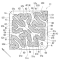
- FIG. 4 is a schematic plan view of the cell frame 3 including the bipolar plate 31 according to the embodiment when viewed from the one surface side of the bipolar plate 31.
- One of the features of the bipolar plate 31 of the embodiment is, as shown in FIG. 4, provided with at least one groove 5 constituting the flow path 4 through which the electrolytic solution flows on the facing surface facing the electrode 14, and the bipolar plate 31.
- at least one of the grooves 5 is at a point having a curved portion.
- the RF battery 1 shown in FIG. 1 and FIG. 2 uses an electrolytic solution containing, as an active material, a metal ion whose valence changes as a result of oxidation and reduction in the positive electrode electrolyte and the negative electrode electrolyte.
- the battery performs charging / discharging by utilizing the difference between the redox potential and the redox potential of ions contained in the negative electrode electrolyte.
- a vanadium-based RF battery using a vanadium electrolyte solution containing V ions in the positive electrode electrolyte and the negative electrode electrolyte is shown.
- a solid line arrow in the cell 10 in FIG. 1 indicates a charging reaction, and a broken line arrow indicates a discharging reaction.
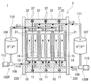
- the RF battery 1 is connected to the electric power system P via an AC / DC converter C, for example, for load leveling applications, applications such as sag compensation and emergency power supplies, natural energy power generation such as solar power generation and wind power generation. Used for output smoothing.
- the RF battery 1 includes a cell 10 for charging / discharging, tanks 106 and 107 for storing an electrolyte, and circulation channels 100P and 100N for circulating the electrolyte between the tanks 106 and 107 and the cell 10. .
- the cell 10 includes a positive electrode 14, a negative electrode 15, and a diaphragm 11 interposed between the electrodes 14 and 15.
- the structure of the cell 10 is separated into a positive electrode cell 12 and a negative electrode cell 13 with a diaphragm 11 interposed therebetween, and a positive electrode 14 is incorporated in the positive electrode cell 12 and a negative electrode 15 is incorporated in the negative electrode cell 13.
- Each electrode of the positive electrode 14 and the negative electrode 15 is formed of a carbon fiber aggregate including carbon fibers. Since the electrode of the carbon fiber aggregate is porous and has voids in the electrode, the electrolytic solution flows through the electrode, and the electrolytic solution can permeate and diffuse.
- Examples of the carbon fiber aggregate include carbon felt, carbon cloth, and carbon paper.
- Examples of the carbon fiber include PAN-based carbon fiber using polyacrylonitrile (PAN) fiber as a raw material, pitch-based carbon fiber using pitch fiber as a raw material, and rayon-based carbon fiber using rayon fiber as a raw material.
- the diaphragm 11 is formed of, for example, an ion exchange membrane that transmits hydrogen ions.
- an electrolytic solution (a positive electrode electrolytic solution and a negative electrode electrolytic solution) circulates through the circulation channels 100P and 100N.
- a positive electrode electrolyte tank 106 that stores a positive electrode electrolyte is connected to the positive electrode cell 12 via a positive electrode circulation channel 100P.
- a negative electrode electrolyte tank 107 that stores a negative electrode electrolyte is connected to the negative electrode cell 13 via a negative electrode circulation channel 100N.
- Each circulation flow path 100P, 100N has forward piping 108, 109 for sending the electrolytic solution from each tank 106, 107 to the cell 10 and return piping 110, 111 for returning the electrolytic solution from the cell 10 to each tank 106, 107.
- Pumps 112 and 113 for pumping the electrolytic solution stored in the tanks 106 and 107 are provided in the outgoing pipes 108 and 109, and the electrolytic solution is circulated to the cell 10 by the pumps 112 and 113.
- the cell 10 may be configured as a single cell including a single cell 10 or may be configured as a multi-cell including a plurality of cells 10.
- the cell 10 is normally used in a form called a cell stack 2 including a plurality of stacked cells 10 as shown in FIG.
- the cell stack 2 is configured by sandwiching the sub stack 200 from two end plates 220 from both sides and fastening the end plates 220 on both sides by a fastening mechanism 230.
- FIG. 3 illustrates a cell stack 2 including a plurality of substacks 200.
- a plurality of sub-stacks 200 are stacked in the order of the cell frame 3, the positive electrode 14, the diaphragm 11, and the negative electrode 15 (see the upper diagram of FIG.
- the cell frame 3 includes a bipolar plate 31 disposed between the positive electrode 14 and the negative electrode 15 and a frame body 32 provided around the bipolar plate 31 (see FIG. 3). (See also 4).
- the positive electrode 14 is disposed so as to face the other surface, and on the other surface side of the bipolar plate 31, the negative electrode 15 is disposed so as to face it.
- a bipolar plate 31 is provided inside the frame body 32, and a recess 32 o is formed by the bipolar plate 31 and the frame body 32.
- the recesses 32o are respectively formed on both sides of the bipolar plate 31, and the positive electrode 14 and the negative electrode 15 are accommodated in each recess 32o with the bipolar plate 31 interposed therebetween.
- Each recessed part 32o forms each cell space of the positive electrode cell 12 and the negative electrode cell 13 (refer FIG. 1).
- the planar shape of each of the positive electrode 14 and the negative electrode 15 is not particularly limited, but is rectangular in this embodiment.
- the planar opening shape of the recessed part 32o is the same rectangular shape as an electrode, and the size of the recessed part 32o and an electrode is substantially the same.
- region Effective electrode area
- the bipolar plate 31 is made of, for example, plastic carbon
- the frame body 32 is made of, for example, plastic such as vinyl chloride resin (PVC), polypropylene, polyethylene, fluorine resin, or epoxy resin.
- PVC vinyl chloride resin
- polypropylene polypropylene
- polyethylene polyethylene
- fluorine resin or epoxy resin.
- a frame 32 is integrated around the bipolar plate 31 by injection molding or the like.
- the one surface side and the other surface side of the frame 32 of each adjacent cell frame 3 face each other and face each other, and between the bipolar plates 31 of each adjacent cell frame 3 respectively.
- One cell 10 is formed.
- the electrodes 14 and 15 are accommodated in the recessed portions 32o of the frame body 32 in a compressed state in the thickness direction.
- An annular seal member 37 such as an O-ring or a flat packing is disposed between the frame bodies 32 of each cell frame 3 in order to suppress leakage of the electrolytic solution.
- a seal groove 38 (see FIG. 4) for arranging the seal member 37 is formed in the frame body 32.
- the electrolyte solution in the cell 10 flows through the supply manifolds 33 and 34 and the drainage manifolds 35 and 36 formed through the frame 32 of the cell frame 3 and the supply slits 33 s formed in the frame 32. , 34s and drainage slits 35s, 36s.
- the positive electrode electrolyte is supplied from a liquid supply manifold 33 formed in the lower part of the frame body 32 through a liquid supply slit 33s formed on one surface side of the frame body 32. Are supplied to the positive electrode 14 and discharged to the drainage manifold 35 through the drainage slit 35 s formed in the upper part of the frame 32.
- the negative electrode electrolyte is supplied from the liquid supply manifold 34 formed in the lower part of the frame 32 to the negative electrode 15 through the liquid supply slit 34 s formed on the other surface side of the frame 32, and the frame 32.
- the liquid is discharged to the drainage manifold 36 through the drainage slit 36s formed in the upper part.
- the liquid supply manifolds 33 and 34 and the drainage manifolds 35 and 36 constitute a flow path for the electrolytic solution by stacking the cell frames 3.
- These flow paths communicate with the forward pipes 108 and 109 and the return pipes 110 and 111 of the circulation flow paths 100P and 100N (see FIGS. 1 and 2) via the supply / discharge plate 210 (see the lower figure of FIG. 3), respectively. It is possible to distribute the electrolyte in the cell 10.
- the electrolytic solution is introduced from the lower side of the positive electrode 14 and the negative electrode 15, and the electrolytic solution is discharged from the upper side of the electrodes 14, 15.
- the electrolyte flows from the lower edge of 15 toward the upper edge. 2 and 3, the arrows in the electrodes 14 and 15 indicate the overall flow direction of the electrolytic solution.
- a flow path 4 through which an electrolytic solution flows is formed on the opposing surface of the bipolar plate 31 that faces the electrodes 14 and 15.
- the flow path 4 is constituted by a plurality of grooves 5 (introducing grooves 51a to 51c and discharging grooves 52a to 52c).
- the thick line arrow on the left side of the drawing indicates the overall flow direction of the electrolytic solution.
- FIG. 4 only one surface side of the bipolar plate 31 facing the positive electrode 14 is shown, but the flow path of the electrolytic solution is also provided on the other surface side of the bipolar plate 31 facing the negative electrode 15, similarly to the one surface side. Is formed. Since the structure of the negative electrode electrolyte channel formed on the other surface side of the bipolar plate 31 is the same as that of the positive electrode electrolyte channel 4 shown in FIG.
- the flow path 4 is designed so as to control the distribution of the electrolytic solution penetrating into the electrode 14 and make the distribution of the electrolytic solution in the electrode 14 uniform.
- the flow path 4 includes an inlet 4i and an outlet 4o for electrolyte.
- the introduction port 4i and the discharge port 4o are portions to which the liquid supply slit 33s and the drainage slit 35s are connected, respectively, and the electrolytic solution is introduced from the introduction port 4i through the liquid supply slit 33s, and the liquid discharge slit 35s from the discharge port 4o.
- the electrolyte is discharged.
- the introduction port 4i is positioned at the center of the lower side of the effective electrode region
- the discharge port 4o is positioned at the center of the upper side of the effective electrode region.
- the flow path 4 includes an introduction path 41 for introducing the electrolyte solution from the introduction port 4i and a discharge path 42 for discharging the electrolyte solution to the discharge port 4o.
- the introduction path 41 and the discharge path 42 are independent without communicating with each other.
- the introduction path 41 includes introduction grooves 51a to 51c
- the discharge path 42 includes discharge grooves 52a to 52c.
- the introduction path 41 and the discharge path 42 include rectifying units 510 and 520 connected to the introduction port 4i and the discharge port 4o, respectively.
- the introduction-side rectifier 510 is formed along the lower edge of the bipolar plate 31, and the discharge-side rectifier 520 is formed along the upper edge of the bipolar plate 31.
- the introduction path 41 is connected to the rectification unit 510, and the introduction grooves 51a to 51c communicate with the introduction port 4i via the rectification unit 510.
- the discharge path 42 is connected to the rectification unit 520, and the discharge grooves 52a to 52c communicate with the discharge port 4o via the rectification unit 520.
- the rectifying unit 510 diffuses the electrolyte introduced from the introduction port 4i along the lower edge of the bipolar plate 31, and introduces the electrolyte evenly into the introduction path 41 (introduction grooves 51a to 51c).
- the rectifying unit 520 collects the electrolyte discharged from the discharge path 42 (discharge grooves 52a to 52c) along the upper edge of the bipolar plate 31 to the discharge port 4o.
- the rectifiers 510 and 520 can efficiently introduce and discharge the electrolytic solution from the introduction port 4i and the discharge port 4o to the introduction path 41 and the discharge path 42, respectively.
- the flow path 4 shown in FIG. 4 has a line symmetry (left-right symmetry) with a center line (indicated by a one-dot chain line in the figure) connecting the inlet 4i and the outlet 4o as the axis of symmetry.
- the 4i side (lower side) and the outlet 4o side (upper side) are asymmetric in the vertical direction. Since the flow path 4 is formed asymmetrically between the introduction side and the discharge side, it is possible to improve the flow of the electrolyte solution on the discharge side where the pressure of the electrolyte solution decreases.
- the introduction grooves 51a to 51c constituting the introduction path 41 are connected to the rectification unit 510 on the introduction side, extend from the introduction side (lower side) to the discharge side (upper side), and the distal end side on the discharge side becomes a closed end. Yes.
- the discharge grooves 52a to 52c constituting the discharge path 42 are connected to the discharge-side rectifying unit 520 and extend from the discharge side (upper side) toward the introduction side (lower side), and the leading end side of the introduction side becomes a closed end. Yes.
- Each groove 5 (introduction grooves 51a to 51c and discharge grooves 52a to 52c) is open on the surface of the bipolar plate 31 facing the electrode 14, and as shown in FIG. It is formed so as to become smaller toward.
- the opening width decreases toward the tip side, so that the pressure of the electrolyte increases as it approaches the tip side, and the electrolyte solution easily penetrates into the electrode 14 from the introduction grooves 51a to 51c.
- the “opening width” of the groove 5 refers to a groove width orthogonal to the longitudinal direction of the groove 5.
- the opening width (groove width) and depth (groove depth) of the groove 5 can be appropriately selected according to the size and thickness of the bipolar plate 31 and are not particularly limited.
- the groove width is, for example, from 0.2 mm to 10 mm, further from 0.5 mm to 5 mm, and the groove depth is, for example, from 0.5 mm to 5 mm, further from 1 mm to 3 mm.
- the surface of the bipolar plate 31 is cut with a cutting tool such as an end mill.
- a cutting tool such as an end mill.
- a / (A + B) is preferably more than 0.5 and less than 0.95.
- the ratio [A / (A + B)] of the contact area (A) of the electrode 14 to the area (A + B) of the opposite surface of the bipolar plate 31 is more than 0.5, the contact area between the electrode 14 and the bipolar plate 31 And the contact resistance between the electrode 14 and the bipolar plate 31 can be reduced. Thereby, the internal resistance (cell resistance) of the battery can be reduced. Further, from the viewpoint of securing the formation area of the groove 5 (the flow path area of the electrolytic solution) on the facing surface of the bipolar plate 31, the ratio [A / (A + B)] of the contact area of the electrode 14 is less than 0.95. Is preferable, and the flow resistance of the electrolytic solution can be effectively reduced.
- the ratio [A / (A + B)] of the contact area of the electrode 14 is, for example, 0.6 or more and 0.9 or less, and more preferably 0.7 or more and 0.8 or less.
- the “planar opening area” of the groove 5 refers to the opening area of the groove 5 on the facing surface when the bipolar plate 31 is viewed in plan.
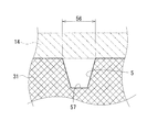
- FIG. 6 shows a cross-sectional shape of the groove 5 in the present embodiment.
- the width of the groove 5 on the opening 56 side is equal to or larger than the width on the bottom 57 side in the cross section orthogonal to the flow direction of the electrolyte in the groove 5.
- the cross-sectional shape is tapered from the opening 56 side toward the bottom 57 side. Therefore, when the width of the groove 56 on the opening 56 side is equal to or larger than the width of the bottom 57 side, the groove 5 is formed compared to the case where the width on the bottom 57 side is wider than the width on the opening 56 side. easy.
- the cross-sectional shape of the groove 5 (particularly, the introduction grooves 51a to 51c) is tapered from the opening 56 side toward the bottom 57 side, the electrolytic solution can easily penetrate from the groove 5 into the electrode.
- the cross-sectional shape of the groove 5 include a rectangular shape, a triangular shape (V shape), a trapezoidal shape, a semicircular shape, and a semielliptical shape.
- the introduction grooves 51 a and 51 c and the discharge grooves 52 a and 52 c are dendritic grooves formed in a dendritic shape. 61. Since at least one of the grooves 5 is formed in a dendritic shape, it is easy to permeate and diffuse the electrolytic solution over a wide range in the electrode 14, and the distribution of the electrolytic solution in the electrode 14 can be made more uniform. . Therefore, the reactivity between the electrode 14 and the electrolytic solution can be further improved.
- the “trunk groove portion” refers to a groove portion that is directly connected to the introduction port 4 i or the discharge port 4 o or indirectly through the rectifying units 510 and 520.
- the “branch groove portion” refers to a groove portion branched from the trunk groove portion 60 and having a smaller opening width than the trunk groove portion 60.
- the branch groove part 61 may have a branch groove part 62 that further branches from the branch groove part 61.
- the branch groove portion 61 is called a primary branch groove
- the branch groove portion 62 is called a secondary branch groove.
- the opening width of the branch groove portion 62 (secondary branch groove) after branching is smaller than the opening width of the branch groove portion 61 (primary branch groove) before branching.
- FIG. 5 shows a drawing of the introduction groove 51c, and the relationship between the trunk groove part 60 and the branch groove part 61, and the branch groove part 61 and the branch groove part 62 will be described by taking the introduction groove 51c as an example.
- the opening width (W a1 ) of the branch groove portion 61 is smaller than the opening width (W a0 ) of the trunk groove portion 60 at a location where the branch groove portion 61 branches from the trunk groove portion 60.
- the opening width (W a2 ) of the branch groove portion 62 is smaller than the opening width (W b1 ) of the branch groove portion 61.
- N is preferably 3 or less, where N (N: natural number) is the number of branches in the branch groove portion.
- the “branching frequency” here means the number of times the branch groove part branches from the trunk groove part. For example, in the introduction groove 51c and the discharge groove 52a, the branching frequency N of the branching groove 61 that branches from the trunk groove 60 is 1, and the branching frequency N of the branching groove 62 that further branches from the branching groove 61 is 2. If there is another branch groove part that further branches from the branch groove part 62, the branching frequency N is three.
- the groove widths (opening widths) of the branched groove portions 61 and 62 are reduced and narrowed.
- the branching frequency N By restricting the branching frequency N to 3 or less as in the present embodiment, excessive narrowing of the groove widths of the branch groove portions 61 and 62 due to branching can be avoided.
- the branch groove part 61 intersects the trunk groove part 60 non-orthogonally.
- the flow resistance of the electrolytic solution can be reduced as compared with the case where the branch groove portion 61 is orthogonal to the trunk groove portion 60.
- “Intersecting non-orthogonally” typically refers to a case where the inclination angle ⁇ (see FIG. 5) in the extending direction of the branch groove portion 61 with respect to the extending direction of the trunk groove portion 60 is an acute angle.
- the inclination angle ⁇ is, for example, not less than 10 ° and not more than 80 °.
- the introduction grooves 51a to 51c of the introduction path 41 and the discharge grooves 52a to 52c of the discharge path 42 have opposing comb tooth regions that are alternately arranged facing each other.
- the branch groove portions 61 of the introduction groove 51a and the branch groove portions 62 of the discharge groove 52a are alternately arranged facing each other, and these also form an opposing comb tooth region.
- the flow path 4 has the opposing comb tooth region, the amount of the electrolyte flowing so as to cross between the introduction path 41 (introduction grooves 51a to 51c) and the discharge path 42 (discharge grooves 52a to 52c) increases.
- the electrolyte solution that permeates and diffuses into the electrode 14 increases. Thereby, the reaction efficiency of the electrode 14 and electrolyte solution can be improved.
- a convex portion 59 protruding from the bottom portion may be formed in the wide portion. Since the convex portion 59 is provided in the wide portion of the groove 5, it is possible to suppress the electrode 14 from being buried in the groove 5.
- the base end sides (sides connected to the rectifying units 510 and 520) of the introduction groove 51a and the discharge groove 52a are partially widened, and the portion Convex part 59 is provided in this.
- the shape of the convex portion 59 when viewed in plan is not particularly limited, and various shapes such as a polygonal shape such as a triangle and a quadrangle, a circular shape, and an elliptical shape can be employed. Further, the number of the convex portions 59 arranged in the wide portion may be one or plural.
- the grooves 5 has a curved portion.
- the “curved portion” refers to a portion that is curved in the longitudinal direction of the groove 5, and is typically a non-periodic curved shape.
- the branch groove portions 61 and 62 of the introduction groove 51c and the branch groove portions 61 and 62 of the discharge groove 52a are formed in a curved shape, and each is constituted by a curved portion.
- the curvature radius of the curved portion is, for example, 0.1 mm or more, further 1 mm or more, and further 3 mm or more.
- the flow path 4 of the electrolytic solution is formed on the opposing surface facing the electrode 14, so that the flow resistance of the electrolytic solution can be reduced and the electrolysis that penetrates into the electrode 14.
- the liquid distribution can be controlled. Since at least one groove 5 constituting the flow path 4 has a curved portion, the degree of freedom in layout is increased as compared with a linear groove, so that the distribution of the electrolyte in the electrode 14 is uniform. It is possible to arrange the grooves 5 efficiently. Thereby, the uniformity of the distribution of the electrolytic solution in the electrode 14 can be sufficiently increased, and the reactivity between the electrode 14 and the electrolytic solution can be improved.
- the bipolar plate 31 can improve the reactivity between the electrode 14 and the electrolytic solution while reducing the flow resistance of the electrolytic solution. Therefore, when the bipolar plate 31 of the embodiment is used for the RF battery 1, it is possible to reduce the reaction resistance at the electrode 14 while reducing the pressure loss due to the flow resistance of the electrolytic solution. (Cell resistance) can be reduced.
- the groove 5 has a curved portion, the direction of the electrolytic solution flowing in the groove 5 can be changed smoothly, and the flow resistance can be easily reduced even when the electrolytic solution flows smoothly compared to the case where the groove 5 is bent at a right angle or an acute angle.
- the cell frame 3 includes the bipolar plate 31, the reactivity between the electrode 14 and the electrolytic solution can be improved while reducing the flow resistance of the electrolytic solution.
- the reaction resistance at the electrode 14 can be reduced.
- the cell stack 2 includes the cell frame 3, it is possible to reduce the reaction resistance at the electrode 14 while reducing the pressure loss due to the flow resistance of the electrolytic solution.
- the reaction resistance at the electrode 14 can be reduced while the pressure loss due to the flow resistance of the electrolytic solution can be reduced. Resistance (cell resistance) can be reduced.
- the effective electrode area of the bipolar plate 31 shown in FIG. 7 is rectangular.
- the inlet 4i is located at the lower right corner of the effective electrode region
- the outlet 4o is located at the upper left corner of the effective electrode region
- the inlet 4i and the outlet 4o Are provided at diagonal positions of the effective electrode region.
- the rectification unit 510 formed along the lower edge of the bipolar plate 31 and the right edge of the bipolar plate 31 are formed as the rectification unit on the introduction side connected to the introduction port 4i.
- a rectifying unit 511 is included.
- a discharge side rectification unit connected to the discharge port 4o a rectification unit 520 formed along the upper edge of the bipolar plate 31 and a rectification unit 521 formed along the left edge of the bipolar plate 31 are provided.
- the rectification units 510 and 511 on the introduction side and the rectification units 520 and 521 on the discharge side are formed so as not to communicate with each other.
- the introduction path 41 includes introduction grooves 51a to 51d connected to the introduction-side rectifying sections 510 and 511
- the discharge path 42 includes discharge grooves 52a to 52d connected to the discharge-side rectification sections 520 and 521.
- the introduction grooves 51 c and 51 d and the discharge groove 52 c are dendritic grooves formed in a dendritic shape, and include a trunk groove part 60 and a branch groove part 61 branched from the trunk groove part 60.
- the branch groove part 61 intersects the trunk groove part 60 non-orthogonally.
- the branch groove portions 61 of the introduction grooves 51c and 51d and the branch groove portion 61 of the discharge groove 52c have curved portions.
- the flow path 4 is line-symmetric with respect to a diagonal line (indicated by a one-dot chain line in the figure) connecting the inlet 4i and the outlet 4o.
- the angle formed by the rectifying units 510 and 520 and the diagonal line of the effective electrode region (the diagonal line connecting the inlet 4i and the outlet 4o) is 40 ° or more and 50 ° or less.
- the pressure loss in the rectifying units 510 and 520 can be reduced by setting the angle formed by each of the rectifying units 510 and 520 and the diagonal line of the effective electrode region within the above range.
- the intermediate groove 54 is an independent closed groove that does not communicate with the introduction-side rectifying portions 510 and 511, the discharge-side rectifying portions 520 and 521, and the introduction grooves 51a to 51d and the discharge grooves 52a to 52d.
- the intermediate groove 54 is a dendritic groove extending along the diagonal line and formed in a dendritic shape from the intermediate portion in the longitudinal direction toward both ends.
- the trunk groove part 60 located in the intermediate part of the longitudinal direction of the intermediate groove 54, and the branch groove part 61 branched from each edge part of the introduction side (lower right side) and discharge
- the branch groove portions 62 further branch from the respective branch groove portions 61.
- the branch groove portion 61 intersects the trunk groove portion 60 non-orthogonally, and the branch groove portions 61 and 62 have curved portions.
- the opposed comb tooth region formed by the introduction grooves 51a to 51c or the discharge grooves 52a to 52c and the intermediate groove 54 in addition to the opposing comb tooth region formed by the introduction grooves 51c and 51d and the discharge grooves 52c and 52d, the opposed comb tooth region formed by the introduction grooves 51a to 51c or the discharge grooves 52a to 52c and the intermediate groove 54.
- the electrolyte solution can be easily diffused over a wide range and the electrolysis in the electrode can be performed. It is easy to make the liquid distribution more uniform.
- the introduction groove 51a and the trunk groove part 60 of the intermediate groove 54 each have a wide part, and the convex part 59 is arranged in each wide part.
- Test Example 1 A bipolar plate having an electrolyte flow path corresponding to the embodiment was fabricated, and an RF battery was assembled using the bipolar plate, and the cell resistivity was examined.
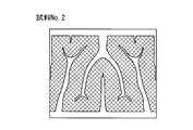
- test Example 1 sample No. 1 in which the flow path shown in FIGS. 1-No. Three grooved bipolar plates were prepared.
- the material of the bipolar plate is plastic carbon.
- the bipolar plate No. 3 has the same shape and size, and only the flow path is different, and the electrode contact area A on the surface facing the electrode and the planar opening area B of the grooves constituting the flow path are different.
- the area (A + B) of the opposing surface of each bipolar plate is the same at 891 mm 2 (27 mm ⁇ 33 mm).
- Table 1 shows the electrode contact area A of the bipolar plate in each sample and the ratio [A / (A + B)] of the electrode contact area (A) to the area (A + B) of the facing surface.
- the numerical value of the electrode contact area ratio [A / (A + B)] shown in Table 1 is a value obtained by rounding down the third decimal place.
- Sample No. 1-No. A single cell RF battery was assembled using 3 bipolar plates.
- the single cell was prepared by placing positive and negative electrodes on both sides of the diaphragm and sandwiching the cell frame with bipolar plates from both sides. Carbon felt was used for each positive and negative electrode.
Landscapes
- Life Sciences & Earth Sciences (AREA)
- Engineering & Computer Science (AREA)
- Manufacturing & Machinery (AREA)
- Sustainable Development (AREA)
- Sustainable Energy (AREA)
- Chemical & Material Sciences (AREA)
- Chemical Kinetics & Catalysis (AREA)
- Electrochemistry (AREA)
- General Chemical & Material Sciences (AREA)
- Fuel Cell (AREA)
Abstract
A bipolar plate having an electrode of a redox flow battery positioned thereon and comprising: a facing surface that faces said electrode; and at least one groove that forms, in the facing surface, a flow path through which an electrolytic solution flows, wherein when the bipolar plate is in planar view, at least one of the grooves has a curved section.
Description
本発明は、双極板、セルフレーム、セルスタック、及びレドックスフロー電池に関する。
The present invention relates to a bipolar plate, a cell frame, a cell stack, and a redox flow battery.
大容量の蓄電池の一つとして、レドックスフロー電池(以下、「RF電池」と呼ぶ場合がある)が知られている(例えば、特許文献1、2を参照)。一般的に、RF電池では、セルフレーム、正極電極、隔膜、負極電極をそれぞれ複数積層してなるセルスタックが使用されている。セルフレームは、正極電極と負極電極との間に配置される双極板と、双極板の外周に設けられる枠体とを備えている。セルスタックは、隣接するセルフレームの双極板の間に、隔膜を挟んで正負の電極が配置され、1つのセルが形成される。RF電池は、電極が内蔵されたセルに電解液をポンプで循環させて充放電を行う。
As one of large-capacity storage batteries, a redox flow battery (hereinafter sometimes referred to as “RF battery”) is known (see, for example, Patent Documents 1 and 2). In general, an RF battery uses a cell stack in which a plurality of cell frames, positive electrodes, diaphragms, and negative electrodes are stacked. The cell frame includes a bipolar plate disposed between the positive electrode and the negative electrode, and a frame provided on the outer periphery of the bipolar plate. In the cell stack, positive and negative electrodes are arranged between bipolar plates of adjacent cell frames with a diaphragm interposed therebetween to form one cell. The RF battery performs charging / discharging by circulating an electrolyte solution in a cell containing an electrode by a pump.
特許文献1、2には、双極板の電極側の面に電解液が流通する複数の溝を形成して流路を構成することが記載されている。
Patent Documents 1 and 2 describe that a channel is formed by forming a plurality of grooves through which an electrolytic solution flows on the electrode side surface of a bipolar plate.
本開示の双極板は、
レドックスフロー電池の電極が配置され、前記電極に対向する対向面と、前記対向面に電解液が流通する流路を構成する少なくとも1つの溝とを備える双極板であって、
前記双極板を平面視したとき、前記溝の少なくとも1つは曲線部を有する。 The bipolar plate of the present disclosure is
An electrode of a redox flow battery is disposed, and is a bipolar plate provided with a facing surface facing the electrode, and at least one groove constituting a flow path through which an electrolyte flows in the facing surface,
When the bipolar plate is viewed in plan, at least one of the grooves has a curved portion.
本開示のセルフレームは、
上記本開示の双極板と、前記双極板の外周に設けられる枠体とを備える。 The cell frame of the present disclosure is
The bipolar plate of the present disclosure and a frame body provided on the outer periphery of the bipolar plate.
上記本開示の双極板と、前記双極板の外周に設けられる枠体とを備える。 The cell frame of the present disclosure is
The bipolar plate of the present disclosure and a frame body provided on the outer periphery of the bipolar plate.
本開示のセルスタックは、
上記本開示のセルフレームを備える。 The cell stack of the present disclosure is
The cell frame of the present disclosure is provided.
上記本開示のセルフレームを備える。 The cell stack of the present disclosure is
The cell frame of the present disclosure is provided.
本開示のレドックスフロー電池は、
上記本開示のセルスタックを備える。 The redox flow battery of the present disclosure is
The cell stack of the present disclosure is provided.
上記本開示のセルスタックを備える。 The redox flow battery of the present disclosure is
The cell stack of the present disclosure is provided.
[本開示が解決しようとする課題]
レドックスフロー電池の更なる電池性能の向上が望まれており、電池性能を向上する観点から、電池の内部抵抗(セル抵抗)を低減することが求められている。内部抵抗の要因としては、電解液の流通状態、例えば、電解液の流通抵抗、電極での反応抵抗などが挙げられる。 [Problems to be solved by the present disclosure]
Further improvement of the battery performance of the redox flow battery is desired. From the viewpoint of improving the battery performance, it is required to reduce the internal resistance (cell resistance) of the battery. As a factor of the internal resistance, there are a flow state of the electrolytic solution, for example, a flow resistance of the electrolytic solution, a reaction resistance at the electrode, and the like.
レドックスフロー電池の電極は、供給された電解液に含まれる活物質(金属イオン)の電池反応を促進させる反応場として機能する。電極には、通常、炭素繊維からなるカーボンフェルトなどの多孔質材料が利用されており、電極内に電解液が流通する。双極板の電極側の面に電解液が流通する溝を有する流路を備える場合、電解液の流通抵抗を低減でき、電解液の流通抵抗による圧力損失を低減できる。また、溝を有する流路を備える双極板を用いることで、電極内に浸透する電解液の流れを制御して、電極内での電解液の分布が不均一になることを抑制できる。電極内に浸透する電解液の分布のバラツキを抑制することにより、電極と電解液との反応性を向上でき、電極での反応抵抗を低減できる。
The electrode of the redox flow battery functions as a reaction field that promotes the battery reaction of the active material (metal ions) contained in the supplied electrolyte. A porous material such as carbon felt made of carbon fiber is usually used for the electrode, and an electrolytic solution flows in the electrode. When a flow path having a groove through which the electrolytic solution flows is provided on the electrode side surface of the bipolar plate, the flow resistance of the electrolytic solution can be reduced, and the pressure loss due to the flow resistance of the electrolytic solution can be reduced. Further, by using a bipolar plate having a channel having a groove, the flow of the electrolyte solution penetrating into the electrode can be controlled, and the distribution of the electrolyte solution in the electrode can be suppressed from becoming non-uniform. By suppressing variations in the distribution of the electrolyte solution penetrating into the electrode, the reactivity between the electrode and the electrolyte solution can be improved, and the reaction resistance at the electrode can be reduced.
しかしながら、従来では、電極での電解液の流通状態を十分に考慮した上で内部抵抗を低減することについて、必ずしも十分な検討がなされているとはいえなかった。従来の双極板は、流路が主として直線状の溝で構成されているため、溝のレイアウトの自由度が低く、電極内での電解液の分布の均一性を十分に高めることが難しいなど、電極と電解液との反応性を改善する余地がある。
However, in the past, it has not necessarily been fully studied to reduce the internal resistance after sufficiently considering the flow state of the electrolyte solution at the electrode. In the conventional bipolar plate, since the flow path is mainly composed of linear grooves, the degree of freedom in the layout of the grooves is low, and it is difficult to sufficiently improve the uniformity of the distribution of the electrolyte in the electrodes. There is room for improving the reactivity between the electrode and the electrolyte.
そこで、本開示は、電解液の流通抵抗を低減しつつ、電極と電解液との反応性を向上できる双極板を提供することを目的の一つとする。また、本開示は、電池性能を向上できるセルフレーム及びセルスタックを提供することを目的の一つとする。更に、本開示は、電池性能に優れるレドックスフロー電池を提供することを目的の一つとする。
Therefore, an object of the present disclosure is to provide a bipolar plate that can improve the reactivity between the electrode and the electrolyte while reducing the flow resistance of the electrolyte. Another object of the present disclosure is to provide a cell frame and a cell stack that can improve battery performance. Furthermore, an object of the present disclosure is to provide a redox flow battery having excellent battery performance.
[本開示の効果]
本開示によれば、電解液の流通抵抗を低減しつつ、電極と電解液との反応性を向上できる双極板を提供できる。また、本開示によれば、電池性能を向上できるセルフレーム及びセルスタックを提供できる。更に、本開示によれば、電池性能に優れるレドックスフロー電池を提供できる。 [Effects of the present disclosure]
According to the present disclosure, it is possible to provide a bipolar plate that can improve the reactivity between the electrode and the electrolytic solution while reducing the flow resistance of the electrolytic solution. Moreover, according to this indication, the cell frame and cell stack which can improve battery performance can be provided. Furthermore, according to the present disclosure, a redox flow battery having excellent battery performance can be provided.
[本願発明の実施形態の説明]
最初に本願発明の実施形態の内容を列記して説明する。 [Description of Embodiment of Present Invention]
First, the contents of the embodiments of the present invention will be listed and described.
最初に本願発明の実施形態の内容を列記して説明する。 [Description of Embodiment of Present Invention]
First, the contents of the embodiments of the present invention will be listed and described.
(1)実施形態に係る双極板は、
レドックスフロー電池の電極が配置され、前記電極に対向する対向面と、前記対向面に電解液が流通する流路を構成する少なくとも1つの溝とを備える双極板であって、
前記双極板を平面視したとき、前記溝の少なくとも1つは曲線部を有する。 (1) The bipolar plate according to the embodiment is
An electrode of a redox flow battery is disposed, and is a bipolar plate provided with a facing surface facing the electrode, and at least one groove constituting a flow path through which an electrolyte flows in the facing surface,
When the bipolar plate is viewed in plan, at least one of the grooves has a curved portion.
上記双極板によれば、電極に対向する対向面に電解液の流路が形成されていることで、電解液の流通抵抗を低減できると共に、電極内に浸透する電解液の分布を制御できる。流路を構成する少なくとも1つの溝が曲線部を有することで、直線状の溝に比べてレイアウトの自由度が上がるため、電極内における電解液の分布が均一になるように溝を効率的に配置することが可能である。これにより、電極内での電解液の分布の均一性を十分に高めることができ、電極と電解液との反応性を向上させることができる。したがって、上記双極板は、電解液の流通抵抗を低減しつつ、電極と電解液との反応性を向上できる。よって、上記双極板をレドックスフロー電池に用いた場合、電解液の流通抵抗による圧力損失を低減できながら、電極での反応抵抗を低減することが可能であるので、電池の内部抵抗(セル抵抗)を低減することが可能である。
According to the bipolar plate, the flow path of the electrolytic solution is formed on the facing surface facing the electrode, so that the flow resistance of the electrolytic solution can be reduced and the distribution of the electrolytic solution penetrating into the electrode can be controlled. Since at least one groove constituting the flow path has a curved portion, the degree of freedom in layout is increased compared to a straight groove, so that the groove can be efficiently formed so that the distribution of the electrolyte in the electrode is uniform. It is possible to arrange. Thereby, the uniformity of the distribution of the electrolytic solution in the electrode can be sufficiently increased, and the reactivity between the electrode and the electrolytic solution can be improved. Therefore, the bipolar plate can improve the reactivity between the electrode and the electrolytic solution while reducing the flow resistance of the electrolytic solution. Therefore, when the bipolar plate is used in a redox flow battery, the reaction resistance at the electrode can be reduced while the pressure loss due to the flow resistance of the electrolyte can be reduced, so the internal resistance of the battery (cell resistance) Can be reduced.
溝の「曲線部」とは、溝の長手方向において曲線状をなす部分をいう。曲線部は、代表的には、非周期的な曲線状である。
The “curved part” of the groove refers to a curved part in the longitudinal direction of the groove. The curved portion is typically a non-periodic curved shape.
(2)上記双極板の一形態として、
前記曲線部の曲率半径が0.1mm以上であることが挙げられる。 (2) As one form of the bipolar plate,
It is mentioned that the curvature radius of the curved portion is 0.1 mm or more.
前記曲線部の曲率半径が0.1mm以上であることが挙げられる。 (2) As one form of the bipolar plate,
It is mentioned that the curvature radius of the curved portion is 0.1 mm or more.
曲線部の曲率半径が0.1mm以上であることで、曲線部を有する溝の形成が容易である。曲線部の曲率半径の上限は、特に問わないが、例えば100mm以下である。
When the radius of curvature of the curved portion is 0.1 mm or more, the groove having the curved portion can be easily formed. The upper limit of the curvature radius of the curved portion is not particularly limited, but is, for example, 100 mm or less.
(3)上記双極板の一形態として、
前記溝の開口幅が先端側に向かって小さくなることが挙げられる。 (3) As one form of the bipolar plate,
It is mentioned that the opening width of the groove becomes smaller toward the tip side.
前記溝の開口幅が先端側に向かって小さくなることが挙げられる。 (3) As one form of the bipolar plate,
It is mentioned that the opening width of the groove becomes smaller toward the tip side.
溝の開口幅が先端側に向かって小さくなることで、先端側に近づくにつれて電解液の圧力が高くなり、溝から電極内へ電解液を浸透させ易い。
As the opening width of the groove decreases toward the tip, the pressure of the electrolyte increases as it approaches the tip, and the electrolyte can easily penetrate from the groove into the electrode.
(4)上記双極板の一形態として、
前記双極板の前記対向面のうち、前記電極と接触する接触面積をA、前記溝の平面開口面積をBとするとき、A/(A+B)が0.5超0.95未満であることが挙げられる。 (4) As one form of the bipolar plate,
Of the opposing surfaces of the bipolar plate, A / (A + B) is more than 0.5 and less than 0.95, where A is the contact area in contact with the electrode and B is the planar opening area of the groove. Can be mentioned.
双極板の対向面の面積(A+B)に占める電極の接触面積(A)の割合[A/(A+B)]が0.5超であることで、電極と双極板との接触面積を確保して、電極と双極板間の接触抵抗を低減できる。これにより、電池の内部抵抗(セル抵抗)を低減することが可能である。また、双極板の対向面における溝の形成面積(電解液の流路面積)を確保する観点から、電極の接触面積の割合[A/(A+B)]は0.95未満であることが好ましく、これにより、電解液の流通抵抗を効果的に低減できる。
Since the ratio [A / (A + B)] of the contact area (A) of the electrode to the area (A + B) of the opposite surface of the bipolar plate is more than 0.5, the contact area between the electrode and the bipolar plate is secured. The contact resistance between the electrode and the bipolar plate can be reduced. Thereby, the internal resistance (cell resistance) of the battery can be reduced. In addition, from the viewpoint of ensuring the groove formation area (electrolyte flow path area) on the opposing surface of the bipolar plate, the ratio [A / (A + B)] of the electrode contact area is preferably less than 0.95. Thereby, the distribution | circulation resistance of electrolyte solution can be reduced effectively.
溝の「平面開口面積」とは、双極板を平面視したとき、対向面における溝の開口面積をいう。
The “planar opening area” of the groove means the opening area of the groove on the opposite surface when the bipolar plate is viewed in plan.
(5)上記双極板の一形態として、
前記溝の電解液の流通方向に直交する断面において、前記溝の開口部側の幅が底部側の幅以上であることが挙げられる。 (5) As one form of the bipolar plate,
In the cross section orthogonal to the flow direction of the electrolytic solution in the groove, the width on the opening side of the groove is equal to or larger than the width on the bottom side.
前記溝の電解液の流通方向に直交する断面において、前記溝の開口部側の幅が底部側の幅以上であることが挙げられる。 (5) As one form of the bipolar plate,
In the cross section orthogonal to the flow direction of the electrolytic solution in the groove, the width on the opening side of the groove is equal to or larger than the width on the bottom side.
溝の断面において、溝の開口部側の幅が底部側の幅以上であることで、開口部側の幅よりも底部側の幅の方が広い場合に比べて、溝を形成し易い。
In the cross section of the groove, when the width on the opening side of the groove is equal to or larger than the width on the bottom side, it is easier to form the groove than when the width on the bottom side is wider than the width on the opening side.
(6)上記(5)に記載の双極板の一形態として、
前記溝の断面形状が開口部側から底部側に向けてテーパ状に形成されていることが挙げられる。 (6) As one form of the bipolar plate described in (5) above,
It is mentioned that the cross-sectional shape of the groove is formed in a tapered shape from the opening side toward the bottom side.
前記溝の断面形状が開口部側から底部側に向けてテーパ状に形成されていることが挙げられる。 (6) As one form of the bipolar plate described in (5) above,
It is mentioned that the cross-sectional shape of the groove is formed in a tapered shape from the opening side toward the bottom side.
溝の断面が開口部側から底部側に向けてテーパ状に形成されていることで、溝から電極内へ電解液を浸透させ易い。
Since the cross section of the groove is formed in a tapered shape from the opening side to the bottom side, the electrolyte can easily penetrate from the groove into the electrode.
(7)上記双極板の一形態として、
前記溝は、樹枝状に形成され、幹溝部と、前記幹溝部から分岐する少なくとも1つの枝溝部とを備え、
前記枝溝部の少なくとも1つは、前記幹溝部に対して非直交に交差することが挙げられる。 (7) As one form of the bipolar plate,
The groove is formed in a dendritic shape, and includes a trunk groove part and at least one branch groove part branched from the trunk groove part,
It is mentioned that at least one of the branch groove portions intersects the trunk groove portion non-orthogonally.
溝が樹枝状に形成されていることで、溝から電極内の広範囲にわたって電解液を浸透・拡散させ易く、電極内での電解液の分布をより均一にすることが可能である。よって、電極と電解液との反応性をより向上できる。また、幹溝部から分岐する枝溝部が幹溝部に対して非直交に交差することにより、枝溝部が幹溝部に直交する場合に比べて、電解液の流通抵抗を低減することが可能である。
Since the groove is formed in a dendritic shape, it is easy to permeate and diffuse the electrolytic solution from the groove over a wide range in the electrode, and the distribution of the electrolytic solution in the electrode can be made more uniform. Therefore, the reactivity between the electrode and the electrolytic solution can be further improved. Further, the branch groove portion branched from the trunk groove portion intersects the trunk groove portion in a non-orthogonal direction, so that the flow resistance of the electrolytic solution can be reduced as compared with the case where the branch groove portion is orthogonal to the trunk groove portion.
(8)上記(7)に記載の双極板の一形態として、
前記枝溝部の少なくとも1つに前記曲線部を有することが挙げられる。 (8) As one form of the bipolar plate described in (7) above,
It is mentioned that at least one of the branch groove portions has the curved portion.
前記枝溝部の少なくとも1つに前記曲線部を有することが挙げられる。 (8) As one form of the bipolar plate described in (7) above,
It is mentioned that at least one of the branch groove portions has the curved portion.
枝溝部に曲線部を有することで、溝を効率的に配置することが可能である。
It is possible to arrange the grooves efficiently by having the curved part in the branch groove part.
(9)上記(7)又は(8)に記載の双極板の一形態として、
前記枝溝部の少なくとも1つは、当該枝溝部から更に分岐する枝溝部を有することが挙げられる。 (9) As one form of the bipolar plate described in (7) or (8) above,
It is mentioned that at least one of the branch groove portions has a branch groove portion that further branches from the branch groove portion.
前記枝溝部の少なくとも1つは、当該枝溝部から更に分岐する枝溝部を有することが挙げられる。 (9) As one form of the bipolar plate described in (7) or (8) above,
It is mentioned that at least one of the branch groove portions has a branch groove portion that further branches from the branch groove portion.
枝溝部から更に分岐する枝溝部を有することで、電極内に電解液を効果的に浸透・拡散させ易い。
By having a branch groove part that further branches from the branch groove part, it is easy to effectively permeate and diffuse the electrolyte into the electrode.
(10)上記(9)に記載の双極板の一形態として、
前記枝溝部の枝分かれ回数をN(N:自然数)とするとき、Nが3以下であることが挙げられる。 (10) As one form of the bipolar plate described in (9) above,
When the branching frequency of the branch groove portion is N (N: natural number), N is 3 or less.
前記枝溝部の枝分かれ回数をN(N:自然数)とするとき、Nが3以下であることが挙げられる。 (10) As one form of the bipolar plate described in (9) above,
When the branching frequency of the branch groove portion is N (N: natural number), N is 3 or less.
幹溝部から枝分かれを繰り返すことによって、枝分かれした枝溝部の溝幅(開口幅)が減少し、狭小化する。枝溝部の枝分かれ回数(N)を3以下に制限することで、枝分かれによる枝溝部の溝幅の過度な狭小化を回避できる。
繰 り 返 す By repeating branching from the trunk groove part, the groove width (opening width) of the branched branch groove part is reduced and narrowed. By restricting the number of branches (N) of the branch groove portion to 3 or less, excessive narrowing of the groove width of the branch groove portion due to branching can be avoided.
「枝分かれ回数」とは、幹溝部から数えて枝溝部が分岐する回数を意味する。幹溝部から分岐する枝溝部(1次枝溝)があるときは、その枝分かれ回数を1とし、この枝溝部から更に分岐する枝溝部(2次枝溝)があるときは、その枝分かれ回数を2と数える。そして、この2次枝溝から更に分岐する枝溝部(3次枝溝)があるときは、その枝分かれ回数を3と数える。上記「N」は自然数(1,2,3,…)である。
“The number of branching” means the number of times the branching part branches from the trunk part. When there is a branch groove part (primary branch groove) branched from the trunk groove part, the branching number is set to 1. When there is a branch groove part (secondary branch groove) further branched from the branch groove part, the branching number is set to 2. And count. When there is a branch groove portion (third branch groove) that further branches from the secondary branch groove, the number of branches is counted as three. The “N” is a natural number (1, 2, 3,...).
(11)上記(9)又は(10)に記載の双極板の一形態として、
枝分かれ後の前記枝溝部の開口幅が枝分かれ前の前記枝溝部の開口幅よりも小さいことが挙げられる。 (11) As one form of the bipolar plate described in (9) or (10) above,
It is mentioned that the opening width of the branch groove part after branching is smaller than the opening width of the branch groove part before branching.
枝分かれ後の前記枝溝部の開口幅が枝分かれ前の前記枝溝部の開口幅よりも小さいことが挙げられる。 (11) As one form of the bipolar plate described in (9) or (10) above,
It is mentioned that the opening width of the branch groove part after branching is smaller than the opening width of the branch groove part before branching.
枝分かれした枝溝部の開口幅が分岐を経るごとに段階的に小さくなることで、電極と双極板との接触面積が増え、電極と双極板間の接触抵抗を低減できる。
The contact width between the electrode and the bipolar plate can be increased and the contact resistance between the electrode and the bipolar plate can be reduced by decreasing the opening width of the branched branch groove portion step by step each time it branches.
(12)上記双極板の一形態として、
前記流路は、
前記電解液の導入口及び排出口と、
前記導入口から前記電解液を導入する導入路と、前記導入路とは連通せずに独立して、前記電解液を前記排出口に排出する排出路とを備え、
前記導入路及び前記排出路がそれぞれ少なくとも1つの前記溝を備えており、
前記導入路及び前記排出路の少なくとも一方は、前記導入口又は前記排出口に接続されて前記双極板の縁部に沿って形成される整流部を備えることが挙げられる。 (12) As one form of the bipolar plate,
The flow path is
An inlet and an outlet for the electrolyte;
An introduction path for introducing the electrolyte solution from the introduction port, and a discharge path for discharging the electrolyte solution to the discharge port independently without communicating with the introduction path,
The introduction path and the discharge path each include at least one groove;
It is mentioned that at least one of the introduction path and the discharge path includes a rectification unit that is connected to the introduction port or the discharge port and is formed along an edge of the bipolar plate.
流路が導入路と排出路とを備えることで、電解液が導入路と排出路との間を渡るように流通し、その際に電解液が電極内に浸透・拡散して、電解液を電極全体に均一に行き渡らせることができる。これにより、電極内での電解液の分布をより効果的に均一にすることが可能であり、電極と電解液との反応性をより向上できる。また、整流部を備えることで、導入路及び排出路の少なくとも一方に対し、導入口又は排出口から電解液を効率よく導入又は排出することが可能である。
Since the flow path includes the introduction path and the discharge path, the electrolyte flows so as to cross between the introduction path and the discharge path. At that time, the electrolyte penetrates and diffuses into the electrode, and the electrolyte The entire electrode can be evenly distributed. As a result, the distribution of the electrolytic solution in the electrode can be made more effective and uniform, and the reactivity between the electrode and the electrolytic solution can be further improved. Further, by providing the rectifying unit, it is possible to efficiently introduce or discharge the electrolytic solution from the introduction port or the discharge port with respect to at least one of the introduction path and the discharge path.
(13)上記(12)に記載の双極板の一形態として、
前記双極板と前記電極とが対向する有効電極領域が矩形状で、前記導入口と前記排出口とが前記有効電極領域の対角位置に設けられており、
前記整流部と前記有効電極領域の対角線とがなす角度が40°以上50°以下であることが挙げられる。 (13) As one form of the bipolar plate described in (12) above,
The effective electrode region where the bipolar plate and the electrode face each other is rectangular, and the introduction port and the discharge port are provided at diagonal positions of the effective electrode region,
An angle formed by the rectifying unit and a diagonal line of the effective electrode region is 40 ° or more and 50 ° or less.
整流部と有効電極領域の対角線とのなす角度が40°以上50°以下であることで、整流部での圧力損失を低減できる。
The pressure loss in the rectification unit can be reduced by the angle between the rectification unit and the diagonal of the effective electrode region being 40 ° or more and 50 ° or less.
(14)上記(12)又は(13)に記載の双極板の一形態として、
前記双極板において、前記導入口側を下側、前記排出口側を上側とするとき、
前記流路が、上下非対称になっていることが挙げられる。 (14) As one form of the bipolar plate according to (12) or (13),
In the bipolar plate, when the inlet side is the lower side and the outlet side is the upper side,
It is mentioned that the said flow path is asymmetrical up and down.
前記双極板において、前記導入口側を下側、前記排出口側を上側とするとき、
前記流路が、上下非対称になっていることが挙げられる。 (14) As one form of the bipolar plate according to (12) or (13),
In the bipolar plate, when the inlet side is the lower side and the outlet side is the upper side,
It is mentioned that the said flow path is asymmetrical up and down.
流路が導入側と排出側とで上下非対称になっていることで、電解液の圧力が低下する排出側の電解液の流れを改善することが可能である。
It is possible to improve the flow of the electrolyte solution on the discharge side where the pressure of the electrolyte solution is reduced because the flow path is asymmetrical between the introduction side and the discharge side.
(15)上記(12)~(14)のいずれか1つに記載の双極板の一形態として、
前記導入路の溝と前記排出路の溝とが互いに向かい合って交互に配列される対向櫛歯領域を有することが挙げられる。 (15) As one form of the bipolar plate according to any one of (12) to (14),
It is mentioned that the groove | channel of the said introduction path and the groove | channel of the said discharge path have opposing comb-tooth area | regions which are alternately arranged facing each other.
流路が対向櫛歯領域を有することで、導入路と排出路との間を渡るように流通する電解液の量が増加し、電極内に浸透・拡散する電解液が増える。これにより、電極と電解液との反応効率を高めることができる。
When the flow path has the opposing comb-tooth region, the amount of the electrolyte flowing through the introduction path and the discharge path increases, and the electrolyte that permeates and diffuses into the electrode increases. Thereby, the reaction efficiency of an electrode and electrolyte solution can be improved.
(16)上記双極板の一形態として、
前記溝の少なくとも一部に開口幅が2mm以上の幅広部を有し、前記幅広部内に底部から突出する凸部が形成されていることが挙げられる。 (16) As one form of the bipolar plate,
It can be mentioned that at least a part of the groove has a wide part having an opening width of 2 mm or more, and a convex part protruding from the bottom part is formed in the wide part.
前記溝の少なくとも一部に開口幅が2mm以上の幅広部を有し、前記幅広部内に底部から突出する凸部が形成されていることが挙げられる。 (16) As one form of the bipolar plate,
It can be mentioned that at least a part of the groove has a wide part having an opening width of 2 mm or more, and a convex part protruding from the bottom part is formed in the wide part.
溝の幅広部内に凸部が設けられていることで、電極が溝内に埋没することを抑制できる。
It is possible to suppress the electrode from being buried in the groove by providing the convex part in the wide part of the groove.
(17)実施形態に係るセルフレームは、
上記(1)から(16)のいずれか1つに記載の双極板と、前記双極板の外周に設けられる枠体とを備える。 (17) The cell frame according to the embodiment is
The bipolar plate according to any one of (1) to (16) above and a frame body provided on the outer periphery of the bipolar plate.
上記(1)から(16)のいずれか1つに記載の双極板と、前記双極板の外周に設けられる枠体とを備える。 (17) The cell frame according to the embodiment is
The bipolar plate according to any one of (1) to (16) above and a frame body provided on the outer periphery of the bipolar plate.
上記セルフレームは、上記した実施形態に係る双極板を備えることで、電解液の流通抵抗を低減しつつ、電極と電解液との反応性を向上できるので、電解液の流通抵抗による圧力損失を低減できながら、電極での反応抵抗を低減することが可能である。よって、上記セルフレームをレドックスフロー電池に用いた場合、電池の内部抵抗(セル抵抗)を低減することが可能であり、電池性能を向上できる。
Since the cell frame includes the bipolar plate according to the above-described embodiment, the reactivity between the electrode and the electrolytic solution can be improved while reducing the flow resistance of the electrolytic solution. While being able to reduce, it is possible to reduce the reaction resistance at the electrode. Therefore, when the cell frame is used for a redox flow battery, the internal resistance (cell resistance) of the battery can be reduced, and the battery performance can be improved.
(18)実施形態に係るセルスタックは、
上記(17)に記載のセルフレームを備える。 (18) The cell stack according to the embodiment is
The cell frame according to (17) is provided.
上記(17)に記載のセルフレームを備える。 (18) The cell stack according to the embodiment is
The cell frame according to (17) is provided.
上記セルスタックは、上記した実施形態に係るセルフレームを備えることで、電解液の流通抵抗による圧力損失を低減できながら、電極での反応抵抗を低減することが可能である。よって、上記セルスタックをレドックスフロー電池に用いた場合、電池の内部抵抗(セル抵抗)を低減することが可能であり、電池性能を向上できる。
The cell stack includes the cell frame according to the above-described embodiment, so that the reaction resistance at the electrode can be reduced while the pressure loss due to the flow resistance of the electrolytic solution can be reduced. Therefore, when the cell stack is used for a redox flow battery, the internal resistance (cell resistance) of the battery can be reduced, and the battery performance can be improved.
(19)実施形態に係るレドックスフロー電池は、
上記(18)に記載のセルスタックを備える。 (19) The redox flow battery according to the embodiment is
The cell stack according to (18) is provided.
上記(18)に記載のセルスタックを備える。 (19) The redox flow battery according to the embodiment is
The cell stack according to (18) is provided.
上記レドックスフロー電池は、上記した実施形態に係るセルスタックを備えることで、電解液の流通抵抗による圧力損失を低減できながら、電極での反応抵抗を低減することが可能であるので、電池の内部抵抗(セル抵抗)を低減することが可能である。よって、上記レドックスフロー電池は、電池性能に優れる。
Since the redox flow battery includes the cell stack according to the above-described embodiment, it is possible to reduce the reaction loss at the electrode while reducing the pressure loss due to the flow resistance of the electrolytic solution. Resistance (cell resistance) can be reduced. Therefore, the redox flow battery is excellent in battery performance.
[本願発明の実施形態の詳細]
本願発明の実施形態に係るレドックスフロー電池用の双極板、セルフレーム及びセルスタック、並びにレドックスフロー電池(RF電池)の具体例を、以下に図面を参照しつつ説明する。図中の同一符号は同一又は相当部分を示す。なお、本願発明はこれらの例示に限定されるものではなく、請求の範囲によって示され、請求の範囲と均等の意味および範囲内でのすべての変更が含まれることが意図される。 [Details of the embodiment of the present invention]
Specific examples of a bipolar plate for a redox flow battery, a cell frame and a cell stack, and a redox flow battery (RF battery) according to an embodiment of the present invention will be described below with reference to the drawings. The same reference numerals in the drawings indicate the same or corresponding parts. In addition, this invention is not limited to these illustrations, is shown by the claim, and intends that all the changes within the meaning and range equivalent to a claim are included.
図4は、実施形態に係る双極板31を備えるセルフレーム3を、双極板31の一面側から平面視した概略平面図である。実施形態の双極板31の特徴の1つは、図4に示すように、電極14に対向する対向面に電解液が流通する流路4を構成する少なくとも1つの溝5を備え、双極板31を平面視したとき、溝5の少なくとも1つは曲線部を有する点にある。
FIG. 4 is a schematic plan view of the cell frame 3 including the bipolar plate 31 according to the embodiment when viewed from the one surface side of the bipolar plate 31. One of the features of the bipolar plate 31 of the embodiment is, as shown in FIG. 4, provided with at least one groove 5 constituting the flow path 4 through which the electrolytic solution flows on the facing surface facing the electrode 14, and the bipolar plate 31. When viewed in plan, at least one of the grooves 5 is at a point having a curved portion.
以下では、先に、図1~図4を参照して、実施形態に係るRF電池1、並びに、RF電池1に備えるセル10(セルスタック2)及び双極板31(セルフレーム3)の概要を説明する。その後、主に図4~図6を参照して、実施形態に係る双極板31に備える流路4及び溝5について詳しく説明する。
In the following, referring to FIG. 1 to FIG. 4, the outline of the RF battery 1 according to the embodiment, and the cell 10 (cell stack 2) and the bipolar plate 31 (cell frame 3) included in the RF battery 1 will be described. explain. Thereafter, the flow path 4 and the groove 5 provided in the bipolar plate 31 according to the embodiment will be described in detail mainly with reference to FIGS.
《RF電池》
初めに、図1~図3を参照して、実施形態に係るRF電池1及びセル10(セルスタック2)の一例を説明する。図1、図2に示すRF電池1は、正極電解液及び負極電解液に酸化還元により価数が変化する金属イオンを活物質として含有する電解液を使用し、正極電解液に含まれるイオンの酸化還元電位と、負極電解液に含まれるイオンの酸化還元電位との差を利用して充放電を行う電池である。ここでは、RF電池1の一例として、正極電解液及び負極電解液にVイオンを含有するバナジウム電解液を使用したバナジウム系RF電池を示す。図1中のセル10内の実線矢印は充電反応を、破線矢印は放電反応をそれぞれ示している。RF電池1は、交流/直流変換器Cを介して電力系統Pに接続され、例えば、負荷平準化用途、瞬低補償や非常用電源などの用途、太陽光発電や風力発電といった自然エネルギー発電の出力平滑化用途に利用される。 << RF battery >>
First, an example of theRF battery 1 and the cell 10 (cell stack 2) according to the embodiment will be described with reference to FIGS. The RF battery 1 shown in FIG. 1 and FIG. 2 uses an electrolytic solution containing, as an active material, a metal ion whose valence changes as a result of oxidation and reduction in the positive electrode electrolyte and the negative electrode electrolyte. The battery performs charging / discharging by utilizing the difference between the redox potential and the redox potential of ions contained in the negative electrode electrolyte. Here, as an example of the RF battery 1, a vanadium-based RF battery using a vanadium electrolyte solution containing V ions in the positive electrode electrolyte and the negative electrode electrolyte is shown. A solid line arrow in the cell 10 in FIG. 1 indicates a charging reaction, and a broken line arrow indicates a discharging reaction. The RF battery 1 is connected to the electric power system P via an AC / DC converter C, for example, for load leveling applications, applications such as sag compensation and emergency power supplies, natural energy power generation such as solar power generation and wind power generation. Used for output smoothing.
初めに、図1~図3を参照して、実施形態に係るRF電池1及びセル10(セルスタック2)の一例を説明する。図1、図2に示すRF電池1は、正極電解液及び負極電解液に酸化還元により価数が変化する金属イオンを活物質として含有する電解液を使用し、正極電解液に含まれるイオンの酸化還元電位と、負極電解液に含まれるイオンの酸化還元電位との差を利用して充放電を行う電池である。ここでは、RF電池1の一例として、正極電解液及び負極電解液にVイオンを含有するバナジウム電解液を使用したバナジウム系RF電池を示す。図1中のセル10内の実線矢印は充電反応を、破線矢印は放電反応をそれぞれ示している。RF電池1は、交流/直流変換器Cを介して電力系統Pに接続され、例えば、負荷平準化用途、瞬低補償や非常用電源などの用途、太陽光発電や風力発電といった自然エネルギー発電の出力平滑化用途に利用される。 << RF battery >>
First, an example of the
RF電池1には、充放電を行うセル10と、電解液を貯留するタンク106、107と、タンク106、107とセル10との間で電解液を循環させる循環流路100P、100Nとを備える。
The RF battery 1 includes a cell 10 for charging / discharging, tanks 106 and 107 for storing an electrolyte, and circulation channels 100P and 100N for circulating the electrolyte between the tanks 106 and 107 and the cell 10. .
《セル》
セル10は、図1に示すように、正極電極14と、負極電極15と、両電極14、15間に介在される隔膜11とを有する。セル10の構造は、隔膜11を挟んで正極セル12と負極セル13とに分離され、正極セル12に正極電極14、負極セル13に負極電極15が内蔵されている。 "cell"
As shown in FIG. 1, thecell 10 includes a positive electrode 14, a negative electrode 15, and a diaphragm 11 interposed between the electrodes 14 and 15. The structure of the cell 10 is separated into a positive electrode cell 12 and a negative electrode cell 13 with a diaphragm 11 interposed therebetween, and a positive electrode 14 is incorporated in the positive electrode cell 12 and a negative electrode 15 is incorporated in the negative electrode cell 13.
セル10は、図1に示すように、正極電極14と、負極電極15と、両電極14、15間に介在される隔膜11とを有する。セル10の構造は、隔膜11を挟んで正極セル12と負極セル13とに分離され、正極セル12に正極電極14、負極セル13に負極電極15が内蔵されている。 "cell"
As shown in FIG. 1, the
正極電極14及び負極電極15の各電極は、炭素繊維を含む炭素繊維集合体で形成されている。炭素繊維集合体の電極は多孔質であり、電極内に空隙を有しているため、電極内に電解液が流通し、電解液を浸透・拡散させることができる。炭素繊維集合体としては、例えば、カーボンフェルト、カーボンクロス、カーボンペーパーなどが挙げられる。炭素繊維としては、例えば、ポリアクリロニトリル(PAN)繊維を原料とするPAN系炭素繊維、ピッチ繊維を原料とするピッチ系炭素繊維、レーヨン繊維を原料とするレーヨン系炭素繊維などが挙げられる。隔膜11は、例えば、水素イオンを透過するイオン交換膜で形成されている。
Each electrode of the positive electrode 14 and the negative electrode 15 is formed of a carbon fiber aggregate including carbon fibers. Since the electrode of the carbon fiber aggregate is porous and has voids in the electrode, the electrolytic solution flows through the electrode, and the electrolytic solution can permeate and diffuse. Examples of the carbon fiber aggregate include carbon felt, carbon cloth, and carbon paper. Examples of the carbon fiber include PAN-based carbon fiber using polyacrylonitrile (PAN) fiber as a raw material, pitch-based carbon fiber using pitch fiber as a raw material, and rayon-based carbon fiber using rayon fiber as a raw material. The diaphragm 11 is formed of, for example, an ion exchange membrane that transmits hydrogen ions.
セル10(正極セル12及び負極セル13)には、循環流路100P、100Nを通して電解液(正極電解液及び負極電解液)が循環する。正極セル12には、正極電解液を貯留する正極電解液タンク106が正極循環流路100Pを介して接続されている。同様に、負極セル13には、負極電解液を貯留する負極電解液タンク107が負極循環流路100Nを介して接続されている。各循環流路100P、100Nは、各タンク106、107からセル10へ電解液を送る往路配管108、109と、セル10から各タンク106、107へ電解液を戻す復路配管110、111と有する。各往路配管108、109には、各タンク106、107に貯留される電解液を圧送するポンプ112、113が設けられており、ポンプ112、113により電解液をセル10に循環させる。
In the cell 10 (the positive electrode cell 12 and the negative electrode cell 13), an electrolytic solution (a positive electrode electrolytic solution and a negative electrode electrolytic solution) circulates through the circulation channels 100P and 100N. A positive electrode electrolyte tank 106 that stores a positive electrode electrolyte is connected to the positive electrode cell 12 via a positive electrode circulation channel 100P. Similarly, a negative electrode electrolyte tank 107 that stores a negative electrode electrolyte is connected to the negative electrode cell 13 via a negative electrode circulation channel 100N. Each circulation flow path 100P, 100N has forward piping 108, 109 for sending the electrolytic solution from each tank 106, 107 to the cell 10 and return piping 110, 111 for returning the electrolytic solution from the cell 10 to each tank 106, 107. Pumps 112 and 113 for pumping the electrolytic solution stored in the tanks 106 and 107 are provided in the outgoing pipes 108 and 109, and the electrolytic solution is circulated to the cell 10 by the pumps 112 and 113.
《セルスタック》
セル10は、単数のセル10を備える単セルで構成されていてもよいし、複数のセル10を備える多セルで構成されていてもよい。セル10は通常、図2に示すような、セル10を複数積層して備えるセルスタック2と呼ばれる形態で利用される。セルスタック2は、図3の下図に示すように、サブスタック200をその両側から2枚のエンドプレート220で挟み込み、両側のエンドプレート220を締付機構230で締め付けることで構成されている。図3では、複数のサブスタック200を備えるセルスタック2を例示している。サブスタック200は、セルフレーム3、正極電極14、隔膜11、負極電極15の順に複数積層され(図3の上図参照)、その積層体の両端に給排板210(図3の下図参照、図2では図示略)が配置された構造である。給排板210には、各循環流路100P、100N(図1、図2参照)の往路配管108、109及び復路配管110、111が接続される。 Cell stack
Thecell 10 may be configured as a single cell including a single cell 10 or may be configured as a multi-cell including a plurality of cells 10. The cell 10 is normally used in a form called a cell stack 2 including a plurality of stacked cells 10 as shown in FIG. As shown in the lower diagram of FIG. 3, the cell stack 2 is configured by sandwiching the sub stack 200 from two end plates 220 from both sides and fastening the end plates 220 on both sides by a fastening mechanism 230. FIG. 3 illustrates a cell stack 2 including a plurality of substacks 200. A plurality of sub-stacks 200 are stacked in the order of the cell frame 3, the positive electrode 14, the diaphragm 11, and the negative electrode 15 (see the upper diagram of FIG. 3), and supply / discharge plates 210 (see the lower diagram of FIG. 2 is not shown in FIG. Connected to the supply / discharge plate 210 are the forward pipes 108 and 109 and the return pipes 110 and 111 of the circulation passages 100P and 100N (see FIGS. 1 and 2).
セル10は、単数のセル10を備える単セルで構成されていてもよいし、複数のセル10を備える多セルで構成されていてもよい。セル10は通常、図2に示すような、セル10を複数積層して備えるセルスタック2と呼ばれる形態で利用される。セルスタック2は、図3の下図に示すように、サブスタック200をその両側から2枚のエンドプレート220で挟み込み、両側のエンドプレート220を締付機構230で締め付けることで構成されている。図3では、複数のサブスタック200を備えるセルスタック2を例示している。サブスタック200は、セルフレーム3、正極電極14、隔膜11、負極電極15の順に複数積層され(図3の上図参照)、その積層体の両端に給排板210(図3の下図参照、図2では図示略)が配置された構造である。給排板210には、各循環流路100P、100N(図1、図2参照)の往路配管108、109及び復路配管110、111が接続される。 Cell stack
The
《セルフレーム》
セルフレーム3は、図3の上図に示すように、正極電極14と負極電極15との間に配置される双極板31と、双極板31の周囲に設けられる枠体32とを有する(図4も参照)。双極板31の一面側には、正極電極14が対向するように配置され、双極板31の他面側には、負極電極15が対向するように配置される。枠体32の内側には、双極板31が設けられ、双極板31と枠体32により凹部32oが形成される。凹部32oは、双極板31の両面側にそれぞれ形成され、各凹部32o内に正極電極14及び負極電極15が双極板31を挟んで収納される。各凹部32oは、正極セル12及び負極セル13(図1参照)の各セル空間を形成する。正極電極14及び負極電極15の各電極の平面形状は、特に問わないが、本実施形態では、矩形状である。また、凹部32oの平面開口形状は電極と同じ矩形状であり、凹部32oと電極のサイズが実質的に同じである。そして、双極板31における各電極が積層方向に重なる領域(図4に示す双極板31と電極14とが対向する有効電極領域)が矩形状である。 《Cell Frame》
3, thecell frame 3 includes a bipolar plate 31 disposed between the positive electrode 14 and the negative electrode 15 and a frame body 32 provided around the bipolar plate 31 (see FIG. 3). (See also 4). On one surface side of the bipolar plate 31, the positive electrode 14 is disposed so as to face the other surface, and on the other surface side of the bipolar plate 31, the negative electrode 15 is disposed so as to face it. A bipolar plate 31 is provided inside the frame body 32, and a recess 32 o is formed by the bipolar plate 31 and the frame body 32. The recesses 32o are respectively formed on both sides of the bipolar plate 31, and the positive electrode 14 and the negative electrode 15 are accommodated in each recess 32o with the bipolar plate 31 interposed therebetween. Each recessed part 32o forms each cell space of the positive electrode cell 12 and the negative electrode cell 13 (refer FIG. 1). The planar shape of each of the positive electrode 14 and the negative electrode 15 is not particularly limited, but is rectangular in this embodiment. Moreover, the planar opening shape of the recessed part 32o is the same rectangular shape as an electrode, and the size of the recessed part 32o and an electrode is substantially the same. And the area | region (Effective electrode area | region where the bipolar plate 31 and the electrode 14 which are shown in FIG. 4 oppose) each electrode in the bipolar plate 31 overlaps in a lamination direction is a rectangular shape.
セルフレーム3は、図3の上図に示すように、正極電極14と負極電極15との間に配置される双極板31と、双極板31の周囲に設けられる枠体32とを有する(図4も参照)。双極板31の一面側には、正極電極14が対向するように配置され、双極板31の他面側には、負極電極15が対向するように配置される。枠体32の内側には、双極板31が設けられ、双極板31と枠体32により凹部32oが形成される。凹部32oは、双極板31の両面側にそれぞれ形成され、各凹部32o内に正極電極14及び負極電極15が双極板31を挟んで収納される。各凹部32oは、正極セル12及び負極セル13(図1参照)の各セル空間を形成する。正極電極14及び負極電極15の各電極の平面形状は、特に問わないが、本実施形態では、矩形状である。また、凹部32oの平面開口形状は電極と同じ矩形状であり、凹部32oと電極のサイズが実質的に同じである。そして、双極板31における各電極が積層方向に重なる領域(図4に示す双極板31と電極14とが対向する有効電極領域)が矩形状である。 《Cell Frame》
3, the
双極板31は、例えば、プラスチックカーボンなどで形成され、枠体32は、例えば、塩化ビニル樹脂(PVC)、ポリプロピレン、ポリエチレン、フッ素樹脂、エポキシ樹脂などのプラスチックで形成されている。セルフレーム3は、双極板31の周囲に枠体32が射出成型などにより一体化されている。
The bipolar plate 31 is made of, for example, plastic carbon, and the frame body 32 is made of, for example, plastic such as vinyl chloride resin (PVC), polypropylene, polyethylene, fluorine resin, or epoxy resin. In the cell frame 3, a frame 32 is integrated around the bipolar plate 31 by injection molding or the like.
セルスタック2(サブスタック200)では、隣接する各セルフレーム3の枠体32の一面側と他面側とが互いに対向して突き合わされ、隣接する各セルフレーム3の双極板31の間にそれぞれ1つのセル10が形成されることになる。各電極14、15は、セル10を組み立てたとき、枠体32の各凹部32o内に厚さ方向に圧縮された状態で収納される。各セルフレーム3の枠体32の間には、電解液の漏洩を抑制するため、Oリングや平パッキンなどの環状のシール部材37が配置されている。枠体32には、シール部材37を配置するためのシール溝38(図4参照)が形成されている。
In the cell stack 2 (sub-stack 200), the one surface side and the other surface side of the frame 32 of each adjacent cell frame 3 face each other and face each other, and between the bipolar plates 31 of each adjacent cell frame 3 respectively. One cell 10 is formed. When the cell 10 is assembled, the electrodes 14 and 15 are accommodated in the recessed portions 32o of the frame body 32 in a compressed state in the thickness direction. An annular seal member 37 such as an O-ring or a flat packing is disposed between the frame bodies 32 of each cell frame 3 in order to suppress leakage of the electrolytic solution. A seal groove 38 (see FIG. 4) for arranging the seal member 37 is formed in the frame body 32.
セル10内の電解液の流通は、セルフレーム3の枠体32に貫通して形成された給液マニホールド33、34及び排液マニホールド35、36と、枠体32に形成された給液スリット33s、34s及び排液スリット35s、36sにより行われる。この例に示すセルフレーム3(枠体32)の場合、正極電解液は、枠体32の下部に形成された給液マニホールド33から枠体32の一面側に形成された給液スリット33sを介して正極電極14に供給され、枠体32の上部に形成された排液スリット35sを介して排液マニホールド35に排出される。同様に、負極電解液は、枠体32の下部に形成された給液マニホールド34から枠体32の他面側に形成された給液スリット34sを介して負極電極15に供給され、枠体32の上部に形成された排液スリット36sを介して排液マニホールド36に排出される。給液マニホールド33、34及び排液マニホールド35、36は、セルフレーム3が積層されることによって電解液の流路を構成する。これら流路は、給排板210(図3の下図参照)を介して各循環流路100P、100N(図1、図2参照)の往路配管108、109及び復路配管110、111にそれぞれ連通しており、セル10内に電解液を流通させることが可能である。
The electrolyte solution in the cell 10 flows through the supply manifolds 33 and 34 and the drainage manifolds 35 and 36 formed through the frame 32 of the cell frame 3 and the supply slits 33 s formed in the frame 32. , 34s and drainage slits 35s, 36s. In the case of the cell frame 3 (frame body 32) shown in this example, the positive electrode electrolyte is supplied from a liquid supply manifold 33 formed in the lower part of the frame body 32 through a liquid supply slit 33s formed on one surface side of the frame body 32. Are supplied to the positive electrode 14 and discharged to the drainage manifold 35 through the drainage slit 35 s formed in the upper part of the frame 32. Similarly, the negative electrode electrolyte is supplied from the liquid supply manifold 34 formed in the lower part of the frame 32 to the negative electrode 15 through the liquid supply slit 34 s formed on the other surface side of the frame 32, and the frame 32. The liquid is discharged to the drainage manifold 36 through the drainage slit 36s formed in the upper part. The liquid supply manifolds 33 and 34 and the drainage manifolds 35 and 36 constitute a flow path for the electrolytic solution by stacking the cell frames 3. These flow paths communicate with the forward pipes 108 and 109 and the return pipes 110 and 111 of the circulation flow paths 100P and 100N (see FIGS. 1 and 2) via the supply / discharge plate 210 (see the lower figure of FIG. 3), respectively. It is possible to distribute the electrolyte in the cell 10.
この例に示すセル10では、正極電極14及び負極電極15の下側からそれぞれ電解液が導入され、各電極14、15の上側から電解液が排出されるようになっており、各電極14、15の下縁部から上縁部に向かって電解液が流れる。図2及び図3の上図中、各電極14、15内の矢印は電解液の全体的な流通方向を示す。
In the cell 10 shown in this example, the electrolytic solution is introduced from the lower side of the positive electrode 14 and the negative electrode 15, and the electrolytic solution is discharged from the upper side of the electrodes 14, 15. The electrolyte flows from the lower edge of 15 toward the upper edge. 2 and 3, the arrows in the electrodes 14 and 15 indicate the overall flow direction of the electrolytic solution.
《双極板》
双極板31の各電極14、15に対向する対向面には、図4に示すように、電解液が流通する流路4が形成されている。本実施形態では、流路4が複数の溝5(導入溝51a~51c及び排出溝52a~52c)によって構成されている。双極板31に流路4(溝5)が形成されていることで、電解液の流通抵抗を低減できる。図4では、分かり易くするため、流路4(溝5)が形成されていない部分にハッチングを付している。図4に示す双極板31の一面側(紙面表側)は、正極電極14に対向する対向面であり、他面側(紙面裏側)は、負極電極15(図3参照、図4では図示略)に対向する対向面である。また、図4に示す双極板31において、給液スリット33sがつながる下側が正極電解液の導入側であり、排液スリット35sがつながる上側が正極電解液の排出側である。図4中、紙面左側の太線矢印は、電解液の全体的な流通方向を示す。 《Dipolar plate》
As shown in FIG. 4, aflow path 4 through which an electrolytic solution flows is formed on the opposing surface of the bipolar plate 31 that faces the electrodes 14 and 15. In the present embodiment, the flow path 4 is constituted by a plurality of grooves 5 (introducing grooves 51a to 51c and discharging grooves 52a to 52c). By forming the flow path 4 (groove 5) in the bipolar plate 31, the flow resistance of the electrolyte can be reduced. In FIG. 4, for easy understanding, a portion where the flow path 4 (groove 5) is not formed is hatched. One side (the front side of the drawing) of the bipolar plate 31 shown in FIG. 4 is a facing surface facing the positive electrode 14, and the other side (the back side of the drawing) is the negative electrode 15 (see FIG. 3, not shown in FIG. 4). It is the opposing surface which opposes. In the bipolar plate 31 shown in FIG. 4, the lower side to which the liquid supply slit 33s is connected is the positive electrode electrolyte introduction side, and the upper side to which the drainage slit 35s is connected is the positive electrode electrolyte discharge side. In FIG. 4, the thick line arrow on the left side of the drawing indicates the overall flow direction of the electrolytic solution.
双極板31の各電極14、15に対向する対向面には、図4に示すように、電解液が流通する流路4が形成されている。本実施形態では、流路4が複数の溝5(導入溝51a~51c及び排出溝52a~52c)によって構成されている。双極板31に流路4(溝5)が形成されていることで、電解液の流通抵抗を低減できる。図4では、分かり易くするため、流路4(溝5)が形成されていない部分にハッチングを付している。図4に示す双極板31の一面側(紙面表側)は、正極電極14に対向する対向面であり、他面側(紙面裏側)は、負極電極15(図3参照、図4では図示略)に対向する対向面である。また、図4に示す双極板31において、給液スリット33sがつながる下側が正極電解液の導入側であり、排液スリット35sがつながる上側が正極電解液の排出側である。図4中、紙面左側の太線矢印は、電解液の全体的な流通方向を示す。 《Dipolar plate》
As shown in FIG. 4, a
図4では、正極電極14に対向する双極板31の一面側しか図示していないが、負極電極15に対向する双極板31の他面側にも、一面側と同様に、電解液の流路が形成されている。双極板31の他面側に形成された負極電解液の流路の構成は、図4に示す正極電解液の流路4と同様であるので、その説明を省略する。
In FIG. 4, only one surface side of the bipolar plate 31 facing the positive electrode 14 is shown, but the flow path of the electrolytic solution is also provided on the other surface side of the bipolar plate 31 facing the negative electrode 15, similarly to the one surface side. Is formed. Since the structure of the negative electrode electrolyte channel formed on the other surface side of the bipolar plate 31 is the same as that of the positive electrode electrolyte channel 4 shown in FIG.
(流路)
〈導入口・排出口〉
流路4は、電極14内に浸透する電解液の分布を制御し、電極14内の電解液の分布が均一になるようにデザインされている。流路4は、電解液の導入口4i及び排出口4oを備える。導入口4i及び排出口4oはそれぞれ、給液スリット33s及び排液スリット35sが接続される部分であり、給液スリット33sを通じて導入口4iから電解液が導入され、排出口4oから排液スリット35sに電解液が排出される。本実施形態では、導入口4iが有効電極領域の下辺中央部に位置し、排出口4oが有効電極領域の上辺中央部に位置している。 (Flow path)
<Inlet / outlet>
Theflow path 4 is designed so as to control the distribution of the electrolytic solution penetrating into the electrode 14 and make the distribution of the electrolytic solution in the electrode 14 uniform. The flow path 4 includes an inlet 4i and an outlet 4o for electrolyte. The introduction port 4i and the discharge port 4o are portions to which the liquid supply slit 33s and the drainage slit 35s are connected, respectively, and the electrolytic solution is introduced from the introduction port 4i through the liquid supply slit 33s, and the liquid discharge slit 35s from the discharge port 4o. The electrolyte is discharged. In the present embodiment, the introduction port 4i is positioned at the center of the lower side of the effective electrode region, and the discharge port 4o is positioned at the center of the upper side of the effective electrode region.
〈導入口・排出口〉
流路4は、電極14内に浸透する電解液の分布を制御し、電極14内の電解液の分布が均一になるようにデザインされている。流路4は、電解液の導入口4i及び排出口4oを備える。導入口4i及び排出口4oはそれぞれ、給液スリット33s及び排液スリット35sが接続される部分であり、給液スリット33sを通じて導入口4iから電解液が導入され、排出口4oから排液スリット35sに電解液が排出される。本実施形態では、導入口4iが有効電極領域の下辺中央部に位置し、排出口4oが有効電極領域の上辺中央部に位置している。 (Flow path)
<Inlet / outlet>
The
〈導入路・排出路〉
流路4は、導入口4iから電解液を導入する導入路41と、電解液を排出口4oに排出する排出路42とを備える。導入路41と排出路42とは互いに連通せずに独立している。導入路41は導入溝51a~51cを備え、排出路42は排出溝52a~52cを備える。流路4が導入路41と排出路42とを備える場合、電解液が導入路41と排出路42との間を渡るように流通し、その際に電解液が電極14内に浸透・拡散して、電解液を電極14全体に均一に行き渡らせることができる。これにより、電極14内での電解液の分布をより効果的に均一にすることが可能であり、電極14と電解液との反応性をより向上できる。 <Introduction route / Discharge route>
Theflow path 4 includes an introduction path 41 for introducing the electrolyte solution from the introduction port 4i and a discharge path 42 for discharging the electrolyte solution to the discharge port 4o. The introduction path 41 and the discharge path 42 are independent without communicating with each other. The introduction path 41 includes introduction grooves 51a to 51c, and the discharge path 42 includes discharge grooves 52a to 52c. When the flow path 4 includes the introduction path 41 and the discharge path 42, the electrolytic solution flows so as to cross between the introduction path 41 and the discharge path 42, and at that time, the electrolytic solution permeates and diffuses into the electrode 14. Thus, the electrolytic solution can be uniformly distributed throughout the electrode 14. As a result, the distribution of the electrolytic solution in the electrode 14 can be made more effective and uniform, and the reactivity between the electrode 14 and the electrolytic solution can be further improved.
流路4は、導入口4iから電解液を導入する導入路41と、電解液を排出口4oに排出する排出路42とを備える。導入路41と排出路42とは互いに連通せずに独立している。導入路41は導入溝51a~51cを備え、排出路42は排出溝52a~52cを備える。流路4が導入路41と排出路42とを備える場合、電解液が導入路41と排出路42との間を渡るように流通し、その際に電解液が電極14内に浸透・拡散して、電解液を電極14全体に均一に行き渡らせることができる。これにより、電極14内での電解液の分布をより効果的に均一にすることが可能であり、電極14と電解液との反応性をより向上できる。 <Introduction route / Discharge route>
The
〈整流部〉
更に、導入路41及び排出路42は、導入口4i及び排出口4oに接続される整流部510、520をそれぞれ備える。導入側の整流部510は、双極板31の下縁部に沿って形成され、排出側の整流部520は、双極板31の上縁部に沿って形成されている。導入路41は整流部510に接続され、各導入溝51a~51cは整流部510を介して導入口4iに連通している。排出路42は整流部520に接続され、各排出溝52a~52cは整流部520を介して排出口4oに連通している。整流部510は、導入口4iから導入された電解液を双極板31の下縁部に沿って拡散し、導入路41(導入溝51a~51c)に電解液をまんべんなく導入する。整流部520は、排出路42(排出溝52a~52c)から排出された電解液を双極板31の上縁部に沿って排出口4oに集約する。整流部510、520により、導入路41及び排出路42のそれぞれに対し、導入口4i及び排出口4oから電解液を効率よく導入・排出することが可能である。 <Rectification unit>
Furthermore, theintroduction path 41 and the discharge path 42 include rectifying units 510 and 520 connected to the introduction port 4i and the discharge port 4o, respectively. The introduction-side rectifier 510 is formed along the lower edge of the bipolar plate 31, and the discharge-side rectifier 520 is formed along the upper edge of the bipolar plate 31. The introduction path 41 is connected to the rectification unit 510, and the introduction grooves 51a to 51c communicate with the introduction port 4i via the rectification unit 510. The discharge path 42 is connected to the rectification unit 520, and the discharge grooves 52a to 52c communicate with the discharge port 4o via the rectification unit 520. The rectifying unit 510 diffuses the electrolyte introduced from the introduction port 4i along the lower edge of the bipolar plate 31, and introduces the electrolyte evenly into the introduction path 41 (introduction grooves 51a to 51c). The rectifying unit 520 collects the electrolyte discharged from the discharge path 42 (discharge grooves 52a to 52c) along the upper edge of the bipolar plate 31 to the discharge port 4o. The rectifiers 510 and 520 can efficiently introduce and discharge the electrolytic solution from the introduction port 4i and the discharge port 4o to the introduction path 41 and the discharge path 42, respectively.
更に、導入路41及び排出路42は、導入口4i及び排出口4oに接続される整流部510、520をそれぞれ備える。導入側の整流部510は、双極板31の下縁部に沿って形成され、排出側の整流部520は、双極板31の上縁部に沿って形成されている。導入路41は整流部510に接続され、各導入溝51a~51cは整流部510を介して導入口4iに連通している。排出路42は整流部520に接続され、各排出溝52a~52cは整流部520を介して排出口4oに連通している。整流部510は、導入口4iから導入された電解液を双極板31の下縁部に沿って拡散し、導入路41(導入溝51a~51c)に電解液をまんべんなく導入する。整流部520は、排出路42(排出溝52a~52c)から排出された電解液を双極板31の上縁部に沿って排出口4oに集約する。整流部510、520により、導入路41及び排出路42のそれぞれに対し、導入口4i及び排出口4oから電解液を効率よく導入・排出することが可能である。 <Rectification unit>
Furthermore, the
図4に示す流路4は、導入口4iと排出口4oとを結ぶ中心線(図中、一点鎖線で示す)を対称軸とする線対称(左右対称)になっており、更に、導入口4i側(下側)と排出口4o側(上側)とで上下非対称になっている。流路4が導入側と排出側とで非対称に形成されていることで、電解液の圧力が低下する排出側の電解液の流れを改善することが可能である。
The flow path 4 shown in FIG. 4 has a line symmetry (left-right symmetry) with a center line (indicated by a one-dot chain line in the figure) connecting the inlet 4i and the outlet 4o as the axis of symmetry. The 4i side (lower side) and the outlet 4o side (upper side) are asymmetric in the vertical direction. Since the flow path 4 is formed asymmetrically between the introduction side and the discharge side, it is possible to improve the flow of the electrolyte solution on the discharge side where the pressure of the electrolyte solution decreases.
(溝)
導入路41を構成する導入溝51a~51cは、導入側の整流部510に接続され、導入側(下側)から排出側(上側)に向かって伸び、排出側の先端側が閉鎖端になっている。排出路42を構成する排出溝52a~52cは、排出側の整流部520に接続され、排出側(上側)から導入側(下側)に向かって伸び、導入側の先端側が閉鎖端になっている。 (groove)
Theintroduction grooves 51a to 51c constituting the introduction path 41 are connected to the rectification unit 510 on the introduction side, extend from the introduction side (lower side) to the discharge side (upper side), and the distal end side on the discharge side becomes a closed end. Yes. The discharge grooves 52a to 52c constituting the discharge path 42 are connected to the discharge-side rectifying unit 520 and extend from the discharge side (upper side) toward the introduction side (lower side), and the leading end side of the introduction side becomes a closed end. Yes.
導入路41を構成する導入溝51a~51cは、導入側の整流部510に接続され、導入側(下側)から排出側(上側)に向かって伸び、排出側の先端側が閉鎖端になっている。排出路42を構成する排出溝52a~52cは、排出側の整流部520に接続され、排出側(上側)から導入側(下側)に向かって伸び、導入側の先端側が閉鎖端になっている。 (groove)
The
各溝5(導入溝51a~51c及び排出溝52a~52c)は、双極板31の電極14との対向面に開口しており、図4に示すように、各溝5の開口幅が先端側に向かって小さくなるように形成されている。導入溝51a~51cの場合、開口幅が先端側に向かって小さくなることで、先端側に近づくにつれて電解液の圧力が高くなり、導入溝51a~51cから電極14内へ電解液を浸透させ易い。溝5の「開口幅」とは、溝5の長手方向に直交する溝幅をいう。
Each groove 5 (introduction grooves 51a to 51c and discharge grooves 52a to 52c) is open on the surface of the bipolar plate 31 facing the electrode 14, and as shown in FIG. It is formed so as to become smaller toward. In the case of the introduction grooves 51a to 51c, the opening width decreases toward the tip side, so that the pressure of the electrolyte increases as it approaches the tip side, and the electrolyte solution easily penetrates into the electrode 14 from the introduction grooves 51a to 51c. . The “opening width” of the groove 5 refers to a groove width orthogonal to the longitudinal direction of the groove 5.
溝5の開口幅(溝幅)や深さ(溝深さ)は、双極板31のサイズや厚さに応じて適宜選択することができ、特に限定されない。溝幅は、例えば0.2mm以上10mm以下、更に0.5mm以上5mm以下、溝深さは、例えば0.5mm以上5mm以下、更に1mm以上3mm以下であることが挙げられる。
The opening width (groove width) and depth (groove depth) of the groove 5 can be appropriately selected according to the size and thickness of the bipolar plate 31 and are not particularly limited. The groove width is, for example, from 0.2 mm to 10 mm, further from 0.5 mm to 5 mm, and the groove depth is, for example, from 0.5 mm to 5 mm, further from 1 mm to 3 mm.
溝5の形成方法としては、例えば、双極板31の表面をエンドミルなどの切削工具で切削加工することが挙げられる。或いは、双極板31を成形する金型に溝5の形状に対応した凸部を設けておき、射出成型などの金型成形により溝5を形成することも可能である。
As a method for forming the groove 5, for example, the surface of the bipolar plate 31 is cut with a cutting tool such as an end mill. Alternatively, it is also possible to provide a projection corresponding to the shape of the groove 5 in the mold for forming the bipolar plate 31 and form the groove 5 by mold forming such as injection molding.
〈電極の接触面積の割合〉
双極板31の電極14との対向面(即ち、有効電極領域)のうち、電極14と接触する接触面積(図4に示す双極板31のハッチング部分の面積)をA、溝5の平面開口面積(図4に示す双極板31の白抜き部分の面積)をBとするとき、A/(A+B)が0.5超0.95未満であることが好ましい。双極板31の対向面の面積(A+B)に占める電極14の接触面積(A)の割合[A/(A+B)]が0.5超であることで、電極14と双極板31との接触面積を確保して、電極14と双極板31間の接触抵抗を低減できる。これにより、電池の内部抵抗(セル抵抗)を低減することが可能である。また、双極板31の対向面における溝5の形成面積(電解液の流路面積)を確保する観点から、電極14の接触面積の割合[A/(A+B)]は0.95未満であることが好ましく、これにより、電解液の流通抵抗を効果的に低減できる。電極14の接触面積の割合[A/(A+B)]は、例えば0.6以上0.9以下、更に0.7以上0.8以下であることがより好ましい。溝5の「平面開口面積」とは、双極板31を平面視したとき、対向面における溝5の開口面積をいう。 <Percentage of electrode contact area>
Of the surface of thebipolar plate 31 facing the electrode 14 (that is, the effective electrode region), the contact area (the hatched portion area of the bipolar plate 31 shown in FIG. 4) in contact with the electrode 14 is A, and the planar opening area of the groove 5 When B is the area of the white portion of the bipolar plate 31 shown in FIG. 4, A / (A + B) is preferably more than 0.5 and less than 0.95. Since the ratio [A / (A + B)] of the contact area (A) of the electrode 14 to the area (A + B) of the opposite surface of the bipolar plate 31 is more than 0.5, the contact area between the electrode 14 and the bipolar plate 31 And the contact resistance between the electrode 14 and the bipolar plate 31 can be reduced. Thereby, the internal resistance (cell resistance) of the battery can be reduced. Further, from the viewpoint of securing the formation area of the groove 5 (the flow path area of the electrolytic solution) on the facing surface of the bipolar plate 31, the ratio [A / (A + B)] of the contact area of the electrode 14 is less than 0.95. Is preferable, and the flow resistance of the electrolytic solution can be effectively reduced. The ratio [A / (A + B)] of the contact area of the electrode 14 is, for example, 0.6 or more and 0.9 or less, and more preferably 0.7 or more and 0.8 or less. The “planar opening area” of the groove 5 refers to the opening area of the groove 5 on the facing surface when the bipolar plate 31 is viewed in plan.
双極板31の電極14との対向面(即ち、有効電極領域)のうち、電極14と接触する接触面積(図4に示す双極板31のハッチング部分の面積)をA、溝5の平面開口面積(図4に示す双極板31の白抜き部分の面積)をBとするとき、A/(A+B)が0.5超0.95未満であることが好ましい。双極板31の対向面の面積(A+B)に占める電極14の接触面積(A)の割合[A/(A+B)]が0.5超であることで、電極14と双極板31との接触面積を確保して、電極14と双極板31間の接触抵抗を低減できる。これにより、電池の内部抵抗(セル抵抗)を低減することが可能である。また、双極板31の対向面における溝5の形成面積(電解液の流路面積)を確保する観点から、電極14の接触面積の割合[A/(A+B)]は0.95未満であることが好ましく、これにより、電解液の流通抵抗を効果的に低減できる。電極14の接触面積の割合[A/(A+B)]は、例えば0.6以上0.9以下、更に0.7以上0.8以下であることがより好ましい。溝5の「平面開口面積」とは、双極板31を平面視したとき、対向面における溝5の開口面積をいう。 <Percentage of electrode contact area>
Of the surface of the
〈断面形状〉
図6は、本実施形態における溝5の断面形状を示している。本実施形態では、図6に示すように、溝5の電解液の流通方向に直交する断面において、溝5の開口部56側の幅が底部57側の幅以上であり、更に、溝5の断面形状が開口部56側から底部57側に向けてテーパ状に形成されている。そのため、溝5の開口部56側の幅が底部57側の幅以上であることで、開口部56側の幅よりも底部57側の幅の方が広い場合に比べて、溝5を形成し易い。また、溝5(特に導入溝51a~51c)の断面形状が開口部56側から底部57側に向けてテーパ状に形成されている場合は、溝5から電極内へ電解液を浸透させ易い。溝5の断面形状としては、例えば、矩形状、三角形状(V字状)、台形状、半円形状や半楕円形状などが挙げられる。 <Cross-sectional shape>
FIG. 6 shows a cross-sectional shape of thegroove 5 in the present embodiment. In the present embodiment, as shown in FIG. 6, the width of the groove 5 on the opening 56 side is equal to or larger than the width on the bottom 57 side in the cross section orthogonal to the flow direction of the electrolyte in the groove 5. The cross-sectional shape is tapered from the opening 56 side toward the bottom 57 side. Therefore, when the width of the groove 56 on the opening 56 side is equal to or larger than the width of the bottom 57 side, the groove 5 is formed compared to the case where the width on the bottom 57 side is wider than the width on the opening 56 side. easy. Further, when the cross-sectional shape of the groove 5 (particularly, the introduction grooves 51a to 51c) is tapered from the opening 56 side toward the bottom 57 side, the electrolytic solution can easily penetrate from the groove 5 into the electrode. Examples of the cross-sectional shape of the groove 5 include a rectangular shape, a triangular shape (V shape), a trapezoidal shape, a semicircular shape, and a semielliptical shape.
図6は、本実施形態における溝5の断面形状を示している。本実施形態では、図6に示すように、溝5の電解液の流通方向に直交する断面において、溝5の開口部56側の幅が底部57側の幅以上であり、更に、溝5の断面形状が開口部56側から底部57側に向けてテーパ状に形成されている。そのため、溝5の開口部56側の幅が底部57側の幅以上であることで、開口部56側の幅よりも底部57側の幅の方が広い場合に比べて、溝5を形成し易い。また、溝5(特に導入溝51a~51c)の断面形状が開口部56側から底部57側に向けてテーパ状に形成されている場合は、溝5から電極内へ電解液を浸透させ易い。溝5の断面形状としては、例えば、矩形状、三角形状(V字状)、台形状、半円形状や半楕円形状などが挙げられる。 <Cross-sectional shape>
FIG. 6 shows a cross-sectional shape of the
〈樹枝状溝〉
図4に示す溝5のうち、導入溝51a、51c及び排出溝52a、52cは、樹枝状に形成された樹枝状溝であり、幹溝部60と、幹溝部60から分岐する少なくとも1つの枝溝部61とを備える。溝5の少なくとも1つが樹枝状に形成されていることで、電極14内の広範囲にわたって電解液を浸透・拡散させ易く、電極14内での電解液の分布をより均一にすることが可能である。よって、電極14と電解液との反応性をより向上できる。ここでいう「幹溝部」とは、導入口4i又は排出口4oに直接、或いは整流部510、520を介して間接的に接続される溝部をいう。「枝溝部」とは、幹溝部60から枝分かれして幹溝部60よりも開口幅が小さい溝部をいう。 <Dendrite groove>
Among thegrooves 5 shown in FIG. 4, the introduction grooves 51 a and 51 c and the discharge grooves 52 a and 52 c are dendritic grooves formed in a dendritic shape. 61. Since at least one of the grooves 5 is formed in a dendritic shape, it is easy to permeate and diffuse the electrolytic solution over a wide range in the electrode 14, and the distribution of the electrolytic solution in the electrode 14 can be made more uniform. . Therefore, the reactivity between the electrode 14 and the electrolytic solution can be further improved. Here, the “trunk groove portion” refers to a groove portion that is directly connected to the introduction port 4 i or the discharge port 4 o or indirectly through the rectifying units 510 and 520. The “branch groove portion” refers to a groove portion branched from the trunk groove portion 60 and having a smaller opening width than the trunk groove portion 60.
図4に示す溝5のうち、導入溝51a、51c及び排出溝52a、52cは、樹枝状に形成された樹枝状溝であり、幹溝部60と、幹溝部60から分岐する少なくとも1つの枝溝部61とを備える。溝5の少なくとも1つが樹枝状に形成されていることで、電極14内の広範囲にわたって電解液を浸透・拡散させ易く、電極14内での電解液の分布をより均一にすることが可能である。よって、電極14と電解液との反応性をより向上できる。ここでいう「幹溝部」とは、導入口4i又は排出口4oに直接、或いは整流部510、520を介して間接的に接続される溝部をいう。「枝溝部」とは、幹溝部60から枝分かれして幹溝部60よりも開口幅が小さい溝部をいう。 <Dendrite groove>
Among the
更に、導入溝51c及び排出溝52aのように、枝溝部61は、枝溝部61から更に分岐する枝溝部62を有していてもよい。枝溝部61から更に分岐する枝溝部62を有することで、電極14内に電解液を効果的に浸透・拡散させ易い。ここでは、枝溝部61を1次枝溝、枝溝部62を2次枝溝と呼ぶ。本実施形態では、枝分かれ後の枝溝部62(2次枝溝)の開口幅が枝分かれ前の枝溝部61(1次枝溝)の開口幅よりも小さい。
Further, like the introduction groove 51 c and the discharge groove 52 a, the branch groove part 61 may have a branch groove part 62 that further branches from the branch groove part 61. By having the branch groove portion 62 that further branches from the branch groove portion 61, it is easy to effectively permeate and diffuse the electrolytic solution into the electrode 14. Here, the branch groove portion 61 is called a primary branch groove, and the branch groove portion 62 is called a secondary branch groove. In the present embodiment, the opening width of the branch groove portion 62 (secondary branch groove) after branching is smaller than the opening width of the branch groove portion 61 (primary branch groove) before branching.
図5に導入溝51cの抜き出し図を示し、導入溝51cを例に挙げて、幹溝部60と枝溝部61、枝溝部61と枝溝部62のそれぞれの関係について説明する。図5に示すように、幹溝部60から枝溝部61が分岐する箇所では、枝溝部61の開口幅(Wa1)が幹溝部60の開口幅(Wa0)よりも小さい。また、枝溝部61から枝溝部62が分岐する箇所では、枝溝部62の開口幅(Wa2)が枝溝部61の開口幅(Wb1)よりも小さい。枝分かれした枝溝部61、62の開口幅が分岐を経るごとに段階的に小さくなることで、電極14と双極板31との接触面積が増え、電極14と双極板31間の接触抵抗を低減できる。
FIG. 5 shows a drawing of the introduction groove 51c, and the relationship between the trunk groove part 60 and the branch groove part 61, and the branch groove part 61 and the branch groove part 62 will be described by taking the introduction groove 51c as an example. As shown in FIG. 5, the opening width (W a1 ) of the branch groove portion 61 is smaller than the opening width (W a0 ) of the trunk groove portion 60 at a location where the branch groove portion 61 branches from the trunk groove portion 60. Further, at the location where the branch groove portion 62 branches from the branch groove portion 61, the opening width (W a2 ) of the branch groove portion 62 is smaller than the opening width (W b1 ) of the branch groove portion 61. As the opening width of the branched branch groove portions 61 and 62 decreases step by step, the contact area between the electrode 14 and the bipolar plate 31 increases, and the contact resistance between the electrode 14 and the bipolar plate 31 can be reduced. .
〈枝分かれ回数〉
上記樹枝状溝において、枝溝部の枝分かれ回数をN(N:自然数)とするとき、Nが3以下であることが好ましい。ここでいう「枝分かれ回数」とは、幹溝部から数えて枝溝部が分岐する回数を意味する。例えば導入溝51cや排出溝52aにおいて、幹溝部60から分岐する枝溝部61の枝分かれ回数Nは1であり、枝溝部61から更に分岐する枝溝部62の枝分かれ回数Nは2である。仮に、枝溝部62から更に分岐する別の枝溝部があるときは、その枝分かれ回数Nは3である。本実施形態では、幹溝部60から枝分かれを繰り返すことによって、枝分かれした枝溝部61、62の溝幅(開口幅)が減少し、狭小化する。本実施形態のように、枝分かれ回数Nを3以下に制限することで、枝分かれによる枝溝部61、62の溝幅の過度な狭小化を回避できる。 <Number of branches>
In the dendritic groove, N is preferably 3 or less, where N (N: natural number) is the number of branches in the branch groove portion. The “branching frequency” here means the number of times the branch groove part branches from the trunk groove part. For example, in theintroduction groove 51c and the discharge groove 52a, the branching frequency N of the branching groove 61 that branches from the trunk groove 60 is 1, and the branching frequency N of the branching groove 62 that further branches from the branching groove 61 is 2. If there is another branch groove part that further branches from the branch groove part 62, the branching frequency N is three. In the present embodiment, by repeating branching from the trunk groove portion 60, the groove widths (opening widths) of the branched groove portions 61 and 62 are reduced and narrowed. By restricting the branching frequency N to 3 or less as in the present embodiment, excessive narrowing of the groove widths of the branch groove portions 61 and 62 due to branching can be avoided.
上記樹枝状溝において、枝溝部の枝分かれ回数をN(N:自然数)とするとき、Nが3以下であることが好ましい。ここでいう「枝分かれ回数」とは、幹溝部から数えて枝溝部が分岐する回数を意味する。例えば導入溝51cや排出溝52aにおいて、幹溝部60から分岐する枝溝部61の枝分かれ回数Nは1であり、枝溝部61から更に分岐する枝溝部62の枝分かれ回数Nは2である。仮に、枝溝部62から更に分岐する別の枝溝部があるときは、その枝分かれ回数Nは3である。本実施形態では、幹溝部60から枝分かれを繰り返すことによって、枝分かれした枝溝部61、62の溝幅(開口幅)が減少し、狭小化する。本実施形態のように、枝分かれ回数Nを3以下に制限することで、枝分かれによる枝溝部61、62の溝幅の過度な狭小化を回避できる。 <Number of branches>
In the dendritic groove, N is preferably 3 or less, where N (N: natural number) is the number of branches in the branch groove portion. The “branching frequency” here means the number of times the branch groove part branches from the trunk groove part. For example, in the
更に、本実施形態では、図4に示すように、例えば導入溝51cや排出溝52aにおいて、枝溝部61が幹溝部60に対して非直交に交差している。枝溝部61が幹溝部60に対して非直交に交差することにより、枝溝部61が幹溝部60に直交する場合に比べて、電解液の流通抵抗を低減することが可能である。「非直交に交差する」とは、代表的には、幹溝部60の延伸方向に対する枝溝部61の延伸方向の傾斜角α(図5参照)が鋭角である場合をいう。傾斜角αは、例えば10°以上80°以下である。
Furthermore, in this embodiment, as shown in FIG. 4, for example, in the introduction groove 51 c and the discharge groove 52 a, the branch groove part 61 intersects the trunk groove part 60 non-orthogonally. When the branch groove portion 61 intersects the trunk groove portion 60 non-orthogonally, the flow resistance of the electrolytic solution can be reduced as compared with the case where the branch groove portion 61 is orthogonal to the trunk groove portion 60. “Intersecting non-orthogonally” typically refers to a case where the inclination angle α (see FIG. 5) in the extending direction of the branch groove portion 61 with respect to the extending direction of the trunk groove portion 60 is an acute angle. The inclination angle α is, for example, not less than 10 ° and not more than 80 °.
〈対向櫛歯領域〉
本実施形態では、導入路41の導入溝51a~51cと排出路42の排出溝52a~52cとが互いに向かい合って交互に配列された対向櫛歯領域を有する。更に、図4に示す流路4の場合、例えば、導入溝51aの枝溝部61と排出溝52aの枝溝部62とが互いに向かい合って交互に配列されており、これらによっても対向櫛歯領域が形成されている。流路4が対向櫛歯領域を有することで、導入路41(導入溝51a~51c)と排出路42(排出溝52a~52c)との間を渡るように流通する電解液の量が増加し、電極14内に浸透・拡散する電解液が増える。これにより、電極14と電解液との反応効率を高めることができる。 <Counter comb region>
In the present embodiment, theintroduction grooves 51a to 51c of the introduction path 41 and the discharge grooves 52a to 52c of the discharge path 42 have opposing comb tooth regions that are alternately arranged facing each other. Further, in the case of the flow path 4 shown in FIG. 4, for example, the branch groove portions 61 of the introduction groove 51a and the branch groove portions 62 of the discharge groove 52a are alternately arranged facing each other, and these also form an opposing comb tooth region. Has been. Since the flow path 4 has the opposing comb tooth region, the amount of the electrolyte flowing so as to cross between the introduction path 41 (introduction grooves 51a to 51c) and the discharge path 42 (discharge grooves 52a to 52c) increases. The electrolyte solution that permeates and diffuses into the electrode 14 increases. Thereby, the reaction efficiency of the electrode 14 and electrolyte solution can be improved.
本実施形態では、導入路41の導入溝51a~51cと排出路42の排出溝52a~52cとが互いに向かい合って交互に配列された対向櫛歯領域を有する。更に、図4に示す流路4の場合、例えば、導入溝51aの枝溝部61と排出溝52aの枝溝部62とが互いに向かい合って交互に配列されており、これらによっても対向櫛歯領域が形成されている。流路4が対向櫛歯領域を有することで、導入路41(導入溝51a~51c)と排出路42(排出溝52a~52c)との間を渡るように流通する電解液の量が増加し、電極14内に浸透・拡散する電解液が増える。これにより、電極14と電解液との反応効率を高めることができる。 <Counter comb region>
In the present embodiment, the
〈凸部〉
溝5の少なくとも一部に開口幅が2mm以上の幅広部を有する場合、この幅広部内に底部から突出する凸部59が形成されていてもよい。溝5の幅広部内に凸部59が設けられていることで、電極14が溝5内に埋没することを抑制できる。本実施形態では、図4に示すように、導入溝51a及び排出溝52aの各々の基端側(整流部510、520に接続される側)が部分的に幅広部になっており、その部分に凸部59が設けられている。平面視したときの凸部59の形状は、特に限定されるものではなく、例えば、三角形や四角形といった多角形状、円形状や楕円形状などの種々の形状を採用できる。また、幅広部内に配置する凸部59の個数は、1つでもよいし、複数でもよい。 <Convex>
When at least a part of thegroove 5 has a wide portion with an opening width of 2 mm or more, a convex portion 59 protruding from the bottom portion may be formed in the wide portion. Since the convex portion 59 is provided in the wide portion of the groove 5, it is possible to suppress the electrode 14 from being buried in the groove 5. In the present embodiment, as shown in FIG. 4, the base end sides (sides connected to the rectifying units 510 and 520) of the introduction groove 51a and the discharge groove 52a are partially widened, and the portion Convex part 59 is provided in this. The shape of the convex portion 59 when viewed in plan is not particularly limited, and various shapes such as a polygonal shape such as a triangle and a quadrangle, a circular shape, and an elliptical shape can be employed. Further, the number of the convex portions 59 arranged in the wide portion may be one or plural.
溝5の少なくとも一部に開口幅が2mm以上の幅広部を有する場合、この幅広部内に底部から突出する凸部59が形成されていてもよい。溝5の幅広部内に凸部59が設けられていることで、電極14が溝5内に埋没することを抑制できる。本実施形態では、図4に示すように、導入溝51a及び排出溝52aの各々の基端側(整流部510、520に接続される側)が部分的に幅広部になっており、その部分に凸部59が設けられている。平面視したときの凸部59の形状は、特に限定されるものではなく、例えば、三角形や四角形といった多角形状、円形状や楕円形状などの種々の形状を採用できる。また、幅広部内に配置する凸部59の個数は、1つでもよいし、複数でもよい。 <Convex>
When at least a part of the
〈曲線部〉
本実施形態の特徴の1つは、溝5の少なくとも1つが曲線部を有する点にある。「曲線部」とは、溝5の長手方向において曲線状をなす部分をいい、代表的には、非周期的な曲線状である。本実施形態では、例えば、導入溝51cの枝溝部61、62や排出溝52aの枝溝部61、62が湾曲して形成されており、それぞれが曲線部で構成されている。曲線部の曲率半径は、例えば0.1mm以上、更には1mm以上、より更には3mm以上であることが挙げられる。 <Curved part>
One of the features of this embodiment is that at least one of thegrooves 5 has a curved portion. The “curved portion” refers to a portion that is curved in the longitudinal direction of the groove 5, and is typically a non-periodic curved shape. In the present embodiment, for example, the branch groove portions 61 and 62 of the introduction groove 51c and the branch groove portions 61 and 62 of the discharge groove 52a are formed in a curved shape, and each is constituted by a curved portion. The curvature radius of the curved portion is, for example, 0.1 mm or more, further 1 mm or more, and further 3 mm or more.
本実施形態の特徴の1つは、溝5の少なくとも1つが曲線部を有する点にある。「曲線部」とは、溝5の長手方向において曲線状をなす部分をいい、代表的には、非周期的な曲線状である。本実施形態では、例えば、導入溝51cの枝溝部61、62や排出溝52aの枝溝部61、62が湾曲して形成されており、それぞれが曲線部で構成されている。曲線部の曲率半径は、例えば0.1mm以上、更には1mm以上、より更には3mm以上であることが挙げられる。 <Curved part>
One of the features of this embodiment is that at least one of the
[実施形態の効果]
上述した実施形態に係る双極板31は、電極14に対向する対向面に電解液の流路4が形成されていることで、電解液の流通抵抗を低減できると共に、電極14内に浸透する電解液の分布を制御できる。そして、流路4を構成する少なくとも1つの溝5が曲線部を有することで、直線状の溝に比べてレイアウトの自由度が上がるため、電極14内における電解液の分布が均一になるように溝5を効率的に配置することが可能である。これにより、電極14内での電解液の分布の均一性を十分に高め、電極14と電解液との反応性を向上させることができる。したがって、双極板31は、電解液の流通抵抗を低減しつつ、電極14と電解液との反応性を向上できる。よって、実施形態の双極板31をRF電池1に用いた場合、電解液の流通抵抗による圧力損失を低減できながら、電極14での反応抵抗を低減することが可能であるので、電池の内部抵抗(セル抵抗)を低減することが可能である。 [Effect of the embodiment]
In thebipolar plate 31 according to the above-described embodiment, the flow path 4 of the electrolytic solution is formed on the opposing surface facing the electrode 14, so that the flow resistance of the electrolytic solution can be reduced and the electrolysis that penetrates into the electrode 14. The liquid distribution can be controlled. Since at least one groove 5 constituting the flow path 4 has a curved portion, the degree of freedom in layout is increased as compared with a linear groove, so that the distribution of the electrolyte in the electrode 14 is uniform. It is possible to arrange the grooves 5 efficiently. Thereby, the uniformity of the distribution of the electrolytic solution in the electrode 14 can be sufficiently increased, and the reactivity between the electrode 14 and the electrolytic solution can be improved. Accordingly, the bipolar plate 31 can improve the reactivity between the electrode 14 and the electrolytic solution while reducing the flow resistance of the electrolytic solution. Therefore, when the bipolar plate 31 of the embodiment is used for the RF battery 1, it is possible to reduce the reaction resistance at the electrode 14 while reducing the pressure loss due to the flow resistance of the electrolytic solution. (Cell resistance) can be reduced.
上述した実施形態に係る双極板31は、電極14に対向する対向面に電解液の流路4が形成されていることで、電解液の流通抵抗を低減できると共に、電極14内に浸透する電解液の分布を制御できる。そして、流路4を構成する少なくとも1つの溝5が曲線部を有することで、直線状の溝に比べてレイアウトの自由度が上がるため、電極14内における電解液の分布が均一になるように溝5を効率的に配置することが可能である。これにより、電極14内での電解液の分布の均一性を十分に高め、電極14と電解液との反応性を向上させることができる。したがって、双極板31は、電解液の流通抵抗を低減しつつ、電極14と電解液との反応性を向上できる。よって、実施形態の双極板31をRF電池1に用いた場合、電解液の流通抵抗による圧力損失を低減できながら、電極14での反応抵抗を低減することが可能であるので、電池の内部抵抗(セル抵抗)を低減することが可能である。 [Effect of the embodiment]
In the
溝5が曲線部を有する場合、溝5に流れる電解液の向きを円滑に変えることができ、直角や鋭角に屈曲する場合に比べて円滑に電解液が流れることでも流通抵抗を低減させ易い。
When the groove 5 has a curved portion, the direction of the electrolytic solution flowing in the groove 5 can be changed smoothly, and the flow resistance can be easily reduced even when the electrolytic solution flows smoothly compared to the case where the groove 5 is bent at a right angle or an acute angle.
実施形態に係るセルフレーム3は、上記双極板31を備えることで、電解液の流通抵抗を低減しつつ、電極14と電解液との反応性を向上できるので、電解液の流通抵抗による圧力損失を低減できながら、電極14での反応抵抗を低減することが可能である。
Since the cell frame 3 according to the embodiment includes the bipolar plate 31, the reactivity between the electrode 14 and the electrolytic solution can be improved while reducing the flow resistance of the electrolytic solution. The reaction resistance at the electrode 14 can be reduced.
実施形態に係るセルスタック2は、上記セルフレーム3を備えることで、電解液の流通抵抗による圧力損失を低減できながら、電極14での反応抵抗を低減することが可能である。
Since the cell stack 2 according to the embodiment includes the cell frame 3, it is possible to reduce the reaction resistance at the electrode 14 while reducing the pressure loss due to the flow resistance of the electrolytic solution.
実施形態に係るRF電池1は、上記セルスタック2を備えることで、電解液の流通抵抗による圧力損失を低減できながら、電極14での反応抵抗を低減することが可能であるので、電池の内部抵抗(セル抵抗)を低減することが可能である。
Since the RF battery 1 according to the embodiment includes the cell stack 2, the reaction resistance at the electrode 14 can be reduced while the pressure loss due to the flow resistance of the electrolytic solution can be reduced. Resistance (cell resistance) can be reduced.
[変形例]
図7を参照して、双極板31の変形例を説明する。図7に示す双極板31は、電解液の流路4の構成が上述した図4に示す実施形態の双極板31と相違する。以下では、上述した実施形態との相違点を中心に説明する。 [Modification]
A modification of thebipolar plate 31 will be described with reference to FIG. The bipolar plate 31 shown in FIG. 7 is different from the bipolar plate 31 of the embodiment shown in FIG. Below, it demonstrates centering on difference with embodiment mentioned above.
図7を参照して、双極板31の変形例を説明する。図7に示す双極板31は、電解液の流路4の構成が上述した図4に示す実施形態の双極板31と相違する。以下では、上述した実施形態との相違点を中心に説明する。 [Modification]
A modification of the
図7に示す双極板31の有効電極領域は矩形状である。変形例では、図7に示すように、導入口4iが有効電極領域の右下角部に位置し、排出口4oが有効電極領域の左上角部に位置しており、導入口4iと排出口4oとが有効電極領域の対角位置に設けられている。更に、変形例では、導入口4iに接続される導入側の整流部として、双極板31の下縁部に沿って形成される整流部510と双極板31の右縁部に沿って形成される整流部511を有する。また、排出口4oに接続される排出側の整流部として、双極板31の上縁部に沿って形成される整流部520と双極板31の左縁部に沿って形成される整流部521を有する。導入側の整流部510、511と排出側の整流部520、521とは互いに連通しないように形成されている。
The effective electrode area of the bipolar plate 31 shown in FIG. 7 is rectangular. In the modification, as shown in FIG. 7, the inlet 4i is located at the lower right corner of the effective electrode region, the outlet 4o is located at the upper left corner of the effective electrode region, and the inlet 4i and the outlet 4o Are provided at diagonal positions of the effective electrode region. Further, in the modification, the rectification unit 510 formed along the lower edge of the bipolar plate 31 and the right edge of the bipolar plate 31 are formed as the rectification unit on the introduction side connected to the introduction port 4i. A rectifying unit 511 is included. Further, as a discharge side rectification unit connected to the discharge port 4o, a rectification unit 520 formed along the upper edge of the bipolar plate 31 and a rectification unit 521 formed along the left edge of the bipolar plate 31 are provided. Have. The rectification units 510 and 511 on the introduction side and the rectification units 520 and 521 on the discharge side are formed so as not to communicate with each other.
図7に示す流路4は、導入路41と排出路42とを備える。導入路41は、導入側の整流部510、511に接続される導入溝51a~51dを備え、排出路42は、排出側の整流部520、521に接続される排出溝52a~52dを備える。これらの溝のうち、導入溝51c、51d及び排出溝52cは、樹枝状に形成された樹枝状溝であり、幹溝部60と、幹溝部60から分岐する枝溝部61とを備える。例えば導入溝51c、51dや排出溝52cにおいて、幹溝部60に対して枝溝部61が非直交に交差している。また、例えば、導入溝51c、51dの枝溝部61や排出溝52cの枝溝部61が曲線部を有している。
7 includes an introduction path 41 and a discharge path 42. The introduction path 41 includes introduction grooves 51a to 51d connected to the introduction- side rectifying sections 510 and 511, and the discharge path 42 includes discharge grooves 52a to 52d connected to the discharge- side rectification sections 520 and 521. Among these grooves, the introduction grooves 51 c and 51 d and the discharge groove 52 c are dendritic grooves formed in a dendritic shape, and include a trunk groove part 60 and a branch groove part 61 branched from the trunk groove part 60. For example, in the introduction grooves 51 c and 51 d and the discharge groove 52 c, the branch groove part 61 intersects the trunk groove part 60 non-orthogonally. Further, for example, the branch groove portions 61 of the introduction grooves 51c and 51d and the branch groove portion 61 of the discharge groove 52c have curved portions.
流路4は、導入口4iと排出口4oとを結ぶ対角線(図中、一点鎖線で示す)を対称軸とする線対称になっている。また、整流部510、520と有効電極領域の対角線(導入口4iと排出口4oとを結ぶ対角線)とがなす角度が40°以上50°以下である。各整流部510、520と有効電極領域の対角線とのなす角度を上記範囲内に設定することで、整流部510、520での圧力損失を低減できる。
The flow path 4 is line-symmetric with respect to a diagonal line (indicated by a one-dot chain line in the figure) connecting the inlet 4i and the outlet 4o. The angle formed by the rectifying units 510 and 520 and the diagonal line of the effective electrode region (the diagonal line connecting the inlet 4i and the outlet 4o) is 40 ° or more and 50 ° or less. The pressure loss in the rectifying units 510 and 520 can be reduced by setting the angle formed by each of the rectifying units 510 and 520 and the diagonal line of the effective electrode region within the above range.
変形例では、図7に示すように、導入路41及び排出路42に接続されない中間溝54を有する。中間溝54は、導入側の整流部510、511及び排出側の整流部520、521、並びに、導入溝51a~51d及び排出溝52a~52dに連通しない独立した閉鎖溝である。この中間溝54は、上記対角線に沿って伸び、長手方向の中間部から両端に向かって樹枝状に形成された樹枝状溝である。詳しくは、中間溝54の長手方向の中間部に位置する幹溝部60と、幹溝部60の導入側(右下側)及び排出側(左上側)の各々の端部からそれぞれ分岐する枝溝部61、各枝溝部61から更に分岐する枝溝部62とを備える。中間溝54において、枝溝部61は幹溝部60に対して非直交に交差しており、枝溝部61、62は曲線部を有している。
7 has an intermediate groove 54 that is not connected to the introduction path 41 and the discharge path 42, as shown in FIG. The intermediate groove 54 is an independent closed groove that does not communicate with the introduction- side rectifying portions 510 and 511, the discharge- side rectifying portions 520 and 521, and the introduction grooves 51a to 51d and the discharge grooves 52a to 52d. The intermediate groove 54 is a dendritic groove extending along the diagonal line and formed in a dendritic shape from the intermediate portion in the longitudinal direction toward both ends. In detail, the trunk groove part 60 located in the intermediate part of the longitudinal direction of the intermediate groove 54, and the branch groove part 61 branched from each edge part of the introduction side (lower right side) and discharge | emission side (upper left side) of the trunk groove part 60, respectively. The branch groove portions 62 further branch from the respective branch groove portions 61. In the intermediate groove 54, the branch groove portion 61 intersects the trunk groove portion 60 non-orthogonally, and the branch groove portions 61 and 62 have curved portions.
図7に示す流路4では、導入溝51c、51dと排出溝52c、52dとによる対向櫛歯領域に加え、導入溝51a~51c又は排出溝52a~52cと中間溝54とによる対向櫛歯領域を有する。導入溝51a~51d、排出溝52a~52d及び中間溝54の三者により対向櫛歯領域が形成されていることで、電極に対して広範囲にわたって電解液を拡散させ易い上に、電極内の電解液の分布をより均一的にし易い。
In the flow path 4 shown in FIG. 7, in addition to the opposing comb tooth region formed by the introduction grooves 51c and 51d and the discharge grooves 52c and 52d, the opposed comb tooth region formed by the introduction grooves 51a to 51c or the discharge grooves 52a to 52c and the intermediate groove 54. Have Since the opposing comb-tooth region is formed by the introduction groove 51a to 51d, the discharge groove 52a to 52d, and the intermediate groove 54, the electrolyte solution can be easily diffused over a wide range and the electrolysis in the electrode can be performed. It is easy to make the liquid distribution more uniform.
更に、変形例では、導入溝51a及び中間溝54の幹溝部60にそれぞれ幅広部を有しており、各々の幅広部内に凸部59が配置されている。
Furthermore, in the modification, the introduction groove 51a and the trunk groove part 60 of the intermediate groove 54 each have a wide part, and the convex part 59 is arranged in each wide part.
[試験例1]
実施形態に相当する電解液の流路が形成された双極板を作製し、これを用いてRF電池を組み立て、セル抵抗率を調べた。 [Test Example 1]
A bipolar plate having an electrolyte flow path corresponding to the embodiment was fabricated, and an RF battery was assembled using the bipolar plate, and the cell resistivity was examined.
実施形態に相当する電解液の流路が形成された双極板を作製し、これを用いてRF電池を組み立て、セル抵抗率を調べた。 [Test Example 1]
A bipolar plate having an electrolyte flow path corresponding to the embodiment was fabricated, and an RF battery was assembled using the bipolar plate, and the cell resistivity was examined.
試験例1では、図8A~図8Cに示す流路が形成された試料No.1~No.3の溝付き双極板を用意した。双極板の材質はプラスチックカーボンである。試料No.1~No.3の双極板は、形状・サイズが同じで、流路のみを異ならせており、電極との対向面における電極接触面積A及び流路を構成する溝の平面開口面積Bが異なっている。各双極板の対向面の面積(A+B)は891mm2(27mm×33mm)で同じである。各試料における双極板の電極接触面積A、及び対向面の面積(A+B)に占める電極接触面積(A)の割合[A/(A+B)]を表1に示す。なお、表1に示す電極接触面積割合[A/(A+B)]の数値は、小数点第3位以下を切り捨てた値である。
In Test Example 1, sample No. 1 in which the flow path shown in FIGS. 1-No. Three grooved bipolar plates were prepared. The material of the bipolar plate is plastic carbon. Sample No. 1-No. The bipolar plate No. 3 has the same shape and size, and only the flow path is different, and the electrode contact area A on the surface facing the electrode and the planar opening area B of the grooves constituting the flow path are different. The area (A + B) of the opposing surface of each bipolar plate is the same at 891 mm 2 (27 mm × 33 mm). Table 1 shows the electrode contact area A of the bipolar plate in each sample and the ratio [A / (A + B)] of the electrode contact area (A) to the area (A + B) of the facing surface. In addition, the numerical value of the electrode contact area ratio [A / (A + B)] shown in Table 1 is a value obtained by rounding down the third decimal place.
試料No.1~No.3の双極板を用いて単セルのRF電池を組み立てた。単セルは、隔膜の両側に正負の電極をそれぞれ配置し、その両側から双極板を備えるセルフレームで挟んで作製した。正負の各電極には、カーボンフェルトを用いた。
Sample No. 1-No. A single cell RF battery was assembled using 3 bipolar plates. The single cell was prepared by placing positive and negative electrodes on both sides of the diaphragm and sandwiching the cell frame with bipolar plates from both sides. Carbon felt was used for each positive and negative electrode.
(セル抵抗率の測定)
各試料の双極板を用いた単セルのRF電池について、以下に示す試験条件で充放電試験を行った。そして、3サイクル充放電時におけるセル抵抗率(Ω・cm2)を求めた。各試料におけるセル抵抗率を表1に示す。セル抵抗率は、下記に示す計算式により算出した。 (Measurement of cell resistivity)
A single cell RF battery using the bipolar plate of each sample was subjected to a charge / discharge test under the following test conditions. And the cell resistivity (ohm * cm < 2 >) at the time of 3 cycles charging / discharging was calculated | required. Table 1 shows the cell resistivity of each sample. The cell resistivity was calculated by the calculation formula shown below.
〈試験条件〉
《電解液》
硫酸バナジウム水溶液(V濃度:1.7mol/L、硫酸濃度:3.4mol/L)
《電解液流量》
入口流量:0.31(mL/min)
出口流量:自由流出
《充放電条件》
充放電方法:定電流
電流密度:70(mA/cm2)
充電終了電圧:1.55(V)
放電終了電圧:1.00(V)
温度:25℃
〈セル抵抗率〉
式:R=(V2-V1)/2I
R:セル抵抗率(Ω・cm2)
I:電流密度(A/cm2)
V1:充電時間の中間時点における電圧(V)
V2:放電時間の中間時点における電圧(V) <Test conditions>
<Electrolyte>
Vanadium sulfate aqueous solution (V concentration: 1.7 mol / L, sulfuric acid concentration: 3.4 mol / L)
<Electrolyte flow rate>
Inlet flow rate: 0.31 (mL / min)
Outlet flow rate: Free outflow
Charging / discharging method: constant current Current density: 70 (mA / cm 2 )
Charging end voltage: 1.55 (V)
Discharge end voltage: 1.00 (V)
Temperature: 25 ° C
<Cell resistivity>
Formula: R = (V2-V1) / 2I
R: Cell resistivity (Ω · cm 2 )
I: Current density (A / cm 2 )
V1: Voltage (V) at the middle of the charging time
V2: Voltage (V) at the intermediate point of the discharge time

表1に示すように、試料No.1~No.3のセル抵抗率は、No.1>No.2>No.3の順に小さくなっており、試料No.2、No.3は、試料No.1に比べてセル抵抗率を大幅に低減できている。この結果から、電極接触面積の割合[A/(A+B)]は0.5超が好ましいことが分かる。
As shown in Table 1, sample no. 1-No. The cell resistivity of No. 3 1> No. 2> No. No. 3 in order, sample No. 2, No. 3 is sample No. Compared with 1, the cell resistivity can be greatly reduced. From this result, it is understood that the ratio [A / (A + B)] of the electrode contact area is preferably more than 0.5.
1 レドックスフロー電池(RF電池)
2 セルスタック
10 セル
11 隔膜
12 正極セル 13 負極セル
14 正極電極 15 負極電極
3 セルフレーム
31 双極板 32 枠体
32o 凹部
33、34 給液マニホールド 35、36 排液マニホールド
33s、34s 給液スリット 35s、36s 排液スリット
37 シール部材 38 シール溝
4 流路
4i 導入口 4o 排出口
41 導入路 42 排出路
5 溝
51a、51b、51c、51d 導入溝
52a、52b、52c、52d 排出溝
510、511 整流部(導入側)
520、521 整流部(排出側)
54 中間溝
56 開口部 57 底部
59 凸部
60 幹溝部
61 枝溝部(1次枝溝)
62 枝溝部(2次枝溝)
100P 正極循環流路 100N 負極循環流路
106 正極電解液タンク 107 負極電解液タンク
108、109 往路配管 110、111 復路配管
112、113 ポンプ
200 サブスタック
210 給排板 220 エンドプレート 230 締付機構
C 交流/直流変換器 P 電力系統 1 Redox flow battery (RF battery)
2cell stack 10 cell 11 diaphragm 12 positive electrode cell 13 negative electrode cell 14 positive electrode 15 negative electrode 3 cell frame 31 bipolar plate 32 frame 32o recess 33, 34 liquid supply manifold 35, 36 drainage manifold 33s, 34s liquid supply slit 35s, 36s Drain slit 37 Seal member 38 Seal groove 4 Flow path 4i Inlet port 4o Discharge port 41 Inlet channel 42 Discharge channel 5 Groove 51a, 51b, 51c, 51d Inlet groove 52a, 52b, 52c, 52d Discharge groove 510, 511 Rectifier (Introduction side)
520, 521 Rectifier (discharge side)
54Intermediate groove 56 Opening portion 57 Bottom portion 59 Protruding portion 60 Trunk groove portion 61 Branch groove portion (primary branch groove)
62 Branch (secondary branch)
100PCathode circulation channel 100N Cathode circulation channel 106 Cathode electrolyte tank 107 Cathode electrolyte tank 108, 109 Outward piping 110, 111 Return piping 112, 113 Pump 200 Substack 210 Supply / discharge plate 220 End plate 230 Tightening mechanism C AC / DC converter P Power system
2 セルスタック
10 セル
11 隔膜
12 正極セル 13 負極セル
14 正極電極 15 負極電極
3 セルフレーム
31 双極板 32 枠体
32o 凹部
33、34 給液マニホールド 35、36 排液マニホールド
33s、34s 給液スリット 35s、36s 排液スリット
37 シール部材 38 シール溝
4 流路
4i 導入口 4o 排出口
41 導入路 42 排出路
5 溝
51a、51b、51c、51d 導入溝
52a、52b、52c、52d 排出溝
510、511 整流部(導入側)
520、521 整流部(排出側)
54 中間溝
56 開口部 57 底部
59 凸部
60 幹溝部
61 枝溝部(1次枝溝)
62 枝溝部(2次枝溝)
100P 正極循環流路 100N 負極循環流路
106 正極電解液タンク 107 負極電解液タンク
108、109 往路配管 110、111 復路配管
112、113 ポンプ
200 サブスタック
210 給排板 220 エンドプレート 230 締付機構
C 交流/直流変換器 P 電力系統 1 Redox flow battery (RF battery)
2
520, 521 Rectifier (discharge side)
54
62 Branch (secondary branch)
100P
Claims (19)
- レドックスフロー電池の電極が配置され、前記電極に対向する対向面と、前記対向面に電解液が流通する流路を構成する少なくとも1つの溝とを備える双極板であって、
前記双極板を平面視したとき、前記溝の少なくとも1つは曲線部を有する双極板。 An electrode of a redox flow battery is disposed, and is a bipolar plate provided with a facing surface facing the electrode, and at least one groove constituting a flow path through which an electrolyte flows in the facing surface,
When the bipolar plate is viewed in plan, at least one of the grooves has a curved portion. - 前記曲線部の曲率半径が0.1mm以上である請求項1に記載の双極板。 The bipolar plate according to claim 1, wherein a radius of curvature of the curved portion is 0.1 mm or more.
- 前記溝の開口幅が先端側に向かって小さくなる請求項1又は請求項2に記載の双極板。 The bipolar plate according to claim 1 or 2, wherein the opening width of the groove decreases toward the tip side.
- 前記双極板の前記対向面のうち、前記電極と接触する接触面積をA、前記溝の平面開口面積をBとするとき、A/(A+B)が0.5超0.95未満である請求項1から請求項3のいずれか1項に記載の双極板。 The A / (A + B) is more than 0.5 and less than 0.95, where A is a contact area in contact with the electrode and B is a planar opening area of the groove in the facing surface of the bipolar plate. The bipolar plate according to any one of claims 1 to 3.
- 前記溝の電解液の流通方向に直交する断面において、前記溝の開口部側の幅が底部側の幅以上である請求項1から請求項4のいずれか1項に記載の双極板。 The bipolar plate according to any one of claims 1 to 4, wherein the width of the groove on the opening side is equal to or larger than the width on the bottom side in a cross section perpendicular to the flow direction of the electrolyte in the groove.
- 前記溝の断面形状が開口部側から底部側に向けてテーパ状に形成されている請求項5に記載の双極板。 The bipolar plate according to claim 5, wherein a cross-sectional shape of the groove is formed in a tapered shape from the opening side toward the bottom side.
- 前記溝は、樹枝状に形成され、幹溝部と、前記幹溝部から分岐する少なくとも1つの枝溝部とを備え、
前記枝溝部の少なくとも1つは、前記幹溝部に対して非直交に交差する請求項1から請求項6のいずれか1項に記載の双極板。 The groove is formed in a dendritic shape, and includes a trunk groove part and at least one branch groove part branched from the trunk groove part,
The bipolar plate according to any one of claims 1 to 6, wherein at least one of the branch groove portions intersects the trunk groove portion non-orthogonally. - 前記枝溝部の少なくとも1つに前記曲線部を有する請求項7に記載の双極板。 The bipolar plate according to claim 7, wherein the curved portion is provided in at least one of the branch groove portions.
- 前記枝溝部の少なくとも1つは、当該枝溝部から更に分岐する枝溝部を有する請求項7又は請求項8に記載の双極板。 The bipolar plate according to claim 7 or 8, wherein at least one of the branch groove portions has a branch groove portion that further branches from the branch groove portion.
- 前記枝溝部の枝分かれ回数をN(N:自然数)とするとき、Nが3以下である請求項9に記載の双極板。 The bipolar plate according to claim 9, wherein N is 3 or less, where N (N: natural number) is the number of branches of the branch groove portion.
- 枝分かれ後の前記枝溝部の開口幅が枝分かれ前の前記枝溝部の開口幅よりも小さい請求項9又は請求項10に記載の双極板。 The bipolar plate according to claim 9 or 10, wherein an opening width of the branch groove part after branching is smaller than an opening width of the branch groove part before branching.
- 前記流路は、
前記電解液の導入口及び排出口と、
前記導入口から前記電解液を導入する導入路と、前記導入路とは連通せずに独立して、前記電解液を前記排出口に排出する排出路とを備え、
前記導入路及び前記排出路がそれぞれ少なくとも1つの前記溝を備えており、
前記導入路及び前記排出路の少なくとも一方は、前記導入口又は前記排出口に接続されて前記双極板の縁部に沿って形成される整流部を備える請求項1から請求項11のいずれか1項に記載の双極板。 The flow path is
An inlet and an outlet for the electrolyte;
An introduction path for introducing the electrolyte solution from the introduction port, and a discharge path for discharging the electrolyte solution to the discharge port independently without communicating with the introduction path,
The introduction path and the discharge path each include at least one groove;
12. At least one of the introduction path and the discharge path includes a rectification unit that is connected to the introduction port or the discharge port and is formed along an edge of the bipolar plate. The bipolar plate according to item. - 前記双極板と前記電極とが対向する有効電極領域が矩形状で、前記導入口と前記排出口とが前記有効電極領域の対角位置に設けられており、
前記整流部と前記有効電極領域の対角線とがなす角度が40°以上50°以下である請求項12に記載の双極板。 The effective electrode region where the bipolar plate and the electrode face each other is rectangular, and the introduction port and the discharge port are provided at diagonal positions of the effective electrode region,
The bipolar plate according to claim 12, wherein an angle formed by the rectifying unit and a diagonal line of the effective electrode region is 40 ° or more and 50 ° or less. - 前記双極板において、前記導入口側を下側、前記排出口側を上側とするとき、
前記流路が、上下非対称になっている請求項12又は請求項13に記載の双極板。 In the bipolar plate, when the inlet side is the lower side and the outlet side is the upper side,
The bipolar plate according to claim 12 or 13, wherein the flow path is vertically asymmetric. - 前記導入路の溝と前記排出路の溝とが互いに向かい合って交互に配列される対向櫛歯領域を有する請求項12から請求項14のいずれか1項に記載の双極板。 The bipolar plate according to any one of claims 12 to 14, wherein the introduction path grooves and the discharge path grooves have opposed comb-tooth regions in which the grooves are alternately arranged facing each other.
- 前記溝の少なくとも一部に開口幅が2mm以上の幅広部を有し、前記幅広部内に底部から突出する凸部が形成されている請求項1から請求項15のいずれか1項に記載の双極板。 The bipolar electrode according to any one of claims 1 to 15, wherein at least a part of the groove has a wide portion having an opening width of 2 mm or more, and a convex portion protruding from a bottom portion is formed in the wide portion. Board.
- 請求項1から請求項16のいずれか1項に記載の双極板と、前記双極板の外周に設けられる枠体とを備えるセルフレーム。 A cell frame comprising the bipolar plate according to any one of claims 1 to 16, and a frame provided on an outer periphery of the bipolar plate.
- 請求項17に記載のセルフレームを備えるセルスタック。 A cell stack comprising the cell frame according to claim 17.
- 請求項18に記載のセルスタックを備えるレドックスフロー電池。 A redox flow battery comprising the cell stack according to claim 18.
Priority Applications (3)
| Application Number | Priority Date | Filing Date | Title |
|---|---|---|---|
| JP2020523917A JP7101771B2 (en) | 2018-06-06 | 2018-06-06 | Bipolar plate, cell frame, cell stack, and redox flow battery |
| PCT/JP2018/021776 WO2019234867A1 (en) | 2018-06-06 | 2018-06-06 | Bipolar plate, cell frame, cell stack, and redox flow battery |
| TW108119513A TW202002379A (en) | 2018-06-06 | 2019-06-05 | Bipolar plate, cell frame, cell stack, and redox flow battery |
Applications Claiming Priority (1)
| Application Number | Priority Date | Filing Date | Title |
|---|---|---|---|
| PCT/JP2018/021776 WO2019234867A1 (en) | 2018-06-06 | 2018-06-06 | Bipolar plate, cell frame, cell stack, and redox flow battery |
Publications (1)
| Publication Number | Publication Date |
|---|---|
| WO2019234867A1 true WO2019234867A1 (en) | 2019-12-12 |
Family
ID=68769771
Family Applications (1)
| Application Number | Title | Priority Date | Filing Date |
|---|---|---|---|
| PCT/JP2018/021776 WO2019234867A1 (en) | 2018-06-06 | 2018-06-06 | Bipolar plate, cell frame, cell stack, and redox flow battery |
Country Status (3)
| Country | Link |
|---|---|
| JP (1) | JP7101771B2 (en) |
| TW (1) | TW202002379A (en) |
| WO (1) | WO2019234867A1 (en) |
Citations (6)
| Publication number | Priority date | Publication date | Assignee | Title |
|---|---|---|---|---|
| JPS5040690B1 (en) * | 1970-09-19 | 1975-12-26 | ||
| JPS638568U (en) * | 1986-07-02 | 1988-01-20 | ||
| JPH02148659A (en) * | 1988-11-30 | 1990-06-07 | Toyobo Co Ltd | Liquid flow type electrolytic cell |
| JPH08287923A (en) * | 1995-04-13 | 1996-11-01 | Toyobo Co Ltd | Electrode material for flowing liquid electrolytic cell |
| JP2000260461A (en) * | 1999-03-05 | 2000-09-22 | Sumitomo Electric Ind Ltd | Cell for fluid flow-through battery |
| JP2015210849A (en) * | 2014-04-23 | 2015-11-24 | 住友電気工業株式会社 | Bipolar plate, redox flow cell, and method of manufacturing bipolar plate |
-
2018
- 2018-06-06 WO PCT/JP2018/021776 patent/WO2019234867A1/en active Application Filing
- 2018-06-06 JP JP2020523917A patent/JP7101771B2/en active Active
-
2019
- 2019-06-05 TW TW108119513A patent/TW202002379A/en unknown
Patent Citations (6)
| Publication number | Priority date | Publication date | Assignee | Title |
|---|---|---|---|---|
| JPS5040690B1 (en) * | 1970-09-19 | 1975-12-26 | ||
| JPS638568U (en) * | 1986-07-02 | 1988-01-20 | ||
| JPH02148659A (en) * | 1988-11-30 | 1990-06-07 | Toyobo Co Ltd | Liquid flow type electrolytic cell |
| JPH08287923A (en) * | 1995-04-13 | 1996-11-01 | Toyobo Co Ltd | Electrode material for flowing liquid electrolytic cell |
| JP2000260461A (en) * | 1999-03-05 | 2000-09-22 | Sumitomo Electric Ind Ltd | Cell for fluid flow-through battery |
| JP2015210849A (en) * | 2014-04-23 | 2015-11-24 | 住友電気工業株式会社 | Bipolar plate, redox flow cell, and method of manufacturing bipolar plate |
Also Published As
| Publication number | Publication date |
|---|---|
| TW202002379A (en) | 2020-01-01 |
| JPWO2019234867A1 (en) | 2021-06-17 |
| JP7101771B2 (en) | 2022-07-15 |
Similar Documents
| Publication | Publication Date | Title |
|---|---|---|
| CN107710487B (en) | Bipolar plate, cell frame, cell stack and redox flow cell | |
| JP6970388B2 (en) | Redox flow battery electrodes, redox flow battery cells and redox flow batteries | |
| JP2004319341A (en) | Redox flow battery | |
| KR20170034995A (en) | Flow flame and redox flow secondary battery having the same | |
| JP6525120B1 (en) | Cell frame, cell stack, and redox flow battery | |
| WO2019234867A1 (en) | Bipolar plate, cell frame, cell stack, and redox flow battery | |
| WO2019234869A1 (en) | Bipolar plate, cell frame, cell stack, and redox flow battery | |
| US11769886B2 (en) | Battery cell, cell stack, and redox flow battery | |
| WO2019234868A1 (en) | Bipolar plate, cell frame, cell stack, and redox flow battery | |
| JP7068613B2 (en) | Redox flow battery cell and redox flow battery | |
| WO2020158623A1 (en) | Battery cell, cell stack, and redox flow battery | |
| WO2020166418A1 (en) | Bipolar plate, cell frame, cell stack, and redox flow battery | |
| JP7347448B2 (en) | Battery cells, cell stacks, and redox flow batteries | |
| JP2020173891A (en) | Bipolar plate, battery cell, cell stack, and redox flow battery | |
| JP7461614B2 (en) | Bipolar plate, cell frame, battery cell, cell stack, and redox flow battery | |
| JP2020173892A (en) | Bipolar plate, battery cell, cell stack, and redox flow battery | |
| JP2020129501A (en) | Bipolar plate, cell frame, cell stack, and redox flow battery | |
| KR20200045938A (en) | Redox flow battery cell, redox flow battery cell stack, and redox flow battery |
Legal Events
| Date | Code | Title | Description |
|---|---|---|---|
| 121 | Ep: the epo has been informed by wipo that ep was designated in this application |
Ref document number: 18921682 Country of ref document: EP Kind code of ref document: A1 |
|
| ENP | Entry into the national phase |
Ref document number: 2020523917 Country of ref document: JP Kind code of ref document: A |
|
| NENP | Non-entry into the national phase |
Ref country code: DE |
|
| 122 | Ep: pct application non-entry in european phase |
Ref document number: 18921682 Country of ref document: EP Kind code of ref document: A1 |