WO2019163545A1 - オペレータ端末及びキャリブレーション方法 - Google Patents
オペレータ端末及びキャリブレーション方法 Download PDFInfo
- Publication number
- WO2019163545A1 WO2019163545A1 PCT/JP2019/004506 JP2019004506W WO2019163545A1 WO 2019163545 A1 WO2019163545 A1 WO 2019163545A1 JP 2019004506 W JP2019004506 W JP 2019004506W WO 2019163545 A1 WO2019163545 A1 WO 2019163545A1
- Authority
- WO
- WIPO (PCT)
- Prior art keywords
- operator
- hand
- image
- terminal
- monitor
- Prior art date
- Legal status (The legal status is an assumption and is not a legal conclusion. Google has not performed a legal analysis and makes no representation as to the accuracy of the status listed.)
- Ceased
Links
Images






Classifications
-
- H—ELECTRICITY
- H04—ELECTRIC COMMUNICATION TECHNIQUE
- H04N—PICTORIAL COMMUNICATION, e.g. TELEVISION
- H04N7/00—Television systems
- H04N7/14—Systems for two-way working
-
- H—ELECTRICITY
- H04—ELECTRIC COMMUNICATION TECHNIQUE
- H04N—PICTORIAL COMMUNICATION, e.g. TELEVISION
- H04N7/00—Television systems
- H04N7/14—Systems for two-way working
- H04N7/141—Systems for two-way working between two video terminals, e.g. videophone
- H04N7/142—Constructional details of the terminal equipment, e.g. arrangements of the camera and the display
-
- G—PHYSICS
- G06—COMPUTING OR CALCULATING; COUNTING
- G06T—IMAGE DATA PROCESSING OR GENERATION, IN GENERAL
- G06T7/00—Image analysis
- G06T7/80—Analysis of captured images to determine intrinsic or extrinsic camera parameters, i.e. camera calibration
-
- G—PHYSICS
- G06—COMPUTING OR CALCULATING; COUNTING
- G06V—IMAGE OR VIDEO RECOGNITION OR UNDERSTANDING
- G06V40/00—Recognition of biometric, human-related or animal-related patterns in image or video data
- G06V40/10—Human or animal bodies, e.g. vehicle occupants or pedestrians; Body parts, e.g. hands
- G06V40/103—Static body considered as a whole, e.g. static pedestrian or occupant recognition
-
- G—PHYSICS
- G06—COMPUTING OR CALCULATING; COUNTING
- G06V—IMAGE OR VIDEO RECOGNITION OR UNDERSTANDING
- G06V40/00—Recognition of biometric, human-related or animal-related patterns in image or video data
- G06V40/20—Movements or behaviour, e.g. gesture recognition
- G06V40/28—Recognition of hand or arm movements, e.g. recognition of deaf sign language
-
- H—ELECTRICITY
- H04—ELECTRIC COMMUNICATION TECHNIQUE
- H04M—TELEPHONIC COMMUNICATION
- H04M1/00—Substation equipment, e.g. for use by subscribers
- H04M1/02—Constructional features of telephone sets
-
- H—ELECTRICITY
- H04—ELECTRIC COMMUNICATION TECHNIQUE
- H04N—PICTORIAL COMMUNICATION, e.g. TELEVISION
- H04N23/00—Cameras or camera modules comprising electronic image sensors; Control thereof
- H04N23/90—Arrangement of cameras or camera modules, e.g. multiple cameras in TV studios or sports stadiums
-
- H—ELECTRICITY
- H04—ELECTRIC COMMUNICATION TECHNIQUE
- H04N—PICTORIAL COMMUNICATION, e.g. TELEVISION
- H04N7/00—Television systems
- H04N7/14—Systems for two-way working
- H04N7/141—Systems for two-way working between two video terminals, e.g. videophone
- H04N7/147—Communication arrangements, e.g. identifying the communication as a video-communication, intermediate storage of the signals
Definitions
- the present invention relates to an operator terminal that bidirectionally communicates with a kiosk terminal a video of a user who operates the kiosk terminal and a video of an operator who operates the device, and an operator that displays the video on the kiosk terminal.
- the present invention relates to a calibration method for adjusting an image.
- the present invention supports the operator's work related to calibration when performing calibration related to the image so that the operator can display the image shown in an appropriate state on the kiosk terminal even when the operator is changed.
- An object of the present invention is to provide an operator terminal and a calibration method thereof that can perform calibration efficiently.
- An operator terminal is an operator terminal that communicates a video of a user who operates a kiosk terminal and a video of an operator who operates the device with the kiosk terminal, and communicates with the kiosk terminal.
- the front image is displayed in accordance with an operator's operation input performed according to the guidance information, displaying guidance information for guiding an appropriate state of the upper body of the lator and an appropriate state of the operator's hand reflected in the hand image. And a configuration for adjusting the hand image.
- the calibration method of the present invention is an operator terminal that bidirectionally communicates a video of a user operating a kiosk terminal and a video of an operator operating the device with the kiosk terminal.
- a front image in which the upper body of the operator is reflected in an appropriate state and a hand image in which the operator's hand is reflected in an appropriate state can be acquired.
- a first invention made to solve the above-described problem is an operator terminal that bidirectionally communicates a video of a user who operates a kiosk terminal and a video of an operator who operates the device, with the kiosk terminal.
- a communication unit that communicates with the kiosk terminal, a front camera that captures the upper body including the operator's face from the front, a hand camera that captures the operator's hand from above, a front image captured by the front camera, and
- a control unit that transmits a hand image captured by the hand camera to the kiosk terminal from the communication unit, and displays the front image and the hand image on a front monitor and a hand monitor provided in the kiosk terminal, and A monitor that displays the status of calibration for adjusting the front image and the hand image, and the control unit includes: According to the operator's operation input performed according to the guidance information, the guidance information for guiding the appropriate state of the upper body of the operator reflected in the front image and the appropriate state of the operator's hand reflected in the hand image is displayed on the monitor. Thus, the front image and the
- control unit displays a guide image representing an appropriate state of the upper body of the operator on the front image as the guide information, and the operator's hand is displayed on the hand image.
- the guide image representing the state is displayed.
- the operator's upper body state reflected in the front image is adjusted based on the guide image, and the operator's hand state reflected in the hand image only needs to be adjusted, the operator performs the adjustment work efficiently. be able to.
- the third invention is configured such that the control unit displays a virtual image representing a state in which the front image and the local image are displayed on the kiosk terminal on the monitor.
- the kiosk terminal when the front image and the hand image are actually displayed on the kiosk terminal, it is determined whether the operator's upper body reflected in the front image and the operator's hand reflected in the hand image are displayed in an appropriate balance. The operator can make an appropriate decision.
- control unit is a communication partner based on an input attribute of the kiosk terminal in response to an operation input of an operator who inputs an attribute of the kiosk terminal serving as a communication partner.
- the front image and the hand image are adjusted so as to be adapted to the front monitor and the hand monitor of the kiosk terminal, respectively.
- control unit displays a screen on the monitor for allowing an operator to input at least one of the type and specification of the kiosk terminal as the attribute of the kiosk terminal.
- the control unit registers the setting information acquired by the calibration in association with the operator, and when the operator starts using the own device, An operator who uses the screen is identified, and the front image and the hand image are adjusted based on the setting information corresponding to the operator.
- the calibration when the operator uses the operator terminal for the first time, once the calibration is performed, the calibration will be performed based on the setting information from the next time.
- the operator terminal can promptly start the business for the user.
- the seventh invention is configured such that the control unit performs an enlargement and reduction process on the front image and the local image in accordance with an operation input of an operator that specifies a zoom magnification.
- 8th invention displays on the said kiosk terminal in the operator terminal which communicates bidirectionally between the said kiosk terminal and the image
- a calibration method for adjusting the operator's image wherein a front image acquired by a front camera that captures the upper body including the operator's face from the front, and a hand image acquired by a hand camera that captures the operator's hand from above, Are displayed on the monitor, and at the same time, guidance information for guiding an appropriate state of the upper body of the operator reflected in the front image and an appropriate state of the operator's hand reflected in the hand image is displayed on the monitor, and the guidance information The front image and the hand image are adjusted according to the operation input of the operator performed according to
- the calibration can be performed efficiently.
- FIG. 1 is an overall configuration diagram of a bidirectional video communication system according to the present embodiment.
- This bidirectional video communication system includes a kiosk terminal 1 and an operator terminal 2.
- the kiosk terminal 1 and the operator terminal 2 are connected via a network such as the Internet, a VPN (Virtual Private Network), or an intranet.
- a network such as the Internet, a VPN (Virtual Private Network), or an intranet.
- the kiosk terminal 1 is installed in various facilities and is operated by the user.
- the kiosk terminal 1 transmits a video of the user to the operator terminal 2 and displays the video of the operator received from the operator terminal 2.
- the operator terminal 2 is installed in a facility such as a call center where an operator who responds to the user resides, and is operated by the operator. Display video.
- the kiosk terminal 1 can provide various services. For example, by installing the kiosk terminal 1 in the lobby of a transportation facility such as an airport, it is possible to provide services such as guidance for nearby sightseeing spots, floors within the facility, and guidance for nearby accommodation facilities. it can. Moreover, by installing the kiosk terminal 1 in a store of a financial institution such as a bank, various services performed at a window, for example, services such as opening an account, consulting for a financial transaction or a loan contract can be provided. In addition, by installing the kiosk terminal 1 at the front of an accommodation facility such as a hotel, it is possible to provide various guidance services performed by a staff member (concierge). In addition, by installing it in the entrance lobby of a condominium, such as a condominium, it is possible to provide various services performed by an administrator.
- the kiosk terminal 1 can always provide various services on behalf of the person in charge, the quality of the service can be improved, and the operator can take charge of a plurality of facilities. Therefore, personnel reduction can be achieved.
- the kiosk terminal 1 and the operator terminal 2 communicate the user's video and the operator's video bidirectionally.
- the contents operated by the user and the operator at the kiosk terminal 1 and the operator terminal 2. Operation information related to the user, text information input by the user or operator, and the like are communicated bidirectionally.
- confidential information such as personal information such as a user's name and address, and information such as an account number of a financial institution may be exchanged.
- information other than video including confidential information communicates with the existing network. May communicate video on a separate network. Thereby, while ensuring security, it can prevent the load of the existing network increasing by communicating the image
- FIG. 2 is a perspective view showing the appearance of the kiosk terminal 1.
- the kiosk terminal 1 includes a housing 11, a front monitor 12, a hand monitor 13, a front camera 14, a hand camera 15, an IC card reader 16, a speaker 17, and a microphone 18.
- the front monitor 12 is arranged with the screen facing forward, and the local monitor 13 is arranged with the screen facing upward.
- the hand monitor 13 includes a touch panel, and the user can perform screen operations.
- the front camera 14 photographs the upper body including the user's face from the front.
- the hand camera 15 captures the user's hand, that is, the user's hand placed on the hand monitor 13 and the screen of the hand monitor 13 from above. The user performs an operation of pointing the screen of the hand monitor 13 with his hand, and this situation is photographed by the hand camera 15.
- the IC card reader 16 reads an IC card possessed by the user.
- Speaker 17 outputs the voice uttered by the operator.
- the microphone 18 collects the voice uttered by the user.
- the kiosk terminal 1 configured as described above is placed on a table such as a counter, and the user operates the kiosk terminal 1 while sitting on a chair or standing.
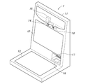
- FIG. 3 is a perspective view showing the appearance of the operator terminal 2.
- the operator terminal 2 includes a gantry 21, a first monitor 22, a second monitor 23, a front camera 24, a hand camera 25, a headset 26, and a table 27.
- the first monitor 22 is supported by the gantry 21 so as to have a predetermined height.
- the second monitor 23 includes a touch panel, and an operator can perform screen operations.
- the front camera 24 photographs the upper body including the operator's face from the front.
- the hand camera 25 photographs the hand of the operator, that is, the hand of the operator placed on the table 27 and the table 27 from above.
- the operator places a document such as a pamphlet on the table, explains the document while pointing at the hand, and this situation is photographed by the hand camera 25.
- the headset 26 includes a speaker 28 and a microphone 29.
- the speaker 28 outputs the voice uttered by the user.
- the microphone 29 collects the voice uttered by the operator.
- the operator terminal 2 is provided with a monitor 5.
- a screen of an application started on the operator terminal 2 or a PC (not shown) is displayed.
- the screen of this application is shared with the kiosk terminal 1, and the same screen is displayed on the local monitor 13 of the kiosk terminal 1 (screen sharing function).
- the monitor 5 includes a touch panel, and an operator can draw on the screen by handwriting (whiteboard function).
- the operator uses the operator terminal 2 to perform a telephone answering service that responds to the user with only voice by phone, in addition to the face-to-face answering service that responds to the user with video and voice.
- the monitor (not shown) is attached to the operator terminal 2.
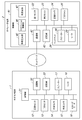
- FIG. 4 is a block diagram showing a schematic configuration of the kiosk terminal 1 and the operator terminal 2.
- the kiosk terminal 1 includes the front monitor 12, the hand monitor 13, the front camera 14, the hand camera 15, the IC card reader 16, the speaker 17, and the microphone 18 as described above.
- the kiosk terminal 1 includes a control unit 31, a communication unit 32, and a storage unit 33.
- the communication unit 32 communicates with the operator terminal 2 via a network.
- the storage unit 33 stores a program to be executed by the processor that constitutes the control unit 31.
- the control unit 31 includes a processor, and executes a predetermined process by executing a program stored in the storage unit 33 by the processor.
- connection control for connecting to the operator terminal 2 is performed, and video transmission control for transmitting and receiving in real time a user's video captured by the kiosk terminal 1 and an operator video captured by the operator terminal 2 is performed.
- the operator terminal 2 includes the first monitor 22, the second monitor 23, the front camera 24, the hand camera 25, and the headset 26 as described above.
- the operator terminal 2 includes a control unit 41, a communication unit 42, and a storage unit 43.
- the communication unit 42 communicates with the kiosk terminal 1 via the network.
- the storage unit 43 stores a program to be executed by the processor that constitutes the control unit 41.
- the storage unit 43 stores registration information of a setting information database (see FIG. 9) regarding setting information for each operator regarding calibration.
- the storage unit 43 also stores registration information in the operator database related to facial feature information for each operator in order to perform operator face authentication.
- the control unit 41 includes a video generation unit 45, a calibration control unit 46, and a face authentication unit 47.
- the control unit 41 is configured by a processor, and each unit of the control unit 41 is realized by executing a program stored in the storage unit 43 by the processor.
- the video generation unit 45 uses the front video of the operator captured by the front camera 24. An operator's front image suitable for the front monitor 12 of the kiosk terminal 1 serving as the communication partner is generated, and the operator's hand image captured by the hand camera 25 is adapted to the hand monitor 13 of the kiosk terminal 1 serving as the communication partner. An operator's hand image is generated. In the video generation unit 45, predetermined processing (cutout or the like) is performed on the operator's front video and hand video.
- the calibration control unit 46 displays a calibration operation screen (see FIGS. 7 and 8) on the second monitor 23, sets parameters related to calibration according to the screen operation of the operator, and sets the parameters. Register as setting information in the setting information database. In the present embodiment, zoom magnifications of the front camera 24 and the hand camera 25 are set as parameters relating to calibration.
- the calibration control unit 46 causes the operator to perform an operation of selecting the type of the kiosk terminal that is the communication partner on the calibration operation screen, and acquires the type of the kiosk terminal that is the communication partner.
- the operator performs an operation of inputting the specification of the kiosk terminal as the communication partner, and acquires the specification of the kiosk terminal as the communication partner.
- the calibration control unit 46 acquires the operator ID of the operator who operates the operator terminal 2, acquires the setting information of the corresponding operator from the setting information database, and reflects the setting information on the calibration operation screen. Process.
- the operator is seated in the kiosk terminal 1 in order to display a front image of the operator so that the line of sight matches between the user and the operator. It is necessary to adjust the height of the chair.
- the face authentication unit 47 verifies whether the operator who operates the operator terminal 2 is a person registered in the operator database. Specifically, a human face is detected from the front image of the operator photographed by the front camera 24, feature information of the detected face is extracted, and the feature information and the face for each operator registered in the operator database are extracted. Compared with feature information of. Here, if the face authentication is successful, the corresponding operator ID is acquired from the operator database. Note that whether or not to enable face authentication can be set in advance.
- the operator ID of the operator who uses the operator terminal 2 can be acquired by performing face authentication for the operator who uses the operator terminal 2, but in addition to this, the operator ID is input to the operator.
- the operator ID may be acquired by reading an IC card possessed by the operator with a reader.
- control unit 41 performs connection control for connecting to the kiosk terminal 1 and also transmits and receives in real time a user's video captured by the kiosk terminal 1 and an operator video captured by the operator terminal 2. Perform video transmission control.
- the operator terminal 2 may be provided with a scanner that reads a document on hand.
- an IC card reader may be provided in the operator terminal 2 in order to authenticate that the person to be operated is an authorized operator.
- the kiosk terminal 1 may be provided with a printer that prints out documents transmitted from the operator terminal 2 or information displayed on the screen.
- the second monitor 23 may be configured by a tablet PC, that is, the control unit 41, the communication unit 42, and the storage unit 43 may be housed in the housing of the second monitor 23.
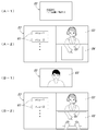
- FIG. 5 is an explanatory diagram showing a screen displayed on the kiosk terminal.
- the front monitor 12 operates as a digital signage during standby (before connection to the operator terminal 2). As shown in FIG. Content videos related to advertisements and facilities are displayed.
- a menu screen (operation screen) is displayed on the local monitor 13.
- various operation buttons 51 corresponding to the menu items are displayed.
- a call button 52 is displayed on this menu screen.
- the control unit 31 automatically starts the menu screen when the user in front of the kiosk terminal 1 is detected by a human sensor or the like, and the menu screen is displayed when the kiosk terminal 1 is not used for a predetermined time. Can be shifted to a non-display state.
- the video data of the content stored in advance in the storage unit 33 may be read and the video of the content may be played back.
- the memory card storing the video data may be used. You may make it mount
- the kiosk terminal 1 is connected to the operator terminal 2, as shown in FIG. 5 (B-1), the front image 53 of the operator photographed by the front camera 24 of the operator terminal 2 is displayed on the front monitor 12.
- the operator's hand image 54 photographed by the hand camera 25 of the operator terminal 2 is displayed on the hand monitor 13.
- the front monitor 12 displays the operator's front video 53 so that the line of sight matches between the user and the operator
- the hand monitor 13 displays the operator so that the height of the hand matches between the user and the operator. Is displayed. As a result, it is possible to realize a sense of reality that the user is facing the operator over the counter.
- the operator's hand image 54 displayed on the hand monitor 13 shows the situation that the operator is explaining while pointing to a document such as a pamphlet, and the user and the operator can interact while pointing to each other. it can.
- the application screen can be displayed on the local monitor 13 by the operation of the operator.
- the screen of this application is shared with the operator terminal 2, and the same screen is displayed on the operator terminal 2 (screen sharing function).
- the user can draw on the screen by handwriting (whiteboard function).
- the front monitor 12 may display the front image of the operator with the operator background masked.
- FIG. 6 is an explanatory diagram showing a screen displayed on the operator terminal.
- a standby screen is displayed on the first monitor 22, and when the call button 52 (see FIG. 5 (A-2)) is operated on the kiosk terminal 1, the operation terminal 2 is shown in FIG. 6 (A-1). As shown, the incoming call screen is displayed. On this incoming call screen, information (installation location, terminal name, etc.) regarding the kiosk terminal 1 that is the connection partner is displayed.
- an operation screen is displayed on the second monitor 23 as shown in FIG. 6 (A-2).
- operation buttons 61 corresponding to various menu items for controlling the operator terminal 2 and giving instructions to the kiosk terminal 1 are displayed.
- a front image 53 of the operator photographed by the front camera 24 of the operator terminal 2 and a hand image 54 of the operator photographed by the hand camera 25 of the operator terminal 2 are displayed.
- the operator's front image 53 and hand image 54 are the same as those displayed on the kiosk terminal 1.
- the operator's hand video 54 can be switched between the original state and the upside down state.
- the front image 62 of the user captured by the front camera 14 of the kiosk terminal 1 is displayed on the first monitor 22. Is done.
- the 1st monitor 22 is supported by the mount frame 21 so that it may become predetermined
- the operation button 61 is displayed on the second monitor 23 as in the standby mode.
- the operator's front image 53 is displayed on the second monitor 23 as in the standby mode.
- the operator's front image 53 can be switched to the operator's hand image.
- the second monitor 23 displays a user's hand image 63 captured by the hand camera 15 of the kiosk terminal 1 in a state where the operator's hand image is displayed. Note that the user's hand video 63 can be switched between the original state and the upside down state.
- the user's hand image 63 displayed on the second monitor 23 shows a user's hand pointing to a document such as a pamphlet displayed on the screen on the hand monitor 13 of the kiosk terminal 1, while the user and the operator point to each other. Can interact.
- the user's front image 62 is displayed on the first monitor 22 and the user's hand image 63 is displayed on the second monitor 23.
- the user's front image 62 and the hand image 63 are displayed. You may make it display on one monitor. In this case, it is possible to realize a sense of reality that faces the user through the counter from the operator side.
- FIG. 7 is an explanatory diagram showing the calibration operation screen in the initial state.
- FIG. 8 is an explanatory diagram showing a calibration operation screen in the confirmation state.
- an initial calibration operation screen is first displayed on the second monitor 23 of the operator terminal 2.
- a setting menu display unit 71 On this screen, a setting menu display unit 71, a front image display unit 72, a local image display unit 73, and an operation menu display unit 74 are provided.
- the setting menu display unit 71 is provided with an operator ID display unit 76, a timer set value display unit 77, a terminal type selection unit 78, and a terminal specification input unit 79.
- the operator ID display section 76 displays the operator ID.
- the timer set value display unit 77 displays the timer set value.
- the operator can select the type (type) of the kiosk terminal 1 to be a communication partner by operating the radio button.
- the kiosk terminal 1 has different sizes of the front monitor 12 and the hand monitor 13 depending on the type, and is also set horizontally (arranged with the long side in the horizontal direction) and vertically placed (arranged with the long side in the vertical direction). )
- the operator can input the specifications of the kiosk terminal that is the communication partner, specifically, the sizes of the front monitor 12 and the hand monitor 13 of the kiosk terminal 1. Accordingly, appropriate calibration can be performed even in the kiosk terminal 1 that is different from the type selectable by the terminal type selection unit 78. Note that an interval (monitor interval) between the front monitor 12 and the local monitor 13 may be input. In addition to the monitor size, the aspect ratio of the screen may be set.
- the front video display unit 72 displays a front video 53 of the operator taken by the front camera 24 of the operator terminal 2.
- a guide image 81 representing the outer shape of the upper body of the person, that is, the ⁇ shape formed by the person's head and shoulders, is displayed on the front image display unit 72.
- the operator performs a calibration operation related to the operator's front image 53 with reference to the guide image 81.
- the operator's hand image 54 photographed by the hand camera 25 of the operator terminal 2 is displayed on the hand image display unit 73.
- the hand image display unit 73 displays a guide image 82 representing the outer shape of a person's hand.
- the operator performs a calibration operation related to the operator's hand image with reference to the guide image 82.
- the operator's hand image displayed on the hand image display unit 73 may be switched between the original state and the upside down state.
- the operation menu display unit 74 is provided with a zoom magnification input unit 83.
- the zoom magnifications of the front camera 24 and the hand camera 25 can be input by operating the slider of the slide bar.
- the operator adjusts the zoom magnification of the front camera 24 so that his / her face reflected in the front image 53 displayed on the front image display unit 72 is aligned with the guide image 81.
- the operator adjusts the zoom magnification of the hand camera 25 so that his / her hand shown in the hand video 54 displayed on the hand video display unit 73 is aligned with the guide image 82.
- the height of one's face reflected in the front image 53 displayed on the front image display unit 72 may be adjusted by moving up and down the chair on which he is seated.
- the front image 53 displayed on the front image display unit 72 is enlarged or reduced, and the size of his / her face shown in the front image 53 is adjusted. can do.
- the hand image 54 displayed on the hand image display unit 73 is enlarged or reduced, and the size of his / her hand shown in the hand image 54 is adjusted. be able to.
- the operator first adjusts the position and size of his / her hand according to the guide image 82 displayed on the hand image display unit 73, and then adjusts the position and size of the hand to match the position and size of the hand.
- the height and size of his / her face may be adjusted in accordance with the guide image 81 displayed on 72.
- hand adjustment may be performed after face adjustment, or face adjustment and hand adjustment may be performed alternately.
- the operation menu display unit 74 is provided with an apply button 85, a confirmation button 86, and a decision button 87.
- the kiosk terminal Guide images 81 and 82 suitable for the type 1 and monitor size are displayed on the front image display unit 72 and the local image display unit 73.
- the setting information is updated with the input contents of the calibration operation screen.
- a kiosk terminal display unit 91 is provided on the calibration operation screen in the confirmation state.
- the setting menu display unit 71 and the operation menu display unit 74 are the same as in the initial state (see FIG. 7).
- the kiosk terminal display unit 91 displays a virtual video 92 representing a state where the operator's front video and hand video are displayed on the kiosk terminal 1.
- the type of the kiosk terminal 1 selected by the terminal type selection unit 78 and the sizes of the front monitor 12 and the hand monitor 13 input by the terminal specification input unit 79 are reflected.
- the zoom magnification input by the zoom magnification input unit 83 is reflected in the front image and the local image of the operator displayed on the front monitor 12 and the local monitor 13 displayed in the virtual image 92.
- the virtual video 92 according to the attribute (type and specification) of the connection destination kiosk terminal 1 is displayed, whether or not the operator is displayed on the kiosk terminal 1 in an appropriate state is determined.
- the operator can make an appropriate decision.
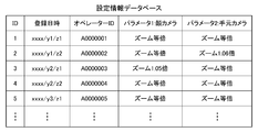
- FIG. 9 is an explanatory diagram showing the registration contents of the setting information database.
- the operator terminal 2 manages calibration setting information for each operator in the setting information database.
- this setting information database a record ID, a registration date, an operator ID, a first parameter relating to the front camera 24, a second parameter relating to the hand camera 25, and the like are registered for each event for which the setting information has been registered.
- the first parameter is the zoom magnification of the front camera 24, and the second parameter is the zoom magnification of the hand camera 25.
- setting information database setting information related to the operator is registered when the operator performs a calibration operation.
- the setting information (parameter) of the user is stored from the setting information database. And the setting information is reflected on the calibration operation screen (see FIGS. 7 and 8), so that the operator's operation can be omitted.
- FIG. 10 is a flowchart showing a calibration control procedure.
- the operator terminal 2 first determines whether or not face authentication is valid (ST101).
- face authentication is valid (Yes in ST101)
- the face authentication of the operator to be operated is performed based on the operator's front image captured by the front camera 24 (ST102).
- ST102 the face authentication of the operating operator is successful
- ST103 it is determined whether or not the face authentication of the operating operator is successful
- the operator ID is acquired from the operator database (ST104). Then, based on the operator ID, it is determined whether the operator to be operated is registered in the setting information database (ST105).
- the setting information of the corresponding operator is acquired from the setting information database (ST106). Then, a calibration operation screen (see FIGS. 7 and 8) reflecting the setting information of the operator is displayed (ST107).
- the calibration operation screen is updated in accordance with the operation (ST108).
- the operator operates the enter button Yes in ST109
- the contents input by the operator on the calibration operation screen are registered in the setting information database as operator setting information (ST110).
- step ST111 when importing operator setting information (Yes in ST111), the operator is allowed to input an operator ID, and the operator setting information is imported based on the operator ID (ST112).
- step ST107 a calibration operation screen reflecting the imported operator setting information is displayed.
- the attribute of the operator is related to gender (male, female), physique (large, standard, small), etc. Since the size of the operator's body varies depending on this attribute, The state of the displayed front image and hand image of the operator changes. Therefore, initial setting information is acquired according to the attribute of the operator. For example, in the case of a large man, the operator appears large, so the zoom magnification is set low as the initial setting information.
- calibration is performed based on initial setting information (preset information) according to the operator's attributes. It can be carried out.
- the operator when the operator has used the operator terminal 2 in the past, the operator is identified by face authentication, and calibration is automatically performed based on the setting information of the operator. It is only necessary to perform the operation of adjusting the calibration, and the calibration can be completed in a short time, and the operator can start the face-to-face business using the operator terminal 2 promptly.
- the adjustment in the height direction of the operator can be performed by using a table with an electric lifting mechanism in addition to the adjustment by raising and lowering the chair. Information on the height direction of the operator may be registered as operator setting information.
- the embodiment has been described as an example of the technique disclosed in the present application.
- the technology in the present disclosure is not limited to this, and can be applied to embodiments in which changes, replacements, additions, omissions, and the like have been performed.
- the operator terminal and the calibration method according to the present invention can be used for calibration when performing calibration related to an image so that the operator can display an image reflected in an appropriate state on the kiosk terminal even when the operator is changed. Supporting the operator's work and having the effect of performing calibration efficiently, both the video of the user who operates the kiosk terminal and the video of the operator who operates the own device between the kiosk terminal This is useful as a calibration method for adjusting an operator image to be displayed on a kiosk terminal in an operator terminal that communicates with the operator terminal.
Landscapes
- Engineering & Computer Science (AREA)
- Multimedia (AREA)
- Signal Processing (AREA)
- Theoretical Computer Science (AREA)
- General Physics & Mathematics (AREA)
- Physics & Mathematics (AREA)
- Computer Vision & Pattern Recognition (AREA)
- Human Computer Interaction (AREA)
- Health & Medical Sciences (AREA)
- Social Psychology (AREA)
- Psychiatry (AREA)
- General Health & Medical Sciences (AREA)
- User Interface Of Digital Computer (AREA)
- Telephone Set Structure (AREA)
- Two-Way Televisions, Distribution Of Moving Picture Or The Like (AREA)
Abstract
【課題】映像に関するキャリブレーションに係るオペレータの作業を支援して、キャリブレーションを効率よく行うことができるようにする。 【解決手段】正面カメラによりオペレータの顔を含む上半身を正面から撮影した正面映像53と、手元カメラによりオペレータの手元を上方から撮影した手元映像54と、をモニタに表示し、同時に、正面映像に映るオペレータの上半身の適切な状態、および手元映像に映るオペレータの手の適切な状態を案内する案内情報として、正面映像上に、オペレータの上半身の適切な状態を表すガイド画像81をモニタに表示し、手元映像上に、オペレータの手の適切な状態を表すガイド画像82をモニタに表示し、ガイド画像81,82に従って行われるオペレータの操作入力に応じて、正面映像および手元映像を調整する。
Description
本発明は、キオスク端末を操作するユーザの映像と自装置を操作するオペレータの映像とを、キオスク端末との間で双方向に通信するオペレータ端末、及びオペレータ端末において、キオスク端末に表示させるオペレータの映像を調整するキャリブレーション方法に関するものである。
近年、遠隔地にいる複数の人物をそれぞれ撮影した映像を双方向に通信する双方向映像通信システムが普及している。一方、各種の情報を提供する案内業務や金融機関などの窓口業務などのサービスを、人に代わって提供するキオスク端末が普及しており、このようなキオスク端末と、ユーザに応対するオペレータが操作するオペレータ端末とで、双方向映像通信システムを構築すると、ユーザにオペレータが対面して応対することができるため、キオスク端末によるサービスの品質を向上させることができる。
このような双方向映像通信システムでは、キオスク端末において、ユーザがオペレータと対面しているような臨場感を得るため、キオスク端末に表示される映像にオペレータが適切な状態で映るように、映像に関するキャリブレーションを行うことが望まれる。このような映像に関するキャリブレーションに関する技術として、従来、双方向映像通信システムにおいて、対話者同士の視線が一致するように、カメラの位置を制御する技術が知られている(特許文献1参照)。
さて、双方向映像通信システムでは、実際に対面しているような臨場感を得るには、前記従来の技術のように、対話者同士の視線を一致させることが必要であるが、このような視線の一致以外にも、映像に映る人物の大きさなど、人物が適切な状態で映るように映像を最適化する必要がある。また、コールセンターなどでは、複数のオペレータが1台のオペレータ端末を交代で使用するため、オペレータが交代した際に、映像を最適化するキャリブレーションを効率よく行うことで、オペレータ端末を用いた業務を速やかに開始できるようにすることが望まれる。
しかしながら、前記従来の技術では、視線の一致以外のキャリブレーションに関しては何ら考慮されていないため、人物が適切な状態で映るように映像を最適化するキャリブレーションを効率よく行うことができないという問題があった。
そこで、本発明は、オペレータの交代があった場合でも、オペレータが適切な状態で映る映像をキオスク端末に表示できるように、映像に関するキャリブレーションを行う場合に、キャリブレーションに係るオペレータの作業を支援して、キャリブレーションを効率よく行うことができるオペレータ端末及びそのキャリブレーション方法を提供することを主な目的とする。
本発明のオペレータ端末は、キオスク端末を操作するユーザの映像と自装置を操作するオペレータの映像とを、前記キオスク端末との間で双方向に通信するオペレータ端末であって、前記キオスク端末と通信を行う通信部と、オペレータの顔を含む上半身を正面から撮影する正面カメラと、オペレータの手元を上方から撮影する手元カメラと、前記正面カメラで撮影した正面映像および前記手元カメラで撮影した手元映像を前記通信部から前記キオスク端末に送信して、前記正面映像および前記手元映像をそれぞれ前記キオスク端末に設けられた正面モニタおよび手元モニタに表示させる制御部と、前記正面映像および前記手元映像を調整するキャリブレーションの状況を表示するモニタと、を備え、前記制御部は、前記正面映像に映るオペレータの上半身の適切な状態、および前記手元映像に映るオペレータの手の適切な状態を案内する案内情報を前記モニタに表示し、前記案内情報に従って行われるオペレータの操作入力に応じて、前記正面映像および前記手元映像を調整する構成とする。
また、本発明のキャリブレーション方法は、キオスク端末を操作するユーザの映像と自装置を操作するオペレータの映像とを、前記キオスク端末との間で双方向に通信するオペレータ端末において、前記キオスク端末に表示させる前記オペレータの映像を調整するキャリブレーション方法であって、オペレータの顔を含む上半身を正面から撮影する正面カメラで取得した正面映像と、オペレータの手元を上方から撮影する手元カメラで取得した手元映像と、をモニタに表示し、同時に、前記正面映像に映るオペレータの上半身の適切な状態、および前記手元映像に映るオペレータの手の適切な状態を案内する案内情報を前記モニタに表示し、前記案内情報に従って行われるオペレータの操作入力に応じて、前記正面映像および前記手元映像を調整する構成とする。
本発明によれば、オペレータが案内情報にしたがって調整作業を行うことで、オペレータの上半身が適切な状態で映る正面映像、およびオペレータの手が適切な状態で映る手元映像を取得することができる。これにより、キャリブレーションを効率よく行うことができる。
前記課題を解決するためになされた第1の発明は、キオスク端末を操作するユーザの映像と自装置を操作するオペレータの映像とを、前記キオスク端末との間で双方向に通信するオペレータ端末であって、前記キオスク端末と通信を行う通信部と、オペレータの顔を含む上半身を正面から撮影する正面カメラと、オペレータの手元を上方から撮影する手元カメラと、前記正面カメラで撮影した正面映像および前記手元カメラで撮影した手元映像を前記通信部から前記キオスク端末に送信して、前記正面映像および前記手元映像をそれぞれ前記キオスク端末に設けられた正面モニタおよび手元モニタに表示させる制御部と、前記正面映像および前記手元映像を調整するキャリブレーションの状況を表示するモニタと、を備え、前記制御部は、前記正面映像に映るオペレータの上半身の適切な状態、および前記手元映像に映るオペレータの手の適切な状態を案内する案内情報を前記モニタに表示し、前記案内情報に従って行われるオペレータの操作入力に応じて、前記正面映像および前記手元映像を調整する構成とする。
これによると、オペレータが案内情報にしたがって調整作業を行うことで、オペレータの上半身が適切な状態で映る正面映像、およびオペレータの手が適切な状態で映る手元映像を取得することができる。これにより、キャリブレーションを効率よく行うことができる。
また、第2の発明は、前記制御部は、前記案内情報として、前記正面映像上に、オペレータの上半身の適切な状態を表すガイド画像を表示し、前記手元映像上に、オペレータの手の適切な状態を表すガイド画像を表示する構成とする。
これによると、ガイド画像を基準にして、正面映像に映るオペレータの上半身の状態を調整し、また、手元映像に映るオペレータの手の状態を調整すればよいため、オペレータが調整作業を効率よく行うことができる。
また、第3の発明は、前記制御部は、前記正面映像および前記手元映像が前記キオスク端末に表示された状態を表す仮想映像を前記モニタに表示する構成とする。
これによると、正面映像および手元映像をキオスク端末に実際に表示した場合に、正面映像に映るオペレータの上半身と、手元映像に映るオペレータの手とが、適切なバランスで表示されるか否かを、オペレータが適切に判断することができる。
また、第4の発明は、前記制御部は、通信相手となる前記キオスク端末の属性を入力するオペレータの操作入力に応じて、入力された前記キオスク端末の属性に基づいて、通信相手となる前記キオスク端末の前記正面モニタおよび前記手元モニタにそれぞれ適合するように前記正面映像および前記手元映像を調整する構成とする。
これによると、通信相手となるキオスク端末のモニタに適合した正面映像および手元映像を取得することができる。
また、第5の発明は、前記制御部は、前記キオスク端末の属性として、前記キオスク端末の種別および仕様の少なくともいずれかをオペレータに入力させる画面を前記モニタに表示する構成とする。
これによると、通信相手となるキオスク端末のモニタに適合した正面映像および手元映像を取得することができる。
また、第6の発明は、前記制御部は、キャリブレーションが終了すると、そのキャリブレーションで取得した設定情報をオペレータに対応付けて登録し、オペレータが自装置の使用を開始する際に、自装置を使用するオペレータを識別して、そのオペレータに対応する前記設定情報に基づいて、前記正面映像および前記手元映像を調整する構成とする。
これによると、オペレータが最初にオペレータ端末を使用する際に、キャリブレーションを一度行うと、次回からは、設定情報に基づいてキャリブレーションを行うため、キャリブレーションを短時間に終了して、オペレータがオペレータ端末でユーザに応対する業務を速やかに開始することができる。
また、第7の発明は、前記制御部は、ズーム倍率を指定するオペレータの操作入力に応じて、前記正面映像および前記手元映像に対して拡大および縮小の処理を行う構成とする。
これによると、オペレータが適切な状態で映る映像を取得することができる。
また、第8の発明は、キオスク端末を操作するユーザの映像と自装置を操作するオペレータの映像とを、前記キオスク端末との間で双方向に通信するオペレータ端末において、前記キオスク端末に表示させる前記オペレータの映像を調整するキャリブレーション方法であって、オペレータの顔を含む上半身を正面から撮影する正面カメラで取得した正面映像と、オペレータの手元を上方から撮影する手元カメラで取得した手元映像と、をモニタに表示し、同時に、前記正面映像に映るオペレータの上半身の適切な状態、および前記手元映像に映るオペレータの手の適切な状態を案内する案内情報を前記モニタに表示し、前記案内情報に従って行われるオペレータの操作入力に応じて、前記正面映像および前記手元映像を調整する構成とする。
これによると、第1の発明と同様に、キャリブレーションを効率よく行うことができる。
以下、本発明の実施の形態を、図面を参照しながら説明する。
図1は、本実施形態に係る双方向映像通信システムの全体構成図である。
この双方向映像通信システムは、キオスク端末1と、オペレータ端末2と、を備えている。キオスク端末1とオペレータ端末2とは、インターネットやVPN(Virtual Private Network)やイントラネットなどのネットワークを介して接続される。
キオスク端末1は、各種の施設に設置され、ユーザが操作するものであり、ユーザを撮影した映像をオペレータ端末2に送信し、オペレータ端末2から受信したオペレータの映像を表示する。
オペレータ端末2は、コールセンターなど、ユーザに応対するオペレータが常駐する施設に設置され、オペレータが操作するものであり、オペレータを撮影した映像をキオスク端末1に送信し、キオスク端末1から受信したユーザの映像を表示する。
なお、キオスク端末1では、様々なサービスを提供することができる。例えば、キオスク端末1を空港などの交通施設のロビーなどに設置することで、周辺の観光地の案内や、施設内のフロアの案内や、周辺の宿泊施設の案内などのサービスを提供することができる。また、キオスク端末1を銀行などの金融機関の店舗に設置することで、窓口などで行われる各種のサービス、例えば、口座開設や金融取引やローン契約の相談などのサービスを提供することができる。また、キオスク端末1をホテルなどの宿泊施設のフロントなどに設置することで、係員(コンシェルジュ)が行う各種の案内サービスを提供することができる。また、マンションなどの共同住宅の玄関ロビーなどに設置することで、管理人が行う各種のサービスを提供することができる。
このようにキオスク端末1では、各種のサービスを担当者に代わって常時提供することができるため、サービスの品質を向上させることができ、また、オペレータが複数の施設を掛け持ちで担当することができるため、人員削減を図ることができる。
また、キオスク端末1とオペレータ端末2との間では、ユーザの映像とオペレータの映像とを双方向に通信するが、この他に、キオスク端末1やオペレータ端末2において、ユーザやオペレータが操作した内容に関する操作情報、ユーザやオペレータが入力したテキスト情報などが双方向に通信される。
特に、機密情報、例えば、ユーザの氏名や住所などの個人情報や、金融機関の口座番号などの情報がやり取りされる場合がある。このような機密情報の通信については、サービス提供者が、セキュリティを高度に確保した専用のネットワークを既に運用しているため、機密情報を含む映像以外の情報は既存のネットワークで通信し、これとは別のネットワークで映像を通信するようにしてもよい。これにより、セキュリティを確保するとともに、通信量が大きい映像を別のネットワークで通信することで、既存のネットワークの負荷が増大しないようにすることができる。
次に、キオスク端末1について説明する。図2は、キオスク端末1の外観を示す斜視図である。
キオスク端末1は、筐体11と、正面モニタ12と、手元モニタ13と、正面カメラ14と、手元カメラ15と、ICカードリーダ16と、スピーカー17と、マイク18と、を備えている。
正面モニタ12は、画面を前向きにした状態で配置され、手元モニタ13は、画面を上向きにした状態で配置されている。また、手元モニタ13はタッチパネルを備えており、ユーザが画面操作を行うことができる。
正面カメラ14は、ユーザの顔を含む上半身を正面から撮影する。手元カメラ15は、ユーザの手元、すなわち、手元モニタ13上に置いたユーザの手と手元モニタ13の画面とを上方から撮影する。ユーザは、手元モニタ13の画面を手先で指し示す動作を行い、この状況が手元カメラ15で撮影される。
ICカードリーダ16は、ユーザが所持するICカードを読み取る。
スピーカー17は、オペレータが発した音声を出力する。マイク18は、ユーザが発した音声を収音する。
このように構成されたキオスク端末1は、カウンタなどの台に載置され、ユーザが椅子に座った状態で、あるいは、立ったままの状態でキオスク端末1を操作する。
次に、オペレータ端末2について説明する。図3は、オペレータ端末2の外観を示す斜視図である。
オペレータ端末2は、架台21と、第1モニタ22と、第2モニタ23と、正面カメラ24と、手元カメラ25と、ヘッドセット26と、テーブル27と、を備えている。
第1モニタ22は、所定の高さとなるように架台21に支持されている。第2モニタ23は、タッチパネルを備えており、オペレータが画面操作を行うことができる。
正面カメラ24は、オペレータの顔を含む上半身を正面から撮影する。手元カメラ25は、オペレータの手元、すなわち、テーブル27上に置いたオペレータの手とテーブル27とを上方から撮影する。オペレータは、テーブルにパンフレットなどの書類を置いて、書類を手先で指し示しながら書類を説明し、この状況が手元カメラ25で撮影される。
ヘッドセット26は、スピーカー28と、マイク29と、を備えている。スピーカー28は、ユーザが発した音声を出力する。マイク29は、オペレータが発した音声を収音する。
また、オペレータ端末2には、モニタ5が併設される。このモニタ5には、オペレータ端末2、または、図示しないPCで起動させたアプリケーションの画面が表示される。このアプリケーションの画面はキオスク端末1と共有され、同一の画面がキオスク端末1の手元モニタ13に表示される(画面共有機能)。また、モニタ5はタッチパネルを備えており、オペレータが手書きで画面上に描画することができる(ホワイトボード機能)。
なお、コールセンターでは、オペレータが、オペレータ端末2を使用して映像と音声でユーザに応対する対面応対業務とは別に、電話による音声のみでユーザに応対する電話応対業務を行うため、電話応対業務用のモニタ(図示せず)がオペレータ端末2に併設される。
次に、キオスク端末1およびオペレータ端末2の概略構成について説明する。図4は、キオスク端末1およびオペレータ端末2の概略構成を示すブロック図である。
キオスク端末1は、前記のように、正面モニタ12と、手元モニタ13と、正面カメラ14と、手元カメラ15と、ICカードリーダ16と、スピーカー17と、マイク18と、を備えている。また、キオスク端末1は、制御部31と、通信部32と、記憶部33と、を備えている。
通信部32は、ネットワークを介してオペレータ端末2と通信を行う。
記憶部33は、制御部31を構成するプロセッサで実行されるプログラムを記憶する。
制御部31は、プロセッサで構成され、記憶部33に記憶されたプログラムをプロセッサで実行することで、所定の処理を実行する。本実施形態では、オペレータ端末2に接続する接続制御を行い、また、キオスク端末1で撮影したユーザの映像と、オペレータ端末2で撮影したオペレータの映像と、をリアルタイムで送受信する映像伝送制御などを行う。
オペレータ端末2は、前記のように、第1モニタ22と、第2モニタ23と、正面カメラ24と、手元カメラ25と、ヘッドセット26と、を備えている。また、オペレータ端末2は、制御部41と、通信部42と、記憶部43と、を備えている。
通信部42は、ネットワークを介してキオスク端末1と通信を行う。
記憶部43は、制御部41を構成するプロセッサで実行されるプログラムを記憶する。また、記憶部43は、キャリブレーションに関するオペレータごとの設定情報に関する設定情報データベース(図9参照)の登録情報を記憶する。また、記憶部43は、オペレータの顔認証を行うために、オペレータごとの顔の特徴情報に関するオペレータデータベースの登録情報を記憶する。
制御部41は、映像生成部45と、キャリブレーション制御部46と、顔認証部47と、を備えている。この制御部41は、プロセッサで構成され、制御部41の各部は、記憶部43に記憶されたプログラムをプロセッサで実行することで実現される。
映像生成部45は、キャリブレーション制御部46で設定された設定情報と、通信相手となるキオスク端末1の属性(種別や仕様)とに基づいて、正面カメラ24で撮影したオペレータの正面映像から、通信相手となるキオスク端末1の正面モニタ12に適合したオペレータの正面映像を生成し、また、手元カメラ25で撮影したオペレータの手元映像から、通信相手となるキオスク端末1の手元モニタ13に適合したオペレータの手元映像を生成する。この映像生成部45では、オペレータの正面映像および手元映像に対して所定の加工(切り出しなど)が行われる。
キャリブレーション制御部46は、キャリブレーション操作画面(図7,図8参照)を第2モニタ23に表示して、オペレータの画面操作に応じて、キャリブレーションに係るパラメータを設定して、そのパラメータを設定情報として設定情報データベースに登録する。本実施形態では、キャリブレーションに係るパラメータとして、正面カメラ24および手元カメラ25のズーム倍率を設定する。
また、キャリブレーション制御部46は、キャリブレーション操作画面において、通信相手となるキオスク端末の種別を選択する操作をオペレータに行わせて、通信相手となるキオスク端末の種別を取得する。また、キャリブレーション操作画面において、通信相手となるキオスク端末の仕様を入力する操作をオペレータに行わせて、通信相手となるキオスク端末の仕様を取得する。
また、キャリブレーション制御部46は、オペレータ端末2を操作するオペレータのオペレータIDを取得して、該当するオペレータの設定情報を設定情報データベースから取得して、その設定情報をキャリブレーション操作画面に反映する処理を行う。
なお、キャリブレーションの際には、ズーム倍率を調整する他に、キオスク端末1において、ユーザとオペレータとで目線の高さが一致するように、オペレータの正面映像を表示するため、オペレータが着座する椅子の高さを調整する必要がある。
顔認証部47は、キャリブレーションを開始する際に、オペレータ端末2を操作するオペレータがオペレータデータベースに登録された人物が否かを検証する。具体的には、正面カメラ24で撮影したオペレータの正面映像から人物の顔を検出して、検出した顔の特徴情報を抽出して、その特徴情報と、オペレータデータベースに登録されたオペレータごとの顔の特徴情報とを比較照合する。ここで、顔認証が成功すると、該当するオペレータIDをオペレータデータベースから取得する。なお、顔認証を有効とするか否かを予め設定することができる。
なお、本実施形態では、オペレータ端末2を使用するオペレータについて顔認証を行うことにより、オペレータ端末2を使用するオペレータのオペレータIDを取得することができるが、この他に、オペレータにオペレータIDを入力させ、また、オペレータが所持するICカードをリーダで読み取ることにより、オペレータIDを取得するようにしてもよい。
また、制御部41は、この他に、キオスク端末1に接続する接続制御を行い、また、キオスク端末1で撮影したユーザの映像と、オペレータ端末2で撮影したオペレータの映像と、をリアルタイムで送受信する映像伝送制御などを行う。
なお、オペレータ端末2に、手持ちの書類を読み取るスキャナを設けるようにしてもよい。また、オペレータ端末2に、操作する人物が正規のオペレータであることの認証を行うために、ICカードリーダを設けるようにしてもよい。また、キオスク端末1に、オペレータ端末2から送信された書類や画面表示された情報などを印刷出力するプリンタを設けるようにしてもよい。
また、第2モニタ23をタブレットPCで構成する、すなわち、第2モニタ23の筐体内に、制御部41、通信部42および記憶部43を収容した構成としてもよい。
次に、キオスク端末1に表示される画面について説明する。図5は、キオスク端末に表示される画面を示す説明図である。
キオスク端末1では、スタンバイ時(オペレータ端末2に接続する前)には、正面モニタ12がデジタルサイネージとして動作し、図5(A-1)に示すように、正面モニタ12に、お薦めプランなどの広告や施設などの案内に関するコンテンツの映像が表示される。
また、スタンバイ時には、図5(A-2)に示すように、手元モニタ13に、メニュー画面(操作画面)が表示される。このメニュー画面には、メニュー項目に対応した各種の操作ボタン51が表示されている。また、このメニュー画面には、通話ボタン52が表示されている。この通話ボタン52を操作すると、キオスク端末1がオペレータ端末2に接続され、オペレータとの対話を開始することができる。なお、制御部31は、人感センサなどによりキオスク端末1の前のユーザを感知すると、メニュー画面を自動で立ち上げるようにし、また、キオスク端末1の利用がない状態が所定時間継続するとメニュー画面を非表示状態に移行させることができる。
なお、正面モニタ12をデジタルサイネージとして動作させる際には、予め記憶部33に記憶されたコンテンツの映像データを読み出して、コンテンツの映像を再生すればよいが、映像データが格納されたメモリカードをキオスク端末1に装着したり、ネットワークを介して配信サーバからキオスク端末1に映像データを配信したりするようにしてもよい。
一方、キオスク端末1がオペレータ端末2に接続されると、図5(B-1)に示すように、正面モニタ12に、オペレータ端末2の正面カメラ24で撮影したオペレータの正面映像53が表示され、同時に、図5(B-2)に示すように、手元モニタ13に、オペレータ端末2の手元カメラ25で撮影したオペレータの手元映像54が表示される。
正面モニタ12では、ユーザとオペレータとで目線の高さが一致するように、オペレータの正面映像53が表示され、手元モニタ13では、ユーザとオペレータとで手元の高さが一致するように、オペレータの手元映像54が表示される。これにより、ユーザがオペレータとカウンタ越しで向き合っているような臨場感を実現することができる。
また、手元モニタ13に表示されるオペレータの手元映像54には、オペレータがパンフレットなどの書類を手先で指し示しながら説明している状況が映り、ユーザとオペレータとで互いに書類を指し示しながら対話することができる。
また、オペレータの操作により、手元モニタ13に、アプリケーションの画面を表示させることができる。このアプリケーションの画面はオペレータ端末2と共有され、同一の画面がオペレータ端末2に表示される(画面共有機能)。また、アプリケーションの画面では、ユーザが手書きで画面上に描画することができる(ホワイトボード機能)。
なお、正面モニタ12では、オペレータの背景がマスキングされた状態でオペレータの正面映像が表示されるようにしてもよい。
次に、オペレータ端末2に表示される画面について説明する。図6は、オペレータ端末に表示される画面を示す説明図である。
オペレータ端末2では、スタンバイ時には、第1モニタ22に、待ち受け画面が表示され、キオスク端末1で通話ボタン52(図5(A-2)参照)を操作すると、図6(A-1)に示すように、着信画面が表示される。この着信画面には、接続相手となるキオスク端末1に関する情報(設置場所や端末名称など)が表示される。
また、スタンバイ時には、図6(A-2)に示すように、第2モニタ23に、操作画面が表示される。この操作画面には、オペレータ端末2の制御やキオスク端末1に対する指示などを行うための各種のメニュー項目に対応した操作ボタン61が表示される。
また、第2モニタ23には、オペレータ端末2の正面カメラ24で撮影したオペレータの正面映像53と、オペレータ端末2の手元カメラ25で撮影したオペレータの手元映像54とが表示される。このオペレータの正面映像53および手元映像54は、キオスク端末1に表示されるものと同じものである。なお、オペレータの手元映像54は、元の状態と上下反転した状態とを切り替えることができる。
一方、オペレータ端末2がキオスク端末1に接続されると、図6(B-1)に示すように、第1モニタ22に、キオスク端末1の正面カメラ14で撮影したユーザの正面映像62が表示される。なお、第1モニタ22は、所定の高さとなるように架台21に支持されており(図3参照)、これにより、オペレータとユーザとで視線を一致させることができる。
また、図6(B-2)に示すように、第2モニタ23に、スタンバイ時と同様に、操作ボタン61が表示される。また、第2モニタ23には、スタンバイ時と同様に、オペレータの正面映像53が表示される。このオペレータの正面映像53は、オペレータの手元映像と切り替えることができる。また、第2モニタ23には、オペレータの手元映像が表示された状態でキオスク端末1の手元カメラ15で撮影したユーザの手元映像63が表示される。なお、ユーザの手元映像63は、元の状態と上下反転した状態とを切り替えることができる。
第2モニタ23に表示されるユーザの手元映像63には、キオスク端末1の手元モニタ13上で画面に映るパンフレットなどの書類を指し示すユーザの手先が映り、ユーザとオペレータとで互いに書類を指し示しながら対話することができる。
なお、本実施形態では、ユーザの正面映像62を第1モニタ22に表示し、ユーザの手元映像63を第2モニタ23に表示するようにしたが、ユーザの正面映像62と手元映像63とを1つのモニタに表示するようにしてもよい。この場合、オペレータ側からもユーザとカウンタ越しで向き合っているような臨場感を実現することができる。
次に、キャリブレーションの際にオペレータ端末2に表示される画面について説明する。図7は、初期状態のキャリブレーション操作画面を示す説明図である。図8は、確認状態のキャリブレーション操作画面を示す説明図である。
図7に示すように、キャリブレーションの際には、まず、オペレータ端末2の第2モニタ23に、初期状態のキャリブレーション操作画面が表示される。この画面には、設定メニュー表示部71と、正面映像表示部72と、手元映像表示部73と、操作メニュー表示部74と、が設けられている。
設定メニュー表示部71には、オペレータID表示部76と、タイマ設定値表示部77と、端末タイプ選択部78と、端末仕様入力部79と、が設けられている。
オペレータID表示部76には、オペレータIDが表示される。タイマ設定値表示部77には、タイマ設定値が表示される。
端末タイプ選択部78では、ラジオボタンを操作することで、通信相手となるキオスク端末1のタイプ(種別)をオペレータが選択することができる。なお、キオスク端末1は、タイプに応じて、正面モニタ12および手元モニタ13のサイズが異なり、また、横置き(長辺を横方向とした配置)と縦置き(長辺を縦方向とした配置)とがある。
端末仕様入力部79では、通信相手となるキオスク端末の仕様、具体的には、キオスク端末1の正面モニタ12および手元モニタ13のサイズをオペレータが入力することができる。これにより、端末タイプ選択部78で選択可能なタイプと異なるキオスク端末1でも、適切なキャリブレーションを行うことができる。なお、正面モニタ12と手元モニタ13との間隔(モニタ間隔)を入力できるようにしてもよい。また、モニタサイズに加え、画面のアスペクト比を設定できるようにしてもよい。
正面映像表示部72には、オペレータ端末2の正面カメラ24で撮影したオペレータの正面映像53が表示される。また、正面映像表示部72には、人物の上半身の外形、すなわち、人物の頭および肩により形成されるΩ形状を表すガイド画像81が表示される。オペレータは、このガイド画像81を基準にして、オペレータの正面映像53に関するキャリブレーションの操作を行う。
手元映像表示部73には、オペレータ端末2の手元カメラ25で撮影したオペレータの手元映像54が表示される。また、手元映像表示部73には、人物の手の外形を表すガイド画像82が表示される。オペレータは、このガイド画像82を基準にして、オペレータの手元映像に関するキャリブレーションの操作を行う。なお、手元映像表示部73に表示されるオペレータの手元映像は、元の状態と上下反転した状態とを切り替えることができるようにしてもよい。
操作メニュー表示部74には、ズーム倍率入力部83が設けられている。このズーム倍率入力部83では、スライドバーのスライダを操作することで、正面カメラ24および手元カメラ25のズーム倍率を入力することができる。オペレータは、正面映像表示部72に表示される正面映像53に映る自分の顔がガイド画像81に整合するように、正面カメラ24のズーム倍率を調整する。また、オペレータは、手元映像表示部73に表示される手元映像54に映る自分の手がガイド画像82に整合するように、手元カメラ25のズーム倍率を調整する。
なお、正面映像表示部72に表示される正面映像53に映る自分の顔の高さは、自分が着座する椅子を昇降することで調整すればよい。
このとき、正面カメラ24のズーム倍率を変更する操作をオペレータが行うと、正面映像表示部72に表示される正面映像53が拡大または縮小し、正面映像53に映る自分の顔の大きさを調整することができる。また、手元カメラ25のズーム倍率を変更する操作をオペレータが行うと、手元映像表示部73に表示される手元映像54が拡大または縮小し、手元映像54に映る自分の手の大きさを調整することができる。
なお、オペレータは、まず、手元映像表示部73に表示されるガイド画像82に従って、自分の手の位置および大きさを調整し、ついで、手の位置および大きさに合わせるように、正面映像表示部72に表示されるガイド画像81に従って、自分の顔の高さおよび大きさを調整するとよい。なお、これとは逆に、顔の調整を行った上で手の調整を行うようにしてもよく、また、顔の調整と手の調整とを交互に行うようにしてもよい。
また、操作メニュー表示部74には、適用ボタン85と、確認ボタン86と、決定ボタン87と、が設けられている。
端末タイプ選択部78でキオスク端末1のタイプを選択し、また、端末仕様入力部79でキオスク端末1の正面モニタ12および手元モニタ13のサイズを入力した上で適用ボタン85を操作すると、キオスク端末1のタイプやモニタサイズに適合したガイド画像81,82が正面映像表示部72および手元映像表示部73に表示される。
確認ボタン86を操作すると、確認状態のキャリブレーション操作画面(図8参照)に遷移する。
決定ボタン87を操作すると、キャリブレーション操作画面の入力内容で設定情報が更新される。
図8に示すように、確認状態のキャリブレーション操作画面には、キオスク端末表示部91が設けられている。設定メニュー表示部71および操作メニュー表示部74は、初期状態(図7参照)と同様である。
キオスク端末表示部91には、オペレータの正面映像および手元映像がキオスク端末1に表示された状態を表す仮想映像92が表示される。この仮想映像92に映るキオスク端末1では、端末タイプ選択部78で選択したキオスク端末1のタイプや、端末仕様入力部79で入力した正面モニタ12および手元モニタ13のサイズが反映されている。また、仮想映像92に映る正面モニタ12および手元モニタ13に表示されるオペレータの正面映像および手元映像には、ズーム倍率入力部83で入力したズーム倍率が反映されている。
このように本実施形態では、接続先のキオスク端末1の属性(タイプや仕様)に応じた仮想映像92が表示されるため、オペレータが適切な状態でキオスク端末1に表示されるかどうかを、オペレータが適切に判断することができる。特に、正面モニタ12に表示されるオペレータの顔(上半身)と、手元モニタ13に表示されるオペレータの手元とが、適切なバランスで違和感なく一体に認識できることが重要であり、このように一体感が得られるかどうかを仮想映像92により即座に確認することができる。
次に、オペレータ端末2で管理される設定情報データベースについて説明する。図9は、設定情報データベースの登録内容を示す説明図である。
オペレータ端末2では、設定情報データベースでオペレータごとのキャリブレーションの設定情報を管理する。この設定情報データベースには、設定情報を登録したイベントごとに、レコードID、登録日時、オペレータID、正面カメラ24に関する第1のパラメータ、手元カメラ25に関する第2のパラメータなどが登録される。ここで、第1のパラメータは、正面カメラ24のズーム倍率であり、第2のパラメータは、手元カメラ25のズーム倍率である。
この設定情報データベースには、オペレータがキャリブレーションの操作を行うことで、そのオペレータに関する設定情報が登録され、次回、オペレータ端末2を使用する際には、設定情報データベースから本人の設定情報(パラメータ)を取得して、その設定情報がキャリブレーション操作画面(図7、図8参照)に反映されることから、オペレータの操作を省略することができる。
次に、オペレータ端末2で行われるキャリブレーション制御について説明する。図10は、キャリブレーション制御の手順を示すフロー図である。
オペレータ端末2では、まず、顔認証が有効であるか否かを判定する(ST101)。ここで、顔認証が有効である場合には(ST101でYes)、正面カメラ24で撮影したオペレータの正面映像に基づいて、操作するオペレータの顔認証を行う(ST102)。そして、操作するオペレータの顔認証が成功したか否かを判定する(ST103)。
ここで、操作するオペレータの顔認証が成功した場合には(ST103でYes)、オペレータデータベースからオペレータIDを取得する(ST104)。そして、オペレータIDに基づいて、操作するオペレータが設定情報データベースに登録されているか否かを判定する(ST105)。
ここで、操作するオペレータが設定情報データベースに登録されている場合には(ST105でYes)、設定情報データベースから該当するオペレータの設定情報を取得する(ST106)。そして、オペレータの設定情報を反映したキャリブレーション操作画面(図7、図8参照)を表示する(ST107)。
次に、キャリブレーション操作画面でオペレータが操作を行うと、その操作に応じてキャリブレーション操作画面を更新する(ST108)。そして、オペレータが決定ボタンを操作すると(ST109でYes)、キャリブレーション操作画面でオペレータが入力した内容を、オペレータの設定情報として設定情報データベースに登録する(ST110)。
一方、顔認証が無効である場合には(ST101でNo)、次に、オペレータの設定情報をインポートするか否かを判定する(ST111)。ここで、オペレータの設定情報をインポートする場合には(ST111でYes)、オペレータにオペレータIDを入力させて、そのオペレータIDに基づいてオペレータの設定情報をインポートする(ST112)。そして、ST107に進み、インポートしたオペレータの設定情報を反映したキャリブレーション操作画面を表示する。
一方、顔認証が失敗した場合や(ST103でNo)、操作するオペレータが設定情報データベースに登録済みでない場合や(ST105でNo)、オペレータの設定情報をインポートしない場合には(ST111でNo)、オペレータの属性を選択する画面を表示する(ST113)。そして、オペレータの属性を選択する操作をオペレータが行うと、オペレータが選択した属性に応じた初期の設定情報を取得する(ST114)。次に、初期の設定情報を反映したキャリブレーション操作画面を表示する(ST115)。そして、ST108に進む。
ここで、オペレータの属性とは、性別(男性、女性)や体格(大柄、標準、小柄)などに関するものであり、この属性に応じて、オペレータの身体の大きさが異なるため、キオスク端末1に表示されたオペレータの正面映像および手元映像の状態が変化する。そこで、オペレータの属性に応じて、初期の設定情報を取得する。例えば、大柄な男性である場合には、オペレータが大きく映るため、初期の設定情報として、ズーム倍率を低く設定する。
このように本実施形態では、オペレータ端末2を初めて使用するオペレータの場合には、オペレータの属性に応じた初期の設定情報(プリセット情報)に基づいてキャリブレーションが行われるため、キャリブレーションを効率よく行うことができる。
また、オペレータが過去にオペレータ端末2を使用したことがある場合には、顔認証によりオペレータを識別して、オペレータの設定情報に基づいてキャリブレーションが自動で行われるため、オペレータは椅子の高さを調整する作業を行うだけでよく、キャリブレーションを短時間に終了して、オペレータがオペレータ端末2を用いた対面応対業務を速やかに開始することができる。なお、オペレータの高さ方向の調整は、椅子の昇降による調整のほか、電動昇降機構付きのテーブルを用いることができる。そして、オペレータの高さ方向の情報もオペレータの設定情報として登録するようにしてもよい。
以上のように、本出願において開示する技術の例示として、実施形態を説明した。しかしながら、本開示における技術は、これに限定されず、変更、置き換え、付加、省略などを行った実施形態にも適用できる。また、上記の実施形態で説明した各構成要素を組み合わせて、新たな実施形態とすることも可能である。
本発明に係るオペレータ端末及びキャリブレーション方法は、オペレータの交代があった場合でも、オペレータが適切な状態で映る映像をキオスク端末に表示できるように、映像に関するキャリブレーションを行う場合に、キャリブレーションに係るオペレータの作業を支援して、キャリブレーションを効率よく行うことができる効果を有し、キオスク端末を操作するユーザの映像と自装置を操作するオペレータの映像とを、キオスク端末との間で双方向に通信するオペレータ端末、及びオペレータ端末において、キオスク端末に表示させるオペレータの映像を調整するキャリブレーション方法などとして有用である。
1 キオスク端末
2 オペレータ端末
12 正面モニタ
13 手元モニタ
14 正面カメラ
15 手元カメラ
22 第1モニタ
23 第2モニタ
24 正面カメラ
25 手元カメラ
31 制御部
32 通信部
33 記憶部
41 制御部
42 通信部
43 記憶部
53 オペレータの正面映像
54 オペレータの手元映像
78 端末タイプ選択部
79 端末仕様入力部
81,82 ガイド画像
83 ズーム倍率入力部
92 仮想映像
2 オペレータ端末
12 正面モニタ
13 手元モニタ
14 正面カメラ
15 手元カメラ
22 第1モニタ
23 第2モニタ
24 正面カメラ
25 手元カメラ
31 制御部
32 通信部
33 記憶部
41 制御部
42 通信部
43 記憶部
53 オペレータの正面映像
54 オペレータの手元映像
78 端末タイプ選択部
79 端末仕様入力部
81,82 ガイド画像
83 ズーム倍率入力部
92 仮想映像
Claims (8)
- キオスク端末を操作するユーザの映像と自装置を操作するオペレータの映像とを、前記キオスク端末との間で双方向に通信するオペレータ端末であって、
前記キオスク端末と通信を行う通信部と、
オペレータの顔を含む上半身を正面から撮影する正面カメラと、
オペレータの手元を上方から撮影する手元カメラと、
前記正面カメラで撮影した正面映像および前記手元カメラで撮影した手元映像を前記通信部から前記キオスク端末に送信して、前記正面映像および前記手元映像をそれぞれ前記キオスク端末に設けられた正面モニタおよび手元モニタに表示させる制御部と、
前記正面映像および前記手元映像を調整するキャリブレーションの状況を表示するモニタと、
を備え、
前記制御部は、
前記正面映像に映るオペレータの上半身の適切な状態、および前記手元映像に映るオペレータの手の適切な状態を案内する案内情報を前記モニタに表示し、前記案内情報に従って行われるオペレータの操作入力に応じて、前記正面映像および前記手元映像を調整することを特徴とするオペレータ端末。 - 前記制御部は、
前記案内情報として、前記正面映像上に、オペレータの上半身の適切な状態を表すガイド画像を表示し、前記手元映像上に、オペレータの手の適切な状態を表すガイド画像を表示することを特徴とする請求項1に記載のオペレータ端末。 - 前記制御部は、
前記正面映像および前記手元映像が前記キオスク端末に表示された状態を表す仮想映像を前記モニタに表示することを特徴とする請求項1または請求項2に記載のオペレータ端末。 - 前記制御部は、
通信相手となる前記キオスク端末の属性を入力するオペレータの操作入力に応じて、入力された前記キオスク端末の属性に基づいて、通信相手となる前記キオスク端末の前記正面モニタおよび前記手元モニタにそれぞれ適合するように前記正面映像および前記手元映像を調整することを特徴とする請求項1から請求項3のいずれかに記載のオペレータ端末。 - 前記制御部は、
前記キオスク端末の属性として、前記キオスク端末の種別および仕様の少なくともいずれかをオペレータに入力させる画面を前記モニタに表示することを特徴とする請求項4に記載のオペレータ端末。 - 前記制御部は、
キャリブレーションが終了すると、そのキャリブレーションで取得した設定情報をオペレータに対応付けて登録し、オペレータが自装置の使用を開始する際に、自装置を使用するオペレータを識別して、そのオペレータに対応する前記設定情報に基づいて、前記正面映像および前記手元映像を調整することを特徴とする請求項1から請求項5のいずれかに記載のオペレータ端末。 - 前記制御部は、
ズーム倍率を指定するオペレータの操作入力に応じて、前記正面映像および前記手元映像に対して拡大および縮小の処理を行うことを特徴とする請求項1から請求項6のいずれかに記載のオペレータ端末。 - キオスク端末を操作するユーザの映像と自装置を操作するオペレータの映像とを、前記キオスク端末との間で双方向に通信するオペレータ端末において、前記キオスク端末に表示させる前記オペレータの映像を調整するキャリブレーション方法であって、
オペレータの顔を含む上半身を正面から撮影する正面カメラで取得した正面映像と、オペレータの手元を上方から撮影する手元カメラで取得した手元映像と、をモニタに表示し、
同時に、前記正面映像に映るオペレータの上半身の適切な状態、および前記手元映像に映るオペレータの手の適切な状態を案内する案内情報を前記モニタに表示し、
前記案内情報に従って行われるオペレータの操作入力に応じて、前記正面映像および前記手元映像を調整することを特徴とするキャリブレーション方法。
Priority Applications (3)
| Application Number | Priority Date | Filing Date | Title |
|---|---|---|---|
| GB2014245.1A GB2585589A (en) | 2018-02-26 | 2019-02-07 | Operator terminal and calibration method |
| US16/975,590 US20200413007A1 (en) | 2018-02-26 | 2019-02-07 | Operator terminal and calibration method |
| DE112019000988.5T DE112019000988T5 (de) | 2018-02-26 | 2019-02-07 | Bediener-endgerät und kalibrierungsverfahren |
Applications Claiming Priority (2)
| Application Number | Priority Date | Filing Date | Title |
|---|---|---|---|
| JP2018032224A JP2019149626A (ja) | 2018-02-26 | 2018-02-26 | オペレータ端末及びキャリブレーション方法 |
| JP2018-032224 | 2018-02-26 |
Publications (1)
| Publication Number | Publication Date |
|---|---|
| WO2019163545A1 true WO2019163545A1 (ja) | 2019-08-29 |
Family
ID=67686959
Family Applications (1)
| Application Number | Title | Priority Date | Filing Date |
|---|---|---|---|
| PCT/JP2019/004506 Ceased WO2019163545A1 (ja) | 2018-02-26 | 2019-02-07 | オペレータ端末及びキャリブレーション方法 |
Country Status (5)
| Country | Link |
|---|---|
| US (1) | US20200413007A1 (ja) |
| JP (1) | JP2019149626A (ja) |
| DE (1) | DE112019000988T5 (ja) |
| GB (1) | GB2585589A (ja) |
| WO (1) | WO2019163545A1 (ja) |
Families Citing this family (5)
| Publication number | Priority date | Publication date | Assignee | Title |
|---|---|---|---|---|
| JP7782910B2 (ja) * | 2020-10-27 | 2025-12-09 | 日本電気株式会社 | 端末、情報処理方法、およびプログラム |
| JP2023073186A (ja) * | 2021-11-15 | 2023-05-25 | 株式会社イトーキ | 背景構成ユニット、及び、個室ブース |
| JP7817545B2 (ja) * | 2021-11-15 | 2026-02-19 | 株式会社イトーキ | プレゼンテーション用ユニット、及び、個室ブース |
| JP7666479B2 (ja) | 2022-10-07 | 2025-04-22 | トヨタ自動車株式会社 | 端末装置 |
| JP7613447B2 (ja) | 2022-10-17 | 2025-01-15 | トヨタ自動車株式会社 | 端末装置 |
Citations (3)
| Publication number | Priority date | Publication date | Assignee | Title |
|---|---|---|---|---|
| JP2003021859A (ja) * | 2001-07-09 | 2003-01-24 | Konica Corp | 撮影用ガイド、人物写真撮影装置、人物写真プリント装置 |
| JP2016501468A (ja) * | 2012-11-14 | 2016-01-18 | ストーリーヴァイン インコーポレーティッドStoryvine Inc. | 共有アセット及び個別化アセットからのストーリーボード指示ビデオ制作 |
| JP2017010467A (ja) * | 2015-06-25 | 2017-01-12 | パナソニックIpマネジメント株式会社 | 情報表示システム及び情報表示端末 |
Family Cites Families (1)
| Publication number | Priority date | Publication date | Assignee | Title |
|---|---|---|---|---|
| JP2017175580A (ja) * | 2016-03-25 | 2017-09-28 | パナソニックIpマネジメント株式会社 | 情報表示システム及び情報提供端末 |
-
2018
- 2018-02-26 JP JP2018032224A patent/JP2019149626A/ja active Pending
-
2019
- 2019-02-07 GB GB2014245.1A patent/GB2585589A/en not_active Withdrawn
- 2019-02-07 US US16/975,590 patent/US20200413007A1/en not_active Abandoned
- 2019-02-07 DE DE112019000988.5T patent/DE112019000988T5/de not_active Withdrawn
- 2019-02-07 WO PCT/JP2019/004506 patent/WO2019163545A1/ja not_active Ceased
Patent Citations (3)
| Publication number | Priority date | Publication date | Assignee | Title |
|---|---|---|---|---|
| JP2003021859A (ja) * | 2001-07-09 | 2003-01-24 | Konica Corp | 撮影用ガイド、人物写真撮影装置、人物写真プリント装置 |
| JP2016501468A (ja) * | 2012-11-14 | 2016-01-18 | ストーリーヴァイン インコーポレーティッドStoryvine Inc. | 共有アセット及び個別化アセットからのストーリーボード指示ビデオ制作 |
| JP2017010467A (ja) * | 2015-06-25 | 2017-01-12 | パナソニックIpマネジメント株式会社 | 情報表示システム及び情報表示端末 |
Also Published As
| Publication number | Publication date |
|---|---|
| DE112019000988T5 (de) | 2020-12-03 |
| GB202014245D0 (en) | 2020-10-28 |
| JP2019149626A (ja) | 2019-09-05 |
| US20200413007A1 (en) | 2020-12-31 |
| GB2585589A (en) | 2021-01-13 |
Similar Documents
| Publication | Publication Date | Title |
|---|---|---|
| WO2019163545A1 (ja) | オペレータ端末及びキャリブレーション方法 | |
| JP7621994B2 (ja) | 遠隔操作装置および遠隔操作プログラム | |
| US8842156B1 (en) | Unified interactive video kiosk for information management and method for the same | |
| US20070265949A1 (en) | Method and system for video communication | |
| JP5409194B2 (ja) | 会議システム | |
| US20150052452A1 (en) | Unified interactive method for information management | |
| JP2012160793A (ja) | テレビ会議システム及びテレビ会議用装置並びにプログラム | |
| US20220210368A1 (en) | Virtual eye contact in video interaction | |
| WO2019163547A1 (ja) | 双方向映像通信システム及びキオスク端末 | |
| CN105046540A (zh) | 自动远程交易协助 | |
| JP5206051B2 (ja) | 操作を補助する補助情報を表示する自動取引装置および自動取引システム並びにプログラム | |
| WO1999008215A1 (en) | A method and system for an electronic banking shop | |
| WO2019163544A1 (ja) | 双方向映像通信システム及びオペレータ端末 | |
| JP7357192B2 (ja) | インターホンシステム、インターホンシステムの画像出力方法、及びプログラム | |
| KR20220125589A (ko) | 원격 상담 서비스 장치 및 방법, 이를 포함하는 원격 상담 서비스 시스템 | |
| US11095850B2 (en) | Bidirectional video communication system and communication control device | |
| JP2003281573A (ja) | 操作支援システム、および操作支援方法 | |
| JP2003264636A (ja) | コールセンタシステムおよび相談システム | |
| KR20160135566A (ko) | 영상통화 기반 협업이 가능한 사용자 단말, 중계 서버 및 이를 이용한 원격 서비스 방법 | |
| JP2004147105A (ja) | 遠隔対面用端末装置 | |
| JP7566647B2 (ja) | 集合玄関機、集合住宅用インターホンシステム | |
| JP2022144053A (ja) | オンライン申請サポートシステム | |
| KR20170064730A (ko) | Vr 기기를 활용한 가상 고객 서비스 방법 및 시스템 | |
| JP2023139944A (ja) | 遠隔コミュニケーションユニット、サーバー、遠隔コミュニケーションシステム、遠隔コミュニケーション方法 | |
| JP2022179175A (ja) | 銀行手続支援方法 |
Legal Events
| Date | Code | Title | Description |
|---|---|---|---|
| 121 | Ep: the epo has been informed by wipo that ep was designated in this application |
Ref document number: 19756687 Country of ref document: EP Kind code of ref document: A1 |
|
| ENP | Entry into the national phase |
Ref document number: 202014245 Country of ref document: GB Kind code of ref document: A Free format text: PCT FILING DATE = 20190207 |
|
| 122 | Ep: pct application non-entry in european phase |
Ref document number: 19756687 Country of ref document: EP Kind code of ref document: A1 |