WO2019159362A1 - 作業装置および作業装置の動作確認方法 - Google Patents
作業装置および作業装置の動作確認方法 Download PDFInfo
- Publication number
- WO2019159362A1 WO2019159362A1 PCT/JP2018/005752 JP2018005752W WO2019159362A1 WO 2019159362 A1 WO2019159362 A1 WO 2019159362A1 JP 2018005752 W JP2018005752 W JP 2018005752W WO 2019159362 A1 WO2019159362 A1 WO 2019159362A1
- Authority
- WO
- WIPO (PCT)
- Prior art keywords
- time
- packet
- operation log
- storage unit
- information
- Prior art date
- Legal status (The legal status is an assumption and is not a legal conclusion. Google has not performed a legal analysis and makes no representation as to the accuracy of the status listed.)
- Ceased
Links
Images



Classifications
-
- G—PHYSICS
- G06—COMPUTING OR CALCULATING; COUNTING
- G06F—ELECTRIC DIGITAL DATA PROCESSING
- G06F11/00—Error detection; Error correction; Monitoring
- G06F11/30—Monitoring
- G06F11/34—Recording or statistical evaluation of computer activity, e.g. of down time, of input/output operation ; Recording or statistical evaluation of user activity, e.g. usability assessment
-
- H—ELECTRICITY
- H04—ELECTRIC COMMUNICATION TECHNIQUE
- H04L—TRANSMISSION OF DIGITAL INFORMATION, e.g. TELEGRAPHIC COMMUNICATION
- H04L7/00—Arrangements for synchronising receiver with transmitter
Definitions
- the present disclosure relates to a work device provided with a plurality of devices and a method for confirming the operation of the work device including the plurality of devices.
- a machine having a real-time clock transmits time information to a peripheral machine not having a real-time clock, and the time of the peripheral machine is combined with the time of the machine to be a common time. Is disclosed in the operation log of the present device and peripheral devices.
- This disclosure makes it possible to determine which device has a communication failure in a work device including a plurality of devices.
- a first storage unit that is connected to a network and stores a first operation log that is an operation log of the first device, and a reference time
- a first time device comprising: a reference time generator for generating A second device communicable with the first device via the network, the second device comprising a second storage unit for storing a second operation log that is an operation log of the second device.
- a work device wherein the first device is capable of receiving information and transmitting information using at least one of a plurality of packets flowing through the network; and Giving the reference time generated by the reference time generation unit to all of the packets, wherein the second device receives information using at least one of the plurality of packets; and Information can be transmitted, the first device stores a first operation log including a time corresponding to the reference time in the first storage unit, and the second device is configured to store the reference The second operation log including the time corresponding to the time is stored in the second storage unit, and the work device is connected to the network and flows to the network, and the reference time is given by the first device.
- a working device is further provided that further includes a packet acquisition device including a third storage unit that acquires and stores all of the plurality of packets.
- the first device uses at least one of the plurality of packets to receive the information indicating that the information is received when the information is received, and the information
- the first operation log including the reference time at the time of reception may be stored in the first storage unit.
- the first device uses the at least one of the plurality of packets to transmit the information when the information is transmitted, and the information indicating that the information is transmitted.
- the first operation log including the reference time at the time of transmission may be stored in the first storage unit.
- the second device uses the at least one of the plurality of packets to receive the information indicating that the information is received when the information is received, and the information
- the second operation log including a time corresponding to the reference time at the time of reception may be stored in the second storage unit.
- the second device uses the at least one of the plurality of packets to transmit the information when the information is transmitted, and the information indicating that the information is transmitted.
- the second operation log including a time corresponding to the reference time at the time of transmission may be stored in the second storage unit.
- the second device includes a second device time generation unit that generates a second device time that is a time in the second device based on the reference time acquired from the first device.
- the second device may store the second operation log including the second device time generated by the second device time generation unit in the second storage unit.
- the second device receives the reference time extracted from the first packet when the information is received from the first packet, which is at least one of the plurality of packets.
- the second operation log including the second operation log may be stored in the second storage unit.
- the first device may generate all of the plurality of packets and write the reference time in all the generated packets.
- a first device connected to a network, the first device storing a first operation log that is an operation log of the first device.
- a first device comprising a storage unit and a reference time generation unit for generating a reference time, and a second device capable of communicating with the first device via the network, the operation log of the second device
- a second device comprising a second storage unit for storing a second operation log, wherein the first device uses at least one of a plurality of packets flowing through the network.
- the second The device It is possible to receive information and transmit information using at least one of the plurality of packets, and the first device stores a first operation log including a time corresponding to the reference time.
- the second storage device stores the second operation log including a time corresponding to the reference time in the second storage portion, and the work device is stored in the network.
- the operation of the working device further comprising: a packet acquisition device including a third storage unit that acquires and stores all of the plurality of packets to which the reference time is given by the first device, which is connected to the network and flows to the network
- the first operation log including the first reference time
- any communication failure on either device side It is possible to determine whether it has occurred.
- FIG. 1 shows an overall configuration of the work device 2 according to the first embodiment of the present disclosure.
- the work device 2 performs an assembly work (circuit board assembly work) of electronic circuit components on the circuit board.
- the work device 2 includes a mounting device 10 (an example of a first device) that performs circuit board assembly work, a supply device 20 (an example of a second device), and a transfer device 30 (an example of a second device).
- the work device 2 includes a network 4 that enables bidirectional communication among the mounting device 10, the supply device 20, and the transfer device 30.
- the work device 2 includes a packet capture device 40 (an example of a packet acquisition device) connected to the network 4.
- the network 4 is an Ethernet (registered trademark) (local area network) to which a plurality of devices and a packet capture device 40 are connected.
- the mounting apparatus 10 is connected to the network 4 by a communication line 11 and includes a control unit 12, a storage unit 14, a drive circuit 16, and a head device 18.
- the mounting device 10 is a master that transmits a command to the supply device 20 and the transport device 30, and the supply device 20 and the transport device 30 are slaves that receive commands from the master and perform operations in accordance with the commands.
- the mounting apparatus 10 is an apparatus for mounting circuit components on a circuit board.
- the control unit 12 includes a CPU, a ROM, a RAM, a communication interface, and the like, and performs various controls by executing a program stored in the ROM on the CPU.
- the control unit 22 of the supply device 20 described later, the control unit 32 of the transport device 30, and the control unit 42 of the packet capture device 40 are also configured in the same manner as the control unit 12.
- the storage unit 14 is for storing an operation log (an example of a first operation log) for storing operations in the mounting apparatus 10.
- the drive circuit 16 is a circuit for driving the head device 18 and is controlled by the control unit 12.
- the head device 18 includes an adsorption unit for adsorbing circuit components, a moving unit for moving the adsorption unit, a camera unit for photographing the circuit components, and the like. These parts are controlled by the control unit 12 via the drive circuit 16, so that the mounting apparatus 10 mounts circuit components on a circuit board.
- the control unit 12 includes a real-time clock 13 (an example of a reference time generation unit).
- the real time clock 13 measures the current time (an example of a reference time), and details will be described later.
- the supply device 20 is connected to the network 4 by a communication line 21 and includes a control unit 22, a storage unit 24, a drive circuit 26, and a component tray 28.
- the supply device 20 moves the component tray 28 on which circuit components are arranged to a position where it can be supplied to the mounting device 10.
- the storage unit 24 stores an operation log (an example of a second operation log) of the supply device 20 for storing operations in the supply device 20.
- the drive circuit 26 is a circuit for driving the component tray 28.
- the component tray 28 includes a motor, and the motor is controlled by the control unit 22 via the drive circuit 26.
- the control unit 22 includes a clock counter 23 (an example of a second device time generation unit).
- the clock counter 23 measures the time in the supply device 20 (an example of the second device time) based on the current time acquired from the mounting device 10, and details will be described later.
- the transport device 30 is connected to the network 4 by a communication line 31 and includes a control unit 32, a storage unit 34, a drive circuit 36, and a conveyor belt 38.
- the conveyance device 30 carries the circuit board placed on the conveyor belt 38 into a specific work position, and carries out the circuit board after the work on the circuit board is completed.
- the storage unit 34 stores an operation log (an example of a second operation log) of the transport device 30 for storing operations in the transport device 30.
- the drive circuit 36 is a circuit for driving the conveyor belt 38.
- the conveyor belt 38 includes a motor, and the motor is controlled by the control unit 32 via the drive unit 36.
- the control unit 32 includes a clock counter 33 (an example of a second device time generation unit).
- the clock counter 33 measures the time (an example of the second device time) in the transport device 30 based on the current time acquired from the mounting device 10, and details will be described later.
- the time measured by each of the mounting apparatus 10, the supply apparatus 20, and the transfer apparatus 30 will be described. Since the mounting apparatus 10 includes the real time clock 13, the time in the mounting apparatus 10 is the current time measured by the real time clock 13. Further, the supply device 20 includes a counter clock 23. When the supply device 20 is activated, the control unit 22 of the supply device 20 transmits an acquisition request for the current time measured by the real-time clock 13 to the mounting device 10. In response to this acquisition request, the control unit 12 of the mounting apparatus 10 acquires the current time measured by the real-time clock 13 and transmits the current time to the supply apparatus 20.
- the control unit 22 of the supply device 20 that has received the current time counts using the counter clock 23 with the received current time as a reference, and determines a time in the supply device 20 (an example of a second device time).
- the time in the supply device 20 is the same as the current time of the mounting device 10 in order to measure the time in the supply device 20 based on the current time of the real-time clock 13 transmitted each time the supply device 20 is activated. It can be a time.
- the time in the transport apparatus 30 is measured based on the acquired current time.
- the packet capture device 40 is connected to the network 4 via a communication line 41, and includes a control unit 42, a storage unit 44, a drive circuit 46, and a display 48.
- the packet capture device 40 acquires a packet 50 flowing through the network 4, and the packet capture device 40 of the present embodiment captures and analyzes a packet flowing through the network (hereinafter referred to as packet capture software).
- packet capture software Is the installed PC.
- the control unit 42 executes the installed packet capture software.
- the control unit 42 includes a communication interface for acquiring a packet 50 flowing in the network 4 connected by the communication line 41.
- packet 50 flows through network 4 is used, and “packet” is used as a term that means “a group of data (unit of data)” that crosses the network. Therefore, “frame” as “a group of data” flowing through the data link layer is also an aspect of “packet”. In the case of the network 4 using Ethernet as in this embodiment, “packet” is changed to “frame”. May be replaced. Further, when the network 4 is another type of network, the “packet” can be replaced with “segment”, “datagram”, and “message” indicating a group of data.
- the storage unit 44 stores the packet 50 acquired by the control unit 42. While the packet capture software is being executed, all the packets 50 acquired by the control unit 42 are stored in the storage unit 44.
- the drive circuit 46 is a circuit for driving the display 48. The user causes the packet capture software to be executed based on the image displayed on the display 48, and further causes the display 48 to display information on the desired packet 50 from among the plurality of packets 50 stored in the storage unit 44. Then, the packet 50 is analyzed.
- the packet 50 includes a header area 50A and a data area 50B.
- the data area 50B of the packet 50 includes a transmission area 50B1, a reception area 50B2, a transmission area 50B3, a reception area 50B4, and a time writing area 50B5.
- the transmission area 50B1 is an area in which data transmitted from the supply apparatus 20 to the mounting apparatus 10 is written.
- the reception area 50B2 is an area in which data received by the supply apparatus 20 from the mounting apparatus 10, that is, data transmitted from the mounting apparatus 10 to the supply apparatus 20 is written.
- the transmission area 50 ⁇ / b> B ⁇ b> 3 is an area in which data to be transmitted from the transport apparatus 30 to the mounting apparatus 10 is written.
- the reception area 50B4 is an area in which data received by the transport apparatus 30 from the mounting apparatus 10, that is, data transmitted from the mounting apparatus 10 to the transport apparatus 30 is written.
- the time writing area 50B5 is an area in which the current time measured by the real time clock 13 of the mounting apparatus 10 is written. In the present embodiment, the current time when the mounting apparatus 10 transmits the packet 50 to the network 4 is written in the time writing area 50B5.
- the packet 50 flowing through the network 4 will be described with reference to FIG.
- All packets 50 flowing through the network 4 are generated by the control unit 12 of the mounting apparatus 10.
- the control unit 12 generates a packet 50 every predetermined period and transmits the packet 50 to the network 4 via the communication line 11.
- the control unit 12 generates the packet 50 and writes the time when the packet 50 is transmitted to the network 4, that is, the current time measured by the real-time clock 13 in the time writing area 50B5 of the packet 50. Accordingly, all the packets 50 that flow through the network 4 have the time written when the control unit 12 transmits the packet 50 to the network 4 assigned to the time writing area 50B5. All the packets 50 generated in this way are transmitted from the mounting apparatus 10 to the network 4 via the communication line 11.
- the control unit 12 transmits a plurality of packets 50 each having a transmission time assigned to the time writing area 50B5 to the network 4 at predetermined time intervals. Therefore, the control unit 12 also generates a packet 50 that does not include data to be transmitted or received every predetermined period. Such a packet 50 does not have a source address and a destination address in the header area 50A, and no data is written in the areas 50B1 to 50B4. However, all the packets 50 flowing through the network 4 are given the time writing area 50B5 to which the transmission time of the packet 50 to the network 4 is given.
- the packet 50 in which the data is written in the reception area 50B2 of the packet 50 is created.
- the supply device 20 receives the packet 50 in which data is written in the reception area 50B2, and acquires the data written in the reception area 50B2.
- the transport apparatus 30 receives the packet 50 in which data is written in the reception area B4, and acquires the data written in the reception area 50B4.
- the supply device 20 transmits data to the mounting device 10
- the supply device 20 writes the data in the transmission area 50 ⁇ / b> B ⁇ b> 1 of the packet 50 flowing through the network 4.
- the transport apparatus 30 When the transport apparatus 30 transmits data to the mounting apparatus 10, the transport apparatus 30 writes the data in the transmission area 50 ⁇ / b> B ⁇ b> 3 of the packet 50 flowing through the network 4.
- the mounting apparatus 10 acquires data from the packet 50 written in the transmission area 50B1 and recognizes that the transmission source is the supply apparatus 20.
- the mounting apparatus 10 acquires data from the packet 50 written in the transmission area 50B3 and recognizes that the transmission source is the transport apparatus 30.
- the packet 50 flows through the network 4 in the direction of the arrow along the network 4 in FIG.
- the supply device 20, the transport device 30, and the packet capture device 40 are Arrangement enables transmission / reception of data between the mounting apparatus 10, the supply apparatus 20, and the transfer apparatus 30.
- the packet capture device 40 can acquire the packet 50 after data is written by the supply device 20 and the transport device 30.
- the packet capture device 40 receives all the packets 50 flowing through the network 4 and stores them in the storage unit 44. Therefore, in the storage unit 44 of the packet capture device 40, all exchanges of data transmission / reception between the mounting device 10, the supply device 20, and the transport device 30 in the network 4 are stored.
- the operation logs 10T3 to 10T6 on the left side of the solid line extending downward from the mounting apparatus 10 indicate the operation logs to which the respective times are given, which are stored in the storage unit 14 of the mounting apparatus 10.
- packets 50T1 to 50T7 on the right side of the solid line extending downward from the mounting apparatus 10 in FIG. 3 indicate the packets 50 transmitted from the mounting apparatus 10 at each time.
- the packets 50T4 and 50T6 on the left side of the solid line extending downward from the supply device 20 indicate the packets 50 received by the supply device 20, and the operation logs 20T3 to 20T6 on the right side of the solid line are the storage unit 24 of the supply device 20. The operation log to which each time is given is stored. Further, packets 50T1 to 50T7 on the right side of the solid line extending downward from the packet capture device 40 indicate the packets 50 stored in the storage unit 44 of the packet capture device 40.
- the mounting apparatus 10 transmits the packet 50 every predetermined period, and transmits the packet 50T1 to the network 4 at time T1. The time T1 at which the packet 50T1 is transmitted is written in the time writing area 50B5 of the packet 50T1.
- the packet 50T1 flows through the network 4 and is acquired by the packet capture device 40 and stored in the storage unit 44. Similarly, the packet 50T2 transmitted at time T2 after a predetermined period of time T1 is also stored in the storage unit 44.
- the mounting apparatus 10 transmits the packet 50T3 to the network 4.
- the packet 50T3 is a packet whose destination is the supply device 20, and data to be transmitted from the mounting device 10 to the supply device 20 is written in the reception area 50B2 of the packet 50T3.
- the time T3 is written in the time writing area 50B5 of the packet 50T3.
- the mounting apparatus 10 generates the operation log 10T3 when transmitting the packet 50T3 to the network 4.
- the operation log 10T3 includes information indicating that data addressed to the supply device 20 (packet 50T3 including data addressed to the supply device 20) is transmitted to the network 4, and data when the data addressed to the supply device 20 is transmitted to the network 4.
- the current time by the real-time clock 13 and information indicating the contents of the transmitted data are included.
- the operation log 10T3 is stored in the storage unit 14.
- the supply device 20 Since the transmission destination of the packet 50T3 flowing through the network 4 is the supply device 20, the supply device 20 receives the packet 50T3 at time T3. The supply device 20 generates the operation log 20T3 when receiving the packet 50T3.
- the operation log 20T3 includes information indicating that data from the mounting apparatus 10 (packet 50T3 including data from the mounting apparatus 10) has been received, and supply by the clock counter 23 when the data from the mounting apparatus 10 is received.
- the time in the apparatus 20 and information indicating the contents of the received data are included. Since the time in the supply device 20 by the clock counter 23 is measured with reference to the value of the real-time clock 13 of the mounting device 10, it substantially indicates the time T3.
- the operation log 20T3 is stored in the storage unit 24.
- the packet 50T3 is acquired by the packet capture device 40 and stored in the storage unit 44.
- the supply device 20 writes the data addressed to the mounting device 10 in the packet 50T4 flowing through the network 4 at time T4.
- Time T4 is written in the hour / time writing area 50B5 of the packet 50T4.
- the supply device 20 transmits the packet 50T4 to the network 4 (when data is written)
- the supply device 20 generates an operation log 20T4.
- Information indicating that data addressed to the mounting apparatus 10 (packet 50T4 including data addressed to the mounting apparatus 10) has been transmitted (written) and data addressed to the mounting apparatus 10 are transmitted to the operation log 20T4 to the network 4
- the time at the supply device 20 by the clock counter 23 and information indicating the content of the transmitted data are included.
- the operation log 20T4 is stored in the storage unit 24.
- the mounting apparatus 10 Since the transmission destination of the packet 50T4 flowing through the network 4 is the mounting apparatus 10, the mounting apparatus 10 receives the packet 50T4 at time T4. The mounting apparatus 10 generates the operation log 10T4 when receiving the packet 50T4.
- the operation log 10T4 includes information indicating that the data from the supply device 20 (packet 50T4 including data from the supply device 20) has been received, and the current real-time clock 13 when the data from the mounting device 10 is received. Time and information indicating the contents of the received data are included.
- the operation log 10T4 is already stored in the storage unit 14 of the mounting apparatus 10.
- the packet 50T4 is acquired by the packet capture device 40 and stored in the storage unit 44.
- the operation logs 10T5 and 10T6 generated by the mounting apparatus 10 are stored in the storage unit 14, and the operation logs 20T5 and 20T6 generated by the supply apparatus 20 are stored in the storage unit 24.
- a packet 50T5 in which data is written in the reception area 50B2 a time T5 is written in the time writing area 50B5
- a packet 50T6 in which data is written in the transmission area 50B1 a time T6 is written in the time writing area 50B5
- the packet 50T7 in which the time T7 is written in the time writing area 50B5 without specifying the destination is stored in the storage unit 44.
- the operation log 10T3 that is the operation log of the mounting apparatus 10 including the time T3
- the operation log 20T3 that is the operation log of the supply apparatus 20 including the time T3
- the packet 50T3 including the time T3 are referred to.
- the operation log 10T3 describes information indicating that data addressed to the supply device 20 was transmitted at time T3.
- the operation log 20T3 describes information indicating that data has been received from the mounting apparatus 10 at time T3.
- data addressed to the supply device 20 from the mounting device 10 is written in the reception area 50B2 in the packet 50T3. Therefore, since the contents of the operation logs 10T3 and 20T3 and the packet 50T3 are consistent with each other, there has been no problem in communication exchange between the mounting apparatus 10 and the supply apparatus 20 at time T3. I understand.
- the mounting apparatus 10 transmits the packet 50T5 to the network 4.
- the packet 50T5 is a packet destined for the supply device 20, and data to be transmitted from the mounting device 10 to the supply device 20 is written in the reception area 50B2 of the packet 50T5.
- the time T5 is written in the time writing area 50B5 of the packet 50T5.
- the mounting apparatus 10 generates an operation log 10T5 when the packet 50T5 is transmitted to the network 4.
- the operation log 10T5 includes information indicating that data addressed to the supply device 20 (packet 50T5 including data addressed to the supply device 20) is transmitted to the network 4, and data when the data addressed to the supply device 20 is transmitted to the network 4.
- the current time and information indicating the contents of the transmitted data are included.
- the operation log 10T5 is stored in the storage unit 14.
- the supply device 20 there is a problem in the communication exchange with the mounting device 10, and the packet 50T5 flowing in the network 4 at time T5 cannot be received.
- the supply device 20 since the supply device 20 has not received data from the mounting device 10, an operation log at time T5 is not generated. Therefore, the operation log including the time T5 is not stored in the storage unit 24.
- the packet capture device 40 acquires the packet 50T5 that was flowing in the network 4 at time T5 and stores it in the storage unit 44.
- the user discovers a problem that the supply device 20 does not operate in the supply device 20 after the time T5, and is the failure caused by communication exchange between the mounting device 10 and the supply device 20? Verify whether or not.
- the user refers to the operation log 10T5 including the time T5 (an example of the first reference time) from the operation logs stored in the storage unit 14 of the mounting apparatus 10, and from the mounting apparatus 10 to the supply apparatus 20. It is detected that the data transmission operation has been performed (an example of acquiring information related to the first operation log including the time corresponding to the first reference time). Further, the user refers to the operation log stored in the storage unit 24 of the supply device 20 and detects that the operation log including the time T5 is not stored in the storage unit 24 (corresponding to the first reference time).
- An example of acquiring information related to the second operation log including time refers to the packet 50T5 including the time T5 stored in the storage unit 44 of the packet capture device 40, and the packet 50T5 transmitted from the mounting device 10 includes data addressed to the supply device 20. Detect that. Since the contents of the operation log 10T5 of the mounting apparatus 10 match the contents of the packet 50T5, it can be seen that there is no problem in the operation of the mounting apparatus 10 as the data transmission side. In this way, by referring to the operation log and the packet, it is possible to detect that the malfunction that has occurred this time has occurred in the exchange of communication between the mounting apparatus 10 and the supply apparatus 20. About the malfunction which occurred this time, it can discriminate
- the packet 50T51 transmitted to the network 4 by the mounting apparatus 10 at time T5 is different from the packet 50T5 transmitted by the mounting apparatus 10 at time T5 in FIG. 4, but the rest of the configuration is the same as FIG. It is.
- the mounting apparatus 10 creates the operation log 10T5 when transmitting the packet 50T51 to the network 4.
- the operation log 10T5 indicates information indicating that the data addressed to the supply device 20 has been transmitted to the network 4, the current time when the data addressed to the supply device 20 is transmitted to the network 4, and the content of the transmitted data. Information.
- the operation log 10T5 is stored in the storage unit 14.
- the packet 50T51 transmitted from the mounting measure 10 to the network 4 at time T5 is stored in the storage unit 44 of the packet capture device 40.
- the user discovers a problem that the supply device 20 does not operate in the supply device 20 after the time T5, and is the failure caused by communication exchange between the mounting device 10 and the supply device 20? Verify whether or not.
- the user refers to the operation log 10T5 including the time T5 from the operation logs stored in the storage unit 14 of the mounting apparatus 10. Further, the user refers to the operation log stored in the storage unit 24 of the supply device 20 and detects that the operation log including the time T5 is not stored in the storage unit 24. Further, the user refers to the packet 50T51 including the time T5 stored in the storage unit 44 of the packet capture device 40, and the packet 50T51 transmitted from the mounting device 10 includes data addressed to the supply device 20. Detect not.
- FIG. 6 is a flowchart showing packet generation / transmission / reception processing executed in the mounting apparatus 10. Note that the flowchart of FIG. 6 is executed after the mounting apparatus 10 starts exchanging communication with the supply apparatus 20 and the transfer apparatus 30.
- step 110 the control unit 12 determines whether or not the mounting apparatus 10 has received the packet 50 including the data addressed to the mounting apparatus 10 in S110.
- the packet 50 including the data addressed to the mounting apparatus 10 is received (S110: YES)
- the data addressed to the mounting apparatus 10 is acquired in S120.
- the control unit 12 indicates that the mounting apparatus 10 has data addressed to another apparatus. Judge whether or not. If it is determined that the data to be transmitted to another device is present (S130: YES), in S140, the control unit 12 writes the current time in the time writing area 50B5 of the packet 50, and receives the receiving area 50B2. Alternatively, data addressed to another device is written in 50B4, and the packet 50 is transmitted to the network 4. On the other hand, when it is determined that there is no data to be transmitted to another device (S130: NO), the control unit 12 sets the current time to the packet 50 without writing data addressed to the other device.
- the data is written in the write area 50B5 and the packet 50 is transmitted to the network 4. Thereafter, the control unit 12 determines whether or not a predetermined period has elapsed since the packet 50 was transmitted to the network 4 in S140 or S150. If the predetermined period has not elapsed, the control unit 12 repeats the determination of S160 repeatedly. When the predetermined period has elapsed, the control unit 12 returns to the determination of S110.
- the control unit 12 determines whether or not the mounting apparatus 10 has transmitted a packet 50 including data addressed to another apparatus to the network 4. If it is determined that the mounting apparatus 10 has transmitted the packet 50 including data addressed to another apparatus to the network 4, the control unit 12 acquires the current time and creates an operation log in S210.
- the operation log is stored in the storage unit 14.
- the operation log includes information indicating that the packet 50 including data addressed to another device has been transmitted to the network 4, the current time by the real-time clock 13 when the data addressed to the other device is transmitted to the network 4, and transmission. Information indicating the data that has been processed.
- the control unit 12 determines in S220 that the packet 50 includes data addressed to the mounting device 10. Is received. If it is determined that the packet 50 including data addressed to the mounting apparatus 10 has been received, in S210, the control unit 12 acquires the current time and creates an operation log, and the created operation log is stored in the storage unit 14.
- the operation log indicates information indicating that the packet 50 including data addressed to the mounting apparatus 10 has been received, the current time when the data addressed to the mounting apparatus 10 is received, and the received data. Contains information.
- the control unit 12 determines whether the mounting apparatus 10 has operated in S230. . If it is determined that the mounting apparatus 10 has operated, in S210, the control unit 12 acquires the current time, creates an operation log, and causes the storage unit 14 to store the created operation log.
- the operation log includes information indicating that the mounting apparatus 10 has been operated, and the current time by the real-time clock 13 when the mounting apparatus 10 has been operated.
- the control unit 12 returns the process to S200.
- FIG. 8 The flowchart shown in FIG. 8 is executed after the supply device 20 starts exchanging communication with the mounting device 10. 8 and FIG. 9 to be described later will be described as processing executed in the supply device 20. However, since the same processing is executed in the transport device 30, the description of the processing executed in the transport device 30 is as follows. Omitted.
- step 300 the control unit 22 determines whether or not the packet 50 including the data addressed to itself is received.
- the control unit 22 acquires the data addressed to the own device included in the received packet 50 in S310.
- the control unit 22 determines whether there is transmission data addressed to the mounting device 10. To do. If it is determined that there is transmission data addressed to the mounting apparatus 10, the control unit 22 writes data to be transmitted to the mounting apparatus 10 in the transmission area 50B1 of the packet 50 currently flowing through the network 4 in S330. On the other hand, when it is determined that there is no transmission data addressed to the mounting apparatus 10 (S330: NO), the control unit 22 returns the process to S300.
- the control unit 22 determines whether or not the supply device 20 has transmitted a packet 50 including data addressed to the mounting device 10 to the network 4.
- the supply device 20 transmits data addressed to the mounting device 10, that is, when the supply device 20 writes data addressed to the mounting device 10 in the transmission area 50 ⁇ / b> B ⁇ b> 1 of the packet 50 currently flowing through the network 4. Determines YES in S400.
- the control unit 22 acquires the time in the supply device 20 and creates an operation log in S410.
- the created operation log is stored in the storage unit 24.
- the operation log includes information indicating that the packet 50 including data addressed to the mounting apparatus 10 has been transmitted to the network 4, and the time at the supply apparatus 20 by the clock counter 23 when the data addressed to the mounting apparatus 10 is transmitted to the network 4. , And information indicating data transmitted to the mounting apparatus 10.
- the control unit 22 determines that the supply device 20 is the own device. It is determined whether or not the packet 50 including the addressed data is received. If it is determined that the supply device 20 has received the packet 50 including the data addressed to itself, the control unit 22 creates an operation log and stores the created operation log in the storage unit 24 in S410.
- the operation log includes information indicating that the supply device 20 has received the packet 50 including the data addressed to the own device, and the time at the supply device 20 by the counter clock 23 when the supply device 20 receives the data addressed to the own device. , And information indicating the data received by the supply device 20.
- the control unit 22 determines whether or not the own device has been operated. To do. If it is determined that the device itself has been operated, in S410, the control unit 22 acquires the time in the supply device 2, creates an operation log, and stores the created operation log in the storage unit 24.
- the operation log includes information indicating that the automatic value has been operated (operation content), and the time at the supply device 20 by the counter clock 23 when the own device has been operated.
- control unit 22 returns the process to S400.
- the operation log of the mounting device 10 including the operation time is stored in the storage unit 14, and the operation log of the supply device 20 including the operation time is stored in the storage unit 24.
- the operation log of the transfer device 30 including the operation time is stored in the storage unit 34, and all the packets 50 including the operation time are stored in the storage unit 44. Therefore, by referring to the operation log of the mounting apparatus 10, the operation log of the supply apparatus 20, the operation log of the transport apparatus 30, and the packet 50 including the same operation time at the same operation time, the operation failure is caused by the mounting apparatus 10. It is possible to determine whether the device is caused by a communication failure of the supply device 20 or the transport device 30.
- the mounting apparatus 10 creates and stores an operation log including the reception operation time or the transmission operation time when data addressed to itself is received and when data addressed to another apparatus is transmitted. Therefore, it is possible to confirm the consistency between the stored operation log and the packet 50 including time information stored in the packet capture device 40.
- the supply device 20 and the transport device 30 receive the reception operation time or the transmission operation time when receiving the packet 50 including the data addressed to the own device and when transmitting the packet 50 including the data addressed to the mounting device 10. Create and store action logs including Therefore, it is possible to confirm the consistency between the stored operation log and the packet 50 including time information stored in the packet capture device 40. Further, since the supply device 20 and the transfer device 30 measure the time at the supply device 20 and the time at the transfer device 30 based on the current time from the mounting device 10, the supply device 20 and the transfer device 30 obtain substantially the same time as the mounting device 10. Can do.
- the mounting device 10 gives the current time to all packets 50 flowing through the network 4, the consistency between the packet 50 stored in the storage unit 44 of the packet capture device 40 and the operation log of each device is confirmed. can do.
- the supply device 20 and the conveyance device 30 use the counter clocks 23 and 33 based on the current time by the real time clock 13 transmitted from the mounting device 10, or Although the time in the transport device 30 is measured, the present disclosure is not limited to this.
- the supply device 20 receives a packet 50 (an example of a first packet) including data addressed to the own device
- the supply device 20 extracts the current time included in the packet 50 including data addressed to the own device from the packet 50, The extracted current time may be added to the operation log created at that time.
- the supply device 20 can create an operation log to which the same time as the operation log of the mounting device 10 is given.
- the control in the supply apparatus 20 is simplified. Further, it is not necessary to provide the counter clock 23 of the supply device 20.
Landscapes
- Engineering & Computer Science (AREA)
- General Engineering & Computer Science (AREA)
- Theoretical Computer Science (AREA)
- Computer Hardware Design (AREA)
- Quality & Reliability (AREA)
- Physics & Mathematics (AREA)
- General Physics & Mathematics (AREA)
- Computer Networks & Wireless Communication (AREA)
- Signal Processing (AREA)
- Debugging And Monitoring (AREA)
- Synchronisation In Digital Transmission Systems (AREA)
Abstract
複数の装置を備える作業装置において、いずれの装置で不具合が発生したのかを判別可能とする。 作業装置2は、実装装置10、供給装置20、及び搬送装置30を備えている。また、作業装置2は、実装装置10、供給装置20、及び搬送装置30がそれぞれ接続されたネットワーク4を備えている。ネットワーク4には、パケットキャプチャ装置40が接続されている。パケットキャプチャ装置40は、ネットワーク4を流れるすべてのパケットを取得し、記憶部44に記憶させる。実装装置10の記憶部14には、動作時刻を含む動作ログが記憶される。供給装置20の記憶部24には、動作時刻を含む動作ログが記憶される。搬送装置30の記憶部34には、動作時刻を含む動作ログが記憶される。ネットワーク4に流れるすべてのパケットには、各装置の動作及びパケットが送信された時刻が書き込まれている。
Description
本開示は、複数の装置の備える作業装置及び複数の装置を含む作業装置の動作確認方法に関する。
特許文献1には、リアルタイムクロックを有する本機が、リアルタイムクロックを有さない周辺機に対して時刻情報を送信し、周辺機の時刻を本機の時刻と合わせて共通時刻とし、その共通時刻を本機及び周辺機の動作ログに残す技術が開示されている。
上記背景技術においては、本機の動作ログと周辺機の動作ログを参照することで、動作の不具合の発生を確認することができる。しかしながら、上記背景技術は、本機と周辺機の間の通信内容(通信ログ)を参照するものではないため、本機と周辺機の間の通信に不具合が発生した場合、例えば、送信側の本機の不具合であったのか、受信側の周辺機の不具合であったのか、どちら側に不具合が発生していたのかを判別することが困難であった。
本開示は、複数の装置を備える作業装置において、いずれの装置で通信不具合が発生したのかを判別できるようにすることを課題とする。
上記課題を解決するために、本開示においては、ネットワークに接続された第1装置であって、前記第1装置の動作のログである第1動作ログを記憶する第1記憶部と、基準時刻を生成する基準時刻生成部と、を備える第1装置と、
前記ネットワークを介して前記第1装置と通信可能である第2装置であって、前記第2装置の動作ログである第2動作ログを記憶する第2記憶部を備える第2装置と、を備える作業装置であって、前記第1装置は、前記ネットワークを流れる複数のパケットのうちの少なくとも1つを用いて、情報を受信すること及び情報を送信することが可能であり、且つ、前記複数のパケットのすべてに対して前記基準時刻生成部によって生成された前記基準時刻を付与するものであり、前記第2装置は、前記複数のパケットの少なくとも1つを用いて、情報を受信すること、及び情報を送信することが可能であり、前記第1装置は、前記基準時刻に対応する時刻を含む第1動作ログを前記第1記憶部に記憶させるものであり、前記第2装置は、前記基準時刻に対応する時刻を含む第2動作ログを前記第2記憶部に記憶させるものであり、前記作業装置は、前記ネットワークに接続され、前記ネットワークに流れる、前記第1装置によって前記基準時刻が付与された前記複数のパケットのすべてを取得して記憶する第3記憶部を備えるパケット取得装置を、さらに備える作業装置が実現される。
前記ネットワークを介して前記第1装置と通信可能である第2装置であって、前記第2装置の動作ログである第2動作ログを記憶する第2記憶部を備える第2装置と、を備える作業装置であって、前記第1装置は、前記ネットワークを流れる複数のパケットのうちの少なくとも1つを用いて、情報を受信すること及び情報を送信することが可能であり、且つ、前記複数のパケットのすべてに対して前記基準時刻生成部によって生成された前記基準時刻を付与するものであり、前記第2装置は、前記複数のパケットの少なくとも1つを用いて、情報を受信すること、及び情報を送信することが可能であり、前記第1装置は、前記基準時刻に対応する時刻を含む第1動作ログを前記第1記憶部に記憶させるものであり、前記第2装置は、前記基準時刻に対応する時刻を含む第2動作ログを前記第2記憶部に記憶させるものであり、前記作業装置は、前記ネットワークに接続され、前記ネットワークに流れる、前記第1装置によって前記基準時刻が付与された前記複数のパケットのすべてを取得して記憶する第3記憶部を備えるパケット取得装置を、さらに備える作業装置が実現される。
また、前記作業装置においては、前記第1装置は、前記複数のパケットのうちの少なくとも1つを用いて、前記情報を受信したときに、前記情報を受信したことを示す情報、及び前記情報を受信した時点の前記基準時刻を含む前記第1動作ログを、前記第1記憶部に記憶させるものとすることができる。
また、前記作業装置においては、前記第1装置は、前記複数のパケットのうちの少なくとも1つを用いて、前記情報を送信したときに、前記情報を送信したことを示す情報、及び前記情報を送信した時点の前記基準時刻を含む前記第1動作ログを、前記第1記憶部に記憶させるものとすることができる。
また、前記作業装置においては、前記第2装置は、前記複数のパケットのうちの少なくとも1つを用いて、前記情報を受信したときに、前記情報を受信したことを示す情報、及び前記情報を受信した時点の前記基準時刻に対応する時刻を含む前記第2動作ログを、前記第2記憶部に記憶させるものとすることができる。
また、前記作業装置においては、前記第2装置は、前記複数のパケットのうちの少なくとも1つを用いて、前記情報を送信したときに、前記情報を送信したことを示す情報、及び前記情報を送信した時点の前記基準時刻に対応する時刻を含む前記第2動作ログを、前記第2記憶部に記憶させるものとすることができる。
また、前記作業装置においては、前記第2装置は、前記第1装置から取得した前記基準時刻に基づいて、前記第2装置における時刻である第2装置時刻を生成する第2装置時刻生成部を、さらに備え、前記第2装置は、前記第2装置時刻生成部によって生成された前記第2装置時刻を含む前記第2動作ログを、前記第2記憶部に記憶させるものとすることができる。
また、前記作業装置においては、前記第2装置は、前記複数のパケットのうちの少なくとも1つである、第1パケットから前記情報を受信したときに、前記第1パケットから抽出した前記基準時刻を含む前記第2動作ログを、前記第2記憶部に記憶させるものとすることができる。
また、前記作業装置においては、前記第1装置は、前記複数のパケットのすべてを生成し、生成したすべてのパケットに前記基準時刻を書き込むものとすることができる。
また、上記課題を解決するために、本開示の別の面においては、ネットワークに接続された第1装置であって、前記第1装置の動作のログである第1動作ログを記憶する第1記憶部と、基準時刻を生成する基準時刻生成部と、を備える第1装置と、前記ネットワークを介して前記第1装置と通信可能である第2装置であって、前記第2装置の動作ログである第2動作ログを記憶する第2記憶部を備える第2装置と、を備える作業装置であって、前記第1装置は、前記ネットワークを流れる複数のパケットのうちの少なくとも1つを用いて、情報を受信すること及び情報を送信することが可能であり、且つ、前記複数のパケットのすべてに対して前記基準時刻生成部によって生成された前記基準時刻を付与するものであり、前記第2装置は、前記複数のパケットの少なくとも1つを用いて、情報を受信すること、及び情報を送信することが可能であり、前記第1装置は、前記基準時刻に対応する時刻を含む第1動作ログを前記第1記憶部に記憶させるものであり、前記第2装置は、前記基準時刻に対応する時刻を含む第2動作ログを前記第2記憶部に記憶させるものであり、前記作業装置は、前記ネットワークに接続され、前記ネットワークに流れる、前記第1装置によって前記基準時刻が付与された前記複数のパケットのすべてを取得して記憶する第3記憶部を備えるパケット取得装置を、さらに備える作業装置の動作確認方法であって、前記基準時刻が第1基準時刻のときの前記第1装置及び前記第2装置の動作を確認する場合、前記第1基準時刻を含む第1動作ログに関する情報を前記第1記憶部から取得するステップと、前記第1基準時刻に対応する時刻を含む第2動作ログに関する情報を前記第2記憶部から取得するステップと、前記第1基準時刻を含むパケットを前記第3記憶部から取得するステップと、取得した前記第1動作ログに関する情報、取得した前記第2動作ログに関する情報、及び取得した前記パケットと、を比較して、前記第1基準時刻における前記第1装置及び前記第2装置の動作を確認するステップと、を備える作業装置の動作確認方法が実現される。
第1装置に記憶された第1動作ログ、第2装置に記憶された第2動作ログ、及びパケット取得装置に記憶されたパケットに基づいて動作を確認できるため、いずれの装置側の通信不具合が発生したのかを判別することができる。
以下、本開示を説明するための実施形態について図面に基づいて詳細に説明する。
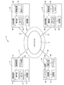
図1は、本開示の第1実施形態の作業装置2の全体構成を示す。作業装置2は、回路基板に対して電子回路部品の組み付け作業(回路基板組立作業)を行なう。作業装置2は、回路基板組立作業を実施する実装装置10(第1装置の一例)、供給装置20(第2装置の一例)及び搬送装置30(第2装置の一例)を備えている。作業装置2は、実装装置10、供給装置20及び搬送装置30の間の双方向の通信を可能とするネットワーク4を備えている。また、作業装置2は、ネットワーク4に接続されたパケットキャプチャ装置40(パケット取得装置の一例)を備えている。なお、ネットワーク4は、複数の装置及びパケットキャプチャ装置40が接続されたイーサネット(登録商標)(ローカルエリアネットワーク)である。
実装装置10は、通信線11によってネットワーク4と接続されており、制御部12、記憶部14、駆動回路16及びヘッド装置18を備えている。実装装置10は、供給装置20及び搬送装置30に対して指令を送信するマスタであり、供給装置20及び搬送装置30は、マスタから指令を受信し、指令に応じて動作を行うスレーブである。実装装置10は、回路部品を回路基板に実装するための装置である。制御部12は、CPU、ROM、RAM、通信インターフェイス等を備え、ROMに記憶されたプログラムがCPUに実行されることにより、各種制御を行うものである。後述の供給装置20の制御部22、搬送装置30の制御部32、パケットキャプチャ装置40の制御部42も、制御部12と同様に構成されている。記憶部14は、実装装置10における動作を記憶するための動作ログ(第1動作ログの一例)等を記憶するためのものである。駆動回路16は、ヘッド装置18を駆動させるための回路であり、制御部12によって制御される。ヘッド装置18は、回路部品を吸着するための吸着部、吸着部を移動させるための移動部、及び回路部品等を撮影するためのカメラ部等を備えている。これらの部分が駆動回路16を介して制御部12によって制御されることで、実装装置10は、回路部品を回路基板に実装する。
なお、制御部12は、リアルタイムクロック13(基準時刻生成部の一例)を備えている。リアルタイムクロック13は、現在時刻(基準時刻の一例)を測定するものであり、詳細は後述する。
なお、制御部12は、リアルタイムクロック13(基準時刻生成部の一例)を備えている。リアルタイムクロック13は、現在時刻(基準時刻の一例)を測定するものであり、詳細は後述する。
供給装置20は、通信線21によってネットワーク4に接続されており、制御部22、記憶部24、駆動回路26及び部品トレイ28を備えている。供給装置20は、回路部品が配列された部品トレイ28を、実装装置10に供給可能な位置に移動させる。記憶部24は、供給装置20における動作を記憶するための供給装置20の動作ログ(第2動作ログの一例)を記憶するものである。駆動回路26は、部品トレイ28を駆動させるための回路である。部品トレイ28は、モータを備え、モータは、駆動回路26を介して制御部22によって制御される。また、制御部22は、クロックカウンタ23(第2装置時刻生成部の一例)を備える。クロックカウンタ23は、実装装置10から取得した現在時刻に基づいて、供給装置20における時刻(第2装置時刻の一例)を測定するものであるが、詳細は後述する。
搬送装置30は、通信線31によってネットワーク4に接続されており、制御部32、記憶部34、駆動回路36及びコンベアベルト38を備えている。搬送装置30は、コンベアベルト38上に置かれた回路基板を特定の作業位置に搬入し、回路基板への作業終了後は、回路基板を搬出するものである。記憶部34は、搬送装置30における動作を記憶するための搬送装置30の動作ログ(第2動作ログの一例)を記憶するものである。駆動回路36は、コンベアベルト38を駆動させるための回路である。コンベアベルト38は、モータを備え、モータは、駆動部36を介して制御部32によって制御される。なお、制御部32は、クロックカウンタ33(第2装置時刻生成部の一例)を備える。クロックカウンタ33は、実装装置10から取得した現在時刻に基づいて、搬送装置30における時刻(第2装置時刻の一例)を測定するものであるが、詳細は後述する。
ここで、実装装置10、供給装置20及び搬送装置30の各装置で計測される時刻について説明する。実装装置10は、リアルタイムクロック13を備えるため、実装装置10における時刻はリアルタイムクロック13によって計測された現在時刻である。また、供給装置20は、カウンタクロック23を備えている。供給装置20の制御部22は、供給装置20を起動したときに、実装装置10に対して、リアルタイムクロック13が計測する現在時刻の取得要求を送信する。この取得要求に対して実装装置10の制御部12は、リアルタイムクロック13が計測する現在時刻を取得し、現在時刻を供給装置20に送信する。現在時刻を受信した供給装置20の制御部22は、受信した現在時刻を基準として、カウンタクロック23によってカウントを行い、供給装置20における時刻(第2装置時刻の一例)を決定する。このように、供給装置20が起動する度に送信されるリアルタイムクロック13の現在時刻に基づいて、供給装置20における時刻を計測するため、供給装置20における時刻を、実装装置10の現在時刻と同じ時刻とすることができる。なお、搬送装置30においても、同様に、取得した現在時刻に基づいて、搬送装置30における時刻が計測される。
図1に示すように、パケットキャプチャ装置40は、通信線41によってネットワーク4に接続されており、制御部42、記憶部44、駆動回路46及びディスプレイ48を備えている。パケットキャプチャ装置40は、ネットワーク4を流れるパケット50を取得するものであり、本実施形態のパケットキャプチャ装置40は、ネットワークを流れるパケットをキャプチャし、解析するためのソフトウェア(以下、パケットキャプチャソフトという)がインストールされたPCである。制御部42は、インストールされたパケットキャプチャソフトを実行する。また、制御部42は、通信線41によって接続されたネットワーク4に流れるパケット50を取得するための通信インターフェイスを備えている。なお、本実施形態においては、「ネットワーク4をパケット50が流れる」と表現し、ネットワークを行き交う「データのひとかたまり(データの単位)」を意味する用語として「パケット」を用いることとする。従って、データリンク層を流れる「データのひとかたまり」としての「フレーム」も「パケット」の一態様であり、本実施形態のように、イーサネットを用いたネットワーク4の場合は、「パケット」を「フレーム」と置き換えても良い。また、ネットワーク4が別の種類のネットワークになった場合は、「パケット」を、データのひとかたまりを示す「セグメント」「データグラム」「メッセージ」と置き換えることができる。
記憶部44は、制御部42によって取得されたパケット50を、記憶するものである。パケットキャプチャソフトが実行されている間は、制御部42が取得したすべてのパケット50が記憶部44に記憶される。駆動回路46は、ディスプレイ48を駆動するための回路である。使用者は、ディスプレイ48に表示された画像に基づいて、パケットキャプチャソフトを実行させ、さらに、記憶部44に記憶された複数のパケット50の中から所望のパケット50に関する情報をディスプレイ48に表示させて、パケット50の解析を行う。
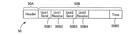
次に、ネットワーク4を流れるパケット50の構造について、図2を参照して説明する。パケット50は、ヘッダー領域50Aとデータ領域50Bを備えている。パケット50のヘッダー領域50Aには、パケット50の送信元のアドレス、送信先のアドレス等が記載されている。また、パケット50のデータ領域50Bは、送信領域50B1、受信領域50B2、送信領域50B3、受信領域50B4、及び時刻書込領域50B5を備えている。送信領域50B1は、供給装置20が実装装置10に送信するデータが書き込まれる領域である。また、受信領域50B2は、供給装置20が実装装置10から受け取るデータ、すなわち、実装装置10が供給装置20に送信するデータが書き込まれる領域である。送信領域50B3は、搬送装置30が実装装置10に送信するデータが書き込まれる領域である。また、受信領域50B4は、搬送装置30が実装装置10から受け取るデータ、すなわち、実装装置10が搬送装置30に送信するデータが書き込まれる領域である。また、時刻書込領域50B5は、実装装置10のリアルタイムクロック13が計測する現在時刻が書き込まれる領域である。本実施形態では、実装装置10がパケット50をネットワーク4に送信するときの現在時刻が、時刻書込領域50B5に書き込まれることになる。ここで、図1を参照して、ネットワーク4を流れるパケット50に関して説明する。
ネットワーク4を流れるすべてのパケット50は、実装装置10の制御部12によって生成される。制御部12は、所定期間毎にパケット50を生成し、通信線11を介してネットワーク4にパケット50を送信する。制御部12は、パケット50を生成し、パケット50をネットワーク4に送信したときの時刻、すなわち、リアルタイムクロック13が測定する現在時刻を、パケット50の時刻書込領域50B5に書き込む。従って、ネットワーク4に流れるすべてのパケット50は、制御部12がパケット50をネットワーク4に送信したときのそれぞれの時刻が、時刻書込領域50B5に付与されたものとなる。このようにして生成されたすべてのパケット50は、実装装置10から通信線11を介してネットワーク4に送信される。
なお、制御部12は、所定時間毎に、それぞれの送信時刻が時刻書込領域50B5に付与された複数のパケット50を、ネットワーク4に送信する。従って、制御部12は、送信又は受信すべきデータを含まないパケット50も所定期間毎に生成する。そのようなパケット50は、ヘッダー領域50Aに、送信元アドレス及び送信先アドレスを有していなし、領域50B1から50B4にデータは書き込まれていない。しかしながら、ネットワーク4を流れるすべてのパケット50は、その時刻書込領域50B5に、当該パケット50のネットワーク4への送信時刻が付与されたものとされている。
実装装置10が供給装置20にデータを送信する場合は、パケット50の受信領域50B2にデータを書き込んだパケット50を作成する。供給装置20は、受信領域50B2にデータが書き込まれたパケット50を受信し、受信領域50B2に書き込まれたデータを取得する。また、同様に、搬送装置30は、受信領域B4にデータが書き込まれたパケット50を受信し、受信領域50B4に書き込まれたデータを取得する。また、供給装置20が実装装置10にデータを送信する場合は、供給装置20は、ネットワーク4を流れているパケット50の送信領域50B1にデータを書き込む。搬送装置30が実装装置10にデータを送信する場合は、搬送装置30は、ネットワーク4を流れているパケット50の送信領域50B3にデータを書き込む。実装装置10は、送信領域50B1に書き込まれたパケット50からデータを取得し、送信元が供給装置20であることを認識する。また、実装装置10は、送信領域50B3に書き込まれたパケット50からデータを取得し、送信元が搬送装置30であることを認識する。図1のネットワーク4に沿う矢印の方向、すなわち、ネットワーク4の時計回り方向に、パケット50がネットワーク4を流れるように構成し、実装装置10、供給装置20、搬送装置30及びパケットキャプチャ装置40を配置することで、実装装置10と、供給装置20及び搬送装置30間のデータの送受信が可能となる。そして、パケットキャプチャ装置40は、供給装置20及び搬送装置30によってデータが書き込まれた後のパケット50を取得することが可能となる。
パケットキャプチャ装置40は、ネットワーク4を流れるすべてのパケット50を受信し、記憶部44に記憶するものである。従って、パケットキャプチャ装置40の記憶部44には、ネットワーク4において、実装装置10と、供給装置20及び搬送装置30との間における、データの送受信のすべてのやり取りが記憶されていることになる。
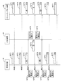
ここで、図3を参照して、ネットワーク4における、実装装置10と供給装置20のパケット50を用いた通信のやり取りについて説明する。なお、図3において、実装装置10から下方に延びる実線の左側の動作ログ10T3から10T6は、実装装置10の記憶部14に記憶される、各時刻が付与された動作ログを示している。また、図3の実装装置10から下方に延びる実線の右側のパケット50T1から50T7は、各時刻において実装装置10から送信されるパケット50を示している。また、供給装置20から下方に延びる実線の左側のパケット50T4及び50T6は、供給装置20が受信したパケット50を示しており、実線の右側の動作ログ20T3から20T6は、供給装置20の記憶部24が記憶する、各時刻が付与された動作ログを示している。また、パケットキャプチャ装置40から下方に延びる実線の右側のパケット50T1~50T7は、パケットキャプチャ装置40の記憶部44が記憶するパケット50を示している。
上述したように、実装装置10は、所定期間毎にパケット50を送信するものであり、時刻T1でパケット50T1をネットワーク4に送信する。パケット50T1の時刻書込領域50B5には、パケット50T1が送信された時刻T1が書き込まれている。このパケット50T1は、送信先及び送信すべきデータがないため、ネットワーク4を流れた後、パケットキャプチャ装置40に取得され、記憶部44に記憶される。また、時刻T1の所定期間後の時刻T2に送信されたパケット50T2も、同様に、記憶部44に記憶される。
上述したように、実装装置10は、所定期間毎にパケット50を送信するものであり、時刻T1でパケット50T1をネットワーク4に送信する。パケット50T1の時刻書込領域50B5には、パケット50T1が送信された時刻T1が書き込まれている。このパケット50T1は、送信先及び送信すべきデータがないため、ネットワーク4を流れた後、パケットキャプチャ装置40に取得され、記憶部44に記憶される。また、時刻T1の所定期間後の時刻T2に送信されたパケット50T2も、同様に、記憶部44に記憶される。
時刻T3において、実装装置10は、パケット50T3をネットワーク4に送信する。パケット50T3は、供給装置20を送信先とするパケットであり、パケット50T3の受信領域50B2には、実装装置10から供給装置20に送信すべきデータが書き込まれている。また、パケット50T3の時刻書込領域50B5には、時刻T3が書き込まれている。実装装置10は、パケット50T3をネットワーク4に送信したときに、動作ログ10T3を生成する。動作ログ10T3には、供給装置20宛てのデータ(供給装置20宛てのデータを含むパケット50T3)をネットワーク4に送信したことを示す情報と、供給装置20宛のデータをネットワーク4に送信したときの、リアルタイムクロック13による現在時刻と、送信したデータの内容を示す情報と、が含まれる。動作ログ10T3は記憶部14に記憶される。
ネットワーク4を流れるパケット50T3は、送信先が供給装置20であるため、時刻T3において、供給装置20は、パケット50T3を受信する。供給装置20は、パケット50T3を受信したときに、動作ログ20T3を生成する。動作ログ20T3には、実装装置10からのデータ(実装装置10からのデータを含むパケット50T3)を受信したことを示す情報と、実装装置10からのデータを受信したときの、クロックカウンタ23による供給装置20における時刻と、受信したデータの内容を示す情報と、が含まれる。クロックカウンタ23による供給装置20における時刻は、実装装置10のリアルタイムクロック13の値を参照して測定されるため、実質的に時刻T3を示すものとなる。動作ログ20T3は記憶部24に記憶される。また、パケット50T3は、パケットキャプチャ装置40に取得され、記憶部44に記憶される。
また、供給装置20は、時刻T4においてネットワーク4を流れているパケット50T4に実装装置10宛てのデータを書き込む。パケット50T4の時時刻書込領域50B5には、時刻T4が書き込まれている。供給装置20がパケット50T4をネットワーク4に送信したときに(データを書き込んだときに)、供給装置20は、動作ログ20T4を生成する。動作ログ20T4には、実装装置10宛てのデータ(実装装置10宛てのデータを含むパケット50T4)を送信した(書き込んだ)ことを示す情報と、実装装置10宛てのデータをネットワーク4に送信したときの、クロックカウンタ23による供給装置20における時刻と、送信したデータの内容を示す情報と、が含まれる。動作ログ20T4は、記憶部24に記憶される。
ネットワーク4を流れるパケット50T4は、送信先が実装装置10であるため、時刻T4において、実装装置10は、パケット50T4を受信する。実装装置10は、パケット50T4を受信したときに、動作ログ10T4を生成する。動作ログ10T4には、供給装置20からのデータ(供給装置20からのデータを含むパケット50T4)を受信したことを示す情報と、実装装置10からのデータを受信したときの、リアルタイムクロック13による現在時刻と、受信したデータの内容を示す情報と、が含まれる。動作ログ10T4は、実装装置10の記憶部14に既往される。また、パケット50T4は、パケットキャプチャ装置40に取得され、記憶部44に記憶される。
その後、同様に、実装装置10によって生成された動作ログ10T5、10T6が記憶部14に記憶され、供給装置20によって生成された動作ログ20T5、20T6が記憶部24に記憶される。また、受信領域50B2にデータが書き込まれ、時刻書込領域50B5に時刻T5が書き込まれたパケット50T5、送信領域50B1にデータが書き込まれ、時刻書込領域50B5に時刻T6が書き込まれたパケット50T6、及び宛先を指定しない、時刻書込領域50B5に時刻T7が書き込まれたパケット50T7が記憶部44に記憶される。
上述のように記憶された動作ログ及びパケットを参照することにより、実装装10と供給装置20の間の通信のやり取りに不具合があったか否かを判断することができる。例えば、時刻T3を含む、実装装置10の動作ログである動作ログ10T3、時刻T3を含む、供給装置20の動作ログである動作ログ20T3、及び、時刻T3を含むパケット50T3を参照する。動作ログ10T3には、時刻T3において、供給装置20宛てのデータを送信したことを示す情報が記載されている。また、動作ログ20T3には、時刻T3において、実装装置10からデータを受信したことを示す情報が記載されている。さらに、パケット50T3には、受信領域50B2に、実装装置10から供給装置20宛てのデータが書き込まれていることが分かる。従って、動作ログ10T3、20T3及びパケット50T3の内容は互いに整合性が取れるため、時刻T3においては、実装装置10と供給装置20との間の通信のやり取りには、不具合が発生していなかったことが分かる。
一方、実装装置10と供給装置20との間の通信のやり取りに、不具合が発生していた場合について述べる。図4においては、動作ログ10T3、10T4、20T3、20T4、及びパケット50T1、50T2、50T3、50T4は、図3と同じである。
時刻T5において、実装装置10は、パケット50T5をネットワーク4に送信する。パケット50T5は、供給装置20を送信先とするパケットであり、パケット50T5の受信領域50B2には、実装装置10から供給装置20に送信すべきデータが書き込まれている。また、パケット50T5の時刻書込領域50B5には、時刻T5が書き込まれている。実装装置10は、パケット50T5をネットワーク4に送信したときに、動作ログ10T5を生成する。動作ログ10T5には、供給装置20宛てのデータ(供給装置20宛てのデータを含むパケット50T5)をネットワーク4に送信したことを示す情報と、供給装置20宛てのデータをネットワーク4に送信したときの現在時刻と、送信したデータの内容を示す情報と、が含まれる。動作ログ10T5は、記憶部14に記憶される。
一方、供給装置20においては、実装装置10との間の通信のやり取りに不具合が生じ、時刻T5にネットワーク4に流れているパケット50T5を受信できていない。この場合、供給装置20は、実装装置10からのデータを受信していないため、時刻T5における動作ログは生成されない。従って、時刻T5を含む動作ログは、記憶部24に記憶されていない。パケットキャプチャ装置40は、時刻T5においてネットワーク4に流れていたパケット50T5を取得し、記憶部44に記憶している。
使用者は、時刻T5以降に、供給装置20において、供給装置20が動作しない不具合を発見し、その不具合が、実装装置10と供給装置20との間の通信のやり取りに起因するものであるか否かを検証する。その際、使用者は、実装装置10の記憶部14に記憶された動作ログの中から時刻T5(第1基準時刻の一例)を含む動作ログ10T5を参照し、実装装置10から供給装置20へのデータの送信動作が行われていたことを検出する(第1基準時刻に対応する時刻を含む第1動作ログに関する情報を取得することの一例)。また、使用者は、供給装置20の記憶部24に記憶された動作ログを参照し、時刻T5を含む動作ログが記憶部24に記憶されていないことを検出する(第1基準時刻に対応する時刻を含む第2動作ログに関する情報を取得することの一例)。さらに、使用者は、パケットキャプチャ装置40の記憶部44に記憶された、時刻T5を含むパケット50T5を参照し、実装装置10から送信されたパケット50T5に、供給装置20宛てのデータが含まれていたことを検出する。実装装置10の動作ログ10T5の内容と、パケット50T5の内容が整合することから、データの送信側としての実装装置10の動作には、問題が無いことが分かる。このように、動作ログ及びパケットを参照することにより、今回発生した不具合が、実装装置10と供給装置20との間の通信のやり取りにおいて発生したことを検出することができる。今回発生した不具合については、実装装置10による送信側の不具合ではなく、供給装置20による受信側の不具合であったことを判別することができる。
また、別の不具合について図5を参照して説明する。図5は、時刻T5において実装装置10によってネットワーク4に送信されるパケット50T51が、図4の時刻T5において実装装置10によって送信されたパケット50T5と異なるが、これ以外の構成は、図4と同じである。
時刻T5において、実装装置10は、パケット50T51をネットワーク4に送信したときに、動作ログ10T5を作成する。動作ログ10T5には、供給装置20宛てのデータをネットワーク4に送信したことを示す情報と、供給装置20宛てのデータをネットワーク4に送信したときの、現在時刻と、送信したデータの内容を示す情報と、が含まれる。動作ログ10T5は、記憶部14に記憶されている。また、実装措置10から時刻T5でネットワーク4に送信されたパケット50T51は、パケットキャプチャ装置40の記憶部44に記憶される。
使用者は、時刻T5以降に、供給装置20において、供給装置20が動作しない不具合を発見し、その不具合が、実装装置10と供給装置20との間の通信のやり取りに起因するものであるか否かを検証する。その際、使用者は、実装装置10の記憶部14に記憶された動作ログの中から時刻T5を含む動作ログ10T5を参照する。また、使用者は、供給装置20の記憶部24に記憶された動作ログを参照し、時刻T5を含む動作ログが記憶部24に記憶されていないことを検出する。さらに、使用者は、パケットキャプチャ装置40の記憶部44に記憶された、時刻T5を含むパケット50T51を参照し、実装装置10から送信されたパケット50T51に、供給装置20宛てのデータが含まれていないことを検出する。動作ログ10T5の内容と、パケット50T51の内容が整合していないことから、今回発生した不具合が、供給装置20の受信側の不具合ではなく、実装装置10の送信側の不具合であったことを判別することができる。
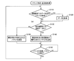
次に、パケット50の各装置間におけるパケットの送受信処理、及び各装置における動作ログの記憶処理に関して、以下に説明する。図6は、実装装置10において実行されるパケット生成・送受信処理を示すフローチャートである。なお、図6のフローチャートは、実装装置10が、供給装置20及び搬送装置30との通信のやり取りを開始したとき以降に実行される。
ステップ110(以下、S110と略称する)において、制御部12は、S110において、制御部12は、実装装置10が実装装置10宛てのデータを含むパケット50を受信したか否かを判断する。実装装置10宛てのデータを含むパケット50を受信した場合(S110:YES)は、S120において、実装装置10宛てのデータを取得する。
一方、実装装置10が実装装置10宛てのデータを含むパケット50を受信していない場合(S110:NO)は、S130において、制御部12は、実装装置10が、他の装置宛てのデータを有しているか否かを判断する。他の装置に送信すべきデータを有していると判断された場合(S130:YES)は、S140において、制御部12は、パケット50の時刻書込領域50B5に現在時刻を書き込み、受信領域50B2又は50B4に他の装置宛てのデータを書き込み、パケット50をネットワーク4に送信する。一方、他の装置に送信すべきデータを有していないと判断された場合(S130:NO)は、制御部12は、パケット50に他の装置宛てのデータを書き込むことなく、現在時刻を時刻書込領域50B5に書き込み、パケット50をネットワーク4に送信する。その後、制御部12は、S140又はS150においてパケット50をネットワーク4に送信してから所定期間が経過したか否かを判断する。所定期間経過していない場合は、制御部12は、繰り返しS160の判断を繰り返す。所定期間経過した場合は、制御部12は、S110の判断に戻る。
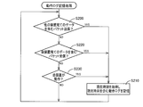
次に、図7を参照し、実装装置10における、動作ログの記憶処理について説明する。なお、図7に示すフローチャートは、実装装置10が起動させられたとき以降に実行されるものである。S200において、制御部12は、実装装置10が他の装置宛てのデータを含むパケット50をネットワーク4に送信したか否かを判断する。実装装置10が他の装置宛てのデータを含むパケット50をネットワーク4に送信したと判断された場合は、S210において、制御部12は、現在時刻を取得して動作ログを作成し、作成された動作ログを記憶部14に記憶させる。動作ログには、他の装置宛てのデータを含むパケット50をネットワーク4に送信したことを示す情報、他の装置宛てのデータをネットワーク4に送信したときの、リアルタイムクロック13による現在時刻、及び送信したデータを示す情報が含まれている。
一方、他の装置宛てのデータを含むパケット50をネットワーク4に送信していないと判断された場合(S200:NO)は、制御部12は、S220において、実装装置10宛てのデータを含むパケット50を受信したか否かを判断する。実装装置10宛てのデータを含むパケット50を受信したと判断された場合は、S210において、制御部12は、現在時刻を取得して動作ログを作成し、作成された動作ログを記憶部14に記憶させる。動作ログには、実装装置10宛てのデータを含むパケット50を受信したことを示す情報と、実装装置10宛てのデータを受信したときの、リアルタイムクロック13による現在時刻、及び、受信したデータを示す情報が含まれている。
一方、実装装置10宛てのデータを含むパケット50を受信していないと判断された場合(S220:NO)には、制御部12は、S230において、実装装置10が動作したか否かを判断する。実装装置10が動作したと判断された場合は、S210において、制御部12は、現在時刻を取得して、動作ログを作成し、作成された動作ログを記憶部14に記憶させる。動作ログには、実装装置10が動作したことを示す情報、実装装置10が動作したときの、リアルタイムクロック13による現在時刻と、が含まれる。一方、実装装置10が動作していないと判断された場合(S230:NO)、制御部12は、処理をS200に戻す。
次に、図8を参照し、供給装置20における、パケット50へのデータの書込み処理、及びパケット50からのデータの取り込み処理を説明する。なお、図8に示すフローチャートは、供給装置20が実装装置10と通信のやり取りを開始したとき以降に実行される。なお、図8及び後述の図9は、供給装置20において実行される処理として説明するが、搬送装置30においても同じ内容の処理が実行されるため、搬送装置30において実行される処理の説明は省略する。
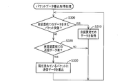
ステップ300において、制御部22は、自装置宛てのデータを含むパケット50を受信したか否かを判断する。自装置宛てのデータを含むパケット50を受信したと判断された場合、制御部22は、S310において、受信したパケット50に含まれる自装置宛てのデータを取得する。一方、自装置宛てのデータを含むパケット50を受信していないと判断された場合(S300:NO)は、S320において、制御部22は、実装装置10宛ての送信データがあるか否かを判断する。実装装置10宛ての送信データがあると判断された場合は、S330において、制御部22は、現在ネットワーク4を流れているパケット50の送信領域50B1に、実装装置10に送信するデータを書き込む。一方、実装装置10宛ての送信データが無いと判断された場合(S330:NO)は、制御部22は、処理をS300に戻す。
次に、図9を参照し、供給装置20における、動作ログの記憶処理について説明する。なお、図9に示すフローチャートは、供給装置20が起動させられたとき以降に実行されるものである。S400において、制御部22は、供給装置20が実装装置10宛てのデータを含むパケット50をネットワーク4に送信したか否かを判断する。制御部22は、供給装置20が実装装置10宛てのデータを送信した場合、すなわち、供給装置20が現在ネットワーク4を流れているパケット50の送信領域50B1に実装装置10宛てのデータを書き込んだ場合は、S400における判断をYESとする。供給装置20が実装装置10宛てのデータを含むパケット50をネットワーク4に送信したと判断された場合は、制御部22は、S410において、供給装置20における時刻を取得して、動作ログを作成し、作成された動作ログを記憶部24に記憶させる。動作ログには、実装装置10宛てのデータを含むパケット50をネットワーク4に送信したことを示す情報、実装装置10宛てのデータをネットワーク4に送信したときの、クロックカウンタ23による供給装置20における時刻、及び実装装置10に送信したデータを示す情報と、が含まれる。
一方、供給装置20が実装装置10宛てのデータを含むパケット50をネットワーク4に送信していないと判断された場合(S400:NO)は、S420において、制御部22は、供給装置20が自装置宛てのデータを含むパケット50を受信したか否かを判断する。供給装置20が自装置宛てのデータを含むパケット50を受信したと判断された場合は、S410において、制御部22は、動作ログを作成し、作成された動作ログを記憶部24に記憶させる。動作ログには、供給装置20が自装置宛てのデータを含むパケット50を受信したことを示す情報、供給装置20が自装置宛てのデータを受信したときの、カウンタクロック23による供給装置20における時刻、及び供給装置20が受信したデータを示す情報と、が含まれる。
一方、供給装置20が自装置宛てのデータを含むパケット50を受信していないと判断された場合(S420:NO)は、S430において、制御部22は、自装置が動作したか否かを判断する。自装置が動作したと判断された場合は、S410において、制御部22は、供給装置2における時刻を取得して、動作ログを作成し、作成された動作ログを記憶部24に記憶させる。動作ログには、自動値が動作したこと(動作内容)を示す情報、自装置が動作したときの、カウンタクロック23による供給装置20における時刻と、が含まれる。
一方、供給装置20が動作していないと判断された場合(S430:NO)は、制御部22は、S400に処理を戻す。
以上説明したように、本実施形態の作業装置2においては、動作時刻を含む実装装置10の動作ログが記憶部14に記憶され、動作時刻を含む供給装置20の動作ログが記憶部24記憶され、動作時刻を含む搬送装置30の動作ログが記憶部34に記憶され、さらに、動作時刻を含むすべてのパケット50が記憶部44に記憶されている。従って、同じ動作時刻における、実装装置10の動作ログ、供給装置20の動作ログ、搬送装置30の動作ログ、及び同じ動作時刻を含むパケット50を参照することにより、動作の不具合が、実装装置10、供給装置20、搬送装置30のいずれの装置の通信不具合に起因するものであるとかを判別することができる。
また、実装装置10は、自装置宛てのデータを受信したとき、及び他の装置宛てのデータを送信したときに、受信動作時刻又は送信動作時刻を含む動作ログを作成し、記憶させる。従って、記憶された動作ログと、パケットキャプチャ装置40に記憶された、時刻情報を含むパケット50との整合性を確認することができる。
また、供給装置20及び搬送装置30は、自装置宛てのデータを含むパケット50を受信したとき、及び実装装置10宛てのデータを含むパケット50を送信したときに、受信動作時刻又は送信動作時刻を含む動作ログを作成し、記憶させる。従って、記憶された動作ログと、パケットキャプチャ装置40に記憶された、時刻情報を含むパケット50との整合性を確認することができる。
また、供給装置20及び搬送装置30は、実装装置10からの現在時刻に基づいて、供給装置20における時刻、及び搬送装置30における時刻を計測するため、実装装置10とほぼ同一の時刻を得ることができる。
また、供給装置20及び搬送装置30は、実装装置10からの現在時刻に基づいて、供給装置20における時刻、及び搬送装置30における時刻を計測するため、実装装置10とほぼ同一の時刻を得ることができる。
また、ネットワーク4を流れるすべてのパケット50に、実装装置10が現在時刻を付与するため、パケットキャプチャ装置40の記憶部44に記憶されたパケット50と、各装置の動作ログとの整合性を確認することができる。
なお、本実施形態においては、供給装置20及び搬送装置30は、実装装置10から送信された、リアルタイムクロック13による現在時刻に基づいて、カウンタクロック23,33を用いて供給装置20における時刻、又は搬送装置30における時刻を計測したが、本開示はこれに限られるものでは無い。例えば、供給装置20は、自装置宛てのデータを含むパケット50(第1パケットの一例)を受信したときに、自装置宛てのデータを含むパケット50に含まれる現在時刻をパケット50から抽出し、抽出した現在時刻を、その時に作成する動作ログに付与しても良い。このように構成した場合は、供給装置20は、実装装置10の動作ログと同じ時刻が付与された動作ログを作成することが可能となる。また、供給装置20が起動する度に実装装置10に現在時刻の送信要求を行う必要が無くなるため、供給装置20における制御が簡略化される。また、供給装置20のカウンタクロック23を備えることが不要となる。
2:作業装置
4:ネットワーク
10:実装装置
12:制御部
13:リアルタイムクロック
14:記憶部
16:駆動回路
18:ヘッド装置
20:供給装置
22:制御部
24:記憶部
26:駆動回路
28:部品トレイ
30:搬送装置
32:制御部
34:記憶部
36:駆動回路
38:コンベアベルト
40:パケットキャプチャ装置
42:制御部
44:記憶部
46:駆動回路
48:ディスプレイ
50、50T1~50T7:パケット
50A:ヘッダー領域
50B:データ領域
50B1:送信領域
50B2:受信領域
50B3:送信領域
50B4:受信領域
50B5:時刻書込領域
10T3~10T6:動作ログ
20T3~20T6:動作ログ
50T1~50T7:パケット
4:ネットワーク
10:実装装置
12:制御部
13:リアルタイムクロック
14:記憶部
16:駆動回路
18:ヘッド装置
20:供給装置
22:制御部
24:記憶部
26:駆動回路
28:部品トレイ
30:搬送装置
32:制御部
34:記憶部
36:駆動回路
38:コンベアベルト
40:パケットキャプチャ装置
42:制御部
44:記憶部
46:駆動回路
48:ディスプレイ
50、50T1~50T7:パケット
50A:ヘッダー領域
50B:データ領域
50B1:送信領域
50B2:受信領域
50B3:送信領域
50B4:受信領域
50B5:時刻書込領域
10T3~10T6:動作ログ
20T3~20T6:動作ログ
50T1~50T7:パケット
Claims (9)
- ネットワークに接続された第1装置であって、前記第1装置の動作のログである第1動作ログを記憶する第1記憶部と、基準時刻を生成する基準時刻生成部と、を備える第1装置と、
前記ネットワークを介して前記第1装置と通信可能である第2装置であって、前記第2装置の動作ログである第2動作ログを記憶する第2記憶部を備える第2装置と、を備える作業装置であって、
前記第1装置は、前記ネットワークを流れる複数のパケットのうちの少なくとも1つを用いて、情報を受信すること及び情報を送信することが可能であり、且つ、前記複数のパケットのすべてに対して前記基準時刻生成部によって生成された前記基準時刻を付与するものであり、
前記第2装置は、前記複数のパケットの少なくとも1つを用いて、情報を受信すること、及び情報を送信することが可能であり、
前記第1装置は、前記基準時刻に対応する時刻を含む第1動作ログを前記第1記憶部に記憶させるものであり、
前記第2装置は、前記基準時刻に対応する時刻を含む第2動作ログを前記第2記憶部に記憶させるものであり、
前記作業装置は、
前記ネットワークに接続され、前記ネットワークに流れる、前記第1装置によって前記基準時刻が付与された前記複数のパケットのすべてを取得して記憶する第3記憶部を備えるパケット取得装置を、さらに備える作業装置。
- 前記第1装置は、前記複数のパケットのうちの少なくとも1つを用いて前記情報を受信したときに、前記情報を受信したことを示す情報、及び前記情報を受信した時点の前記基準時刻を含む前記第1動作ログを、前記第1記憶部に記憶させる請求項1に記載の作業装置。
- 前記第1装置は、前記複数のパケットのうちの少なくとも1つを用いて前記情報を送信したときに、前記情報を送信したことを示す情報、及び前記情報を送信した時点の前記基準時刻を含む前記第1動作ログを、前記第1記憶部に記憶させる請求項1又は2に記載の作業装置。
- 前記第2装置は、前記複数のパケットのうちの少なくとも1つを用いて前記情報を受信したときに、前記情報を受信したことを示す情報、及び前記情報を受信した時点の前記基準時刻に対応する時刻を含む前記第2動作ログを、前記第2記憶部に記憶させる請求項1から3にいずれかに記載の作業装置。
- 前記第2装置は、前記複数のパケットのうちの少なくとも1つを用いて前記情報を送信したときに、前記情報を送信したことを示す情報、及び前記情報を送信した時点の前記基準時刻に対応する時刻を含む前記第2動作ログを、前記第2記憶部に記憶させる請求項1から4のいずれかに記載の作業装置。
- 前記第2装置は、前記第1装置から取得した前記基準時刻に基づいて、前記第2装置における時刻である第2装置時刻を生成する第2装置時刻生成部を、さらに備え、
前記第2装置は、前記第2装置時刻生成部によって生成された前記第2装置時刻を含む前記第2動作ログを、前記第2記憶部に記憶させる請求項1から5のいずれかに記載の作業装置。
- 前記第2装置は、前記複数のパケットのうちの少なくとも1つである、第1パケットから前記情報を受信したときに、前記第1パケットから抽出した前記基準時刻を含む前記第2動作ログを、前記第2記憶部に記憶させる請求項1から5のいずれかに記載の作業装置。
- 前記第1装置は、前記複数のパケットのすべてを生成し、生成したすべてのパケットに前記基準時刻を書き込むものである請求項1から7のいずれかに記載の作業装置。
- ネットワークに接続された第1装置であって、前記第1装置の動作のログである第1動作ログを記憶する第1記憶部と、基準時刻を生成する基準時刻生成部と、を備える第1装置と、前記ネットワークを介して前記第1装置と通信可能である第2装置であって、前記第2装置の動作ログである第2動作ログを記憶する第2記憶部を備える第2装置と、を備える作業装置であって、前記第1装置は、前記ネットワークを流れる複数のパケットのうちの少なくとも1つを用いて、情報を受信すること及び情報を送信することが可能であり、且つ、前記複数のパケットのすべてに対して前記基準時刻生成部によって生成された前記基準時刻を付与するものであり、前記第2装置は、前記複数のパケットの少なくとも1つを用いて、情報を受信すること、及び情報を送信することが可能であり、前記第1装置は、前記基準時刻に対応する時刻を含む第1動作ログを前記第1記憶部に記憶させるものであり、前記第2装置は、前記基準時刻に対応する時刻を含む第2動作ログを前記第2記憶部に記憶させるものであり、前記作業装置は、前記ネットワークに接続され、前記ネットワークに流れる、前記第1装置によって前記基準時刻が付与された前記複数のパケットのすべてを取得して記憶する第3記憶部を備えるパケット取得装置を、さらに備える作業装置の動作確認方法であって、
前記基準時刻が第1基準時刻のときの前記第1装置及び前記第2装置の動作を確認する場合、
前記第1基準時刻を含む第1動作ログに関する情報を前記第1記憶部から取得するステップと、
前記第1基準時刻に対応する時刻を含む第2動作ログに関する情報を前記第2記憶部から取得するステップと、
前記第1基準時刻を含むパケットを前記第3記憶部から取得するステップと、
取得した前記第1動作ログに関する情報、取得した前記第2動作ログに関する情報、及び取得した前記パケットと、を比較して、前記第1基準時刻における前記第1装置及び前記第2装置の動作を確認するステップと、を備える作業装置の動作確認方法。
Priority Applications (2)
| Application Number | Priority Date | Filing Date | Title |
|---|---|---|---|
| JP2020500238A JP7075475B2 (ja) | 2018-02-19 | 2018-02-19 | 作業装置および作業装置の動作確認方法 |
| PCT/JP2018/005752 WO2019159362A1 (ja) | 2018-02-19 | 2018-02-19 | 作業装置および作業装置の動作確認方法 |
Applications Claiming Priority (1)
| Application Number | Priority Date | Filing Date | Title |
|---|---|---|---|
| PCT/JP2018/005752 WO2019159362A1 (ja) | 2018-02-19 | 2018-02-19 | 作業装置および作業装置の動作確認方法 |
Publications (1)
| Publication Number | Publication Date |
|---|---|
| WO2019159362A1 true WO2019159362A1 (ja) | 2019-08-22 |
Family
ID=67618594
Family Applications (1)
| Application Number | Title | Priority Date | Filing Date |
|---|---|---|---|
| PCT/JP2018/005752 Ceased WO2019159362A1 (ja) | 2018-02-19 | 2018-02-19 | 作業装置および作業装置の動作確認方法 |
Country Status (2)
| Country | Link |
|---|---|
| JP (1) | JP7075475B2 (ja) |
| WO (1) | WO2019159362A1 (ja) |
Citations (4)
| Publication number | Priority date | Publication date | Assignee | Title |
|---|---|---|---|---|
| JP2007101306A (ja) * | 2005-10-03 | 2007-04-19 | Mitsubishi Electric Engineering Co Ltd | Plc用時刻同期装置 |
| JP2012175389A (ja) * | 2011-02-21 | 2012-09-10 | Nippon Telegr & Teleph Corp <Ntt> | ログ収集自動化装置、ログ収集自動化試験システム、及びログ収集制御方法 |
| JP2013121014A (ja) * | 2011-12-06 | 2013-06-17 | Nippon Telegr & Teleph Corp <Ntt> | 時刻同期装置及び方法 |
| WO2014200070A1 (ja) * | 2013-06-13 | 2014-12-18 | オムロン株式会社 | 情報処理装置、情報処理装置の制御方法および制御プログラム |
-
2018
- 2018-02-19 JP JP2020500238A patent/JP7075475B2/ja active Active
- 2018-02-19 WO PCT/JP2018/005752 patent/WO2019159362A1/ja not_active Ceased
Patent Citations (4)
| Publication number | Priority date | Publication date | Assignee | Title |
|---|---|---|---|---|
| JP2007101306A (ja) * | 2005-10-03 | 2007-04-19 | Mitsubishi Electric Engineering Co Ltd | Plc用時刻同期装置 |
| JP2012175389A (ja) * | 2011-02-21 | 2012-09-10 | Nippon Telegr & Teleph Corp <Ntt> | ログ収集自動化装置、ログ収集自動化試験システム、及びログ収集制御方法 |
| JP2013121014A (ja) * | 2011-12-06 | 2013-06-17 | Nippon Telegr & Teleph Corp <Ntt> | 時刻同期装置及び方法 |
| WO2014200070A1 (ja) * | 2013-06-13 | 2014-12-18 | オムロン株式会社 | 情報処理装置、情報処理装置の制御方法および制御プログラム |
Also Published As
| Publication number | Publication date |
|---|---|
| JP7075475B2 (ja) | 2022-05-25 |
| JPWO2019159362A1 (ja) | 2021-02-25 |
Similar Documents
| Publication | Publication Date | Title |
|---|---|---|
| JP6509477B2 (ja) | 制御装置および制御プログラム | |
| JP5930355B1 (ja) | 特定パケット中継機能付きデータダイオード装置及びその設定方法 | |
| CN107526681B (zh) | 一种机器人的测试系统及测试方法 | |
| CN117130318B (zh) | 工业数据采集方法、装置、系统和可读存储介质 | |
| TW201635167A (zh) | 使用者端主機備援系統及其實施方法 | |
| CN115913884B (zh) | 通信方法、EtherCAT系统、通信装置及存储介质 | |
| CN104950880B (zh) | 工控设备调试系统及方法 | |
| JP7075475B2 (ja) | 作業装置および作業装置の動作確認方法 | |
| CN110545211A (zh) | 工业控制系统中的无中断消息捕获 | |
| KR100778114B1 (ko) | 통신에러를 개선하기 위한 통신방법 및 그 통신방법이적용된 전자장치 | |
| EP3690577B1 (en) | Management system and management method for cutting machine | |
| JP4992573B2 (ja) | レイヤ2スイッチ、通信機器及びそれらに用いるデータ部エラー検出方法並びにそのプログラム | |
| CN105763347B (zh) | 用于获取参数的方法、网络设备及系统 | |
| JP3658325B2 (ja) | ネットワーク・インターフェース装置、デバイス端末装置、及びネットワーク・インターフェース装置の制御方法 | |
| JP5001912B2 (ja) | ノード及びネットワークシステム | |
| JP2010021866A (ja) | 通信システム及びマスタ | |
| US10459816B2 (en) | Communication setting notification apparatus | |
| CN118923096A (zh) | 信息交互方法及装置、计算设备、存储介质 | |
| JP2014197346A (ja) | コントローラおよびプログラム | |
| JP4500085B2 (ja) | テスト支援装置及びテスト支援方法 | |
| JPWO2022004831A5 (ja) | サーバ装置、監視方法、及びプログラム | |
| JP2005085078A (ja) | 省電力対応装置を含むネットワークシステム | |
| KR20120089931A (ko) | 통신 인터락 장치를 포함하는 자동화 설비 | |
| JP4207032B2 (ja) | ファームウェア送信プログラム、制御方法、データ送信装置、及びネットワークシステム | |
| CN118093284B (zh) | 一种机载智能显示器的测试方法及设备 |
Legal Events
| Date | Code | Title | Description |
|---|---|---|---|
| 121 | Ep: the epo has been informed by wipo that ep was designated in this application |
Ref document number: 18906007 Country of ref document: EP Kind code of ref document: A1 |
|
| ENP | Entry into the national phase |
Ref document number: 2020500238 Country of ref document: JP Kind code of ref document: A |
|
| NENP | Non-entry into the national phase |
Ref country code: DE |
|
| 122 | Ep: pct application non-entry in european phase |
Ref document number: 18906007 Country of ref document: EP Kind code of ref document: A1 |